KR102592197B1 - Vision recognition-based shipbuilding equipment steel fittings shape assembly and welding automation system - Google Patents
Vision recognition-based shipbuilding equipment steel fittings shape assembly and welding automation systemDownload PDFInfo
- Publication number
- KR102592197B1 KR102592197B1KR1020230064459AKR20230064459AKR102592197B1KR 102592197 B1KR102592197 B1KR 102592197B1KR 1020230064459 AKR1020230064459 AKR 1020230064459AKR 20230064459 AKR20230064459 AKR 20230064459AKR 102592197 B1KR102592197 B1KR 102592197B1
- Authority
- KR
- South Korea
- Prior art keywords
- welding
- shape
- welded
- data
- robot
- Prior art date
- Legal status (The legal status is an assumption and is not a legal conclusion. Google has not performed a legal analysis and makes no representation as to the accuracy of the status listed.)
- Active
Links
Images


Classifications
- B—PERFORMING OPERATIONS; TRANSPORTING
- B23—MACHINE TOOLS; METAL-WORKING NOT OTHERWISE PROVIDED FOR
- B23K—SOLDERING OR UNSOLDERING; WELDING; CLADDING OR PLATING BY SOLDERING OR WELDING; CUTTING BY APPLYING HEAT LOCALLY, e.g. FLAME CUTTING; WORKING BY LASER BEAM
- B23K37/00—Auxiliary devices or processes, not specially adapted for a procedure covered by only one of the other main groups of this subclass
- B—PERFORMING OPERATIONS; TRANSPORTING
- B23—MACHINE TOOLS; METAL-WORKING NOT OTHERWISE PROVIDED FOR
- B23K—SOLDERING OR UNSOLDERING; WELDING; CLADDING OR PLATING BY SOLDERING OR WELDING; CUTTING BY APPLYING HEAT LOCALLY, e.g. FLAME CUTTING; WORKING BY LASER BEAM
- B23K9/00—Arc welding or cutting
- B23K9/10—Other electric circuits therefor; Protective circuits; Remote controls
- B23K9/1006—Power supply
- B—PERFORMING OPERATIONS; TRANSPORTING
- B23—MACHINE TOOLS; METAL-WORKING NOT OTHERWISE PROVIDED FOR
- B23K—SOLDERING OR UNSOLDERING; WELDING; CLADDING OR PLATING BY SOLDERING OR WELDING; CUTTING BY APPLYING HEAT LOCALLY, e.g. FLAME CUTTING; WORKING BY LASER BEAM
- B23K9/00—Arc welding or cutting
- B23K9/12—Automatic feeding or moving of electrodes or work for spot or seam welding or cutting
- B23K9/127—Means for tracking lines during arc welding or cutting
- B23K9/1272—Geometry oriented, e.g. beam optical trading
- B23K9/1274—Using non-contact, optical means, e.g. laser means
- B—PERFORMING OPERATIONS; TRANSPORTING
- B23—MACHINE TOOLS; METAL-WORKING NOT OTHERWISE PROVIDED FOR
- B23Q—DETAILS, COMPONENTS, OR ACCESSORIES FOR MACHINE TOOLS, e.g. ARRANGEMENTS FOR COPYING OR CONTROLLING; MACHINE TOOLS IN GENERAL CHARACTERISED BY THE CONSTRUCTION OF PARTICULAR DETAILS OR COMPONENTS; COMBINATIONS OR ASSOCIATIONS OF METAL-WORKING MACHINES, NOT DIRECTED TO A PARTICULAR RESULT
- B23Q17/00—Arrangements for observing, indicating or measuring on machine tools
- B23Q17/24—Arrangements for observing, indicating or measuring on machine tools using optics or electromagnetic waves
- B23Q17/2452—Arrangements for observing, indicating or measuring on machine tools using optics or electromagnetic waves for measuring features or for detecting a condition of machine parts, tools or workpieces
- B23Q17/2471—Arrangements for observing, indicating or measuring on machine tools using optics or electromagnetic waves for measuring features or for detecting a condition of machine parts, tools or workpieces of workpieces
- G—PHYSICS
- G05—CONTROLLING; REGULATING
- G05B—CONTROL OR REGULATING SYSTEMS IN GENERAL; FUNCTIONAL ELEMENTS OF SUCH SYSTEMS; MONITORING OR TESTING ARRANGEMENTS FOR SUCH SYSTEMS OR ELEMENTS
- G05B19/00—Programme-control systems
- G05B19/02—Programme-control systems electric
- G05B19/18—Numerical control [NC], i.e. automatically operating machines, in particular machine tools, e.g. in a manufacturing environment, so as to execute positioning, movement or co-ordinated operations by means of programme data in numerical form
- G05B19/19—Numerical control [NC], i.e. automatically operating machines, in particular machine tools, e.g. in a manufacturing environment, so as to execute positioning, movement or co-ordinated operations by means of programme data in numerical form characterised by positioning or contouring control systems, e.g. to control position from one programmed point to another or to control movement along a programmed continuous path
- G—PHYSICS
- G05—CONTROLLING; REGULATING
- G05B—CONTROL OR REGULATING SYSTEMS IN GENERAL; FUNCTIONAL ELEMENTS OF SUCH SYSTEMS; MONITORING OR TESTING ARRANGEMENTS FOR SUCH SYSTEMS OR ELEMENTS
- G05B2219/00—Program-control systems
- G05B2219/30—Nc systems
- G05B2219/45—Nc applications
- G05B2219/45104—Lasrobot, welding robot
Landscapes
- Engineering & Computer Science (AREA)
- Physics & Mathematics (AREA)
- Mechanical Engineering (AREA)
- Optics & Photonics (AREA)
- Plasma & Fusion (AREA)
- Geometry (AREA)
- Human Computer Interaction (AREA)
- Manufacturing & Machinery (AREA)
- General Physics & Mathematics (AREA)
- Automation & Control Theory (AREA)
- Butt Welding And Welding Of Specific Article (AREA)
Abstract
Description
Translated fromKorean본 발명은, 선박의 건조시에 선박을 구성하는 조선기자재(철의장품)의 용접제조시 로봇용접장치를 통해 자동화 작업시스템을 구현하도록 된 용접 자동화 시스템에 관한 것이다.The present invention relates to a welding automation system that implements an automated work system through a robot welding device during the welding and manufacturing of shipbuilding equipment (iron equipment) constituting the ship during ship construction.
구체적으로는, 각각의 조선기자재(철의장품)들을 형상조립(가용접; tack welding) 및 용접조립(본용접)할 때, 자동화공정을 통해 제조하도록 됨으로써, 생산효율을 향상시키고 불량을 제거하여 제조품질을 증대할 수 있도록 된 비전인식기반 조선기자재 철의장품 형상조립 및 용접 자동화 시스템에 관한 것이다.Specifically, each shipbuilding equipment (iron equipment) is manufactured through an automated process when assembling the shape (tack welding) and welding (main welding), thereby improving production efficiency and eliminating defects. It is about a vision recognition-based shipbuilding equipment and iron fittings shape assembly and welding automation system that can improve quality.
일반적으로, 대형 선박을 건조하는 경우에 선박의 구성 요소에 해당하는 다수의 조선기자재(철의장품)들을 각각의 제조현장들에서 맞춤되게 제조한 후, 별도의 전체 조립현장에서 각각의 구성품들을 조립하여 선박을 건조하게 된다.Generally, when building a large ship, a number of shipbuilding materials (iron equipment) corresponding to the ship's components are custom-manufactured at each manufacturing site, and then each component is assembled at a separate assembly site. A ship will be built.
즉, 각각의 조선기자재(철의장품)들을 구성하는 각각의 자재(부품)들이 서로 다른 부품제조현장에서 각각 제조된 후, 각각의 조선기자재(철의장품)의 조립현장들에서 각각의 자재(부품)들을 형상조립 및 용접하여 설계된 조선기자재(철의장품)가 조립되고, 각각 조립된 다수의 조선기자재(철의장품)들이 선박의 전체 조립현장에서 용접조립되는 과정을 각각 진행하여 선박이 건조된다.In other words, after each material (part) that makes up each shipbuilding equipment (steel equipment) is manufactured at different parts manufacturing sites, each material (part) is manufactured at the assembly sites of each shipbuilding equipment (iron equipment). The designed shipbuilding equipment (iron equipment) is assembled by shape-assembling and welding, and a number of each assembled shipbuilding equipment (iron equipment) is welded and assembled at the entire ship assembly site to build the ship.
상기에서, 선박을 구성하는 각각의 조선기자재(철의장품)들의 주요 자재(부품)들은, '형강재(H형강,I형강,등형ㄱ형강,찬넬)'로 이루어지며, 단면의 형상이 다각적인 형상을 갖는 조강류의 제품을 사용하여 제품을 생산하게 된다.In the above, the main materials (parts) of each shipbuilding equipment (iron equipment) constituting the ship are made of 'beam steel (H-beam steel, I-beam steel, equal-shaped A-beam steel, channel)' and have a multi-faceted cross-sectional shape. Products are produced using shaped crude steel products.
한편, 선박 건조 시 사용되는 조선기자재(철의장품)들은, 통상적으로, 척당 7,000~9,000여개가 사용되고 있으며, 선박의 선종 및 선형에 따라 제품형상, 크기, 중량이 매우 다양하게 이루어진다.Meanwhile, shipbuilding equipment (iron equipment) used in ship construction is typically used in the number of 7,000 to 9,000 pieces per ship, and the product shape, size, and weight vary greatly depending on the type and type of ship.
이에 따라, 로봇 용접 자동화 시스템을 통해 전체 물량을 자동으로 형상조립 공정 및 용접 공정을 수행할 경우에는, 생산제품 특성상 전체 제품에 대해 단계적으로 접근할 필요가 있다.Accordingly, when the shape assembly process and welding process are automatically performed on the entire quantity through a robot welding automation system, it is necessary to approach the entire product in stages due to the nature of the product.
즉, 로봇 용접 자동화 대상으로 되는 피용접물 대상 공정을 선정하기 위해서는, 공정 물량이 많아야 하고(자동화 효과 증대), 공정 난이도가 낮아 작업자 투입이 비효율적이어야 하며, 공정 난이도가 높아 고급 작업자가 필수적이여야 하며, 공장 여건상 로봇 용접 시스템이 설치 운용이 가능하여야 하고, 자동화 시스템 구축 이후 작업자의 관리가 최소화 되어야 하며, 상용 판매 제품으로 단위 부품을 선정하여 시스템을 구성하여야 한다.In other words, in order to select a process for welding objects subject to robot welding automation, the process volume must be large (increasing the automation effect), the process difficulty must be low, so operator input must be inefficient, and the process difficulty must be high, so advanced workers must be essential. , the robot welding system must be capable of installation and operation due to factory conditions, operator management must be minimized after the automation system is established, and the system must be configured by selecting unit parts from commercially available products.
이때, 개발 제품으로 시스템을 구성할 경우 유지보수가 어려우며, 시스템 안정성을 보장하기 어려움이 발생하게 된다.At this time, if the system is configured with a developed product, maintenance is difficult and it is difficult to guarantee system stability.
그리고 선박 등과 같은 대형 구조물을 구성하는 철의장품의 경우에는, 피용접물의 공정을 수행하는데 장비 사양이 증대되며, 로봇의 구동 방식이 겐트리 형태로 이동하면서 작업을 수행해야 하므로 작업이 비효율적이고 투자비용이 과다하게 책정되는 문제점이 있으며, 공정 난이도는 비교적 높으나 피용접물 수량이 많아 생산 과정상에 고숙련자 인력 수급이 어려워 고급 용접 작업자가 생산에 투입이 되는 소형 자재를 작업 대상물로 우선 선정하여 로봇 용접 자동화 시스템을 우선 선정하고 점진적 확장이 필요하게 된다.And in the case of iron fittings that make up large structures such as ships, the equipment specifications are increased to perform the process of the welded object, and the robot's driving method must perform the work while moving in a gantry type, which makes the work inefficient and increases investment costs. There is a problem with over-pricing, and although the difficulty of the process is relatively high, the number of objects to be welded is large, so it is difficult to supply highly skilled manpower during the production process, so advanced welders first select small materials to be used in production as work objects and automate robot welding. A system must be selected first and then gradually expanded.
이러한 문제점에 대하여 제안된 종래의 로봇용접 자동화설비의 하나로, 한국특허출원번호 제10-2020-0085135호(명칭: 로봇을 이용한 파이프서포트의 용접 자동화 시스템)이 있으며, 공보에 공지된 바와 같이, 레일, 로봇암 및 제어기를 주요하게 포함하는 로봇을 이용한 파이프서포트의 용접 자동화 시스템에 있어서, 상기 로봇암은 상기 레일의 일측에서 레일 상면에 용접을 수행하도록 구성되되, 용접을 수행하는 용접건과, 상기 레일 상의 파이프서포트의 구성품의 형태를 식별하기 위한 센서를 포함하되, 상기 로봇암은 상기 레일의 일측에서 레일 상면에 용접을 수행하도록 구성되되, 용접을 수행하는 용접건과, 상기 레일 상의 파이프서포트의 구성품의 형태를 식별하기 위한 센서를 포함하되, 상기 로봇암은, 전, 후, 좌, 우, 상 및 하 모두의 방향으로 구동 가능한 다관절 로봇암이고, 상기 제어기는, 상기 로봇암에 구성된 용접건으로 용접소스를 공급하고, 로봇암의 센서로부터 식별된 구성품의 형태에 기반한 용접을 수행하도록 제어하는 기능을 수행하며, 선박의 3D설계정보 혹은 조선소의 3D설계정보를 기반으로 파이프서포트의 형태정보를 추출하여 저장하는, 형태정보추출부와; 상기 형태정보추출부를 통해 추출된 형태정보에 기반하여, 용접정보를 추출하여 저장하는, 용접정보추출부와; 상기 로봇암에 구성된 센서의 센서값을 수신하고, 수신된 센서값에 기반하여 파이프서포트의 구성품의 형태를 파악하는, 센서값수신부와; 상기 센서값수신부에 의해 파악된 구성품의 형태를, 상기 형태정보추출부를 통해 추출된 형태와 비교하고, 해당 형태에 따른 용접정보를 로딩하는, 비교 및 용접정보 로딩부와; 상기 비교 및 용접정보 로딩부에 의해 로딩된 용접정보에 기반하여 로봇암이 용접을 수행할 수 있도록 제어하는, 용접제어부;를 포함하여 구성되고, 상기 레일은, 상면에서부터 하방으로 오목한 홈부를 포함하며, 상기 홈부는 레일의 폭방향으로 2개가 마주하는 방향으로 형성되어, 2개의 홈부가 레일의 길이방향으로 일정간격마다 다수 개 형성되도록 하되, 각 홈부에는 바(bar)가 홈부의 폭방향을 따라 이동될 수 있도록 구성되고, 상기 바의 안정적인 가이드를 위하여 바의 홈부의 내측벽에 닿는 일측으로 돌기를 형성하고, 상기 홈부의 내측벽에는 오목하되 폭방향으로 연장된 가이드홈이 형성되어 상기 돌기가 가이드홈에 내삽된 상태로 고정되도록 하며, 상기 돌기와 가이드홈은 그 형상이 '凸'의 다단 형상을 가지도록 구성하고, 상기 레일의 단부방향에 해당하는 홈부의 내측면에서부터 바의 일면까지는 다수 개의 스프링이 연결되어 바에 탄성을 제공하고, 상기 바의 다른 방향의 일면으로는 전자석이 바의 내측에 내장되도록 구성함으로써, 2개의 대칭방향으로 마주하는 홈부 내에 위치된 각각의 바는, 바(bar) 사이에 상술된 구성품이 위치된 상태로, 전자석이 온(On) 제어되는 경우, 2개의 바가 구성품을 향해 움직이면서 폭을 좁혀 구성품을 잡아주게 되어 정렬이 가능하도록 하고, 전자석이 오프(Off) 제어되는 경우, 바는 스프링의 탄성에 의해 다시 구성품으로부터 멀어지도록 하는 로봇을 이용한 파이프서포트의 용접 자동화 시스템이 기재되어 있다.One of the conventional robot welding automation equipment proposed to address this problem is Korean Patent Application No. 10-2020-0085135 (name: pipe support welding automation system using a robot), and as known in the gazette, rail In the pipe support welding automation system using a robot, which mainly includes a robot arm and a controller, the robot arm is configured to perform welding on the upper surface of the rail from one side of the rail, and includes a welding gun for performing welding, and It includes a sensor for identifying the shape of the component of the pipe support on the rail, wherein the robot arm is configured to perform welding on the upper surface of the rail from one side of the rail, a welding gun for performing welding, and It includes a sensor for identifying the shape of the component, wherein the robot arm is a multi-joint robot arm that can be driven in all directions of forward, backward, left, right, up and down, and the controller is a welding device configured on the robot arm. It supplies welding source to the gun, performs a control function to perform welding based on the shape of the component identified from the robot arm sensor, and provides shape information of the pipe support based on the 3D design information of the ship or the 3D design information of the shipyard. a form information extraction unit that extracts and stores the information; a welding information extraction unit that extracts and stores welding information based on the shape information extracted through the shape information extraction unit; a sensor value receiving unit that receives sensor values from sensors configured in the robot arm and determines the shape of the components of the pipe support based on the received sensor values; a comparison and welding information loading unit that compares the shape of the component identified by the sensor value receiver with the shape extracted through the shape information extraction unit and loads welding information according to the shape; A welding control unit that controls the robot arm to perform welding based on the welding information loaded by the comparison and welding information loading unit, wherein the rail includes a groove concave downward from the upper surface; , The groove portions are formed in two facing directions in the width direction of the rail, so that a plurality of two groove portions are formed at regular intervals in the longitudinal direction of the rail, and a bar is formed in each groove portion along the width direction of the groove portion. It is configured to be movable, and for stable guidance of the bar, a protrusion is formed on one side that touches the inner wall of the groove portion of the bar, and a guide groove that is concave but extends in the width direction is formed on the inner wall of the groove portion so that the protrusion It is fixed in an interpolated state in the guide groove, and the protrusion and guide groove are configured to have a 'convex' multi-stage shape, and a plurality of grooves are formed from the inner surface of the groove corresponding to the end direction of the rail to one surface of the bar. A spring is connected to provide elasticity to the bar, and an electromagnet is built into the inside of the bar on one side in the other direction of the bar, so that each bar located in the groove portion facing the two symmetrical directions is a bar. When the electromagnet is controlled to be on with the above-described components positioned between them, the two bars move toward the component and narrow the width to hold the component to enable alignment, and the electromagnet is controlled to be off. In this case, an automated welding system for pipe supports using a robot is described, in which the bar moves away from the component again by the elasticity of the spring.
그리고, 한국특허출원번호 제10-2021-0037746호(명칭: 용접 대상 라인 추적이 가능한 자동 용접 장치)에서는, 공보에 공지된 바와 같이, 적어도 하나 이상의 관절을 보유한 로봇 암 유닛(100); 상기 로봇 암 유닛의 전단에 설치되는 고정 프레임(200); 상기 고정 프레임에 고정 설치되어, 서로 다른 용접 대상물에 대한 용접 진행 시, 상기 용접 대상물과 소정거리 이격된 위치에서 상기 서로 다른 용접 대상물들 사이에 형성되는 용접 대상 라인을 추적한 신호인 추적 신호를 수집하면서, 상기 로봇 암 유닛의 단부 위치가 고정된 상태에서, 상기 용접 대상물에 소정 범위의 측정 대상 영역을 형성하고, 상기 측정 대상 영역을 스캔하여 상기 추적 신호를 수집하도록 구비되는 센서 유닛(300); 상기 센서 유닛과 통신 연결되면서, 상기 추적 신호를 수집하고, 상기 추적 신호를 기반으로 용접 위치를 결정하는 용접 위치 설정 정보를 생성하도록 마련되는 제어부(400); 상기 고정 프레임에 설치되면서, 상기 용접 위치 설정 정보를 기반으로 구동되는 용접 유닛(500); 및 강관을 포함하는 적어도 하나 이상의 용접 대상물을 회전 가능하게 지지하는 지지 유닛(600);을 포함하고, 상기 센서 유닛(300)은, 상기 고정 프레임에 체결되면서, 상기 용접 유닛의 전방에 설치되는 연결 부재(310); 및 상기 용접 유닛의 전방에 배치된 상태로, 상기 연결 부재(310)의 자유단 단부에 고정 설치되며, 상기 제어부와 통신 연결되고, 상기 용접 대상물과 소정거리 이격된 상태로, 서로 다른 상기 용접 대상물 사이에 형성되는 용접 대상 라인을 추적하여 추적 신호를 획득하도록 구비되는 적어도 하나 이상의 센서 모듈(320);을 포함하는 것을 특징으로 하는 용접 대상 라인 추적이 가능한 자동 용접 장치가 기재되어 있다.And, in Korean Patent Application No. 10-2021-0037746 (name: automatic welding device capable of tracking the line to be welded), as known in the gazette, a
또한, 한국특허출원번호 제10-2005-0086635호(명칭: 레이저 비전 센서를 이용한 용접 로봇의 스텝 용접 방법 및시스템)에서는, 공보에 공지된 바와 같이, 용접 로봇에 부착된 레이저 비전 센서를 이용하여 피용접물의 스텝을 용접하는 방법으로서, 작업 전에 로봇 제어부의 메모리에 저장된 캐드(CAD) 데이터를 이용하여 용접 로봇을 피용접물의 스텝 부위로 이동시키는 단계; 상기 스텝 부위에서 상기 용접 로봇의 레이저 비전 센서를 통해 측정된 레이저 띠의 스텝점으로부터 상기 스텝의 3차원 위치 정보를 판단 및 저장하는 단계; 및 상기 저장된 스텝의 3차원 위치 정보를 이용하여 상기 스텝 부위에 대한 스텝 용접을 수행하는 단계; 를 포함하되, 상기 레이저 비전 센서는 상기 스텝점을 감지하기 위해 용접 로봇 진행 방향의 수직 자세에서 α°(0° < α < 180°) 기울어진 자세로 교정되어 스텝 부위를 측정하는 것을 특징으로 하는 레이저 비전 센서를 이용한 용접 로봇의 스텝 용접 방법이 기재되어 있다.In addition, in Korean Patent Application No. 10-2005-0086635 (name: Step welding method and system of a welding robot using a laser vision sensor), as known in the gazette, a laser vision sensor attached to the welding robot is used. A method of welding a step of an object to be welded, comprising: moving a welding robot to a step portion of an object to be welded using CAD data stored in the memory of a robot control unit before work; determining and storing three-dimensional position information of the step from the step point of the laser band measured through the laser vision sensor of the welding robot at the step area; and performing step welding on the step portion using the stored 3D position information of the step. Including, in order to detect the step point, the laser vision sensor is calibrated from a vertical posture in the direction of welding robot movement to an inclined posture of α° (0° < α < 180°), characterized in that it measures the step area. A step welding method for a welding robot using a laser vision sensor is described.
한편, 이에 대하여 본 발명의 출원인은, 공보에 공지된 한국특허등록번호 제10-2424501호(명칭: 비전인식기반 조선기자재 철의장품 로봇용접 자동화시스템)에 공지된 바와 같이, 선박의 건조시에 선박을 구성하는 조선기자재 철의장품을 용접조립하도록 된 비전인식기반 조선기자재 철의장품 로봇용접 자동화시스템(1)에 있어서; 피용접물(10)인 철의장품의 형상을 인식하여 얻는 형상데이터와 용접작업을 경로인 용접선을 검출하여 얻는 검출된 검출데이터를 기반으로 연산하여 로봇용접장치(100)의 용접이송정보를 포함하는 작업기반데이터를 생성하도록 된 작업기반데이터생성과정(S100)과, 용접조건에 필요한 상기 피용접물(10)의 정보를 가지는 대상물정보데이터를 로드(Load)하는 대상물정보데이터로드과정(S200)과, 상기 대상물정보데이터로드과정(S200)에서 로드된 대상물정보데이터와 상기 작업기반데이터생성과정(S100)에서 생성된 작업기반데이터를 기반으로 연산하여 용접작업 동작 공정을 가지는 용접공정데이터를 생성하는 용접공정데이터생성과정(S300)을 포함하며; 상기 작업기반데이터생성과정(S100)에서 상기 형상데이터는, 비전인식수단(200)을 통해 상기 피용접물(10)의 형상을 라인(Line)형태로 인식하여 추출한 뒤 분석하고 3차원 벡터(Vector)들로 변형하는 연산과정을 통해 3차원 형태로 형상화된 '3차원 사물'로 생성되고; 상기 작업기반데이터생성과정(S100)에서 상기 검출데이터는, 레이저비전인식수단(300)을 통해 상기 피용접물(10)의 특이점들을 검출하여 라인(Line)형상의 경로로 인식하고 추적해서 분석된 용접선 경로 정보로 이루어지도록 생성되며; 상기 작업기반데이터생성과정(S100)에서 작업기반데이터는, 상기 형상데이터와 상기 검출데이터를 더 포함하고; 상기 로봇용접장치(100)는, 전원공급부(42)의 전원을 제어하도록 된 제어수단(41)의 제어를 통해 전원을 공급받아 용접기(21)를 선택된 이동좌표로 이동시킨 후 상기 용접기(21)를 구동하여 이동된 좌표에서 용접작업을 수행하도록 된 로봇용접수단(2)과, 상기 로봇용접수단(2)의 이동좌표에 배치되며 상기 피용접물(10)을 고정하며 선택된 방향을 역회전시켜 원하는 용접부위에 대한 방향을 전환할 수 있도록 된 고정수단(3)을 포함하며; 상기 고정수단(3)은, 작업공간의 바닥에 시설되는 프레임구조체로 이루어지는 장치본체(31)와, 상기 장치본체(31)에 수평적으로 눕혀진 상태에서 공회전가능하게 구비되며 양단이 관통되어 내부가 중공된 고정드럼(32)과, 상기 제어수단(41)의 제어를 통해 정역회전력을 발생시키도록 된 정역모터(33)에서 발생된 회전력을 상기 고정드럼(32)으로 전달하여 상기 고정드럼(32)을 정역회전시키도록 된 동력전달부재(34)와, 상기 고정드럼(32)의 전단 내부에 구비되며 상기 피용접물(10)의 하단을 끼움하여 지지하는 다수의 지지홈(351)들이 다단으로 형성된 지지부재(35)와, 상기 제어수단(41)의 제어를 통해 구동되는 가압실린더(36)를 통해 상기 고정드럼(32)의 전단에 내부에서 상기 지지부재(35)측 방향으로 직선왕복운동하여 상기 지지홈(351)의 일단이 지지되는 상기 피용접물(10)의 타단부를 가압하여 고정하도록 된 가압부재(37)를 포함하고; 상기 용접공정데이터생성과정(S300)에서 상기 용접공정데이터는, 상기 작업기반데이터생성과정(S100)에서 생성된 작업기반데이터를 구성하는 상기 피용접물(10)의 '3차원 사물'형상과 용접선 경로들을 라인(Line)으로 두어 분석한 뒤 벡터(vector) 형태의 데이터로 변형하고, 변형된 벡터형태의 데이터를 이용하여 상기 로봇용접장치(100)를 구성하는 상기 지지부재(35)의 초기 위치의 값을 가지는오리엔테이션(Orientation) 및 상기 정역모터(33)에 의해 정역회전되어 상기 오리엔테이션에 대하여 변위를 가지는 상기 지지부재(35)에 고정된 상기 피용접물(10)의 용접부 표면과 상기 용접기(21)의 전면부가 이루는 각도의 값을 가지는 베타 앵글(Beta angle)에 따른 3차원 상에서의 상기 피용접물(10) 자세 분석을 기반으로 용접작업의 동작 공정 스케줄로 생성되어 이루어지는 것을 특징으로 하는 비전인식기반 조선기자재 철의장품 로봇용접자동화시스템을 제안하였다.Meanwhile, in relation to this, the applicant of the present invention, as known in Korean Patent Registration No. 10-2424501 (name: vision recognition-based shipbuilding equipment iron fittings robot welding automation system), is known in the gazette. In the vision recognition-based robot welding automation system for shipbuilding equipment and iron equipment (1) for welding and assembling the steel equipment and shipbuilding equipment that constitutes; A task that includes welding transfer information of the robot welding device (100) by calculating the shape data obtained by recognizing the shape of the iron fitting, which is the welded object (10), and the detected detection data that is obtained by detecting the weld line that is the path of the welding operation. A task-based data generation process (S100) for generating base data, an object information data loading process (S200) for loading object information data having information on the object to be welded (10) required for welding conditions, and Welding process data that generates welding process data having a welding operation operation process by calculating based on the object information data loaded in the object information data loading process (S200) and the task-based data generated in the task-based data generation process (S100). Includes a creation process (S300); In the work-based data generation process (S100), the shape data is extracted by recognizing the shape of the welded
그리고, 상기와 같이 본 발명의 출원인에 의해 제안된 로봇용접 자동화시스템은, 철의장품의 형상을 인식하고 연산하는 자동화컴퓨팅설비를 로봇용접이 이루어지는 작업공간마다 각각 시설하도록 되어 비경제적으로 적용되는 문제점이 있었다.In addition, the robot welding automation system proposed by the applicant of the present invention as described above has the problem of being uneconomically applied because automated computing equipment that recognizes and calculates the shape of the iron equipment is installed in each workspace where robot welding is performed. there was.
그러나, 상기와 같은 로봇이 적용된 용접 자동화시설 및 시스템들은, 조선기자재(철의장품)들을 자동 용접하는 것에는 적용하기 힘든 문제점이 있었다.However, the welding automation facilities and systems using robots as described above have a problem in that they are difficult to apply to automatically welding shipbuilding equipment (iron equipment).
즉, 자동용접을 하기 위하여 용접 특징점을 자동으로 추출하되 현장 여건 및 제작 공정상에서 피용접물의 기본적 외곽 형상은 문제없이 검출이 가능하지만, 철의장품과 같은 필렛 용접부에서는 일관성 있는 특징점(예컨대, X, ㄱ자 형태)이 존재하여 적용성이 떨어지는 문제점이 있었다.In other words, welding feature points are automatically extracted for automatic welding, but the basic outline shape of the welded object can be detected without problems under field conditions and manufacturing processes. However, in fillet welds such as steel fittings, consistent feature points (e.g. There was a problem of poor applicability due to the existence of the form.
아울러, 특히 선박 형강재는 일품일도면의 특성으로 인해 각 제품별 도면화를 수행하고 공정 Data를 생성하는 과정이 적용됨에 있어, 생산성 저하와, 부재 변형에 의한 용접선 불일치 등의 문제점을 실시간으로 인지하고 시스템을 보정하기 어려운 문제점이 있었다.In addition, due to the characteristics of ship section steel, in particular, drawing is performed for each product and process data is generated due to the unique nature of the product. As a result, problems such as reduced productivity and weld line mismatch due to member deformation are recognized in real time. There was a problem that made it difficult to calibrate the system.
또한, 정형화된 형상의 제품에 국한되어 있음은 물론, 용접하고자 하는 제품의 형상마다 로봇의 작업 교시를 수동으로 티칭(로봇의 작업 동작 공정을 프로그래밍)하여 사용하도록 되어 있어, 새로운 작업물의 형상마다 티칭을 다시 해야하기 때문에 로봇용접작업의 사용이 원활하지 못하고 유지보수 고비용으로 설비 투자가 어려운 문제점이 있었다.In addition, not only is it limited to products with standardized shapes, but the robot's work teachings must be manually taught (programming the robot's work operation process) for each shape of the product to be welded, so teaching is possible for each shape of a new workpiece. Because the process had to be redone, the use of robot welding work was not smooth, and investment in equipment was difficult due to high maintenance costs.
그리고, 상기와 같이 본 발명의 출원인에 의해 제안된 로봇용접 자동화시스템은, 철의장품의 형상을 인식하고 연산하는 자동화컴퓨팅설비를 로봇용접이 이루어지는 각기 다른 플랫폼(작업공간 시설)마다 각각 자동화컴퓨팅설비를 시설하도록 되어 비경제적인 문제점이 있었다.In addition, as described above, the robot welding automation system proposed by the applicant of the present invention is equipped with automated computing equipment that recognizes and calculates the shape of the iron equipment for each different platform (workspace facility) where robot welding occurs. There were uneconomical problems with the facility.
본 발명은, 상기와 같은 종래의 문제점들을 해결하게 위하여 제안된 것으로, 본 발명의 목적은, 선박의 건조시에 선박을 구성하는 조선기자재(철의장품)의 용접제조시 로봇용접장치를 통해 형상조립과 용접작업의 자동화 작업시스템을 구현하도록 된 것으로, 각각의 조선기자재(철의장품)들을 용접하여 조립할 때, 자동화공정을 통해 제조하도록 됨으로써, 생산효율을 향상시키고 불량을 제거하여 제조품질을 향상시킬 수 있도록 되며, 조선기자재(철의장품)의 용접을 위한 자동화컴퓨팅설비를 다중 플랫폼(작업공간 시설)에 적합하게 적용하도록 최적화된 비전인식기반 조선기자재 철의장품 형상조립 및 용접 자동화 시스템을 제공하는 것에 있다.The present invention was proposed to solve the above-described conventional problems, and the purpose of the present invention is to assemble the shape through a robot welding device during welding and manufacturing of shipbuilding equipment (iron equipment) constituting the ship during ship construction. It is designed to implement an automated work system for welding and welding work, and when each shipbuilding equipment (iron equipment) is welded and assembled, it is manufactured through an automated process, thereby improving production efficiency and eliminating defects to improve manufacturing quality. The goal is to provide a vision recognition-based, shape assembly and welding automation system for shipbuilding equipment (steel equipment) that is optimized to appropriately apply automated computing equipment for welding of shipbuilding equipment (steel equipment) to multiple platforms (workspace facilities).
상기와 같은 본 발명의 목적을 달성하기 위한 본 발명에 의한 비전인식기반 조선기자재 철의장품 형상조립 및 용접 자동화 시스템은, 선박의 건조시에 선박을 구성하는 조선기자재 철의장품을 용접조립하도록 시설된 로봇용접설비를 포함하는 비전인식기반 조선기자재 철의장품 형상조립 및 용접 자동화 시스템에 있어서; 피용접물인 철의장품의 도면정보를 가지는 피용접물도면데이터와 피용접물의 형상을 인식하여 얻는 형상데이터를 포함하는 피용접물데이터를 생성하는 피용접물데이터생성과정(S100)과, 피용접물의 형상조립공정에 필요한 형상조립용접물의 정보를 가지는 형상조립정보데이터를 로드(Load)하는 형상조립정보데이터로드과정(S200)과, 피용접물인 철의장품의 피용접물데이터와 형상조립용접물의 정보를 가지는 형상조립정보데이터를 기반으로 연산하여 형상조립을 위한 로봇용접장치의 형상조립이송정보를 포함하는 형상조립공정데이터를 생성하도록 된 형상조립공정데이터생성과정(S300)과, 형상조립된 피용접물의 용접작업을 수행할 경로인 용접선을 검출하여 얻는 검출된 용접선검출데이터를 기반으로 연산하여 상기 로봇용접장치의 용접이송정보를 포함하는 용접공정데이터를 생성하도록 된 용접공정데이터생성과정(S400)을 포함하며; 상기 피용접물데이터생성과정(S100)의 상기 피용접물도면데이터는, 피용접물인 철의장품의 용접 자동화공정설비를 종합적으로 관리하는 공정종합관리서버에서 통신망을 통해 내려받아 로드(Load)하여 생성되고; 상기 피용접물데이터생성과정(S100)의 상기 형상데이터는, 비전인식수단을 통해 피용접물을 다각도로 촬영하여 얻어진 '2차원 이미지'들을 기반으로 연산하여 3차원 형태로 형상화된 '3차원 사물'로 생성되며; 상기 로봇용접장치는, 전원공급부의 전원을 제어하도록 된 로봇용접제어수단의 제어를 통해 전원을 공급받아 용접기를 선택된 이동좌표로 이동시킨 후, 상기 용접기를 구동하여 이동된 좌표에서 용접작업을 수행하도록 된 로봇용접수단과; 상기 로봇용접수단의 이동좌표에 배치되며 피용접물을 고정하고 선택된 방향을 정역회전시켜 원하는 용접부위에 대한 방향을 전환할 수 있도록 된 고정수단을 포함하되; 상기 고정수단은, 작업공간의 바닥에 시설되는 프레임구조체로 이루어지는 장치본체와; 상기 피용접물의 단부를 끼움하여 지지하도록 형성된 고정부재와; 상기 로봇용접제어수단의 제어를 통해 구동되며 일부위에 상기 고정부재가 고정구비되고 상기 고정부재에 끼움지지된 피용접물을 제어에 의해 회전시키도록 된 로봇암장치를 포함하는 것을 특징으로 한다.In order to achieve the purpose of the present invention as described above, the vision recognition-based shape assembly and welding automation system for shipbuilding equipment and iron fittings according to the present invention is a robot equipped to weld and assemble the shipbuilding equipment and iron fittings that constitute a ship during ship construction. In the vision recognition-based shipbuilding equipment and iron fittings shape assembly and welding automation system including welding equipment; A welded object data generation process (S100) that generates welded object data including welded object drawing data containing drawing information of the iron fittings and shape data obtained by recognizing the shape of the welded object, and a shape assembly process of the welded object. A shape assembly information data loading process (S200) that loads shape assembly information data having information on shape assembly weldments necessary for the shape assembly weldment, and shape assembly information having welded object data of the steel fittings and shape assembly weldment information. The shape assembly process data generation process (S300) is calculated based on data to generate shape assembly process data including shape assembly transfer information of the robot welding device for shape assembly, and welding work is performed on the shape-assembled object to be welded. It includes a welding process data generation process (S400) to generate welding process data including welding transfer information of the robot welding device by calculating based on the detected welding line detection data obtained by detecting the welding line that is the path to be performed; The welded object drawing data in the welded object data generation process (S100) is generated by downloading and loading the process comprehensive management server that comprehensively manages the welding automation process equipment of the welded iron fittings through a communication network; The shape data of the welded object data generation process (S100) is calculated based on '2-dimensional images' obtained by photographing the welded object from various angles through vision recognition means, and is converted into a '3-dimensional object' shaped in a 3-dimensional form. is created; The robot welding device receives power through the control of a robot welding control means configured to control the power of the power supply unit, moves the welder to the selected moving coordinates, and then drives the welder to perform welding work at the moved coordinates. a robot welding means; It is disposed at the moving coordinates of the robot welding means and includes a fixing means that fixes the welded object and rotates the selected direction forward or backward to change the direction of the desired welding area; The fixing means includes an apparatus main body made of a frame structure installed on the floor of a work space; a fixing member formed to fit and support an end of the welded object; It is driven through control of the robot welding control means, and includes a robot arm device that has the fixing member fixed on a part of the robot arm device and rotates the welded object sandwiched by the fixing member by control.
각각의 피용접물에 대한 상기 형상조립공정데이터와 상기 용접공정데이터에 의해 수행되는 상기 로봇용접장치의 용접공정에서, 형상조립 및 용접공정 과정을 기록하는 로깅(logging)에서 추출 할 수 있는 '용접물제품 형상', 비드형상, 용접공정에 적용된 용접전류 및 용접전압 파형, 용접제조물 산출량, '용접제조물 품질' 정보를 포함하는 인프라데이터를 실시간으로 공정종합관리서버로 전송하는 인프라데이터통합과정;을 더 포함하는 것을 특징으로 한다.A 'welded product' that can be extracted from logging that records the shape assembly and welding process in the welding process of the robot welding device performed by the shape assembly process data and the welding process data for each welded object. An infrastructure data integration process that transmits infrastructure data including 'shape', bead shape, welding current and welding voltage waveform applied to the welding process, welded product yield, and 'welded product quality' information to the process comprehensive management server in real time. It is characterized by:
이와 같이 이루어지는 본 발명에 의한 비전인식기반 조선기자재 철의장품 형상조립 및 용접 자동화 시스템은, 피용접물데이터생성과정과 형상조립정보데이터로드과정과 형상조립공정데이터생성과정과 용접공정데이터생성과정을 순차적으로 수행하여, 선박의 건조과정에서 선박을 구성하는 조선기자재(철의장품)의 용접제조시 본 용접을 수행하기 이전에 용접 불량을 방지하기 위한 형상조립(가용접)과 본 용접의 순차적인 수행을 로봇용접장치를 통해 자동화 작업시스템을 구현하는 효과를 가진다.The vision recognition-based shape assembly and welding automation system for shipbuilding equipment and iron equipment according to the present invention, which is implemented in this way, sequentially processes the welded object data generation process, the shape assembly information data loading process, the shape assembly process data generation process, and the welding process data generation process. During the shipbuilding process, robots sequentially perform shape assembly (tack welding) and main welding to prevent welding defects before performing main welding during the welding and manufacturing of shipbuilding equipment (steel equipment) that constitutes the ship. It has the effect of implementing an automated work system through a welding device.
이때, 비전인식수단를 통해 인식된 피용접물의 형상과 용접선 경로 정보에 의해 연산되어 형상조립의 동작 공정을 가지는 형상조립공정데이터와 본 용접작업 동작 공정을 가지는 용접공정데이터를 통해, 다양한 조선기자재(철의장품)들에 대하여 각각 맞춤되는 자동용접을 수행할 수 있어, 선박의 제조에 대한 자동화공정을 통해 구현하고, 생산효율을 향상시키며, 불량을 제거하여 제조품질과 경제성이 증대하는 효과를 가진다.At this time, various shipbuilding equipment (steel It is possible to perform customized automatic welding for each of the equipment), implementing it through an automated process for ship manufacturing, improving production efficiency, and eliminating defects, which has the effect of increasing manufacturing quality and economic efficiency.
도 1은, 본 발명에 따른 일 실시 예에 의한 비전인식기반 조선기자재 철의장품 형상조립 및 용접 자동화 시스템을 보인 개략 예시도.
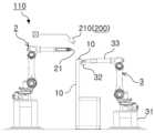
도 2는, 본 실시 예에 의한 비전인식기반 조선기자재 철의장품 형상조립 및 용접 자동화 시스템을 구성하는 로봇용접장치를 보인 개략 예시도.
도 3은, 본 실시 예에 의한 비전인식기반 조선기자재 철의장품 형상조립 및 용접 자동화 시스템을 구성하는 로봇용접장치를 보인 개략 평면 예시도.
도 4는, 본 실시 예에 의한 비전인식기반 조선기자재 철의장품 형상조립 및 용접 자동화 시스템의 전기적 연결관계를 보인 개략 예시도.
도 5는, 본 실시 예에 의한 비전인식기반 조선기자재 철의장품 형상조립 및 용접 자동화 시스템에 적용되는 비전인식수단의 비전인식처리과정을 보인 개략 예시도.
도 6은, 본 실시 예에 의한 비전인식기반 조선기자재 철의장품 형상조립 및 용접 자동화 시스템이 적용된 공정에서 피용접물을 비전인식하는 예시를 보인 개략 예시도.
도 7은, 본 실시 예에 의한 비전인식기반 조선기자재 철의장품 형상조립 및 용접 자동화 시스템의 인프라데이터통합과정을 통해 구성되는 로봇용접설비들 사이의 정보연계를 보인 개략 예시도.Figure 1 is a schematic illustration showing a vision recognition-based shipbuilding equipment steel equipment shape assembly and welding automation system according to an embodiment of the present invention.
Figure 2 is a schematic illustration showing a robot welding device that constitutes a vision recognition-based shipbuilding equipment steel equipment shape assembly and welding automation system according to this embodiment.
Figure 3 is a schematic plan illustration showing a robot welding device constituting a vision recognition-based shipbuilding equipment steel equipment shape assembly and welding automation system according to this embodiment.
Figure 4 is a schematic illustration showing the electrical connection relationship of the vision recognition-based shipbuilding equipment steel fitting shape assembly and welding automation system according to this embodiment.
Figure 5 is a schematic example diagram showing the vision recognition processing process of the vision recognition means applied to the vision recognition-based shipbuilding equipment iron fittings shape assembly and welding automation system according to this embodiment.
Figure 6 is a schematic diagram showing an example of vision recognition of a welded object in a process to which the vision recognition-based shipbuilding equipment steel equipment shape assembly and welding automation system according to this embodiment is applied.
Figure 7 is a schematic example showing the information linkage between robot welding equipment configured through the infrastructure data integration process of the vision recognition-based shipbuilding equipment iron fitting shape assembly and welding automation system according to this embodiment.
이하, 첨부된 도면을 참조하여, 본 발명에 따른 바람직한 실시 예에 의한 비전인식기반 조선기자재 철의장품 형상조립 및 용접 자동화 시스템을 상세히 설명하면 다음과 같다.Hereinafter, with reference to the attached drawings, a vision recognition-based shipbuilding equipment steel equipment shape assembly and welding automation system according to a preferred embodiment according to the present invention will be described in detail as follows.
본 발명의 실시 예는 여러 가지 형태로 변형될 수 있으며, 본 발명의 범위가 아래에서 상세히 설명하는 실시 예로 한정되는 것으로 해석되어서는 안 된다. 본 실시예는 당 업계에서 평균적인 지식을 가진 자에게 본 발명을 더욱 완전하게 설명하기 위해서 제공되는 것이다. 따라서 도면에서의 요소의 형상 등은 보다 명확한 설명을 강조하기 위해서 과장되어 표현될 수 있다. 각 도면에서 동일한 부재는 동일한 참조부호로 도시한 경우가 있음을 유의하여야 한다. 본 발명의 요지를 불필요하게 흐릴 수 있다고 판단되는 공지 기능 및 구성에 대한 상세한 기술은 생략된다.Embodiments of the present invention may be modified in various forms, and the scope of the present invention should not be construed as being limited to the embodiments described in detail below. This example is provided to more completely explain the present invention to those with average knowledge in the art. Therefore, the shapes of elements in the drawings may be exaggerated to emphasize a clearer description. It should be noted that identical members in each drawing may be indicated by the same reference numerals. Detailed descriptions of well-known functions and configurations that are judged to unnecessarily obscure the gist of the present invention are omitted.
도 1 내지 도 7은, 본 발명에 따른 일 실시 예에 의한 비전인식기반 조선기자재 철의장품 형상조립 및 용접 자동화 시스템(1)을 보인 도면으로, 본 실시 예에 의한 비전인식기반 조선기자재 철의장품 형상조립 및 용접 자동화 시스템(1)은, 선박의 건조시에 선박을 구성하는 조선기자재 철의장품을 용접조립하도록 시설된 로봇용접설비(100)에서 형상조립(가용접)과 용접조립(본용접)을 연속적으로 바로 수행하도록 되어 작업공정의 자동화를 구현하도록 된 것으로, 특히, 다품종 소량 생산이 수행되는 선박의 조선기자재 철의장품을 전기에너지를 사용하여 용접전류, 용접전압의 제어를 통해 용접하는 전기용접조립하는 것에 적합하게 적용된다.1 to 7 are diagrams showing the vision recognition-based shipbuilding equipment iron fitting shape assembly and welding automation system (1) according to an embodiment of the present invention, and the vision recognition-based shipbuilding equipment iron fitting shape according to this embodiment. The assembly and welding automation system (1) performs shape assembly (temporary welding) and welding assembly (main welding) at the robot welding facility (100), which is equipped to weld and assemble the shipbuilding equipment and iron fittings that make up the ship during ship construction. It is designed to be carried out continuously and immediately to realize automation of the work process. In particular, electric welding assembly is used to weld shipbuilding equipment and iron fittings of ships where small quantity production of various products is performed by controlling the welding current and welding voltage using electric energy. It is applied appropriately to what is being done.
즉, 다품종 소량 생산에 의한 선박의 각각의 조선기자재 철의장품들에 각각 맞춤되는 용접솔루션을 실시간으로 제공하여 적합한 용접공정을 실시간으로 수행하도록 됨에 따라, 작업성 및 작업품질을 극대화하는 것에 적합하게 적용된다.In other words, it is suitable for maximizing workability and work quality by providing a welding solution tailored to each shipbuilding equipment and iron fittings of the ship through small quantity production of a variety of products in real time and performing the appropriate welding process in real time. do.
이러한 본 실시 예에 의한 비전인식기반 조선기자재 철의장품 형상조립 및 용접 자동화 시스템(1)은, 피용접물(10)인 철의장품의 도면정보를 가지는 피용접물도면데이터와 피용접물의 형상을 인식하여 얻는 형상데이터를 포함하는 피용접물데이터를 생성하는 피용접물데이터생성과정(S100)과, 피용접물(10)의 형상조립공정에 필요한 형상조립용접물의 정보를 가지는 형상조립정보데이터를 로드(Load)하는 형상조립정보데이터로드과정(S200)과, 피용접물(10)인 철의장품의 피용접물데이터와 형상조립용접물의 정보를 가지는 형상조립정보데이터를 기반으로 연산하여 형상조립을 위한 로봇용접장치(110)의 형상조립이송정보를 포함하는 형상조립공정데이터를 생성하도록 된 형상조립공정데이터생성과정(S300)과, 형상조립된 피용접물(10)의 용접작업을 수행할 경로인 용접선을 검출하여 얻는 검출된 용접선검출데이터를 기반으로 연산하여 상기 로봇용접장치(110)의 용접이송정보를 포함하는 용접공정데이터를 생성하도록 된 용접공정데이터생성과정(S400)을 포함한다.The vision recognition-based shipbuilding equipment steel equipment shape assembly and
즉, 상기 피용접물데이터생성과정(S100)과 상기 형상조립정보데이터로드과정(S200)과 상기 형상조립공정데이터생성과정(S300)과 상기 용접공정데이터생성과정(S400)을 순차적으로 수행하여, 선박의 건조과정에서 선박을 구성하는 조선기자재(철의장품)의 용접제조시 로봇용접장치(110)를 통해 자동화 작업시스템을 구현하게 된다.That is, the welded object data generation process (S100), the shape assembly information data loading process (S200), the shape assembly process data generation process (S300), and the welding process data generation process (S400) are sequentially performed, During the construction process, an automated work system is implemented through the
이에 따라, 용접하고자 하는 각각의 새로운 피용접물(10)마다 상기 로봇용접장치(110)의 작업 교시를 수동으로 티칭(로봇의 작업 동작 공정을 프로그래밍)하지 않고도 사용할 수 있게 되어, 로봇용접작업의 사용성이 증대되고 티칭에 대한 고비용의 유지보수가 발생하지 않아 경제성이 극대화된다.Accordingly, the work teachings of the
상기에서 로봇용접장치(110)는, 전원공급부(42)의 전원을 제어하도록 된 로봇용접제어수단(41)의 제어를 통해 전원을 공급받아 용접기(21)를 선택된 이동좌표로 이동시킨 후, 상기 용접기(21)를 구동하여 이동된 좌표에서 용접작업을 수행하도록 된 로봇용접수단(2)과; 상기 로봇용접수단(2)의 이동좌표에 배치되며 피용접물(10)을 고정하고 선택된 방향을 정역회전시켜 원하는 용접부위에 대한 방향을 전환할 수 있도록 된 고정수단(3);을 포함할 수 있다.In the above, the
즉, 상기 로봇용접수단(2)과 상기 고정수단(3)이 작업공간에 각각 배치된 상태에서, 상기 고정수단(3)에 상기 피용접물(10)을 고정한 후, 용접(본용접) 작업을 원활히 수행하도록 용접을 진행할 피용접물(10)들이 서로 용접되는 정위치에서 어긋나지 않게 수행하는 형상조립(가용접) 작업을 상기 제어수단(41)의 제어와 상기 형상조립공정데이터에 따라 상기 피용접물(10)의 형상조립(가용접) 부위를 선택적으로 방향전환하여 상기 용접기(21)에 맞춤되게 위치시킨 후, 상기 제어수단(41)의 제어를 통해 상기 용접기(21)를 구동하여 상기 피용접물(10)에 대한 형상조립(가용접) 작업을 수행하게 될 수 있다.That is, in a state where the robot welding means 2 and the fixing means 3 are respectively arranged in the work space, the object to be welded 10 is fixed to the fixing means 3, and then the welding (main welding) operation is performed. To ensure that the welded
아울러, 형상조립 작업을 수행한 이후, 상기 용접공정데이터에 따른 상기 피용접물(10)의 용접부를 선택적으로 방향전환하여 상기 용접기(21)에 맞춤되게 위치시킨 후, 상기 제어수단(41)의 제어를 통해 상기 용접기(21)를 구동하여 상기 피용접물(10)에 대한 용접작업을 수행하게 될 수 있다.In addition, after performing the shape assembly operation, the direction of the welded part of the welded
상기에서 로봇용접수단(2)의 구성 및 구조는, 용접작업을 수행하도록 된 상기 용접기(21)가 구비된 로봇의 관절프레임이 다수 개의 '서보모터'를 통해 정밀한 위치 이동이 가능하도록 되며 사용자에 의해 조작되는 '로봇컨트롤러'의 제어에 의해 상기 서보모터들을 제어하도록 구성될 수 있는 것으로, 종래 공지된 기술들 중에서 사용자에 의해 선택된 구성 및 구조가 적합하게 적용될 수 있다.The configuration and structure of the robot welding means (2) in the above is such that the joint frame of the robot equipped with the welder (21) to perform the welding work is capable of precise positional movement through a plurality of 'servomotors', allowing the user to It can be configured to control the servomotors by controlling a 'robot controller' operated by a robot, and a configuration and structure selected by the user among conventionally known technologies can be appropriately applied.
상기에서 고정수단(3)은, 작업공간의 바닥에 시설되는 프레임구조체로 이루어지는 장치본체(31)와; 상기 피용접물(10)의 단부를 끼움하여 지지하도록 형성된 고정부재(32)와; 상기 로봇용접제어수단(41)의 제어를 통해 구동되며 일부위에 상기 고정부재(32)가 고정구비되고 상기 고정부재(32)에 끼움지지된 피용접물(10)을 제어에 의해 회전시키도록 된 로봇암장치(33);를 포함할 수 있다. In the above, the fixing means (3) includes an apparatus body (31) made of a frame structure installed on the floor of the work space; A fixing
즉, 상기 피용접물(10)이 상기 고정부재(32)에 일단이 고정된 상태에서 상기 형상조립공정데이터를 기반으로 하는 상기 로봇용접제어수단(41)의 제어를 통해 상기 로봇암장치(33)에 고정구비된 상기 고정부재(32)를 정역회전하여 상기 피용접물(10)의 형상조립 부위의 위치를 선택적으로 전환하면서 형상조립 작업을 수행하게 될 수 있다.That is, with one end of the welded
아울러, 형상조립(가용접) 작업을 수행한 이후, 상기 용접공정데이터를 기반으로 기반으로 하는 상기 로봇용접제어수단(41)의 제어에 의한 상기 로봇암장치(33)의 회전구동을 통해 형상조립(가용접)된 피용접물(10)에 대한 공간좌표의 전환과 상기 로봇용접수단(2)의 용접기(21)에 대한 이동좌표의 전환을 복합적으로 연산수행하여 상기 피용접물(10)의 용접작업에 대한 3차원공간좌표를 구현하게 될 수 있어, 각각의 개별적 형상과 크기를 가지는 피용접물(10)의 용접작업에 대한 자동화를 맞춤되게 구현하게 될 수 있다.In addition, after performing the shape assembly (tack welding) work, shape assembly is performed through rotational drive of the
이에 따라, 조선기자재 철의장품을 상기 고정수단(3)에 의한 회전을 통해 3차원 형태의 조립작업을 진행할 수 있게 된다.Accordingly, it is possible to assemble the shipbuilding equipment steel equipment into a three-dimensional shape by rotating it using the fixing means 3.
따라서, 다양한 조선기자재(철의장품)들에 대하여 각각 맞춤되는 자동용접을 수행할 수 있어, 선박의 제조에 대한 자동화공정을 통해 구현하고, 생산효율을 향상시키며, 불량을 제거하여 제조품질을 증대하게 될 수 있다.Therefore, customized automatic welding can be performed for various shipbuilding equipment (iron equipment), which can be implemented through an automated process for ship manufacturing, improves production efficiency, and increases manufacturing quality by eliminating defects. It can be.
상기에서 고정부재(32)는, 형상조립을 위해 가공된 다양한 피용접물(앵글, 잔넬, H빔, PIPE 등)의 규격에 따라 알맞은 클램핑 구조를 가지면서 형성되어 상기 로봇암장치(33)에 탈부착가능하면서 고정구비되도록 구성될 수 있는 것으로, 종래 공지된 기술들 중에서 사용자에 의해 선택된 구성 및 구조가 적합하게 적용될 수 있다.In the above, the fixing
이와 같이 이루어지는 본 실시 예에 의한 비전인식기반 조선기자재 철의장품 형상조립 및 용접 자동화 시스템(1)에서, 상기 형상조립공정데이터생성과정(S300)에서 생성되는 상기 형상조립공정데이터는, 각기 다른 피용접물(10)들에 대한 '형상조립의 우선 순위'데이터를 더 포함할 수 있으며; 상기 '형상조립의 우선 순위'데이터는, 상기 형상조립정보데이터와 상기 피용접물데이터를 기반으로 연산하여 '우선 순위'를 지정할 수 있다.In the vision recognition-based shipbuilding equipment steel equipment shape assembly and welding automation system (1) according to this embodiment configured as described above, the shape assembly process data generated in the shape assembly process data generation process (S300) is different from each other to be welded. (10) may further include 'priority of shape assembly' data; The 'priority of shape assembly' data may be calculated based on the shape assembly information data and the welded object data to designate a 'priority'.
즉, 조선기자재 철의장품(피용접물)의 조립 중에 각기 다른 피용접물(10)들의 크기와 무게 의해 발생될 수 있는 'Turn Over'와 같은 조립사고를 방지하고 안전성을 향상시키기 위해 용접 대상이 되는 피용접물(10)의 무게, 길이, 전체적인 크기를 고려하여 형상조립의 공정 순서를 지정할 수 있다.In other words, in order to prevent assembly accidents such as 'Turn Over' that may occur due to the size and weight of different welded objects (10) during the assembly of shipbuilding equipment iron fittings (welded objects) and to improve safety, the welded objects are The shape assembly process sequence can be specified by considering the weight, length, and overall size of the
일 예로, 조립 중에 'Turn Over'의 사고 발생에 대한 안전성을 고려하면 피용접물(10)의 무게 중심이 바닥에 대하여 가깝게 하여야 하며, 이에 따라 조립과정의 1순위로 형강재(피용접물)의 무게가 제일 무거운 것, 2순위로 형강재(피용접물)의 길이가 제일 긴 것, 3순위로 형강재(피용접물)의 전체적인 크기가 제일 큰 것을 우선으로 하여 조립하도록 하고, 그것에 해당되지 않는 형강재(피용접물)들은 설계된 모델링의 순서대로 조립하도록 공정과정을 연산하여 도출할 수 있다.For example, considering safety against 'Turn Over' accidents during assembly, the center of gravity of the welded
한편, 본 실시 예에 의한 비전인식기반 조선기자재 철의장품 형상조립 및 용접 자동화 시스템(1)에서, 상기 피용접물데이터생성과정(S100)의 상기 피용접물도면데이터는, 피용접물(10)인 철의장품의 용접 자동화공정설비를 종합적으로 관리하는 공정종합관리서버(400)에 저장된 도면정보를 통신망(300)을 통해 내려받아 로드(Load)하여 생성되고; 상기 피용접물데이터생성과정(S100)의 상기 형상데이터는, 비전인식수단(200)을 통해 피용접물(10)을 다각도로 촬영하여 얻어진 '2차원 이미지'들을 기반으로 연산하여 3차원 형태로 형상화된 '3차원 사물'로 생성된다.Meanwhile, in the vision recognition-based shipbuilding equipment steel equipment shape assembly and
즉, 피용접물(10)인 철의장품이 생산 및 가공되는 철의장 업체에서 제작된 철의장품의 도면정보를 철의장 업체에서 상기 공정종합관리서버(400)에 전송하여 저장하면, 철의장품의 용접작업에 필요한 철의장품(피용접물)의 도면정보를 로봇용접설비가 시설된 로봇용접공장에서 상기 공정종합관리서버(400)에 접속하여 내려받아 로드(Load)하여 사용할 수 있게 된다.In other words, when the steel fitting company transmits and stores the drawing information of the iron fitting manufactured by the iron fitting company where the iron fitting, which is the welded
아울러, 상기 비전인식수단(200)을 통해 실제로 용접작업을 진행할 상기 고정수단에 고정된 피용접물(10)을 촬영하여 '3차원 사물'의 데이터로 생성하여 상기 피용접물도면데이터의 형상을 기반으로 실제로 고정된 피용접물(10)의 형상과의 오차를 교정할 수 있게 된다.In addition, through the vision recognition means 200, the welded
이에 따라, 피용접물(10) 크기 및 위치에 따른 오차에 대한 용접 불량을 제거하여 제조품질을 증대하게 될 수 있다.Accordingly, manufacturing quality can be increased by eliminating welding defects due to errors depending on the size and position of the welded
상기에서 로봇용접설비(100)는, 상기 로봇용접장치(110)와, 상기 로봇용접장치(110)가 수행하는 용접공정을 제어하도록 구성된 메인제어부(120)와, 상기 메인제어부(120)의 제어를 통해 통신망(300)에 접속가능하도록 구성된 메인통신부(130)를 포함한다.In the above, the
즉, 상기 로봇용접설비(100)는 로봇용접공장의 작업공간에 시설되되, 피용접물(10)의 형상조립 및 용접 공정을 제어하는 메인제어부(120)의 제어에 의해 상기 로봇용접장치(110)가 피용접물(10)의 형상조립 및 용접 작업을 수행하고, 상기 메인통신부(130)를 통해 용접공정에 필요한 데이터를 통신망(300)을 통해 제공받도록 구성하여 철의장품(피용접물)에 대한 용접공정을 수행하는 하나의 플랫폼 단위로 구성될 수 있게 된다.That is, the
상기에서 피용접물도면데이터를 구성하는 피용접물(10)의 정보는, 기존의 다양한 각각의 조선기자재(철의장품)의 형상(주로, I, ㄱ, ㄷ, ㄲ, T 형 등)에 따른 피용접물(10)의 높이 및 너비, 부재 재질, 두께 등이 포함될 수 있다.In the above, the information on the welded
상기에서 형상조립정보데이터로드과정(S200)의 상기 형상조립정보데이터는, 피용접물(10)인 철의장품의 용접 자동화공정설비를 종합적으로 관리하는 공정종합관리서버(400)에 저장된 형상조립정보를 통신망(300)을 통해 내려받아 로드(Load)하여 생성된다.In the above, the shape assembly information data in the shape assembly information data loading process (S200) is the shape assembly information stored in the process
즉, 피용접물(10)인 철의장품(피용접물)이 용접된 용접물의 설계정보를 용접공정을 진행하기 이전에 상기 공정종합관리서버(400)에 전송하여 저장하고, 피용접물(10)의 용접공정을 수행할 때 통신망(300)을 통해 로봇용접설비(100)가 시설된 로봇용접공장에서 상기 공정종합관리서버(400)에 접속하여 철의장품의 형상조립에 필요한 형상조립정보를 내려받아 로드(Load)하여 사용하도록 구성할 수 있다.In other words, the design information of the welded product (the welded object), which is the welded
이에 따라, 용접공정을 수행할 때마다 용접물의 설계자에게 도면을 별도로 제공받지 않고도 형상조립(가용접)에 필요한 설계정보를 추출할 수 있게 된다.Accordingly, it is possible to extract the design information required for shape assembly (tack welding) without separately receiving drawings from the designer of the welded product each time a welding process is performed.
상기와 같이 이루어지는 본 실시 예에 의한 비전인식기반 조선기자재 철의장품 형상조립 및 용접 자동화 시스템(1)에서, 상기 용접공정데이터를 생성시 기반이 되는 상기 용접선검출데이터는, 상기 비전인식수단(200)을 통해 피용접물(10)의 특이점들을 검출하여 라인(Line)형상의 경로로 인식하고 추적해서 분석된 용접선 경로 정보로 이루어지도록 생성된다.In the vision recognition-based shipbuilding equipment steel equipment shape assembly and
즉, 상기 용접공정데이터생성과정(S400)에 의해 용접(본용접) 작업 동작 공정을 가지는 용접공정데이터를 생성하는 과정에서, 상기 용접공정데이터를 구성하는 상기 로봇용접장치(100)의 용접이송정보(용접경로)를 연산할 때 필요한 용접선 경로를 상기 비전인식수단(200)을 통해 검출시킬 수 있게 된다.That is, in the process of generating welding process data having a welding (main welding) work operation process by the welding process data generation process (S400), welding transfer information of the
이에 따라, 상기 용접공정데이터를 생성할 때 용접 경로의 불량을 제거하면서 다양한 조선기자재(철의장품)들에 대하여 각각 맞춤되는 자동용접을 수행하게 될 수 있다.Accordingly, when generating the welding process data, it is possible to perform customized automatic welding for various shipbuilding equipment (iron equipment) while eliminating defects in the welding path.
상기에서 용접공정데이터를 구성하는 용접이송정보는, 로봇용접장치(110)가 용접을 하기 위해 이동되어야 하는 좌표, 이동속도, 회전 각도 등이 포함될 수 있다.The welding transfer information constituting the welding process data above may include coordinates, movement speed, rotation angle, etc. at which the
상기에서 비전인식수단(200)은, 상기 로봇용접설비(100)가 시설되는 작업공간에 구비되며 상기 로봇용접장치(100)의 상기 로봇용접제어수단(41)의 제어신호에 의해 사물을 카메라 촬영하여 영상이미지를 생성하는 비전카메라모듈(210)과, 상기 비전카메라모듈(210)에서 촬영된 영상이미지를 분석하여 피용접물(10)의 형상과 용접가공부분을 추출하는 이미지분석부(220)와, 상기 비전카메라모듈(210)에서 촬영된 영상이미지를 상기 메인통신부(130)를 통해 통신망(300)을 거쳐 전송받으며 영상이미지를 상기 이미지분석부(220)로 보내고 상기 이미지분석부(220)에서 추출된 피용접물(10)의 형상과 용접가공부분을 기반으로 상기 로봇용접장치(110)의 용접이송정보를 연산하여 상기 로봇용접설비(100)로 송신하는 비전프로세싱서버(230)를 포함하며; 상기 비전프로세싱서버(230)와 상기 이미지분석부(220)는, 통신망(300)을 통해 인터넷 기반으로 컴퓨터 시스템 리소스를 제공하도록 구성된 클라우드컴퓨팅서버(500)에 설치되어 운용될 수 있다.In the above, the vision recognition means 200 is provided in the work space where the
즉, 상기 메인제어부(120)에서 용접공정을 수행하기 위해 상기 비전인식수단(200)을 통해 피용접물(10)을 촬영하여 피용접물의 형상과 용접선을 검출하여 형상조립이송정보와 용접이송정보를 연산할 때, 상기 메인제어부(120)가 상기 비전인식수단(200)의 상기 비전인식카메라모듈(210)에 비전인식을 시도하는 비전인식제어신호를 송신하여 상기 비전카메라모듈(210)의 촬영준비(초기화)를 진행한다.That is, in order to perform the welding process in the
그리고, 촬영을 하여 생성된 영상이미지를 상기 로봇용접설비(100)가 시설된 각각의 로봇용접공장에서가 아닌 상기 클라우드컴퓨팅서버(500)의 상기 비전프로세싱서버(230)로 전송하며, 전송된 영상이미지를 상기 이미지분석부(220)에서 분석하게 된다.In addition, the video image generated by filming is transmitted to the
아울러, 영상이미지를 분석하여 추출된 피용접물(10)의 형상, 용접가공부분등의 정보를 기반으로 상기 비전프로세싱서버(230)에서 상기 로봇용접장치가 수행할 용접공정에 대한 용접이송정보, 형상조립이송정보가 연산되어 생성된다.In addition, welding transfer information and shape for the welding process to be performed by the robot welding device in the
상기와 같이 연산된 용접공정에 필요한 정보들을 상기 메인통신부(130)로 송신하여 상기 메인통신부(130)와 전기적으로 연결된 상기 메인제어부(120)에서 송신된 정보들을 기반으로 상기 로봇용접장치의 제어연산을 수행하여 용접공정을 진행하게 된다.The information required for the welding process calculated as above is transmitted to the
또한, 조선기자재(철의장품)의 용접공정을 수행하는 로봇용접설비(100)를 다수의 로봇용접공장(플랫폼)들의 형태로 운용할 때, 초기 설치비용이 많이 들고 다중으로 설치시 유지보수가 어려운 비전인식을 수행하는 상기 비전인신수단(200)의 상기 이미지분석부(220)와 같은 컴퓨팅설비를 단일의 설비로 설치하여 적용할 수 있게 된다.In addition, when the
이에 따라, 유지보수성과 확장성 및 경제성이 증대하는 효과를 가진다.Accordingly, maintainability, scalability, and economic efficiency are increased.
상기에서 비전카메라모듈(210)은, 사물을 카메라 촬영하여 이미지를 생성하는 '카메라모듈'로 구성 및 구조될 수 있는 것으로, 종래 공지된 기술들 중에서 사용자에 의해 선택된 구성 및 구조가 적합하게 적용될 수 있다.In the above, the
이와 같이 이루어지는 본 실시 예에 의한 비전인식기반 조선기자재 철의장품 형상조립 및 용접 자동화 시스템(1)은, 각각의 피용접물(10)에 대한 상기 형상조립공정데이터와 상기 용접공정데이터에 의해 수행되는 상기 로봇용접장치(110)의 용접공정에서, 형상조립 및 용접공정 과정을 기록하는 로깅(logging)에서 추출 할 수 있는 '용접물제품 형상', 비드형상, 용접공정에 적용된 용접전류 및 용접전압 파형, 용접제조물 산출량, '용접제조물 품질' 정보를 포함하는 인프라데이터를 실시간으로 공정종합관리서버(400)로 전송하는 인프라데이터통합과정(S500);을 더 포함한다.The vision recognition-based shipbuilding equipment steel equipment shape assembly and
즉, 상기 인프라데이터통합과정(S500)을 통해 로봇용접공장에 시설되는 본 실시 예에 의한 비전인식기반 조선기자재 철의장품 형상조립 및 용접 자동화 시스템(1)이 적용된 각각의 공정들이 상기 종합공정관리서버(400)에 접속하여 로봇용접공장의 공정에서 생성되는 인프라데이터를 전송하고, 상기 종합관리서버(400)에 전송된 타 공정에서 진행했던 용접공정 과정의 인프라데이터를 누적시키면서 저장하게 되며, 이후 추가로 시설되는 타 로봇용접공장과 통신망(300)을 통해 상기 종합공정관리서버(400)에 접속해서 인프라데이터를 내려받는 정보교환 과정을 통해 정보연계를 효율적으로 구현하게 된다.That is, through the infrastructure data integration process (S500), each process to which the vision recognition-based shipbuilding equipment steel equipment shape assembly and welding automation system (1) according to this embodiment installed in the robot welding factory is applied is connected to the comprehensive process management server. By connecting to (400), the infrastructure data generated in the process of the robot welding factory is transmitted, and the infrastructure data of the welding process carried out in other processes transmitted to the general management server (400) is accumulated and stored, and added later. Information linkage is efficiently implemented through an information exchange process of downloading infrastructure data by connecting to the comprehensive
이에 따라, 실시간 양방향 정보 전달 및 저장이 가능하도록 시스템을 구성할 수 있으며, 상기 피용접물(10)의 용접부에서 추출 할 수 있는 비드형상, 용접전류/전압 파형, 생산성 등을 포함하고 용접 자동화 사양개발 및 확장을 위한 인프라데이터의 확보가 가능하게 되며, 상기 공정종합관리서버(400)를 중심으로 로봇용접공장 사이의 네트워크 협업이 가능하게 된다.Accordingly, the system can be configured to enable real-time two-way information transmission and storage, and includes the bead shape, welding current/voltage waveform, productivity, etc. that can be extracted from the weld zone of the welded
이에 따라, 용접공정 과정 중과 후에 취득 가능한 용접공정데이터의 선정 및 로깅작업과, 용접공정/품질 분석 및 용접전류/전압/비드형상 저장 기능의 수행과, 로봇 용접 자동화 시스템 연계를 위한 주요 모듈간 통신체계 수립될 수 있어, 이를 통해 클라우드 기반 용접품질 관리 스마트 시스템의 구현될 수 있으며, 추후 품질 생산관리와 용접 품질 저하와 관련된 요소를 파악할 수 있도록 피드백이 가능하게 실현될 수 있다.Accordingly, selection and logging of welding process data that can be acquired during and after the welding process, performance of welding process/quality analysis and welding current/voltage/bead shape storage functions, and communication between major modules for linking with the robot welding automation system A system can be established, through which a cloud-based welding quality management smart system can be implemented, and feedback can be realized to identify factors related to quality production management and welding quality decline in the future.
또한, 상기 비전인식수단(200)과 같은 사물을 인식하고 검출하는 비전 시스템을 활용하여 생성된 피용접물 및 용접물을 대상으로 용접 자동화공정을 로깅한 것을 상기 공정종합관리서버(400)에 지속적으로 저장함으로써, 저장된 용접공정시 발생된 용접불량의 상황들을 인공지능을 통해 학습하여 피용접부(10)의 용접부를 학습된 비전 시스템을 통해 보다 정확한 위치로 검출하도록 정밀도를 보정할 수 있는 데이터를 확보할 수 있게 된다.In addition, logging of the welding automation process for welded objects and welded objects created using a vision system that recognizes and detects objects such as the vision recognition means 200 is continuously stored in the process
이에 따라, 용접부 예측을 통한 품질 분석 및 개선 활동이 이루어지고 실패 비용이 저감되어 경제성이 증대된다.Accordingly, quality analysis and improvement activities are carried out through weld zone prediction, and failure costs are reduced, thereby increasing economic efficiency.
이상에서 설명된 본 발명의 일 실시 예는 예시적인 것에 불과하며, 본 발명이 속한 기술분야의 통상의 지식을 가진 자라면 이로부터 다양한 변형 및 균등한 타 실시 예가 가능하다는 점을 잘 알 수 있을 것이다. 그러므로 본 발명은 상기의 상세한 설명에서 언급되는 형태로만 한정되는 것은 아님을 잘 이해할 수 있을 것이다. 따라서 본 발명의 진정한 기술적 보호 범위는 첨부된 특허청구범위의 기술적 사상에 의해 정해져야 할 것이다. 또한, 본 발명은 첨부된 청구범위에 의해 정의되는 본 발명의 정신과 그 범위 내에 있는 모든 변형물과 균등물 및 대체물을 포함하는 것으로 이해되어야 한다.One embodiment of the present invention described above is merely illustrative, and those skilled in the art will be able to appreciate that various modifications and other equivalent embodiments are possible. . Therefore, it will be understood that the present invention is not limited to the forms mentioned in the detailed description above. Therefore, the true scope of technical protection of the present invention should be determined by the technical spirit of the attached patent claims. In addition, the present invention should be understood to include all modifications, equivalents and substitutes within the spirit and scope of the present invention as defined by the appended claims.
1 : 조선기자재 철의장품 형상조립 및 용접 자동화 시스템
10 : 피용접물100 : 로봇용접설비
110 : 로봇용접장치120 : 메인제어부
130 : 메인통신부200 : 비전인식수단
210 : 비전카메라모듈220 : 이미지분석부
230 : 비전프로세싱서버
300 : 통신망400 : 공정종합관리서버
500 : 클라우드컴퓨팅서버
2 : 로봇용접수단21 : 용접기
3 : 고정수단31 : 장치본체
32 : 고정부재33 : 로봇암장치
41 : 로봇용접제어수단42 : 전원공급부1: Shipbuilding equipment steel fitting shape assembly and welding automation system
10: Welded object 100: Robot welding equipment
110: Robot welding device 120: Main control unit
130: Main communication unit 200: Vision recognition means
210: Vision camera module 220: Image analysis unit
230: Vision processing server
300: Communication network 400: Process comprehensive management server
500: Cloud computing server
2: Robot welding means 21: Welder
3: Fixing means 31: Device body
32: fixing member 33: robot arm device
41: Robot welding control means 42: Power supply unit
Claims (2)
Translated fromKorean피용접물(10)인 철의장품의 도면정보를 가지는 피용접물도면데이터와 피용접물(10)의 형상을 인식하여 얻는 형상데이터를 포함하는 피용접물데이터를 생성하는 피용접물데이터생성과정(S100)과, 피용접물(10)의 형상조립공정에 필요한 형상조립용접물의 정보를 가지는 형상조립정보데이터를 로드(Load)하는 형상조립정보데이터로드과정(S200)과, 피용접물(10)인 철의장품의 피용접물데이터와 형상조립용접물의 정보를 가지는 형상조립정보데이터를 기반으로 연산하여 형상조립을 위한 로봇용접장치(110)의 형상조립이송정보를 포함하는 형상조립공정데이터를 생성하도록 된 형상조립공정데이터생성과정(S300)과, 형상조립된 피용접물(10)의 용접작업을 수행할 경로인 용접선을 검출하여 얻는 검출된 용접선검출데이터를 기반으로 연산하여 상기 로봇용접장치(110)의 용접이송정보를 포함하는 용접공정데이터를 생성하도록 된 용접공정데이터생성과정(S400)을 포함하며;
상기 피용접물데이터생성과정(S100)의 상기 피용접물도면데이터는,
피용접물(10)인 철의장품의 용접 자동화공정설비를 종합적으로 관리하는 공정종합관리서버(400)에서 통신망(300)을 통해 내려받아 로드(Load)하여 생성되고;
상기 피용접물데이터생성과정(S100)의 상기 형상데이터는,
비전인식수단(200)을 통해 피용접물(10)을 다각도로 촬영하여 얻어진 '2차원 이미지'들을 기반으로 연산하여 3차원 형태로 형상화된 '3차원 사물'로 생성되며;
상기 로봇용접장치(110)는,
전원공급부(42)의 전원을 제어하도록 된 로봇용접제어수단(41)의 제어를 통해 전원을 공급받아 용접기(21)를 선택된 이동좌표로 이동시킨 후, 상기 용접기(21)를 구동하여 이동된 좌표에서 용접작업을 수행하도록 된 로봇용접수단(2)과; 상기 로봇용접수단(2)의 이동좌표에 배치되며 피용접물(10)을 고정하고 선택된 방향을 정역회전시켜 원하는 용접부위에 대한 방향을 전환할 수 있도록 된 고정수단(3)을 포함하되;
상기 고정수단(3)은,
작업공간의 바닥에 시설되는 프레임구조체로 이루어지는 장치본체(31)와; 상기 피용접물(10)의 단부를 끼움하여 지지하도록 형성된 고정부재(32)와; 상기 로봇용접제어수단(41)의 제어를 통해 구동되며 일부위에 상기 고정부재(32)가 고정구비되고 상기 고정부재(32)에 끼움지지된 피용접물(10)을 제어에 의해 회전시키도록 된 로봇암장치(33)를 포함하며;
상기 로봇용접장치(110)의 용접공정에서 형상조립(가용접) 작업 과정은,
상기 형상조립공정데이터를 기반으로 상기 로봇용접제어수단(41)의 제어를 통해 상기 고정부재(32)를 정역회전하여 상기 피용접물(10)의 형상조립 부위의 위치를 선택적으로 전환해서 상기 용접기(21)에 맞춤되게 위치시킨 후, 상기 용접기(21)를 구동하여 상기 피용접물(10)에 대한 형상조립(가용접) 작업을 수행하고;
상기 로봇용접장치(110)의 용접공정에서 용접(본용접) 작업 과정은,
상기 용접공정데이터를 기반으로 하는 상기 로봇용접제어수단(41)의 제어에 의한 상기 로봇암장치(33)의 회전구동을 통해 형상조립(가용접)된 피용접물(10)에 대한 공간좌표의 전환과 상기 로봇용접수단(2)의 용접기(21)에 대한 이동좌표의 변환을 복합적으로 연산수행하여 상기 피용접물(10)의 용접(본용접) 작업에 대한 3차원공간좌표를 구현해서 상기 피용접물(10)의 개별적 형상과 크기에 맞춤되게 상기 피용접물(10)의 용접부를 상기 용접기(21)에 맞춤되게 위치시킨 후, 상기 용접기(21)를 구동하여 상기 피용접물(10)에 대한 용접(본용접) 작업을 수행하며;
각각의 피용접물(10)에 대한 상기 형상조립공정데이터와 상기 용접공정데이터에 의해 수행되는 상기 로봇용접장치(110)의 용접공정에서는,
형상조립 및 용접공정 과정을 기록하는 로깅(logging)에서 추출 할 수 있는 '용접물제품 형상', 비드형상, 용접공정에 적용된 용접전류 및 용접전압 파형, 용접제조물 산출량, '용접제조물 품질' 정보를 포함하는 인프라데이터를 실시간으로 공정종합관리서버(400)로 전송하는 인프라데이터통합과정(S500)을 더 포함하고;
상기 로봇용접설비(100)에서 형상조립(가용접) 작업과 용접조립(본용접) 작업이 연속적으로 수행되는 것을 통해 다양한 조선기자재 철의장품들에 대하여 각각 맞춤되는 자동용접이 수행되어 선박의 제조에 대한 자동화공정이 구현되는 것을 특징으로 하는 비전인식기반 조선기자재 철의장품 형상조립 및 용접 자동화 시스템.In the vision recognition-based shipbuilding equipment shape assembly and welding automation system (1), which includes a robot welding facility (100) equipped to weld and assemble the shipbuilding equipment and iron equipment that constitutes the ship during ship construction;
A welded object data generation process (S100) of generating welded object data including welded object drawing data containing drawing information of the iron fitting, which is the welded object 10, and shape data obtained by recognizing the shape of the welded object 10; A shape assembly information data loading process (S200) of loading shape assembly information data containing information on the shape assembly welded object required for the shape assembly process of the welded object 10, and the welded object of the iron fitting, which is the welded object 10. A shape assembly process data generation process to generate shape assembly process data including shape assembly transfer information of the robot welding device 110 for shape assembly by calculating based on shape assembly information data containing information on the data and shape assembly welded products. (S300) and the welding transfer information of the robot welding device 110 by calculating based on the detected welding line detection data obtained by detecting the welding line that is the path to perform the welding operation of the shape-assembled object to be welded 10. Includes a welding process data generation process (S400) designed to generate welding process data;
The welded object drawing data of the welded object data generation process (S100) is,
It is created by downloading and loading through the communication network 300 from the process management server 400, which comprehensively manages the welding automation process equipment for the iron fittings, which is the welded object 10;
The shape data of the welded material data generation process (S100) is,
A '3-dimensional object' shaped in a 3-dimensional form is generated by calculating based on '2-dimensional images' obtained by photographing the welded object 10 from various angles through the vision recognition means 200;
The robot welding device 110,
Power is supplied through the control of the robot welding control means 41, which controls the power of the power supply unit 42, and the welder 21 is moved to the selected movement coordinate, and then the welder 21 is driven to the moved coordinate. A robot welding means (2) designed to perform welding work; It includes a fixing means (3) disposed at the moving coordinate of the robot welding means (2) and capable of fixing the welded object (10) and changing the direction of the desired welding area by rotating the selected direction forward or backward;
The fixing means (3) is,
An apparatus body (31) made of a frame structure installed on the floor of the work space; A fixing member 32 formed to fit and support an end of the welded object 10; A robot that is driven through the control of the robot welding control means 41, has the fixing member 32 fixed on a part of it, and rotates the welded object 10 sandwiched by the fixing member 32 by control. It includes an arm device (33);
The shape assembly (tack welding) work process in the welding process of the robot welding device 110 is,
The welder ( 21), the welder 21 is driven to perform shape assembly (tack welding) on the welded object 10;
The welding (main welding) work process in the welding process of the robot welding device 110 is,
Conversion of spatial coordinates for the shape-assembled (tack-welded) object 10 through rotational drive of the robot arm device 33 under the control of the robot welding control means 41 based on the welding process data. and the transformation of the moving coordinates of the welder 21 of the robot welding means 2 are performed in a complex manner to implement three-dimensional space coordinates for the welding (main welding) operation of the welded object 10. After positioning the welded part of the welded object 10 in the welder 21 to suit the individual shape and size of (10), the welder 21 is driven to weld the welded object 10 ( main welding) work is performed;
In the welding process of the robot welding device 110 performed by the shape assembly process data and the welding process data for each welded object 10,
Includes 'welded product shape', bead shape, welding current and welding voltage waveform applied to the welding process, welded product yield, and 'welded product quality' information that can be extracted from logging that records the shape assembly and welding process process. It further includes an infrastructure data integration process (S500) that transmits the infrastructure data to the process comprehensive management server (400) in real time;
In the robot welding equipment 100, the shape assembly (tack welding) work and the welding assembly (main welding) work are performed continuously, so that customized automatic welding is performed on various shipbuilding equipment and iron fittings, thereby contributing to the manufacture of ships. A vision recognition-based shipbuilding equipment and iron fittings shape assembly and welding automation system, characterized by the implementation of automated processes.
Priority Applications (1)
| Application Number | Priority Date | Filing Date | Title |
|---|---|---|---|
| KR1020230064459AKR102592197B1 (en) | 2023-05-18 | 2023-05-18 | Vision recognition-based shipbuilding equipment steel fittings shape assembly and welding automation system |
Applications Claiming Priority (1)
| Application Number | Priority Date | Filing Date | Title |
|---|---|---|---|
| KR1020230064459AKR102592197B1 (en) | 2023-05-18 | 2023-05-18 | Vision recognition-based shipbuilding equipment steel fittings shape assembly and welding automation system |
Publications (1)
| Publication Number | Publication Date |
|---|---|
| KR102592197B1true KR102592197B1 (en) | 2023-10-20 |
Family
ID=88514430
Family Applications (1)
| Application Number | Title | Priority Date | Filing Date |
|---|---|---|---|
| KR1020230064459AActiveKR102592197B1 (en) | 2023-05-18 | 2023-05-18 | Vision recognition-based shipbuilding equipment steel fittings shape assembly and welding automation system |
Country Status (1)
| Country | Link |
|---|---|
| KR (1) | KR102592197B1 (en) |
Citations (7)
| Publication number | Priority date | Publication date | Assignee | Title |
|---|---|---|---|---|
| KR20050086635A (en) | 2002-11-13 | 2005-08-30 | 다 탕 모바일 커뮤니케이션즈 이큅먼트 코포레이션 리미티드 | Method for multi-user demodulation with variable spread spectrum coefficient |
| KR102034541B1 (en)* | 2018-07-10 | 2019-10-21 | 주식회사 성우하이텍 | A robot system component asssembly and control method thereof |
| KR20200085135A (en) | 2019-01-04 | 2020-07-14 | 대한민국(농림축산식품부 농림축산검역본부장) | H5N8 strain Recombinant Influenza A virus and Vaccine Composition for H5 Serotype Influenza A virus belonging to clade 2.3.4.4A comprising the same |
| KR20210037746A (en) | 2014-01-25 | 2021-04-06 | 소니 인터랙티브 엔터테인먼트 아메리카 엘엘씨 | Menu navigation in a head-mounted display |
| KR20210087831A (en)* | 2020-01-03 | 2021-07-13 | 대우조선해양 주식회사 | Portable robot operation method based on virtual sensor and 3-D mesh model |
| KR102424501B1 (en) | 2022-04-25 | 2022-07-25 | 주식회사 미주산업 | Vision recognition-based shipbuilding equipment robot welding automation system |
| KR20220147443A (en)* | 2021-04-27 | 2022-11-03 | 대우조선해양 주식회사 | Method for welding arbitrarily supported workpiece |
- 2023
- 2023-05-18KRKR1020230064459Apatent/KR102592197B1/enactiveActive
Patent Citations (7)
| Publication number | Priority date | Publication date | Assignee | Title |
|---|---|---|---|---|
| KR20050086635A (en) | 2002-11-13 | 2005-08-30 | 다 탕 모바일 커뮤니케이션즈 이큅먼트 코포레이션 리미티드 | Method for multi-user demodulation with variable spread spectrum coefficient |
| KR20210037746A (en) | 2014-01-25 | 2021-04-06 | 소니 인터랙티브 엔터테인먼트 아메리카 엘엘씨 | Menu navigation in a head-mounted display |
| KR102034541B1 (en)* | 2018-07-10 | 2019-10-21 | 주식회사 성우하이텍 | A robot system component asssembly and control method thereof |
| KR20200085135A (en) | 2019-01-04 | 2020-07-14 | 대한민국(농림축산식품부 농림축산검역본부장) | H5N8 strain Recombinant Influenza A virus and Vaccine Composition for H5 Serotype Influenza A virus belonging to clade 2.3.4.4A comprising the same |
| KR20210087831A (en)* | 2020-01-03 | 2021-07-13 | 대우조선해양 주식회사 | Portable robot operation method based on virtual sensor and 3-D mesh model |
| KR20220147443A (en)* | 2021-04-27 | 2022-11-03 | 대우조선해양 주식회사 | Method for welding arbitrarily supported workpiece |
| KR102424501B1 (en) | 2022-04-25 | 2022-07-25 | 주식회사 미주산업 | Vision recognition-based shipbuilding equipment robot welding automation system |
Similar Documents
| Publication | Publication Date | Title |
|---|---|---|
| CN111390915B (en) | Automatic weld path identification method based on AI | |
| KR102424501B1 (en) | Vision recognition-based shipbuilding equipment robot welding automation system | |
| CN112059363B (en) | Unmanned wall climbing welding robot based on vision measurement and welding method thereof | |
| KR100311663B1 (en) | Apparatus and method for tracking the appearance of an object using a spare shaft | |
| CN114851195B (en) | Control method of visual welding process system | |
| US7034249B2 (en) | Method of controlling the welding of a three-dimensional structure | |
| CN110524582B (en) | Flexible assembly welding robot workstation | |
| CN106392267B (en) | A kind of real-time welding seam tracking method of six degree of freedom welding robot line laser | |
| US8923602B2 (en) | Automated guidance and recognition system and method of the same | |
| CN111014879B (en) | Automatic welding method for corrugated plate of robot based on laser weld seam tracking | |
| CN116175035A (en) | Intelligent welding method for steel structure high-altitude welding robot based on deep learning | |
| CN115026480B (en) | Full-automatic assembling and welding device and method for ocean platform jacket | |
| CN111745266A (en) | Corrugated board welding track generation method and system based on 3D vision position finding | |
| Chen et al. | Seam tracking of large pipe structures for an agile robotic welding system mounted on scaffold structures | |
| EP3630404B1 (en) | An apparatus and a method for automated seam welding of a work piece comprising a base plate with a pattern of upstanding profiles | |
| CN112958959A (en) | Automatic welding and detection method based on three-dimensional vision | |
| CN117047237B (en) | Intelligent flexible welding system and method for special-shaped parts | |
| CN110153602B (en) | Multi-direction laser visual tracking device and tracking and control method thereof | |
| CN116673657A (en) | Double-arm cooperative welding robot based on machine vision and welding method thereof | |
| CN111730245A (en) | Welding system and casting defect repair welding method | |
| CN114789448A (en) | Steel member welding device and welding method thereof | |
| Lakhal et al. | Control of a hyper-redundant robot for quality inspection in additive manufacturing for construction | |
| JP6550985B2 (en) | Robot joining system | |
| KR102592197B1 (en) | Vision recognition-based shipbuilding equipment steel fittings shape assembly and welding automation system | |
| CN111590165A (en) | Welding robot and welding method for ship assembling plate based on remote calibration |
Legal Events
| Date | Code | Title | Description |
|---|---|---|---|
| PA0109 | Patent application | Patent event code:PA01091R01D Comment text:Patent Application Patent event date:20230518 | |
| PA0201 | Request for examination | ||
| PA0302 | Request for accelerated examination | Patent event date:20230518 Patent event code:PA03022R01D Comment text:Request for Accelerated Examination | |
| PE0902 | Notice of grounds for rejection | Comment text:Notification of reason for refusal Patent event date:20230801 Patent event code:PE09021S01D | |
| E701 | Decision to grant or registration of patent right | ||
| GRNT | Written decision to grant | ||
| PE0701 | Decision of registration | Patent event code:PE07011S01D Comment text:Decision to Grant Registration Patent event date:20231017 | |
| PR0701 | Registration of establishment | Comment text:Registration of Establishment Patent event date:20231017 Patent event code:PR07011E01D | |
| PR1002 | Payment of registration fee | Payment date:20231017 End annual number:3 Start annual number:1 | |
| PG1601 | Publication of registration |