KR102587615B1 - Temperature controller of a plasma-processing apparatus and plasma-processing apparatus including the same - Google Patents
Temperature controller of a plasma-processing apparatus and plasma-processing apparatus including the sameDownload PDFInfo
- Publication number
- KR102587615B1 KR102587615B1KR1020160175643AKR20160175643AKR102587615B1KR 102587615 B1KR102587615 B1KR 102587615B1KR 1020160175643 AKR1020160175643 AKR 1020160175643AKR 20160175643 AKR20160175643 AKR 20160175643AKR 102587615 B1KR102587615 B1KR 102587615B1
- Authority
- KR
- South Korea
- Prior art keywords
- plasma
- liner
- disposed
- cooling passage
- power
- Prior art date
- Legal status (The legal status is an assumption and is not a legal conclusion. Google has not performed a legal analysis and makes no representation as to the accuracy of the status listed.)
- Active
Links
Images


Classifications
- H—ELECTRICITY
- H01—ELECTRIC ELEMENTS
- H01J—ELECTRIC DISCHARGE TUBES OR DISCHARGE LAMPS
- H01J37/00—Discharge tubes with provision for introducing objects or material to be exposed to the discharge, e.g. for the purpose of examination or processing thereof
- H01J37/32—Gas-filled discharge tubes
- H01J37/32431—Constructional details of the reactor
- H01J37/32715—Workpiece holder
- H01J37/32724—Temperature
- H—ELECTRICITY
- H01—ELECTRIC ELEMENTS
- H01L—SEMICONDUCTOR DEVICES NOT COVERED BY CLASS H10
- H01L21/00—Processes or apparatus adapted for the manufacture or treatment of semiconductor or solid state devices or of parts thereof
- H01L21/67—Apparatus specially adapted for handling semiconductor or electric solid state devices during manufacture or treatment thereof; Apparatus specially adapted for handling wafers during manufacture or treatment of semiconductor or electric solid state devices or components ; Apparatus not specifically provided for elsewhere
- H01L21/67005—Apparatus not specifically provided for elsewhere
- H01L21/67011—Apparatus for manufacture or treatment
- H01L21/67017—Apparatus for fluid treatment
- H01L21/67063—Apparatus for fluid treatment for etching
- H01L21/67069—Apparatus for fluid treatment for etching for drying etching
- H—ELECTRICITY
- H01—ELECTRIC ELEMENTS
- H01J—ELECTRIC DISCHARGE TUBES OR DISCHARGE LAMPS
- H01J37/00—Discharge tubes with provision for introducing objects or material to be exposed to the discharge, e.g. for the purpose of examination or processing thereof
- H01J37/32—Gas-filled discharge tubes
- H01J37/32431—Constructional details of the reactor
- H01J37/32458—Vessel
- H01J37/32522—Temperature
- C—CHEMISTRY; METALLURGY
- C23—COATING METALLIC MATERIAL; COATING MATERIAL WITH METALLIC MATERIAL; CHEMICAL SURFACE TREATMENT; DIFFUSION TREATMENT OF METALLIC MATERIAL; COATING BY VACUUM EVAPORATION, BY SPUTTERING, BY ION IMPLANTATION OR BY CHEMICAL VAPOUR DEPOSITION, IN GENERAL; INHIBITING CORROSION OF METALLIC MATERIAL OR INCRUSTATION IN GENERAL
- C23C—COATING METALLIC MATERIAL; COATING MATERIAL WITH METALLIC MATERIAL; SURFACE TREATMENT OF METALLIC MATERIAL BY DIFFUSION INTO THE SURFACE, BY CHEMICAL CONVERSION OR SUBSTITUTION; COATING BY VACUUM EVAPORATION, BY SPUTTERING, BY ION IMPLANTATION OR BY CHEMICAL VAPOUR DEPOSITION, IN GENERAL
- C23C16/00—Chemical coating by decomposition of gaseous compounds, without leaving reaction products of surface material in the coating, i.e. chemical vapour deposition [CVD] processes
- C23C16/44—Chemical coating by decomposition of gaseous compounds, without leaving reaction products of surface material in the coating, i.e. chemical vapour deposition [CVD] processes characterised by the method of coating
- C23C16/4411—Cooling of the reaction chamber walls
- H—ELECTRICITY
- H01—ELECTRIC ELEMENTS
- H01J—ELECTRIC DISCHARGE TUBES OR DISCHARGE LAMPS
- H01J37/00—Discharge tubes with provision for introducing objects or material to be exposed to the discharge, e.g. for the purpose of examination or processing thereof
- H01J37/32—Gas-filled discharge tubes
- H01J37/32009—Arrangements for generation of plasma specially adapted for examination or treatment of objects, e.g. plasma sources
- H01J37/32082—Radio frequency generated discharge
- H—ELECTRICITY
- H01—ELECTRIC ELEMENTS
- H01J—ELECTRIC DISCHARGE TUBES OR DISCHARGE LAMPS
- H01J37/00—Discharge tubes with provision for introducing objects or material to be exposed to the discharge, e.g. for the purpose of examination or processing thereof
- H01J37/32—Gas-filled discharge tubes
- H01J37/32431—Constructional details of the reactor
- H01J37/32458—Vessel
- H—ELECTRICITY
- H01—ELECTRIC ELEMENTS
- H01J—ELECTRIC DISCHARGE TUBES OR DISCHARGE LAMPS
- H01J37/00—Discharge tubes with provision for introducing objects or material to be exposed to the discharge, e.g. for the purpose of examination or processing thereof
- H01J37/32—Gas-filled discharge tubes
- H01J37/32431—Constructional details of the reactor
- H01J37/32532—Electrodes
- H—ELECTRICITY
- H01—ELECTRIC ELEMENTS
- H01L—SEMICONDUCTOR DEVICES NOT COVERED BY CLASS H10
- H01L21/00—Processes or apparatus adapted for the manufacture or treatment of semiconductor or solid state devices or of parts thereof
- H01L21/67—Apparatus specially adapted for handling semiconductor or electric solid state devices during manufacture or treatment thereof; Apparatus specially adapted for handling wafers during manufacture or treatment of semiconductor or electric solid state devices or components ; Apparatus not specifically provided for elsewhere
- H01L21/67005—Apparatus not specifically provided for elsewhere
- H01L21/67242—Apparatus for monitoring, sorting or marking
- H01L21/67248—Temperature monitoring
- H—ELECTRICITY
- H01—ELECTRIC ELEMENTS
- H01L—SEMICONDUCTOR DEVICES NOT COVERED BY CLASS H10
- H01L21/00—Processes or apparatus adapted for the manufacture or treatment of semiconductor or solid state devices or of parts thereof
- H01L21/67—Apparatus specially adapted for handling semiconductor or electric solid state devices during manufacture or treatment thereof; Apparatus specially adapted for handling wafers during manufacture or treatment of semiconductor or electric solid state devices or components ; Apparatus not specifically provided for elsewhere
- H01L21/67005—Apparatus not specifically provided for elsewhere
- H01L21/67242—Apparatus for monitoring, sorting or marking
- H01L21/67253—Process monitoring, e.g. flow or thickness monitoring
- H—ELECTRICITY
- H01—ELECTRIC ELEMENTS
- H01J—ELECTRIC DISCHARGE TUBES OR DISCHARGE LAMPS
- H01J2237/00—Discharge tubes exposing object to beam, e.g. for analysis treatment, etching, imaging
- H01J2237/002—Cooling arrangements
- H—ELECTRICITY
- H01—ELECTRIC ELEMENTS
- H01J—ELECTRIC DISCHARGE TUBES OR DISCHARGE LAMPS
- H01J37/00—Discharge tubes with provision for introducing objects or material to be exposed to the discharge, e.g. for the purpose of examination or processing thereof
- H01J37/32—Gas-filled discharge tubes
- H01J37/32009—Arrangements for generation of plasma specially adapted for examination or treatment of objects, e.g. plasma sources
- H01J37/32082—Radio frequency generated discharge
- H01J37/32091—Radio frequency generated discharge the radio frequency energy being capacitively coupled to the plasma
- H—ELECTRICITY
- H01—ELECTRIC ELEMENTS
- H01J—ELECTRIC DISCHARGE TUBES OR DISCHARGE LAMPS
- H01J37/00—Discharge tubes with provision for introducing objects or material to be exposed to the discharge, e.g. for the purpose of examination or processing thereof
- H01J37/32—Gas-filled discharge tubes
- H01J37/32009—Arrangements for generation of plasma specially adapted for examination or treatment of objects, e.g. plasma sources
- H01J37/32357—Generation remote from the workpiece, e.g. down-stream
- H—ELECTRICITY
- H01—ELECTRIC ELEMENTS
- H01J—ELECTRIC DISCHARGE TUBES OR DISCHARGE LAMPS
- H01J37/00—Discharge tubes with provision for introducing objects or material to be exposed to the discharge, e.g. for the purpose of examination or processing thereof
- H01J37/32—Gas-filled discharge tubes
- H01J37/32431—Constructional details of the reactor
- H01J37/32458—Vessel
- H01J37/32477—Vessel characterised by the means for protecting vessels or internal parts, e.g. coatings
- H01J37/32495—Means for protecting the vessel against plasma
Landscapes
- Engineering & Computer Science (AREA)
- Chemical & Material Sciences (AREA)
- Physics & Mathematics (AREA)
- Plasma & Fusion (AREA)
- Analytical Chemistry (AREA)
- Computer Hardware Design (AREA)
- General Physics & Mathematics (AREA)
- Manufacturing & Machinery (AREA)
- Condensed Matter Physics & Semiconductors (AREA)
- Microelectronics & Electronic Packaging (AREA)
- Power Engineering (AREA)
- Chemical Kinetics & Catalysis (AREA)
- General Chemical & Material Sciences (AREA)
- Materials Engineering (AREA)
- Mechanical Engineering (AREA)
- Metallurgy (AREA)
- Organic Chemistry (AREA)
- Drying Of Semiconductors (AREA)
- Plasma Technology (AREA)
Abstract
Translated fromKoreanDescription
Translated fromKorean본 발명은 플라즈마 처리 장치의 온도 조절기 및 이를 포함하는 플라즈마 처리 장치에 관한 것이다. 보다 구체적으로, 본 발명은 플라즈마 챔버의 내벽에 배치된 라이너의 온도를 조절하는 온도 조절기, 및 이러한 온도 조절기를 포함하는 플라즈마 처리 장치에 관한 것이다.The present invention relates to a temperature controller for a plasma processing device and a plasma processing device including the same. More specifically, the present invention relates to a temperature controller that regulates the temperature of a liner disposed on the inner wall of a plasma chamber, and a plasma processing device including such a temperature controller.
일반적으로, 플라즈마 처리 장치는 플라즈마를 이용해서 반도체 기판 상의 막을 식각하거나 또는 반도체 기판 상에 막을 형성할 수 있다. 플라즈마 처리 장치는 플라즈마 챔버, 기판 지지 유닛, 상부 전극 조립체, 라이너, 온도 조절기 등을 포함할 수 있다. 온도 조절기는 상부 전극 조립체의 온도를 설정 온도로 유지시킬 수 있다. 라이너는 플라즈마 챔버의 내벽에 배치되어, 플라즈마 챔버의 내벽이 플라즈마에 의해 손상되는 것을 방지할 수 있다.Generally, a plasma processing device can etch a film on a semiconductor substrate or form a film on a semiconductor substrate using plasma. A plasma processing device may include a plasma chamber, a substrate support unit, an upper electrode assembly, a liner, a temperature controller, etc. The temperature controller may maintain the temperature of the upper electrode assembly at a set temperature. The liner is disposed on the inner wall of the plasma chamber to prevent the inner wall of the plasma chamber from being damaged by plasma.
관련 기술들에 따르면, 온도 조절기는 플라즈마 챔버의 내부에 형성된 플라즈마의 파워에 따라 연동하여 작동하지 않을 수 있다. 이로 인하여, 상부 전극 조립체의 온도가 설정된 온도로 유지되지 않을 수 있다. 결과적으로, 플라즈마 챔버의 내부 온도가 설정된 공정 온도로부터 벗어나게 되어, 플라즈마 처리 공정에 오류가 발생될 수 있다.According to related technologies, the temperature controller may not operate in conjunction with the power of the plasma formed inside the plasma chamber. Because of this, the temperature of the upper electrode assembly may not be maintained at the set temperature. As a result, the internal temperature of the plasma chamber deviates from the set process temperature, which may cause errors in the plasma treatment process.
본 발명은 플라즈마의 파워에 따라 연동하여 상부 전극의 온도를 정밀하게 조절할 수 있는 온도 조절기를 제공한다.The present invention provides a temperature controller that can precisely control the temperature of the upper electrode in conjunction with the power of the plasma.
또한, 본 발명은 상기된 온도 조절기를 포함하는 플라즈마 처리 장치도 제공한다.The present invention also provides a plasma processing device including the temperature controller described above.
본 발명의 일 견지에 따른 플라즈마 처리 장치의 온도 조절기는 가열 유닛 및 냉각 유닛을 포함할 수 있다. 상기 가열 유닛은 플라즈마가 형성되는 공간을 한정하는 플라즈마 챔버의 내벽에 배치된 라이너(liner)를 가열할 수 있다. 상기 냉각 유닛은 상기 플라즈마의 파워에 따라 상기 라이너를 선택적으로 냉각하여, 상기 플라즈마 챔버 내에 배치된 상부 전극의 온도를 조절할 수 있다.The temperature controller of the plasma processing device according to one aspect of the present invention may include a heating unit and a cooling unit. The heating unit may heat a liner disposed on the inner wall of the plasma chamber that defines a space in which plasma is formed. The cooling unit may selectively cool the liner according to the power of the plasma, thereby controlling the temperature of the upper electrode disposed in the plasma chamber.
본 발명의 다른 견지에 따른 플라즈마 처리 장치는 플라즈마 챔버, 기판 지지 유닛, 셔터, 상부 전극 조립체, 라이너, 리드, 제 1 온도 조절기 및 제 2 온도 조절기를 포함할 수 있다. 상기 플라즈마 챔버는 플라즈마가 형성되는 공간을 한정할 수 있다. 상기 기판 지지 유닛은 상기 플라즈마 챔버의 공간 중 하부에 배치되어, 상기 플라즈마에 의해 처리될 기판을 지지할 수 있다. 상기 셔터는 상기 플라즈마의 측벽에 형성되어, 상기 기판이 상기 셔터를 통해서 출입할 수 있다. 상기 상부 전극 조립체는 상기 플라즈마 챔버 내의 공간 중 상부에 배치될 수 있다. 상기 라이너는 상기 플라즈마 챔버의 내벽에 배치될 수 있다. 상기 리드는 상기 라이너를 덮을 수 있다. 상기 제 1 온도 조절기는 상기 상부 전극 조립체의 온도를 조절할 수 있다. 상기 제 2 온도 조절기는 상기 플라즈마의 파워에 따라 상기 라이너의 온도를 조절하여, 상기 상부 전극 조립체의 온도를 제어할 수 있다.A plasma processing apparatus according to another aspect of the present invention may include a plasma chamber, a substrate support unit, a shutter, an upper electrode assembly, a liner, a lid, a first temperature controller, and a second temperature controller. The plasma chamber may define a space in which plasma is formed. The substrate support unit may be disposed in a lower part of the space of the plasma chamber to support a substrate to be processed by the plasma. The shutter is formed on a sidewall of the plasma, so that the substrate can enter and exit through the shutter. The upper electrode assembly may be disposed at the upper part of the space within the plasma chamber. The liner may be disposed on an inner wall of the plasma chamber. The lid may cover the liner. The first temperature controller may control the temperature of the upper electrode assembly. The second temperature controller may control the temperature of the upper electrode assembly by adjusting the temperature of the liner according to the power of the plasma.
상기된 본 발명에 따르면, 플라즈마의 파워에 따라 라이너의 온도가 조절되므로, 상부 전극의 온도를 공정 온도에 부합되도록 일정하게 유지시킬 수 있다. 따라서, 플라즈마 처리 공정이 설정된 조건에 따라 정확하게 수행될 수가 있다.According to the present invention described above, since the temperature of the liner is adjusted according to the power of the plasma, the temperature of the upper electrode can be kept constant to match the process temperature. Therefore, the plasma treatment process can be accurately performed according to set conditions.
도 1은 본 발명의 일 실시예에 따른 플라즈마 처리 장치를 나타낸 단면도이다.
도 2는 도 1의 II 부위를 확대해서 나타낸 단면도이다.
도 3은 도 2에 도시된 라이너 내에 배치된 가열 유닛을 나타낸 단면도이다.
도 4는 도 1에 도시된 플라즈마 처리 장치의 냉각 유닛을 나타낸 블럭도이다.
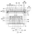
도 5는 본 발명의 다른 실시예에 따른 플라즈마 처리 장치를 나타낸 단면도이다.
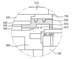
도 6은 도 5의 VI 부위를 확대해서 나타낸 단면도이다.
도 7은 도 5에 도시된 플라즈마 처리 장치의 냉각 유닛을 나타낸 블럭도이다.1 is a cross-sectional view showing a plasma processing device according to an embodiment of the present invention.
Figure 2 is an enlarged cross-sectional view of portion II of Figure 1.
FIG. 3 is a cross-sectional view showing a heating unit disposed within the liner shown in FIG. 2.
FIG. 4 is a block diagram showing a cooling unit of the plasma processing apparatus shown in FIG. 1.
Figure 5 is a cross-sectional view showing a plasma processing device according to another embodiment of the present invention.
Figure 6 is an enlarged cross-sectional view showing portion VI of Figure 5.
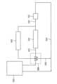
FIG. 7 is a block diagram showing a cooling unit of the plasma processing device shown in FIG. 5.
이하, 첨부한 도면들을 참조하여 본 발명의 바람직한 실시예들을 상세히 설명한다.Hereinafter, preferred embodiments of the present invention will be described in detail with reference to the attached drawings.
도 1은 본 발명의 일 실시예에 따른 플라즈마 처리 장치를 나타낸 단면도이고, 도 2는 도 1의 II 부위를 확대해서 나타낸 단면도이며, 도 3은 도 2에 도시된 라이너 내에 배치된 가열 유닛을 나타낸 단면도이고, 도 4는 도 1에 도시된 플라즈마 처리 장치의 냉각 유닛을 나타낸 블럭도이다.FIG. 1 is a cross-sectional view showing a plasma processing device according to an embodiment of the present invention, FIG. 2 is an enlarged cross-sectional view showing portion II of FIG. 1, and FIG. 3 shows a heating unit disposed in the liner shown in FIG. 2. It is a cross-sectional view, and FIG. 4 is a block diagram showing the cooling unit of the plasma processing device shown in FIG. 1.
도 1 내지 도 4를 참조하면, 플라즈마 처리 장치는 플라즈마 챔버(100), 기판 지지 유닛(200), 공정 가스 공급 유닛(300), 상부 전극 조립체(500), 라이너(600), 리드(700), 제 1 온도 조절기(800) 및 제 2 온도 조절기(900)를 포함할 수 있다.1 to 4, the plasma processing apparatus includes a
플라즈마 챔버(100)는 기판을 수용할 수 있다. 기판(W)은 반도체 기판, 유리 기판 등을 포함할 수 있다. 플라즈마 챔버(100)는 원통 형상을 가질 수 있다. 그러나, 플라즈마 챔버(100)는 직육면체 형상과 같은 다른 형상들을 가질 수도 있다.The
플라즈마 챔버(100)는 셔터(110)를 포함할 수 있다. 셔터(110)는 플라즈마 챔버(110)의 측벽에 형성될 수 있다. 기판은 셔터(110)를 통해서 플라즈마 챔버(110) 내로 반입되거나 플라즈마 챔버(110)로부터 반출될 수 있다. 플라즈마 챔버(100)는 금속 물질을 포함할 수 있으나, 이에 제한되지 않을 수 있다.The
라이너(600)는 플라즈마 챔버(100)의 내벽에 배치될 수 있다. 라이너(600)는 플라즈마의 파워, 구체적으로 플라즈마의 RF 파워에 의해 플라즈마 챔버(100)의 내벽이 손상되는 것을 억제시킬 수 있다. 라이너(600)는 플라즈마 챔버(100)의 내벽에 맞대어질 수 있다.The
라이너(600)는 플랜지(610)를 포함할 수 있다. 플랜지(610)는 라이너(600)의 상단 가장자리에 일체로 형성될 수 있다. 플랜지(610)는 플라즈마 챔버(100)의 측벽 상단과 결합되는 하부면을 가질 수 있다.Liner 600 may include
리드(700)는 플라즈마 챔버(100)와 라이너(600)를 덮을 수 있다. 구체적으로, 리드(700)는 플라즈마 챔버(100)의 측벽 상단과 라이너(600)의 플랜지(610) 상부면에 맞대어질 수 있다. 즉, 라이너(600)의 플랜지(610)는 플라즈마 챔버(100)의 측벽 상단과 리드(700) 사이에 개재될 수 있다.The
배기구(150)가 플라즈마 챔버(100)의 저면에 형성될 수 있다. 배기구(150)는 배기 라인을 통해 배기 펌프(152)에 연결될 수 있다. 배기 펌프(152)는 배기 라인을 통해 배기구(150)로 진공을 제공할 수 있다. 기판 처리 공정 중에 발생할 수 있는 부산물 및 플라즈마 챔버(100) 내에 머무르는 플라즈마는 배기 펌프(152)로부터 제공된 진공에 의해서 플라즈마 챔버(100)의 외부로 배출될 수 있다.An
기판 지지 유닛(200)은 플라즈마 챔버(100)의 저면에 배치될 수 있다. 기판 지지 유닛(200)은 기판을 지지할 수 있다. 기판 지지 유닛(200)은 정전기력을 이용하여 기판을 지지하는 정전척을 포함할 수 있다. 다른 실시예로서, 기판 지지 유닛(200)은 기계적 클램핑과 같은 다양한 방식으로 기판(W)을 지지하는 구조를 가질 수도 있다.The
기판 지지 유닛(200)이 정전척인 경우, 기판 지지 유닛(200)은 유전층(210), 포커스 링(250) 및 베이스(230)를 포함할 수 있다. 기판은 유전층(210)의 상부면에 배치될 수 있다. 따라서, 유전층(210)의 상부면은 기판의 하부면과 접촉할 수 있다. 유전층(210)은 원판 형상을 가질 수 있다. 유전층(210)은 기판보다 작은 반경을 가질 수 있다. 유전층(210)은 세라믹 물질을 포함할 수 있다.When the
하부 전극(212)이 유전층(210)의 내부에 배치될 수 있다. 전원(240)이 하부 전극(212)에 연결될 수 있다. 하부 전극(212)은 전원(240)으로부터 기판이 유전층(210)에 흡착될 수 있도록 정전기력을 제공받을 수 있다. 하부 전극(212)은 모노 폴라 전극을 포함할 수 있다.The
기판을 가열하는 히터(214)가 유전층(210) 내에 배치될 수 있다. 히터(214)는 하부 전극(212)의 하부에 배치될 수 있다. 히터(214)는 나선 형상의 코일을 포함할 수 있다.A
베이스(230)는 유전층(210)을 지지할 수 있다. 베이스(230)는 유전층(210)의 아래에 배치될 수 있다. 베이스(230)는 유전층(210)과 결합될 수 있다. 베이스(230)의 상부면은 중앙 부위가 가장자리 부위보다 돌출된 단차 구조를 가질 수 있다. 베이스(230)의 중앙 부위는 유전층(210)의 저면과 대응되는 면적을 가질 수 있다.
냉각 통로(232)가 베이스(230)의 내부에 형성될 수 있다. 냉각 유체가 냉각 통로(232)를 통해서 흐를 수 있다. 냉각 통로(232)는 나선 형상을 가질 수 있다.A
베이스(230)는 플라즈마 챔버(100)의 외부에 위치된 고주파 전원(242)에 연결될 수 있다. 고주파 전원(242)은 베이스(230)에 전력을 인가할 수 있다. 베이스(230)에 인가된 전력은 플라즈마 챔버(100) 내에 발생된 플라즈마가 베이스(230)을 향해 이동되도록 안내할 수 있다. 베이스(230)는 금속 재질을 포함할 수 있다.The base 230 may be connected to a high-
포커스 링(250)은 플라즈마를 기판으로 집중시킬 수 있다. 포커스 링(250)은 유전층(210)의 상부면 가장자리 부위에 배치될 수 있다. 포커스 링(250)은 기판을 둘러싸는 링 형상을 가질 수 있다. 포커스 링(250)은 실리콘 산화물(SiO2)을 포함할 수 있다. 다른 실시예로서, 포커스 링(250)은 실리콘 탄화물(SiC)과 같은 다른 물질들을 포함할 수도 있다.The
포커스 링(250)은 단일 링을 포함할 수 있다. 다른 실시예로서, 포커스 링(250)은 복수개의 링들을 포함할 수도 있다. 예를 들어서, 포커스 링(250)은 내측 링, 및 내측 링을 둘러싸는 외측 링을 포함할 수도 있다.
가스 공급 유닛(300)은 기판 지지 유닛(200)으로 지지된 기판 상으로 공정 가스를 공급할 수 있다. 가스 공급 유닛(300)은 가스 탱크(350) 및 가스 공급 라인(330)을 포함할 수 있다. 가스 탱크(350)는 공정 가스를 저장할 수 있다. 가스 공급 라인(330)은 플라즈마 챔버(100)에 연결될 수 있다.The gas supply unit 300 may supply process gas onto the substrate supported by the
상부 전극 조립체(500)는 플라즈마 챔버(100) 내의 상부 공간에 배치될 수 있다. 상부 전극 조립체(500)는 상부 전극(510), 분배판(520), 가스 분배판(530) 및 샤워 헤드(540)를 포함할 수 있다.The
분배판(520)은 상부 전극(510)의 하부면에 배치될 수 있다. 가스 분배판(530)은 분배판(520)의 하부면에 배치될 수 있다. 샤워 헤드(540)는 가스 분배판(530)의 하부면에 배치될 수 있다. 전원(400)이 상부 전극(510)에 연결되어, 상부 전극(510)에 RF 파워를 인가할 수 있다.The
가스 분배판(530)은 내열층(534)을 포함할 수 있다. 내열층(534)은 가스 분배판(530)의 하부면에 배치될 수 있다. 따라서, 내열층(534)은 샤워 헤드(540)의 상부면과 접촉할 수 있다. 내열층(534)은 테프론, PI 등과 같은 우수한 내열성을 갖는 폴리머를 포함할 수 있다.The
상부 전극(510)은 가스 통로(512)를 가질 수 있다. 가스 공급 라인(330)이 가스 통로(512)에 연결될 수 있다. 분배판(520)은 가스 통로(512)와 연통된 가스 분배 통로(522)를 가질 수 있다. 가스 분배판(530)은 가스 분배 통로(522)와 연통된 가스 분배홈(532)을 가질 수 있다. 샤워 헤드(540)는 가스 분배홈(532)와 연통되어 공정 가스를 플라즈마 챔버(100) 내로 분사하는 가스 분사공(542)들을 가질 수 있다.The
제 1 온도 조절기(800)는 상부 전극 조립체(500)의 온도를 조절할 수 있다. 제 1 온도 조절기(800)는 제 1 가열 유닛(810) 및 제 1 냉각 유닛(820)을 포함할 수 있다.The
제 1 가열 유닛(810)은 제 1 히터(812) 및 전원(814)을 포함할 수 있다. 제 1 히터(812)는 가스 분배판(530)에 내장될 수 있다. 전원(814)은 제 1 히터(812)로 파워를 제공할 수 있다.The
제 1 냉각 유닛(820)은 메인 냉각 통로(822)를 포함할 수 있다. 메인 냉각 통로(822)는 분배판(520) 내에 형성될 수 있다. 메인 냉각 통로(822)는 냉각제를 형성하는 칠러(830)에 연결될 수 있다.The
여기서, 플라즈마 처리 공정이 수행되면, 냉각제가 제 1 냉각 통로(822)로 공급되어 상부 전극 조립체(500)를 냉각시킬 수 있다. 반면에, 플라즈마 처리 공정이 완료된 이후 세정 공정 중에는, 냉각제는 제 1 냉각 통로(822)로 공급되지 않을 수 있다.Here, when the plasma treatment process is performed, coolant may be supplied to the
세정 공정 완료 이후 플라즈마 처리 공정이 시작되면, RF 파워가 설정된 파워에 도달하지 않았음에도 불구하고 낮은 온도의 냉각제가 메인 냉각 통로(822)로 공급될 수 있다. 이로 인하여, 상부 전극 조립체(500)의 온도가 설정된 공정 온도보다 낮은 상태에서 플라즈마 처리 공정이 수행될 수 있다.When the plasma treatment process starts after the cleaning process is completed, low-temperature coolant may be supplied to the
또한, 플라즈마 챔버(100) 내에서 발생된 플라즈마의 높은 온도에 의해서 제 1 히터(812)가 정지될 수 있다. 이로 인하여, 플라즈마 챔버(100)의 내벽 및 라이너(600)의 온도를 제어할 수가 없게 될 수 있다. 즉, 플라즈마 챔버(100)의 내부 온도가 설정된 공정 온도로부터 크게 벗어날 수 있다.Additionally, the
제 2 온도 조절기(900)는 플라즈마의 파워에 따라 라이너(600)의 온도를 조절할 수 있다. 제 2 온도 조절기(900)는 제 2 가열 유닛(910) 및 제 2 냉각 유닛(920)을 포함할 수 있다.The
제 2 가열 유닛(910)은 제 2 히터(912)를 포함할 수 있다. 제 2 히터(912)는 라이너(600)를 가열할 수 있다. 특히, 제 2 히터(912)는 라이너(600)의 플랜지(610) 내에 배치될 수 있다. 다른 실시예로서, 라이너(600)가 제 2 히터(912)를 수용할 정도의 두께를 갖는다면, 제 2 히터(912)는 라이너(600) 내에 배치될 수도 있다.The
제 2 히터(912)는 제 1 히팅 코일(914) 및 제 2 히팅 코일(916)을 포함할 수 있다. 제 1 전원(915)이 제 1 히팅 코일(914)로 파워를 인가할 수 있다. 제 2 전원(917)이 제 2 히팅 코일(916)로 파워를 인가할 수 있다. 즉, 제 1 히팅 코일(914)과 제 2 히팅 코일(916)은 독립적으로 작동될 수 있다.The
라이너(600)는 제 1 부위와 제 2 부위로 구분될 수 있다. 제 1 부위는 기판이 출입하는 셔터(110)와 인접할 수 있다. 반면에, 제 2 부위는 셔터(110)로부터 멀리 이격될 수 있다. 라이너(600)의 제 1 부위는 셔터(110)와 인접하므로, 라이너(600)의 제 1 부위에서의 온도 변동은 제 2 부위의 온도 변동에 비해서 상대적으로 클 수 있다.The
제 1 히팅 코일(914)은 라이너(600)의 제 1 부위, 즉 플랜지(610)의 제 1 부위 내에 배치되어, 제 1 부위를 가열할 수 있다. 제 2 히팅 코일(916)은 라이너(600)의 제 2 부위, 즉 플랜지(610)의 제 2 부위 내에 배치되어, 제 2 부위를 가열할 수 있다.The
본 실시예에서, 라이너(600)의 제 1 부위는 라이너(600)의 절반에 해당되고, 라이너(600)의 제 2 부위는 제 1 부위를 제외한 라이너(600)의 나머지 절반에 해당될 수 있다. 이에 따라, 제 1 히팅 코일(914)과 제 2 히팅 코일(916)은 실질적으로 동일한 대략 반원 형상을 가질 수 있다. 그러나, 라이너(600)의 제 1 부위와 제 2 부위를 구분하는 기준은 셔터(110)의 위치, 크기, 동작 주기 등에 따라 변경될 수 있다. 그러므로, 제 1 히팅 코일(914)과 제 2 히팅 코일(916)의 형상들은 제 1 부위와 제 2 부위를 구분하는 기준에 따라 변경될 수 있다. 또한, 라이너(600)는 3개 이상의 부위들로 구분될 수도 있다. 이러한 경우, 히팅 코일의 수도 라이너(600)의 구분된 부위들의 수와 대응할 수 있다.In this embodiment, the first portion of the
제 2 냉각 유닛(920)은 플라즈마의 파워에 따라 라이너(600)를 선택적으로 냉각시킬 수 있다. 제 2 냉각 유닛(920)은 냉각 통로(922) 및 복귀 통로(924)를 포함할 수 있다.The
냉각 통로(922)는 리드(700) 내에 형성될 수 있다. 냉각 통로(922)는 분배판(520) 내에 형성된 메인 냉각 통로(822)에 연결될 수 있다. 따라서, 칠러(830)에서 형성된 냉각제는 메인 냉각 통로(860)를 경유해서 냉각 통로(922)로 제공되어, 리드(700) 및 라이너(600)를 냉각시킬 수 있다. 즉, 라이너(600)는 리드(700)의 냉각에 의해 간접적으로 냉각될 수 있다. 다른 실시예로서, 냉각 통로(922)는 별도의 칠러에 연결될 수도 있다.
복귀 통로(924)는 냉각 통로(922)와 칠러(830) 사이에 연결될 수 있다. 리드(700)를 냉각시킨 냉각제는 복귀 통로(924)를 통해서 칠러(830)로 복귀될 수 있다.The
바이패스 통로(926)가 메인 냉각 통로(822)와 복귀 통로(924) 사이에 연결될 수 있다. 따라서, 메인 냉각 통로(822)를 통해 흐르던 냉각제 전부 또는 일부가 바이패스 통로(926)를 경유해서 칠러(830)로 복귀될 수 있다.A
삼방 밸브(930)가 메인 냉각 통로(822)에 배치될 수 있다. 삼방 밸브(930)는 플라즈마의 파워에 따라 메인 냉각 통로(822) 및 바이패스 통로(926)로 흐르는 냉각제의 유량들을 선택적으로 제어할 수 있다.A three-
제어부(840)는 플라즈마의 파워, 즉 상부 전극 조립체(500)에 인가된 RF 파워를 감지할 수 있다. 제어부(840)는 감지된 플라즈마의 파워에 따라 삼방 밸브(930)의 개도각을 조절할 수 있다.The
예를 들어서, 플라즈마의 파워가 설정된 파워에 도달하지 않은 상태라면, 상부 전극 조립체(500)와 리드(700) 및 라이너(600)를 냉각시킬 필요가 없을 것이다. 따라서, 제어부(840)는 상부 전극 조립체(500)를 향하는 삼방 밸브(930)의 개방각을 줄이거나 또는 완전히 차단하고 바이패스 통로(926)로 이어진 삼방 밸브(930)의 개방각을 증가시켜서, 상부 전극 조립체(500)로 공급되는 냉각제의 유량을 감소시킬 수 있다. 이러한 경우, 대부분의 냉각제는 바이패스 통로(926)를 통해서 칠러(830)로 복귀할 것이다.For example, if the power of the plasma has not reached the set power, there will be no need to cool the
반면에, 플라즈마의 파워가 설정된 파워에 도달하면, 제어부(840)는 바이패스 통로(926)를 향하는 삼방 밸브(930)의 개방각을 줄이거나 또는 완전히 차단하고 상부 전극 조립체(500)로 향하는 삼방 밸브(930)의 개방각을 증가시켜서, 상부 전극 조립체(500)로 공급되는 냉각제의 유량을 증가시킬 수 있다. 이러한 경우, 대부분의 냉각제는 메인 냉각 통로(822) 및 냉각 통로(922)를 통해서 상부 전극 조립체(500)와 리드(700)로 공급될 수가 있다.On the other hand, when the power of the plasma reaches the set power, the
도 5는 본 발명의 다른 실시예에 따른 플라즈마 처리 장치를 나타낸 단면도이고, 도 6은 도 5의 VI 부위를 확대해서 나타낸 단면도이며, 도 7은 도 5에 도시된 플라즈마 처리 장치의 냉각 유닛을 나타낸 블럭도이다.FIG. 5 is a cross-sectional view showing a plasma processing device according to another embodiment of the present invention, FIG. 6 is an enlarged cross-sectional view showing portion VI of FIG. 5, and FIG. 7 is a cooling unit of the plasma processing device shown in FIG. 5. It is a block diagram.
본 실시예에 따른 플라즈마 처리 장치는 제 2 온도 조절기의 제 2 냉각 유닛을 제외하고는 도 1에 도시된 플라즈마 처리 장치의 구성요소들과 실질적으로 동일한 구성요소들을 포함할 수 있다. 따라서, 동일한 구성요소들은 동일한 참조부호들로 나타내고, 또한 동일한 구성요소들에 대한 반복 설명은 생략할 수 있다.The plasma processing apparatus according to this embodiment may include substantially the same components as those of the plasma processing apparatus shown in FIG. 1 except for the second cooling unit of the second temperature controller. Accordingly, the same components are indicated by the same reference numerals, and repeated descriptions of the same components can be omitted.
도 5 내지 도 7을 참조하면, 제 2 냉각 유닛(920a)의 냉각 통로(922a)는 라이너(600) 내에 형성될 수 있다. 특히, 냉각 통로(922a)는 라이너(600)의 플랜지(610) 내에 형성될 수 있다.Referring to FIGS. 5 to 7 , the
냉각 통로(922a)는 분배판(520) 내에 형성된 메인 냉각 통로(822)에 연결될 수 있다. 따라서, 칠러(830)에서 형성된 냉각제는 메인 냉각 통로(860)를 경유해서 냉각 통로(922)로 제공되어, 리드(700) 및 라이너(600)를 냉각시킬 수 있다. 즉, 라이너(600)는 라이너(600) 내에 형성된 냉각 통로(922a)로 제공된 냉각제에 의해 직접적으로 냉각될 수 있다. 다른 실시예로서, 냉각 통로(922a)는 별도의 칠러에 연결될 수도 있다.The
상기된 본 실시예들에 따르면, 플라즈마의 파워에 따라 라이너의 온도가 조절되므로, 상부 전극의 온도를 공정 온도로 정밀하게 제어할 수 있게 되어, 플라즈마의 내부 온도를 설정된 공정 온도에 부합되도록 일정하게 유지시킬 수 있다. 따라서, 플라즈마 처리 공정이 설정된 조건에 따라 정확하게 수행될 수가 있다.According to the above-described embodiments, the temperature of the liner is adjusted according to the power of the plasma, so that the temperature of the upper electrode can be precisely controlled to the process temperature, and the internal temperature of the plasma is kept constant to match the set process temperature. It can be maintained. Therefore, the plasma treatment process can be accurately performed according to set conditions.
상술한 바와 같이, 본 발명의 바람직한 실시예들을 참조하여 설명하였지만 해당 기술 분야의 숙련된 당업자라면 하기의 특허 청구의 범위에 기재된 본 발명의 사상 및 영역으로부터 벗어나지 않는 범위 내에서 본 발명을 다양하게 수정 및 변경시킬 수 있음을 이해할 수 있을 것이다.As described above, the present invention has been described with reference to preferred embodiments, but those skilled in the art may modify the present invention in various ways without departing from the spirit and scope of the present invention as set forth in the claims below. and that it can be changed.
100 ; 플라즈마 챔버110 ; 셔터
150 ; 배기구152 ; 배기 펌프
200 ; 기판 지지 유닛210 ; 유전층
212 ; 하부 전극214 ; 히터
230 ; 베이스232 ; 냉각 통로
240 ; 전원242 ; 전원
250 ; 포커스 링300 ; 가스 공급 유닛
330 ; 가스 공급 라인350 ; 가스 탱크
400 ; 전원500 ; 상부 전극 조립체
510 ; 상부 전극512 ; 가스 통로
520 ; 분배판522 ; 가스 분배 통로
530 ; 가스 분배판532 ; 가스 분배홈
540 ; 샤워 헤드542 ; 가스 분사공
600 ; 라이너610 ; 플랜지
700 ; 리드800 ; 제 1 온도 조절기
810 ; 제 1 가열 유닛812 ; 제 1 히터
814 ; 전원820 ; 제 1 냉각 유닛
822 ; 메인 냉각 통로830 ; 칠러
840 ; 제어부850 ; 삼방 밸브
900 ; 제 2 온도 조절기912 ; 제 2 히터
914 ; 제 1 히팅 코일915 ; 제 1 전원
916 ; 제 2 히팅 코일917 ; 제 2 전원
920 ; 제 2 냉각 유닛922 ; 냉각 통로
924 ; 복귀 통로926 ; 바이패스 통로
930 ; 삼방 밸브100 ;
150 ;
200 ;
212 ;
230 ;
240 ;
250 ; focus ring 300 ; gas supply unit
330 ;
400 ;
510 ;
520 ;
530 ;
540 ;
600 ;
700 ; lead 800 ; first thermostat
810 ;
814 ;
822 ;
840 ; Control unit 850; three way valve
900 ;
914 ; First heating coil 915; 1st power source
916 ;
920 ;
924 ; return
930 ; three way valve
Claims (10)
Translated fromKorean상기 플라즈마의 파워에 따라 상기 라이너를 선택적으로 냉각하여, 상기 플라즈마 챔버 내에 배치된 상부 전극의 온도를 조절하는 냉각 유닛을 포함하고,
상기 가열 유닛은 상기 라이너의 상단 가장자리로부터 연장되어 상기 플라즈마 챔버의 내벽 상단과 상기 라이너를 덮는 리드(lid) 사이에 개재된 플랜지(flange)를 가열하며,
상기 가열 유닛은
상기 플라즈마 챔버로 기판이 출입하는 셔터(shutter)와 인접한 상기 플랜지의 제 1 부위 내에 배치된 제 1 히터; 및
상기 제 1 부위를 제외한 상기 플랜지의 나머지 제 2 부위 내에 배치된 제 2 히터를 포함하고,
상기 냉각 유닛은
냉각제를 형성하기 위한 칠러(chiller);
상기 라이너 내에 형성되고, 상기 칠러에 연결된 냉각 통로;
상기 냉각 통로와 상기 칠러를 연결하는 복귀 통로;
상기 냉각 통로와 상기 복귀 통로를 연결하는 바이패스 통로;
상기 플라즈마의 파워에 따라 상기 냉각 통로와 상기 바이패스 통로로 제공되는 상기 냉각제의 유량들을 선택적으로 조절하기 위한 삼방 밸브; 및
플라즈마 처리 장치의 상부 전극 내에 형성되어 상기 칠러와 상기 냉각 통로 사이를 연결하는 메인 냉각 통로를 포함하며,
상기 삼방 밸브는 상기 메인 냉각 통로에 배치된 플라즈마 처리 장치의 온도 조절기.a heating unit for heating a liner disposed on the inner wall of the plasma chamber defining a space in which plasma is formed; and
A cooling unit that selectively cools the liner according to the power of the plasma and adjusts the temperature of the upper electrode disposed in the plasma chamber,
The heating unit extends from the top edge of the liner to heat a flange sandwiched between the top of the inner wall of the plasma chamber and a lid covering the liner,
The heating unit is
a first heater disposed in a first portion of the flange adjacent to a shutter through which a substrate enters and exits the plasma chamber; and
A second heater disposed in the remaining second portion of the flange excluding the first portion,
The cooling unit is
Chiller for forming coolant;
a cooling passage formed within the liner and connected to the chiller;
a return passage connecting the cooling passage and the chiller;
a bypass passage connecting the cooling passage and the return passage;
a three-way valve for selectively adjusting flow rates of the coolant provided to the cooling passage and the bypass passage according to the power of the plasma; and
It includes a main cooling passage formed within the upper electrode of the plasma processing device and connecting the chiller and the cooling passage,
The three-way valve is a temperature controller of a plasma processing device disposed in the main cooling passage.
상기 플라즈마 챔버의 공간 중 하부에 배치되어, 상기 플라즈마에 의해 처리될 기판을 지지하는 기판 지지 유닛;
상기 플라즈마의 측벽에 형성되어, 상기 기판이 출입하는 셔터;
상기 플라즈마 챔버 내의 공간 중 상부에 배치된 상부 전극 조립체;
상기 플라즈마 챔버의 내벽에 배치된 라이너;
상기 라이너를 덮는 리드;
상기 상부 전극 조립체의 온도를 조절하기 위한 제 1 온도 조절기; 및
상기 플라즈마의 파워에 따라 상기 라이너의 온도를 조절하여, 상기 상부 전극 조립체의 온도를 제어하는 제 2 온도 조절기를 포함하고,
상기 제 2 온도 조절기는
상기 라이너 내에 배치된 가열 유닛; 및
상기 플라즈마의 파워에 따라 상기 라이너를 선택적으로 냉각하기 위한 냉각 유닛을 포함하며,
상기 가열 유닛은
상기 셔터와 인접한 상기 라이너의 제 1 부위 내에 배치된 제 1 히터; 및
상기 제 1 부위를 제외한 상기 라이너의 나머지 제 2 부위 내에 배치된 제 2 히터를 포함하고,
상기 냉각 유닛은
냉각제를 형성하기 위한 칠러(chiller);
상기 상부 전극 조립체 내에 형성되고, 상기 칠러와 연결된 메인 냉각 통로;
상기 라이너 내에 형성되고, 상기 메인 냉각 통로와 연결된 냉각 통로;
상기 냉각 통로와 상기 칠러를 연결하는 복귀 통로;
상기 메인 냉각 통로와 상기 복귀 통로를 연결하는 바이패스 통로;
상기 플라즈마의 파워에 따라 상기 메인 냉각 통로와 상기 바이패스 통로로 제공되는 상기 냉각제의 유량들을 선택적으로 조절하기 위한 삼방 밸브; 및
상기 플라즈마의 파워를 감지하고, 상기 감지된 플라즈마의 파워에 따라 상기 삼방 밸브의 개도각을 조절하는 조절부를 포함하고,
상기 삼방 밸브는 상기 메인 냉각 통로에 배치된 플라즈마 처리 장치.
A plasma chamber defining a space in which plasma is formed;
a substrate support unit disposed in a lower part of the space of the plasma chamber to support a substrate to be processed by the plasma;
A shutter formed on a side wall of the plasma through which the substrate enters and exits;
an upper electrode assembly disposed at the upper part of the space within the plasma chamber;
A liner disposed on the inner wall of the plasma chamber;
a lid covering the liner;
a first temperature controller for controlling the temperature of the upper electrode assembly; and
A second temperature controller that controls the temperature of the upper electrode assembly by adjusting the temperature of the liner according to the power of the plasma,
The second temperature controller is
a heating unit disposed within the liner; and
It includes a cooling unit for selectively cooling the liner according to the power of the plasma,
The heating unit is
a first heater disposed within a first portion of the liner adjacent the shutter; and
A second heater disposed in the remaining second portion of the liner excluding the first portion,
The cooling unit is
Chiller for forming coolant;
a main cooling passage formed within the upper electrode assembly and connected to the chiller;
a cooling passage formed within the liner and connected to the main cooling passage;
a return passage connecting the cooling passage and the chiller;
a bypass passage connecting the main cooling passage and the return passage;
a three-way valve for selectively adjusting flow rates of the coolant provided to the main cooling passage and the bypass passage according to the power of the plasma; and
A control unit that detects the power of the plasma and adjusts the opening angle of the three-way valve according to the detected power of the plasma,
The three-way valve is a plasma processing device disposed in the main cooling passage.
Priority Applications (2)
| Application Number | Priority Date | Filing Date | Title |
|---|---|---|---|
| KR1020160175643AKR102587615B1 (en) | 2016-12-21 | 2016-12-21 | Temperature controller of a plasma-processing apparatus and plasma-processing apparatus including the same |
| US15/652,345US10804120B2 (en) | 2016-12-21 | 2017-07-18 | Temperature controller and a plasma-processing apparatus including the same |
Applications Claiming Priority (1)
| Application Number | Priority Date | Filing Date | Title |
|---|---|---|---|
| KR1020160175643AKR102587615B1 (en) | 2016-12-21 | 2016-12-21 | Temperature controller of a plasma-processing apparatus and plasma-processing apparatus including the same |
Publications (2)
| Publication Number | Publication Date |
|---|---|
| KR20180072258A KR20180072258A (en) | 2018-06-29 |
| KR102587615B1true KR102587615B1 (en) | 2023-10-11 |
Family
ID=62561932
Family Applications (1)
| Application Number | Title | Priority Date | Filing Date |
|---|---|---|---|
| KR1020160175643AActiveKR102587615B1 (en) | 2016-12-21 | 2016-12-21 | Temperature controller of a plasma-processing apparatus and plasma-processing apparatus including the same |
Country Status (2)
| Country | Link |
|---|---|
| US (1) | US10804120B2 (en) |
| KR (1) | KR102587615B1 (en) |
Families Citing this family (10)
| Publication number | Priority date | Publication date | Assignee | Title |
|---|---|---|---|---|
| KR102516778B1 (en)* | 2018-02-08 | 2023-04-03 | 주성엔지니어링(주) | Apparatus and method for cleaning chamber |
| JP7240958B2 (en)* | 2018-09-06 | 2023-03-16 | 東京エレクトロン株式会社 | Plasma processing equipment |
| JP7112915B2 (en)* | 2018-09-07 | 2022-08-04 | 東京エレクトロン株式会社 | temperature control system |
| KR102529845B1 (en)* | 2018-09-26 | 2023-05-08 | 어플라이드 머티어리얼스, 인코포레이티드 | Thermally Conductive Spacers for Plasma Processing Chambers |
| US11532461B2 (en)* | 2018-10-23 | 2022-12-20 | Tokyo Electron Limited | Substrate processing apparatus |
| JP7278172B2 (en)* | 2018-10-23 | 2023-05-19 | 東京エレクトロン株式会社 | Substrate processing equipment |
| CN208835019U (en)* | 2018-11-12 | 2019-05-07 | 江苏鲁汶仪器有限公司 | Reaction chamber inner lining |
| US12266588B2 (en) | 2019-07-16 | 2025-04-01 | Lam Research Corporation | Thermoelectric cooling pedestal for substrate processing systems |
| CN112951694B (en)* | 2019-11-26 | 2024-05-10 | 中微半导体设备(上海)股份有限公司 | Plasma processing apparatus and method for processing semiconductor wafer |
| US12232299B2 (en)* | 2022-10-12 | 2025-02-18 | Applied Materials, Inc. | Methods and apparatus for cooling a substrate support |
Citations (4)
| Publication number | Priority date | Publication date | Assignee | Title |
|---|---|---|---|---|
| US20050241766A1 (en)* | 2004-04-30 | 2005-11-03 | Rajinder Dhindsa | Apparatus including gas distribution member supplying process gas and radio frequency (RF) power for plasma processing |
| US20070240979A1 (en)* | 2004-10-13 | 2007-10-18 | Tokyo Electron Limited | Shield Body and Vacuum Processing Apparatus |
| US20080178797A1 (en)* | 2007-01-30 | 2008-07-31 | Fodor Mark A | Processing chamber with heated chamber liner |
| US20130087286A1 (en)* | 2011-10-05 | 2013-04-11 | Applied Materials, Inc. | Symmetric plasma process chamber |
Family Cites Families (13)
| Publication number | Priority date | Publication date | Assignee | Title |
|---|---|---|---|---|
| JPH0529225A (en) | 1991-07-22 | 1993-02-05 | Toshiba Corp | Vapor phase growth equipment |
| US20050230350A1 (en)* | 2004-02-26 | 2005-10-20 | Applied Materials, Inc. | In-situ dry clean chamber for front end of line fabrication |
| JP2006066292A (en) | 2004-08-27 | 2006-03-09 | Sekisui Chem Co Ltd | Structure and electrode replacing method for plasma surface treating device |
| JP4838197B2 (en)* | 2007-06-05 | 2011-12-14 | 東京エレクトロン株式会社 | Plasma processing apparatus, electrode temperature adjusting apparatus, electrode temperature adjusting method |
| JP5475261B2 (en) | 2008-03-31 | 2014-04-16 | 東京エレクトロン株式会社 | Plasma processing equipment |
| US20110061810A1 (en)* | 2009-09-11 | 2011-03-17 | Applied Materials, Inc. | Apparatus and Methods for Cyclical Oxidation and Etching |
| JP2011187758A (en)* | 2010-03-10 | 2011-09-22 | Tokyo Electron Ltd | Temperature control system, temperature control method, plasma treatment device, and computer storage medium |
| US8597462B2 (en) | 2010-05-21 | 2013-12-03 | Lam Research Corporation | Movable chamber liner plasma confinement screen combination for plasma processing apparatuses |
| JP5709505B2 (en)* | 2010-12-15 | 2015-04-30 | 東京エレクトロン株式会社 | Plasma processing apparatus, plasma processing method, and storage medium |
| US20130105085A1 (en)* | 2011-10-28 | 2013-05-02 | Applied Materials, Inc. | Plasma reactor with chamber wall temperature control |
| US9295181B2 (en) | 2012-11-08 | 2016-03-22 | International Business Machines Corporation | Coolant-conditioning unit with automated control of coolant flow valves |
| US9677176B2 (en)* | 2013-07-03 | 2017-06-13 | Novellus Systems, Inc. | Multi-plenum, dual-temperature showerhead |
| US10519545B2 (en)* | 2016-05-31 | 2019-12-31 | Taiwan Semiconductor Manufacturing Co., Ltd. | Systems and methods for a plasma enhanced deposition of material on a semiconductor substrate |
- 2016
- 2016-12-21KRKR1020160175643Apatent/KR102587615B1/enactiveActive
- 2017
- 2017-07-18USUS15/652,345patent/US10804120B2/enactiveActive
Patent Citations (4)
| Publication number | Priority date | Publication date | Assignee | Title |
|---|---|---|---|---|
| US20050241766A1 (en)* | 2004-04-30 | 2005-11-03 | Rajinder Dhindsa | Apparatus including gas distribution member supplying process gas and radio frequency (RF) power for plasma processing |
| US20070240979A1 (en)* | 2004-10-13 | 2007-10-18 | Tokyo Electron Limited | Shield Body and Vacuum Processing Apparatus |
| US20080178797A1 (en)* | 2007-01-30 | 2008-07-31 | Fodor Mark A | Processing chamber with heated chamber liner |
| US20130087286A1 (en)* | 2011-10-05 | 2013-04-11 | Applied Materials, Inc. | Symmetric plasma process chamber |
Also Published As
| Publication number | Publication date |
|---|---|
| KR20180072258A (en) | 2018-06-29 |
| US10804120B2 (en) | 2020-10-13 |
| US20180174869A1 (en) | 2018-06-21 |
Similar Documents
| Publication | Publication Date | Title |
|---|---|---|
| KR102587615B1 (en) | Temperature controller of a plasma-processing apparatus and plasma-processing apparatus including the same | |
| US11062885B2 (en) | Supporting unit and substrate treating apparatus including the same | |
| US9410753B2 (en) | Substrate temperature adjusting method and a method of changing the temperature control range of a heater in a substrate processing apparatus | |
| US20210233799A1 (en) | Lift pin assembly | |
| KR102466150B1 (en) | Heat treatment apparatus and heat treatment method | |
| TWI674646B (en) | Dual-zone heater for plasma processing | |
| JP6268095B2 (en) | Thermal management of edge rings in semiconductor processing. | |
| CN106469666A (en) | Susceptor and substrate processing equipment | |
| TW201518538A (en) | Pixelated cooling, temperature controlled substrate support assembly | |
| TWI837376B (en) | Substrate processing apparatus | |
| CN1841654A (en) | Temperature control device, method and program for mounting table, and processing device | |
| TWI878496B (en) | Substrate support | |
| US20190326139A1 (en) | Ceramic wafer heater having cooling channels with minimum fluid drag | |
| TW202224504A (en) | Plasma processing apparatus | |
| KR101909190B1 (en) | Apparatus for controlling temperature of substrate, and apparatus for treating substrate comprising the same | |
| CN105590880A (en) | Reaction cavity | |
| KR101955575B1 (en) | Apparatus and Method for treating substrate | |
| KR101966800B1 (en) | Apparatus and Method for treating substrate | |
| TWI874429B (en) | Placing table and substrate processing apparatus | |
| CN113921451A (en) | Mounting table, apparatus for processing substrate and method for temperature adjustment of substrate | |
| KR102186071B1 (en) | Apparatus and method for treating substrate | |
| KR101581317B1 (en) | Apparatus and Method for treating substrate | |
| KR20240094746A (en) | Apparatus for processing substrate | |
| KR20250078382A (en) | Substrate processing apparatus |
Legal Events
| Date | Code | Title | Description |
|---|---|---|---|
| PA0109 | Patent application | Patent event code:PA01091R01D Comment text:Patent Application Patent event date:20161221 | |
| PG1501 | Laying open of application | ||
| A201 | Request for examination | ||
| PA0201 | Request for examination | Patent event code:PA02012R01D Patent event date:20210615 Comment text:Request for Examination of Application Patent event code:PA02011R01I Patent event date:20161221 Comment text:Patent Application | |
| E902 | Notification of reason for refusal | ||
| PE0902 | Notice of grounds for rejection | Comment text:Notification of reason for refusal Patent event date:20230518 Patent event code:PE09021S01D | |
| E701 | Decision to grant or registration of patent right | ||
| PE0701 | Decision of registration | Patent event code:PE07011S01D Comment text:Decision to Grant Registration Patent event date:20230922 | |
| GRNT | Written decision to grant | ||
| PR0701 | Registration of establishment | Comment text:Registration of Establishment Patent event date:20231005 Patent event code:PR07011E01D | |
| PR1002 | Payment of registration fee | Payment date:20231006 End annual number:3 Start annual number:1 | |
| PG1601 | Publication of registration |