KR102586986B1 - Film forming method using epitaxial growth and epitaxial growth apparatus - Google Patents
Film forming method using epitaxial growth and epitaxial growth apparatusDownload PDFInfo
- Publication number
- KR102586986B1 KR102586986B1KR1020227015006AKR20227015006AKR102586986B1KR 102586986 B1KR102586986 B1KR 102586986B1KR 1020227015006 AKR1020227015006 AKR 1020227015006AKR 20227015006 AKR20227015006 AKR 20227015006AKR 102586986 B1KR102586986 B1KR 102586986B1
- Authority
- KR
- South Korea
- Prior art keywords
- ceiling
- ring
- substrate
- ceiling plate
- delete delete
- Prior art date
- Legal status (The legal status is an assumption and is not a legal conclusion. Google has not performed a legal analysis and makes no representation as to the accuracy of the status listed.)
- Active
Links
Images

Classifications
- C—CHEMISTRY; METALLURGY
- C30—CRYSTAL GROWTH
- C30B—SINGLE-CRYSTAL GROWTH; UNIDIRECTIONAL SOLIDIFICATION OF EUTECTIC MATERIAL OR UNIDIRECTIONAL DEMIXING OF EUTECTOID MATERIAL; REFINING BY ZONE-MELTING OF MATERIAL; PRODUCTION OF A HOMOGENEOUS POLYCRYSTALLINE MATERIAL WITH DEFINED STRUCTURE; SINGLE CRYSTALS OR HOMOGENEOUS POLYCRYSTALLINE MATERIAL WITH DEFINED STRUCTURE; AFTER-TREATMENT OF SINGLE CRYSTALS OR A HOMOGENEOUS POLYCRYSTALLINE MATERIAL WITH DEFINED STRUCTURE; APPARATUS THEREFOR
- C30B25/00—Single-crystal growth by chemical reaction of reactive gases, e.g. chemical vapour-deposition growth
- C30B25/02—Epitaxial-layer growth
- C30B25/08—Reaction chambers; Selection of materials therefor
- C—CHEMISTRY; METALLURGY
- C30—CRYSTAL GROWTH
- C30B—SINGLE-CRYSTAL GROWTH; UNIDIRECTIONAL SOLIDIFICATION OF EUTECTIC MATERIAL OR UNIDIRECTIONAL DEMIXING OF EUTECTOID MATERIAL; REFINING BY ZONE-MELTING OF MATERIAL; PRODUCTION OF A HOMOGENEOUS POLYCRYSTALLINE MATERIAL WITH DEFINED STRUCTURE; SINGLE CRYSTALS OR HOMOGENEOUS POLYCRYSTALLINE MATERIAL WITH DEFINED STRUCTURE; AFTER-TREATMENT OF SINGLE CRYSTALS OR A HOMOGENEOUS POLYCRYSTALLINE MATERIAL WITH DEFINED STRUCTURE; APPARATUS THEREFOR
- C30B25/00—Single-crystal growth by chemical reaction of reactive gases, e.g. chemical vapour-deposition growth
- C30B25/02—Epitaxial-layer growth
- C30B25/10—Heating of the reaction chamber or the substrate
- C—CHEMISTRY; METALLURGY
- C30—CRYSTAL GROWTH
- C30B—SINGLE-CRYSTAL GROWTH; UNIDIRECTIONAL SOLIDIFICATION OF EUTECTIC MATERIAL OR UNIDIRECTIONAL DEMIXING OF EUTECTOID MATERIAL; REFINING BY ZONE-MELTING OF MATERIAL; PRODUCTION OF A HOMOGENEOUS POLYCRYSTALLINE MATERIAL WITH DEFINED STRUCTURE; SINGLE CRYSTALS OR HOMOGENEOUS POLYCRYSTALLINE MATERIAL WITH DEFINED STRUCTURE; AFTER-TREATMENT OF SINGLE CRYSTALS OR A HOMOGENEOUS POLYCRYSTALLINE MATERIAL WITH DEFINED STRUCTURE; APPARATUS THEREFOR
- C30B25/00—Single-crystal growth by chemical reaction of reactive gases, e.g. chemical vapour-deposition growth
- C30B25/02—Epitaxial-layer growth
- C30B25/12—Substrate holders or susceptors
- C—CHEMISTRY; METALLURGY
- C30—CRYSTAL GROWTH
- C30B—SINGLE-CRYSTAL GROWTH; UNIDIRECTIONAL SOLIDIFICATION OF EUTECTIC MATERIAL OR UNIDIRECTIONAL DEMIXING OF EUTECTOID MATERIAL; REFINING BY ZONE-MELTING OF MATERIAL; PRODUCTION OF A HOMOGENEOUS POLYCRYSTALLINE MATERIAL WITH DEFINED STRUCTURE; SINGLE CRYSTALS OR HOMOGENEOUS POLYCRYSTALLINE MATERIAL WITH DEFINED STRUCTURE; AFTER-TREATMENT OF SINGLE CRYSTALS OR A HOMOGENEOUS POLYCRYSTALLINE MATERIAL WITH DEFINED STRUCTURE; APPARATUS THEREFOR
- C30B25/00—Single-crystal growth by chemical reaction of reactive gases, e.g. chemical vapour-deposition growth
- C30B25/02—Epitaxial-layer growth
- C30B25/14—Feed and outlet means for the gases; Modifying the flow of the reactive gases
- C—CHEMISTRY; METALLURGY
- C30—CRYSTAL GROWTH
- C30B—SINGLE-CRYSTAL GROWTH; UNIDIRECTIONAL SOLIDIFICATION OF EUTECTIC MATERIAL OR UNIDIRECTIONAL DEMIXING OF EUTECTOID MATERIAL; REFINING BY ZONE-MELTING OF MATERIAL; PRODUCTION OF A HOMOGENEOUS POLYCRYSTALLINE MATERIAL WITH DEFINED STRUCTURE; SINGLE CRYSTALS OR HOMOGENEOUS POLYCRYSTALLINE MATERIAL WITH DEFINED STRUCTURE; AFTER-TREATMENT OF SINGLE CRYSTALS OR A HOMOGENEOUS POLYCRYSTALLINE MATERIAL WITH DEFINED STRUCTURE; APPARATUS THEREFOR
- C30B25/00—Single-crystal growth by chemical reaction of reactive gases, e.g. chemical vapour-deposition growth
- C30B25/02—Epitaxial-layer growth
- C30B25/16—Controlling or regulating
- C30B25/165—Controlling or regulating the flow of the reactive gases
- C—CHEMISTRY; METALLURGY
- C30—CRYSTAL GROWTH
- C30B—SINGLE-CRYSTAL GROWTH; UNIDIRECTIONAL SOLIDIFICATION OF EUTECTIC MATERIAL OR UNIDIRECTIONAL DEMIXING OF EUTECTOID MATERIAL; REFINING BY ZONE-MELTING OF MATERIAL; PRODUCTION OF A HOMOGENEOUS POLYCRYSTALLINE MATERIAL WITH DEFINED STRUCTURE; SINGLE CRYSTALS OR HOMOGENEOUS POLYCRYSTALLINE MATERIAL WITH DEFINED STRUCTURE; AFTER-TREATMENT OF SINGLE CRYSTALS OR A HOMOGENEOUS POLYCRYSTALLINE MATERIAL WITH DEFINED STRUCTURE; APPARATUS THEREFOR
- C30B29/00—Single crystals or homogeneous polycrystalline material with defined structure characterised by the material or by their shape
- C30B29/02—Elements
- C30B29/06—Silicon
Landscapes
- Chemical & Material Sciences (AREA)
- Engineering & Computer Science (AREA)
- Crystallography & Structural Chemistry (AREA)
- Materials Engineering (AREA)
- Metallurgy (AREA)
- Organic Chemistry (AREA)
- Chemical Kinetics & Catalysis (AREA)
- General Chemical & Material Sciences (AREA)
- Chemical Vapour Deposition (AREA)
Abstract
Translated fromKoreanDescription
Translated fromKorean[0001]본 발명은 에피택셜 성장 및 에피택셜 성장 장치를 사용하는 필름 형성 방법에 관한 것이다.[0001] The present invention relates to epitaxial growth and methods of forming films using epitaxial growth devices.
[0002]현재, 에피택셜 성장을 사용하여, 에피택셜 필름으로 하여금 기판 상에서 성장하게 하기 위한 에피택셜 성장 장치로서, 프로세스 챔버, 및 프로세스 챔버에 배치되고, 회전 축을 중심으로 기판을 회전시키도록 구성된 회전 가능한 기판 지지부를 포함하는 장치가 공지되어 있고, 그러한 장치에서, 기판 지지부 상의 기판 상에 필름을 형성하기 위해, 반응 가스(reactant gas)가 기판에 평행한 방향으로 기판에 도입된다.[0002] Currently, there is an epitaxial growth apparatus for causing an epitaxial film to grow on a substrate using epitaxial growth, comprising: a process chamber; and a rotation device disposed in the process chamber and configured to rotate the substrate about a rotation axis. Devices comprising possible substrate supports are known, in which a reactant gas is introduced into the substrate in a direction parallel to the substrate, in order to form a film on the substrate on the substrate support.
[0003]그러한 에피택셜 성장 장치에서, 현재, 성장 레이트(rate)의 증가에 대한 필요가 존재한다. 그러나, 성장 레이트를 더 증가시키기 위해 많은 양의 소스 가스가 반응 가스에 포함되는 것은 바람직하지 않은데, 예를 들어, 필름 형성 비용의 증가 또는 입자들의 수의 증가가 야기되기 때문이다.[0003] In such epitaxial growth devices, there is currently a need for an increase in the growth rate. However, it is undesirable to include a large amount of source gas in the reaction gas to further increase the growth rate, for example, because it causes an increase in the cost of film formation or an increase in the number of particles.
[0004]에피택셜 성장에서, 기판의 표면 상의 경계(boundary) 층(유량이, 반응 가스 유동의 주 스트림(main stream)의 유량의 99%인 포지션에서)의 두께가 감소하는 경우, 성장 레이트의 증가가 예상되는 것으로 알려져 있다. 반면에, 경계 층의 두께가 단지(simply) 감소하는 경우, 기판의 표면 상에서 기판의 주변 엣지(circumferential edge)를 향해 반응 가스가 빠져나가는(escape) 유동이 형성되고, 따라서 필름 두께 분포 또는 저항률(resistivity) 분포를 조정하기 어렵다.[0004] In epitaxial growth, when the thickness of the boundary layer on the surface of the substrate (at a position where the flow rate is 99% of the flow rate of the main stream of the reaction gas flow) is reduced, the growth rate It is known that an increase is expected. On the other hand, if the thickness of the boundary layer is simply reduced, an escape flow of the reactive gases is formed on the surface of the substrate towards the circumferential edge of the substrate, and thus the film thickness distribution or resistivity ( It is difficult to adjust the resistivity distribution.
[0005]본 발명은 상기-언급된 상황들을 고려하여 이루어졌고, 본 발명의 목표는, 필름 두께 분포 또는 저항률 분포의 관점으로부터 필름 품질을 보장하면서 안정적이고 높은 성장 레이트를 달성할 수 있는, 에피택셜 성장 및 에피택셜 성장 장치를 사용하는 필름 형성 방법을 제공하는 것이다.[0005] The present invention has been made in view of the above-mentioned situations, and the object of the present invention is to develop an epitaxial film, which can achieve a stable and high growth rate while ensuring the film quality in terms of film thickness distribution or resistivity distribution. To provide a film formation method using a growth and epitaxial growth device.
[0006]본 발명의 양태에 따르면, 반응 챔버에서 수행되는, 에피택셜 성장을 사용하는 필름 형성 방법이 제공되고, 반응 챔버의 정상면(top face), 바닥면, 및 측면(lateral face)이 정의되고, 그리고 천장 플레이트, 상부에 수평으로 장착되는 기판을 갖는 기판 장착 부분(서셉터), 및 측벽(side wall)에 의해 형성된다. 여기서, 천장 플레이트는, 천장 플레이트의 주변 엣지에서, 주변 엣지의 외측 및 상부측으로부터 지지된다. 필름 형성 방법은: 반응 챔버를 미리 결정된 성장 온도로 가열하는 단계; 반응 챔버에서의 반응 가스의 유동 방향의 수평 컴포넌트가, 반응 챔버를 대면하는, 반응 가스 공급 경로의 개구부의 중앙으로부터, 반응 챔버의 중앙으로 연장되는 방향의 수평 컴포넌트에 대응하도록, 측벽에 배치된 반응 가스 공급 경로에서 반응 가스를 조정하는(rectifying) 단계; 조정된 반응 가스를 반응 가스 공급 경로로부터, 수평 방향으로 반응 챔버 내로 도입하는 단계; 기판으로 하여금 기판 장착 부분의 중앙을 통과하는 수직 방향의 축을 중심으로 회전하게 하면서, 반응 가스를 사용하여 기판의 정상부 표면 상에 필름을 형성하는 단계; 및 필름을 형성하는 데에 사용된 반응 가스를, 반응 가스 공급 경로 맞은편(opposed)의 측벽의 포지션에 배치된 가스 배출(discharge) 경로로 배출하는 단계 ― 반응 챔버의 중앙은 반응 가스 공급 경로와 가스 배출 경로 사이에 개재됨(interposed) ― 를 포함한다.[0006] According to an aspect of the present invention, a method of forming a film using epitaxial growth is provided, carried out in a reaction chamber, wherein a top face, a bottom face, and a lateral face of the reaction chamber are defined, , and a ceiling plate, a substrate mounting portion (susceptor) with a substrate mounted horizontally on top, and a side wall. Here, the ceiling plate is supported at the peripheral edge of the ceiling plate from the outer and upper sides of the peripheral edge. The film formation method includes: heating the reaction chamber to a predetermined growth temperature; A reaction disposed on the side wall such that the horizontal component of the direction of flow of the reaction gas in the reaction chamber corresponds to the horizontal component of the direction extending from the center of the opening of the reaction gas supply path, facing the reaction chamber, to the center of the reaction chamber. rectifying the reaction gas in the gas supply path; introducing the adjusted reaction gas from the reaction gas supply path into the reaction chamber in a horizontal direction; forming a film on the top surface of the substrate using a reactive gas while causing the substrate to rotate about a vertical axis passing through the center of the substrate mounting portion; and discharging the reaction gas used to form the film into a gas discharge path disposed at a position on the side wall opposite the reaction gas supply path—the center of the reaction chamber is connected to the reaction gas supply path. - Interposed between gas exhaust paths.
[0007]본 발명의 다른 양태에 따르면, 에피택셜 성장을 사용하여 반응 챔버에서 기판의 정상부 표면 상에 필름을 형성하는 에피택셜 성장 장치가 제공되고, 상기 장치는: 정상면, 바닥면, 및 측면이 정의되고, 그리고 천장 플레이트, 상부에 수평으로 장착되는 기판을 갖고, 기판의 중앙을 통과하는 수직 방향의 축을 중심으로 회전하는 기판 장착 부분(서셉터), 및 측벽에 의해 형성되는 반응 챔버; 반응 가스를 반응 챔버에 공급하기 위해 측벽에 형성된 반응 가스 공급 경로; 반응 챔버를 통과하는 반응 가스를 외부로 배출하기 위해, 반응 가스 공급 경로를 대면하는 측벽의 포지션에 형성된 가스 배출 경로 ― 반응 챔버의 중앙은 반응 가스 공급 경로와 가스 배출 경로 사이에 개재됨 ―; 천장 플레이트의 주변 엣지에서, 주변 엣지의 외측 및 상부측으로부터 천장 플레이트를 지지하는 지지부; 및 반응 챔버에서의 반응 가스의 유동 방향의 수평 컴포넌트가, 반응 챔버를 대면하는, 반응 가스 공급 경로의 개구부의 중앙으로부터, 반응 챔버의 중앙으로 연장되는 방향의 수평 컴포넌트에 대응하도록, 반응 가스 공급 경로에서 반응 가스를 조정하기 위한 조정 수단을 포함한다.[0007] According to another aspect of the present invention, an epitaxial growth device is provided that uses epitaxial growth to form a film on the top surface of a substrate in a reaction chamber, the device having: a top surface, a bottom surface, and a side surface. a reaction chamber defined by a ceiling plate, a substrate mounting portion (susceptor) having a horizontally mounted substrate thereon and rotating about a vertical axis passing through the center of the substrate, and side walls; A reaction gas supply path formed on the side wall to supply the reaction gas to the reaction chamber; A gas discharge path formed at a position of the side wall facing the reaction gas supply path to discharge the reaction gas passing through the reaction chamber to the outside, the center of the reaction chamber being interposed between the reaction gas supply path and the gas discharge path; At the peripheral edge of the ceiling plate, a support portion for supporting the ceiling plate from the outer and upper sides of the peripheral edge; and a reaction gas supply path, such that the horizontal component of the direction of flow of the reaction gas in the reaction chamber corresponds to the horizontal component of the direction extending from the center of the opening of the reaction gas supply path, facing the reaction chamber, to the center of the reaction chamber. Includes adjustment means for adjusting the reaction gas.
[0008]여기서, 기판의 정상부 표면과 천장 플레이트 사이의 거리가, 미리 결정된 값과 동일하거나 그 미만이도록, 천장 플레이트가 지지부에 의해 지지되는 것이 바람직하다.[0008] Here, it is preferred that the ceiling plate is supported by a support such that the distance between the top surface of the substrate and the ceiling plate is equal to or less than a predetermined value.
[0009]반응 가스 공급 경로는, 반응 가스의 입구(entrance)로부터, 반응 챔버에 연결된 출구(exit)로 상승하는(ascending) 계단형으로(step shape) 형성될 수 있다. 이러한 경우, 반응 가스의 원재료들(raw materials)인 복수의 소스 가스들이 계단형의 반응 가스 공급 경로에서 혼합된다.[0009] The reaction gas supply path may be formed in a step shape ascending from an entrance of the reaction gas to an exit connected to the reaction chamber. In this case, a plurality of source gases, which are raw materials of the reaction gas, are mixed in a stepped reaction gas supply path.
[0010]가스 배출 경로는 측벽 외부에 배치된 가스 배출 부분에 연결될 수 있고, 가스 배출 부분은, 가스 배출 경로에 연결된 내부로부터, 외부로 협소해지는(narrowing) 개구부를 갖도록 형성될 수 있다.[0010] The gas exhaust path may be connected to a gas exhaust portion disposed outside the side wall, and the gas exhaust portion may be formed with an opening narrowing from the inside to the outside connected to the gas exhaust path.
[0011]반응 가스를 예열(pre-heat)하기 위해, 서셉터 링이 기판 장착 부분의 외측 주변 상에 배치될 수 있다. 서셉터 링은, 측벽에 배치된 플랜지 부분 상에 장착된 외측 링 부분, 및 외측 링 부분의 정상부 표면 상에 배치된 오목(concave) 부분 상에 장착된 내측 링 부분으로 이루어진 2개의 부재들을 포함할 수 있고, 내측 링 부분은, 기판 장착 부분의 주변 엣지와 기판 장착 부분의 내측 주변 엣지와 외측 링 부분의 내측 주변 엣지 사이의 갭을 감소시키기 위한 그러한 내측 직경을 가질 수 있다. 이러한 경우에, 내측 링 부분의 사용에 의해, 반응 가스가 기판 장착 부분의 주변 엣지로부터 기판 장착 부분의 바닥부 표면으로 유동하는 것이 방지된다.[0011] To pre-heat the reaction gas, a susceptor ring may be placed on the outer perimeter of the substrate mounting portion. The susceptor ring may include two members consisting of an outer ring portion mounted on a flange portion disposed on the side wall, and an inner ring portion mounted on a concave portion disposed on the top surface of the outer ring portion. The inner ring portion may have such an inner diameter to reduce the gap between the peripheral edge of the substrate mounting portion and the inner peripheral edge of the substrate mounting portion and the inner peripheral edge of the outer ring portion. In this case, the use of the inner ring portion prevents the reaction gas from flowing from the peripheral edge of the substrate mounting portion to the bottom surface of the substrate mounting portion.
[0012]기판 장착 부분은 복수의 관통 홀들을 가질 수 있다.[0012] The substrate mounting portion may have a plurality of through holes.
[0013]반응 챔버를 미리 결정된 성장 온도로 가열하기 위한 제 1 가열 수단은 반응 챔버 위에 배치될 수 있고, 제 1 반사체(reflector)는 제 1 가열 수단 위에 배치될 수 있으며, 반응 챔버를 미리 결정된 성장 온도로 가열하기 위한 제 2 가열 수단은 반응 챔버 아래에 배치될 수 있고, 제 2 반사체는 제 2 가열 수단 아래에 배치될 수 있다. 이러한 경우에, 제 1 반사체는, 제 1 가열 수단으로부터의 열선들(heat waves)을 반응 챔버의 중앙으로 반사시키는 제 1 경사(slope) 부분 및 제 1 가열 수단으로부터의 열선들을 수직-하향 방향으로 반사시키는 제 1 편평(flat) 부분을 포함하고, 그리고 제 1 경사 부분 및 제 1 편평 부분은, 제 1 경사 부분 및 제 1 편평 부분의 지역 비율(ratio)이 미리 결정된 비(ration)가 되어, 제 1 경사 부분 및 제 1 편평 부분의 분포가 편향되지(biased) 않도록 배열되는 것이 바람직하다. 부가적으로, 제 2 반사체는, 제 2 가열 수단으로부터의 열선들을 반응 챔버의 중앙으로 반사시키는 제 2 경사 부분 및 제 2 가열 수단으로부터의 열선들을 수직-상향 방향으로 반사시키는 제 2 편평 부분을 포함하고, 그리고 제 2 경사 부분 및 제 2 편평 부분은, 제 2 경사 부분 및 제 2 편평 부분의 지역 비율이 미리 결정된 비율이 되어, 제 2 경사 부분 및 제 2 편평 부분의 분포가 편향되지 않도록 배열되는 것이 바람직하다.[0013] A first heating means for heating the reaction chamber to a predetermined growth temperature may be disposed above the reaction chamber, and a first reflector may be disposed above the first heating means, and may be configured to heat the reaction chamber to a predetermined growth temperature. A second heating means for heating to a temperature may be arranged below the reaction chamber, and a second reflector may be arranged below the second heating means. In this case, the first reflector has a first slope portion that reflects heat waves from the first heating means into the center of the reaction chamber and directs the heat waves from the first heating means in a vertically-downward direction. comprising a first flat portion that is reflective, and the first slanted portion and the first flat portion such that the area ratio of the first slanted portion and the first flat portion is a predetermined ratio, It is preferred that the distribution of the first inclined portion and the first flat portion is arranged so that it is not biased. Additionally, the second reflector includes a second inclined portion that reflects heat rays from the second heating means toward the center of the reaction chamber and a second flat portion that reflects heat rays from the second heating means in a vertically-upward direction. and the second inclined portion and the second flat portion are arranged so that the area ratio of the second inclined portion and the second flat portion is at a predetermined ratio, so that the distribution of the second inclined portion and the second flat portion is not biased. It is desirable.
[0014]본 발명에 따른, 에피택셜 성장 및 에피택셜 성장 장치를 사용하는 필름 형성 방법에서, 지지부가 천장 플레이트를 천장 플레이트의 외측 및 상부측으로부터 지지하기 때문에, 기판의 정상부와 천장 플레이트 사이의 거리가 작고, 심지어 열 응력이 높은 경우에도, 천장 플레이트를 만족스럽게 지지하는 것이 가능하다. 그러므로, 경계 층의 두께를 감소시키는 것이 가능하고, 이로써, 성장 레이트의 증가에 기여한다. 반면에, 반응 가스가 반응 챔버 내로 도입되기 전에, 반응 가스는, 반응 챔버에서의 반응 가스의 유동 방향의 수평 컴포넌트가, 반응 챔버를 대면하는, 반응 가스 공급 경로의 개구부의 중앙으로부터, 반응 챔버의 중앙으로 연장되는 방향의 수평 컴포넌트에 대응하도록, 측벽에 배치된 반응 가스 공급 경로에서 조정된다. 따라서, 경계 층의 두께가 감소되는 상황에서, 반응 챔버의 기판의 표면 상에서 기판의 주변 엣지를 향해 반응 가스가 빠져나가는 유동의 증가를 억제하는 것이 가능하고, 이로써, 반응 가스 유동의 안정화에 기여한다. 결과적으로, 필름 두께 분포 또는 저항률 분포의 관점으로부터 필름 품질을 보장하면서 안정적이고 높은 성장 레이트를 달성하는 것이 가능하다.[0014] In the epitaxial growth and the film forming method using the epitaxial growth apparatus according to the present invention, since the support portion supports the ceiling plate from the outer and upper side of the ceiling plate, the distance between the top of the substrate and the ceiling plate is small, it is possible to support the ceiling plate satisfactorily even when thermal stresses are high. Therefore, it is possible to reduce the thickness of the boundary layer, thereby contributing to an increase in the growth rate. On the other hand, before the reaction gas is introduced into the reaction chamber, the reaction gas flows into the reaction chamber such that the horizontal component of the flow direction of the reaction gas in the reaction chamber is from the center of the opening of the reaction gas supply path facing the reaction chamber. Adjustments are made in the reaction gas supply paths arranged on the side walls, so as to correspond to the horizontal component in the direction extending centrally. Therefore, in situations where the thickness of the boundary layer is reduced, it is possible to suppress the increase in the outflow of the reaction gas on the surface of the substrate of the reaction chamber towards the peripheral edge of the substrate, thereby contributing to stabilization of the reaction gas flow. . As a result, it is possible to achieve stable and high growth rates while ensuring film quality in terms of film thickness distribution or resistivity distribution.
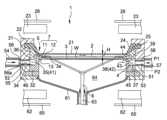
[0015]도 1은 본 발명의 실시예에 따른 에피택셜 성장 장치의 전체 구성을 예시하는 단면도이다.
[0016]도 2는 본 발명의 실시예에 따른 반응 챔버의 구성을 예시하는 분해 사시도이다.
[0017]도 3은 본 발명의 실시예에 따른 반응 챔버의 외측 구성을 예시하는 분해 사시도이다.
[0018]도 4는 본 발명의 실시예에 따른 천장 부분의 구성을 예시하는 사시 단면도이다.
[0019]도 5는 본 발명의 실시예에 따른 측벽의 내측 구성을 개략적으로 예시하는 도면이다.
[0020]도 6은 본 발명의 실시예에 따른 반응 가스 공급 경로를 예시하는 단면도이다.
[0021]도 7a 및 7b는 본 발명의 실시예에 따른 반응 가스 공급 경로를 개략적으로 예시하는 도면들이다.
[0022]도 8a 및 8b는 본 발명의 실시예에 따른 조정 플레이트의 예를 예시하는 사시도들이다.
[0023]도 9는 본 발명의 실시예에 따른 서셉터 링의 예를 예시하는 부분 단면도이다.
[0024]도 10은 본 발명의 실시예에 따른 서셉터 링의 다른 예를 예시하는 부분 단면도이다.
[0025]도 11은 본 발명의 실시예에 따른 서셉터의 예를 예시하는 평면도이다.
[0026]도 12는 본 발명의 실시예에 따른 서셉터의 다른 예를 예시하는 평면도이다.
[0027]도 13은 본 발명의 실시예에 따른 서셉터 지지부의 구성을 개략적으로 예시하는 도면이다.
[0028]도 14는 본 발명의 실시예에 따른 서셉터 샤프트를 예시하는 사시도이다.
[0029]도 15는 본 발명의 실시예에 따른 기판 리프트의 예를 예시하는 사시도이다.
[0030]도 16은 본 발명의 실시예에 따른 가스 배출 튜브의 예를 예시하는 사시 단면도이다.
[0031]도 17은 본 발명의 실시예에 따른 상부 반사체의 예를 예시하는 사시도이다.
[0032]도 18은 본 발명의 실시예에 따른 하부 반사체의 예를 예시하는 평면도이다.
[0033]도 19는 예들 및 비교 예들의 결과들을 예시하는 그래프이다.
[0034]도 20은 관련 기술에 따른, 에피택셜 성장 장치의 천장 부분의 구성을 예시하는 사시 단면도이다.
[0035]도 21은 관련 기술에 따른, 에피택셜 성장 장치의 반응 챔버의 외측 구성을 예시하는 분해 사시도이다.
[0036]도 22는 관련 기술에 따른, 에피택셜 성장 장치의 상부 반사체의 예를 예시하는 평면도이다.
[0037]도 23은 관련 기술에 따른, 에피택셜 성장 장치의 하부 반사체의 예를 예시하는 평면도이다.[0015] Figure 1 is a cross-sectional view illustrating the overall configuration of an epitaxial growth device according to an embodiment of the present invention.
[0016] Figure 2 is an exploded perspective view illustrating the configuration of a reaction chamber according to an embodiment of the present invention.
[0017] Figure 3 is an exploded perspective view illustrating the outer configuration of a reaction chamber according to an embodiment of the present invention.
[0018] Figure 4 is a perspective cross-sectional view illustrating the configuration of a ceiling portion according to an embodiment of the present invention.
[0019] Figure 5 is a diagram schematically illustrating the inner configuration of the side wall according to an embodiment of the present invention.
[0020] Figure 6 is a cross-sectional view illustrating a reaction gas supply path according to an embodiment of the present invention.
[0021] FIGS. 7A and 7B are diagrams schematically illustrating a reaction gas supply path according to an embodiment of the present invention.
[0022] Figures 8A and 8B are perspective views illustrating an example of an adjustment plate according to an embodiment of the present invention.
[0023] Figure 9 is a partial cross-sectional view illustrating an example of a susceptor ring according to an embodiment of the present invention.
[0024] Figure 10 is a partial cross-sectional view illustrating another example of a susceptor ring according to an embodiment of the present invention.
[0025] Figure 11 is a plan view illustrating an example of a susceptor according to an embodiment of the present invention.
[0026] Figure 12 is a plan view illustrating another example of a susceptor according to an embodiment of the present invention.
[0027] Figure 13 is a diagram schematically illustrating the configuration of a susceptor support portion according to an embodiment of the present invention.
[0028] Figure 14 is a perspective view illustrating a susceptor shaft according to an embodiment of the present invention.
[0029] Figure 15 is a perspective view illustrating an example of a substrate lift according to an embodiment of the present invention.
[0030] Figure 16 is a perspective cross-sectional view illustrating an example of a gas exhaust tube according to an embodiment of the present invention.
[0031] Figure 17 is a perspective view illustrating an example of an upper reflector according to an embodiment of the present invention.
[0032] Figure 18 is a plan view illustrating an example of a lower reflector according to an embodiment of the present invention.
[0033] Figure 19 is a graph illustrating the results of examples and comparative examples.
[0034] Figure 20 is a perspective cross-sectional view illustrating the configuration of a ceiling portion of an epitaxial growth device according to the related art.
[0035] Figure 21 is an exploded perspective view illustrating the outer configuration of a reaction chamber of an epitaxial growth device according to the related art.
[0036] Figure 22 is a top view illustrating an example of a top reflector of an epitaxial growth device, according to the related art.
[0037] Figure 23 is a top view illustrating an example of a bottom reflector of an epitaxial growth device, according to the related art.
[0038]이하에서, 본 발명의 실시예에 따른 에피택셜 성장 장치, 및 에피택셜 성장 장치를 사용하여 수행되는 에피택셜 성장을 사용하는 필름 형성 방법이 설명될 것이다.[0038] Hereinafter, an epitaxial growth device according to an embodiment of the present invention and a film forming method using epitaxial growth performed using the epitaxial growth device will be described.
에피택셜 성장 장치의 구성Configuration of the epitaxial growth device
[0039]우선, 본 발명의 실시예에 따른 에피택셜 성장 장치(1)의 구성이 개략적으로 설명될 것이다. 도 1은 에피택셜 성장 장치(1)의 전체 구성을 예시하는 단면도이다. 도 2는 에피택셜 성장 장치(1)의 반응 챔버(2)의 구성을 예시하는 분해 사시도이다. 도 3은 에피택셜 성장 장치(1)의 반응 챔버(2)의 외측 구성을 예시하는 분해 사시도이다.[0039] First, the configuration of the
[0040]에피택셜 성장 장치(1)는, 예를 들어, 실리콘의 필름이 기판(W) 상에서 에피택셜하게 성장할 수 있게 하는 필름 형성 장치이다.[0040] The
[0041]에피택셜 성장 장치(1)는 반응 챔버(2)를 포함한다. 반응 챔버(2)는, 상부에 기판(W)이 장착되는 서셉터(3), 측벽(4), 및 천장(5)을 포함한다.[0041] The epitaxial growth device (1) includes a reaction chamber (2). The
[0042]서셉터(3)는, 상부측으로부터 볼 때 원형 형상을 갖는 플레이트-형 부재이고, 기판(W)보다 약간 더 큰 크기를 갖는다. 서셉터(3)에는, 상부에 기판(W)이 장착되는 기판 오목 부분(3a)이 제공된다. 서셉터(3)는 복수의 아암들(arms)을 갖는 서셉터 지지부(6)에 의해 지지된다.[0042] The
[0043]서셉터 지지부(6)는, 서셉터(3)를 지지하면서, 서셉터(3)를 상향 및 하향으로 리프팅한다. 상부에 기판(W)이 장착되는 서셉터(3)의 표면의 리프팅 범위는, 서셉터(3) 상의 기판(W) 상에 필름이 형성되는 필름-형성 포지션(P1)으로부터, 기판(W)이 에피택셜 성장 장치(1)의 안과 밖으로 옮겨지는(put) 기판-운반 포지션(P2)까지의 범위이다. 서셉터 지지부(6)는, 필름-형성 포지션(P1)에서 서셉터 지지부(6)의 축을 중심으로 회전시키는 것에 의해, 서셉터(3) 및 기판(W)이 회전할 수 있게 하도록 구성된다.[0043] The
[0044]환형 서셉터 링(7)은 필름-형성 포지션(P1)에서 서셉터(3) 주위에 배치된다. 세부 사항들은 이후에 설명되겠지만, 서셉터 링(7)은 제 1 링(11), 및 제 1 링(11) 상에 위치된 제 2 링(12)을 포함한다. 서셉터 링(7)은 반응 챔버(2)의 측벽(4)에 배치된 플랜지 부분(13)에 의해 지지된다.[0044] The annular susceptor ring (7) is arranged around the susceptor (3) in the film-forming position (P1). As details will be explained later, the
[0045]천장 부분(5)은 천장 플레이트(21), 및 천장 플레이트(21)를 지지하는 지지부(22)를 포함한다. 천장 플레이트(21)는 투과성(permeability)을 가지며, 상부 반사체(26) 및 천장 플레이트(21)의 외부 위에 배치된 가열 수단(23)(예를 들어, 할로겐 램프)으로부터의 열을 전달하는 것에 의해 반응 챔버(2)의 내부를 가열시키도록 구성된다. 즉, 본 실시예에 따른 에피택셜 성장 장치(1)는 냉벽(cold wall) 유형의 에피택셜 성장 장치이다. 본 실시예에서, 천장 플레이트(21)는 석영으로 형성된다.[0045] The
[0046]천장 플레이트(21)를 지지하는 지지부(22)는 환형 형상을 갖는다. 천장 플레이트(21)는, 지지부(22)의 내측 엣지 내부의 개구부(24)의, 기판(W)에 근접한, 단부에 고정된다. 고정 방법의 예는 용접 방법이다.[0046] The
[0047]측벽(4)은 환형 상부 측벽(31), 및 환형 하부 측벽(32)을 포함한다. 플랜지 부분(13)은 하부 측벽(32)의 내측 주변 상에 배치된다. 기판 운반 포트(30)는 플랜지 부분(13)의 아래에 배치된다. 상부 측벽(31)은, 상부 측벽(31)의 정상부 표면 상의 지지부(22)의 돌출부(25)의 외부 경사 부분에 대응하는 경사 부분을 갖는다. 지지부(22)는 상부 측벽(31)의 경사부 상에 배치된다.[0047] The side wall 4 includes an annular
[0048]하부 측벽(32)의 정상부 표면에서, 하부 측벽(32)의 외측 주변의 일부는 컷아웃(cut out)되고, 컷아웃이 형성되지 않은 영역은, 상부에 상부 측벽(31)이 장착되는 장착 표면(33)으로서 역할을 한다. 하부 측벽(32)의 컷아웃에 의해, 제 1 오목 부분(34)이 하부 측벽(32)에 형성된다. 즉, 제 1 오목 부분(34)은, 하부 측벽(32)의 정상부 표면의, 장착 표면(33)이 형성되지 않은 일부에 형성된 오목 부분이다. 상부 측벽(31)에서, 제 1 오목 부분(34)의 형상에 대응하고 제 1 오목 부분(34)과 제 1 볼록 부분 사이에 갭(35)을 형성하기 위해, 상부 측벽을 하부 측벽(32) 상에 장착할 때 제 1 오목 부분(34)에 대응하는 포지션에 제 1 볼록(convex) 부분(36)이 형성된다. 제 1 볼록 부분(36)과 제 1 오목 부분(34) 사이의 갭(35)은 반응 가스 공급 경로(공급 경로)(41)로서 역할을 한다. 반응 가스 공급 경로(41)의 세부 사항들은 이후에 설명될 것이다.[0048] On the top surface of the
[0049]하부 측벽(32)의 제 1 오목 부분(34)의 맞은편 영역에서, 하부 측벽(32)의 정상부 표면의 외측 주변 부분의 일부가 컷아웃되어 제 2 오목 부분(37)을 형성한다. 상부 측벽(31)에서, 제 2 오목 부분(37)의 형상에 대응하고 제 2 오목 부분(37)과 제 2 볼록 부분 사이에 갭(38)을 형성하기 위해, 상부 측벽을 하부 측벽(32) 상에 장착할 때 제 2 오목 부분(37)에 대응하는 포지션에 제 2 볼록 부분(39)이 형성된다. 상부 측벽(31)의 제 2 볼록 부분(39) 및 제 2 오목 부분(37)에 의해 가스 배출 경로(42)가 형성된다.[0049] In the area opposite the first recessed
[0050]이러한 방식으로, 반응 가스 공급 경로(41) 및 가스 배출 경로(42)는 반응 챔버(2)에서 서로 대면하며, 반응 챔버(2)에서의 반응 가스는 기판(W) 위를 수평 방향으로 유동한다.[0050] In this way, the reaction
[0051] 하부 측벽(32)의 제 2 오목 부분(37)에 기여하는 벽 표면(43)에 퍼지 홀(44)이 형성되고, 퍼지 가스가 퍼지 홀(44)을 통해 배출된다. 퍼지 홀(44)은 플랜지 부분(13)의 아래에 형성된다. 제 2 오목 부분(37)에 기여하는 벽 표면(43)에 퍼지 홀(44)이 형성되므로, 퍼지 홀(44)은 가스 배출 경로(42)와 소통한다(communicate). 그러므로, 반응 가스 및 퍼지 가스 양자 모두 가스 배출 경로(42)를 통해 배출된다.[0051] A
[0052]환형 플랫폼(45)이 측벽(4)의 하부 측벽(32)의 바닥부 표면 측 상에 배치되어, 측벽(4)이 플랫폼(45) 상에 위치된다.[0052] An
[0053]환형 클램핑 부분(51)은 플랫폼(45), 측벽(4), 및 천장 부분(5)의 외측 주변 측들 상에 배치되고, 그리고 환형 클램핑 부분(51)은 플랫폼(45), 측벽(4), 및 천장 부분(5)을 클램핑하고 지지한다. 클램핑 부분(51)에는, 반응 가스 공급 경로(41)와 소통하는 공급-측 소통 경로(52), 및 가스 배출 경로(42)와 소통하는 배출-측 소통 경로(53)가 제공된다. 가스 도입 튜브(55)가 공급-측 소통 경로(52) 내에 삽입된다. 가스 배출 튜브(58)가 배출-측 소통 경로(53) 내에 삽입된다.[0053] The
[0054]반응 가스 도입 부분(54)은 클램핑 부분(51)의 외부에 배치되고, 그리고 반응 가스 도입 부분(54) 및 공급-측 소통 경로(52)는 서로 소통한다. 본 실시예에서, 제 1 소스 가스 및 제 2 소스 가스는 반응 가스 도입 부분(54)으로부터 도입된다. 제 2 소스 가스는 또한, 캐리어 가스로서 역할을 한다. 셋 또는 그 초과의 유형들의 가스들의 혼합물이 반응 가스로서 사용될 수 있다. 가스 유동 채널에 대해 수직하도록, 조정 플레이트(56)가 반응 가스 도입 부분(54) 및 공급-측 소통 경로(52)의 결합부(joint)에 배치된다. 조정 플레이트(56)에는, 주변을 둘러싸는(circumferential) 방향을 따라 일렬로 복수의 홀들(56a)이 제공되고, 반응 가스로 하여금 홀들(56a)을 통과하게 함으로써 제 1 소스 가스 및 제 2 소스 가스가 혼합되고 조정된다. 가스 배출 부분(57)은 클램핑 부분(51)의 외부에 배치된다. 가스 배출 부분(57)은 반응 가스 도입 부분(54)을 대면하는 포지션에 배치되고, 반응 챔버(2)의 중앙은 가스 배출 부분(57)과 가스 도입 부분(54) 사이에 개재된다.[0054] The reaction
[0055]장치 바닥부 부분(61)은 플랫폼(45)의 내측 주변 측의 하부 부분에 배치된다. 다른 가열 수단(62) 및 하부 반사체(65)가 장치 바닥부 부분(61)의 외부에 배치되어, 기판(W)이 하부측으로부터 가열될 수 있다.[0055] The
[0056]장치 바닥부 부분(61)의 중앙에는, 퍼지 가스 도입 부분(도시되지 않음)이 제공되고, 퍼지 가스 도입 부분을 통해, 서셉터 지지부(6)의 축 부분(63)이 삽입되고 퍼지 가스가 도입된다. 퍼지 가스는, 도시되지 않고 그리고 퍼지 가스 도입 부분에 배치된 퍼지 가스 도입 수단으로부터, 플랫폼(45), 하부 측벽(32), 및 장치 바닥부 부분(61)에 의해 형성된 하부 반응 챔버 부분(64) 내로 도입된다. 퍼지 홀(44)은 하부 반응 챔버 부분(64)과 소통한다.[0056] In the center of the device
에피택셜 성장을 사용하는 필름 형성 방법의 요약Summary of film formation methods using epitaxial growth
[0057]본 실시예에 따른 에피택셜 성장 장치를 사용하는 필름 형성 방법이 이하에서 설명될 것이다.[0057] A film forming method using the epitaxial growth device according to this embodiment will be described below.
[0058]우선, 서셉터(3)가 기판-운반 포지션(P2)으로 이동되고, 기판(W)이 기판 운반 포트(30)로부터 옮겨지며, 그리고 서셉터(3)가 필름-형성 포지션(P1)으로 이동된다. 예를 들어, 200mm의 직경을 갖는 실리콘 기판이 기판(W)으로서 사용된다. 그런 후에, 기판은, 가열 수단(23 및 62)의 사용에 의해, 대기(standby) 온도(예를 들어, 800℃)로부터 성장 온도(예를 들어, 1100℃)로 가열된다. 퍼지 가스(예를 들어, 수소)가 퍼지 가스 도입 부분으로부터 하부 반응 챔버 부분(64) 내로 도입된다. 반응 가스(예를 들어, 제 1 소스 가스로서 트리클로로실란, 및 제 2 소스 가스로서 수소)가 반응 가스 도입 부분(54)으로부터 반응 가스 공급 경로(41)를 통해 반응 챔버(2) 내로 도입된다. 반응 가스는 기판(W)의 표면 상에 경계층을 형성하고, 반응이 경계 층에서 발생한다. 따라서, 실리콘 필름이 기판(W) 상에 형성된다. 반응 가스는, 반응 챔버(2)와 소통하는 가스 배출 경로(42)로부터 배출된다. 퍼지 가스는 퍼지 홀(44)을 통해 가스 배출 경로(42)로 배출된다. 이러한 방식으로 에피택셜 성장이 종료된 후, 온도는 대기 온도로 하락하고, 기판(W)은 꺼내어져서 반도체 제조 장치의 다른 챔버로 이동된다.[0058] First, the
에피택셜 성장 장치를 사용하는 필름 형성 방법의 세부 사항들Details of film formation method using epitaxial growth device
[0059]본 실시예에 따른 에피택셜 성장 장치(1)의 구성 부재들의 세부 사항들 및 본 실시예에 따른 필름 형성 방법의 세부 사항들이 이하에서 설명될 것이다.[0059] Details of the constituent members of the
[0060]도 4는 본 실시예의 천장 부분(5)의 구성을 예시하는 사시 단면도이다. 도면에 도시된 바와 같이, 천장 플레이트(21)를 지지하는 지지부(22)의 내측 엣지는 기판을 향해 천천히 감소하는 직경을 갖는다. 천장 플레이트(21)는, 기판(W)을 대면하는, 내측 엣지의 단부 부분에 고정된다. 지지부(22)를 후면측(rear side)(바닥측)으로부터 보면, 내측 주변 부분이 돌출되어 돌출부(25)를 형성한다. 돌출부(25)는 돌출 방향으로 천천히 감소하는 직경을 갖도록 형성된다. 이러한 방식으로, 지지부(22)는 2개의 경사 부분들을 포함한다. 즉, 지지부(22)는, 천장 플레이트(21)의 주변 엣지에서, 주변 엣지의 외측 및 상부측으로부터 천장 플레이트(21)를 지지한다. 반면에, 도 20은 관련 기술에 따른 에피택셜 성장 장치의 천장 부분(5')의 예를 예시하는 사시 단면도이다. 도면에 도시된 바와 같이, 관련 기술에 따른 장치의 천장 부분(5')에서, 지지부(22')는, 천장 플레이트(21')의 주변 엣지에서, 천장 플레이트(21')와 동일한 평면에서 천장 플레이트(21')를 지지하고, 그리고 지지부(22')는 실질적으로 직사각형 코너(25')를 갖는 형상을 갖는다.[0060] Figure 4 is a perspective cross-sectional view illustrating the configuration of the
[0061]이러한 방식으로, 본 실시예에서, 지지부(22)가, 관련 기술에서보다 응력이 덜 집중되는 그러한 형상으로 형성되기 때문에, 기판(W)과 천장 플레이트(21) 사이의 거리(H)가 감소될 수 있는데, 즉, 10mm 미만으로 감소될 수 있다.[0061] In this way, in this embodiment, the distance H between the substrate W and the
[0062]구체적으로, 가열 수단(23)으로부터의 대부분의 적외선들이 천장 플레이트(21)(21')를 통과하지만, 천장 플레이트(21)(21')는 서셉터(3) 또는 기판(W)으로부터 복사열을 흡수한다. 흡수된 열은 지지부(22)(22')와의 결합부를 통해 천장 플레이트(21)(21')로부터 지지부(22)(22')에 입력된다. 여기서, 기판(W)과 천장 플레이트(21)(21') 사이의 거리(H)가 감소되는 경우, 흡수된 복사열의 양이 증가하여, 지지부(22)(22')로의 열 입력의 양이 증가한다. 그러므로, 관련 기술에서의 천장 부분(5')에서와 같이 지지부(22')가 실질적으로 직사각형 코너(25')를 갖는 경우, 응력이 코너(25') 상에 집중될 수 있어서 크랙들 등을 생성할 수 있다.[0062] Specifically, most of the infrared rays from the heating means 23 pass through the ceiling plate 21 (21'), but the ceiling plate 21 (21') is connected to the
[0063]반면에, 본 실시예에서, 지지부(22)에 돌출부(25)를 형성하고, 천장 플레이트(21)의 주변 엣지에서, 주변 엣지의 외측 및 상부측으로부터 천장 플레이트(21)를 지지하는 것에 의해, 천장 플레이트(21)는, 가능한 작게 응력이 쉽게 집중되는 코너(25')를 형성하는 것 없이, 기판 측에 대해 지지될 수 있다.[0063] On the other hand, in the present embodiment, a
[0064]본 실시예에서, 상기 셜명된 바와 같이 경계 층을 협소하게 하기 위해 천장 플레이트(21)와 기판(W) 사이의 거리가 감소되기 때문에, 반응 가스가 기판(W)의 외부로 빠져나갈 가능성이 있고 기판의 필름 두께 분포가 잘 균일화되지(uniformized) 않을 수 있는데, 이는 바람직하게는, 방지되어야 한다. 따라서, 본 실시예에서, 이하에서 설명되는 바와 같이, 가스 유동을 균일화하기 위해, 반응 가스 공급 경로(41)에 가이드 부분이 배치된다.[0064] In this embodiment, since the distance between the
[0065]반응 가스 공급 경로(41)에 배치된 가이드 부분은 도 5 내지 7b와 관련하여 이하에서 상세하게 설명될 것이다. 상기 설명된 바와 같이, 반응 가스 공급 경로(41)는 하부 측벽(32)의 제 1 오목 부분(34) 및 상부 측벽(31)의 제 1 볼록 부분(36)에 의해 형성되고, 공급-측 소통 경로(52)의 가스 도입 튜브(55)를 통해 반응 가스 도입 부분(54)과 소통한다. 반응 가스 공급 경로(41)는, 반응 가스 도입 부분(54)으로부터의 가스 도입 방향에 대응하는 방향(수평 방향)으로 연장되는 제 1 공급 경로(71), 가스 도입 방향에 수직인 방향(수직 방향)으로 연장되고, 제 1 공급 경로(71)와 소통하는 제 2 공급 경로(72), 및 가스 도입 방향에 평행한 방향(수평 방향)으로 연장되고, 제 2 공급 경로(72)와 소통하는 제 3 공급 경로(73)를 포함한다. 제 3 공급 경로(73)는 반응 챔버(2)와 소통한다. 즉, 반응 가스 공급 경로(41)는, 반응 가스의 입구인 공급-측 소통 경로(52)로부터, 반응 가스의 출구이며 반응 챔버(2)에 연결된 출구로 상승하는 계단형으로 형성된다.[0065] The guide portion disposed in the reaction
[0066]여기서, 제 2 공급 경로(72)는 상기 설명된 바와 같이 수직 방향으로 연장되기 때문에, 반응 가스 도입 부분으로부터 도입된 가스는, 반응 가스 도입 부분(54)을 대면하는, 제 2 공급 경로(72)의 벽 표면(74)과 접촉하게 된다. 따라서, 반응 가스가 확산되어(diffused), 반응 가스의 혼합 특성이 개선된다. 즉, 제 2 공급 경로(72)는 반응 가스의 혼합 챔버로서 역할을 한다. 이러한 경우에, 본 실시예에서, 반응 가스가 제 2 공급 경로(72)에 머물지 않도록, 수직 방향으로 연장되는 그루브(75)가 제 2 공급 경로(72)의 벽 표면(74)에 형성되고, 그루브(75)는 가이드 부분으로서 역할을 한다. 그루브(75)가 이러한 방식으로 형성되기 때문에, 제 2 공급 경로(72)의 벽 표면(74)과의 접촉에 의해 확산된 가스는, 제 3 공급 경로(73) 내로 쉽게 유동할 수 있고, 그루브(75)를 따라 조정되어 반응 가스의 직선적 유동 특성을 개선할 수 있으며, 이로써, 반응 가스가 반응 챔버(2)에서 유동할 때, 반응 가스의 확산을 억제한다.[0066] Here, since the second supply path 72 extends in the vertical direction as described above, the gas introduced from the reactive gas introduction portion is directed to the second supply path facing the reactive
[0067]그루브(75)는 이하에서 상세하게 설명될 것이다. 복수의 그루브들(75)이, 제 2 공급 경로(72)의 벽 표면(74)의 전체 표면에서 오목 부분으로서 연속적으로 형성된다. 도 7b에 도시된 바와 같이, 본 실시예에서, 오목 부분으로서의 그루브들(75)은 그루브들의 폭 방향으로 만곡되며(curved), 정상부 측으로부터 볼 때, 각각의 그루브(75)는 호(arc) 형상으로 보인다. 그루브(75)가 폭 방향으로 만곡되기 때문에, 반응 가스가 벽 표면(74)의 그루브들(75)의 바닥부와 접촉하게 될 때, 반응 가스는, 확산될 가능성이 없고(농축될(concentrated) 가능성이 있고), 반응 가스가 반응 챔버(2)에서 유동할 때, 기판(W)의 외부로 확산될 가능성이 없다. 그루브들(75)의 깊이가 과도하게 크면, 확산은 억제될 수 있지만, 반응 가스의 제 1 소스 가스 및 제 2 소스 가스가 혼합될 가능성이 없다. 본 발명의 실시예에서, 그루브들(75)의 깊이는 바람직하게, 1mm 내지 5mm의 범위로 설정되고, 더 바람직하게는, 3mm로 설정된다.[0067] The groove 75 will be described in detail below. A plurality of grooves 75 are continuously formed as recesses on the entire surface of the wall surface 74 of the second supply path 72 . As shown in FIG. 7B, in this embodiment, the grooves 75 as concave portions are curved in the width direction of the grooves, and when viewed from the top side, each groove 75 has an arc. It looks like a shape. Because the grooves 75 are curved in the width direction, when the reaction gas comes into contact with the bottom of the grooves 75 of the wall surface 74, the reaction gas is not likely to diffuse (and become concentrated). possibility), when the reaction gas flows in the
[0068]그루브들(75)은 하부 측벽(32)의 평면-내 방향(in-plane direction)으로 중앙(c)을 향해 형성된다. 즉, 그루브들(75)은 하부 측벽(32)의 주변 방향을 따라서 배열된다. 그루브들을 이러한 방식으로 배열하는 것에 의해, 그루브들(75)에 의해 가이딩되고 반응 챔버(2) 내로 도입되는 반응 가스의 유동 방향의 수평 컴포넌트가, 반응 챔버(2)를 대면하는, 반응 가스 공급 경로(41)의 개구부의 중앙으로부터, 반응 챔버(2)의 중앙으로 연장되는 방향의 수평 컴포넌트에 대응하도록 조정 특성이 강화될 수 있고, 이로써, 반응 챔버(2)에서 반응 가스의 확산을 억제한다.[0068] The grooves 75 are formed in the in-plane direction of the
[0069]그루브들(75)은, 각각의 그루브(75)의 폭 방향의 중심이, 반응 가스 도입 부분(54)에 배치된 조정 플레이트(56)의 각각의 홀(56a)의 중심에 실질적으로 일치하는(agree)(대응하는) 포지션들에서 형성된다. 즉, 본 실시예에서, 벽 표면(74)의 그루브들(75)의 개수는 홀들(56a)의 개수와 동일하다. 따라서, 조정 플레이트(56)에 의해 조정된 반응 가스가 그루브들(75)에서 유동하기 때문에, 조정 성능이 더 강화되어, 반응 가스의 직선적 유동 특성을 개선한다.[0069] The grooves 75 are such that the width direction center of each groove 75 is substantially at the center of each
[0070]본 실시예에서, 그루브들(75)은 제 2 공급 경로(72)의 벽 표면(74)의 전체 표면에 형성되지만, 제 2 공급 경로(72)의 벽 표면(74)의 적어도 단부 부분에서 형성될 수 있다. 조정 플레이트(56)의 홀들이 복수의 영역들로 분할되고, 단부 부분은, 그러한 복수의 영역들의 최단부 영역에 대응하는 부분을 의미한다. 예를 들어, 도 7a 및 7b에 도시된 예에서, 조정 플레이트(56)는 3개의 영역들(81)로 분할되고, 그루브들(75)은 오직 최단부 영역들(82 및 83)의 홀들에 대응하도록 형성되어야 한다. 상기 설명된 바와 같이 반응 가스가 기판(W)의 외부로 빠져나갈 가능성이 있기 때문에, 반응 가스 공급 경로(41)의 단부 부분들에서 반응 가스의 직선적 유동 특성을 강화하도록 그루브들(75)이 형성되는 것이 특히 바람직하다. 이러한 경우에, 오목 부분의 형태의 가이드로서 역할을 하는 그루브들(75)을 형성하는 것에 의해, 그러한 효과를 쉽게 획득하는 것이 가능하다. 예를 들어, 조정 부재가 제 2 공급 경로(72)와 분리되어 배치되는 경우, 반응 가스의 혼합 특성 또는 제조 비용에서 문제가 발생할 수 있다. 그러나, 그러한 문제는, 본 실시예에서와 같은 오목 부분으로서 그루브들(75)을 형성함으로써 해결된다.[0070] In this embodiment, the grooves 75 are formed on the entire surface of the wall surface 74 of the second supply path 72, but at least on an end of the wall surface 74 of the second supply path 72. It can be formed in parts. The holes of the
[0071]도 8a 및 8b는 조정 플레이트(56)의 예를 예시하는 사시도들이다. 도면들에서 도시된 바와 같이, 조정 플레이트(56)는 오직 그루브들(75)의 패턴을 따르도록 준비되어야 한다. 조정 플레이트(56)의 개구부 비율은 바람직하게, 스크러버와 같은 부수적인 장비, 또는 외부 파이프의 형상, 및 길이 등뿐만 아니라 성장 레이트의 관점을 고려한 최적 값이 되도록 결정된다.[0071] Figures 8A and 8B are perspective views illustrating an example of an
[0072]본 실시예에서, 상기 설명된 바와 같이 경계 층을 협소하게 하기 위해 천장 플레이트(21)와 기판(W) 사이의 거리가 감소되기 때문에, 반응 가스는 반응 챔버(2)의 하부 부분 내로 쉽게 유동할 수 있고, 기판(W)의 온도 분포가 균일화될 가능성이 없을 수 있다. 결과적으로, 두꺼운 필름을 형성할 때, 필름 두께 분포 또는 필름 품질의 열화(degradation)(예를 들어, 저항률의 분포 또는 결정 결함들의 발생)가 야기될 수 있다. 본 실시예에서, 이러한 문제들을 방지하기 위해, 서셉터 링(7)이 2개의 부재들에 의해 형성된다. 이 점은 이하에서 설명될 것이다.[0072] In this embodiment, since the distance between the
[0073]도 9에서 확대된 것과 같이, 서셉터 링(7)의 제 1 링(11)은 서셉터의 외측 주변으로부터 이격되어 배치되고, 계단형 부분(91)은 제 1 링의 내측 주변에 형성된 낮은 정상부 표면을 갖는다. 제 2 링(12)은 계단형 부분(91) 상에 위치되고, 그리고 제 2 링(12)은, 제 1 링(11)과 서셉터(3) 사이에 형성된 공극(clearance) 부분(92)을 대면하도록, 즉, 공극 부분(92)으로 돌출되도록 형성된다. 제 2 링(12)은, 제 2 링(12)의 정상부 표면이 서셉터(3)의 정상부 표면과 수평을 이루도록(flush) 배치된다. 이러한 방식으로 제 2 링(12)의 정상부 표면이 서셉터(3)의 정상부 표면과 수평을 이루도록 만드는 것에 의해, 반응 가스 공급 경로(41) 등에서 혼합되고 조정된 상태로 유지되는 반응 가스가, 가능한 많이 유량을 낮추는 것 없이, 기판(W)에 원활하게(smoothly) 공급될 수 있다. 본원에서 언급되는 서셉터(3)의 정상부 표면은 기판 오목 부분(3a)(도 1, 2, 11, 및 12 참고)이 형성되지 않은 영역의 서셉터(3)의 정상부 표면을 의미한다. 본 실시예의 제 2 링(12)은 열 전도성을 고려하여 실리콘 탄화물로 형성된다.[0073] As enlarged in Figure 9, the
[0074]이러한 방식으로 상이한 부재들로부터 제 1 링(11) 및 제 2 링(12)을 형성하는 것에 의해, 서셉터 링(7)이 더 높은 정확도로 구성될 수 있다. 즉, 서셉터 링(7)과 서셉터(3) 사이의 거리가 한계까지 감소될 수 있고, 따라서, 기판(W)의 후면측, 즉, 반응 챔버의 바닥측(64)으로의 반응 가스의 유동을 감소시키는 것, 그리고 기판(W)의 온도 분포를 균일화하는 것이 가능하다. 결과적으로, 본 실시예에 따라, 형성된 필름의 필름 품질 분포 또는 필름 두께 분포가 균일화된다.[0074] By forming the
[0075]제 1 링(11) 및 제 2 링(12)으로 이루어진 2개의 부재들을 제공하는 것에 의해, 제 1 링(11)과 제 2 링(12) 사이의 열의 전도가, 제 1 링(11) 및 제 2 링(12)이 단일 부재로 형성되는 경우보다 더 억제될 수 있다.[0075] By providing two members consisting of a
[0076]이러한 방식으로 제 2 링(12)으로 하여금 공극 부분(92)을 대면하게 하는 것에 의해, 필름을 형성할 때, 서셉터 링(7)과 서셉터(3) 사이로부터 하부 측으로 향하는 반응 가스의 누설을 감소시키는 것이 가능하고, 따라서, 반응 가스의 유동은 교란될(disturbed) 가능성이 없다. 하부 측으로의 반응 가스의 누설이 감소될 수 있기 때문에, 입자들을 감소시키는 것이 가능하다.[0076] By making the
[0077]이러한 경우에, 제 2 링(12)은 제 1 링(11)보다 더 얇다. 따라서, 복사에 의한, 서셉터(3)로부터의 열 손실을 억제하는 것이 가능하다. 제 2 링(12)이 더 얇기 때문에, 제 2 링(12)을 미리 결정된 고온으로 유지하기(예열하기) 위한 열의 양을 감소시키는 것이 가능하다. 다른 실시예에서, 제 1 링(11)이, 작은 열 전도성을 갖는 재료로 형성되는 경우, 제 1 링(11)은 열 절연체로서 역할을 하고, 이로써, 상기-언급된 효과를 더 강화한다.[0077] In this case, the
[0078]본 실시예에서, 제 2 링(12)은 공극 부분(92)을 대면하도록 구성되지만, 본 발명은 이러한 구성에 제한되지는 않는다. 서셉터 링(7)은, 제 2 링(12)이 적어도, 제 1 링(11)의 계단형 부분(91) 상에 위치되는 한, 높은 정밀도로 구성될 수 있다. 따라서, 서셉터 링(7)과 서셉터(3) 사이의 거리는 한계까지 감소될 수 있고, 따라서, 기판(W)의 후면측으로의 반응 가스의 유동을 감소시키는 것, 그리고 기판의 온도 분포를 균일화하는 것이 가능하다.[0078] In this embodiment, the
[0079]본 실시예에서, 경계 층을 협소하게 하기 위해 천장 플레이트(21)와 기판(W) 사이의 거리가 감소되기 때문에, 천장 플레이트(21)의 천장 표면은 반응 가스로 쉽게 코팅될 수 있다. 천장 표면이 코팅되는 경우, 천장 표면이 흐려질(bedimmed) 수 있고, 따라서, 필름은, 가열 수단(23)을 사용하여 천장 플레이트(21)를 통해 가열되는 냉벽 유형의 에피택셜 성장 장치를 사용하여, 만족스럽게 형성되지 않을 수 있다. 이와 반대로, 본 실시예에서, 반응 가스 공급 경로(41)의 벽 표면에 그루브들(75)을 형성하는 것 그리고 상기 설명된 바와 같이 2개의 부재들로부터 서셉터 링(7)을 형성하는 것에 의해, 반응 가스가 반응 챔버(2)에 머무를 가능성이 없고, 따라서, 코팅 재료의 부착을 억제하는 것이 가능하다. 결과적으로, 필름을 연속적으로 그리고 만족스럽게 형성하는 것이 가능하다.[0079] In this embodiment, since the distance between the
[0080]도 10은 서셉터 링(7)의 수정 예를 도시한다. 이러한 수정 예는, 제 2 링(12A)이 공극 부분(92A)을 커버하도록 배치되는 점에서, 도 9에 도시된 실시예와 상이하다. 이러한 수정 예에서, 제 1 링(11A)은 측벽(32A)의 플랜지 부분(13A) 상에 위치된다. 제 2 링(12A)은 제 1 링(11A)의 계단형 부분(91A) 상에 위치되고, 내측 주변은 서셉터(3A)의 외측 주변과 대면한다.[0080] Figure 10 shows a modified example of the
[0081]이러한 수정 예에서, 제 2 링(12A)이 공극 부분(92A)을 커버하도록 배치되기 때문에, 반응 챔버(2A) 내로 유동하는 반응 가스의, 하부 반응 챔버 부분(64A)으로의 유동을 더 억제하는 것이 가능하다. 여기서, 제 2 링(12A)이, 도 10에 도시되지 않은 가열 수단(23)으로부터의 서셉터(3A)의 가열을 차단하는 것을 방지하기 위해, 제 2 링(12A) 및 서셉터(3A)의 겹치는 지역이 작은 것이 바람직하다.[0081] In this modified example, because the second ring 12A is arranged to cover the void portion 92A, it prevents the flow of reaction gas flowing into the reaction chamber 2A into the lower reaction chamber portion 64A. Further suppression is possible. Here, in order to prevent the second ring 12A from blocking heating of the susceptor 3A from the heating means 23 not shown in FIG. 10, the second ring 12A and the susceptor 3A It is desirable for the overlapping area to be small.
[0082]이러한 수정 예에서, 제 2 링(12A)의 두께는 바람직하게, 예를 들어, 0.5mm 내지 2mm의 범위로 설정되고, 더 바람직하게는, 약 0.8mm로 설정된다. 이러한 두께를 설정하는 것에 의해, 서셉터(3A)로부터 제 2 링(12A)으로의 복사에 기인한 열 손실을 가능한 많이 억제하는 것이 가능하다.[0082] In this modification, the thickness of the second ring 12A is preferably set, for example, in the range of 0.5 mm to 2 mm, more preferably about 0.8 mm. By setting this thickness, it is possible to suppress heat loss due to radiation from the susceptor 3A to the second ring 12A as much as possible.
[0083]도 11 및 12는 본 발명의 실시예에 따른 서셉터(3)의 예들을 예시하는 평면도들이다. 도면들에 도시된 바와 같이, 서셉터들(3A 및 3B)에는, 리프트 핀들(123)(도 13 참고)이 통과하는 리프트-핀 관통-홀들(110A 및 110B)이 제공된다. 도 12에 도시된 바와 같이, 복수의 관통-홀들(111B)이 형성될 수 있다. 기판을 서셉터 상에 위치시키고 그리고 기판(W)이 수평 방향으로 슬라이딩될 때 기판과 서셉터 사이의 가스가 누설될 수 있는 문제가 관통-홀들(111B)에 의해 해결될 수 있다. 이러한 서셉터(3B)가 사용되는 경우, 기판(W)의 저항률 분포 또는 필름 두께 분포의 균일화는, 서셉터(3A)가 사용되는 경우보다 우수하다. 이는, 관통-홀들(111B)의 직경이 더 작아지고, 관통-홀들(111B)의 개수가 더 많아지는 경우, 더 두드러진다(marked). 개구부 비율이 4% 초과인 것이 바람직하고, 그리고 관통-홀들(111B)이, 기판 오목 부분뿐만 아니라, 서셉터의 기판 오목 부분(3Ba) 주위에 형성되는 것이 더 바람직하다.[0083] Figures 11 and 12 are top views illustrating examples of the
[0084]도 13 내지 16은 서셉터 지지부(6)의 예들을 도시한다. 도 13에 도시된 바와 같이, 서셉터 지지부(6)는 서셉터 샤프트(121), 기판 리프트(122), 및 리프트 핀들(123)을 포함한다. 서셉터(3)는 서셉터 샤프트(121)의 3개의 아암들에 의해 둘러싸인다. 기판 리프트(122)의 3개의 아암들에는, 오목 부분을 갖는 페데스탈들(124)이 제공되고, 그러한 오목 부분들 상에, 각각, 대응하는 리프트 핀(123)의 하부 단부가 위치된다. 기판 리프트(122)의 축 부분은 원통 형상으로 형성되고, 서셉터 샤프트(121)의 축 부분은 기판 리프트(122)의 축 부분 내로 삽입될 수 있다.[0084] Figures 13 to 16 show examples of susceptor supports 6. As shown in FIG. 13 , the
[0085]본 실시예에서, 서셉터 지지부(6)의 아암들은 관련 기술에서보다 더 작은 두께를 갖는다. 따라서, 가열 수단(62)의 사용에 의해 서셉터(3) 상의 기판(W)을 가열할 때 서셉터 지지부(6)의 영향이 감소될 수 있기 때문에, 서셉터(3)의 온도 분포를 균일화하는 것이 가능하다. 실시예의 서셉터 지지부(6)의 상세한 구성 및 리프팅 작동은, 본 발명의 출원인에 의해 출원된 국제 공보 WO2013/005481의 팜플렛에 설명된 서셉터 장치에서와 동일하다. 그러나, 국제 공보의 팜플렛에 설명된 서셉터 장치는 단일 서셉터 샤프트(플랫폼 샤프트)를 포함하지만, 본 실시예의 서셉터 지지부(6)는 3개의 서셉터 샤프트들(아암들)(121)을 포함한다.[0085] In this embodiment, the arms of the
[0086]도 16은 본 실시예의 가스 배출 튜브(58)의 예를 예시하는 사시 단면도이다. 도면에 도시된 바와 같이, 가스 배출 튜브(58)는, 개구부가, 반응 챔버(2)로부터 가스 배출 부분(57)으로, 중앙을 향하여 협소해지도록 형성된다. 따라서, 중앙에서 배기가 조정되고, 이로써, 배기 효율을 개선한다.[0086] Figure 16 is a perspective cross-sectional view illustrating an example of a
[0087]도 21은 관련 기술에 따른 에피택셜 성장 장치의 반응 챔버(2)의 외측 구성을 예시하는 분해 사시도이다. 도면에 도시된 바와 같이, 가스 도입 튜브(55) 및 가스 배출 튜브(58)와 가스 도입 튜브(55') 및 가스 배출 튜브(58')를 비교하면, 튜브들의 중앙 부분들에서의 마감 처리된(finished) 부분들이, 본 실시예에서 제거된다. 따라서, 필름 두께 분포에 영향을 주는 가스의 유동이 원활해진다.[0087] Figure 21 is an exploded perspective view illustrating the outer configuration of the
[0088]퍼지 홀(44) 및 가스 배출 경로(42)의 개구부 비율이 과도하게 큰 경우, 반응 가스는 하부 반응 챔버 부분(64) 내로 유동하고, 개구부 비율이 과도하게 작은 경우, 퍼지 가스는 반응 챔버(2)에서의 필름 형성 프로세스에 영향을 준다. 따라서, 개구부 비율들이 최적 값들을 갖도록 가스 배출 경로의 개구부들이 형성된다.[0088] If the opening ratio of the
[0089]도 17은 본 발명의 실시예에 따른 상부 반사체(26)의 예를 예시하는 사시도이다. 도면에 도시된 바와 같이, 상부 반사체(26)는 가열 수단(23)으로부터의 열선들을 반응 챔버(2)의 중앙으로 반사시키는 경사 부분들(26a), 및 가열 수단(23)으로부터의 열선들을 수직-하향 방향으로 반사시키는 편평 부분들(26b)을 포함한다. 반면에, 도 22는 관련 기술에 따른 에피택셜 성장 장치의 상부 반사체(26')의 예를 예시하는 사시도이다. 도면에 도시된 바와 같이, 관련 기술의 상부 반사체(26')는 경사 부분들(26a') 및 편평 부분들(26b')을 포함하지만, 경사 부분들(26a)의 배열에서, 본 발명의 실시예에 따른 상부 반사체(26)와 상이하다. 구체적으로, 본 발명의 실시예에 따른 상부 반사체(26)는, 경사 부분이, 관련 기술의 상부 반사체(26')의 편평 부분(26b')의 중앙에 부가되는 배열을 갖는다. 이러한 방식에서, 경사 부분들(26a) 및 편평 부분들(26b)의 지역 비율이 미리 결정된 비율이 되도록, 그리고 경사 부분들(26a) 및 편평 부분들(26b)의 분포가 편향되지 않도록 경사 부분들(26a) 및 편평 부분들(26b)을 배열하는 것에 의해, 기판(W)의 온도 분포의 균일화가 달성된다.[0089] Figure 17 is a perspective view illustrating an example of the
[0090]도 18은 본 발명의 실시예에 따른 하부 반사체(65)의 예를 예시하는 사시도이다. 도 23은 관련 기술에 따른 에피택셜 성장 장치의 하부 반사체(65')의 예를 예시하는 사시도이다. 상부 반사체(26)와 유사하게, 하부 반사체(65)는, 가열 수단(62)으로부터의 열선들을 반응 챔버(2)의 중앙으로 반사시키는 경사 부분들(65a), 및 가열 수단(62)으로부터의 열선들을 수직-상향 방향으로 반사시키는 편평 부분들(65b)을 포함하고, 경사 부분이, 관련 기술에 따른 하부 반사체(65')의 편평 부분(65b')의 중앙에 부가되는 배열을 갖는다. 이러한 방식에서, 경사 부분들(65a) 및 편평 부분들(65b)의 지역 비율이 미리 결정된 비율이 되도록, 그리고 경사 부분들(65a) 및 편평 부분들(65b)의 분포가 편향되지 않도록 경사 부분들(65a) 및 편평 부분들(65b)을 배열하는 것에 의해, 기판(W)의 온도 분포의 균일화가 달성된다.[0090] Figure 18 is a perspective view illustrating an example of the
[0091]본 실시예에 따른 에피택셜 성장 장치에서, 지지부(22)가 천장 플레이트(21)를 지지하기 때문에, 반응 챔버를 대면하는, 천장 플레이트(21)의 중앙 부분의 천장 표면과 기판(W) 사이의 거리(H)는 10mm 미만으로 설정될 수 있다. 따라서, 본 실시예에 따른 에피택셜 성장 장치(1)는, 천장 플레이트(21)와 서셉터(3) 사이에서 유동하는 반응 가스에 의해 형성된 경계 층이, 천장을 향해 퍼지는(spreading) 것을 방지할 수 있고, 따라서, 경계 층은 협소해진다. 그런 후에, 경계 층에서의 유량이 증가하기 때문에, 결과적으로 가스 밀도가 증가하고, 따라서, 기판(W)의 표면 상에서의 반응 효율을 강화하는 것이 가능하다. 따라서, 에피택셜 성장 장치(1)에서, 성장 레이트를 강화하는 것이 가능하다.[0091] In the epitaxial growth device according to the present embodiment, since the
[0092]본 발명의 실시예에서, 천장 플레이트(21)와 기판(W) 사이의 거리(H)는 10mm 미만이고, 천장 플레이트(21)와 기판(W) 사이의 거리(H)가 10mm 미만인 것과 기판(W) 상에 형성된 필름으로부터 천장 플레이트(21) 까지의 거리가 1mm와 동일하거나 그 초과인 것이 바람직하다. 이러한 범위를 설정하는 것에 의해, 경계 층을 형성하면서 반응 가스의 가스 유동을 원활하게 하는 것이 가능하다.[0092] In an embodiment of the present invention, the distance (H) between the
[0093]즉, 본 실시예의 반응 챔버(2)에서, 기판(W)과 천장 플레이트(21) 사이의 거리를, 관련 기술(관련 기술에서는 약 20mm)에서보다 더 작도록 설정하는 것에 의해, 경계 층을 협소하게 하여 기판의 표면 상에서의 반응 효율을 강화하고, 따라서 성장 레이트를 상승시키는 것이 가능하다.[0093] That is, in the
예들examples
[0094]본 발명은 예들과 관련하여 이하에서 상세하게 설명될 것이다.[0094] The invention will be explained in detail below with reference to examples.
예 1Example 1
[0095]에피택셜 성장은 이하의 성장 조건들 하에서, 도 10에 도시된 서셉터 링을 채용하는 에피택셜 성장 장치(1A)(장치에서, 기판(W)의 표면과 천장 플레이트(21) 사이의 거리(H)는 9.27mm)의 사용에 의해 수행되었다.[0095] Epitaxial growth is performed using an epitaxial growth device 1A employing the susceptor ring shown in FIG. 10 (in the device, between the surface of the substrate W and the ceiling plate 21) under the following growth conditions. Distance (H) was performed by using 9.27 mm).
제 1 소스 가스(트리클로로실란)의 양 : 8.5SLMAmount of first source gas (trichlorosilane): 8.5SLM
퍼지 가스(수소)의 양 : 15.0SLMAmount of purge gas (hydrogen): 15.0SLM
성장 시간 : 600.0초Growth time: 600.0 seconds
성장 온도 : 1100.0℃Growth temperature: 1100.0℃
회전 속도 : 20.0RPMRotation speed: 20.0RPM
예 2Example 2
[0096]에피택셜 성장은, 제 1 소스 가스의 양이 13.5SLM으로 변경된 것을 제외하고, 예 1의 조건들과 동일한 조건들 하에서 수행되었다.[0096] Epitaxial growth was performed under the same conditions as those in Example 1, except that the amount of first source gas was changed to 13.5 SLM.
예 3Example 3
[0097]에피택셜 성장은, 제 1 소스 가스의 양이 17.0SLM으로 변경된 것을 제외하고, 예 1의 조건들과 동일한 조건들 하에서 수행되었다.[0097] Epitaxial growth was performed under the same conditions as those in Example 1, except that the amount of first source gas was changed to 17.0 SLM.
비교 예 1Comparison example 1
[0098]에피택셜 성장은, 회전 속도가 35.0RPM으로 변경된 것을 제외하고, 예 1의 조건들과 동일한 조건들 하에서, 관련 기술에 따른 에피택셜 성장 장치(장치에서, 기판(W)의 표면과 천장 플레이트(21) 사이의 거리(H)는 20mm였고, 그루브(75)가 없었으며, 서셉터 링은 단일 부재로 형성되었음)를 사용하여 수행되었다.[0098] Epitaxial growth is an epitaxial growth device (in the device, the surface and ceiling of the substrate W) according to the related art, under the same conditions as those of Example 1, except that the rotation speed was changed to 35.0 RPM The distance H between the
비교 예 2Comparison example 2
[0099]에피택셜 성장은, 회전 속도가 35.0RPM으로 변경된 것을 제외하고, 예 2의 조건들과 동일한 조건들 하에서, 관련 기술에 따른 에피택셜 성장 장치(장치에서, 기판(W)의 표면과 천장 플레이트(21) 사이의 거리(H)는 20mm였고, 그루브(75)가 없었으며, 서셉터 링은 단일 부재로 형성되었음)를 사용하여 수행되었다.[0099] Epitaxial growth is an epitaxial growth device according to the related art (in the device, the surface and ceiling of the substrate W) under the same conditions as those of Example 2, except that the rotation speed was changed to 35.0 RPM The distance H between the
비교 예 3Comparison example 3
[00100]에피택셜 성장은, 회전 속도가 35.0RPM으로 변경된 것을 제외하고, 예 3의 조건들과 동일한 조건들 하에서, 관련 기술에 따른 에피택셜 성장 장치(장치에서, 기판(W)의 표면과 천장 플레이트(21) 사이의 거리(H)는 20mm였고, 그루브(75)가 없었으며, 서셉터 링은 단일 부재로 형성되었음)를 사용하여 수행되었다.[00100] Epitaxial growth is an epitaxial growth device (in the device, the surface and ceiling of the substrate W) according to the related art, under the same conditions as those of Example 3, except that the rotation speed was changed to 35.0 RPM The distance H between the
[00101]예들 및 비교 예들에서의 필름 성장 레이트가 검출되었다. 검출된 성장 레이트들과 제 1 소스 가스의 관계가 도 19에 도시된다.[00101] Film growth rates in examples and comparative examples were detected. The relationship between the detected growth rates and the first source gas is shown in Figure 19.
[00102]도 19에 도시된 바와 같이, 본 발명의 실시예에 따른 에피택셜 성장 장치(1A)를 채용하는 것에 의해, 성장 레이트가 50%만큼 개선되었고, 제 1 소스 가스의 양이 증가되었을 때, 성장 레이트의 개선이 증가되었다. 따라서, 성장 레이트는 본 실시예에 따른 에피택셜 성장 장치를 사용함으로써 강화되었다.[00102] As shown in Figure 19, by employing the epitaxial growth device 1A according to an embodiment of the present invention, the growth rate was improved by 50% and when the amount of the first source gas was increased , the improvement in growth rate was increased. Accordingly, the growth rate was enhanced by using the epitaxial growth device according to this embodiment.
Claims (35)
Translated fromKorean링 형상 지지부; 및
천장 플레이트를 포함하고,
상기 링 형상 지지부는,
정상 표면 및 바닥 표면을 갖는 본체; 및
상기 본체의 바닥 표면으로부터 내측 및 하측으로 돌출된 돌출부 ― 상기 돌출부는 제 1 경사 부분 및 제 2 경사 부분을 갖고, 상기 제 1 경사 부분은 상기 링 형상 지지부의 내부 표면의 일부이며, 상기 제 1 및 제 2 경사 부분들은 상기 링 형상 지지부의 중심을 향하여 직경이 감소됨 ―를 포함하고,
상기 천장 플레이트는 상기 링 형상 지지부의 돌출부에 커플링되는,
프로세싱 장치에서 사용하기 위한 천장 부분.A ceiling portion for use in a processing device, the ceiling portion comprising:
Ring-shaped support portion; and
Includes a ceiling plate,
The ring-shaped support part,
a body having a top surface and a bottom surface; and
a protrusion projecting inwardly and downwardly from the bottom surface of the body, the protrusion having a first inclined portion and a second inclined portion, the first inclined portion being a part of the inner surface of the ring-shaped support, the first and The second inclined portions comprise a decreasing diameter towards the center of the ring-shaped support,
The ceiling plate is coupled to the protrusion of the ring-shaped support,
Ceiling section for use in processing units.
상기 천장 플레이트는 상기 링 형상 지지부의 내부 표면에 고정되는,
프로세싱 장치에서 사용하기 위한 천장 부분.According to claim 1,
The ceiling plate is fixed to the inner surface of the ring-shaped support,
Ceiling section for use in processing units.
상기 돌출부의 주변 엣지는 상기 천장 플레이트의 주변 엣지에서 상기 천장 플레이트를 지지하는,
프로세싱 장치에서 사용하기 위한 천장 부분.According to claim 1,
The peripheral edge of the protrusion supports the ceiling plate at the peripheral edge of the ceiling plate,
Ceiling section for use in processing units.
상기 천장 플레이트는 광 투과성 재료로 제조되는,
프로세싱 장치에서 사용하기 위한 천장 부분.According to claim 1,
wherein the ceiling plate is made of a light-transmissive material,
Ceiling section for use in processing units.
상기 제 1 경사 부분 및 상기 제 2 경사 부분은 상기 천장 플레이트에서 만나는,
프로세싱 장치에서 사용하기 위한 천장 부분.According to claim 1,
The first inclined portion and the second inclined portion meet at the ceiling plate,
Ceiling section for use in processing units.
상기 제 1 경사 부분 및 상기 제 2 경사 부분에 의해 형성된 각도가 90도 미만인,
프로세싱 장치에서 사용하기 위한 천장 부분.According to claim 5,
wherein the angle formed by the first inclined portion and the second inclined portion is less than 90 degrees,
Ceiling section for use in processing units.
상기 천장 플레이트는 복사열을 흡수하도록 구성되는,
프로세싱 장치에서 사용하기 위한 천장 부분.According to claim 1,
The ceiling plate is configured to absorb radiant heat,
Ceiling section for use in processing units.
링 형상 지지부; 및
천장 플레이트를 포함하고,
상기 링 형상 지지부는,
정상 표면 및 바닥 표면을 갖는 본체; 및
상기 본체의 바닥 표면으로부터 내측 및 하측으로 돌출된 돌출부 ― 상기 돌출부는 제 1 경사 부분 및 제 2 경사 부분을 갖고, 상기 제 1 경사 부분은 상기 링 형상 지지부의 내부 표면의 일부이며, 상기 제 1 경사 부분 및 상기 제 2 경사 부분은 내측 엣지에서 만나고, 상기 제 1 경사 부분 및 상기 제 2 경사 부분에 의해 형성된 각도는 90도 미만임 ―를 포함하고,
상기 천장 플레이트는 상기 링 형상 지지부의 돌출부에 커플링되는,
프로세싱 장치에서 사용하기 위한 천장 부분.A ceiling portion for use in a processing device, the ceiling portion comprising:
Ring-shaped support portion; and
Includes a ceiling plate,
The ring-shaped support part,
a body having a top surface and a bottom surface; and
a protrusion projecting inwardly and downwardly from the bottom surface of the body, the protrusion having a first inclined portion and a second inclined portion, the first inclined portion being a part of the inner surface of the ring-shaped support, the first inclined portion the portion and the second slanted portion meet at an inner edge, and the angle formed by the first slanted portion and the second slanted portion is less than 90 degrees,
The ceiling plate is coupled to the protrusion of the ring-shaped support,
Ceiling section for use in processing units.
상기 천장 플레이트는 상기 링 형상 지지부의 내부 표면에 고정되는,
프로세싱 장치에서 사용하기 위한 천장 부분.According to claim 8,
The ceiling plate is fixed to the inner surface of the ring-shaped support,
Ceiling section for use in processing units.
상기 돌출부의 주변 엣지는 상기 천장 플레이트의 주변 엣지에서 상기 천장 플레이트를 지지하는,
프로세싱 장치에서 사용하기 위한 천장 부분.According to claim 8,
The peripheral edge of the protrusion supports the ceiling plate at the peripheral edge of the ceiling plate,
Ceiling section for use in processing units.
상기 천장 플레이트는 광 투과성 재료로 제조되는,
프로세싱 장치에서 사용하기 위한 천장 부분.According to claim 8,
wherein the ceiling plate is made of a light-transmissive material,
Ceiling section for use in processing units.
상기 제 1 경사 부분 및 상기 제 2 경사 부분은 상기 천장 플레이트에서 만나는,
프로세싱 장치에서 사용하기 위한 천장 부분.According to claim 8,
The first inclined portion and the second inclined portion meet at the ceiling plate,
Ceiling section for use in processing units.
상기 천장 플레이트는 복사열을 흡수하도록 구성되는,
프로세싱 장치에서 사용하기 위한 천장 부분.According to claim 8,
The ceiling plate is configured to absorb radiant heat,
Ceiling section for use in processing units.
Applications Claiming Priority (6)
| Application Number | Priority Date | Filing Date | Title |
|---|---|---|---|
| JPJP-P-2013-052479 | 2013-03-14 | ||
| JP2013052479AJP5602903B2 (en) | 2013-03-14 | 2013-03-14 | Epitaxial film formation method and epitaxial growth apparatus |
| US13/934,708 | 2013-07-03 | ||
| US13/934,708US20140261159A1 (en) | 2013-03-14 | 2013-07-03 | Film Forming Method Using Epitaxial Growth and Epitaxial Growth Apparatus |
| PCT/US2014/026589WO2014151867A1 (en) | 2013-03-14 | 2014-03-13 | Film forming method using epitaxial growth and epitaxial growth apparatus |
| KR1020217018775AKR102396311B1 (en) | 2013-03-14 | 2014-03-13 | Film forming method using epitaxial growth and epitaxial growth apparatus |
Related Parent Applications (1)
| Application Number | Title | Priority Date | Filing Date |
|---|---|---|---|
| KR1020217018775ADivisionKR102396311B1 (en) | 2013-03-14 | 2014-03-13 | Film forming method using epitaxial growth and epitaxial growth apparatus |
Publications (2)
| Publication Number | Publication Date |
|---|---|
| KR20220062431A KR20220062431A (en) | 2022-05-16 |
| KR102586986B1true KR102586986B1 (en) | 2023-10-06 |
Family
ID=51521611
Family Applications (3)
| Application Number | Title | Priority Date | Filing Date |
|---|---|---|---|
| KR1020157028906AActiveKR102269023B1 (en) | 2013-03-14 | 2014-03-13 | Film forming method using epitaxial growth and epitaxial growth apparatus |
| KR1020227015006AActiveKR102586986B1 (en) | 2013-03-14 | 2014-03-13 | Film forming method using epitaxial growth and epitaxial growth apparatus |
| KR1020217018775AActiveKR102396311B1 (en) | 2013-03-14 | 2014-03-13 | Film forming method using epitaxial growth and epitaxial growth apparatus |
Family Applications Before (1)
| Application Number | Title | Priority Date | Filing Date |
|---|---|---|---|
| KR1020157028906AActiveKR102269023B1 (en) | 2013-03-14 | 2014-03-13 | Film forming method using epitaxial growth and epitaxial growth apparatus |
Family Applications After (1)
| Application Number | Title | Priority Date | Filing Date |
|---|---|---|---|
| KR1020217018775AActiveKR102396311B1 (en) | 2013-03-14 | 2014-03-13 | Film forming method using epitaxial growth and epitaxial growth apparatus |
Country Status (6)
| Country | Link |
|---|---|
| US (4) | US20140261159A1 (en) |
| JP (1) | JP5602903B2 (en) |
| KR (3) | KR102269023B1 (en) |
| CN (4) | CN107523860B (en) |
| TW (2) | TWI668317B (en) |
| WO (1) | WO2014151867A1 (en) |
Families Citing this family (40)
| Publication number | Priority date | Publication date | Assignee | Title |
|---|---|---|---|---|
| WO2014081424A1 (en)* | 2012-11-21 | 2014-05-30 | Ev Group Inc. | Accommodating device for accommodation and mounting of a wafer |
| US10344380B2 (en) | 2013-02-11 | 2019-07-09 | Globalwafers Co., Ltd. | Liner assemblies for substrate processing systems |
| KR102127715B1 (en)* | 2013-08-09 | 2020-06-29 | 에스케이실트론 주식회사 | An epitaxial reactor |
| US10047457B2 (en)* | 2013-09-16 | 2018-08-14 | Applied Materials, Inc. | EPI pre-heat ring |
| US11414759B2 (en)* | 2013-11-29 | 2022-08-16 | Taiwan Semiconductor Manufacturing Co., Ltd | Mechanisms for supplying process gas into wafer process apparatus |
| JP5792364B1 (en)* | 2014-07-31 | 2015-10-07 | 株式会社日立国際電気 | Substrate processing apparatus, chamber lid assembly, semiconductor device manufacturing method, program, and recording medium |
| SG11201704367QA (en) | 2015-01-02 | 2017-07-28 | Applied Materials Inc | Processing chamber |
| WO2016154052A1 (en)* | 2015-03-25 | 2016-09-29 | Applied Materials, Inc. | Chamber components for epitaxial growth apparatus |
| WO2016195905A1 (en)* | 2015-05-29 | 2016-12-08 | Applied Materials, Inc. | Process chamber with reflector |
| US10203604B2 (en) | 2015-11-30 | 2019-02-12 | Applied Materials, Inc. | Method and apparatus for post exposure processing of photoresist wafers |
| DE102015016002A1 (en)* | 2015-12-10 | 2017-06-14 | Centrotherm Photovoltaics Ag | Method and device for the thermal treatment of substrates and receiving unit for substrates |
| US11066747B2 (en)* | 2016-04-25 | 2021-07-20 | Applied Materials, Inc. | Chemical delivery chamber for self-assembled monolayer processes |
| US9958782B2 (en)* | 2016-06-29 | 2018-05-01 | Applied Materials, Inc. | Apparatus for post exposure bake |
| CN106591941A (en)* | 2016-10-31 | 2017-04-26 | 中国电子科技集团公司第四十八研究所 | Silicon epitaxy reaction chamber |
| JP6330941B1 (en)* | 2017-03-07 | 2018-05-30 | 株式会社Sumco | Epitaxial growth apparatus, preheat ring, and epitaxial wafer manufacturing method using them |
| CN109811406B (en)* | 2017-11-20 | 2021-09-17 | 北京北方华创微电子装备有限公司 | Quartz piece, process chamber and semiconductor processing equipment |
| JP6812961B2 (en)* | 2017-12-25 | 2021-01-13 | 株式会社Sumco | Epitaxy growth device and manufacturing method of semiconductor epitaxial wafer using it |
| JP6998839B2 (en)* | 2018-06-25 | 2022-01-18 | グローバルウェーハズ・ジャパン株式会社 | Manufacturing method of epitaxial silicon wafer |
| DE102018131751A1 (en)* | 2018-12-11 | 2020-06-18 | Aixtron Se | Susceptor of a CVD reactor |
| CN111304740A (en)* | 2018-12-11 | 2020-06-19 | 西安奕斯伟硅片技术有限公司 | Epitaxial growth device and manufacturing method thereof |
| US11032945B2 (en)* | 2019-07-12 | 2021-06-08 | Applied Materials, Inc. | Heat shield assembly for an epitaxy chamber |
| CN111364021B (en)* | 2020-01-22 | 2022-07-22 | 北京北方华创微电子装备有限公司 | Process chamber |
| CN115190919B (en) | 2020-04-20 | 2024-10-25 | 应用材料公司 | Multiple thermal CVD chambers with common gas delivery and exhaust system |
| CN111850515B (en)* | 2020-07-02 | 2022-09-16 | 北京北方华创微电子装备有限公司 | Lining device for epitaxial reaction chamber and epitaxial reaction chamber |
| CN111748792B (en)* | 2020-07-10 | 2022-10-21 | 北京北方华创微电子装备有限公司 | Vapor deposition apparatus |
| KR102635841B1 (en) | 2020-10-13 | 2024-02-13 | 에이피시스템 주식회사 | Thin film processing apparatus and method thereof |
| US12188148B2 (en) | 2020-12-22 | 2025-01-07 | Applied Materials, Inc. | Multi-layer EPI chamber body |
| US12252806B2 (en) | 2020-12-31 | 2025-03-18 | Globalwafers Co., Ltd | Systems and methods for a preheat ring in a semiconductor wafer reactor |
| CN113278953B (en)* | 2021-03-26 | 2022-06-17 | 华灿光电(苏州)有限公司 | Graphite substrate |
| US11781212B2 (en) | 2021-04-07 | 2023-10-10 | Applied Material, Inc. | Overlap susceptor and preheat ring |
| US11848202B2 (en) | 2021-11-30 | 2023-12-19 | Applied Materials, Inc. | Growth monitor system and methods for film deposition |
| CN114481311B (en)* | 2021-12-24 | 2023-06-16 | 北京北方华创微电子装备有限公司 | Air inlet module of semiconductor process equipment and semiconductor process equipment |
| CN114686974B (en)* | 2022-03-30 | 2024-11-26 | 上海埃延半导体有限公司 | A reactor for substrate epitaxy |
| US20240231042A9 (en)* | 2022-10-21 | 2024-07-11 | Applied Materials, Inc. | Process chamber with reflector |
| CN115928202A (en)* | 2022-12-12 | 2023-04-07 | 西安奕斯伟材料科技有限公司 | Epitaxial growth device and equipment |
| CN120345059A (en)* | 2023-01-13 | 2025-07-18 | 株式会社国际电气 | Substrate processing device, gas supply structure, semiconductor device manufacturing method and program |
| US12398462B2 (en) | 2023-04-24 | 2025-08-26 | Applied Materials, Inc. | Process chamber |
| US20240363390A1 (en)* | 2023-04-26 | 2024-10-31 | Applied Materials, Inc. | Gas flow substrate supports, processing chambers, and related methods and apparatus, for semiconductor manufacturing |
| CN117587506B (en)* | 2024-01-15 | 2024-07-02 | 芯三代半导体科技(苏州)股份有限公司 | A substrate carrying mechanism, tray assembly and silicon carbide epitaxial equipment |
| CN119571450B (en)* | 2025-02-08 | 2025-04-15 | 武汉锐晶激光芯片技术有限公司 | MOCVD reaction chamber and ceilling level adjusting method thereof |
Citations (4)
| Publication number | Priority date | Publication date | Assignee | Title |
|---|---|---|---|---|
| US20020185062A1 (en) | 1998-11-19 | 2002-12-12 | Halpin Michael W. | Compact process chamber for improved process uniformity |
| JP2004134625A (en) | 2002-10-11 | 2004-04-30 | Toshiba Corp | Semiconductor device manufacturing method and manufacturing apparatus |
| US20060249695A1 (en) | 2005-05-04 | 2006-11-09 | Hoon Choi | Heat reflector and substrate processing apparatus comprising the same |
| US20070281084A1 (en) | 2006-05-31 | 2007-12-06 | Sumco Techxiv Corporation | Apparatus and method for depositing layer on substrate |
Family Cites Families (37)
| Publication number | Priority date | Publication date | Assignee | Title |
|---|---|---|---|---|
| JP3038524B2 (en) | 1993-04-19 | 2000-05-08 | コマツ電子金属株式会社 | Semiconductor manufacturing equipment |
| JP3477953B2 (en)* | 1995-10-18 | 2003-12-10 | 東京エレクトロン株式会社 | Heat treatment equipment |
| US6099648A (en)* | 1997-08-06 | 2000-08-08 | Applied Materials, Inc. | Domed wafer reactor vessel window with reduced stress at atmospheric and above atmospheric pressures |
| JP2000068215A (en) | 1998-08-18 | 2000-03-03 | Shin Etsu Handotai Co Ltd | Method for growing vapor phase thin film and device therefor |
| JP2000331939A (en)* | 1999-05-17 | 2000-11-30 | Applied Materials Inc | Film forming equipment |
| JP4588894B2 (en)* | 2001-01-31 | 2010-12-01 | 信越半導体株式会社 | Vapor phase growth apparatus and epitaxial wafer manufacturing method |
| US6902622B2 (en)* | 2001-04-12 | 2005-06-07 | Mattson Technology, Inc. | Systems and methods for epitaxially depositing films on a semiconductor substrate |
| JP2003100855A (en) | 2001-09-27 | 2003-04-04 | Shin Etsu Handotai Co Ltd | Silicon single crystalline wafer processing apparatus, and method of manufacturing silicon single crystalline wafer and silicon epitaxial wafer |
| JP2003197532A (en) | 2001-12-21 | 2003-07-11 | Sumitomo Mitsubishi Silicon Corp | Epitaxial growth method and epitaxial growth suscepter |
| JP2003197719A (en) | 2001-12-21 | 2003-07-11 | Komatsu Electronic Metals Co Ltd | Semiconductor manufacturing apparatus and substrate support structure |
| US7163587B2 (en) | 2002-02-08 | 2007-01-16 | Axcelis Technologies, Inc. | Reactor assembly and processing method |
| US20030178145A1 (en) | 2002-03-25 | 2003-09-25 | Applied Materials, Inc. | Closed hole edge lift pin and susceptor for wafer process chambers |
| JP3908112B2 (en)* | 2002-07-29 | 2007-04-25 | Sumco Techxiv株式会社 | Susceptor, epitaxial wafer manufacturing apparatus and epitaxial wafer manufacturing method |
| KR100862658B1 (en)* | 2002-11-15 | 2008-10-10 | 삼성전자주식회사 | Gas injection device of semiconductor processing system |
| JP3893615B2 (en)* | 2002-12-20 | 2007-03-14 | 信越半導体株式会社 | Vapor phase growth apparatus and epitaxial wafer manufacturing method |
| JP2004288899A (en) | 2003-03-24 | 2004-10-14 | Tokyo Electron Ltd | Method for depositing film and substrate processing apparatus |
| JP4379585B2 (en) | 2003-12-17 | 2009-12-09 | 信越半導体株式会社 | Vapor phase growth apparatus and epitaxial wafer manufacturing method |
| JP2005197380A (en) | 2004-01-06 | 2005-07-21 | Sumitomo Mitsubishi Silicon Corp | Wafer supporting device |
| JP4300523B2 (en) | 2004-03-12 | 2009-07-22 | 株式会社Sumco | Epitaxial growth equipment |
| JP4378699B2 (en)* | 2004-08-03 | 2009-12-09 | 株式会社Sumco | Epitaxial growth equipment |
| US7397047B2 (en) | 2005-05-06 | 2008-07-08 | Varian Semiconductor Equipment Associates, Inc. | Technique for tuning an ion implanter system |
| JP2007294492A (en) | 2006-04-20 | 2007-11-08 | Matsushita Electric Ind Co Ltd | Photoelectric conversion device |
| JP2007324285A (en) | 2006-05-31 | 2007-12-13 | Sumco Techxiv株式会社 | Film formation reactor |
| JP5069424B2 (en)* | 2006-05-31 | 2012-11-07 | Sumco Techxiv株式会社 | Film forming reaction apparatus and method |
| JP2008235830A (en)* | 2007-03-23 | 2008-10-02 | Sumco Techxiv株式会社 | Vapor-phase growing apparatus |
| JP4800991B2 (en)* | 2007-03-26 | 2011-10-26 | 日本碍子株式会社 | Susceptor for semiconductor manufacturing equipment |
| JP2010027868A (en) | 2008-07-18 | 2010-02-04 | Toshiba Corp | Vapor-phase growth apparatus and vapor-phase growth method |
| JP5191373B2 (en) | 2008-12-19 | 2013-05-08 | Sumco Techxiv株式会社 | Epitaxial wafer manufacturing method and manufacturing apparatus |
| US20110204376A1 (en)* | 2010-02-23 | 2011-08-25 | Applied Materials, Inc. | Growth of multi-junction led film stacks with multi-chambered epitaxy system |
| JP5546287B2 (en) | 2010-02-26 | 2014-07-09 | スタンレー電気株式会社 | Vapor growth equipment |
| US8920564B2 (en)* | 2010-07-02 | 2014-12-30 | Applied Materials, Inc. | Methods and apparatus for thermal based substrate processing with variable temperature capability |
| JP5735304B2 (en)* | 2010-12-21 | 2015-06-17 | 株式会社日立国際電気 | Substrate processing apparatus, substrate manufacturing method, semiconductor device manufacturing method, and gas supply pipe |
| JP5459257B2 (en) | 2011-04-13 | 2014-04-02 | 信越半導体株式会社 | Manufacturing method of silicon epitaxial wafer |
| JP5445508B2 (en) | 2011-04-22 | 2014-03-19 | 信越半導体株式会社 | Eccentricity evaluation method and epitaxial wafer manufacturing method |
| US20130025538A1 (en)* | 2011-07-27 | 2013-01-31 | Applied Materials, Inc. | Methods and apparatus for deposition processes |
| JP5343162B1 (en)* | 2012-10-26 | 2013-11-13 | エピクルー株式会社 | Epitaxial growth equipment |
| CN103943534B (en)* | 2013-01-18 | 2017-10-24 | 北京北方华创微电子装备有限公司 | Gas handling system and substrate processing equipment |
- 2013
- 2013-03-14JPJP2013052479Apatent/JP5602903B2/enactiveActive
- 2013-07-03USUS13/934,708patent/US20140261159A1/ennot_activeAbandoned
- 2014
- 2014-03-13KRKR1020157028906Apatent/KR102269023B1/enactiveActive
- 2014-03-13TWTW107112226Apatent/TWI668317B/enactive
- 2014-03-13CNCN201710618946.8Apatent/CN107523860B/enactiveActive
- 2014-03-13WOPCT/US2014/026589patent/WO2014151867A1/enactiveApplication Filing
- 2014-03-13KRKR1020227015006Apatent/KR102586986B1/enactiveActive
- 2014-03-13CNCN201811583562.8Apatent/CN110067021A/enactivePending
- 2014-03-13CNCN202110164339.5Apatent/CN112981525A/enactivePending
- 2014-03-13KRKR1020217018775Apatent/KR102396311B1/enactiveActive
- 2014-03-13CNCN201480013791.XApatent/CN105190841B/enactiveActive
- 2014-03-13TWTW103109132Apatent/TWI624553B/enactive
- 2015
- 2015-03-25USUS14/668,600patent/US10072354B2/enactiveActive
- 2015-03-25USUS14/668,697patent/US9663873B2/enactiveActive
- 2018
- 2018-09-10USUS16/126,744patent/US11427928B2/enactiveActive
Patent Citations (4)
| Publication number | Priority date | Publication date | Assignee | Title |
|---|---|---|---|---|
| US20020185062A1 (en) | 1998-11-19 | 2002-12-12 | Halpin Michael W. | Compact process chamber for improved process uniformity |
| JP2004134625A (en) | 2002-10-11 | 2004-04-30 | Toshiba Corp | Semiconductor device manufacturing method and manufacturing apparatus |
| US20060249695A1 (en) | 2005-05-04 | 2006-11-09 | Hoon Choi | Heat reflector and substrate processing apparatus comprising the same |
| US20070281084A1 (en) | 2006-05-31 | 2007-12-06 | Sumco Techxiv Corporation | Apparatus and method for depositing layer on substrate |
Also Published As
| Publication number | Publication date |
|---|---|
| CN110067021A (en) | 2019-07-30 |
| US9663873B2 (en) | 2017-05-30 |
| KR20210076217A (en) | 2021-06-23 |
| US10072354B2 (en) | 2018-09-11 |
| CN105190841B (en) | 2019-01-18 |
| CN112981525A (en) | 2021-06-18 |
| TWI624553B (en) | 2018-05-21 |
| US20150252493A1 (en) | 2015-09-10 |
| US11427928B2 (en) | 2022-08-30 |
| KR20150131226A (en) | 2015-11-24 |
| US20140261159A1 (en) | 2014-09-18 |
| JP2014179466A (en) | 2014-09-25 |
| CN105190841A (en) | 2015-12-23 |
| US20150252492A1 (en) | 2015-09-10 |
| KR102269023B1 (en) | 2021-06-23 |
| CN107523860A (en) | 2017-12-29 |
| TWI668317B (en) | 2019-08-11 |
| TW201500569A (en) | 2015-01-01 |
| WO2014151867A1 (en) | 2014-09-25 |
| KR102396311B1 (en) | 2022-05-09 |
| CN107523860B (en) | 2020-02-14 |
| KR20220062431A (en) | 2022-05-16 |
| US20190093254A1 (en) | 2019-03-28 |
| JP5602903B2 (en) | 2014-10-08 |
| TW201831713A (en) | 2018-09-01 |
Similar Documents
| Publication | Publication Date | Title |
|---|---|---|
| KR102586986B1 (en) | Film forming method using epitaxial growth and epitaxial growth apparatus | |
| KR102715683B1 (en) | Chamber components for epitaxial growth apparatus | |
| CN108728823B (en) | Epitaxial growth device | |
| JP7209675B2 (en) | Film formation method by epitaxial growth and epitaxial growth apparatus | |
| JP2018125545A (en) | Deposition method by epitaxial growth, and epitaxial growth device |
Legal Events
| Date | Code | Title | Description |
|---|---|---|---|
| A107 | Divisional application of patent | ||
| PA0104 | Divisional application for international application | St.27 status event code:A-0-1-A10-A18-div-PA0104 St.27 status event code:A-0-1-A10-A16-div-PA0104 | |
| A201 | Request for examination | ||
| E13-X000 | Pre-grant limitation requested | St.27 status event code:A-2-3-E10-E13-lim-X000 | |
| P11-X000 | Amendment of application requested | St.27 status event code:A-2-2-P10-P11-nap-X000 | |
| P13-X000 | Application amended | St.27 status event code:A-2-2-P10-P13-nap-X000 | |
| PA0201 | Request for examination | St.27 status event code:A-1-2-D10-D11-exm-PA0201 | |
| PG1501 | Laying open of application | St.27 status event code:A-1-1-Q10-Q12-nap-PG1501 | |
| E902 | Notification of reason for refusal | ||
| PE0902 | Notice of grounds for rejection | St.27 status event code:A-1-2-D10-D21-exm-PE0902 | |
| E13-X000 | Pre-grant limitation requested | St.27 status event code:A-2-3-E10-E13-lim-X000 | |
| P11-X000 | Amendment of application requested | St.27 status event code:A-2-2-P10-P11-nap-X000 | |
| P13-X000 | Application amended | St.27 status event code:A-2-2-P10-P13-nap-X000 | |
| E701 | Decision to grant or registration of patent right | ||
| PE0701 | Decision of registration | St.27 status event code:A-1-2-D10-D22-exm-PE0701 | |
| GRNT | Written decision to grant | ||
| PR0701 | Registration of establishment | St.27 status event code:A-2-4-F10-F11-exm-PR0701 | |
| PR1002 | Payment of registration fee | St.27 status event code:A-2-2-U10-U12-oth-PR1002 Fee payment year number:1 | |
| PG1601 | Publication of registration | St.27 status event code:A-4-4-Q10-Q13-nap-PG1601 | |
| R17-X000 | Change to representative recorded | St.27 status event code:A-5-5-R10-R17-oth-X000 |