KR102584725B1 - laser processing apparatus - Google Patents
laser processing apparatusDownload PDFInfo
- Publication number
- KR102584725B1 KR102584725B1KR1020190077092AKR20190077092AKR102584725B1KR 102584725 B1KR102584725 B1KR 102584725B1KR 1020190077092 AKR1020190077092 AKR 1020190077092AKR 20190077092 AKR20190077092 AKR 20190077092AKR 102584725 B1KR102584725 B1KR 102584725B1
- Authority
- KR
- South Korea
- Prior art keywords
- docking
- unit
- viewport
- docking member
- laser processing
- Prior art date
- Legal status (The legal status is an assumption and is not a legal conclusion. Google has not performed a legal analysis and makes no representation as to the accuracy of the status listed.)
- Active
Links
- 239000000758substrateSubstances0.000claimsabstractdescription73
- 238000000034methodMethods0.000claimsabstractdescription19
- 239000002245particleSubstances0.000claimsabstractdescription19
- 238000003032molecular dockingMethods0.000claimsdescription235
- 239000011521glassSubstances0.000claimsdescription30
- 230000001681protective effectEffects0.000claimsdescription30
- 238000013459approachMethods0.000claimsdescription23
- 230000008878couplingEffects0.000claimsdescription8
- 238000010168coupling processMethods0.000claimsdescription8
- 238000005859coupling reactionMethods0.000claimsdescription8
- 230000002093peripheral effectEffects0.000claimsdescription8
- 230000007423decreaseEffects0.000claimsdescription7
- 238000002834transmittanceMethods0.000claimsdescription3
- 238000004519manufacturing processMethods0.000description5
- 239000000463materialSubstances0.000description5
- 239000010409thin filmSubstances0.000description4
- 238000009434installationMethods0.000description3
- 238000007667floatingMethods0.000description2
- 229910001374InvarInorganic materials0.000description1
- 238000011109contaminationMethods0.000description1
- 230000008021depositionEffects0.000description1
- 238000005538encapsulationMethods0.000description1
- 238000005516engineering processMethods0.000description1
- 238000005530etchingMethods0.000description1
- 230000005484gravityEffects0.000description1
- 230000001012protectorEffects0.000description1
- 239000004065semiconductorSubstances0.000description1
- 238000001179sorption measurementMethods0.000description1
- 239000000126substanceSubstances0.000description1
Images


Classifications
- B—PERFORMING OPERATIONS; TRANSPORTING
- B23—MACHINE TOOLS; METAL-WORKING NOT OTHERWISE PROVIDED FOR
- B23K—SOLDERING OR UNSOLDERING; WELDING; CLADDING OR PLATING BY SOLDERING OR WELDING; CUTTING BY APPLYING HEAT LOCALLY, e.g. FLAME CUTTING; WORKING BY LASER BEAM
- B23K26/00—Working by laser beam, e.g. welding, cutting or boring
- B23K26/70—Auxiliary operations or equipment
- B23K26/702—Auxiliary equipment
- B23K26/706—Protective screens
- B—PERFORMING OPERATIONS; TRANSPORTING
- B23—MACHINE TOOLS; METAL-WORKING NOT OTHERWISE PROVIDED FOR
- B23K—SOLDERING OR UNSOLDERING; WELDING; CLADDING OR PLATING BY SOLDERING OR WELDING; CUTTING BY APPLYING HEAT LOCALLY, e.g. FLAME CUTTING; WORKING BY LASER BEAM
- B23K26/00—Working by laser beam, e.g. welding, cutting or boring
- B23K26/36—Removing material
- B23K26/38—Removing material by boring or cutting
Landscapes
- Engineering & Computer Science (AREA)
- Physics & Mathematics (AREA)
- Optics & Photonics (AREA)
- Plasma & Fusion (AREA)
- Mechanical Engineering (AREA)
- Laser Beam Processing (AREA)
Abstract
Translated fromKorean
Description
Translated fromKorean본 발명은, 레이저 가공장치에 관한 것으로서, 보다 상세하게는 기판에 대하여 레이저를 이용하여 기판처리를 수행하는 레이저 가공장치에 관한 것이다.The present invention relates to a laser processing device, and more specifically, to a laser processing device that processes a substrate using a laser.
일반적으로 OLED 디스플레이 패널용 기판은, 그 발광구조에 따른 분류로서, 전면발광(Top Emission) 방식과 후면발광(Bottom Emission) 방식이 있으며, 이 중 후면발광 방식이 주로 사용되고 있다.In general, substrates for OLED display panels are classified according to their light-emitting structure into a top emission method and a bottom emission method, of which the back emission method is mainly used.
주로 사용되고 있는 후면발광방식의 경우, 빛이 박막트랜지스터를 통과해서 발산하므로, 픽셀에서 박막트랜지스터를 제외한 나머지 부분에서 빛이 발산하는 구조이며, 이로써, 고해상도를 위하여 픽셀 사이즈가 작아지는 와중에도, 박막트랜지스터의 크기가 작아지는데 한계가 있으므로, 빛이 발산되는 영역이 좁아지는 문제점이 있다.In the case of the mainly used back-emitting method, light passes through the thin film transistor and is emitted, so the light is emitted from the remaining part of the pixel excluding the thin film transistor. As a result, even while the pixel size is becoming smaller for high resolution, the thin film transistor Since there is a limit to reducing the size, there is a problem in that the area where light is emitted becomes narrow.
이로써, 후면발광방식의 경우, 전면발광방식에 비해 개구율이 떨어지는 문제점이 있다.Accordingly, in the case of the back-emitting method, there is a problem in that the aperture ratio is lower than that of the front-emitting method.
이에 반해, 전면발광방식의 경우, 빛이 박막트랜지스터를 통과해서 발산되는 것이 아니라, 봉지영역으로 발산하므로, 더 높은 개구율을 확보할 수 있어 OLED 디스플레이 패널용 기판으로 최근 각광받고 있다.On the other hand, in the case of the front emission method, light is not emitted through the thin film transistor but is emitted into the encapsulation area, so a higher aperture ratio can be secured and has recently been in the spotlight as a substrate for OLED display panels.
그러나, 전면발광방식의 경우, 전면 캐소드 전극을 최대한 얇게 구현함과 동시에 투명도를 높여야 하는데, 그 과정에서 캐소드 전극의 저항이 증가하고, 이로써 전극 길이 증가에 따른 휘도의 불균일이 발생하는 문제점이 있다.However, in the case of the front emission method, the front cathode electrode must be made as thin as possible and transparency must be increased at the same time, but in the process, the resistance of the cathode electrode increases, which causes uneven luminance due to an increase in electrode length.
이러한 문제를 해결하기 위하여, 종래 레이저를 이용하여 기판에 접촉홀을 형성하고, 캐소드 전극과 보조전극을 연결함으로써, 캐소드 전극의 저항을 낮추는 기술이 사용되었다.To solve this problem, a technology was used to lower the resistance of the cathode electrode by forming a contact hole in the substrate using a conventional laser and connecting the cathode electrode and the auxiliary electrode.
한편, 레이저를 이용하여 기판에 접촉홀을 형성하는 과정에서, 기판의 가공면이 상방을 향하는 페이스 업 상태의 기판의 경우, 레이저 광의 조사에 따라 가공 위치에서 대량의 부유 이물질이 발생하는 바, 부유 이물질이 기판에 재흡착되어 기판을 오염시키는 문제점이 있다.Meanwhile, in the process of forming a contact hole in a substrate using a laser, in the case of a substrate in a face-up state with the processing surface of the substrate facing upward, a large amount of floating foreign matter is generated at the processing location due to irradiation of the laser light. There is a problem in that foreign substances are re-adsorbed to the substrate and contaminate the substrate.
이러한 문제를 해결하기 위하여, 종래 기판의 가공면이 하방을 향하는 페이스다운 상태의 기판에 레이저 가공을 실시하는 플립형 레이저 가공장치를 사용하고 있다.To solve this problem, conventional flip-type laser processing equipment is used to perform laser processing on a face-down substrate with the processing surface of the substrate facing downward.
이러한 플립형 레이저 가공장치의 경우, 진공분위기의 챔버 내에 기판(글라스)가 페이스다운 상태로 지지되고 챔버 외부의 레이저가 챔버의 뷰포트를 통과하여 기판처리가 수행된다.In the case of this flip-type laser processing device, a substrate (glass) is supported in a face-down state within a chamber in a vacuum atmosphere, and a laser outside the chamber passes through the viewport of the chamber to process the substrate.
플립형 레이저 가공장치는, 레이저가 상방으로 레이저광을 사출하기 때문에, 기판에서 발생되는 파티클이 챔버 하측의 뷰포트로 떨어져 뷰포트를 오염시킬 수 있다.Since the flip-type laser processing device emits laser light upward, particles generated from the substrate may fall into the viewport at the bottom of the chamber and contaminate the viewport.
뷰포트가 파티클에 의해 오염되면, 뷰포트를 통과하는 레이저광의 투과율(파워)가 떨어지게 되므로 이를 방지하기 위해 뷰포트로 파티클이 떨어지지 않게 걸러주는 부재(보호윈도우)가 뷰포트 상측에 설치되는 것이 일반적이다.If the viewport is contaminated by particles, the transmittance (power) of the laser light passing through the viewport decreases. To prevent this, a member (protection window) that filters particles from falling into the viewport is usually installed on the upper side of the viewport.
그러나, 보호윈도우가 설치되는 경우라고 하더라도 기판처리가 수행됨에 따라 보호윈도우에도 일정영역에 파티클이 계속해서 쌓이게 되고 역시 투과되는 레이저광의 파워가 떨어지게 되므로, 보호윈도우를 긴 시간동안 사용하지 못하고 자주 교체해 주어야 하는 문제점이 있다.However, even in the case where a protective window is installed, as substrate processing is performed, particles continue to accumulate in a certain area of the protective window and the power of the transmitted laser light decreases, so the protective window cannot be used for a long time and must be replaced frequently. There is a problem.
본 발명의 목적은 상기와 같은 문제점을 해결하기 위하여, 레이저광이 투과되는 뷰포트가 파티클에 의해 오염되는 것을 방지하는 뷰포트보호부의 X-Y 평면 상 위치를 다양하게 조정함으로써 뷰포트보호부가 미사용된 영역을 효과적으로 활용할 수 있고 그에 따라 뷰포트보호부의 교체간격을 극대화시킬 수 있는 레이저 가공장치를 제공하는데 있다.The purpose of the present invention is to effectively utilize the unused area of the viewport protector by variously adjusting the position on the The aim is to provide a laser processing device that can maximize the replacement interval of the viewport protection part.
본 발명은 상기와 같은 본 발명의 목적을 달성하기 위하여 창출된 것으로서, 레이저를 이용하는 기판처리를 위한 처리공간(S)이 형성되는 챔버(100)와; 기판(10)의 처리면이 하방을 향하도록 기판(10)을 지지하며 상기 챔버(100)의 길이방향(이하, 제1방향)을 따라 선형이동 가능하게 설치되는 캐리어(200)와; 상기 챔버(100) 외부에 설치되며, 상기 챔버(100) 하측에 구비되는 뷰포트(102)를 통해 상기 캐리어(200)에 의해 이송되는 기판(10)의 처리면에 레이저광을 조사하는 레이저모듈(300)과; 상기 처리공간(S) 내의 파티클에 의해 상기 뷰포트(102)가 오염되는 것을 방지하기 위하여 상기 뷰포트(102) 상측에 간격을 두고 설치되는 뷰포트보호부(400)와; 상기 뷰포트보호부(400)를 지지하며 상기 뷰포트보호부(400)가 상기 제1방향에 수직한 상기 챔버(100)의 폭방향(이하, 제2방향)을 따라 이동가능하게 설치되는 지지프레임부(500)와; 상기 챔버(100) 내부에 설치되며, 상기 지지프레임부(500)를 상기 제1방향을 따라 이동시키기 위한 제1구동부(600)와; 상기 챔버(100) 내부에 설치되며, 상기 뷰포트보호부(400)를 상기 지지프레임부(500)에 대해 상기 제2방향을 따라 상대이동시키기 위한 제2구동부(700)를 포함하는 것을 특징으로 하는 레이저 가공장치를 개시한다.The present invention was created to achieve the object of the present invention as described above, and includes a
상기 뷰포트보호부(400)는, 상기 레이저광이 투과될 수 있는 보호글라스(410)와, 상기 보호글라스(410)의 가장자리에 설치되어 상기 보호글라스(410)를 지지하는 외곽프레임(420)을 포함할 수 있다.The
상기 제1구동부(600)는, 상기 챔버(100) 내에 상기 제1방향을 따라 설치되며 외주면에 나사산이 형성되는 제1구동샤프트부(610)와, 상기 제1구동샤프트부(610)가 회전가능하게 삽입되어 상기 제1구동샤프트부(610)의 회전에 따라 상기 제1방향으로 선형이동하며 상기 지지프레임부(500)에 결합되는 제1이동블록과, 상기 제1이동블록의 선형이동을 가이드하는 제1이동블록가이드부(620)를 포함할 수 있다.The first driving
상기 제2구동부(700)는, 상기 챔버(100)의 하측에 상기 제2방향을 따라 설치되며 외주면에 나사산이 형성되는 제2구동샤프트부(710)와, 상기 제2구동샤프트부(710)가 회전가능하게 삽입되어 상기 제2구동샤프트부(710)의 회전에 따라 상기 제2방향으로 선형이동되는 제2이동블록(720)을 포함할 수 있다.The second driving
상기 레이저 가공장치는, 상기 지지프레임부(500)가 상기 제2구동부(700)를 향해 접근함에 따라 상기 제2구동부(700)의 구동력이 상기 뷰포트보호부(400)로 전달되도록 상기 제2이동블록(720)과 상기 뷰포트보호부(400)를 결합시키며, 상기 지지프레임부(500)가 상기 제2구동부(700)에서 멀어짐에 따라 상기 제2이동블록(720)과 상기 뷰포트보호부(400)를 결합을 해제시키는 도킹부(800)를 추가로 포함할 수 있다.The laser processing device moves the second movement so that the driving force of the
상기 도킹부(800)는, 상기 제2이동블록(720)에 결합되는 제1도킹부재(810)와, 상기 외곽프레임(420)에 결합되어 상기 지지프레임부(500)가 상기 제2구동부(700)를 향해 접근함에 따라 상기 제1도킹부재(810)와 결합되는 제2도킹부재(820)를 포함하는 것을 특징으로 하는 레이저 가공장치.The
상기 제1도킹부재(810) 및 상기 제2도킹부재(820)는 상기 제1방향에 대해 상대이동가능하게 결합될 수 있다.The
상기 제1도킹부재(810)는 한 쌍으로 구비되어 상기 제2방향으로 이격배치될 수 있다.The
이때, 상기 제2도킹부재(820)는 상기 제2구동부(700)를 향해 접근함에 따라, 상기 한 쌍의 제1도킹부재(810) 사이로 진입하여 상기 한 쌍의 제1도킹부재(810)와 결합될 수 있다.At this time, as the
상기 제2도킹부재(820)는 한 쌍으로 구비되어 상기 제2방향으로 이격배치될 수 있다.The
이때, 상기 제1도킹부재(810)는 상기 제2도킹부재(820)가 상기 제2구동부(700)를 향해 접근함에 따라, 상기 한 쌍의 제2도킹부재(820) 사이로 진입하여 상기 한 쌍의 제2도킹부재(820)와 결합될 수 있다.At this time, as the
상기 제2도킹부재(820)는 상기 제2방향으로 이격배치되어 서로 대향하며 상기 제1방향을 따라 연장형성되는 한 쌍의 도킹플레이트(829)를 구비할 수 있다.The
이때, 상기 제1도킹부재(810)는 상기 제2도킹부재(820)가 상기 제2구동부(700)를 향해 접근함에 따라, 상기 한 쌍의 도킹플레이트(829) 사이로 진입하여 상기 제2도킹부재(820)와 결합될 수 있다.At this time, as the
상기 도킹부(800)는, 상기 지지프레임부(500)가 상기 제2구동부(700)를 향해 접근할 때, 상기 제1도킹부재(810)와 상기 제2도킹부재(820)가 결합되도록 상기 제2도킹부재(820)의 상기 제2방향 위치를 조정하는 도킹위치조정부(830)를 추가로 포함할 수 있다.The
상기 제1도킹부재(810) 및 상기 제2도킹부재(820) 중 적어도 하나는, 상기 제1도킹부재(810) 및 상기 제2도킹부재(820) 결합 시 상호 밀착되어 회전하는 롤러부재(812, 823)를 포함할 수 있다.At least one of the
상기 도킹위치조정부(830)는, 상기 제2도킹부재(820)의 끝단 저면에 결합되어 하방으로 연장되는 위치조정용바(832)와, 상기 챔버(100) 내에 설치되어 상기 위치조정용바(832)를 상기 제1도킹부재(810)를 향해 가이드하는 도킹위치가이드플레이트(834)를 포함할 수 있다.The docking
상기 레이저 가공장치는, 상기 제1도킹부재(810)와 상기 제2도킹부재(820) 사이의 결합이 해제된 상태에서 상기 뷰포트보호부(400)가 상기 제2방향 기준 센터에 위치되도록 상기 위치조정용바(832)의 이동을 가이드하는 센터가이드플레이트(850)를 추가로 포함하는 것을 특징으로 하는 레이저 가공장치.The laser processing device is positioned so that the
상기 레이저 가공장치는, 상기 뷰포트보호부(400)를 통한 상기 레이저광의 투과율이 저하되지 않도록, 상기 뷰포트보호부(400)의 상기 제1방향 및 상기 제2방향 중 적어도 하나의 위치를 조정하도록는 상기 제1구동부(600) 및 상기 제2구동부(700) 중 적어도 하나를 제어하는 제어부를 추가로 포함하는 것을 특징으로 하는 레이저 가공장치.The laser processing device is configured to adjust the position of at least one of the first direction and the second direction of the
본 발명에 따른 레이저 가공장치는, 레이저광이 투과되는 뷰포트가 파티클에 의해 오염되는 것을 방지하는 뷰포트보호부의 X-Y 평면 상 위치를 다양하게 조정함으로써 뷰포트보호부가 미사용된 영역을 효과적으로 활용할 수 있고 그에 따라 뷰포트보호부의 교체간격을 극대화시킬 수 있는 이점이 있다.The laser processing device according to the present invention can effectively utilize the unused area of the viewport protection unit by variously adjusting the position of the viewport protection unit on the There is an advantage in that the replacement interval of the protective part can be maximized.
구체적으로, 본 발명에 따른 레이저 가공장치는, 평면 상 뷰포트보호부를 챔버의 길이방향(제1방향)으로 선형이동시키는 제1구동부와, 뷰포트보호부를 챔버의 폭방향(제2방향)으로 선형이동시키는 제2구동부를 구성함에 있어서, 뷰포트보호부가 기판처리가 이루어지는 공정영역에 진입하였을 때만 뷰포트보호부와 제2구동부를 도킹시켜 뷰포트보호부가 제2방향으로 선형이동 가능하게 함으로써, 제2구동부를 챔버의 폭방향(제2방향) 좁은공간에 제한받지 않고 챔버의 하측에 설치할 수 있으며 클린룸 환경을 위한 케이블과 같은 특수한 부품 없이도 뷰포트보호부의 제2방향 선형이동을 구현할 수 있는 이점이 있다.Specifically, the laser processing device according to the present invention includes a first driving part that linearly moves the viewport protection part in the longitudinal direction (first direction) of the chamber on a plane, and a first driving part that linearly moves the viewport protection part in the width direction (second direction) of the chamber. In configuring the second driving unit, the viewport protection unit and the second driving unit are docked only when the viewport protection unit enters the process area where substrate processing is performed, allowing the viewport protection unit to move linearly in the second direction, thereby placing the second driving unit in the chamber. It can be installed on the lower side of the chamber without being limited by a narrow space in the width direction (second direction), and has the advantage of being able to implement linear movement of the viewport protection unit in the second direction without special parts such as cables for a clean room environment.
도 1은, 본 발명에 따른 레이저 가공장치를 보여주는 사시도이다.
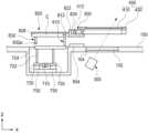
도 2는, 도 1의 레이저 가공장치의 구성 일부를 보여주는 평면도이다.
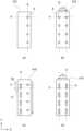
도 3a 내지 도 3d는, 도 1의 레이저 가공장치의 뷰포트보호부의 위치에 따른 뷰포트보호부 상면의 파티클적층영역을 보여주는 평면도이다.
도 4는, 도 1의 레이저 가공장치의 구성 일부를 보여주는 단면도이다.
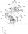
도 5a 내지 도 5b는, 도 1의 레이저 가공장치의 구성 일부의 동작을 설명하는 사시도이다.
도 6은, 도 1의 레이저 가공장치의 구성 일부를 보여주는 사시도이다.
도 7a 내지 도 7b는, 본 발명의 다른 일 실시예에 따른 레이저 가공장치의 구성 일부의 동작을 설명하는 사시도이다.
도 8a 내지 도 8b는, 본 발명의 또 다른 일 실시예에 따른 레이저 가공장치의 구성 일부의 동작을 설명하는 사시도이다.1 is a perspective view showing a laser processing device according to the present invention.
FIG. 2 is a plan view showing part of the configuration of the laser processing device of FIG. 1.
FIGS. 3A to 3D are plan views showing the particle stacking area on the upper surface of the viewport protection unit according to the position of the viewport protection unit of the laser processing device of FIG. 1.
FIG. 4 is a cross-sectional view showing part of the configuration of the laser processing device of FIG. 1.
5A to 5B are perspective views explaining the operation of some components of the laser processing device in FIG. 1.
FIG. 6 is a perspective view showing part of the configuration of the laser processing device of FIG. 1.
7A to 7B are perspective views illustrating the operation of some components of a laser processing device according to another embodiment of the present invention.
8A to 8B are perspective views illustrating the operation of some components of a laser processing device according to another embodiment of the present invention.
이하 본 발명에 따른 레이저 가공장치에 관하여 첨부된 도면을 참조하여 설명하면 다음과 같다.Hereinafter, the laser processing device according to the present invention will be described with reference to the attached drawings.
본 발명에 따른 레이저 가공장치는, 도 1 내지 도 8b에 도시된 바와 같이, 레이저를 이용하는 기판처리를 위한 처리공간(S)이 형성되는 챔버(100)와; 기판(10)의 처리면이 하방을 향하도록 기판(10)을 지지하며 상기 처리공간(S)에 상기 챔버(100)의 길이방향(이하, 제1방향)을 따라 선형이동 가능하게 설치되는 캐리어(200)와; 상기 챔버(100) 외부에 설치되며, 상기 챔버(100) 하측에 구비되는 뷰포트(102)를 통해 상기 캐리어(200)에 의해 이송되는 기판(10)의 처리면에 레이저광을 조사하는 레이저모듈(300)과; 상기 처리공간(S) 내의 파티클에 의해 상기 뷰포트(102)가 오염되는 것을 방지하기 위하여 상기 뷰포트(102) 상측에 간격을 두고 설치되는 뷰포트보호부(400)와; 상기 뷰포트보호부(400)를 지지하며 상기 뷰포트보호부(400)가 상기 제1방향에 수직한 상기 챔버(100)의 폭방향(이하, 제2방향)을 따라 이동가능하게 설치되는 지지프레임부(500)와; 상기 챔버(100) 내부에 설치되며, 상기 지지프레임부(500)를 상기 제1방향을 따라 이동시키기 위한 제1구동부(600)와; 상기 챔버(100) 내부에 설치되며, 상기 뷰포트보호부(400)를 상기 지지프레임부(500)에 대해 상기 제2방향을 따라 상대이동시키기 위한 제2구동부(700)를 포함한다.As shown in FIGS. 1 to 8B, the laser processing device according to the present invention includes a
여기서 기판처리의 대상인 기판(10)은, 식각, 증착 등 기판처리가 수행되는 구성으로서, 반도체 제조용기판, LCD 제조용기판, OLED 제조용기판, 태양전지 제조용기판, 투명 글라스기판 등 레이저가공을 통한 기판처리가 필요한 기판이면 어떠한 기판도 가능하다.Here, the
특히, 상기 기판(10)은, OLED 제조용기판으로서, 캐소드 전극과 보조전극을 연결함으로써, 캐소드 전극의 저항을 낮추기 위해 레이저를 이용하여 접촉홀이 형성되도록 기판처리될 수 있으며, 대면적 기판일 수 있다.In particular, the
상기 챔버(100)는, 레이저를 이용하는 기판처리를 위한 처리공간(S)이 형성되는 구성으로서, 다양한 구성이 가능하다.The
예를 들면, 상기 챔버(100)는, 처리공간(S)을 형성하는 챔버본체와, 챔버본체의 상단에 설치되며, 기판(10)의 회전 가능하도록, 회전반경에 대응되는 곡률로 형성되는 천정부를 포함할 수 있다.For example, the
상기 챔버(100)는, 내부가 진공상태, 대기압 상태 등 공정조건에 따라 다양한 조건일 수 있으며, 보다 바람직하게는 진공상태를 유지할 수 있다.The interior of the
상기 챔버본체는, 처리공간(S)을 형성하는 구성으로서, 다양한 구성이 가능하다.The chamber main body forms the processing space (S), and various configurations are possible.
상기 챔버본체에는, 처리면이 상방을 향한 상태로 도입되는 기판(10)이 처리면이 하방을 향하도록 플립되는 영역과, 플립된 기판(10)이 캐리어(200)에 의해 지지된 상태로 챔버본체의 길이방향을 따라 선형이동되어 레이저모듈(300)에 의해 레이저가공되는 영역이 형성될 수 있다.The chamber main body includes a region where the
상기 캐리어(200)는, 기판(10)의 처리면이 하방을 향하도록 기판(10)을 지지하며 챔버(100)의 길이방향(이하, 제1방향)을 따라 선형이동 가능하게 설치되는 구성으로 다양한 구성이 가능하다.The
여기서, 상기 제1방향은, 캐리어(200)의 선형이동방향으로, 챔버(100)의 길이방향(도면 기준, X축방향)으로 정의될 수 있다.Here, the first direction is the linear movement direction of the
이때, 본 발명은, 상기 캐리어(200)가 처리공간(S) 내에서 선형이동 가능하도록 처리공간(S)에 설치되는 주행축(미도시)을 포함할 수 있다.At this time, the present invention may include a traveling axis (not shown) installed in the processing space (S) so that the
상기 주행축은, 캐리어(200)가 선형이동 할 수 있도록 처리공간(S)에 설치되는 구성으로서, 다양한 구성이 가능하다.The traveling axis is installed in the processing space (S) so that the
예를 들면, 상기 주행축은, 한 쌍으로 설치되며 캐리어(200)가 결합하여 캐리어(200)가 안정적으로 이동하도록 할 수 있다.For example, the traveling axes may be installed as a pair and combined with the
또한, 상기 주행축은, 진공환경 및 고온환경에서의 내구성 유지를 위해, 낮은 열팽창률을 가지는 인바(INVAR) 재질로 제작될 수 있다.Additionally, the driving shaft may be made of INVAR material with a low thermal expansion coefficient to maintain durability in a vacuum environment and a high temperature environment.
한편, 상기 캐리어(200)는, X, Y, Θ방향 중 적어도 하나로 이동 가능할 수 있다.Meanwhile, the
예를 들면, 상기 캐리어(200)는, 3단 구조의 XYΘ테이블일 수 있으며, 보다 바람직하게는 2단구조의 UVW테이블일 수 있다.For example, the
한편, 이를 통해 상기 캐리어(200)는, 지지된 기판(10)의 정밀한 위치조정이 가능하며, 보다 구체적으로는 UVW테이블로써, 1단에 설치되는 1개의 선형모터와, 2단에 설치되는 2개의 선형모터를 이용하여, X, Y, Θ방향 중 적어도 하나로 이동 가능할 수 있다.Meanwhile, through this, the
이로써, 미리설치된 주행축으로 선형이동하는 캐리어(200)를 X, Y, Θ방향 중 적어도 한 방향으로 이동하여, 고정설치되는 레이저모듈(300)을 통한 기판처리를 보다 정밀한 위치에서 수행할 수 있다.As a result, the
예로서, 상기 캐리어(200)에는 기판(10)을 정전흡착하는 정전척이 구비될 수 있다.For example, the
다른 예로서, 상기 캐리어(200)에는, 진공흡착을 통해 기판(10)을 흡착하여 고정하거나 또는, 기타 물리부재를 이용하여 기판(10)을 고정 안착시킬 수 있음은 또한 물론이다.As another example, it goes without saying that the
상기 레이저모듈(300)은, 챔버(100) 외부에 설치되며, 챔버(100) 하측에 구비되는 뷰포트(102)를 통해 캐리어(200)에 의해 이송되는 기판(10)의 처리면에 레이저광을 조사하는 구성으로 다양한 구성이 가능하다.The
예를 들면, 상기 레이저모듈(300)은, 캐소드 전극의 저항을 낮추기 위하여, 캐소드 전극과 보조전극을 연결하기 위한 접촉홀을 기판(10)의 가공면에 형성하기 위한 구성일 수 있다.For example, the
한편, 기판(10)의 처리면이 상방을 향하는 페이스 업 상태에서의 가공의 경우, 가공된 부유물이 중력에 의해 기판(10)의 처리면에 재유착되는 문제가 있을 수 있는 바, 기판(10)의 처리면이 하방을 향하는 페이스다운 상태에서의 가공이 이루어 질 수 있다.On the other hand, in the case of processing in a face-up state where the processing surface of the
이를 위하여, 상기 레이저모듈(300)은, 챔버(100)의 외부 하측에 위치하여, 플립되어 하방을 향하는 기판(10) 처리면을 향해 상측으로 레이저 광을 조사할 수 있다.To this end, the
또한 상기 레이저모듈(300)은, 레이저광을 조사하는 복수의 조사부(미도시)들과, 상기 복수의 조사부들이 형성되는 레이저본체(미도시)를 포함할 수 있다.Additionally, the
상기 뷰포트보호부(400)는, 처리공간(S) 내의 파티클에 의해 뷰포트(102)가 오염되는 것을 방지하기 위하여 뷰포트(102) 상측에 간격을 두고 설치되는 구성으로 다양한 구성이 가능하다.The
상기 뷰포트(102)는, 챔버(100)의 하측에 구비되는 윈도우창으로 챔버(100) 하측에 형성되는 개구(104)에 설치될 수 있다.The
상기 뷰포트(102)를 통해 레이저모듈(300)에서 나온 레이저광이 기판(10)의 처리면에 조사될 수 있다.Laser light emitted from the
상기 뷰포트보호부(400)는, 뷰포트(102) 상측에 처리공간(S)에 발생되는 파티클이 쌓이는 것을 방지하기 위하여 뷰포트(102)의 상부에 간격을 두고 설치되는 부재로서 레이저광이 투과 가능한 글래스재질로 이루어질 수 있다.The
예로서, 상기 뷰포트보호부(400)는, 레이저광이 투과될 수 있는 보호글라스(410)와, 보호글라스(410)의 가장자리에 설치되어 보호글라스(410)를 지지하는 외곽프레임(420)을 포함할 수 있다.For example, the
상기 보호글라스(410)는, 글라스재질의 플레이트로서, 뷰포트(102)를 복개할 수 있다면 다양한 평면형상으로 이루어질 수 있으며, 설계에 따라 다양한 두께로 형성될 수 있다.The
상기 외곽프레임(420)은, 보호글라스(410)의 가장자리에 결합되어 보호글라스(410)를 지지하는 프레임으로 다양한 구성이 가능하며, 강성을 가진다면 다양한 재질로 이루어질 수 있다.The
상기 지지프레임부(500)는, 뷰포트보호부(400)를 지지하며 뷰포트보호부(400)가 상기 제1방향에 수직한 상기 챔버(100)의 폭방향(이하, 제2방향)을 따라 이동가능하게 설치되는 구성으로 다양한 구성이 가능하다.The
여기서, 상기 제2방향은, 뷰포트보호부(400)가 지지프레임부(500)에 대해 선형이동되는 방향으로, 제1방향(캐리어(200)의 선형이동방향)에 수직한 챔버(100)의 폭방향으로 정의될 수 있다.Here, the second direction is the direction in which the
상기 지지프레임부(500)는, 뷰포트보호부(400)를 지지하며 뷰포트보호부(400)가 지지프레임부(500)에 대해 제2방향을 따라 상대선형이동가능하게 설치될 수 있다면, 다양한 형상 및 재질로 이루어질 수 있다.The
상기 제1구동부(600)은, 챔버(100) 내부에 설치되며, 지지프레임부(500)를 제1방향을 따라 이동시키기 위한 구동부로서 다양한 구성이 가능하다.The
예로서, 상기 제1구동부(600)는, 챔버(100) 내에 제1방향을 따라 설치되며 외주면에 나사산이 형성되는 제1구동샤프트부(610)와, 제1구동샤프트부(610)가 회전가능하게 삽입되어 제1구동샤프트부(610)의 회전에 따라 제1방향으로 선형이동하며 지지프레임부(500)에 결합되는 제1이동블록과, 제1이동블록의 선형이동을 가이드하는 제1이동블록가이드부(620)를 포함할 수 있다.For example, the
상기 제1구동샤프트부(610)는, 챔버(100) 내에 제1방향을 따라 설치되며 외주면에 나사산이 형성되는 스크류축으로서 다양한 구성이 가능하다.The first
상기 제1구동샤프트부(610)는, 도 2에 도시된 바와 같이, 챔버(100)의 양측면에 한 쌍으로 설치될 수 있다.As shown in FIG. 2, the first
상기 제1구동샤프트부(610)는, 일단에서 회전구동부(612)와 결합되어 회전구동부(612)의 회전구동에 의해 회전될 수 있다.The first
상기 제1이동블록은, 제1구동샤프트부(610)가 회전가능하게 삽입되어 제1구동샤프트부(610)의 회전에 따라 제1방향으로 선형이동되는 구성으로, 볼스크류 또는 리드스크류의 암나사부재에 대응될 수 있다.The first moving block is a configuration in which the first
상기 제1이동블록은 지지프레임부(500)에 결합됨으로써 제1이동블록과 함께 지지프레임부(500)가 제1방향(도면기준 X축방향)을 따라 선형이동될 수 있다.The first movable block is coupled to the
이때, 상기 뷰포트보호부(400)는, 지지프레임부(500)에 결합되므로 지지프레임부(500)와 함께 제1방향(도면기준 X축방향)을 따라 선형이동될 수 있다.At this time, since the
상기 제1이동블록가이드부(620)는, 제1이동블록의 선형이동을 가이드하는 리니어가이드로서 다양한 구성이 가능하다.The first moving
상기 제1이동블록가이드부(620) 또한 제1구동샤프트부(610)에 대응되어 한 쌍으로 설치될 수 있음은 물론이다.Of course, the first moving
상술한 제1구동부(600)의 경우, 볼스크류모터 또는 리드스크류모터 방식으로 지지프레임부(500)를 직접구동할 수 있고, 그에 따라 지지프레임부(500)가 챔버(100)의 길이방향(제1방향)을 따라 챔버(100) 내의 모든영역에서 선형이동될 수 있다.In the case of the above-described first driving
상기 제2구동부(700)는, 챔버(100) 내부에 설치되며, 뷰포트보호부(400)를 지지프레임부(500)에 대해 제2방향을 따라 상대이동시키기 위한 구성으로 다양한 구성이 가능하다.The
상기 제2구동부(700)는, 챔버(100)의 하측에 제2방향을 따라 설치되며 외주면에 나사산이 형성되는 제2구동샤프트부(710)와, 제2구동샤프트부(710)가 회전가능하게 삽입되어 제2구동샤프트부(710)의 회전에 따라 제2방향으로 선형이동되는 제2이동블록(720)을 포함할 수 있다.The
상기 제2구동샤프트부(710)는, 도 2 및 도 4에 도시된 바와 같이, 챔버(100)의 하측에 제2방향을 따라 설치되며 외주면에 나사산이 형성되는 스크류축으로서 다양한 구성이 가능하다.As shown in FIGS. 2 and 4, the second
상기 제2구동샤프트부(710)는, 일단에서 회전구동부(미도시)와 결합되어 회전구동부(미도시)의 회전구동에 의해 회전될 수 있다.The second
상기 제2이동블록(720)은, 제2구동샤프트부(710)가 회전가능하게 삽입되어 제2구동샤프트부(710)의 회전에 따라 제2방향으로 선형이동되는 구성으로, 볼스크류 또는 리드스크류의 암나사부재에 대응될 수 있다.The second moving
이때, 상기 제2구동부(700)는, 상기 제2이동블록(720)의 제2방향 선형이동을 가이드하는 제2이동블록가이드부(730)을 포함할 수 있다.At this time, the
상기 제2이동블록가이드부(730)는, 제2이동블록(720)의 제2방향 선형이동을 가이드하는 리니어가이드로서 다양한 구성이 가능하다.The second moving
한편, 상기 제2구동샤프트부(710) 및 제2이동블록(720)은, 챔버(100) 내의 공간활용을 위하여, 도 4에 도시된 바와 같이, 챔버(100) 하측에 함몰되어 형성되는 공간에 설치될 수 있다.Meanwhile, the second
여기서, 상기 레이저 가공장치는, 제2구동부(700)가 처리공간(S)에 노출되는 것을 방지하기 위하여 커버부(미도시)를 추가로 포함할 수 있다.Here, the laser processing apparatus may additionally include a cover part (not shown) to prevent the
상기 커버부(미도시)는, 제2구동부(700) 특히 제2구동샤프트부(710), 제2이동블록(720), 또는 제2구동사프트부(710)의 회전을 구동하는 회전구동부(미도시)가 처리공간(S)에 그대로 노출되는 것을 방지하기 위한 커버부재로써 다양한 구성이 가능하다.The cover part (not shown) is a
한편, 상기 레이저 가공장치는, 지지프레임부(500)가 제2구동부(700)를 향해 접근함에 따라 제2구동부(700)의 구동력이 뷰포트보호부(400)로 전달되도록 제2이동블록(720)과 뷰포트보호부(400)를 결합시키며, 지지프레임부(500)가 제2구동부(700)에서 멀어짐에 따라 제2이동블록(720)과 뷰포트보호부(400)를 결합을 해제시키는 도킹부(800)를 추가로 포함할 수 있다.Meanwhile, the laser processing device uses a second moving
상기 도킹부(800)는, 뷰포트보호부(400)가 제2방향 선형이동이 필요한 영역에 진입하여 제2구동부(700)에 근접하였을 때만 뷰포트보호부(400)가 제2구동부(700)와 결합되어 제2구동부(700)로부터 구동력은 전달받을 수 있도록 하는 구성으로 다양한 구성이 가능하다.The
예로서, 상기 도킹부(800)는, 상기 제2이동블록(720)에 결합되는 제1도킹부재(810)와, 상기 외곽프레임(420)에 결합되어 상기 지지프레임부(500)가 상기 제2구동부(700)를 향해 접근함에 따라 상기 제1도킹부재(810)와 결합되는 제2도킹부재(820)를 포함할 수 있다.For example, the
이때, 상기 도킹부(800)는, 제1도킹부재(810)와 제2도킹부재(820)의 결합시 제1도킹부재(810)가 외곽프레임(420)의 제1방향이동을 제한하지 않도록 구성됨이 바람직하다.At this time, the
즉, 상기 제1도킹부재(810) 및 상기 제2도킹부재(820)는 상호 결합 시 제1방향에 대해 상대이동가능하게 결합될 수 있다.That is, when the
제1도킹부재(810)와 제2도킹부재(820) 결합 시 제1도킹부재(810)와 제2도킹부재(820)가 제1방향에 대해 상대이동 되는 바 상대이동시 제1도킹부재(810)와 제2도킹부재(820) 사이의 마찰을 고려하여, 제1도킹부재(810) 및 상기 제2도킹부재(820) 중 적어도 하나는, 상기 제1도킹부재(810) 및 상기 제2도킹부재(820) 결합 시 상호 밀착되어 회전하는 롤러부재(812, 823)를 포함할 수 있다.When the
제1실시예에서, 상기 제1도킹부재(810)는 도 4 내지 도 5b에 도시된 바와 같이, 한 쌍으로 구비되어 상기 제2방향으로 이격배치될 수 있다.In the first embodiment, the
이때, 상기 제2도킹부재(820)는 제2구동부(700)를 향해 접근함에 따라, 상기 한 쌍의 제1도킹부재(810) 사이로 진입하여 한 쌍의 제1도킹부재(810)와 결합될 수 있다.At this time, as the
상기 한 쌍의 제1도킹부재(810)는, 제2이동블록(720)에 직/간접적으로 결합되며 서로 제2방향으로 이격 배치되는 구성으로, 도 5a 및 도 5b에 도시된 바와 같이, 상방으로 연장형성되는 핀부재일 수 있다.The pair of
이때, 상기 제1도킹부재(810)는, 한 쌍의 제1도킹부재(810) 사이로 진입되는 제2도킹부재(820)와 밀착되어 회전하는 제1롤러부재(812)를 포함할 수 있다.At this time, the
상기 제1롤러부재(812)는, 제2도킹부재(810)의 상부끝단에 구비될 수 있다.The
상기 한 쌍의 제1도킹부재(810), 특히 한 쌍의 제1롤러부재(812)는, 사이 간격으로 진입한 제2도킹부재(820)가 제2방향으로 구속되어 움직이지 않도록 제2도킹부재(820)의 제2방향 폭과 대응되는 거리만큼 이격되어 배치됨이 바람직하다.The pair of
상기 한 쌍의 제1도킹부재(810)는, 복수의 연결부재(722, 724)들을 통해 제2이동블록(720)과 결합될 수 있고, 그에 따라 제2이동블록(720)과 함께 제2방향을 따라 선형이동될 수 있다.The pair of
상기 제2도킹부재(820)는, 외곽프레임(420)에 결합되어 제2구동부(700)를 향해 연장형성되며 지지프레임부(500)가 제2구동부(700)를 향해 접근함에 따라 한 쌍의 도킹부재(810) 사이로 진입하는 구성으로 다양한 구성이 가능하다.The
상기 제2도킹부재(820)는, 외곽프레임(420)에 직/간접적으로 결합되며, 도 5a 및 도 5b에 도시된 바와 같이, 평면 상 제2구동부(700)를 향해 연장형성되는 스틱형부재일 수 있다.The
상기 제2도킹부재(820)의 양측면에는 한 쌍의 제1도킹부재(810) 사이로 진입시 한 쌍의 제1도킹부재(810)와 밀착되는 한 쌍의 밀착면(C)이 형성될 수 있다.On both sides of the
상기 제2도킹부재(820)에는 밀착면(C) 형성을 위한 단차(826)가 형성될 수 있다.A
한편, 상기 제2도킹부재(820)는, 결합부재(822)를 통해 외곽프레임(420)의 일측에 고정될 수 있다.Meanwhile, the
상기 결합부재(822)는, 제2도킹부재(820)와 외곽프레임(420)을 결합시키는 구성으로 다양한 구성이 가능하다.The
또한, 상기 결합부재(822)는, 외곽프레임(420)과 결합됨과 동시에, 지지프레임부(500)의 일측에 제2방향을 따라 설치되는 가이드레일(512)에 이동가능하게 결합되는 이동블록(824)에 결합될 수 있다.In addition, the
이를 통해, 제2도킹부재(820)의 제2방향 선형이동에 따라 외곽프레임도(420)도 함께 제2방향으로 선형이동될 수 있으며, 이러한 제2방향 선형이동은 지지프레임부(500)에 설치되는 가이드레일(512)에 의해 가이드될 수 있다.Through this, the
상술한 구성에 따라, 상기 뷰포트보호부(400)는, 제2도킹부재(820)가 한 쌍의 제1도킹부재(810) 사이에 진입되는 영역에서만 제2구동부(700)에 의해 제2방향으로 선형이동될 수 있으며, 제2도킹부재(820)가 한 쌍의 제1도킹부재(810) 사이서 벗어나는 영역에서는 제2구동부(700)를 구동한다고 하더라도 뷰포트보호부(400)는 제2방향을 따라 선형이동될 수 없다.According to the above-described configuration, the
제2실시예에서, 상기 제2도킹부재(820)는 도 7a 내지 도 7b에 도시된 바와 같이, 한 쌍으로 구비되어 상기 제2방향으로 이격배치될 수 있다.In the second embodiment, the
이때, 상기 제1도킹부재(810)는 상기 제2도킹부재(820)가 상기 제2구동부(700)를 향해 접근함에 따라, 상기 한 쌍의 제2도킹부재(820) 사이로 진입하여 상기 한 쌍의 제2도킹부재(820)와 결합될 수 있다.At this time, as the
제2실시예의 경우, 제1실시예와 반대로 제1도킹부재(810)가 한 쌍의 제2도킹부재(820) 사이로 진입하여 제1도킹부재(810)와 제2도킹부재(820)가 결합된다는 점을 제외하고는 제1실시예와 동일하거나 유사하게 구성될 수 있는바, 제1실시예와의 차이점을 중심으로 제2실시예를 설명한다.In the case of the second embodiment, contrary to the first embodiment, the
제2실시예에서, 상기 한 쌍의 제2도킹부재(820)는, 외곽프레임(410)에 직간접적으로 결합되며 서로 제2방향으로 이격 배치되는 구성으로, 도 7a 내지 도 7b에 도시된 바와 같이, 하방으로 연장형성되는 핀부재일 수 있다.In the second embodiment, the pair of
이때, 상기 제2도킹부재(820)는, 결합부재(822)의 끝단에 하방연장되는 핀부재(821)와, 상기 핀부재(821)의 끝단에 설치되어 한 쌍의 제2도킹부재(820) 사이로 진입한 제1도킹부재(810)에 밀착되어 회전하는 제2롤러부재(823)를 포함할 수 있다.At this time, the
한 쌍의 제2롤러부재(823)는, 수직방향(Z축방향)을 회전 축으로 회전가능한 롤러로서, 사이 간격으로 진입한 제1도킹부재(810)에 의해 제2방향으로 구속되어 움직이지 않도록 제1도킹부재(810)의 제2방향 폭과 대응되는 거리만큼 이격되어 배치됨이 바람직하다.The pair of
상기 제1도킹부재(810)는, 복수의 연결부재(722, 724)들을 통해 제2이동블록(720)과 결합될 수 있고, 그에 따라 제2이동블록(720)과 함께 제2방향을 따라 선형이동될 수 있다.The
상기 제1도킹부재(810)에는 한 쌍의 제2롤러부재(823)와 각각 밀착되기 위해 서로 한 쌍의 제2롤러부재(823) 사이의 간격만큼 이격되며 대향하는 한 쌍의 밀착면(C)이 형성될 수 있다.The
제3실시예에서, 상기 제2도킹부재(820)는 도 8a 내지 도 8b에 도시된 바와 같이, 제2방향으로 이격배치되어 서로 대향하며 제1방향을 따라 연장형성되는 한 쌍의 도킹플레이트(829)를 구비할 수 있다.In the third embodiment, the
이때, 상기 제1도킹부재(810)는 제2도킹부재(820)가 상기 제2구동부(700)를 향해 접근함에 따라, 상기 한 쌍의 도킹플레이트(829) 사이로 진입하여 제2도킹부재(820)와 결합될 수 있다.At this time, as the
이하, 상술한 제1실시예 및 제2실시예와의 차이점을 중심으로 제3실시예를 자세히 설명한다.Hereinafter, the third embodiment will be described in detail, focusing on the differences from the first and second embodiments described above.
상기 한 쌍의 도킹플레이트(829)는 제2도킹부재(820)의 양측면이 절곡되어 하방으로 연장되는 날개를 형성할 수 있다.The pair of
또한 상기 한 쌍의 도킹플레이트(829)는, 외곽프레임(420)에 직/간접적으로 결합되며 제2구동부(700)를 향해 제1방향을 따라 연장형성될 수 있다.Additionally, the pair of
또한, 상기 한 쌍의 도킹플레이트(829)의 서로 대향하는 한 쌍의 면은 제1도킹부재(810)가 밀착되는 밀착면(C)을 형성할 수 있다.Additionally, a pair of opposing surfaces of the pair of
상기 제1도킹부재(810)는, 제2이동블록(720)에 직/간접적으로 결합되며 도 8a 및 도 8b에 도시된 바와 같이, 상방으로 연장형성되는 핀부재일 수 있다.The
예로서, 상기 제1도킹부재(810)는, 한 쌍의 도킹플레이트(829)의 밀착면(C)에 각각 밀착되어 회전하는 한 쌍의 제1롤러부재(812)를 포함할 수 있다.For example, the
구체적으로, 상기 제1도킹부재(810)는, 제1구동부(700)의 연결부재(724)에 결합되며 상방으로 연장되는 연장핀부재(814)와, 연장핑부재(814)에 결합되며 한 쌍의 제1롤러부재(812)가 설치되는 롤러설치부재(816)를 포함할 수 있다.Specifically, the
상기 연장핀부재(814) 및 롤러설치부재(816)는, 한 쌍의 제1롤러부재(812)가 한 쌍의 도킹플레이트(829) 사이로 진입할 수 있다면 다양한 형상 및 구조로 구현될 수 있음은 물론이다.The
상기 한 쌍의 제1롤러부재(812)는, 수직방향(Z축방향)을 회전 축으로 회전가능한 롤러로서, 한 쌍의 도킹플레이트(829)에 각각 밀착되어 회전하기 위하여 제2방향을 따라 배치되며, 한 쌍의 도킹플레이트(829) 사이의 간격에 대응되는 간격만큼 이격되어 설치될 수 있다.The pair of
한편, 상기 도킹부(800)는, 지지프레임부(500)가 제2구동부(700)를 향해 접근할 때, 제1도킹부재(810)와 제2도킹부재(820)가 결합되도록 제2도킹부재(820)의 제2방향 위치를 조정하는 도킹위치조정부(830)를 추가로 포함할 수 있다.Meanwhile, the
상기 도킹위치조정부(830)를 통해 제2도킹부재(820)가 정위치에서 제1도킹부재(810)와 간섭없이 부드럽게 결합될 수 있다.Through the docking
상기 도킹위치조정부(830)는, 상기 제2도킹부재(820)의 끝단 저면에 결합되어 하방으로 연장되는 위치조정용바(832)와, 상기 챔버(100) 내에 설치되어 상기 위치조정용바(832)를 상기 제1도킹부재(810)를 향해 가이드하는 도킹위치가이드플레이트(834)를 포함할 수 있다.The docking
구체적으로, 제1실시예의 경우, 상기 도킹위치조정부(830)는, 도 5a 내지 도 5b에 도시된 바와 같이, 제2도킹부재(820)의 끝단 저면에 결합되어 하방으로 연장되는 위치조정용바(832)와, 챔버(100) 내에 설치되어 상기 위치조정용바(832)를 한 쌍의 제1도킹부재(810) 사이로 가이드하는 도킹위치가이드플레이트(834)를 포함할 수 있다.Specifically, in the case of the first embodiment, the docking
상기 위치조정용바(832)는, 제2도킹부재(820)의 끝단 저면에 하방으로 연장되는 핀형상부재일 수 있다.The
상기 위치조정용바(832)는, 한 쌍의 제1도킹부재(810)와 간섭되지 않는 위치(예로서, 제2도킹부재(820)와 제2방향 기준 동일한 위치)에 위치되며, 제2도킹부재(820)의 도킹 시 제2도킹부재(820)가 안정적인 도킹이 가능한 위치에 위치되도록 보조하는 구성으로 다양한 구성이 가능하다.The
상기 위치조정용바(832)의 끝단에는 제2도킹부재(820)의 이동에 따라 후술하는 도킹위치가이드플레이트(834)와 밀착회전되기 위하여 수직방향(Z축방향)을 회전 축으로 회전가능한 롤러(832a)가 구비될 수 있다.At the end of the
상기 도킹위치가이드플레이트(834)는, 제2도킹부재(820)가 한 쌍의 제1도킹부재(810) 사이로 안정적으로 진입되도록, 위치조정용바(832)의 제2방향 위치를 가이드하는 구성으로 다양한 구성이 가능하다.The docking
상기 도킹위치가이드플레이트(834)는, 위치조정용바(832)를 한 쌍의 제2도킹부재(820) 사이로 가이드하는 가이드경로를 형성할 수 있다.The docking
상기 도킹위치가이드플레이트(834)는, 한 쌍의 제1도킹부재(810)를 향하는 방향으로 갈수록 폭이 좁아지며 끝단이 한 쌍의 제1도킹부재(810) 사이를 향하도록 가이드경로를 형성할 수 있다면 다양한 형상이 가능하다.The docking
상기 지지프레임부(500)가 제2구동부(700)를 향해 접근함에 따라 위치조정용바(832)가 도킹위치가이드플레이트(834)의 가이드경로를 따라 위치조정되어 제2도킹부재(820)가 한 쌍의 제1도킹부재(810) 사이로 가이드되며 그에 따라 제2도킹부재(820)가 한 쌍의 제1도킹부재(810) 사이로 안정적으로 진입될 수 있다.As the
제2실시예의 경우, 도 7a 내지 도 7b에 도시된 바와 같이, 한 쌍의 제2도킹부재(820)가 제1실시예의 위치조정용바(823)의 기능을 함께 수행하도록 구성될 수 있다. 이하, 제1실시예와의 차이점을 중심으로 제2실시예에서의 도킹위치조정부(830)를 설명한다.In the case of the second embodiment, as shown in FIGS. 7A and 7B, a pair of
제2실시예의 경우, 도킹위치조정부(830)는, 별도의 위치조정용바(832) 없이 도킹위치가이드플레이트(834) 만으로도 제2도킹부재(820)의 제2방향 위치를 조정할 수 있다.In the case of the second embodiment, the docking
즉, 제2실시예에서, 도킹위치가이드플레이트(834)는, 한 쌍의 제2도킹부재(820)가 이동하는 가이드경로를 제공하여 한 쌍의 제2도킹부재(820)가 제1도킹부재(810)를 향해 가이드되도록 구성될 수 있다.That is, in the second embodiment, the docking
상기 지지프레임부(500)가 제2구동부(700)를 향해 접근함에 따라 한 쌍의 제2도킹부재(820)가 도킹위치가이드플레이트(834)의 가이드경로를 따라 제1도킹부재(810)를 향해 가이드되며 그에 따라 제1도킹부재(820)가 한 쌍의 제2도킹부재(820) 사이로 안정적으로 진입될 수 있다.As the
제3실시예의 경우, 도 8a 내지 도 8b에 도시된 바와 같이, 상기 도킹위치조정부(830)는, 제2도킹부재(820)의 끝단 저면에 결합되어 하방으로 연장되는 위치조정용바(832)와, 챔버(100) 내에 설치되어 위치조정용바(832)의 제2방향 위치를 가이드하는 도킹위치가이드플레이트(834)를 포함할 수 있다.In the third embodiment, as shown in FIGS. 8A to 8B, the docking
이하, 제1실시예 및 제2실시예와의 차이점을 중심으로 제3실시예에서의 도킹위치조정부(830)를 설명한다.Hereinafter, the docking
제3실시예에서, 한 쌍의 도킹플레이트(829) 사이로 제1도킹부재(810)가 진입되도록, 제1도킹부재(810)와 간섭되지 않는 위치에 위치조정용바(832)가 설치될 수 있다.In the third embodiment, the
예로서, 위치조정용바(832)는, 한 쌍의 도킹플레이트(829) 저면 각각에 한 쌍으로 설치될 수 있다.As an example, the
상기 지지프레임부(500)가 제2구동부(700)를 향해 접근함에 따라 한 쌍의 위치조정용바(832)가 도킹위치가이드플레이트(834)의 가이드경로를 따라 위치조정되어 제2도킹부재(820)가 제1도킹부재(810)를 향해 가이드되며 그에 따라 제1도킹부재(810)가 한 쌍의 도킹플레이트(829) 사이로 안정적으로 진입될 수 있다.As the
한편, 상기 레이저 가공장치는, 도 1에 도시된 바와 같이, 챔버(100)의 일측에 결합되는 뷰포트보호부(400)에 대한 교체를 위한 뷰포트보호부교체모듈(900)를 추가로 포함할 수 있다.Meanwhile, as shown in FIG. 1, the laser processing device may additionally include a viewport protection
상기 뷰포트보호부교체모듈(900)은, 뷰포트보호부(400)들을 수용하며, 뷰포트보호부교체모듈(900)과 챔버(100) 사이에 설치되는 게이트(G)를 통해 챔버(100)로부터 교체가 필요한 뷰포트보호부(400)를 전달받고 새로운 뷰포트보호부(400)를 챔버(100)로 전달함으로써, 뷰포트보호부(400)의 교체를 가능하게 하는 구성으로 다양한 구성이 가능하다.The viewport protection
그런데, 상기 뷰포트보호부교체모듈(900)을 통한 뷰포트보호부(400)의 교체를 원활히 수행하기 위해서는 교체시 뷰포트보호부(400)가 챔버(100) 내 정위치에 센터링될 필요가 있다.However, in order to smoothly replace the
이를 위해, 뷰포트보호부(400) 교체 시 센터유지를 위해 뷰포트보호부(400)를 볼플런저(ball plunger)를 통해 고정할 수 있으나, 뷰포트보호부(400)가 볼플런저를 벗어나는 경우가 발생할 수 있다.To this end, when replacing the
본 발명은 뷰포트보호부(400) 교체 시 뷰포트보호부(400)가 볼플런저를 벗어나는 경우에도 뷰포트보호부(400)의 센터를 유지하기 위하여, 제1도킹부재(810)와 제2도킹부재(820) 사이의 결합이 해제된 상태에서 뷰포트보호부(400)가 제2방향 기준 센터에 위치되도록 위치조정용바(832)의 이동을 가이드하는 센터가이드플레이트(850)를 추가로 포함할 수 있다.The present invention includes a
상기 센터가이드플레이트(850)는, 제1도킹부재(810)와 제2도킹부재(820) 사이의 결합이 해제된 상태에서 뷰포트보호부(400)가 제2방향 기준 센터에 위치되도록 위치조정용바(832)의 이동을 가이드하는 가이드경로를 형성하는 구성으로 다양한 구성이 가능하다.The
예로서, 상기 센터가이드플레이트(850)는 도 6에 도시된 바와 같이, 위치조정용바(832)가 경로(L)를 따라 이동함에 따라 제2방향 기준 센터를 향해 수렴할 수 있도록 하며 양방향 모두 적용가능하도록 제2방향 기준 센터에 가장 폭이 좁은 중앙부경로가 형성되며 양측으로 멀어질수록 폭이 넓어지는 호리병형상의 가이드경로를 형성하는 한 쌍의 센터가이드플레이트부재(852, 854)를 포함할 수 있다.For example, as shown in FIG. 6, the
상기 센터가이드플레이트(850)는, 제2도킹부재(820)가 한 쌍의 제1도킹부재(810) 사이에서 벗어난 영역, 보다 구체적으로는, 뷰포트보호부재(400)의 교체가 이루어지는 영역의 챔버(100) 하측에 설치될 수 있다.The
이때, 상기 위치조정용바(832)의 끝단에 구비되는 롤러(832a)는 제2도킹부재(820)가 센터로 가이드되도록 센터가이드플레이트(850)에 밀착된 상태로 회전될 수 있다.At this time, the
한편, 상기 레이저 가공장치는, 뷰포트보호부(400)를 통한 레이저광의 투과율이 저하되지 않도록, 뷰포트보호부(400)의 제1방향 및 제2방향 중 적어도 하나의 위치를 조정하도록 제1구동부(600) 및 제2구동부(700) 중 적어도 하나를 제어하는 제어부를 추가로 포함할 수 있다.Meanwhile, the laser processing device includes a first driving unit ( 600) and a control unit that controls at least one of the
이하, 레이저 가공장치, 특히 뷰포트보호부(400)의 제1방향 및 제2방향 이동과 관련하여 제어부의 동작을 자세히 설명한다.Hereinafter, the operation of the control unit will be described in detail in relation to the movement of the laser processing device, particularly the
상기 챔버(100)의 일측을 통해 기판(10)이 도입되면 처리면이 하방을 향하도록 플립된 후 캐리어(200)에 의해 챔버(100)의 타측을 향해 제1방향을 따라 선형이동될 수 있다.When the
상기 제어부는, 제1방향을 따라 선형이동되는 기판(10)의 처리면에 레이저모듈(300)에서 나온 레이저광을 통해 기판처리가 수행됨에 따라 뷰포트(102)가 오염되는 것을 방지하기 위하여, 뷰포트보호부(400)의 제1방향 위치를 조정하여 뷰포트(102) 직상부에 위치되도록 제1구동부(600)를 제어할 수 있다.The control unit operates the
이때, 상기 뷰포트보호부(400)는, 도 3a와 같이 위치될 수 있고, 기판처리가 수행됨에 따라 보호글라스(410) 상 라인 g를 따라 배치되는 A영역(파티클적층영역)에 파티클이 적층될 수 있다.At this time, the
기판처리가 지속됨에 따라 A영역에 파티클이 점차 쌓이면서 A영역을 투과하는 레이저광의 파워가 점차 떨어지게 될 수 있다.As substrate processing continues, particles gradually accumulate in area A, and the power of the laser light passing through area A may gradually decrease.
이때, 상기 제어부는, 보호글라스(410)를 통과하는 레이저광의 파워가 미리 설정된 기준값 이하가 되지 않도록, 뷰포트보호부(400)를 제1방향 또는 제2방향 중 어느 하나의 방향으로 선형이동시킬 수 있다.At this time, the control unit may linearly move the
예로서, 상기 제어부는, 도 3a와 같이 뷰포트보호부(400)를 위치시킨 상태에서 기판처리를 수행하다가, A영역에 파티클이 과도하게 적층되면, 도 3b와 같이, 제1구동부(600)를 통해 지지프레임부(500)를 제1방향으로 선형이동시켜 뷰포트보호부(400)의 제1방향 위치를 +△X 만큼 조정할 수 있다.For example, while performing substrate processing with the
이를 통해, 라인 g를 따라 배치되는 A영역은 보호글라스(410)의 미사용영역에 재대응될 수 있고, 보호글라스(410)에 대한 교체 없이 보호글라스(410)를 다시 활용하여 기판처리를 수행할 수 있다.Through this, area A arranged along line g can be re-corresponded to the unused area of the
기판처리가 지속됨에 따라 도 3b의 A영역 또한 파티클이 점차 쌓이면서 A영역을 투과하는 레이저광의 파워가 점차 떨어지게 될 수 있다.As substrate processing continues, particles gradually accumulate in area A of FIG. 3B, and the power of the laser light passing through area A may gradually decrease.
이때, 상기 제어부는, 보호글라스(410)를 통과하는 레이저광의 파워가 미리 설정된 기준값 이하가 되지 않도록, 뷰포트보호부(400)를 다시 제1방향 또는 제2방향 중 어느 하나의 방향으로 선형이동시킬 수 있다.At this time, the control unit linearly moves the
예로서, 상기 제어부는, 도 3b와 같이 뷰포트보호부(400)를 위치시킨 상태에서 기판처리를 수행하다가, A영역에 파티클이 과도하게 적층되면, 도 3c와 같이, 제2구동부(700)를 통해 지지프레임부(500)에 대해 뷰포트보호부(400)를 제2방향으로 선형이동시켜 뷰포트보호부(400)의 제2방향 위치를 +△Y 만큼 조정할 수 있다.For example, the control unit performs substrate processing with the
이를 통해, 라인 p 상에 위치하는 A영역이 라인 p 상으로부터 이탈하도록 조정되어 A영역은 보호글라스(410)의 미사용영역에 재대응될 수 있고, 보호글라스(410)에 대한 교체 없이 보호글라스(410)를 다시 활용하여 기판처리를 수행할 수 있다.Through this, area A located on line p is adjusted to deviate from line p, so area A can be re-corresponded to the unused area of the
기판처리가 지속됨에 따라 도 3c의 A영역 또한 파티클이 점차 쌓이면서 A영역을 투과하는 레이저광의 파워가 점차 떨어지게 될 수 있다.As substrate processing continues, particles gradually accumulate in area A of FIG. 3C, and the power of the laser light passing through area A may gradually decrease.
이때, 상기 제어부는, 보호글라스(410)를 통과하는 레이저광의 파워가 미리 설정된 기준값 이하가 되지 않도록, 뷰포트보호부(400)를 다시 제1방향 또는 제2방향 중 어느 하나의 방향으로 선형이동시킬 수 있다.At this time, the control unit linearly moves the
예로서, 상기 제어부는, 도 3c와 같이 뷰포트보호부(400)를 위치시킨 상태에서 기판처리를 수행하다가, A영역에 파티클이 과도하게 적층되면, 도 3d와 같이, 제1구동부(600)를 통해 지지프레임부(500)를 제1방향으로 선형이동시켜 뷰포트보호부(400)의 제1방향 위치를 -△X 만큼 조정할 수 있다.For example, the control unit performs substrate processing with the
이를 통해, 라인 g를 따라 배치되는 A영역은 보호글라스(410)의 미사용영역에 재대응될 수 있고, 보호글라스(410)에 대한 교체 없이 보호글라스(410)를 다시 활용하여 기판처리를 수행할 수 있다.Through this, area A arranged along line g can be re-corresponded to the unused area of the
본 발명은, 상기 제어부가 제1구동부(600) 및 제2구동부(700)를 통해 뷰포트보호부(400)의 제1방향 위치 및 제2방향 위치를 적절히 조정함에 따라 보호글라스(410)의 미사용영역을 최소화하며 보호글라스(410)를 교체없이 오랜 시간동안 활용할 수 있고, 그에 따라 뷰포트보호부(400)의 교체주기를 극대화할 수 있는 이점이 있다.In the present invention, the control unit appropriately adjusts the first and second direction positions of the
이상은 본 발명에 의해 구현될 수 있는 바람직한 실시예의 일부에 관하여 설명한 것에 불과하므로, 주지된 바와 같이 본 발명의 범위는 위의 실시예에 한정되어 해석되어서는 안 될 것이며, 위에서 설명된 본 발명의 기술적 사상과 그 근본을 함께하는 기술적 사상은 모두 본 발명의 범위에 포함된다고 할 것이다.Since the above is only a description of some of the preferred embodiments that can be implemented by the present invention, as is well known, the scope of the present invention should not be construed as limited to the above embodiments, and the scope of the present invention described above Both the technical idea and the technical idea underlying it will be said to be included in the scope of the present invention.
10: 기판100: 챔버
200: 캐리어300:레이저모듈10: substrate 100: chamber
200: Carrier 300: Laser module
Claims (15)
Translated fromKorean기판(10)의 처리면이 하방을 향하도록 기판(10)을 지지하며 상기 챔버(100)의 길이방향(이하, 제1방향)을 따라 선형이동 가능하게 설치되는 캐리어(200)와;
상기 챔버(100) 외부에 설치되며, 상기 챔버(100) 하측에 구비되는 뷰포트(102)를 통해 상기 캐리어(200)에 의해 이송되는 기판(10)의 처리면에 레이저광을 조사하는 레이저모듈(300)과;
상기 처리공간(S) 내의 파티클에 의해 상기 뷰포트(102)가 오염되는 것을 방지하기 위하여 상기 뷰포트(102) 상측에 간격을 두고 설치되는 뷰포트보호부(400)와;
상기 뷰포트보호부(400)를 지지하며 상기 뷰포트보호부(400)가 상기 제1방향에 수직한 상기 챔버(100)의 폭방향(이하, 제2방향)을 따라 이동가능하게 설치되는 지지프레임부(500)와;
상기 챔버(100) 내부에 설치되며, 상기 지지프레임부(500)를 상기 제1방향을 따라 이동시키기 위한 제1구동부(600)와;
상기 챔버(100) 내부에 설치되며, 상기 뷰포트보호부(400)를 상기 지지프레임부(500)에 대해 상기 제2방향을 따라 상대이동시키기 위한 제2구동부(700)를 포함하는 것을 특징으로 하는 레이저 가공장치.a chamber 100 in which a processing space (S) for substrate processing using a laser is formed;
a carrier 200 that supports the substrate 10 so that the processing surface of the substrate 10 faces downward and is installed to be linearly movable along the longitudinal direction (hereinafter, the first direction) of the chamber 100;
A laser module ( 300) and;
a viewport protection unit 400 installed at intervals above the viewport 102 to prevent the viewport 102 from being contaminated by particles in the processing space (S);
A support frame unit that supports the viewport protection unit 400 and is movably installed along the width direction (hereinafter, second direction) of the chamber 100, where the viewport protection unit 400 is perpendicular to the first direction. (500) and;
a first driving unit 600 installed inside the chamber 100 and configured to move the support frame unit 500 in the first direction;
It is installed inside the chamber 100, and includes a second driving unit 700 for relatively moving the viewport protection unit 400 along the second direction with respect to the support frame unit 500. Laser processing equipment.
상기 뷰포트보호부(400)는,
상기 레이저광이 투과될 수 있는 보호글라스(410)와, 상기 보호글라스(410)의 가장자리에 설치되어 상기 보호글라스(410)를 지지하는 외곽프레임(420)을 포함하는 것을 특징으로 하는 레이저 가공장치.In claim 1,
The viewport protection unit 400,
A laser processing device comprising a protective glass 410 through which the laser light can pass, and an outer frame 420 installed at an edge of the protective glass 410 to support the protective glass 410. .
상기 제1구동부(600)는,
상기 챔버(100) 내에 상기 제1방향을 따라 설치되며 외주면에 나사산이 형성되는 제1구동샤프트부(610)와, 상기 제1구동샤프트부(610)가 회전가능하게 삽입되어 상기 제1구동샤프트부(610)의 회전에 따라 상기 제1방향으로 선형이동하며 상기 지지프레임부(500)에 결합되는 제1이동블록과, 상기 제1이동블록의 선형이동을 가이드하는 제1이동블록가이드부(620)를 포함하는 것을 특징으로 하는 레이저 가공장치.In claim 1,
The first driving unit 600,
A first driving shaft part 610 is installed in the chamber 100 along the first direction and has threads formed on the outer peripheral surface, and the first driving shaft part 610 is rotatably inserted to form the first driving shaft. A first movable block that linearly moves in the first direction according to the rotation of the unit 610 and is coupled to the support frame portion 500, and a first movable block guide portion that guides the linear movement of the first movable block ( 620) A laser processing device comprising:
상기 제2구동부(700)는,
상기 챔버(100)의 하측에 상기 제2방향을 따라 설치되며 외주면에 나사산이 형성되는 제2구동샤프트부(710)와,
상기 제2구동샤프트부(710)가 회전가능하게 삽입되어 상기 제2구동샤프트부(710)의 회전에 따라 상기 제2방향으로 선형이동되는 제2이동블록(720)을 포함하는 것을 특징으로 하는 레이저 가공장치.In claim 2,
The second driving unit 700,
A second drive shaft portion 710 installed along the second direction below the chamber 100 and having threads formed on the outer peripheral surface,
The second driving shaft unit 710 is rotatably inserted and includes a second moving block 720 that linearly moves in the second direction according to the rotation of the second driving shaft unit 710. Laser processing equipment.
상기 레이저 가공장치는,
상기 지지프레임부(500)가 상기 제2구동부(700)를 향해 접근함에 따라 상기 제2구동부(700)의 구동력이 상기 뷰포트보호부(400)로 전달되도록 상기 제2이동블록(720)과 상기 뷰포트보호부(400)를 결합시키며, 상기 지지프레임부(500)가 상기 제2구동부(700)에서 멀어짐에 따라 상기 제2이동블록(720)과 상기 뷰포트보호부(400)를 결합을 해제시키는 도킹부(800)를 추가로 포함하는 것을 특징으로 하는 레이저 가공장치.In claim 4,
The laser processing device,
As the support frame unit 500 approaches the second driving unit 700, the second moving block 720 and the driving force of the second driving unit 700 are transmitted to the viewport protection unit 400. It couples the viewport protection unit 400, and as the support frame unit 500 moves away from the second driving unit 700, the second moving block 720 and the viewport protection unit 400 are disconnected. A laser processing device characterized in that it additionally includes a docking portion (800).
상기 도킹부(800)는,
상기 제2이동블록(720)에 결합되는 제1도킹부재(810)와,
상기 외곽프레임(420)에 결합되어 상기 지지프레임부(500)가 상기 제2구동부(700)를 향해 접근함에 따라 상기 제1도킹부재(810)와 결합되는 제2도킹부재(820)를 포함하는 것을 특징으로 하는 레이저 가공장치.In claim 5,
The docking unit 800,
A first docking member 810 coupled to the second moving block 720,
A second docking member 820 is coupled to the outer frame 420 and coupled to the first docking member 810 as the support frame portion 500 approaches the second driving unit 700. A laser processing device characterized in that.
상기 제1도킹부재(810) 및 상기 제2도킹부재(820)는 상기 제1방향에 대해 상대이동가능하게 결합되는 것을 특징으로 하는 레이저 가공장치.In claim 6,
The first docking member 810 and the second docking member 820 are coupled to enable relative movement in the first direction.
상기 제1도킹부재(810)는 한 쌍으로 구비되어 상기 제2방향으로 이격배치되며,
상기 제2도킹부재(820)는 상기 제2구동부(700)를 향해 접근함에 따라, 상기 한 쌍의 제1도킹부재(810) 사이로 진입하여 상기 한 쌍의 제1도킹부재(810)와 결합되는 것을 특징으로 하는 레이저 가공장치.In claim 6,
The first docking members 810 are provided as a pair and spaced apart in the second direction,
As the second docking member 820 approaches the second driving unit 700, it enters between the pair of first docking members 810 and is coupled to the pair of first docking members 810. A laser processing device characterized in that.
상기 제2도킹부재(820)는 한 쌍으로 구비되어 상기 제2방향으로 이격배치되며,
상기 제1도킹부재(810)는 상기 제2도킹부재(820)가 상기 제2구동부(700)를 향해 접근함에 따라, 상기 한 쌍의 제2도킹부재(820) 사이로 진입하여 상기 한 쌍의 제2도킹부재(820)와 결합되는 것을 특징으로 하는 레이저 가공장치.In claim 6,
The second docking members 820 are provided as a pair and spaced apart in the second direction,
As the second docking member 820 approaches the second driving unit 700, the first docking member 810 enters between the pair of second docking members 820 and connects the second docking member 810 to the second docking member 820. 2A laser processing device characterized in that it is combined with a docking member (820).
상기 제2도킹부재(820)는 상기 제2방향으로 이격배치되어 서로 대향하며 상기 제1방향을 따라 연장형성되는 한 쌍의 도킹플레이트(829)를 구비하며,
상기 제1도킹부재(810)는 상기 제2도킹부재(820)가 상기 제2구동부(700)를 향해 접근함에 따라, 상기 한 쌍의 도킹플레이트(829) 사이로 진입하여 상기 제2도킹부재(820)와 결합되는 것을 특징으로 하는 레이저 가공장치.In claim 6,
The second docking member 820 includes a pair of docking plates 829 that are spaced apart in the second direction, face each other, and extend along the first direction,
As the second docking member 820 approaches the second driving unit 700, the first docking member 810 enters between the pair of docking plates 829 and is connected to the second docking member 820. ) A laser processing device characterized in that it is combined with.
상기 도킹부(800)는,
상기 지지프레임부(500)가 상기 제2구동부(700)를 향해 접근할 때, 상기 제1도킹부재(810)와 상기 제2도킹부재(820)가 결합되도록 상기 제2도킹부재(820)의 상기 제2방향 위치를 조정하는 도킹위치조정부(830)를 추가로 포함하는 것을 특징으로 하는 레이저 가공장치.The method of any one of claims 6 to 10,
The docking unit 800,
When the support frame unit 500 approaches the second driving unit 700, the second docking member 820 is connected so that the first docking member 810 and the second docking member 820 are coupled. A laser processing device, characterized in that it additionally includes a docking position adjusting unit 830 that adjusts the second direction position.
상기 제1도킹부재(810) 및 상기 제2도킹부재(820) 중 적어도 하나는, 상기 제1도킹부재(810) 및 상기 제2도킹부재(820) 결합 시 상호 밀착되어 회전하는 롤러부재(812, 823)를 포함하는 것을 특징으로 하는 레이저 가공장치.The method of any one of claims 6 to 10,
At least one of the first docking member 810 and the second docking member 820 is a roller member 812 that rotates in close contact with each other when the first docking member 810 and the second docking member 820 are coupled. , 823). A laser processing device comprising:
상기 도킹위치조정부(830)는,
상기 제2도킹부재(820)의 끝단 저면에 결합되어 하방으로 연장되는 위치조정용바(832)와, 상기 챔버(100) 내에 설치되어 상기 위치조정용바(832)를 상기 제1도킹부재(810)를 향해 가이드하는 도킹위치가이드플레이트(834)를 포함하는 것을 특징으로 하는 레이저 가공장치.In claim 11,
The docking position adjustment unit 830,
A position adjustment bar 832 is coupled to the bottom of the end of the second docking member 820 and extends downward, and is installed in the chamber 100 to attach the position adjustment bar 832 to the first docking member 810. A laser processing device comprising a docking position guide plate 834 that guides toward.
상기 레이저 가공장치는,
상기 제1도킹부재(810)와 상기 제2도킹부재(820) 사이의 결합이 해제된 상태에서 상기 뷰포트보호부(400)가 상기 제2방향 기준 센터에 위치되도록 상기 위치조정용바(832)의 이동을 가이드하는 센터가이드플레이트(850)를 추가로 포함하는 것을 특징으로 하는 레이저 가공장치.In claim 13,
The laser processing device,
In a state in which the coupling between the first docking member 810 and the second docking member 820 is released, the position adjustment bar 832 is adjusted so that the viewport protection unit 400 is positioned at the second direction reference center. A laser processing device characterized in that it additionally includes a center guide plate 850 to guide movement.
상기 레이저 가공장치는,
상기 뷰포트보호부(400)를 통한 상기 레이저광의 투과율이 저하되지 않도록, 상기 뷰포트보호부(400)의 상기 제1방향 및 상기 제2방향 중 적어도 하나의 위치를 조정하도록 상기 제1구동부(600) 및 상기 제2구동부(700) 중 적어도 하나를 제어하는 제어부를 추가로 포함하는 것을 특징으로 하는 레이저 가공장치.The method of any one of claims 1 to 10,
The laser processing device,
The first driving unit 600 to adjust the position of at least one of the first direction and the second direction of the viewport protection unit 400 so that the transmittance of the laser light through the viewport protection unit 400 does not decrease. and a control unit that controls at least one of the second driving units (700).
Priority Applications (1)
| Application Number | Priority Date | Filing Date | Title |
|---|---|---|---|
| KR1020190077092AKR102584725B1 (en) | 2019-06-27 | 2019-06-27 | laser processing apparatus |
Applications Claiming Priority (1)
| Application Number | Priority Date | Filing Date | Title |
|---|---|---|---|
| KR1020190077092AKR102584725B1 (en) | 2019-06-27 | 2019-06-27 | laser processing apparatus |
Publications (2)
| Publication Number | Publication Date |
|---|---|
| KR20210001256A KR20210001256A (en) | 2021-01-06 |
| KR102584725B1true KR102584725B1 (en) | 2023-10-05 |
Family
ID=74128709
Family Applications (1)
| Application Number | Title | Priority Date | Filing Date |
|---|---|---|---|
| KR1020190077092AActiveKR102584725B1 (en) | 2019-06-27 | 2019-06-27 | laser processing apparatus |
Country Status (1)
| Country | Link |
|---|---|
| KR (1) | KR102584725B1 (en) |
Family Cites Families (2)
| Publication number | Priority date | Publication date | Assignee | Title |
|---|---|---|---|---|
| KR101759522B1 (en)* | 2016-01-04 | 2017-07-19 | 주식회사 에스에프에이 | Apparatus for etching glass using laser |
| KR101913579B1 (en)* | 2016-12-22 | 2018-11-01 | 삼성디스플레이 주식회사 | Apparatus for etching substrates |
- 2019
- 2019-06-27KRKR1020190077092Apatent/KR102584725B1/enactiveActive
Also Published As
| Publication number | Publication date |
|---|---|
| KR20210001256A (en) | 2021-01-06 |
Similar Documents
| Publication | Publication Date | Title |
|---|---|---|
| KR102730074B1 (en) | Transfer carrier, vapor deposition apparatus, and manufacturing apparatus of electronic device | |
| KR102712657B1 (en) | Alignment apparatus, vapor deposition apparatus, manufacturing apparatus of electronic device, and alignment method | |
| JP7037379B2 (en) | A transfer robot equipped with a thin plate-shaped substrate holding device and a holding device. | |
| JP6754266B2 (en) | Laser irradiation device, laser irradiation method, and manufacturing method of semiconductor device | |
| KR102107973B1 (en) | Apparatus and system for processing a substrate in a vacuum chamber, and method of aligning a substrate carrier with respect to a mask carrier | |
| KR20150002802A (en) | Accommodating container, shutter opening and closing unit for accommodating container, and wafer stocker using same | |
| KR101666805B1 (en) | Apparatus for rotating substrate | |
| KR20230135077A (en) | Transport apparatus, transport method, and semiconductor device manufacturing method | |
| KR102584725B1 (en) | laser processing apparatus | |
| KR101898063B1 (en) | Align module, and method for aligning substrate and mask | |
| JP2019526701A (en) | Apparatus and system for processing a substrate in a vacuum chamber and method for transporting a carrier in a vacuum chamber | |
| KR101154843B1 (en) | ES-Chuck carrier | |
| KR102512208B1 (en) | laser processing apparatus | |
| KR102584726B1 (en) | laser processing apparatus | |
| KR102153644B1 (en) | Film forming apparatus, mask frame, alignment method | |
| WO2007059347A2 (en) | Flexible magnetron including partial rolling support and centering pins | |
| KR101310096B1 (en) | Unit for supporting substrate and apparatus for treating substrate using the same | |
| KR101275604B1 (en) | Substrate supporting unit and substrate processing apparatus using the same | |
| CN112382597A (en) | Storage box conveying device | |
| KR20190110593A (en) | Holders for substrates | |
| JP2008084847A (en) | Exhaust hole processing device for display panel | |
| KR20210145641A (en) | Align apparatus of laminating sheet for ultra thin glass | |
| KR102296394B1 (en) | Apparatus for etching substrates | |
| KR101234020B1 (en) | Vacuum processing apparatus using ES-Chuck carrier | |
| KR20140021316A (en) | Substrate transfer module |
Legal Events
| Date | Code | Title | Description |
|---|---|---|---|
| PA0109 | Patent application | Patent event code:PA01091R01D Comment text:Patent Application Patent event date:20190627 | |
| PG1501 | Laying open of application | ||
| A201 | Request for examination | ||
| PA0201 | Request for examination | Patent event code:PA02012R01D Patent event date:20211214 Comment text:Request for Examination of Application Patent event code:PA02011R01I Patent event date:20190627 Comment text:Patent Application | |
| E902 | Notification of reason for refusal | ||
| PE0902 | Notice of grounds for rejection | Comment text:Notification of reason for refusal Patent event date:20230710 Patent event code:PE09021S01D | |
| E701 | Decision to grant or registration of patent right | ||
| PE0701 | Decision of registration | Patent event code:PE07011S01D Comment text:Decision to Grant Registration Patent event date:20230904 | |
| GRNT | Written decision to grant | ||
| PR0701 | Registration of establishment | Comment text:Registration of Establishment Patent event date:20230926 Patent event code:PR07011E01D | |
| PR1002 | Payment of registration fee | Payment date:20230926 End annual number:3 Start annual number:1 | |
| PG1601 | Publication of registration |