KR102583380B1 - Fast pulse electrohydraulic (EH) shock wave generator device with improved acoustic wavefront - Google Patents
Fast pulse electrohydraulic (EH) shock wave generator device with improved acoustic wavefrontDownload PDFInfo
- Publication number
- KR102583380B1 KR102583380B1KR1020197024022AKR20197024022AKR102583380B1KR 102583380 B1KR102583380 B1KR 102583380B1KR 1020197024022 AKR1020197024022 AKR 1020197024022AKR 20197024022 AKR20197024022 AKR 20197024022AKR 102583380 B1KR102583380 B1KR 102583380B1
- Authority
- KR
- South Korea
- Prior art keywords
- acoustic
- reflector
- electrodes
- depth
- acoustic waves
- Prior art date
- Legal status (The legal status is an assumption and is not a legal conclusion. Google has not performed a legal analysis and makes no representation as to the accuracy of the status listed.)
- Active
Links
Images


Classifications
- A—HUMAN NECESSITIES
- A61—MEDICAL OR VETERINARY SCIENCE; HYGIENE
- A61B—DIAGNOSIS; SURGERY; IDENTIFICATION
- A61B17/00—Surgical instruments, devices or methods
- A61B17/22—Implements for squeezing-off ulcers or the like on inner organs of the body; Implements for scraping-out cavities of body organs, e.g. bones; for invasive removal or destruction of calculus using mechanical vibrations; for removing obstructions in blood vessels, not otherwise provided for
- A61B17/225—Implements for squeezing-off ulcers or the like on inner organs of the body; Implements for scraping-out cavities of body organs, e.g. bones; for invasive removal or destruction of calculus using mechanical vibrations; for removing obstructions in blood vessels, not otherwise provided for for extracorporeal shock wave lithotripsy [ESWL], e.g. by using ultrasonic waves
- A—HUMAN NECESSITIES
- A61—MEDICAL OR VETERINARY SCIENCE; HYGIENE
- A61B—DIAGNOSIS; SURGERY; IDENTIFICATION
- A61B17/00—Surgical instruments, devices or methods
- A61B17/22—Implements for squeezing-off ulcers or the like on inner organs of the body; Implements for scraping-out cavities of body organs, e.g. bones; for invasive removal or destruction of calculus using mechanical vibrations; for removing obstructions in blood vessels, not otherwise provided for
- A61B17/22004—Implements for squeezing-off ulcers or the like on inner organs of the body; Implements for scraping-out cavities of body organs, e.g. bones; for invasive removal or destruction of calculus using mechanical vibrations; for removing obstructions in blood vessels, not otherwise provided for using mechanical vibrations, e.g. ultrasonic shock waves
- A61B17/22012—Implements for squeezing-off ulcers or the like on inner organs of the body; Implements for scraping-out cavities of body organs, e.g. bones; for invasive removal or destruction of calculus using mechanical vibrations; for removing obstructions in blood vessels, not otherwise provided for using mechanical vibrations, e.g. ultrasonic shock waves in direct contact with, or very close to, the obstruction or concrement
- A—HUMAN NECESSITIES
- A61—MEDICAL OR VETERINARY SCIENCE; HYGIENE
- A61N—ELECTROTHERAPY; MAGNETOTHERAPY; RADIATION THERAPY; ULTRASOUND THERAPY
- A61N7/00—Ultrasound therapy
- G—PHYSICS
- G10—MUSICAL INSTRUMENTS; ACOUSTICS
- G10K—SOUND-PRODUCING DEVICES; METHODS OR DEVICES FOR PROTECTING AGAINST, OR FOR DAMPING, NOISE OR OTHER ACOUSTIC WAVES IN GENERAL; ACOUSTICS NOT OTHERWISE PROVIDED FOR
- G10K11/00—Methods or devices for transmitting, conducting or directing sound in general; Methods or devices for protecting against, or for damping, noise or other acoustic waves in general
- G10K11/18—Methods or devices for transmitting, conducting or directing sound
- G10K11/20—Reflecting arrangements
- G—PHYSICS
- G10—MUSICAL INSTRUMENTS; ACOUSTICS
- G10K—SOUND-PRODUCING DEVICES; METHODS OR DEVICES FOR PROTECTING AGAINST, OR FOR DAMPING, NOISE OR OTHER ACOUSTIC WAVES IN GENERAL; ACOUSTICS NOT OTHERWISE PROVIDED FOR
- G10K11/00—Methods or devices for transmitting, conducting or directing sound in general; Methods or devices for protecting against, or for damping, noise or other acoustic waves in general
- G10K11/18—Methods or devices for transmitting, conducting or directing sound
- G10K11/26—Sound-focusing or directing, e.g. scanning
- G10K11/28—Sound-focusing or directing, e.g. scanning using reflection, e.g. parabolic reflectors
- G—PHYSICS
- G10—MUSICAL INSTRUMENTS; ACOUSTICS
- G10K—SOUND-PRODUCING DEVICES; METHODS OR DEVICES FOR PROTECTING AGAINST, OR FOR DAMPING, NOISE OR OTHER ACOUSTIC WAVES IN GENERAL; ACOUSTICS NOT OTHERWISE PROVIDED FOR
- G10K11/00—Methods or devices for transmitting, conducting or directing sound in general; Methods or devices for protecting against, or for damping, noise or other acoustic waves in general
- G10K11/18—Methods or devices for transmitting, conducting or directing sound
- G10K11/26—Sound-focusing or directing, e.g. scanning
- G10K11/35—Sound-focusing or directing, e.g. scanning using mechanical steering of transducers or their beams
- G10K11/352—Sound-focusing or directing, e.g. scanning using mechanical steering of transducers or their beams by moving the transducer
- G—PHYSICS
- G10—MUSICAL INSTRUMENTS; ACOUSTICS
- G10K—SOUND-PRODUCING DEVICES; METHODS OR DEVICES FOR PROTECTING AGAINST, OR FOR DAMPING, NOISE OR OTHER ACOUSTIC WAVES IN GENERAL; ACOUSTICS NOT OTHERWISE PROVIDED FOR
- G10K15/00—Acoustics not otherwise provided for
- G10K15/04—Sound-producing devices
- G10K15/043—Sound-producing devices producing shock waves
- A—HUMAN NECESSITIES
- A61—MEDICAL OR VETERINARY SCIENCE; HYGIENE
- A61B—DIAGNOSIS; SURGERY; IDENTIFICATION
- A61B17/00—Surgical instruments, devices or methods
- A61B2017/00017—Electrical control of surgical instruments
- A—HUMAN NECESSITIES
- A61—MEDICAL OR VETERINARY SCIENCE; HYGIENE
- A61B—DIAGNOSIS; SURGERY; IDENTIFICATION
- A61B17/00—Surgical instruments, devices or methods
- A61B2017/00367—Details of actuation of instruments, e.g. relations between pushing buttons, or the like, and activation of the tool, working tip, or the like
- A61B2017/00398—Details of actuation of instruments, e.g. relations between pushing buttons, or the like, and activation of the tool, working tip, or the like using powered actuators, e.g. stepper motors, solenoids
- A—HUMAN NECESSITIES
- A61—MEDICAL OR VETERINARY SCIENCE; HYGIENE
- A61B—DIAGNOSIS; SURGERY; IDENTIFICATION
- A61B17/00—Surgical instruments, devices or methods
- A61B17/22—Implements for squeezing-off ulcers or the like on inner organs of the body; Implements for scraping-out cavities of body organs, e.g. bones; for invasive removal or destruction of calculus using mechanical vibrations; for removing obstructions in blood vessels, not otherwise provided for
- A61B17/22004—Implements for squeezing-off ulcers or the like on inner organs of the body; Implements for scraping-out cavities of body organs, e.g. bones; for invasive removal or destruction of calculus using mechanical vibrations; for removing obstructions in blood vessels, not otherwise provided for using mechanical vibrations, e.g. ultrasonic shock waves
- A61B17/22012—Implements for squeezing-off ulcers or the like on inner organs of the body; Implements for scraping-out cavities of body organs, e.g. bones; for invasive removal or destruction of calculus using mechanical vibrations; for removing obstructions in blood vessels, not otherwise provided for using mechanical vibrations, e.g. ultrasonic shock waves in direct contact with, or very close to, the obstruction or concrement
- A61B2017/22024—Implements for squeezing-off ulcers or the like on inner organs of the body; Implements for scraping-out cavities of body organs, e.g. bones; for invasive removal or destruction of calculus using mechanical vibrations; for removing obstructions in blood vessels, not otherwise provided for using mechanical vibrations, e.g. ultrasonic shock waves in direct contact with, or very close to, the obstruction or concrement with a part reflecting mechanical vibrations, e.g. for focusing
- A—HUMAN NECESSITIES
- A61—MEDICAL OR VETERINARY SCIENCE; HYGIENE
- A61B—DIAGNOSIS; SURGERY; IDENTIFICATION
- A61B17/00—Surgical instruments, devices or methods
- A61B17/22—Implements for squeezing-off ulcers or the like on inner organs of the body; Implements for scraping-out cavities of body organs, e.g. bones; for invasive removal or destruction of calculus using mechanical vibrations; for removing obstructions in blood vessels, not otherwise provided for
- A61B17/22004—Implements for squeezing-off ulcers or the like on inner organs of the body; Implements for scraping-out cavities of body organs, e.g. bones; for invasive removal or destruction of calculus using mechanical vibrations; for removing obstructions in blood vessels, not otherwise provided for using mechanical vibrations, e.g. ultrasonic shock waves
- A61B17/22012—Implements for squeezing-off ulcers or the like on inner organs of the body; Implements for scraping-out cavities of body organs, e.g. bones; for invasive removal or destruction of calculus using mechanical vibrations; for removing obstructions in blood vessels, not otherwise provided for using mechanical vibrations, e.g. ultrasonic shock waves in direct contact with, or very close to, the obstruction or concrement
- A61B2017/22025—Implements for squeezing-off ulcers or the like on inner organs of the body; Implements for scraping-out cavities of body organs, e.g. bones; for invasive removal or destruction of calculus using mechanical vibrations; for removing obstructions in blood vessels, not otherwise provided for using mechanical vibrations, e.g. ultrasonic shock waves in direct contact with, or very close to, the obstruction or concrement applying a shock wave
Landscapes
- Health & Medical Sciences (AREA)
- Engineering & Computer Science (AREA)
- Physics & Mathematics (AREA)
- Acoustics & Sound (AREA)
- Life Sciences & Earth Sciences (AREA)
- Multimedia (AREA)
- Surgery (AREA)
- Animal Behavior & Ethology (AREA)
- Veterinary Medicine (AREA)
- Biomedical Technology (AREA)
- Public Health (AREA)
- Nuclear Medicine, Radiotherapy & Molecular Imaging (AREA)
- General Health & Medical Sciences (AREA)
- Molecular Biology (AREA)
- Heart & Thoracic Surgery (AREA)
- Orthopedic Medicine & Surgery (AREA)
- Medical Informatics (AREA)
- Vascular Medicine (AREA)
- Mechanical Engineering (AREA)
- Radiology & Medical Imaging (AREA)
- Surgical Instruments (AREA)
Abstract
Translated fromKorean
Description
Translated fromKorean본 출원은 2017년 1월 17일에 출원된, 미국 가 특허 출원 일련 번호 제 62/447,191 호의 우선권의 이득을 주장하며, 그 내용은 전체적으로 참조로써 본 명세서에 통합된다.This application claims the benefit of priority from U.S. Provisional Patent Application Serial No. 62/447,191, filed January 17, 2017, the contents of which are hereby incorporated by reference in their entirety.
본 발명은 일반적으로, 충격 파 또는 충격파를 위한 치료 이용에 관한 것이다. 특히, 그러나 제한으로서가 아니라, 본 발명은 개선된 음향 파면을 갖는 치료 충격 파 또는 충격파(치료 용도의 충격 파)를 발생시키기 위한 장치 및 방법에 관한 것이다.The present invention relates generally to shock waves or therapeutic uses for shock waves. In particular, but not by way of limitation, the present invention relates to devices and methods for generating therapeutic shock waves or shock waves (shock waves for therapeutic applications) with improved acoustic wavefronts.
음향 충격파는 수년 동안 특정 치료를 위해 이용되어 왔다. "충격 파" 또는 "충격파"는 일반적으로, 압력의 갑작스럽고 극심한 변화를 생성하는 음향 현상(예로서, 폭발 또는 번개에서 비롯된)을 언급하기 위해 이용된다. 이들 극심한 압력 변화는 공기, 물, 인간 연 조직, 또는 뼈와 같은 특정 단단한 물질과 같은 탄성 매체를 통해 이동할 수 있는 에너지의 강한 파동을 생성할 수 있고/있거나, 이러한 탄성 매체에서의 비탄성 응답을 유도할 수 있다. 치료 용도를 위한 충격 파를 생성하기 위한 방법은: (1) 전기유압(EH), 또는 스파크 갭(spark gap); (2) 전자기, 또는 EMSE; 및 (3) 압전을 포함한다. 각각의 방법은 그 자체의 고유 물리적 원리에 기초한다.Acoustic shock waves have been used for specific treatments for many years. “Shock wave” or “shock wave” is generally used to refer to an acoustic phenomenon (e.g., resulting from an explosion or lightning) that creates a sudden and extreme change in pressure. These extreme pressure changes can generate strong waves of energy that can travel through elastic media, such as air, water, human soft tissue, or certain hard materials such as bone, and/or induce inelastic responses in such elastic media. can do. Methods for generating shock waves for therapeutic applications include: (1) electrohydraulic (EH), or spark gap; (2) Electromagnetic, or EMSE; and (3) piezoelectric. Each method is based on its own unique physical principles.
A. 충격파 발생을 위한 디바이스 및 시스템A. Devices and systems for generating shock waves
US 2014/0276722로서 공개된 미국 특허 출원 제 13/574,228 호는 본 발명자 중 하나에 의해, 트랜듀서를 이용하여 높은 펄스 레이트로 충격 파를 생성하기 위한 디바이스를 개시한다. 그 디바이스는 1MHz와 1000MHz 사이에서의 적어도 하나의 주파수를 가지는 음향 파를 방출하도록 구성된 음향파 발생기; 음향파 발생기에 결합된 충격파 하우징; 및 충격파 하우징에 배치된 충격파 매질을 포함하고; 장치는 음향파 발생기가 음향 파를 방출한다면, 음향 파 중 적어도 일부 부분이 충격파 매질을 통해 이동할 것이며 충격 파를 형성하도록 구성된다. 그 디바이스는 환자 내의 입자로 하여금 환자의 하나 이상의 세포를 파열시키게 하도록 구성된 충격 파를 형성하기 위해 작동될 수 있으며, 충격 파는 충격 파가 입자로 하여금 세포 중 하나 이상을 파열시키게 하도록 환자의 세포로 지향될 수 있다. 이 음향 트랜듀서 디바이스는 고 주파수 또는 펄스 레이트로 고성능(high powered) 충격파를 생성할 수 있다.US Patent Application No. 13/574,228, published as US 2014/0276722, by one of the inventors, discloses a device for generating shock waves at high pulse rates using a transducer. The device includes an acoustic wave generator configured to emit acoustic waves having at least one frequency between 1 MHz and 1000 MHz; A shock wave housing coupled to an acoustic wave generator; and a shock wave medium disposed in the shock wave housing; The device is configured such that if the acoustic wave generator emits an acoustic wave, at least some portion of the acoustic wave will travel through the shock wave medium and form a shock wave. The device can be operated to generate a shock wave configured to cause particles within the patient to rupture one or more cells of the patient, wherein the shock wave is directed to a cell of the patient such that the shock wave causes the particles to rupture one or more cells of the patient. It can be. This acoustic transducer device can generate highly powered shock waves at high frequencies or pulse rates.
부가적으로, US 2014/0257144로서 공개된 미국 특허 출원 제 13/798,710 호는 또한, 본 발명자에 의해, 10Hz 및 5MHz의 레이트로 충격파의 전기유압식 발생을 위한 장치 및 방법을 개시하며: 챔버 및 충격파 유출구를 정의하는 하우징; 챔버에 배치된 액체; 하나 이상의 스파크 갭을 형성하기 위해 챔버에 배치되도록 구성된 복수의 전극(예로서, 스파크 헤드 또는 모듈에서의); 및 10Hz와 5MHz 사이의 레이트로 전극에 전압 펄스를 인가하도록 구성된 펄스 발생 시스템을 포함한다.Additionally, US patent application Ser. No. 13/798,710, published as US 2014/0257144, also discloses, by the inventors, an apparatus and method for electrohydraulic generation of shock waves at rates of 10 Hz and 5 MHz: chamber and shock wave a housing defining an outlet; a liquid placed in the chamber; a plurality of electrodes (e.g., in a spark head or module) configured to be disposed in the chamber to form one or more spark gaps; and a pulse generation system configured to apply voltage pulses to the electrode at a rate between 10 Hz and 5 MHz.
충격파를 생성하기 위한 다른 시스템은 전기유압식(EH) 파 발생기를 포함할 수 있다. EH 시스템은 일반적으로, 다른 방법과 유사한 레벨의 에너지를 전달할 수 있지만, 더 넓은 면적에 걸쳐 그 에너지를 전달하고, 따라서 더 짧은 시간 기간에 걸쳐 타겟팅된 조직으로 더 많은 양의 충격 파 에너지를 전달하도록 구성될 수 있다. EH 시스템은 일반적으로, 충격 파를 개시하기 위해 전극(즉, 스파크 플러그)을 통합한다. EH 시스템에서, 고 에너지 충격 파는 전기가 인클로저(enclosure)에 포함된 처리 수에 잠긴 전극에 인가될 때 발생된다. 전기 전하가 소성될 때, 작은 양의 물이 전극의 끝에서 기화되고, 기화된 물의 빠르고, 거의 즉각적인, 팽창은 액체 물을 통해 바깥쪽으로 전파되는 충격 파를 생성한다. 일부 실시예에서, 물은 타원체 인클로저에 포함된다. 이들 실시예에서, 충격 파는 타원체 인클로저의 측면로부터 튕겨나오며 처리될 면적의 위치와 일치하는 초점 포인트에서 수렴될 수 있다.Other systems for generating shock waves may include electrohydraulic (EH) wave generators. EH systems are generally capable of delivering similar levels of energy as other methods, but deliver that energy over a larger area and therefore deliver a greater amount of shock wave energy to the targeted tissue over a shorter period of time. It can be configured. EH systems typically incorporate electrodes (i.e. spark plugs) to initiate shock waves. In an EH system, high energy shock waves are generated when electricity is applied to electrodes submerged in treated water contained in an enclosure. When the electrical charge is fired, a small amount of water is vaporized at the tip of the electrode, and the rapid, almost instantaneous expansion of the vaporized water creates a shock wave that propagates outward through the liquid water. In some embodiments, water is contained in the ellipsoidal enclosure. In these embodiments, shock waves may bounce off the sides of the ellipsoidal enclosure and converge at a focal point that coincides with the location of the area to be treated.
예를 들면, 미국 특허 번호 제 7,189,209 호('209 특허)는 음향 충격 파를 인가함으로써 뼈 및 근골격 환경과 연 조직과 연관된 병리학적 상태를 치료하는 방법을 설명한다. '209 특허는 충격파가 미세 골절을 포함하여, 그 안에서 국소화된 트라우마 및 세포 아포토시스를 유도할 뿐만 아니라, 세포 모집과 같은 골모세포 반응을 유도하고, 분자 뼈, 연골, 힘줄, 근막, 및 연 조직 모르포겐 및 성장 인자의 형성을 자극하며, 혈관성 신생 혈관 형성을 유도한다는 것을 설명한다. '209 특허는 그것의 방법의 몇몇 특정 구현을 주장한다. 예를 들면, '209 특허는 당뇨족궤양 또는 욕창을 치료하는 방법을 주장하고, 상기 방법은: 인간 환자에서 당뇨족궤양 또는 욕창의 부위 또는 의심 부위의 위치를 찾는 단계; 음향 충격 파를 발생시키는 단계; 찾은 부위 전체에 걸쳐 음향 충격 파를 집속시키는 단계; 및 미세 손상 및 증가된 혈관화를 유도하고 그에 의해 치유를 유도하거나 가속시키기 위해 찾은 부위로 치료당 500 이상 내지 약 2500 음향 충격 파를 인가하는 단계를 포함한다. '209 특허는 대략 0.5 내지 4Hz의 주파수 범위, 및 치료 부위 당 약 300 내지 2500 또는 약 500 내지 8,000 음향 충격 파의 인가를 개시하며, 이는 각각의 치료 부위에 대한 치료 지속기간 및/또는 불편하게 큰 모든 부위에 대한 "치료 당 총 시간"을 야기할 수 있다. 예를 들면, '209 특허는 범위가 20분 내지 3시간에 이르는 상이한 예에 대한 치료 당 총 시간을 개시한다.For example, U.S. Patent No. 7,189,209 (the '209 patent) describes a method of treating pathological conditions associated with the bone and musculoskeletal environment and soft tissue by applying acoustic shock waves. The '209 patent states that shock waves not only induce localized trauma and cellular apoptosis, including in microfractures, but also induce osteoblastic responses such as cell recruitment, molecular bone, cartilage, tendon, fascia, and soft tissue fibroids. Explain that it stimulates the formation of lepogen and growth factors and induces angiogenic neovascularization. The '209 patent claims several specific implementations of its method. For example, the '209 patent claims a method of treating a diabetic foot ulcer or bedsore, comprising: locating an area or suspected area of a diabetic foot ulcer or bedsore in a human patient; generating an acoustic shock wave; Focusing the acoustic shock wave throughout the located area; and applying at least 500 to about 2500 acoustic shock waves per treatment to the located area to induce microdamage and increased vascularization and thereby induce or accelerate healing. The '209 patent discloses the application of acoustic shock waves in a frequency range of approximately 0.5 to 4 Hz, and approximately 300 to 2500 or approximately 500 to 8,000 per treatment area, which may result in treatment durations for each treatment area and/or uncomfortably large This can result in a “total time per treatment” for all areas. For example, the '209 patent discloses total times per treatment for different examples ranging from 20 minutes to 3 hours.
미국 특허 5,529,572호('572 특허)는 조직에 대한 치료 효과를 생성하기 위해 전기유압식으로 발생된 충격파의 이용의 또 다른 예를 포함한다. '572 특허는 뼈의 밀도 및 세기를 증가시키는 방법을 설명하며(골다공증을 치료하기 위해), 방법은 상기 뼈가 충격 파 소스로부터의 거리의 함수로서 실질적으로 일정한 강도를 가진 실질적으로 평면의, 시준된 압축 충격 파를 겪게 하는 단계를 포함하며, 여기서 상기 시준된 충격 파는 50 내지 500 기압의 강도로 뼈에 인가된다. '572 특허는 평균 뼈 밀도를 증가시키며, 그에 의해 골절에 대해 뼈를 강화시키기 위해 뼈의 동적 반복적 로딩을 생성하기 위해 집속되지 않은 충격 파의 인가를 설명한다. '572 특허에서 설명된 바와 같이, "집속되지 않은 충격 파는 바람직하게 치료될, 예를 들면 10 내지 150㎠의 면적을 커버하도록 뼈의 비교적 큰 표면에 걸쳐 인가된다. 충격 파의 강도는 50 내지 500 기압일 수 있다. 각각의 충격 파는 종래의 쇄석기에서처럼, 수 마이크로초의 지속기간을 갖고, 바람직하게 각각의 치료에서 5 내지 30분의 기간 동안 초 당 1 내지 10 충격 파의 빈도로 인가된다. 치료의 횟수는 특정한 환자에 의존한다."U.S. Patent No. 5,529,572 (the '572 patent) includes another example of the use of electrohydraulicly generated shock waves to produce a therapeutic effect on tissue. The '572 patent describes a method of increasing the density and strength of bone (to treat osteoporosis), wherein the bone is formed into a substantially planar, collimated plane with substantially constant strength as a function of distance from the shock wave source. and subjecting the bone to a compressive shock wave, wherein the collimated shock wave is applied to the bone at an intensity of 50 to 500 atmospheres. The '572 patent describes the application of unfocused shock waves to create dynamic repetitive loading of bone to increase average bone density, thereby strengthening the bone against fracture. As explained in the '572 patent, "Unfocused shock waves are preferably applied over a relatively large surface of the bone to be treated, e.g., to cover an area of 10 to 150 cm2. The intensity of the shock wave is 50 to 500 cm2. Each shock wave has a duration of several microseconds, as in a conventional lithotripter, and is preferably applied at a frequency of 1 to 10 shock waves per second for a period of 5 to 30 minutes in each treatment. “The number of times depends on the specific patient.”
US 2004/0006288로서 또한 공개되는 미국 특허 출원 번호 제 10/415,293 호('293 출원)는 조직에 대한 치료 효과를 제공하기 위해 EH 발생 충격파의 이용의 또 다른 실시예를 개시한다. '293 출원은 혈관 구조로부터 침전물을 적어도 부분적으로 분리하기 위해 치료용 음향 충격 파의 발생을 위한 디바이스, 시스템, 및 방법을 개시한다. '293 출원은 디바이스가 1㎠당 약 100으로부터 약 5,000까지의 치료 부위 당 펄스의 수(치료되는 혈관 유닛의 길이마다에 대하여)를 갖고 분 당 약 50 내지 약 500 펄스의 펄스 레이트로(즉, 0.83 내지 8.33Hz) 충격파를 생성할 수 있음을 설명한다.U.S. Patent Application No. 10/415,293 (filed '293), also published as US 2004/0006288, discloses another embodiment of the use of EH-generated shock waves to provide therapeutic effects on tissue. The '293 application discloses devices, systems, and methods for generating therapeutic acoustic shock waves to at least partially separate deposits from vascular structures. The '293 application states that the device has a number of pulses per treatment area (per length of vascular unit being treated) ranging from about 100 to about 5,000 per cm2 and at a pulse rate of about 50 to about 500 pulses per minute (i.e. Explain that shock waves (0.83 to 8.33 Hz) can be generated.
B. 충격파 레이트B. Shock wave rate
종래 기술의 문헌은 충격파를 제공하기 위해 EH 시스템을 이용하는 더 빠른 펄스 레이트가 조직 손상을 야기할 수 있음을 나타내었다. 예를 들면, 하나의 연구(Delius, Jordan, & 외, 1988년)[1]에서, 통상의 개의 신장에 대한 충격 파의 효과는 신장이 3000개의 충격파에 노출된 개의 그룹에서 검사되었다. 그룹은 각각 100Hz 및 1Hz인 충격파 시행의 레이트에서만 상이하였다. 부검은 이후에 24 내지 30시간 수행되었다. 육안으로 보이게 및 조직학적으로, 상당히 더 많은 출혈이 충격파가 100Hz(대 1Hz)의 레이트로 부여되는 경우 신장 실질에서 발생하였다. 결과는 신장 손상이 충격파 시행의 레이트에 의존적임을 보여주었다.Prior art literature has indicated that faster pulse rates using EH systems to provide shock waves can cause tissue damage. For example, in one study (Delius, Jordan, & et al., 1988) [1], the effect of shock waves on the kidneys of normal dogs was examined in a group of dogs whose kidneys were exposed to 3000 shock waves. The groups differed only in the rate of shock wave trials, which were 100 Hz and 1 Hz, respectively. Autopsies were performed 24 to 30 hours later. Macroscopically and histologically, significantly more hemorrhage occurred in the renal parenchyma when shock waves were delivered at a rate of 100 Hz (vs. 1 Hz). The results showed that kidney damage was dependent on the rate of shock wave delivery.
또 다른 연구(Madbouly & 외, 2005년)[3]에서, 저속 충격파 쇄석술 레이트(SWL)는 고속 충격파 쇄석술 레이트에 비교하여 더 낮은 수의 총 충격파에서 상당히 더 높은 성공율과 연관되었다. 이 논문에서, 저자는 얼마나 많은 인간 연구가 또한, 테스트 SWL의 더 느린 레이트가 이용되었을 때 마취에 대한 요구 또는 SWL 유도 신장 외상의 발병률에서의 감소를 보여주었는지를 논의하였다.In another study (Madbouly & et al., 2005) [3], slow shock wave lithotripsy rates (SWL) were associated with significantly higher success rates at a lower number of total shock waves compared to high velocity shock wave lithotripsy rates. In this paper, the authors discuss how many human studies have also shown a reduction in the requirement for anesthesia or incidence of SWL-induced renal trauma when slower rates of testing SWL were used.
또 다른 연구(Gillitzer & 외, 2009년)[2]에서, 분 당 60으로부터 30까지의 충격파로 전달 레이트의 속도를 늦추는 것은 또한, 돼지 모델에서 실제 혈관구조의 온전함에 대한 극적인 보호 효과를 제공한다. 이들 조사 결과는 체외 충격파 쇄석술에서 안전 및 효능을 개선하기 위해 감소된 펄스 레이트 빈도의 잠재적인 전략을 지원한다.In another study (Gillitzer & et al., 2009) [2], slowing the delivery rate from 60 to 30 shock waves per minute also provided a dramatic protective effect on the integrity of real vasculature in a porcine model. . These findings support the potential strategy of reduced pulse rate frequency to improve safety and efficacy in extracorporeal shock wave lithotripsy.
연 조직은 1Hz와 10Hz 사이에서의 펄스 레이트(PRs)에 대해 탄성으로부터 점성 거동으로 전이될 수 있다. 그 결과, 1Hz와 10Hz 사이에서의 PRs에서 충격파로부터의 조직에 대한 잠재적인 손상은 통상적인 쇄석술 전력 레벨이 이용될 때 예측 가능하지 않다. 아마도 그 결과, 종래 기술은 더 느린 PRs 및 치료 당 큰 총 시간(TTPT)을 교시한다. 예를 들면, 현재 알려진 EH 충격파 시스템은 일반적으로, 10Hz 미만의 PRs를 전달하며 치료 당 큰 총 시간을 요구한다(예로서, 단일 치료 부위에 대해 수분 또는 심지어 시간의 TTPT 기간). 통상적일 수 있는 바와 같이, 치료가 다수의 치료 부위에서 디바이스의 재배치를 요구할 때, TTPT는 커지며 많은 환자 및 치료 요구에 대해 잠재적으로 비현실적이게 된다.Soft tissue can transition from elastic to viscous behavior for pulse rates (PRs) between 1 Hz and 10 Hz. As a result, the potential damage to tissue from shock waves at PRs between 1 Hz and 10 Hz is not predictable when conventional lithotripsy power levels are used. Perhaps as a result, the prior art teaches slower PRs and greater total time per treatment (TTPT). For example, currently known EH shockwave systems typically deliver PRs of less than 10 Hz and require large total times per treatment (e.g., TTPT periods of minutes or even hours for a single treatment site). As may be typical, when a treatment requires repositioning the device at multiple treatment sites, the TTPT becomes large and potentially impractical for many patients and treatment needs.
긴 치료 시간이 체외 충격파 쇄석술을 위해 수용 가능할 수 있지만, 의료 설정에서 조직에 대한 비-쇄석술 치료 효과를 제공하기 위한 충격파의 이용은 비현실적이 아닌 경우 최적이 아니다. 예를 들면, 치료의 비용은 종종, 치료를 시행하기 위해 요구된 시간에 따라 증가한다(예로서, 치료의 시행에 할당된 노동, 시설 및 다른 리소스 비용으로 인해). 게다가, 비용 외에, 적당한 때에, 환자에게 치료를 제공하는 지속기간은 치료를 수용하는 환자, 및 이를 제공하는 의료진에 대해 참을 수 없게 된다.Although long treatment times may be acceptable for extracorporeal shock wave lithotripsy, the use of shock waves to provide non-lithotripsy treatment effects on tissue in a medical setting is suboptimal if not impractical. For example, the cost of a treatment often increases with the time required to administer the treatment (e.g., due to the cost of labor, facilities and other resources allocated to administering the treatment). Moreover, in addition to the cost, in due course, the duration of providing the treatment to the patient can become intolerable for the patient receiving the treatment and the medical staff providing it.
C. 포물면 반사기C. Parabolic reflector
포물면 반사기의 이용은 비교적 먼 거리에 대한 피크 압력을 유지하는 평면파의 발생을 허용한다. 이와 같이, 평면파는 깊은 조직에서 유리하게 이용되어 왔다. 그러나, 포물면 반사기는 또한, 도전을 제공할 수 있다.The use of parabolic reflectors allows the generation of plane waves that maintain peak pressure over relatively long distances. As such, plane waves have been used advantageously in deep tissues. However, parabolic reflectors can also present challenges.
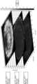
첫째, 치료를 위해 타겟된 조직이 얕을 때(예로서, 피부의 진피), 포물면 반사기를 이용할 때, 평면파의 피크 압력이 타겟된 조직을 초과하여 지속된다. 이러한 파는 타겟된 치료 부위 이외의 먼 조직 부위에서 원하지 않는 손상 효과 및 고통을 야기할 수 있다. 예를 들면, 진피를 치료할 때, 비교적 평탄한 파는 하부의 뼈 구조에 영향을 미치기에 충분한 피크 압력을 유지하여 환자에게 심각한 고통을 야기할 것이다. 포물선 반사기를 이용하는 전기유압식 충격파 발생기에 의해 생성된 영구 평면 음향 파 피크 압력의 형성은 상이한 조직 깊이에서 음향 파면의 압력 맵을 검사함으로써 입증된다. 예를 들면, 도 1은 표준 포물선 반사기를 이용하는 충격파 발생기로부터의 음향 파면 압력 맵을 묘사한다. 보여지는 바와 같이, 음향 파면 피크 압력 맵은 피크 압력의 지속적인 속성을 도시한다. 50mm 깊이에서, 음향 파면 피크 압력은 매우 높아서 30mm 깊이의 파면 피크 압력으로부터 본질적으로 변하지 않는다.First, when the tissue targeted for treatment is shallow (eg, the dermis of the skin), when using a parabolic reflector, the peak pressure of the plane wave persists beyond the targeted tissue. These waves can cause unwanted damaging effects and pain in distant tissue areas other than the targeted treatment area. For example, when treating the dermis, relatively flat waves will maintain enough peak pressure to affect the underlying bone structures, causing significant pain to the patient. The formation of a persistent planar acoustic wave peak pressure generated by an electrohydraulic shock wave generator using a parabolic reflector is demonstrated by examining the pressure maps of the acoustic wave front at different tissue depths. For example, Figure 1 depicts an acoustic wavefront pressure map from a shock wave generator using a standard parabolic reflector. As can be seen, the acoustic wavefront peak pressure map shows the continuous nature of the peak pressure. At 50 mm depth, the acoustic wave peak pressure is very high and essentially unchanged from the wave peak pressure at 30 mm depth.
둘째, 전기유압식 충격파 발생기에서 포물선 반사기의 이용을 통해 발생된 평면 음향 파는 종종 균일하지 못하다. 구체적으로, 전기유압식 충격파 발생기에서의 포물선 반사기는 더 높은 피크 압력 둘 모두(즉, "핫스팟") 또는 더 낮은 피크 압력(즉, "그림자")을 가지는 음향 파면을 생성할 수 있다. 음향 파면에서의 이 불균일성은 적어도 2개의 주된 소스를 갖는다: (1) 챔버 내에서 발생된 이상 음향 파 반사; 및 (2) 챔버 내의 전극 갭 위치의 불안정성.Second, the planar acoustic waves generated through the use of parabolic reflectors in electrohydraulic shock wave generators are often non-uniform. Specifically, parabolic reflectors in electrohydraulic shock wave generators can produce acoustic wavefronts with either higher peak pressures (i.e., “hotspots”) or lower peak pressures (i.e., “shadows”). This non-uniformity in the acoustic wavefront has at least two main sources: (1) anomalous acoustic wave reflections generated within the chamber; and (2) instability of the electrode gap position within the chamber.
이상 음향 파 반사는 전형적으로, 챔버 내에서 발견된 하드웨어(즉, 전극, 전극 브리지 등), 포트, 에지 등에 의해 야기된다. 이들 이상 반사는 종종, 피크 압력이 더 높고 피크 압력이 더 낮은 영역을 가지는 음향 파면의 형성을 야기할 것이다.Anomalous acoustic wave reflections are typically caused by hardware (i.e. electrodes, electrode bridges, etc.), ports, edges, etc. found within the chamber. These anomalous reflections will often result in the formation of an acoustic wavefront with regions of higher and lower peak pressures.
챔버 내의 전극 갭 위치의 불안정성은 전기유압식 충격파 발생기에서의 전극 사이의 갭에서 스파크를 생성하는 한 쌍의 전극으로부터 기인한다. 이 전기 스파크는 음향 파를 생성하기 위해 붕괴되는 플라즈마 버블을 야기한다. 전극이 포물면 반사기 내의 적절한 초점 위치에 배치될 때, 반사된 음향 파는 상대적으로 평탄한 파면의 형성을 야기할 수 있다. 그러나, 음향 파면의 불균일성은 전극 갭의 초점 위치("f 위치" 또는 "초점 포인트 위치")가 변할 때 발생할 수 있다. 스파크 이벤트로부터의 전극의 침식은 포물선 반사기 내의 스파크 이벤트의 초점 위치의 변화를 초래한다. 초점 위치의 이 불안정성은 출력된 음향 파의 불균일성을 야기한다. 도 2a 및 도 2b는 가변 전극 갭 초점 위치(200)의 영향을 나타내는 포물면 반사기(202)로부터 나오는 압력 라인의 그래프 표현을 묘사한다. 도 2a에서, 전극 갭(200)의 초점 위치는 f=0.93이고, 이는 압력 라인이 중심에서 수렴함을 야기한다. 이들 압력 라인의 이 수렴은 조직에서 더 깊은 피크 압력 핫스팟(204)을 야기하여 과도한 조직 손상, 치료 불편, 및 통증을 야기할 것이다. 유사하게, 도 2b에서, 전극 갭(200)의 초점 위치는 f=0.6이고, 이는 압력 라인이 치료 영역의 원주 주위로 수렴하는 것을 야기한다. 치료 영역의 원주 주위로의 압력 라인의 수렴은 조직에서 더 깊은 피크 압력 핫스팟(204)을 야기하여 과도한 조직 손상, 치료 불편, 및 통증을 야기할 것이다.The instability of the electrode gap position within the chamber results from a pair of electrodes generating a spark in the gap between the electrodes in an electrohydraulic shock wave generator. This electrical spark causes a plasma bubble to collapse to create an acoustic wave. When the electrodes are placed at an appropriate focal location within the parabolic reflector, the reflected acoustic waves can result in the formation of a relatively flat wavefront. However, non-uniformities in the acoustic wavefront can occur when the focal position (“f position” or “focus point position”) of the electrode gap changes. Erosion of the electrode from the spark event results in a change in the location of the focus of the spark event within the parabolic reflector. This instability in the focal position causes non-uniformity of the output acoustic wave. 2A and 2B depict graphical representations of pressure lines coming from
따라서, 포물선 반사기의 이용이 음향 파 피크 압력 지속성 및 음향 파 불균일성(즉, 핫스팟 및 그림자)으로 인해, 선택 처리 상황에서 안정적인 음향 파를 생성할 수 있지만, 종래 기술의 접근법은 지속적으로 균일한 음향 파면을 제공하는데 있어서 최적이 아니다. 결과적으로, 이들 음향 파면 지속성 및 핫스팟은 환자에게 고통스럽고 유해한 치료를 야기할 수 있다.Therefore, although the use of parabolic reflectors can produce stable acoustic waves in select processing situations, due to acoustic wave peak pressure persistence and acoustic wave non-uniformities (i.e. hotspots and shadows), prior art approaches consistently achieve uniform acoustic wave fronts. It is not optimal in providing . As a result, these acoustic wavefront persistence and hot spots can result in painful and harmful treatment for the patient.
D. 자유형 반사기D. Freeform reflector
자유형 반사기는 순수한 포물선이 아닌 반사기이다. 조명 분야에서, 광원 상의 자유형 반사기는 균일한 원형 조명을 제공하는데 도움이 되기 위해 이용되어 왔다. 그것의 높은 설계 자유로 인해, 자유형 표면은 광학 시스템의 구조를 단순화하고 복잡한 조명 요건을 만족시킬 수 있다. 지난 몇 년 동안 자유형 표면의 설계 및 가공 기술 개발로 인해, 이 기술은 도로 또는 탐색 조명, 프로젝터 조명, 액정 디스플레이(LCD) 백라이트, 자동차 헤드 램프, 및 광학 리소그래피 시스템, 등(Liu & 외, 2005년)[4]과 같은 많은 분야에 적용되어 왔다. 조명을 위한 자유형 반사기를 설계하는 것은 어렵다. 최근, 복수의 접근법이 설명되었다 [4]. 이들 접근법은 광의 이용에 특정한 특수 알고리즘 및 최적화 기술을 활용했다고 여겨진다. 광 출력을 위한 자유형 반사기의 예는 다음에서 발견될 수 있다: (1) 미국 특허 번호 제 5,790,305 호; (2) 미국 특허 출원 공보 제 US2010/0208467 호; (3) 미국 특허 번호 제 5,675,495 호; 및 (4) 미국 특허 번호 제 5,204,820 호.A freeform reflector is a reflector that is not purely parabolic. In the field of lighting, freeform reflectors on light sources have been used to help provide uniform circular illumination. Due to its high design freedom, the free-form surface can simplify the structure of the optical system and satisfy complex lighting requirements. Due to the development of design and processing technology of free-form surfaces in the past few years, this technology has been widely used in road or navigation lights, projector lights, liquid crystal display (LCD) backlights, automobile headlamps, and optical lithography systems, etc. (Liu & et al., 2005 ) has been applied to many fields such as [4]. Designing freeform reflectors for lighting is difficult. Recently, multiple approaches have been described [4]. These approaches are believed to utilize special algorithms and optimization techniques specific to the use of light. Examples of freeform reflectors for light output can be found in: (1) U.S. Pat. No. 5,790,305; (2) United States Patent Application Publication No. US2010/0208467; (3) U.S. Patent No. 5,675,495; and (4) U.S. Patent No. 5,204,820.
본 발명의 목적은 개선된 음향 파면을 갖는 치료 충격 파 또는 충격파(치료 용도의 충격 파)를 발생시키기 위한 장치 및 방법을 제공하는 것이다.The object of the present invention is to provide a device and method for generating therapeutic shock waves or shock waves (shock waves for therapeutic applications) with an improved acoustic wavefront.
본 발명은 개선된 음향 파면을 갖는 급속 음향 펄스의 전기유압식 발생을 위한 장치 및 방법의 실시예를 포함한다. 특정 실시예에서, 이들 개선된 음향 파면은 정의된 거리 다음에 신속하게 분산되는 타겟된 치료 영역의 근거리 장에서 본질적으로 평면인 음향 파면을 포함한다. 이러한 파면은 조직 손상 및 통증을 타겟된 영역을 넘어 제한하면서, 타겟된 영역에서 효과적인 음향 치료를 제공한다. 또 다른 실시예에서, 개선된 음향 파면은 정의된 거리 다음에 신속하게 분산되는 타겟된 치료 영역의 근거리 장에서 본질적으로 평탄한 집속되지 않은 음향 파면을 포함하고, 여기서 음향 파면은 본질적으로, 피크 압력의 면에서 본질적으로 일정하다. 이러한 파면은 피크 압력의 높은 농도(즉, "핫스팟") 및 피크 압력의 낮은 농도(즉, "그림자")를 최소화하는 타겟된 영역에서 효과적인 음향 치료를 제공한다. 이들 본질적으로 균일한 집속되지 않은 음향 파면은 타겟된 치료 영역에 대해 더 일관성 있는 치료를 제공한다.The present invention includes embodiments of an apparatus and method for electrohydraulic generation of rapid acoustic pulses with improved acoustic wavefronts. In certain embodiments, these improved acoustic wavefronts include essentially planar acoustic wavefronts in the near field of the targeted treatment area that disperse rapidly over a defined distance. These wavefronts provide effective acoustic therapy in the targeted area, while limiting tissue damage and pain beyond the targeted area. In another embodiment, the improved acoustic wavefront comprises an essentially flat, unfocused acoustic wavefront in the near field of the targeted treatment area that disperses rapidly over a defined distance, wherein the acoustic wavefront is essentially flat at a peak pressure of essentially constant in terms of These wavefronts provide effective acoustic treatment in targeted areas minimizing high concentrations of peak pressure (i.e., “hot spots”) and low concentrations of peak pressure (i.e., “shadows”). These inherently uniform, non-focused acoustic wavefronts provide more consistent treatment over the targeted treatment area.
특정 실시예에서, 음향 파의 전기유압식 발생을 위한 장치는: 챔버 및 충격파 유출구를 정의하는 하우징; 챔버에 배치된 액체; 챔버 내의 음향 반사기; 하나 이상의 스파크 갭을 형성하기 위해 챔버에 배치되도록 구성된 복수의 전극(예로서, 스파크 헤드 또는 모듈에서의); 및 10Hz와 5MHz 사이의 레이트로 전극에 전압 펄스를 인가하도록 구성된 펄스 발생 시스템을 포함한다. 하나의 실시예에서, 개선된 음향 파면은 챔버에서 음향 반사기를 이용하여 성취된다. 또 다른 실시예에서, 개선된 음향 파면은 챔버에서 음향 자유형 반사기를 이용하여 성취된다. 여전히 또 다른 실시예에서, 개선된 음향 파면은 챔버에서 안정적인 스파크 갭 위치를 제공함으로써 성취된다. 여전히 또 다른 실시예에서, 개선된 음향 파면은 챔버에서 안정적인 스파크 갭 위치 및 음향 자유형 반사기의 이용을 통해 성취된다.In a particular embodiment, a device for electrohydraulic generation of acoustic waves includes: a housing defining a chamber and a shock wave outlet; a liquid placed in the chamber; an acoustic reflector within the chamber; a plurality of electrodes (e.g., in a spark head or module) configured to be disposed in the chamber to form one or more spark gaps; and a pulse generation system configured to apply voltage pulses to the electrode at a rate between 10 Hz and 5 MHz. In one embodiment, improved acoustic wavefront is achieved using acoustic reflectors in the chamber. In another embodiment, improved acoustic wavefront is achieved using acoustic freeform reflectors in the chamber. In yet another embodiment, improved acoustic wavefront is achieved by providing a stable spark gap position in the chamber. In yet another embodiment, improved acoustic wavefront is achieved through the use of acoustic freeform reflectors and stable spark gap position in the chamber.
본 장치(예로서, 치료용 음향 파를 발생시키기 위한)의 일부 실시예는: 액체를 수용하도록 구성된 챔버 및 충격파 유출구를 정의하는 하우징; 하나 이상의 스파크 갭을 형성하기 위해 챔버에 배치되도록 구성된 복수의 전극; 챔버에 배치된 음향 반사기; 및 복수의 전극에 기계적으로 결합된 단일 서보모터(servomotor)를 포함하고; 여기서, 스파크 갭은 스파크 갭 크기 및 스파크 갭 위치를 갖고; 여기서, 단일 서보모터는 일관된 스파크 갭 크기 및 스파크 갭 위치를 유지하기 위해 전극의 각각을 조정하도록 구성된다. 일부 실시예에서, 음향 반사기는 자유형 음향 반사기이다. 일부 실시예에서, 복수의 전극은 제 1 전극 및 제 2 전극을 포함하고; 단일 서보모터는 제 1 전극 및 제 2 전극에 기계적으로 결합된다. 일부 실시예는: 제 2 전극에 기계적으로 결합된 복수의 피벗 암(pivot arms)을 더 포함한다. 일부 실시예에서, 복수의 피벗 암은 단일 서보모터가 작동될 때 제 1 전극 쪽으로 제 2 전극을 전진시키도록 구성된다. 일부 실시예는: 복수의 전극을 이동시키고 스파크 갭을 일정한 길이로 유지하기 위해 폐쇄형 루프 제어를 통해 단일 서보모터를 시그널링(signalling)하도록 구성된 제어기를 더 포함한다. 일부 실시예에서, 제어기는 또한,: 식별된 충전 전압에서 복수의 전극의 방전의 펄스 시간을 측정하고; 측정된 펄스 시간에 기초하여 이동시키기 위해 단일 서보모터를 시그널링하여, 그에 의해 스파크 갭을 일관된 길이로 유지시킴으로써 폐쇄형 루프 제어를 통해 단일 서보모터를 시그널링하도록 구성된다. 일부 실시예는: (i) 하우징이 펄스 발생 시스템에 대해 이동가능하고, (ii) 펄스 발생 시스템이 복수의 전극과 전기 통신하도록 복수의 전극에 결합되도록 구성된 펄스 발생 시스템을 더 포함한다.Some embodiments of the device (e.g., for generating therapeutic acoustic waves) include: a housing defining a shock wave outlet and a chamber configured to contain a liquid; a plurality of electrodes configured to be disposed in the chamber to form one or more spark gaps; an acoustic reflector disposed in the chamber; and a single servomotor mechanically coupled to the plurality of electrodes; Here, the spark gap has a spark gap size and a spark gap location; Here, a single servomotor is configured to adjust each of the electrodes to maintain consistent spark gap size and spark gap position. In some embodiments, the acoustic reflector is a freeform acoustic reflector. In some embodiments, the plurality of electrodes includes a first electrode and a second electrode; A single servomotor is mechanically coupled to the first and second electrodes. Some embodiments further include: a plurality of pivot arms mechanically coupled to the second electrode. In some embodiments, the plurality of pivot arms are configured to advance the second electrode toward the first electrode when the single servomotor is actuated. Some embodiments further include a controller configured to: signal a single servomotor through closed loop control to move the plurality of electrodes and maintain the spark gap at a constant length. In some embodiments, the controller may also: measure the pulse time of discharge of the plurality of electrodes at the identified charging voltage; and configured to signal a single servomotor through closed loop control by signaling the single servomotor to move based on the measured pulse time, thereby maintaining the spark gap at a consistent length. Some embodiments further include a pulse generation system configured to: (i) have the housing moveable relative to the pulse generation system, and (ii) be coupled to a plurality of electrodes such that the pulse generation system is in electrical communication with the plurality of electrodes.
본 장치(예로서, 치료용 음향 파를 발생시키기 위한)의 일부 실시예는: 챔버 및 충격파 유출구를 정의하는 하우징; 챔버에 배치된 액체; 액체를 수용하도록 구성된 챔버 및 충격파 유출구를 정의하는 하우징; 하나 이상의 스파크 갭을 형성하기 위해 챔버에 배치되도록 구성된 복수의 전극; 및 챔버에 배치된 자유형 음향 반사기를 포함하고, 여기서 스파크 갭은 스파크 갭 크기 및 스파크 갭 위치를 갖는다. 일부 실시예에서, 음향 반사기는 하우징과 통합된다.Some embodiments of the device (e.g., for generating therapeutic acoustic waves) include: a housing defining a chamber and a shock wave outlet; a liquid placed in the chamber; a housing defining a shock wave outlet and a chamber configured to contain a liquid; a plurality of electrodes configured to be disposed in the chamber to form one or more spark gaps; and a freeform acoustic reflector disposed in the chamber, wherein the spark gap has a spark gap size and a spark gap location. In some embodiments, the acoustic reflector is integrated with the housing.
본 방법(예로서, 자유형 음향 반사기를 설계하기 위한)의 일부 실시예는: 음향 펄스의 원점, 환자의 타겟 치료 영역, 및 안전 깊이를 정의하는 단계; 지정된 타겟 치료 영역과 일치하는 에너지 분포를 유발할 수 있는 반사기 형상 및 안전 깊이가 성취될 때까지 반사기 형상을 반복하는 단계; 최종 반사기 형상에 기초하여 에너지 밀도를 근사화하는 단계; 및 최종 반사기 형상을 검증하는 단계를 포함한다. 일부 실시예에서, 음향 펄스의 원점을 정의하는 단계는 복수의 전극이 전기유압식 음향 파 발생기에서 위치되는 위치를 정의하는 단계를 더 포함한다. 일부 실시예에서, 환자의 타겟 치료 영역을 정의하는 단계는 균일한 압력 밀도를 전달할 조직 깊이를 지정하는 단계를 더 포함한다. 일부 실시예에서, 안전 깊이를 정의하는 단계는 집속되지 않은 음향 파가 50%만큼 소멸되는 환자의 조직에서 깊이를 결정하는 단계를 더 포함한다. 일부 실시예에서, 반사기 형상을 반복하는 단계는 스플라인 보간법(spline interpolation)을 이용하는 단계를 더 포함한다. 일부 실시예에서, 에너지 밀도를 근사화하는 단계는 광선 추적을 수행하는 단계를 더 포함한다. 일부 실시예에서, 최종 반사기 형상을 검증하는 단계는 유한 요소법(finite element method; FEM) 시뮬레이션을 이용하는 단계를 더 포함한다.Some embodiments of the method (e.g., for designing a freeform acoustic reflector) include: defining an origin of the acoustic pulse, a target treatment area of the patient, and a safety depth; Iterating the reflector shape until a safe depth and reflector shape that will result in an energy distribution consistent with the designated target treatment area is achieved; approximating the energy density based on the final reflector shape; and verifying the final reflector shape. In some embodiments, defining the origin of the acoustic pulse further includes defining positions at which the plurality of electrodes are located in the electrohydraulic acoustic wave generator. In some embodiments, defining a target treatment area of the patient further includes specifying a tissue depth that will deliver a uniform pressure density. In some embodiments, defining the safe depth further includes determining a depth in the patient's tissue at which unfocused acoustic waves are extinguished by 50%. In some embodiments, repeating the reflector shape further includes using spline interpolation. In some embodiments, approximating the energy density further includes performing ray tracing. In some embodiments, verifying the final reflector shape further includes using finite element method (FEM) simulation.
용어("결합된")는 반드시 직접적으로가 아니고 반드시 기계적으로도 아닐지라도, 연결된 것으로서 정의되고; "결합되는" 2개의 아이템은 서로 통합될 수 있다. 용어("a" 및 "an")는 본 발명이 달리 명시적으로 요구하지 않는다면 하나 이상으로서 정의된다. 용어("실질적으로")는 당업자에 의해 이해되는 바와 같이, 주로 그러나 반드시 전체적으로는 아닌 특정되는 것으로서 정의된다(및 특정되는 것을 포함한다; 예로서, 실질적으로 90도는 90도를 포함하며 실질적으로 평행은 평행을 포함한다). 어떤 개시된 실시예에서, 용어("실질적으로", "대략", 및 "약")은 특정되는 것"의 [퍼센티지] 내에서"으로 대체될 수 있으며, 여기서 퍼센티지는 .1, 1, 5, 및 10퍼센트를 포함한다. 개시된 실시예에서, 용어("인접한")는 일반적으로, 동일한 별개의 챔버, 하우징, 또는 모듈에 위치되는 것으로 정의된다.The term (“joined”) is defined as connected, although not necessarily directly and not necessarily mechanically; Two items that are "combined" can be integrated into each other. The terms “a” and “an” are defined as more than one unless the invention explicitly requires otherwise. The term (“substantially”) is defined (and includes what is specified) primarily, but not necessarily entirely, as understood by those skilled in the art; for example, substantially 90 degrees includes 90 degrees and is substantially parallel. includes parallel). In some disclosed embodiments, the terms (“substantially,” “approximately,” and “about”) may be replaced with “within [a percentage] of that being specified,” wherein the percentage is .1, 1, 5, and 10 percent. In the disclosed embodiments, the term “adjacent” is generally defined as located in the same separate chamber, housing, or module.
용어("포함하다(comprise)"(및 "포함하다" 및 "포함하는"과 같은, 어떤 형태의 포함하다)), "갖다(have)"(및 "갖다" 및 "가지는"과 같은, 어떤 형태의 갖다), "포함시키다(include)"(및 "포함시키다" 및 "포함시키는"과 같은 어떤 형태의 포함시키다) 및 "함유하다(contain)"(및 "함유하다" 및 "함유하는"과 같은 어떤 형태의 함유하다)는 확장가능한 연결 동사이다. 결과적으로, 하나 이상의 요소를 "포함하는", "갖는", "포함시키는" 또는 "함유하는" 시스템 또는 장치는 이들 하나 이상의 요소를 소유하지만, 단지 이들 요소만을 소유하는 것으로 제한되지 않는다. 마찬가지로, 하나 이상의 단계를 "포함하는", "갖는", "포함시키는" 또는 "함유하는" 방법은 이들 하나 이상의 단계를 소유하지만, 단지 이들 하나 이상의 단계만을 소유하는 것으로 제한되지 않는다.The terms "comprise" (and any form of inclusion, such as "including" and "comprising"), "have" (and any form of inclusion, such as "have" and "having") “have the form of”, “include” (and some forms of include, such as “including” and “including”) and “contain” (and “include” and “containing”) Contains some forms such as) is an expandable linking verb. As a result, a system or device that “comprises,” “has,” “includes,” or “contains” one or more elements possesses one or more of these elements, but is not limited to possessing only these elements. Likewise, a method “comprising,” “having,” “comprising,” or “containing” one or more steps possesses those one or more steps, but is not limited to possessing only these one or more steps.
게다가, 특정 방식으로 구성되는 구조(예로서, 장치의 부품)는 적어도 상기 방식으로 구성되지만, 그것은 또한, 구체적으로 설명된 것 외에 다른 방식으로 구성될 수 있다.Moreover, although a structure (e.g., a component of a device) that is configured in a particular way is configured in at least that way, it may also be configured in other ways than those specifically described.
본 시스템, 장치, 및 방법 중 어떤 것의 어떤 실시예는 포함하는/포함시키는/함유하는/갖기보다는 설명된 단계, 요소, 및/또는 특징 중 어떤 것으로 이루어지거나 근본적으로 이루어질 수 있다. 따라서, 청구항 중 어떤 것에서, 용어("~로 이루어진" 또는 "~로 근본적으로 이루어진")는 그것이 그렇지 않으면, 확장가능한 연결 동사를 이용하는 것으로부터 주어진 청구항의 범위를 변경하기 위해, 상기 인용된 확장가능한 연결 동사 중 어떤 것에 대해 대체될 수 있다.Certain embodiments of any of the present systems, devices, and methods may consist of or consist essentially of any of the steps, elements, and/or features described rather than including/comprising/containing/having. Accordingly, in any of the claims, the term ("consisting of" or "consisting essentially of") may be used to alter the scope of a given claim from otherwise using an expandable linking verb, such as a recited expandable verb. It can be substituted for any of the linking verbs.
상기 설명된 실시예와 연관된 상세 및 다른 것이 이하에서 제공된다.Details and others related to the above-described embodiments are provided below.
다음의 설명은 제한이 아닌 예로서 도시한다. 간결성 및 명료함을 위해, 주어진 구조의 모든 특징은 항상, 상기 구조가 나타나는 모든 도면에서 라벨링되는 것은 아니다. 동일한 참조 부호는 반드시 동일한 구조를 나타내는 것은 아니다. 오히려, 동일한 참조 부호는 동일하지 않은 참조 부호일 수 있는 바와 같이, 유사한 기능을 갖는 유사한 특징 또는 특징을 나타내기 위해 이용될 수 있다. 도면은 일정한 비율로 그려지고(달리 언급되지 않는다면), 이는 묘사된 요소의 크기가 적어도 도면에 묘사된 실시예에 대해서 서로에 대해 정확하다는 것을 의미한다.The following description is presented by way of example and not limitation. For the sake of brevity and clarity, not all features of a given structure are always labeled in every drawing in which that structure appears. Identical reference signs do not necessarily indicate identical structures. Rather, like reference signs may be used to indicate similar features or features having similar functions, just as non-identical reference signs may. The drawings are drawn to scale (unless otherwise noted), which means that the sizes of the depicted elements are accurate relative to each other, at least for the embodiment depicted in the drawings.
도 1은 표준 포물선 반사기를 이용하는 종래의 충격파 발생기로부터의 음향 파면 압력 맵을 묘사한 도면.
도 2a 및 도 2b는 포물선 반사기로부터 나오는 압력 라인의 그래픽 표현을 묘사한 도면.
도 3은 정의된 음향 파면을 가지는 자유형 음향 반사기를 설계하기 위한 최적화 프로세스에 대한 흐름도.
도 4는 자유형 반사기로부터 반사된 음향 파의 광선 추적의 그래픽 표현을 묘사한 도면.
도 5는 스플라인 보간법을 이용하여 설계된 자유형 반사기의 FEM 시뮬레이션을 묘사한 도면.
도 6a 및 도 6b는 각각 장치의 스파크헤드 부분의 등가 및 단면도.
도 7은 표준 포물선 반사기를 이용하는 종래의 충격파 발생기로부터의 음향 파면 압력 맵을 도시한 도면.
도 8은 포물선 반사기 및 자유형 반사기의 음향 파면 압력 맵을 나란히 비교 한 도면.
도 9는 캐소드 및 애노드 전극 부식 레이트 비에 관한 실험 데이터를 제공하는 그래프.
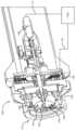
도 10은 개선된 음향 파면을 가지는 음향 파의 전기유압식 발생을 위한 장치의 하나의 실시예의 단면도.
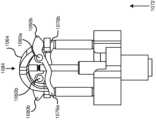
도 11은 도 10의 장치의 특정 부품의 사시도.
도 12a 내지 도 12c는 도 11의 부품의 기능을 도시하는 3개의 도면.Figure 1 depicts an acoustic wavefront pressure map from a conventional shock wave generator using a standard parabolic reflector.
2A and 2B depict graphical representations of pressure lines emerging from a parabolic reflector;
Figure 3 is a flow chart of the optimization process for designing a free-form acoustic reflector with defined acoustic wavefront.
Figure 4 depicts a graphical representation of a ray trace of an acoustic wave reflected from a freeform reflector.
Figure 5 depicts an FEM simulation of a freeform reflector designed using spline interpolation.
6A and 6B are equivalent and cross-sectional views, respectively, of the sparkhead portion of the device.
Figure 7 shows an acoustic wavefront pressure map from a conventional shock wave generator using a standard parabolic reflector.
Figure 8 shows a side-by-side comparison of the acoustic wavefront pressure maps of a parabolic reflector and a freeform reflector.
9 is a graph providing experimental data regarding cathode and anode electrode corrosion rate ratios.
Figure 10 is a cross-sectional view of one embodiment of a device for electrohydraulic generation of acoustic waves with an improved acoustic wavefront.
Figure 11 is a perspective view of certain components of the device of Figure 10;
Figures 12A-12C are three diagrams showing the function of the components of Figure 11;
본 시스템 및 장치의 특정 실시예는 개선된 음향 파면을 갖는 고 주파수 충격 파를 발생시키도록 구성된다. 일부 실시예에서, 발생된 EH 음향 펄스는 의료 및/또는 미학적 치료 애플리케이션에서 이용될 수 있다(예로서, 환자의 타겟 조직으로 지향되고/되거나 그것으로 전달될 때). 본 시스템이 이용될 수 있는 의료 및/또는 미학적 치료 애플리케이션의 예는: (1) US 2013/0046207로서 공개된 미국 특허 출원 번호 제 13/574,228 호; (2) US 2013/0018287로서 공개된 미국 특허 출원 번호 제 13/547,995 호; 및 (3) US 2014/0257144로서 공개된 미국 특허 출원 번호 제 13/798,710 호에서 개시되며, 그들의 각각은 본 명세서에 전체적으로 통합된다.Certain embodiments of the present systems and devices are configured to generate high frequency shock waves with improved acoustic wavefronts. In some embodiments, the generated EH acoustic pulses may be used in medical and/or aesthetic therapy applications (e.g., when directed to and/or delivered to target tissue of a patient). Examples of medical and/or aesthetic treatment applications in which the present system may be used include: (1) U.S. Patent Application No. 13/574,228, published as US 2013/0046207; (2) U.S. Patent Application No. 13/547,995, published as US 2013/0018287; and (3) U.S. Patent Application No. 13/798,710, published as US 2014/0257144, each of which is hereby incorporated in its entirety.
하나의 실시예에서, 충격파의 전기유압식 발생을 위한 장치는: 챔버 및 충격파 유출구를 정의하는 하우징; 챔버에 배치된 액체; 하나 이상의 스파크 갭을 형성하기 위해 챔버에 배치되도록 구성된 복수의 전극(예로서, 스파크 헤드 또는 모듈에서의); 및 10Hz와 5MHz 사이의 레이트로 전압 펄스를 전극에 인가하도록 구성된 펄스 발생 시스템을 포함한다. 전압 펄스의 레이트는 25Hz, 50Hz, 75Hz, 100Hz, 150Hz, 200Hz, 250Hz, 300Hz, 400Hz, 500Hz, 600Hz, 700Hz, 800Hz, 900Hz, 1KHz, 5KHz, 10KHz, 25KHz, 50KHz, 100KHz, 200KHz, 300KHz, 400KHz, 500KHz, 600KHz, 700KHz, 800KHz, 900KHz, 1MHz, 2MHz, 3MHz, 및 4MHz의 레이트에 있을 수 있다.In one embodiment, a device for electrohydraulic generation of shock waves includes: a housing defining a chamber and a shock wave outlet; a liquid placed in the chamber; a plurality of electrodes (e.g., in a spark head or module) configured to be disposed in the chamber to form one or more spark gaps; and a pulse generation system configured to apply voltage pulses to the electrode at a rate between 10 Hz and 5 MHz. The rates of voltage pulses are 25Hz, 50Hz, 75Hz, 100Hz, 150Hz, 200Hz, 250Hz, 300Hz, 400Hz, 500Hz, 600Hz, 700Hz, 800Hz, 900Hz, 1KHz, 5KHz, 10KHz, 25KHz, 50KHz, 100KHz, 200KHz, 300KHz, 400KHz , 500KHz, 600KHz, 700KHz, 800KHz, 900KHz, 1MHz, 2MHz, 3MHz, and 4MHz.
일부 실시예에서, 펄스 발생 시스템은 개선된 음향 파면을 갖는 일련의 음향 충격파를 생성하도록 구성된다. 개선된 음향 파면은 정의된 거리 후에 신속하게 분산되는 타겟된 치료 영역의 근거리 장에서 본질적으로 평탄한 음향 파면을 포함한다. 이러한 파면은 타겟된 치료 영역에서 효과적인 음향 치료를 제공하지만, 조직 손상 및 통증을 그 타겟된 영역을 넘어서는 것으로 제한한다. 일부 실시예에서, 개선된 음향 파면은 음향 파면이 피크 압력의 면에서 본질적으로 일정한 정의된 거리 후에 신속하게 분산되는 타겟된 치료 영역의 근거리 장에서 본질적으로 평탄한 집속되지 않은 음향 파면을 포함한다. 이러한 파면은 피크 압력의 높은 농도(즉, "핫스팟") 및 피크 압력의 낮은 농도(즉, "그림자")를 최소화하는 타겟된 영역에서 효과적인 음향 치료를 허용한다. 본질적으로 균일하고 집속되지 않은 음향 파면을 가지는 것은 타겟된 치료 영역에 대해 더 일관성 있는 치료를 제공한다.In some embodiments, the pulse generation system is configured to generate a series of acoustic shock waves with improved acoustic wavefronts. The improved acoustic wavefront includes an essentially flat acoustic wavefront in the near field of the targeted treatment area that disperses rapidly after a defined distance. These wavefronts provide effective acoustic therapy in the targeted treatment area, but limit tissue damage and pain beyond that targeted area. In some embodiments, the improved acoustic wavefront comprises an essentially flat, non-focused acoustic wavefront in the near field of the targeted treatment area where the acoustic wavefront disperses rapidly after a defined distance, which is essentially constant in terms of peak pressure. These wavefronts allow for effective acoustic treatment in targeted areas minimizing high concentrations of peak pressure (i.e., “hot spots”) and low concentrations of peak pressure (i.e., “shadows”). Having an inherently uniform, non-focused acoustic wavefront provides more consistent treatment over the targeted treatment area.
특정 실시예에서, 개선된 음향 파형(예로서, 음향 파면)은 챔버에서 음향 반사기를 이용하여 성취된다. 더 구체적으로, 특정 실시예는 원하는 파면을 성취하기 위해 자유형 음향 반사기를 이용한다. 여전히 또 다른 실시예에서, 개선된 음향 파면은 챔버에서 안정적인 스파크 갭 위치를 제공함으로써 성취된다. 안정화된 음향 파면은 복수의 전극으로부터 형성된 스파크 갭을 챔버 내의 일정한 초점 위치에 유지함으로써 성취된다. 하나의 실시예에서, 복수의 전극은 챔버 내의 일정한 초점 위치에서 스파크 갭을 유지하기 위해 이용된 단일 서보모터를 포함하는 초점 안정화 유닛을 통해 자동적으로 조정된다. 개시된 장치의 특정 실시예는 자유형 음향 반사기 및 초점 안정화 유닛 둘 모두를 포함한다.In certain embodiments, improved acoustic waveforms (e.g., acoustic wavefronts) are achieved using acoustic reflectors in the chamber. More specifically, certain embodiments utilize freeform acoustic reflectors to achieve the desired wavefront. In yet another embodiment, improved acoustic wavefront is achieved by providing a stable spark gap position in the chamber. A stabilized acoustic wavefront is achieved by maintaining a spark gap formed from a plurality of electrodes at a constant focal position within the chamber. In one embodiment, the plurality of electrodes are automatically adjusted through a focus stabilization unit that includes a single servomotor used to maintain the spark gap at a constant focus position within the chamber. Particular embodiments of the disclosed device include both a freeform acoustic reflector and a focus stabilization unit.
A. 자유형 반사기A. Freeform reflector
자유형 반사기가 조명 목적을 위해 이용되었지만, 음향 출력을 위해 자유형 반사기를 이용하는 것은 어렵고 비실용적이다. 예를 들면, 광파는 음향 파보다 상당히 작아서, 광에 대해 자유형 반사기를 설계하기 위한 현재의 접근법이 더 긴 파 음향 출력을 위해 이용될 때 훨씬 더 도전적이 되게 할 것이다. 부가적으로, 필라멘트 램프 또는 LED와 같은 광원과는 달리, 음향 소스는 전형적으로 커서(예로서, 반드시 "포인트 소스"는 아님), 자유형 비평면 음향 반사기의 설계를 더욱 어렵게 만든다.Although freeform reflectors have been used for lighting purposes, it is difficult and impractical to use freeform reflectors for acoustic output. For example, light waves are significantly smaller than acoustic waves, making current approaches for designing freeform reflectors for light much more challenging when used for longer wave acoustic output. Additionally, unlike light sources such as filament lamps or LEDs, acoustic sources are typically large (eg, not necessarily “point sources”), making the design of freeform non-planar acoustic reflectors more difficult.
포물선 반사기를 이용하는 음향 파의 전기유압식 발생에 대한 현재의 접근법은 일부의 경우에 차선책이다. 예를 들면, 포물면 반사기는 음향 파 불균일성을 완화시킬 수 없고, 그에 의해 핫스팟 및 그림자를 야기한다. 상기 논의된 바와 같이, 음향 파 불균일성의 2가지 주요 소스는: (1) 챔버 내에서 발생된 이상 음향 파 반사; 및 (2) 전극 갭의 초점 위치("f 위치")를 변화시키는 것이다.Current approaches to electrohydraulic generation of acoustic waves using parabolic reflectors are suboptimal in some cases. For example, parabolic reflectors cannot alleviate acoustic wave non-uniformities, thereby causing hot spots and shadows. As discussed above, the two main sources of acoustic wave non-uniformity are: (1) anomalous acoustic wave reflections generated within the chamber; and (2) changing the focal position (“f position”) of the electrode gap.
이상 반사는 전형적으로, 챔버 내에서 발견된 하드웨어(즉, 전극, 전극 브릿지 등), 포트, 에지 등에 의해 야기된다. 이들 이상 음향 파 반사는 더 높은 피크 압력의 영역 및 더 낮은 피크 압력의 영역을 가지는 음향 파면의 형성을 야기할 것이다. 전극 갭의 초점 위치의 변화는 스파크 이벤트로부터 야기된 전극의 침식으로부터 발생할 수 있다.Abnormal reflections are typically caused by hardware (i.e. electrodes, electrode bridges, etc.), ports, edges, etc. found within the chamber. These anomalous acoustic wave reflections will result in the formation of an acoustic wavefront with regions of higher peak pressure and regions of lower peak pressure. Changes in the focal position of the electrode gap may result from erosion of the electrode resulting from a spark event.
실제로, 음향 파의 불균일성은 문제가 될 수 있다. 이상 음향 파 및 변화하는 전극 갭 위치 둘 모두는 치료 영역에서 파면 수렴 및 발산을 일으켜 높은 압력의 영역(핫스팟) 및 낮은 압력의 영역(그림자)을 초래한다. 이들 음향 파면 핫스팟은 타겟 치료 영역 안팎에 국부적인 높은 압력 영역으로 이어져서 조직 손상 및/또는 통증을 야기할 수 있다. 음향 파면 그림자는 치료 효과가 떨어지는 음향 파 전달의 영역을 유발한다.In practice, non-uniformity of acoustic waves can be a problem. Both anomalous acoustic waves and changing electrode gap positions cause wavefront convergence and divergence in the treatment area, resulting in areas of high pressure (hotspots) and areas of low pressure (shadows). These acoustic wavefront hotspots can lead to localized high pressure areas in and around the targeted treatment area, causing tissue damage and/or pain. Acoustic wavefront shadows cause areas of acoustic wave transmission that are less therapeutic.
상기 논의된 바와 같이, 자유형 반사기는 현재, 조명 및 광학 분야에서 유사한 문제를 완화시키기 위해 이용된다. 그러나, 또한 상기 논의한 바와 같이, 음향 출력을 위해 자유형 반사기를 이용하는 것은 현재, 광과 음향 파 사이의 고유한 차이로 인해 어렵고 비현실적이다. 이들 도전에도 불구하고, 본 발명의 일부 실시예에 따르면, 자유형 반사기는 더 깊은 깊이에서 음향 파 지속성을 최소화하면서 정의된 처리 깊이에서 개선된 음향 파면 출력 균일성을 제공하도록 설계될 수 있다. 이들 자유형 반사기는 챔버 내에 위치된 구조(즉, 전극, 전극 브릿지, 워터 포트(water ports), 챔버 에지, 등)를 설명하면서 음향 핫스팟을 최소화하도록 설계된다.As discussed above, freeform reflectors are currently used to alleviate similar problems in lighting and optics. However, as also discussed above, utilizing freeform reflectors for acoustic output is currently difficult and impractical due to the inherent differences between optical and acoustic waves. Despite these challenges, according to some embodiments of the present invention, freeform reflectors can be designed to provide improved acoustic wavefront output uniformity at a defined processing depth while minimizing acoustic wave persistence at deeper depths. These freeform reflectors are designed to minimize acoustic hotspots while accounting for structures located within the chamber (i.e., electrodes, electrode bridges, water ports, chamber edges, etc.).
이제 도면을 참조하면, 도 3은 정의된 음향 파면을 가지는 자유형 음향 반사기를 설계하기 위한 최적화 프로세스를 묘사한다. 예로서, 자유형 음향 반사기는 스플라인 보간법을 이용하여 설계되고/되거나 개선(예로서, 최적화)될 수 있다. 도 3의 프로세스는 예를 들면, 메모리에 결합된 프로세서에 의해 컴퓨터 구현되고 메모리에 저장된 지시를 실행하여 프로세서로 하여금 도 3의 프로세스를 실행하기 위한 동작을 수행하게 하도록 구성될 수 있다.Referring now to the drawings, Figure 3 depicts the optimization process for designing a freeform acoustic reflector with a defined acoustic wavefront. As an example, a freeform acoustic reflector may be designed and/or improved (e.g., optimized) using spline interpolation. The process of Figure 3 may be computer implemented, for example, by a processor coupled to a memory and configured to execute instructions stored in the memory to cause the processor to perform operations to execute the process of Figure 3.
도시된 실시예에서, 정의된 파면을 가지는 자유형 음향 반사기를 설계하기 위한 최적화 프로세스는: (1) 음향 펄스의 원점을 정의하는 단계(300); (2) 치료 영역을 정의하는 단계(302); (3) 안전 깊이를 정의하는 단계(304); (4) 원하는 형상이 성취될 때까지 스플라인 보간법을 이용하여 반사기 형상을 반복하는 단계(306); (5) 대략적인 에너지 밀도에 대해 광선 추적을 수행하는 단계(308); 및 (6) 유한 요소법(FEM) 시뮬레이션을 이용하여 결과적인 구조를 검증하는 단계(310)를 포함한다.In the depicted embodiment, the optimization process for designing a freeform acoustic reflector with a defined wavefront includes: (1) defining the origin of the acoustic pulse (300); (2) defining a treatment area (302); (3) defining a safety depth (304); (4) repeating the reflector shape using spline interpolation until the desired shape is achieved (306); (5) performing ray tracing for the approximate energy density (308); and (6) verifying the resulting structure using finite element method (FEM) simulation (310).
도시된 실시예에서, 음향 펄스의 원점이 식별되거나 정의된다(300). 예를 들면, 음향 펄스의 원점은 전형적으로, 전기유압식 음향 파 발생기의 챔버에서 하나 이상의 스파크 갭을 정의하는 전극에 또는 그 사이에 있다. 이러한 전기유압식 발전기에서, 대향 전극은 종종, 펄스를 발생시키기 위해 이용된다. 전극이 평평한 면을 가질 때, 음향 펄스의 원점은 전형적으로, 그의 중심보다 전극의 에지에 있다. 이것은 종종, 음향 파가 에지에 도달할 때까지 음향 파가 평행 전극면 사이에서 앞뒤로 반사될 것이기 때문에 방전 이벤트의 위치와 상관없이 사실이다. 다른 실시예에서, 음향 펄스의 원점은 전자기 음향 파 발생기, 또는 압전 음향 파 발생기일 수 있다.In the depicted embodiment, the origin of the acoustic pulse is identified or defined (300). For example, the origin of the acoustic pulse is typically at or between electrodes defining one or more spark gaps in the chamber of an electrohydraulic acoustic wave generator. In these electrohydraulic generators, opposing electrodes are often used to generate pulses. When the electrode has a flat surface, the origin of the acoustic pulse is typically at the edge of the electrode rather than at its center. This is often true regardless of the location of the discharge event because the acoustic wave will bounce back and forth between parallel electrode planes until it reaches an edge. In other embodiments, the origin of the acoustic pulse may be an electromagnetic acoustic wave generator, or a piezoelectric acoustic wave generator.
도시된 실시예에서, 균일한 압력 밀도가 요구되는 조직 깊이를 정의하는 것을 포함하여, 타겟 치료 영역이 그 다음 정의되거나 명시된다(302). 예를 들면, 문신을 처리하는 맥락에서, 균일한 압력 밀도를 갖기 위한 타겟 치료 영역(400)은 깊이가 2mm 미만(예로서, 환자의 피부 표면으로부터)이다. 다른 맥락에서, 균일한 압력 밀도를 갖기 위한 타겟 치료 영역은 환자의 피부의 표면으로부터 깊이가 1mm, 3mm, 4mm, 5mm, 또는 1cm일 수 있다.In the depicted embodiment, the target treatment area is then defined or specified (302), including defining the tissue depth at which uniform pressure density is desired. For example, in the context of treating a tattoo, a
다음, 일 실시예에 따르면, 환자의 조직에서의 안전 깊이가 정의된다(304). 안전 깊이는 환자에게 조직 손상 및 통증을 최소화하기 위해 집속되지 않은 음향 파를 2배만큼 소멸시켜야 하는 포인트 또는 깊이이다. 이 안전 깊이(402)는 환자의 타겟 영역에 특정된 인자에 기초하여 환자의 피부의 표면에 관련하여 정의된다. 예를 들면, 치료된 피부와 밑에 있는 뼈 조직 사이에 1cm 이상의 근육 또는 다른 연조직을 갖는 영역을 덮는 피부를 치료할 때 안전 깊이는 5mm일 수 있다. 일부 실시예에서, 안전 깊이(402)는 예를 들면,: 200%, 250%, 300%, 400%, 500%, 600%, 700%, 800%, 900%, 1000%, 또는 그 이상의 타겟 깊이 중 어떤 하나 이상이거나 어떤 2개 사이와 같은 타겟 깊이(400)의 퍼센티지로서 정의될 수 있다.Next, according to one embodiment, a safe depth in the patient's tissue is defined (304). Safe depth is the point or depth at which twice as much unfocused acoustic waves must be extinguished to minimize tissue damage and pain to the patient. This
도시된 실시예에서, 안전 깊이가 식별되거나 그렇지 않으면 정의된 후에, 반사기 형상은 원하는(예로서, 실질적으로 균일한) 에너지 분포를 성취하기 위해 스플라인 보간법(306)을 이용하여 변경된다. 스플라인 보간법은 보간함수가 스플라인으로 칭해지는 구간적 다항인 보간법의 형태를 언급한다. 3차원에서 스플라인 보간법을 이용하여 반복하는 것은 반사기 형상이 반사기에서 방해물을 보상하면서 "역 문제"를 해결함으로써 정의되는 것을 허용한다. 곡률의 연속성 및 어떠한 곡률 변곡점도 없는 것과 같은 특정 스플라인 보간법 요구조건이 입력 조건으로서 이용된다.In the depicted embodiment, after the safety depth is identified or otherwise defined, the reflector shape is modified using spline interpolation 306 to achieve the desired (e.g., substantially uniform) energy distribution. Spline interpolation refers to a form of interpolation where the interpolation function is a piecewise polynomial, called a spline. Iterating using spline interpolation in three dimensions allows the reflector shape to be defined by solving the "inverse problem" while compensating for obstructions in the reflector. Specific spline interpolation requirements, such as continuity of curvature and absence of any curvature inflection points, are used as input conditions.
하나의 예에서, 스플라인 보간법 단계는 (측정 단위로서 인치를 이용하는) 방정식에 의해 정의된 자유형 반사기 형상을 발생시켰다:In one example, the spline interpolation step generated a freeform reflector shape defined by the equation (using inches as the unit of measurement):
y=0.236x3+0.2948x2+0.1141x-0.3689y=0.236x3 +0.2948x2 +0.1141x-0.3689
또 다른 실시예에서, 스플라인 보간법 단계는 (측정 단위로서 밀리미터를 이용하는) 방정식에 의해 정의된 자유형 반사기 형상을 발생시켰다:In another example, the spline interpolation step generated a freeform reflector shape defined by the equation (using millimeters as the unit of measurement):
y=0.0004x3+0.0116x2+0.1141x-9.3707y=0.0004x3 +0.0116x2 +0.1141x-9.3707
도시된 실시예에서, 반사기 형상이 정의된 후에, 광선 추적(308)은 반사기에 의해 반사될 에너지 밀도를 근사화하기 위해 이용된다. 전통적으로, 광선 추적은 광의 경로를 추적하고 가상 객체와의 그것의 만남의 효과를 시뮬레이팅함으로써 이미지를 발생시키기 위한 기술을 언급한다. 본 명세서에서, 그리고 도 4에서 묘사된 바와 같이, 광선 추적은 스플라인 보간법에 의해 정의된 반사기 형상으로부터 에너지 밀도를 근사화하기 위해 수행될 수 있다. 도 4에서, 음향 파(벡터(404)로서 묘사됨)는 전극 갭(200)에서 발생되고 자유형 반사기(406)에서 반사된다. 이들 음향 파는 이상적으로, 일단 그들이 타겟 조직 깊이(400)에 도달하고 그들이 안전 깊이(402)에 도달할 때까지 적어도 2배만큼 소멸되면 균일한 압력 밀도를 갖는다. 도 4에서, 파(404)는 타겟 조직 깊이(400)에서 대략 균일하게 이격되어 반사기의 프로파일을 가로질러 대략 균일한 에너지 분포를 나타낸다. 그러나, 안전 깊이(402)에서, 광선은 더 멀리 떨어져 있고(예로서, 실질적으로 비 균일한 에너지 분포를 갖는다), 이는 더 낮은 에너지 밀도를 나타낸다. 타겟 조직 깊이에서의 균일한 압력 밀도가 이상적이지만, 발생된 파로부터의 그리고 그 다음, 자유형 반사기에 의한 다른 피크 압력 판독치보다 1, 3, 5, 또는 10 퍼센트 큰 피크 압력 변동은 또한, 제한된 부작용이 있거나 어떠한 부작용도 없이 원하는 치료 기능을 수행할 수 있다.In the depicted embodiment, after the reflector shape is defined,
도시된 실시예에서, 결과적인 반사기 형상은 예를 들면, 음향 유한 요소법(FEM) 시뮬레이션을 이용하여 모델링될 수 있다(310). FEM은 경계 값 문제에 대한 근사 해를 찾기 위한 수치적 기술을 언급한다. 도 5는 스플라인 보간법의 상기 설명된 프로세스를 이용하여 설계된 자유형 반사기의 FEM 시뮬레이션을 묘사한다. FEM 시뮬레이션이 자유형 음향 반사기가 실행가능하다고 결정하면, 물리적 프로토타입이 그 다음, 제작될 수 있으며 원할 경우 물리적으로 테스트될 수 있다.In the depicted embodiment, the resulting reflector shape may be modeled 310 using, for example, acoustic finite element method (FEM) simulation. FEM refers to a numerical technique for finding approximate solutions to boundary value problems. Figure 5 depicts a FEM simulation of a freeform reflector designed using the above-described process of spline interpolation. If the FEM simulation determines that a freeform acoustic reflector is feasible, a physical prototype can then be built and, if desired, physically tested.
도 6a 및 도 6b는 치료용 파 발생기의 일 실시예를 묘사한다. 도 6a는 자유형 반사기(406)를 포함하는 개시된 치료용 파 발생기의 스파크헤드 부분의 등각도를 묘사한다. 부가적으로, 도 6b는 자유형 반사기(406)를 포함하는 치료용 파 발생기의 하나의 실시예의 스파크헤드 부분의 단면을 묘사한다.6A and 6B depict one embodiment of a therapeutic wave generator. FIG. 6A depicts an isometric view of the sparkhead portion of the disclosed therapeutic wave generator including
도 7은 상기 설명된 일반적인 최적화 프로세스에 기초하여 설계된 자유형 반사기를 이용하는 충격파 발생기로부터 형성된 음향 파면 압력 맵을 묘사한다. 음향 맵은 음향 파면 피크 압력이 진피의 얕은 깊이(~2mm)로 제한되고, 그에 의해 도 1에 도시된 바와 같이 포물면 반사기에 비해 실질적인 개선을 입증한다는 것을 입증하고 여기서, 음향 파면 피크 압력은 여전히 심지어 그 깊이가 50mm에서도 지속된다.Figure 7 depicts an acoustic wavefront pressure map formed from a shock wave generator using a freeform reflector designed based on the general optimization process described above. The acoustic maps demonstrate that the acoustic wavefront peak pressure is limited to a shallow depth of the dermis (~2 mm), thereby demonstrating a substantial improvement over parabolic reflectors as shown in Figure 1, where the acoustic wavefront peak pressure is still The depth lasts even at 50mm.
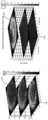
도 8은 자유형 반사기(802, 도 7)의 음향 맵에 대한 포물선 반사기(800, 도 1)의 음향 맵의 비교를 묘사한다. 도 8에 도시된 바와 같이, 자유형 반사기의 이용은 포물선 반사기를 이용하여 생성된 것과 비교할 때 음향 압력 핫스팟을 최소화하는 수단을 제공한다. 도 8의 포물선 반사기 부분(800)은 깊은 조직 깊이까지 지속되는 원주형 핫스팟(804)을 설명한다. 이들 음향 핫스팟은 조직 손상을 야기하여 조직 손상 및 치료 불편을 야기할 수 있다. 다르게, 자유형 반사기(802)의 음향 맵은 자유형 반사기 설계의 이용에 의해 달성된 깊이에서 원주형 핫스팟(806)의 효과적인 제거를 보여준다. 따라서, 자유형 반사기를 이용한 치료는 덜 아프고 부수적인 조직 손상에 대한 더 낮은 가능성을 갖는 치료를 제공한다.FIG. 8 depicts a comparison of the acoustic map of the parabolic reflector 800 ( FIG. 1 ) to that of the freeform reflector 802 ( FIG. 7 ). As shown in Figure 8, the use of freeform reflectors provides a means to minimize acoustic pressure hotspots compared to those produced using parabolic reflectors. The
B. 초점 안정화B. Focus stabilization
전기유압식 발전기에 의해 발생된 음향 파면 형성에 대한 논의는 2016년 7월 21일자로 출원된 발명의 명칭이 "개선된 전극 수명을 갖는 급속 펄스 전기유압식(EH) 충격파 발생기 장치"인 미국 가 특허 출원 번호 제 62/365,009 호에서 발견될 수 있고, 이는 전체적으로 참조로써 통합된다.For a discussion of acoustic wave front formation generated by electrohydraulic generators, see the U.S. Provisional Patent Application entitled “Rapid Pulse Electrohydraulic (EH) Shockwave Generator Device with Improved Electrode Life,” filed July 21, 2016. No. 62/365,009, which is incorporated by reference in its entirety.
개선된 음향 파면을 제공하기 위한 자유형 음향 반사기의 이용은 효과적인, 통증 없는 치료를 제공하는 것을 도울 수 있다. 그러나, 이러한 자유형 반사기의 설계는 챔버 내의 음향 소스의 안정적인 초점 위치로 최적화될 수 있다. 종래의 음향 파 발생기는 안정적인 초점 위치를 제공함에 있어 차선책이었으며, 이는 음향 적용을 위해 자유형 반사기를 설계하는데 어려움을 야기할 수 있다.The use of freeform acoustic reflectors to provide improved acoustic wavefronts can help provide effective, pain-free treatment. However, the design of these freeform reflectors can be optimized for a stable focal position of the acoustic source within the chamber. Conventional acoustic wave generators are suboptimal in providing stable focal positions, which can cause difficulties in designing freeform reflectors for acoustic applications.
챔버 내에서 안정적인 음향 초점 위치를 유지하기 위해, 특정 전극 갭 크기가 유지될 필요가 있을 뿐만 아니라, 반사기 챔버 내의 특정 전극 갭 위치가 일정하게 유지되어야 한다. 전극이 가변 레이트로 침식하기 때문에, 챔버 내에서 안정적인 갭 크기 및 갭 위치를 유지하는 것이 어렵다. 이 문제를 극복하기 위해, 각각의 전극은 끊임없이 조정되어야 한다.In order to maintain a stable acoustic focus position within the chamber, not only does a specific electrode gap size need to be maintained, but the specific electrode gap position within the reflector chamber must also be kept constant. Because the electrode erodes at a variable rate, it is difficult to maintain stable gap size and gap position within the chamber. To overcome this problem, each electrode must be constantly adjusted.
전극 중 하나 또는 둘 모두의 수동 조정은 음향 초점 위치 및 전극 갭 크기를 조정하는 하나의 잠재적 해결책이다. 이러한 수동 접근법은 예를 들면, 나사와 같은 메커니즘을 통해 전극(들)을 이동시키는 것과 관련될 수 있다. 이들 수동 접근법이 매우 느린 레이트로 음향 펄스를 생성하는 전기유압식 충격 파 발생기에서 수용될 수 있지만, 많은 수의 펄스를 신속하게 생성하는 전기유압식 충격 파 발생기는 전극을 빠르게 침식할 수 있고 따라서, 거의 일정한 조정, 전극의 수동 조정으로 충족시키기 어려운 요구조건을 요구한다.Manual adjustment of one or both electrodes is one potential solution to adjust the acoustic focus position and electrode gap size. This manual approach may involve moving the electrode(s) through a mechanism such as a screw, for example. Although these passive approaches are acceptable for electrohydraulic shock wave generators that generate acoustic pulses at very slow rates, electrohydraulic shock wave generators that generate large numbers of pulses quickly can erode the electrodes quickly and, therefore, have a nearly constant Adjustment requires requirements that are difficult to meet by manual adjustment of the electrodes.
부가적으로, 챔버 내에서 안정적인 갭 위치를 유지하기 위해, 어떤 조정 방법은 전극 사이의 특정 갭 크기를 유지해야 할 뿐만 아니라, 하우징 내에 특정 갭 위치를 유지해야 한다. 전극 크기가 안정적으로 유지되지만, 챔버 내의 갭 위치가 시프트되면, 결과적인 음향 파면은 안정적이지 않을 것이다. 결과적으로, 갭 크기 및 갭 위치(즉, 챔버 내의 초점 위치) 둘 모두를 유지하기 위해 2개의 전극의 조정이 요구된다. 이것을 상업적으로 실행가능한 방식으로 성취하기 위해, 2개의 전극의 수동 조정을 이용하는 것은 어렵고 비실용적이다.Additionally, to maintain a stable gap position within the chamber, any tuning method must not only maintain a specific gap size between the electrodes, but also maintain a specific gap position within the housing. If the electrode size remains stable, but the gap position within the chamber shifts, the resulting acoustic wavefront will not be stable. As a result, adjustment of the two electrodes is required to maintain both gap size and gap position (i.e., focus position within the chamber). To achieve this in a commercially viable manner, using manual adjustment of the two electrodes is difficult and impractical.
따라서, 자동화된 전극 조정 방법은 챔버 내의 위치 및 안정적인 전극 갭 크기를 제공하는데 도움이 될 것이다. 챔버 내에서 특정 전극 갭 크기 및 갭 위치를 유지하기 위한 종래의 자동화된 전극 조정 방식의 하나의 예는 US 2006/0036168로서 또한 공개되는 미국 특허 출원 번호 제 10/896,040 호('040 출원)에서 언급된다. '040 출원은 갭 제어 유닛이 2개의 서보모터 및 서보모터를 구동하기 위한 2개의 서보모터 구동기를 포함하는 자동 갭 조정을 갖는 전기유압식 충격 파 발생 시스템을 설명한다. 각각의 전극이 상이한 레이트로 침식되기 때문에, '040 출원'의 시스템에서 2개의 서보모터가 이용된다. 따라서, 특정 갭 위치를 유지하기 위해, 각각의 전극은 전극 갭 크기 및 갭 위치를 유지하기 위해 상이한 양으로 조정될 필요가 있다.Therefore, an automated electrode adjustment method would be helpful in providing stable electrode gap size and position within the chamber. One example of a conventional automated electrode adjustment scheme to maintain a particular electrode gap size and gap position within a chamber is referenced in US Patent Application No. 10/896,040 (filed '040), also published as US 2006/0036168. do. The '040 application describes an electrohydraulic shock wave generation system with automatic gap adjustment where the gap control unit includes two servomotors and two servomotor drivers for driving the servomotors. Since each electrode erodes at a different rate, two servomotors are used in the system of the '040 application'. Therefore, to maintain a specific gap position, each electrode needs to be adjusted a different amount to maintain the electrode gap size and gap position.
반사기 내에서 전극 갭 위치를 유지하기 위한 2개의 서보모터의 이용은 전극을 함유하는 전기유압식 장치에 비용 및 엔지니어링 복잡성을 부가한다. 결과적으로, 자동화된 조정가능한 전극을 갖는 단순한 음향 헤드를 포함하는 저비용의 상업적으로 실행가능한 전기유압식 충격파 발생 시스템을 구축하는 것은 실용적이지 않았다. 일회용인 구축 시스템은 유사하게 실용적이지 않고 상업적으로 실현가능하지 않았다.The use of two servomotors to maintain electrode gap position within the reflector adds cost and engineering complexity to electrohydraulic devices containing electrodes. As a result, it has not been practical to build a low-cost, commercially viable electrohydraulic shock wave generation system comprising a simple acoustic head with automated adjustable electrodes. Single-use construction systems were similarly impractical and not commercially feasible.
전기유압식 음향 파 발생기에서 이용된 2개의 전극이 상이한 레이트로 침식될 수 있지만, 이들 침식 레이트는 정의된 전력 레벨에서 상대적으로 유사해야 하며 침식 레이트의 비는 정의된 전력 레벨에서 상대적으로 유사해야 한다. 도 9는 각각의 별개의 전극에 대한 침식이 측정된 후, 325nF의 전력 레벨에서 일정 기간 동안 다수의 상이한 전기유압식 발생기를 구동시키는 실험 결과를 묘사한다. 결과는 모든 실험에서, 2개의 전극 모두 침식을 경험했으며 전극 쌍에서의 2개의 전극 모두 상이한 레이트의 침식을 경험했음을 나타낸다. 부가적으로, 결과는 2개의 전극에 대한 침식 레이트의 비와 마찬가지로 각각의 전극 쌍에서의 2개의 전극에 대한 침식 레이트가 비교적 일정하다는 것을 나타낸다. 도 9에 도시된 바와 같이, 평균 마모율은 2.62였다.Although two electrodes used in an electrohydraulic acoustic wave generator may erode at different rates, these erosion rates should be relatively similar at defined power levels and the ratio of erosion rates should be relatively similar at defined power levels. Figure 9 depicts the results of an experiment in which a number of different electrohydraulic generators were driven for a period of time at a power level of 325 nF, after which erosion was measured for each separate electrode. The results show that in all experiments, both electrodes experienced erosion and both electrodes in an electrode pair experienced erosion at different rates. Additionally, the results show that the erosion rates for the two electrodes in each electrode pair are relatively constant, as is the ratio of the erosion rates for the two electrodes. As shown in Figure 9, the average wear rate was 2.62.
이들 결과에 기초하여, 2개의 전극을 조정하는 것은 이제, 전기유압식 발생기 챔버 내에서 특정 갭 크기 및 초점 위치를 유지하기 위해 단일 서보모터(및 적절한 기어링)를 이용하여 달성될 수 있다. 이것은 상업적으로 실행가능한 전기유압식 발전기를 제작하기 위한 설계 및 비용을 단순화하고 자동화된 조정 전극을 갖는 단순하고, 저렴하며, 일회용 전기유압식 헤드를 생산하는 것을 가능하게 한다.Based on these results, steering the two electrodes can now be achieved using a single servomotor (and appropriate gearing) to maintain a specific gap size and focus position within the electrohydraulic generator chamber. This simplifies the design and cost for building commercially viable electrohydraulic generators and makes it possible to produce simple, inexpensive, disposable electrohydraulic heads with automated regulating electrodes.
예yes
도 10은 개선된 음향 파면을 가지는 음향 파의 전기유압식 발생을 위한 장치의 하나의 실시예의 단면도를 묘사한다. 도 10에 도시된 바와 같이, 음향 파의 전기유압식 발생을 위한 장치(1000)는: 챔버(1008) 및 충격파 유출구(1012)를 정의하는 하우징(1004); 챔버(1008)에 배치된 액체; 챔버(1008) 내의 음향 반사기(1020); 하나 이상의 스파크 갭(200)을 형성하기 위해 챔버(1008)에 배치되도록 구성된 복수의 전극(1016a, 1016b)(예로서, 스파크 헤드 또는 모듈에서의); 및 10Hz와 5MHz 사이의 레이트로 전압 펄스를 전극(1016a, 1016b)에 인가하도록 구성된 펄스 발생 시스템을 포함한다. 도시된 실시예에서, 음향 반사기(1020)는 자유형 반사기이거나 상기 자유형 반사기를 포함하는 반면에, 다른 실시예에서 음향 반사기는 포물선일 수 있다.Figure 10 depicts a cross-sectional view of one embodiment of a device for electrohydraulic generation of acoustic waves with improved acoustic wavefront. As shown in Figure 10, a
이 실시예에서, 안정화된 음향 파면은 음향 반사기로부터 일정한 초점 위치에 유지되는 복수의 전극으로부터 형성된 스파크 갭을 갖는 자유형 음향 반사기를 이용하여 성취된다.In this embodiment, a stabilized acoustic wavefront is achieved using a freeform acoustic reflector with a spark gap formed from a plurality of electrodes held at a constant focal position from the acoustic reflector.
본 실시예의 일부에서, 복수의(예로서, 2개의) 전극 사이의 스파크 갭은 스파크 갭을 반사기로부터 실질적으로 일정한 초점 위치에 유지시키기 위해 단일 서보모터를 이용하여 자동적으로 조정된다. 예를 들면, 도 10 내지 도 12에 도시된 실시예에서, 단일 서보모터는 전극 갭의 크기 및 위치가 실질적으로 일정하게 유지되는 방식으로 한 쌍의 전극을 이동시키기 위해 이용된다. 도 10은 충격 파를 전기유압식으로 발생시키기 위해 전원에 연결될 수 있는 장치 또는 프로브(1000)의 일부의 투시 단면도를 묘사한다. 도 11은 스파크 갭의 크기 및 위치를 유지하기 위해 전극의 조정을 허용하는 프로브(1000)의 부품의 사시도를 묘사하고; 도 12a 내지 도 12c는 스파크 갭의 유지를 도시하는 3개의 상이한 위치에서의 도 11의 부품을 묘사한다.In some of the present embodiments, the spark gap between the plurality (eg, two) electrodes is automatically adjusted using a single servomotor to maintain the spark gap at a substantially constant focal position away from the reflector. For example, in the embodiment shown in Figures 10-12, a single servomotor is used to move a pair of electrodes in such a way that the size and position of the electrode gap remain substantially constant. Figure 10 depicts a perspective cross-sectional view of a portion of a device or
도시된 실시예에서, 장치(1000)는 챔버(1008) 및 충격파 유출구(1012)를 정의하는 하우징(1004)을 포함하고, 챔버는 물과 같은 액체를 수용하도록(예로서, 상기 액체로 충진되도록) 구성된다. 도시된 바와 같이, 장치(1000)는 챔버(1008)(예로서, 챔버의 경계의 일부를 형성하는)에 배치된 음향 반사기(1020) 및 복수의 전극(1016a, 1016b)를 더 포함한다. 도시된 바와 같이, 전극(1016)은 크기(즉, 전극(1016a 및 1016b)의 단부 표면 사이의 거리) 및 위치를 가지는 하나 이상의 스파크 갭(200)을 형성하기 위해 챔버(1008)에 배치되도록 구성된다. 도시된 실시예에서, 반사기(1020)는 자유형 반사기이다.In the depicted embodiment,
도시된 실시예에서, 장치(1000)는 복수의 전극(1016a, 1016b)에 기계적으로 결합된 단일 서보모터(1024)를 포함하고, 스파크 갭(200)의 크기 및 위치를 실질적으로 일정하게 유지하기 위해 전극의 각각을 조정하도록 구성된다. 이 실시예에서, 서보모터(1024)는 리드 스크류(lead screw)(1036)의 회전이 푸셔(pusher)(1040)의 종방향 이동을 야기하도록, 쓰레드(threads)를 통해 셔틀 또는 푸셔(1040)에 결합되는 리드 스크류(1036)에 샤프트(1028)를 결합시키는 척(chuck) 또는 결합기(1032)를 갖는 출력 샤프트(1028)를 갖는다. 1차 전극(1016a)은 푸셔(1040)에 결합된다(예로서, 상기 푸셔에 의해 푸싱되도록 구성된다); 예를 들면, 도시된 실시예에서, 1차 전극 캐리어(1044)는 1차 전극(1016a)을 연장시키고/운반하며 도시된 바와 같이 푸셔(1040)로 연장한다. 다른 실시예에서, 전극 캐리어(1044) 및 1차 전극(116a)은 단일형일 수 있다(예로서, 단일 피스의 재료로 형성될 수 있다). 도시된 바와 같이, 스프레더 바(spreader bar)(1048)는 1차 전극 캐리어(1044)에 대해 고정되어 결합되고, 스프레더 바(1048)는 스프레더 바(1048)로부터 연장되고 2개의 각각의 피벗 암(1056a, 1056b)과 상호 작용하도록 구성된 2개의 푸셔 로드(pusher rods)(1052a, 1052b)를 운반한다. 도시된 바와 같이, 피벗 암(1056a, 1056b)은 각각, 푸셔 로드(1052a, 1052b)가 방향(1064)으로 전진함에 따라 각각의 피봇 포인트(1060a, 1060b)에서 하우징(1004)에 중추적으로 결합된다(예로서, 핀을 통해).In the depicted embodiment,
이 예에서, 2차 전극(1016b)은 2차 전극 캐리어(1064)에 결합된다(상기 2차 전극 캐리어에 의해). 도시된 바와 같이, 2차 전극 캐리어(1064)는 반전된 U-형상을 갖고, 하우징(1004)에 슬라이딩가능하게 결합된다(예로서, 슬롯 또는 트랙(1068)에 슬라이딩가능하게 배치된다). 부가적으로, 스프링 또는 다른 바이어싱 부재(biasing member)(도시되지 않음)는 1차 전극(1016a)으로부터 멀어지는 방향(1072)으로 2차 캐리어(1064) 및 2차 전극(1016b)을 바이어싱한다.In this example, secondary electrode 1016b is coupled to (by)
이 구성에서, 그리고 도 12a 내지 도 12c의 진행으로 도시된 바와 같이, 모터(1024)가 작동될 때, 샤프트(1028)는 리드 스크류(1036)를 회전시키고, 이는 차례로, 셔틀(1040), 1차 전극 캐리어(1044), 1차 전극(1016a), 스프레더 바(1048), 및 푸셔 로드(1052a, 1052b)를 방향(1072)으로 종방향으로 전진시킨다. 이들 부품이 전진됨에 따라, 푸셔 로드(1052a, 1052b)는 피벗 암(1056a, 1056b)의 각각의 제 1 단부(1076a, 1076b)와 접촉하고, 상기 피벗 암의 각각의 제 1 단부에 방향(1072)으로 힘을 가한다. 제 1 단부(1076a, 1076b) 상에 가해지는 상향(도 12a 내지 도 12c에 묘사된 방향인) 힘은 피벗 암(1056a, 1056b)으로 하여금 그들의 각각의 피봇 포인트(1060a, 1060b) 주위로 피봇되도록 하고, 피벗 암의 각각의 2차 단부(1080a, 1080b)를 하향으로 이동시켜 2차 전극(1016b)을 1차 전극(1016a) 쪽으로 이동시키기 위해 2차 전극 캐리어(1064) 상에 방향(1084)으로 힘을 가한다. 이러한 방식으로, 전극이 이용 중에 침식됨에 따라, 단일 서보모터는 전극(1016a, 1016b)의 단부 사이의 전극 갭의 크기 및 위치 둘 모두를 유지하기 위해 1차 전극(1016a)을 상향으로 그리고 2차 전극(1016b)을 하향으로 동시에 이동시킬 수 있다.In this configuration, and as shown in the progression of FIGS. 12A-12C, when the
도시된 실시예에서, 하우징(1004)은 또한, 미국 가 특허 출원 번호 제 62/365,009 호(상기 통합됨)에서 설명된 바와 같이, 외부 펄스 발생 시스템(도시되지 않음)으로부터 전압을 수신하도록 구성되는 회로 보드 어셈블리(1100)를 수용하고 전극 사이에 스파크를 발생시키며 그에 의해 충격파를 발생시키기 위해 1차 전극(1016a)에 및/또는 상기 1차 전극을 통해 전압 펄스를 전달한다. 도시된 실시예에서, 제어기(1104)는 제어기가 전극 사이의 스파크의 측정에 기초하여 모터(1024)를 제어할 수 있도록, 연결부(1108)를 통해 전극 중 하나 또는 둘 모두와, 그리고 연결부(1112)를 통해 모터(1024)와 전기 통신하여 결합된다(예로서, 도시된 바와 같은 회로 기판 어셈블리(1100), 또는 다른 실시예에서 직접적으로). 예를 들면, 일정한 전극 갭 크기 및 위치를 유지하기 위해, 폐쇄형 루프 제어는 전극을 전방으로 공급하고 갭(200)을 원하는 크기로 유지하도록 모터(1124)를 시그널링하기 위해 이용된다. 이 폐쇄형 루프 제어는 특정한 충전 전압에서 방전의 펄스 시간을 측정함으로써 수행될 수 있다. 방전의 특성은 전극 갭(200) 거리와 매우 밀접하게 상관되어 있다. 이들 특성을 측정함으로써, 폐쇄형 루프 제어는 이동하기 위해 모터(1024)를 시그널링함으로써 수행될 수 있고 그에 의해, 전극 사이의 갭을 유지하며, 결과적으로 방전의 원하는 전기적 특성을 유지한다. 일부 실시예에서, 제어기(1104)는 스파크 발생 시스템의 부품(예로서, 제어기(1104)에 대해 설명된 기능이 스파크 발생 시스템의 1차 방전 제어기에 의해 실행된 지시 또는 코드에 통합됨)이다. 예를 들면, 모터(1024)는 확장된 리드에 의해 모터 권선에 전기 펄스를 직접적으로 인가함으로써 스파크 발생 시스템의 메인 방전 제어기로부터 직접적으로 구동될 수 있다. 다른 실시예에서, 제어기(1104)는 별도의 조정 기능을 갖는 제 2 및/또는 독립 제어기이다. 예를 들면, 제어기(1104)는 하우징에 장착될 수 있고 스파크 발생 시스템의 1차 제어기 또는 상기 1차 제어기로부터 아날로그 또는 디지털 신호(예로서, 전기, 광학, 및/또는 이와 유사한 것)를 수신할 수 있다.In the depicted embodiment,
본 명세서에서 개시된 전기유압식 충격파 발생기는 개선된 음향 파면 균일성을 가지는 음향 파면을 생성한다. 하나의 실시예에 따르면, 이 개선된 음향 파면 균일성은 자유형 음향 반사기 및 단일 서보모터 전극 조정 시스템을 이용하는 전기유압식 발전기의 이용을 통해 성취된다. 결과적으로, 본 명세서에서 개시된 전기유압식 장치는 환자를 치료하기 위해 이용될 때 더 안전하고 더 편안한 음향 파 치료를 제공한다.The electrohydraulic shock wave generator disclosed herein generates an acoustic wavefront with improved acoustic wavefront uniformity. According to one embodiment, this improved acoustic wavefront uniformity is achieved through the use of an electrohydraulic generator utilizing a freeform acoustic reflector and a single servomotor electrode steering system. As a result, the electrohydraulic devices disclosed herein provide safer and more comfortable acoustic wave therapy when used to treat patients.
상기 명세서 및 예는 대표적인 실시예의 구조 및 이용의 설명을 제공한다. 특정 실시예가 특정 정도의 특수성을 갖고, 또는 하나 이상의 개개의 실시예를 참조하여 설명되었지만, 당업자는 본 발명의 범위로부터 벗어나지 않고 개시된 실시예에 대해 많은 변경을 할 수 있다. 이와 같이, 본 디바이스의 다양한 예시적인 실시예는 개시된 특정한 형태로 제한되도록 의도되지 않는다. 오히려, 그들은 청구항의 범위 내에 속하는 모든 수정 및 대안을 포함하며, 도시된 것이 아닌 실시예는 묘사된 실시예의 특징 중 일부 또는 모두를 포함할 수 있다. 예를 들면, 부품은 단일 구조로서 조합될 수 있다. 게다가, 적절한 경우, 상기 설명된 예 중 어떤 것의 양태는 비교가능하거나 상이한 속성을 가지는 또 다른 예를 형성하며 동일한 또는 상이한 문제를 다루기 위해 설명된 다른 예 중 어떤 것의 양태와 조합될 수 있다. 유사하게, 상기 설명된 이득 및 이점이 하나의 실시예와 관련될 수 있거나 몇몇 실시예와 관련될 수 있음이 이해될 것이다.The above specification and examples provide a description of the structure and use of representative embodiments. Although certain embodiments have been described with a certain degree of specificity or with reference to one or more individual embodiments, many changes may be made by those skilled in the art to the disclosed embodiments without departing from the scope of the invention. As such, the various illustrative embodiments of the present device are not intended to be limited to the specific forms disclosed. Rather, they include all modifications and alternatives that fall within the scope of the claims, and non-illustrated embodiments may include some or all of the features of the depicted embodiments. For example, parts can be combined into a single structure. Moreover, where appropriate, aspects of any of the examples described above may be combined with aspects of any of the other examples described to form another example with comparable or different properties and to address the same or different problems. Similarly, it will be appreciated that the benefits and advantages described above may relate to one embodiment or to several embodiments.
청구항은 이러한 제한이 각각 구절(들)("~를 위한 수단" 또는 "~를 위한 단계")을 이용하여 주어진 청구항에서 명확하게 인용되지 않는다면, 수단 플러스 또는 단계 플러스 기능 제한을 포함하는 것으로 해석되지 않아야 한다.Claims shall not be construed to include means plus or step plus functional limitations unless such limitations are specifically recited in a given claim using phrase(s) (“means for” or “steps for”) respectively. It shouldn't be.
참조 문헌References
[1] Delius, M., Jordan, M., 등. (1988). 충격 파의 생물학적 영향: 충격 파에 의한 개의 신장에서의 출혈--투여 레이트 의존성. Ultrasound in Med. & Biol., 14(8), 689-694.[1] Delius, M., Jordan, M., et al. (1988). Biological effects of shock waves: Shock wave-induced hemorrhage in the kidneys of dogs--dose rate dependence. Ultrasound in Med. & Biol., 14(8), 689-694.
[2] Gillitzer, R., 등. (2009). 저 주파수 체외 충격 파 쇄석술은 돼지 모델에서 신우결석 분해를 개선한다. BJU Int, 176, 1284-1288.[2] Gillitzer, R., et al. (2009). Low-frequency extracorporeal shock wave lithotripsy improves renal stone resolution in a porcine model. BJU Int, 176, 1284-1288.
[3] Madbouly, K., 등. (2005). 요로 결석에 대한 느린 대 빠른 충격 파 쇄석술 레이트: 전향적 무작위 연구. 비뇨기과 학회지, 173, 127-130.[3] Madbouly, K., et al. (2005). Slow versus fast shock wave lithotripsy rates for urinary tract stones: a prospective randomized study. Journal of Urology, 173, 127-130.
[4] Liu, Peng, 등. (2012). 균일한 원형 조명을 위한 LED 자유형 렌즈의 최적화된 설계. Journal of Zhejiang University Science C(Computer & Electron, 2012 13(12), 929-936.[4] Liu, Peng, et al. (2012). Optimized design of LED freeform lens for uniform circular illumination. Journal of Zhejiang University Science C(Computer & Electron, 2012 13(12), 929-936.
Claims (31)
Translated fromKorean액체를 수용하도록 구성된 챔버 및 충격파 유출구를 정의하는 하우징;
하나 이상의 스파크 갭(spark gap)을 형성하기 위해 상기 챔버에 배치되도록 구성된 복수의 전극;
상기 챔버에 배치된 음향 반사기; 및
상기 복수의 전극에 기계적으로 결합된 단일 서보모터(servomotor)를 포함하고;
상기 스파크 갭의 각각은 스파크 갭 크기 및 스파크 갭 위치를 갖고;
상기 단일 서보모터는 일관된 스파크 갭 크기 및 스파크 갭 위치를 유지하기 위해 상기 복수의 전극의 각각의 전극을 조정하도록 구성되는, 음향 파를 발생시키기 위한 장치.In a device for generating acoustic waves:
a housing defining a shock wave outlet and a chamber configured to contain a liquid;
a plurality of electrodes configured to be disposed in the chamber to form one or more spark gaps;
an acoustic reflector disposed in the chamber; and
comprising a single servomotor mechanically coupled to the plurality of electrodes;
Each of the spark gaps has a spark gap size and a spark gap position;
wherein the single servomotor is configured to adjust each electrode of the plurality of electrodes to maintain consistent spark gap size and spark gap position.
상기 음향 반사기는 자유형 음향 반사기를 포함하는, 음향 파를 발생시키기 위한 장치.According to claim 1,
A device for generating acoustic waves, wherein the acoustic reflector comprises a freeform acoustic reflector.
상기 복수의 전극은 제 1 전극 및 제 2 전극을 포함하고;
상기 단일 서보모터는 상기 제 1 전극 및 상기 제 2 전극에 기계적으로 결합되어, 상기 단일 서보모터의 액추에이션(actuation)은:
제 1 방향으로 상기 제 1 전극을 조정하고;
상기 제 1 방향과 반대인 제 2 방향으로 상기 제 2 전극을 조정하는, 음향 파를 발생시키기 위한 장치.According to claim 1,
The plurality of electrodes includes a first electrode and a second electrode;
The single servomotor is mechanically coupled to the first electrode and the second electrode, so that actuation of the single servomotor is:
adjusting the first electrode in a first direction;
A device for generating acoustic waves, wherein the second electrode is steered in a second direction opposite to the first direction.
상기 제 2 전극에 기계적으로 결합된 복수의 피벗 암(pivot arms)을 더 포함하는, 음향 파를 발생시키기 위한 장치.According to claim 3,
A device for generating acoustic waves, further comprising a plurality of pivot arms mechanically coupled to the second electrode.
상기 복수의 피벗 암은 상기 단일 서보모터가 작동되는 것에 응답하여 상기 제 1 전극 쪽으로 상기 제 2 전극을 전진시키도록 구성되는, 음향 파를 발생시키기 위한 장치.According to claim 4,
wherein the plurality of pivot arms are configured to advance the second electrode toward the first electrode in response to actuation of the single servomotor.
상기 스파크 갭을 일정한 길이로 유지하고 상기 복수의 전극을 이동시키도록 동작시키기 위해 폐쇄형 루프 제어를 통해 상기 단일 서보모터를 시그널링(signalling)하도록 구성된 제어기를 더 포함하는, 음향 파를 발생시키기 위한 장치.According to claim 1,
A device for generating acoustic waves, further comprising a controller configured to signal the single servomotor through closed loop control to maintain the spark gap at a constant length and operate the plurality of electrodes to move. .
상기 제어기는 또한, 상기 폐쇄형 루프 제어를 통해 상기 단일 서보모터를 시그널링하도록 구성되고, 상기 단일 서보모터를 시그널링하기 위해 상기 제어기는:
식별된 충전 전압에서 상기 복수의 전극의 방전의 펄스 시간을 측정하고;
상기 측정된 펄스 시간에 기초하여 이동시키기 위해 단일 서보모터를 시그널링하여, 그에 의해 상기 스파크 갭을 일관된 길이로 유지시키도록 구성되는, 음향 파를 발생시키기 위한 장치.According to claim 6,
The controller is also configured to signal the single servomotor through the closed loop control, and for signaling the single servomotor, the controller:
measure the pulse time of discharge of the plurality of electrodes at the identified charging voltage;
An apparatus for generating an acoustic wave, configured to signal a single servomotor to move based on the measured pulse time, thereby maintaining the spark gap at a consistent length.
전압 펄스들을 복수의 전극들에 전달하여 전극들 사이에 스파크를 발생시키고 그에의해 충격파들을 발생시키기 위해, 상기 복수의 전극에 결합되어, (i) 상기 하우징이 상기 펄스 발생 시스템에 대해 이동가능하고, (ii) 상기 펄스 발생 시스템이 상기 복수의 전극과 전기 통신하도록 구성된 펄스 발생 시스템을 더 포함하는, 음향 파를 발생시키기 위한 장치.According to claim 1,
Coupled to the plurality of electrodes for delivering voltage pulses to the plurality of electrodes to generate a spark between the electrodes and thereby generating shock waves, wherein (i) the housing is movable relative to the pulse generating system, (ii) a pulse generating system configured to electrically communicate with the plurality of electrodes.
액체를 수용하도록 구성된 챔버 및 충격파 유출구를 정의하는 하우징;
하나 이상의 스파크 갭을 형성하기 위해 상기 챔버에 배치되도록 구성된 복수의 전극; 및
상기 챔버에 배치된 자유형 음향 반사기를 포함하고,
하나 이상의 스파크 갭의 각각은 스파크 갭 크기 및 스파크 갭 위치를 갖는, 음향 파를 발생시키기 위한 장치.In a device for generating acoustic waves:
a housing defining a shock wave outlet and a chamber configured to contain a liquid;
a plurality of electrodes configured to be disposed in the chamber to form one or more spark gaps; and
comprising a free-form acoustic reflector disposed in the chamber,
A device for generating acoustic waves, wherein each of the one or more spark gaps has a spark gap size and a spark gap position.
상기 음향 반사기는 상기 하우징과 통합되는, 음향 파를 발생시키기 위한 장치.According to clause 9,
The device for generating acoustic waves, wherein the acoustic reflector is integrated with the housing.
음향 펄스의 원점, 환자의 타겟 영역, 및 안전 깊이를 정의하는 단계;
정의된 타겟 영역과 일치하는 에너지 분포를 유발할 수 있는 반사기 형상 및 상기 정의된 안전 깊이가 성취될 때까지 반사기 형상을 반복하는 단계;
최종 반사기 형상에 기초하여 에너지 밀도를 근사화하는 단계; 및
상기 최종 반사기 형상을 검증하는 단계를 포함하는, 자유형 음향 반사기를 설계하기 위한 방법.In a method for designing a freeform acoustic reflector:
defining the origin of the acoustic pulse, target area of the patient, and safety depth;
repeating the reflector shape until the defined safety depth and a reflector shape capable of resulting in an energy distribution consistent with the defined target area are achieved;
approximating the energy density based on the final reflector shape; and
A method for designing a freeform acoustic reflector, comprising verifying the final reflector shape.
음향 펄스의 원점을 정의하는 단계는 복수의 전극이 전기유압식 음향 파 발생기에서 위치되는 위치를 정의하는 단계를 더 포함하는, 자유형 음향 반사기를 설계하기 위한 방법.According to claim 11,
A method for designing a freeform acoustic reflector, wherein defining the origin of the acoustic pulse further comprises defining positions at which the plurality of electrodes are located in the electrohydraulic acoustic wave generator.
환자의 타겟 영역을 정의하는 단계는 균일한 압력 밀도를 전달할 조직 깊이를 지정하는 단계를 더 포함하는, 자유형 음향 반사기를 설계하기 위한 방법.According to claim 11,
A method for designing a freeform acoustic reflector, wherein defining a target area of the patient further comprises specifying a tissue depth that will deliver a uniform pressure density.
안전 깊이를 정의하는 단계는 집속되지 않은 음향 파가 50%만큼 소멸되는 상기 환자의 조직에서 깊이를 결정하는 단계를 더 포함하는, 자유형 음향 반사기를 설계하기 위한 방법.According to claim 11,
Wherein defining a safe depth further comprises determining a depth in the patient's tissue at which unfocused acoustic waves are extinguished by 50%.
반사기 형상을 반복하는 단계는 스플라인 보간법(spline interpolation)을 이용하는 단계를 더 포함하는, 자유형 음향 반사기를 설계하기 위한 방법.According to claim 11,
A method for designing a freeform acoustic reflector, wherein repeating the reflector shape further comprises using spline interpolation.
에너지 밀도를 근사화하는 단계는 광선 추적을 수행하는 단계를 더 포함하는, 자유형 음향 반사기를 설계하기 위한 방법.According to claim 11,
A method for designing a freeform acoustic reflector, wherein approximating the energy density further comprises performing ray tracing.
상기 최종 반사기 형상을 검증하는 단계는 유한 요소법(finite element method; FEM) 시뮬레이션을 이용하는 단계를 더 포함하는, 자유형 음향 반사기를 설계하기 위한 방법.According to claim 11,
Wherein verifying the final reflector shape further comprises using finite element method (FEM) simulation.
액체를 수용하도록 구성된 챔버 및 충격파 유출구를 정의하는 하우징;
스파크 갭을 형성하기 위해 상기 챔버에 배치되도록 구성된 복수의 전극; 및
상기 챔버에 배치된 자유형 음향 반사기를 포함하는, 음향 파를 발생시키기 위한 장치.In a device for generating acoustic waves:
a housing defining a shock wave outlet and a chamber configured to contain a liquid;
a plurality of electrodes configured to be disposed in the chamber to form a spark gap; and
A device for generating acoustic waves, comprising a free-form acoustic reflector disposed in the chamber.
상기 자유형 음향 반사기는 하우징과 통합되는, 음향 파를 발생시키기 위한 장치.According to claim 18,
A device for generating acoustic waves, wherein the freeform acoustic reflector is integrated with the housing.
상기 복수의 전극은 스파크 갭에서 스파크를 발생시키도록 구성되고,
상기 챔버가 액체로 충진되고 상기 복수의 전극이 스파크를 발생시킬 때, 복수의 음향 파가 상기 자유형 음향 반사기에서 반사되어 파동 경로를 따라 상기 하우징으로부터 벗어나고,
상기 자유형 음향 반사기는 상기 복수의 음향 파를 반사하여 상기 음향 파가 타겟 영역에서 균일한 집속되지 않은 압력 밀도를 가지도록 구성되고,
상기 타겟 영역은 제 1 깊이만큼 상기 하우징으로부터 이격된 파동 경로에 따른 영역인, 음향 파를 발생시키기 위한 장치.According to claim 18,
The plurality of electrodes are configured to generate sparks in the spark gap,
When the chamber is filled with liquid and the plurality of electrodes generate a spark, a plurality of acoustic waves are reflected from the freeform acoustic reflector and escape the housing along a wave path,
The freeform acoustic reflector is configured to reflect the plurality of acoustic waves so that the acoustic waves have a uniform non-focused pressure density in the target area,
The target area is an area along the wave path spaced from the housing by a first depth.
상기 자유형 음향 반사기는 음향 파를 반사하여 음향 파가 타겟 영역에서 10% 미만인 평균 피크 압력 변동을 가지도록 구성되는, 음향 파를 발생시키기 위한 장치.According to claim 20,
The freeform acoustic reflector is configured to reflect the acoustic wave so that the acoustic wave has an average peak pressure variation of less than 10% in the target area.
상기 자유형 음향 반사기는 음향 파를 반사하여 음향 파가 타겟 영역에서 5% 미만인 평균 피크 압력 변동을 가지도록 구성되는, 음향 파를 발생시키기 위한 장치.According to claim 20,
The freeform acoustic reflector is configured to reflect the acoustic wave so that the acoustic wave has an average peak pressure variation of less than 5% in the target area.
상기 제 1 깊이는 10mm 미만인, 음향 파를 발생시키기 위한 장치.According to claim 20,
A device for generating acoustic waves, wherein the first depth is less than 10 mm.
상기 제 1 깊이는 30mm 미만인, 음향 파를 발생시키기 위한 장치.According to claim 20,
A device for generating acoustic waves, wherein the first depth is less than 30 mm.
상기 제 1 깊이는 50mm 미만인, 음향 파를 발생시키기 위한 장치.According to claim 20,
A device for generating acoustic waves, wherein the first depth is less than 50 mm.
상기 장치는 파동 경로에 따른 복수의 음향 파를 발생시켜, 복수의 음향 파가 제 1 깊이에서 제 1 평균 피크 압력을 가지고, 상기 제 1 깊이보다 상기 하우징으로부터 더 먼 제 2 깊이에서 제 2 평균 피크 압력을 가지도록 구성되고,
상기 제 2 평균 피크 압력은 상기 제 1 평균 피크 압력의 50 퍼센트 미만인, 음향 파를 발생시키기 위한 장치.According to claim 18,
The device generates a plurality of acoustic waves along a wave path, such that the plurality of acoustic waves have a first average peak pressure at a first depth and a second average peak at a second depth further from the housing than the first depth. It is configured to have pressure,
wherein the second average peak pressure is less than 50 percent of the first average peak pressure.
상기 제 2 깊이는 상기 제 1 깊이의 700%이하인, 음향 파를 발생시키기 위한 장치.According to claim 26,
The second depth is less than or equal to 700% of the first depth.
상기 음향 파는 상기 제 1 깊이에서 10% 미만인 평균 피크 압력 변동을 가지는, 음향 파를 발생시키기 위한 장치.According to claim 26,
wherein the acoustic waves have an average peak pressure variation of less than 10% at the first depth.
상기 제 1 깊이는 5mm 미만인, 음향 파를 발생시키기 위한 장치.According to claim 26,
A device for generating acoustic waves, wherein the first depth is less than 5 mm.
상기 제 1 깊이는 상기 하우징의 유출구로부터 2mm에서 5% 이내에 있고,
상기 음향 파의 제 1 평균 피크 압력은 4.5MPa보다 큰, 음향 파를 발생시키기 위한 장치.According to claim 26,
the first depth is within 2 mm to 5% of the outlet of the housing,
A device for generating acoustic waves, wherein the first average peak pressure of the acoustic waves is greater than 4.5 MPa.
상기 제 2 깊이는 상기 하우징의 유출구로부터 30mm에서 5% 이내에 있고,
상기 음향 파의 제 2 평균 피크 압력은 3.0MPa보다 작은, 음향 파를 발생시키기 위한 장치.
According to claim 30,
the second depth is within 5% of 30 mm from the outlet of the housing,
A device for generating acoustic waves, wherein the second average peak pressure of the acoustic waves is less than 3.0 MPa.
Priority Applications (1)
| Application Number | Priority Date | Filing Date | Title |
|---|---|---|---|
| KR1020237032334AKR20230138057A (en) | 2017-01-17 | 2018-01-17 | Rapid pulse electrohydraulic (eh) shockwave generator apparatus with improved acoustic wavefronts |
Applications Claiming Priority (3)
| Application Number | Priority Date | Filing Date | Title |
|---|---|---|---|
| US201762447191P | 2017-01-17 | 2017-01-17 | |
| US62/447,191 | 2017-01-17 | ||
| PCT/US2018/014053WO2018136514A1 (en) | 2017-01-17 | 2018-01-17 | Rapid pulse electrohydraulic (eh) shockwave generator apparatus with improved acoustic wavefronts |
Related Child Applications (1)
| Application Number | Title | Priority Date | Filing Date |
|---|---|---|---|
| KR1020237032334ADivisionKR20230138057A (en) | 2017-01-17 | 2018-01-17 | Rapid pulse electrohydraulic (eh) shockwave generator apparatus with improved acoustic wavefronts |
Publications (2)
| Publication Number | Publication Date |
|---|---|
| KR20190108137A KR20190108137A (en) | 2019-09-23 |
| KR102583380B1true KR102583380B1 (en) | 2023-10-04 |
Family
ID=62908811
Family Applications (3)
| Application Number | Title | Priority Date | Filing Date |
|---|---|---|---|
| KR1020197024022AActiveKR102583380B1 (en) | 2017-01-17 | 2018-01-17 | Fast pulse electrohydraulic (EH) shock wave generator device with improved acoustic wavefront |
| KR1020247043308APendingKR20250007700A (en) | 2017-01-17 | 2018-01-17 | Rapid pulse electrohydraulic (eh) shockwave generator apparatus with improved acoustic wavefronts |
| KR1020237032334AAbandonedKR20230138057A (en) | 2017-01-17 | 2018-01-17 | Rapid pulse electrohydraulic (eh) shockwave generator apparatus with improved acoustic wavefronts |
Family Applications After (2)
| Application Number | Title | Priority Date | Filing Date |
|---|---|---|---|
| KR1020247043308APendingKR20250007700A (en) | 2017-01-17 | 2018-01-17 | Rapid pulse electrohydraulic (eh) shockwave generator apparatus with improved acoustic wavefronts |
| KR1020237032334AAbandonedKR20230138057A (en) | 2017-01-17 | 2018-01-17 | Rapid pulse electrohydraulic (eh) shockwave generator apparatus with improved acoustic wavefronts |
Country Status (9)
| Country | Link |
|---|---|
| US (1) | US20200046391A1 (en) |
| EP (1) | EP3570761A4 (en) |
| JP (3) | JP7458186B2 (en) |
| KR (3) | KR102583380B1 (en) |
| CN (2) | CN116898528A (en) |
| BR (1) | BR112019014656A2 (en) |
| CA (1) | CA3050008A1 (en) |
| MX (2) | MX2019008552A (en) |
| WO (1) | WO2018136514A1 (en) |
Families Citing this family (13)
| Publication number | Priority date | Publication date | Assignee | Title |
|---|---|---|---|---|
| AU2011207601B2 (en) | 2010-01-19 | 2014-10-02 | The Board Of Regents Of The University Of Texas System | Apparatuses and systems for generating high-frequency shockwaves, and methods of use |
| AR087170A1 (en) | 2011-07-15 | 2014-02-26 | Univ Texas | APPARATUS FOR GENERATING THERAPEUTIC SHOCK WAVES AND ITS APPLICATIONS |
| US12220380B2 (en) | 2015-09-30 | 2025-02-11 | Btl Medical Solutions A.S. | Methods and devices for tissue treatment using mechanical stimulation and electromagnetic field |
| US11484724B2 (en) | 2015-09-30 | 2022-11-01 | Btl Medical Solutions A.S. | Methods and devices for tissue treatment using mechanical stimulation and electromagnetic field |
| EP3432985A4 (en) | 2016-03-23 | 2019-11-20 | Soliton, Inc. | SYSTEM AND METHOD FOR PULSED ACOUSTIC WAVE SKIN CLEANING |
| TW202448390A (en) | 2016-07-21 | 2024-12-16 | 美商席利通公司 | Rapid pulse electrohydraulic (eh) shockwave generator apparatus with improved electrode lifetime |
| EP3582686A4 (en) | 2017-02-19 | 2020-12-02 | Soliton, Inc. | SELECTIVE LASER INDUCED OPTICAL BREAKTHROUGH IN A BIOLOGICAL MEDIUM |
| WO2020023412A1 (en) | 2018-07-23 | 2020-01-30 | Nc8, Inc. | Cellulite treatment system and methods |
| MX2021000901A (en) | 2018-07-23 | 2021-06-18 | Revelle Aesthetics Inc | Cellulite treatment system and methods. |
| US11980388B2 (en) | 2018-07-23 | 2024-05-14 | Revelle Aesthetics, Inc. | Cellulite treatment apparatus |
| US12097162B2 (en) | 2019-04-03 | 2024-09-24 | Soliton, Inc. | Systems, devices, and methods of treating tissue and cellulite by non-invasive acoustic subcision |
| EP4458283A1 (en)* | 2023-05-03 | 2024-11-06 | Likamed GmbH | Shock wave condensing and focusing device, use of a device for deflecting and focusing shock waves, method for focusing and deflecting a shock wave |
| CN116687514B (en)* | 2023-05-26 | 2024-07-02 | 索诺利(厦门)医疗科技有限公司 | High-energy emitter capable of stably outputting energy for extracorporeal lithotripter |
Citations (5)
| Publication number | Priority date | Publication date | Assignee | Title |
|---|---|---|---|---|
| US20060036168A1 (en)* | 2004-07-22 | 2006-02-16 | Shen-Min Liang | Electrohydraulic shock wave-generating system with automatic gap adjustment |
| US20070219760A1 (en) | 2006-03-17 | 2007-09-20 | Tsinghua University | System and method for designing a free form reflector |
| US20100208467A1 (en) | 2007-10-12 | 2010-08-19 | Oliver Dross | Free-form reflector array transforming a collimated beam into prescribed illumination |
| US20120157892A1 (en)* | 2007-04-20 | 2012-06-21 | Mts Europe Gmbh | Apparatus and Method for Clearance Calibration of Shock Wave Electrodes |
| US20160067139A1 (en) | 2012-06-22 | 2016-03-10 | Sanuwave, Inc. | Shock Wave Electrodes with Fluid Holes |
Family Cites Families (29)
| Publication number | Priority date | Publication date | Assignee | Title |
|---|---|---|---|---|
| JPS57138544A (en)* | 1981-02-18 | 1982-08-26 | Inoue Japax Res Inc | Feeder for electrical discharge machining |
| US5204820A (en) | 1987-03-11 | 1993-04-20 | Eastman Kodak Company | Method of producing an optically effective arrangement in particular for application with a vehicular headlight |
| CS270064B1 (en)* | 1988-07-01 | 1990-06-13 | Pavel Ing Csc Sunka | Method of surge generator's spark gap's points regulation for non-invasive lithotrity and device for realization of this method |
| DE3904049C1 (en)* | 1989-02-10 | 1990-06-28 | Storz Medical Ag, Kreuzlingen, Ch | |
| US5152767A (en)* | 1990-11-23 | 1992-10-06 | Northgate Technologies, Inc. | Invasive lithotripter with focused shockwave |
| EP0519112B1 (en)* | 1991-06-21 | 1996-03-13 | Tetsuhiro Kano | Reflector and method of generating a reflector shape |
| US5529572A (en) | 1992-01-24 | 1996-06-25 | Medispec Ltd. | Method and apparatus particularly useful for treating osteoporosis |
| FR2733062B1 (en) | 1995-04-13 | 1997-06-27 | Thomson Multimedia Sa | PROJECTION SYSTEM COMPRISING A REFLECTOR AND A FREE SURFACE FIELD LENS |
| US5675495A (en) | 1995-05-18 | 1997-10-07 | Hella K.G. Hueck & Co. | Process for the design of free form reflectors which accounts for manufacturing tolerances |
| EP0911804B1 (en)* | 1997-10-24 | 2007-05-09 | MTS Europe GmbH | Method for the automatic adjustment of the distance between the electrodes of a spark gap in electrohydraulic shock wave generators |
| JP4075973B2 (en)* | 1998-12-04 | 2008-04-16 | スタンレー電気株式会社 | Reflector manufacturing method and lamp |
| US6755796B2 (en)* | 1999-02-07 | 2004-06-29 | Medispec Ltd. | Pressure-pulse therapy apparatus |
| FR2799111B1 (en)* | 1999-10-01 | 2002-06-28 | Internova Int Innovation | LITHOTRITING APPARATUS |
| AU2002214220A1 (en) | 2000-10-29 | 2002-05-06 | Medispec Ltd. | Pressure-pulse therapy device for treatment of deposits |
| US8257282B2 (en)* | 2004-02-19 | 2012-09-04 | General Patent, Llc | Pressure pulse/shock wave apparatus for generating waves having plane, nearly plane, convergent off target or divergent characteristics |
| US8162859B2 (en) | 2005-06-09 | 2012-04-24 | General Patent , LLC | Shock wave treatment device and method of use |
| EP3391844A1 (en)* | 2007-04-19 | 2018-10-24 | Miramar Labs, Inc. | Apparatus for reducing sweat production |
| JP2010170856A (en)* | 2009-01-23 | 2010-08-05 | Seiko Epson Corp | Reflector, optical-source device, and projector |
| JP2013508180A (en)* | 2009-10-21 | 2013-03-07 | パーフェクト ポイント イーディーエム コーポレイション | Spark gap control for electrical discharge machine |
| AU2011207601B2 (en)* | 2010-01-19 | 2014-10-02 | The Board Of Regents Of The University Of Texas System | Apparatuses and systems for generating high-frequency shockwaves, and methods of use |
| WO2011126580A2 (en)* | 2010-04-09 | 2011-10-13 | Minnow Medical, Inc. | Power generating and control apparatus for the treatment of tissue |
| AR087170A1 (en) | 2011-07-15 | 2014-02-26 | Univ Texas | APPARATUS FOR GENERATING THERAPEUTIC SHOCK WAVES AND ITS APPLICATIONS |
| US9333000B2 (en)* | 2012-09-13 | 2016-05-10 | Shockwave Medical, Inc. | Shockwave catheter system with energy control |
| US10182838B2 (en)* | 2012-12-26 | 2019-01-22 | Tohoku University | Shock wave focusing device, shock wave generation apparatus, and shock wave ablation system |
| US10835767B2 (en)* | 2013-03-08 | 2020-11-17 | Board Of Regents, The University Of Texas System | Rapid pulse electrohydraulic (EH) shockwave generator apparatus and methods for medical and cosmetic treatments |
| US9254170B2 (en) | 2013-03-13 | 2016-02-09 | Ethicon Endo-Surgery, Inc. | Electrosurgical device with disposable shaft having modular subassembly |
| US20150224345A1 (en)* | 2014-02-13 | 2015-08-13 | John Warlick | Acoustic shock wave therapeutic methods |
| WO2016095876A1 (en)* | 2014-12-19 | 2016-06-23 | Univerzita Karlova V Praze | Shockwave applicator and a shockwave application system |
| WO2018005999A1 (en) | 2016-07-01 | 2018-01-04 | Pemko Manufacturing Co. | Apparatus for minimizing closing force of a door |
- 2018
- 2018-01-17KRKR1020197024022Apatent/KR102583380B1/enactiveActive
- 2018-01-17WOPCT/US2018/014053patent/WO2018136514A1/ennot_activeCeased
- 2018-01-17MXMX2019008552Apatent/MX2019008552A/enunknown
- 2018-01-17KRKR1020247043308Apatent/KR20250007700A/enactivePending
- 2018-01-17KRKR1020237032334Apatent/KR20230138057A/ennot_activeAbandoned
- 2018-01-17CACA3050008Apatent/CA3050008A1/enactivePending
- 2018-01-17JPJP2019538392Apatent/JP7458186B2/enactiveActive
- 2018-01-17CNCN202310880516.9Apatent/CN116898528A/enactivePending
- 2018-01-17BRBR112019014656Apatent/BR112019014656A2/ennot_activeApplication Discontinuation
- 2018-01-17CNCN201880011928.6Apatent/CN110573096B/enactiveActive
- 2018-01-17EPEP18742001.3Apatent/EP3570761A4/enactivePending
- 2018-01-17USUS16/478,611patent/US20200046391A1/enactivePending
- 2019
- 2019-07-17MXMX2024004607Apatent/MX2024004607A/enunknown
- 2023
- 2023-01-04JPJP2023000156Apatent/JP7625019B2/enactiveActive
- 2024
- 2024-08-30JPJP2024148314Apatent/JP2024167345A/ennot_activeAbandoned
Patent Citations (5)
| Publication number | Priority date | Publication date | Assignee | Title |
|---|---|---|---|---|
| US20060036168A1 (en)* | 2004-07-22 | 2006-02-16 | Shen-Min Liang | Electrohydraulic shock wave-generating system with automatic gap adjustment |
| US20070219760A1 (en) | 2006-03-17 | 2007-09-20 | Tsinghua University | System and method for designing a free form reflector |
| US20120157892A1 (en)* | 2007-04-20 | 2012-06-21 | Mts Europe Gmbh | Apparatus and Method for Clearance Calibration of Shock Wave Electrodes |
| US20100208467A1 (en) | 2007-10-12 | 2010-08-19 | Oliver Dross | Free-form reflector array transforming a collimated beam into prescribed illumination |
| US20160067139A1 (en) | 2012-06-22 | 2016-03-10 | Sanuwave, Inc. | Shock Wave Electrodes with Fluid Holes |
Also Published As
| Publication number | Publication date |
|---|---|
| JP7458186B2 (en) | 2024-03-29 |
| MX2024004607A (en) | 2024-04-30 |
| JP2020513937A (en) | 2020-05-21 |
| EP3570761A4 (en) | 2021-02-17 |
| EP3570761A1 (en) | 2019-11-27 |
| CA3050008A1 (en) | 2018-07-26 |
| US20200046391A1 (en) | 2020-02-13 |
| JP7625019B2 (en) | 2025-01-31 |
| JP2023036925A (en) | 2023-03-14 |
| MX2019008552A (en) | 2019-12-19 |
| CN116898528A (en) | 2023-10-20 |
| CN110573096A (en) | 2019-12-13 |
| KR20190108137A (en) | 2019-09-23 |
| JP2024167345A (en) | 2024-12-03 |
| WO2018136514A1 (en) | 2018-07-26 |
| KR20250007700A (en) | 2025-01-14 |
| KR20230138057A (en) | 2023-10-05 |
| BR112019014656A2 (en) | 2020-05-26 |
| CN110573096B (en) | 2023-07-28 |
Similar Documents
| Publication | Publication Date | Title |
|---|---|---|
| KR102583380B1 (en) | Fast pulse electrohydraulic (EH) shock wave generator device with improved acoustic wavefront | |
| US20210069529A1 (en) | Rapid pulse electrohydraulic (eh) shockwave generator apparatus and methods for medical and cosmetic treatments | |
| TWI838508B (en) | Acoustic subcision device and method of using acoustic subcision device | |
| US8257282B2 (en) | Pressure pulse/shock wave apparatus for generating waves having plane, nearly plane, convergent off target or divergent characteristics | |
| KR20240112938A (en) | Rapid pulse electrohydraulic (eh) shockwave generator apparatus with improved electrode lifetime | |
| US12402898B2 (en) | Acoustic shock wave or pressure pulse treatment for proptosis or exophthalmos | |
| HK40016115A (en) | Rapid pulse electrohydraulic (eh) shockwave generator apparatus with improved acoustic wavefronts | |
| US20060100549A1 (en) | Pressure pulse/shock wave apparatus for generating waves having nearly plane or divergent characteristics | |
| KR20200135426A (en) | Low energy acoustic pulse device and method | |
| TWI899882B (en) | Acoustic subcision device, acoustic subcision system, method of using acoustic subcision device, and vacuum system | |
| JP7753098B2 (en) | Systems, devices, and methods for treating tissue and cellulite with non-invasive acoustic subcision | |
| RU184163U1 (en) | Device for photoprocessing of human biological tissues | |
| US20210393476A1 (en) | Improved acoustic shock wave therapeutic methods |
Legal Events
| Date | Code | Title | Description |
|---|---|---|---|
| PA0105 | International application | St.27 status event code:A-0-1-A10-A15-nap-PA0105 | |
| PG1501 | Laying open of application | St.27 status event code:A-1-1-Q10-Q12-nap-PG1501 | |
| A201 | Request for examination | ||
| PA0201 | Request for examination | St.27 status event code:A-1-2-D10-D11-exm-PA0201 | |
| E902 | Notification of reason for refusal | ||
| PE0902 | Notice of grounds for rejection | St.27 status event code:A-1-2-D10-D21-exm-PE0902 | |
| T11-X000 | Administrative time limit extension requested | St.27 status event code:U-3-3-T10-T11-oth-X000 | |
| P11-X000 | Amendment of application requested | St.27 status event code:A-2-2-P10-P11-nap-X000 | |
| P13-X000 | Application amended | St.27 status event code:A-2-2-P10-P13-nap-X000 | |
| E701 | Decision to grant or registration of patent right | ||
| PE0701 | Decision of registration | St.27 status event code:A-1-2-D10-D22-exm-PE0701 | |
| PA0104 | Divisional application for international application | St.27 status event code:A-0-1-A10-A18-div-PA0104 St.27 status event code:A-0-1-A10-A16-div-PA0104 | |
| PR0701 | Registration of establishment | St.27 status event code:A-2-4-F10-F11-exm-PR0701 | |
| PR1002 | Payment of registration fee | St.27 status event code:A-2-2-U10-U12-oth-PR1002 Fee payment year number:1 | |
| PG1601 | Publication of registration | St.27 status event code:A-4-4-Q10-Q13-nap-PG1601 |