KR102580490B1 - Fluid media monitoring device - Google Patents
Fluid media monitoring deviceDownload PDFInfo
- Publication number
- KR102580490B1 KR102580490B1KR1020217016065AKR20217016065AKR102580490B1KR 102580490 B1KR102580490 B1KR 102580490B1KR 1020217016065 AKR1020217016065 AKR 1020217016065AKR 20217016065 AKR20217016065 AKR 20217016065AKR 102580490 B1KR102580490 B1KR 102580490B1
- Authority
- KR
- South Korea
- Prior art keywords
- unit
- light
- ultraviolet rays
- collimator
- flow cell
- Prior art date
- Legal status (The legal status is an assumption and is not a legal conclusion. Google has not performed a legal analysis and makes no representation as to the accuracy of the status listed.)
- Active
Links
Images

Classifications
- G—PHYSICS
- G01—MEASURING; TESTING
- G01N—INVESTIGATING OR ANALYSING MATERIALS BY DETERMINING THEIR CHEMICAL OR PHYSICAL PROPERTIES
- G01N15/00—Investigating characteristics of particles; Investigating permeability, pore-volume or surface-area of porous materials
- G01N15/06—Investigating concentration of particle suspensions
- G—PHYSICS
- G01—MEASURING; TESTING
- G01N—INVESTIGATING OR ANALYSING MATERIALS BY DETERMINING THEIR CHEMICAL OR PHYSICAL PROPERTIES
- G01N21/00—Investigating or analysing materials by the use of optical means, i.e. using sub-millimetre waves, infrared, visible or ultraviolet light
- G01N21/17—Systems in which incident light is modified in accordance with the properties of the material investigated
- G01N21/25—Colour; Spectral properties, i.e. comparison of effect of material on the light at two or more different wavelengths or wavelength bands
- G01N21/31—Investigating relative effect of material at wavelengths characteristic of specific elements or molecules, e.g. atomic absorption spectrometry
- G01N21/33—Investigating relative effect of material at wavelengths characteristic of specific elements or molecules, e.g. atomic absorption spectrometry using ultraviolet light
- G—PHYSICS
- G01—MEASURING; TESTING
- G01J—MEASUREMENT OF INTENSITY, VELOCITY, SPECTRAL CONTENT, POLARISATION, PHASE OR PULSE CHARACTERISTICS OF INFRARED, VISIBLE OR ULTRAVIOLET LIGHT; COLORIMETRY; RADIATION PYROMETRY
- G01J3/00—Spectrometry; Spectrophotometry; Monochromators; Measuring colours
- G01J3/02—Details
- G01J3/0205—Optical elements not provided otherwise, e.g. optical manifolds, diffusers, windows
- G01J3/0208—Optical elements not provided otherwise, e.g. optical manifolds, diffusers, windows using focussing or collimating elements, e.g. lenses or mirrors; performing aberration correction
- G—PHYSICS
- G01—MEASURING; TESTING
- G01J—MEASUREMENT OF INTENSITY, VELOCITY, SPECTRAL CONTENT, POLARISATION, PHASE OR PULSE CHARACTERISTICS OF INFRARED, VISIBLE OR ULTRAVIOLET LIGHT; COLORIMETRY; RADIATION PYROMETRY
- G01J3/00—Spectrometry; Spectrophotometry; Monochromators; Measuring colours
- G01J3/02—Details
- G01J3/0205—Optical elements not provided otherwise, e.g. optical manifolds, diffusers, windows
- G01J3/0218—Optical elements not provided otherwise, e.g. optical manifolds, diffusers, windows using optical fibers
- G—PHYSICS
- G01—MEASURING; TESTING
- G01J—MEASUREMENT OF INTENSITY, VELOCITY, SPECTRAL CONTENT, POLARISATION, PHASE OR PULSE CHARACTERISTICS OF INFRARED, VISIBLE OR ULTRAVIOLET LIGHT; COLORIMETRY; RADIATION PYROMETRY
- G01J3/00—Spectrometry; Spectrophotometry; Monochromators; Measuring colours
- G01J3/02—Details
- G01J3/06—Scanning arrangements arrangements for order-selection
- G—PHYSICS
- G01—MEASURING; TESTING
- G01J—MEASUREMENT OF INTENSITY, VELOCITY, SPECTRAL CONTENT, POLARISATION, PHASE OR PULSE CHARACTERISTICS OF INFRARED, VISIBLE OR ULTRAVIOLET LIGHT; COLORIMETRY; RADIATION PYROMETRY
- G01J3/00—Spectrometry; Spectrophotometry; Monochromators; Measuring colours
- G01J3/28—Investigating the spectrum
- G01J3/30—Measuring the intensity of spectral lines directly on the spectrum itself
- G01J3/32—Investigating bands of a spectrum in sequence by a single detector
- G—PHYSICS
- G01—MEASURING; TESTING
- G01J—MEASUREMENT OF INTENSITY, VELOCITY, SPECTRAL CONTENT, POLARISATION, PHASE OR PULSE CHARACTERISTICS OF INFRARED, VISIBLE OR ULTRAVIOLET LIGHT; COLORIMETRY; RADIATION PYROMETRY
- G01J3/00—Spectrometry; Spectrophotometry; Monochromators; Measuring colours
- G01J3/28—Investigating the spectrum
- G01J3/42—Absorption spectrometry; Double beam spectrometry; Flicker spectrometry; Reflection spectrometry
- G—PHYSICS
- G01—MEASURING; TESTING
- G01N—INVESTIGATING OR ANALYSING MATERIALS BY DETERMINING THEIR CHEMICAL OR PHYSICAL PROPERTIES
- G01N21/00—Investigating or analysing materials by the use of optical means, i.e. using sub-millimetre waves, infrared, visible or ultraviolet light
- G01N21/01—Arrangements or apparatus for facilitating the optical investigation
- G01N21/03—Cuvette constructions
- G01N21/05—Flow-through cuvettes
- G—PHYSICS
- G01—MEASURING; TESTING
- G01N—INVESTIGATING OR ANALYSING MATERIALS BY DETERMINING THEIR CHEMICAL OR PHYSICAL PROPERTIES
- G01N21/00—Investigating or analysing materials by the use of optical means, i.e. using sub-millimetre waves, infrared, visible or ultraviolet light
- G01N21/17—Systems in which incident light is modified in accordance with the properties of the material investigated
- G01N21/25—Colour; Spectral properties, i.e. comparison of effect of material on the light at two or more different wavelengths or wavelength bands
- G01N21/31—Investigating relative effect of material at wavelengths characteristic of specific elements or molecules, e.g. atomic absorption spectrometry
- H—ELECTRICITY
- H01—ELECTRIC ELEMENTS
- H01L—SEMICONDUCTOR DEVICES NOT COVERED BY CLASS H10
- H01L21/00—Processes or apparatus adapted for the manufacture or treatment of semiconductor or solid state devices or of parts thereof
- H01L21/67—Apparatus specially adapted for handling semiconductor or electric solid state devices during manufacture or treatment thereof; Apparatus specially adapted for handling wafers during manufacture or treatment of semiconductor or electric solid state devices or components ; Apparatus not specifically provided for elsewhere
- H01L21/67005—Apparatus not specifically provided for elsewhere
- H01L21/67242—Apparatus for monitoring, sorting or marking
- H01L21/67248—Temperature monitoring
- G—PHYSICS
- G01—MEASURING; TESTING
- G01N—INVESTIGATING OR ANALYSING MATERIALS BY DETERMINING THEIR CHEMICAL OR PHYSICAL PROPERTIES
- G01N15/00—Investigating characteristics of particles; Investigating permeability, pore-volume or surface-area of porous materials
- G01N15/06—Investigating concentration of particle suspensions
- G01N15/075—Investigating concentration of particle suspensions by optical means
- G—PHYSICS
- G01—MEASURING; TESTING
- G01N—INVESTIGATING OR ANALYSING MATERIALS BY DETERMINING THEIR CHEMICAL OR PHYSICAL PROPERTIES
- G01N15/00—Investigating characteristics of particles; Investigating permeability, pore-volume or surface-area of porous materials
- G01N2015/0042—Investigating dispersion of solids
- G01N2015/0053—Investigating dispersion of solids in liquids, e.g. trouble
- G01N2015/0693—
- G—PHYSICS
- G01—MEASURING; TESTING
- G01N—INVESTIGATING OR ANALYSING MATERIALS BY DETERMINING THEIR CHEMICAL OR PHYSICAL PROPERTIES
- G01N21/00—Investigating or analysing materials by the use of optical means, i.e. using sub-millimetre waves, infrared, visible or ultraviolet light
- G01N21/01—Arrangements or apparatus for facilitating the optical investigation
- G01N21/03—Cuvette constructions
- G01N21/05—Flow-through cuvettes
- G01N2021/054—Bubble trap; Debubbling
- G—PHYSICS
- G01—MEASURING; TESTING
- G01N—INVESTIGATING OR ANALYSING MATERIALS BY DETERMINING THEIR CHEMICAL OR PHYSICAL PROPERTIES
- G01N21/00—Investigating or analysing materials by the use of optical means, i.e. using sub-millimetre waves, infrared, visible or ultraviolet light
- G01N21/17—Systems in which incident light is modified in accordance with the properties of the material investigated
- G01N21/25—Colour; Spectral properties, i.e. comparison of effect of material on the light at two or more different wavelengths or wavelength bands
- G01N21/31—Investigating relative effect of material at wavelengths characteristic of specific elements or molecules, e.g. atomic absorption spectrometry
- G01N21/3103—Atomic absorption analysis
- G01N2021/3122—Atomic absorption analysis using a broad source with a monochromator
- G—PHYSICS
- G01—MEASURING; TESTING
- G01N—INVESTIGATING OR ANALYSING MATERIALS BY DETERMINING THEIR CHEMICAL OR PHYSICAL PROPERTIES
- G01N21/00—Investigating or analysing materials by the use of optical means, i.e. using sub-millimetre waves, infrared, visible or ultraviolet light
- G01N21/17—Systems in which incident light is modified in accordance with the properties of the material investigated
- G01N21/25—Colour; Spectral properties, i.e. comparison of effect of material on the light at two or more different wavelengths or wavelength bands
- G01N21/31—Investigating relative effect of material at wavelengths characteristic of specific elements or molecules, e.g. atomic absorption spectrometry
- G01N2021/3129—Determining multicomponents by multiwavelength light
- G01N2021/3137—Determining multicomponents by multiwavelength light with selection of wavelengths after the sample
- G—PHYSICS
- G01—MEASURING; TESTING
- G01N—INVESTIGATING OR ANALYSING MATERIALS BY DETERMINING THEIR CHEMICAL OR PHYSICAL PROPERTIES
- G01N2201/00—Features of devices classified in G01N21/00
- G01N2201/08—Optical fibres; light guides
- H—ELECTRICITY
- H01—ELECTRIC ELEMENTS
- H01L—SEMICONDUCTOR DEVICES NOT COVERED BY CLASS H10
- H01L21/00—Processes or apparatus adapted for the manufacture or treatment of semiconductor or solid state devices or of parts thereof
- H01L21/67—Apparatus specially adapted for handling semiconductor or electric solid state devices during manufacture or treatment thereof; Apparatus specially adapted for handling wafers during manufacture or treatment of semiconductor or electric solid state devices or components ; Apparatus not specifically provided for elsewhere
- H01L21/67005—Apparatus not specifically provided for elsewhere
- H01L21/67242—Apparatus for monitoring, sorting or marking
- H01L21/67253—Process monitoring, e.g. flow or thickness monitoring
Landscapes
- Physics & Mathematics (AREA)
- Spectroscopy & Molecular Physics (AREA)
- General Physics & Mathematics (AREA)
- Chemical & Material Sciences (AREA)
- Pathology (AREA)
- Analytical Chemistry (AREA)
- Biochemistry (AREA)
- General Health & Medical Sciences (AREA)
- Life Sciences & Earth Sciences (AREA)
- Immunology (AREA)
- Health & Medical Sciences (AREA)
- Engineering & Computer Science (AREA)
- Dispersion Chemistry (AREA)
- Condensed Matter Physics & Semiconductors (AREA)
- Manufacturing & Machinery (AREA)
- Computer Hardware Design (AREA)
- Microelectronics & Electronic Packaging (AREA)
- Power Engineering (AREA)
- Optical Measuring Cells (AREA)
- Investigating Or Analysing Materials By Optical Means (AREA)
Abstract
Translated fromKorean
Description
Translated fromKorean본 발명은 유동매체 모니터링장치에 관한 것으로서, 보다 상세하게는 유동매체의 사용 조건에서 유동매체의 상태를 정확하게 모니터링할 수 있는 유동매체 모니터링장치에 관한 것이다.The present invention relates to a fluid medium monitoring device, and more specifically, to a fluid medium monitoring device capable of accurately monitoring the state of the fluid medium under its use conditions.
일반적으로 반도체 웨이퍼나 태양광셀 등의 반도체 제조 공정에는 에칭공정이 수행된다. 에칭공정에서는 실리콘질화막을 에칭하기 위해 인산 용액과 같은 고온의 에칭용액(유동매체)이 사용된다. 반도체 웨이퍼에서 실리콘과 같은 용출물이 녹아 에칭용액에 함유되므로, 반도체 웨이퍼의 에칭공정이 진행될수록 에칭용액에서 용출물의 농도가 증가된다. 에칭용액에서 용출물의 농도가 일정 농도 이상 증가되면, 에칭용액을 교체한다.Generally, an etching process is performed in the semiconductor manufacturing process, such as semiconductor wafers or solar cells. In the etching process, a high temperature etching solution (fluidizing medium) such as a phosphoric acid solution is used to etch the silicon nitride film. Since eluates such as silicon melt from the semiconductor wafer and are contained in the etching solution, the concentration of eluates in the etching solution increases as the etching process of the semiconductor wafer progresses. If the concentration of the eluate in the etching solution increases above a certain concentration, the etching solution is replaced.
에칭용액이 고온 상태에서 실리콘의 농도를 미량 분석하는 것이 어려우므로, 에칭용액의 일부를 수집하여 상온으로 냉각시킨다. 냉각된 에칭용액의 검출 감도를 증가시키기 위해 화학처리를 복수 번 수행한 후 에칭용액의 농도를 검출한다.Since it is difficult to analyze the concentration of silicon in trace amounts when the etching solution is at a high temperature, a portion of the etching solution is collected and cooled to room temperature. In order to increase the detection sensitivity of the cooled etching solution, the concentration of the etching solution is detected after chemical treatment is performed multiple times.
그러나, 종래에는 에칭용액을 상온으로 냉각시킨 후 복수 번의 화학처리를 수행하므로, 에칭용액의 온도차에 따라 검출 오차 범위가 증가된다. 따라서, 실제 반도체 공정에서 적용되는 사용 조건에서 에칭용액의 상태를 정확하게 예측하기 어려웠다.However, conventionally, the etching solution is cooled to room temperature and then subjected to multiple chemical treatments, so the detection error range increases depending on the temperature difference of the etching solution. Therefore, it was difficult to accurately predict the state of the etching solution under the usage conditions applied in the actual semiconductor process.
또한, 고온의 에칭용액을 상온으로 낮출 때에 에칭용액에서 용출물이 쉽게 석출되므로, 에칭용액에서 용출물의 농도를 정확하게 측정하기 어려울 수 있다.In addition, when the high temperature etching solution is lowered to room temperature, the eluate easily precipitates from the etching solution, so it may be difficult to accurately measure the concentration of the eluate in the etching solution.
또한, 에칭용액의 농도를 정확하게 측정하기 위해 화학처리를 복수 번에 걸쳐 수행하므로, 농도 분석 중 매트릭스를 복잡하게 만들어 분석 농도의 정확성을 저하시키게 된다.In addition, chemical treatment is performed multiple times to accurately measure the concentration of the etching solution, making the matrix complex during concentration analysis and reducing the accuracy of the analysis concentration.
본 발명의 배경기술은 대한민국 등록특허공보 제1785859호(2017. 09. 29 등록, 발명의 명칭: 구리이온 검출용 형광실리콘 나노입자, 이의 제조방법, 및 이를 이용한 검출센서)에 개시되어 있다.The background technology of the present invention is disclosed in Republic of Korea Patent Publication No. 1785859 (registered on September 29, 2017, title of the invention: Fluorescent silicon nanoparticles for detecting copper ions, manufacturing method thereof, and detection sensor using the same).
본 발명의 일 실시예에 의하면, 유동매체의 사용 조건에서 유동매체의 상태를 정확하게 모니터링할 수 있는 유동매체 모니터링장치를 제공하는 것이다.According to one embodiment of the present invention, a fluid medium monitoring device is provided that can accurately monitor the state of the fluid medium under the conditions of use of the fluid medium.
본 발명에 따른 유동매체 모니터링장치는: 광을 조사하는 광원부; 상기 광원부에서 조사되는 광을 시준하는 제1 컬리메이터부; 유동매체가 유동되고, 유동매체의 진행방향을 따라 광이 진행되면서 유동매체의 파장을 흡수하게 하는 플로우셀부; 상기 플로우셀부를 통과한 광의 파장을 검출하는 광검출부를 포함하는 것을 특징으로 한다.A moving medium monitoring device according to the present invention includes: a light source unit that irradiates light; a first collimator unit collimating the light emitted from the light source unit; A flow cell unit that absorbs the wavelength of the fluid medium as the fluid medium flows and light travels along the direction of the fluid medium; It is characterized by comprising a light detection unit that detects the wavelength of light passing through the flow cell unit.
상기 광검출부는 상기 플로우셀부를 통과한 광을 집광하는 제2 컬리메이터부; 및 상기 제2 컬리메이터부를 통과한 광의 파장을 검출하는 광검출유닛부를 포함할 수 있다.The light detection unit includes a second collimator unit that focuses the light passing through the flow cell unit; And it may include a light detection unit unit that detects the wavelength of light that has passed through the second collimator unit.
상기 광원부는 광이 조사되는 발광램프; 및 상기 발광램프에서 조사되는 광을 집광시키는 볼록렌즈부를 포함할 수 있다.The light source unit includes a light emitting lamp that emits light; And it may include a convex lens unit that condenses the light emitted from the light emitting lamp.
상기 제1 컬리메이터부는 상기 광원부로부터 일정한 각도를 가지고 입사되는 광의 각도를 평행하게 만들 수 있다.The first collimator unit may make the angle of light incident from the light source unit at a certain angle parallel.
상기 제2 컬리메이터부는 상기 플로우셀부를 통과한 평행한 광을 상기 광검출유닛부에 집광할 수 있다.The second collimator unit may focus parallel light passing through the flow cell unit to the light detection unit unit.
상기 유동매체 모니터링장치는 상기 광검출부를 냉각시키도록 상기 광검출부에 설치되는 노이즈 저감부를 더 포함할 수 있다.The moving medium monitoring device may further include a noise reduction unit installed in the light detection unit to cool the light detection unit.
상기 유동매체 모니터링장치는 상기 제2 컬리메이터부에서 조사되는 광이 통과하면서 회절되게 하는 슬릿부; 및 상기 슬릿부와 상기 광검출유닛부 사이에 배치되고, 상기 슬릿부에서 입사되는 광을 상기 광검출부에 분광하는 파장선택부를 더 포함할 수 있다.The flowing medium monitoring device includes a slit portion that causes light emitted from the second collimator portion to be diffracted as it passes through; And it may further include a wavelength selection unit disposed between the slit unit and the light detection unit unit and splitting the light incident from the slit unit to the light detection unit.
상기 유동매체 모니터링장치는 상기 파장선택부를 회전시킴에 따라 상기 광검출부에 조사되는 광의 파장을 조절하는 검출파장 조절부를 더 포함할 수 있다.The moving medium monitoring device may further include a detection wavelength control unit that adjusts the wavelength of light irradiated to the light detection unit by rotating the wavelength selection unit.
상기 유동매체 모니터링장치는 상기 광원부와 상기 제1 컬리메이터부 사이에 배치되고, 상기 광원부에서 입사되는 광을 분광시키는 파장선택부를 더 포함할 수 있다.The flowing medium monitoring device is disposed between the light source unit and the first collimator unit and may further include a wavelength selection unit that splits light incident from the light source unit.
상기 유동매체 모니터링장치는 상기 광원부와 상기 제1 컬리메이터부에 연결되고, 상기 광원부에서 조사되는 광을 상기 제1 컬리메이터부에 조사하도록 광통로를 형성하는 제1 광섬유부를 더 포함할 수 있다.The moving medium monitoring device may further include a first optical fiber unit connected to the light source unit and the first collimator unit and forming an optical path to irradiate light emitted from the light source unit to the first collimator unit.
상기 유동매체 모니터링장치는 상기 플로우셀부를 통해 조사되는 광을 상기 광검출유닛부에 조사하도록 광통로를 형성하는 제2 광섬유부를 더 포함할 수 있다.The flowing medium monitoring device may further include a second optical fiber unit forming an optical path to irradiate light emitted through the flow cell unit to the optical detection unit unit.
본 발명에 따르면, 플로우셀부에서 유동매체의 진행방향을 따라 광이 진행되므로, 광이 유동매체를 투과할 때에 기포나 용출물에 의해 산란 및 굴절되는 것을 최소화하여 광 손실을 감소시킬 수 있다.According to the present invention, since light travels along the direction of the flow medium in the flow cell unit, light loss can be reduced by minimizing scattering and refraction by bubbles or eluates when light passes through the flow medium.
또한, 본 발명에 따르면, 플로우셀부에 고온의 유동매체가 유입되고, 유동매체에 광이 조사되므로, 유동매체가 실제의 반도체 공정에 사용되는 조건에서 유동매체의 농도를 측정하고, 유동매체의 검출 감도를 증가시키기 위해 유동매체를 복수 번에 걸쳐 화학처리하지 않아도 된다.In addition, according to the present invention, a high-temperature fluid medium is introduced into the flow cell unit and light is irradiated to the fluid medium, so the concentration of the fluid medium is measured and the fluid medium is detected under conditions in which the fluid medium is used in an actual semiconductor process. There is no need to chemically treat the fluid medium multiple times to increase sensitivity.
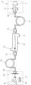
도 1은 본 발명의 제1 실시예에 따른 유동매체 모니터링장치를 도시한 구성도이다.
도 2는 본 발명의 제2 실시예에 따른 유동매체 모니터링장치를 도시한 구성도이다.
도 3은 본 발명의 제3 실시예에 따른 유동매체 모니터링장치를 도시한 구성도이다.Figure 1 is a configuration diagram showing a fluid medium monitoring device according to a first embodiment of the present invention.
Figure 2 is a configuration diagram showing a fluid medium monitoring device according to a second embodiment of the present invention.
Figure 3 is a configuration diagram showing a fluid medium monitoring device according to a third embodiment of the present invention.
이하, 첨부된 도면들을 참조하여 본 발명에 따른 유동매체 모니터링장치의 실시예들을 설명한다. 유동매체 모니터링장치를 설명하는 과정에서 도면에 도시된 선들의 두께나 구성요소의 크기 등은 설명의 명료성과 편의상 과장되게 도시되어 있을 수 있다. 또한, 후술되는 용어들은 본 발명에서의 기능을 고려하여 정의된 용어들로서 이는 사용자, 운용자의 의도 또는 관례에 따라 달라질 수 있다. 그러므로 이러한 용어들에 대한 정의는 본 명세서 전반에 걸친 내용을 토대로 내려져야 할 것이다.Hereinafter, embodiments of a moving medium monitoring device according to the present invention will be described with reference to the attached drawings. In the process of explaining a fluid media monitoring device, the thickness of lines or sizes of components shown in the drawings may be exaggerated for clarity and convenience of explanation. In addition, the terms described below are terms defined in consideration of functions in the present invention, and may vary depending on the intention or custom of the user or operator. Therefore, definitions of these terms should be made based on the content throughout this specification.
먼저, 본 발명의 제1 실시예에 따른 유동매체 모니터링장치에 관해 설명하기로 한다.First, the fluid medium monitoring device according to the first embodiment of the present invention will be described.
도 1은 본 발명의 제1 실시예에 따른 유동매체 모니터링장치를 도시한 구성도이다.Figure 1 is a configuration diagram showing a fluid medium monitoring device according to a first embodiment of the present invention.
도 1을 참조하면, 본 발명의 제1 실시예에 따른 유동매체 모니터링장치는 광원부(10), 제1 컬리메이터부(20), 플로우셀부(30) 및 광검출부(40,50)를 포함한다.Referring to Figure 1, the moving medium monitoring device according to the first embodiment of the present invention includes a
광원부(10)는 광을 조사한다. 이때, 광원부(10)는 광이 조사되는 발광램프(11)와, 발광램프(11)에서 조사되는 광을 집광시키는 볼록렌즈부(13)를 포함한다. 발광램프(11)로는 150-450nm 파장 범위의 자외선(UV: Ultraviolet)을 조사하는 자외선램프가 적용될 수 있다.The
제1 컬리메이터부(20)는 광원부(10)에서 조사되는 광을 평행하게 시준(collimating)한다. 제1 컬리메이터부(20)에서 광을 평행하게 시준하므로, 플로우셀부(30)에는 광이 평행하게 입사된다. 물론, 제1 컬리메이터부(20)는 광학 설계에 따라 광원부(10)에서 조사되는 광을 약간 굴절되게 조사하거나 광의 파장이 교차하도록 조사할 수도 있다.The
제1 컬리메이터부(20)는 볼록렌즈부(13)를 통과한 일정한 각도를 갖는 광을 평행하게 플로우셀부(30)의 내부로 조사한다.The
플로우셀부(30)는 유동매체가 유동되고, 유동매체의 진행방향을 따라 광이 진행되면서 유동매체의 파장을 흡수하게 한다. 플로우셀부(30)의 내부에는 유동매체가 유동되도록 플로우챔버(미도시)가 형성된다. 플로우셀부(30)에서 유동매체의 진행방향을 따라 광이 진행되므로, 광이 유동매체를 투과할 때에 기포나 용출물에 의해 산란 및 굴절되는 것을 최소화하여 광 손실을 감소시킬 수 있다. 또한, 광이 유동매체를 투과하면서 유동매체에 함유된 용출물의 파장을 원활하게 흡수할 수 있으므로, 광검출 효율이 향상될 수 있다.The
유동매체는 반도체 웨이퍼나 태양광셀 등을 제조할 때에 반도체 공정에 사용되는 에칭용액일 수 있다. 에칭용액으로는 150-200℃의 인산용액일 수 있다. 플로우셀부(30)는 고온의 에칭용액에 열변형 및 부식되는 것을 방지할 수 있는 석영재질, 파이렉스 글라스 및 테플론 재질로 형성될 수 있다.The fluid medium may be an etching solution used in a semiconductor process when manufacturing semiconductor wafers or solar cells. The etching solution may be a phosphoric acid solution at 150-200°C. The
플로우셀부(30)의 하부에는 유동매체가 유입되도록 유입관부(31)가 연결되고, 플로우셀부(30)의 상측에는 플로우셀부(30)에서 유동되는 유동매체가 배출되도록 배출관부(33)가 형성된다. 이때, 플로우셀부(30)의 길이방향을 따라 광이 진행된다. 유입관부(31)가 플로우셀부(30)의 하부에 연결되고, 배출관부(33)가 플로우셀부(30)의 상측에 연결되므로, 유동매체가 플로우셀부(30)의 하측에서 상측으로 유동된다. 또한, 유동매체에 함유된 기포는 대부분 플로우셀부(30)의 직경을 가로질러 유동된 후 플로우셀부(30)의 상측을 따라 유동되므로, 광이 플로우셀부(30)의 내부를 따라 유동될 때에 기포에 의해 광손실이 발생되는 것을 최소화할 수 있다.An
플로우셀부(30)에는 유동매체에 함유된 물질이 석출되는 것을 억제하도록 150-200℃로 가열된 유동매체가 유동된다. 또한, 플로우셀부(30)에는 가열된 유동매체의 파장이 광에 흡수되도록 고온의 유동매체가 유동될 수 있다.A fluid medium heated to 150-200° C. flows through the
따라서, 유동매체가 실제의 반도체 공정에 사용되는 조건에서 유동매체의 농도를 측정하고, 유동매체의 검출 감도를 증가시키기 위해 유동매체를 복수 번에 걸쳐 화학처리 할 필요가 없다. 또한, 유동매체를 상온으로 냉각하지 않아도 되므로, 유동매체의 온도차에 의해 검출 오차가 발생되는 것을 방지하고, 실제 반도체 공정에서 적용되는 사용 조건에서 유동매체의 상태를 정확하게 예측할 수 있다. 또한, 농도 분석 중 매트릭스를 간단하게 만들어 분석 농도의 정확성을 향상시킬 수 있다.Therefore, there is no need to measure the concentration of the fluid medium under the conditions in which the fluid medium is used in an actual semiconductor process and to chemically treat the fluid medium multiple times to increase the detection sensitivity of the fluid medium. In addition, since there is no need to cool the fluid medium to room temperature, detection errors caused by temperature differences in the fluid medium can be prevented, and the state of the fluid medium can be accurately predicted under usage conditions applied in actual semiconductor processes. Additionally, the accuracy of the analysis concentration can be improved by simplifying the matrix during concentration analysis.
광검출부(40,50)는 플로우셀부(30)를 통해 조사되는 광의 파장을 검출한다. 광검출부(40,50)는 광이 유동매체를 투과하면서 흡수한 파장을 검출하고, 광검출부(40,50)에서 송신되는 데이터를 분석하여 유동매체에 함유된 용출물의 농도를 측정할 수 있다.The
광검출부(40,50)는 플로우셀부(30)를 통과한 광을 집광하는 제2 컬리메이터부(40)와, 제2 컬리메이터부(40)에서 조사되는 광의 파장을 검출하는 광검출유닛부(50)를 포함한다.The
제2 컬리메이터부(40)는 플로우셀부(30)에서 조사되는 평행한 광을 집광한다. 평행한 광이 제2 컬리메이터부(40)를 투과하면서 집광되므로, 광검출유닛부(50)에서 검출 효율이 향상될 수 있다.The
광검출유닛부(50)는 제2 컬리메이터부(40)에서 조사되는 광의 파장을 검출한다. 광검출유닛부(50)는 광이 유동매체를 투과하면서 흡수한 파장을 검출하고, 광검출유닛부(50)에서 송신되는 데이터를 분석하여 유동매체에 함유된 용출물의 농도를 측정할 수 있다.The light
광검출유닛부(50)는 복수의 파장을 동시에 스캔할 수 있는 CCD 모듈일 수 있다. 따라서, 광검출유닛부(50)에서 복수의 파장을 한 번에 스캔하므로, 광검출유닛부(50)의 광검출 시간을 현저히 감소시킬 수 있다.The light
유동매체 모니터링장치는 광검출유닛부(50)를 냉각시키도록 광검출유닛부(50)에 설치되는 노이즈 저감부(51)를 더 포함한다. 노이즈 저감부(51)는 광검출유닛부(50)를 냉각시킴에 의해 광검출유닛부(50)의 노이즈를 감소시키는 냉각소자나 냉각장치일 수 있다. 노이즈 저감부(51)가 광검출유닛부(50)의 과열을 억제시키므로, 검출 신호의 노이즈가 감소될 수 있다.The moving medium monitoring device further includes a
유동매체 모니터링장치는 제2 컬리메이터부(40)에서 조사되는 평행한 광이 통과하면서 회절되게 하는 슬릿부(53)와, 슬릿부(53)와 광검출유닛부(50) 사이에 배치되고, 슬릿부(53)에서 입사되는 광을 분광시키는 파장선택부(55)를 더 포함한다. 파장선택부(55)로는 광을 복수의 파장으로 분광시키는 회절격자가 적용될 수 있다. 회절격자는 복수의 파장을 거의 평행하게 분광시킨다. 슬릿부(53)와 파장선택부(55)가 광을 복수의 파장으로 분광시키므로, 광검출유닛부(50)에는 복수의 파장이 5-10msec 정도의 짧은 시간 동안에 검출된다. 따라서, 광검출유닛부(50)의 스캔시간이 현저히 감소된다.The flowing medium monitoring device is disposed between a
유동매체 모니터링장치는 광원부(10)와 제1 컬리메이터부(20)에 연결되고, 광원부(10)에서 조사되는 광을 제1 컬리메이터부(20)에 조사하도록 광통로를 형성하는 제1 광섬유부(61)를 더 포함한다. 제1 컬리메이터부(20)와 제1 광섬유부(61)는 제1 광섬유 커플러(62)에 의해 연결된다.The flowing medium monitoring device is connected to the
광원부(10)가 플로우셀부(30)의 설치 위치에 관계없이 다양한 위치에 설치될 수 있으므로, 광원부(10)와 플로우셀부(30)의 설치 자유도를 증가시킬 수 있다.Since the
또한, 제1 광섬유부(61)가 광원부(10)와 제1 컬리메이터부(20)에 연결되므로, 광원부(10)가 플로우셀부(30)와 이격되게 설치될 수 있다. 150-200℃ 정도의 고온의 유동매체가 플로우셀부(30)를 통과하므로, 플로우셀부(30)가 고온의 유동매체에 의해 가열된다. 광원부(10)와 광검출유닛부(50)가 제1 광섬유부(61)에 의해 플로우셀부(30)와 이격되게 설치되므로, 광원부(10)가 플로우셀부(30)의 열기에 의해 과열되는 것을 방지할 수 있다. 또한, 광원부(10)를 냉각시키거나 단열시키기 위해 별도의 냉각장치나 단열부재를 설치하지 않아도 된다.Additionally, since the first
유동매체 모니터링장치는 플로우셀부(30)를 통해 조사되는 평행한 광을 광검출유닛부(50)에 조사하도록 광통로를 형성하는 제2 광섬유부(65)를 더 포함한다. 이때, 제2 광섬유부(65)는 플로우셀부(30)를 통해 광이 입사되는 제2 컬리메이터부(40)와, 광검출유닛부(50)에 연결된다. 제2 광섬유부(65)는 제2 광섬유 커플러(66)에 의해 연결된다.The flowing medium monitoring device further includes a second
또한, 제2 광섬유부(65)는 플로우셀부(30)와 광검출유닛부(50)에 연결될 수 있다.Additionally, the second
광검출유닛부(50)가 플로우셀부(30)의 설치 위치에 관계없이 다양한 위치에 설치될 수 있으므로, 광검출유닛부(50)와 플로우셀부(30)의 설치 자유도를 증가시킬 수 있다.Since the light
또한, 제2 광섬유부(65)가 광검출유닛부(50)와 제2 컬리메이터부(40)에 연결되므로, 광검출유닛부(50)가 플로우셀부(30)와 이격되게 설치될 수 있다. 150-200℃ 정도의 고온의 유동매체가 플로우셀부(30)를 통과하므로, 플로우셀부(30)가 고온의 유동매체에 의해 가열된다. 광검출유닛부(50)가 제2 광섬유부(65)에 의해 플로우셀부(30)와 이격되게 설치되므로, 광검출유닛부(50)가 플로우셀부(30)의 열기에 의해 과열되는 것을 방지할 수 있다. 또한, 광검출유닛부(50)를 냉각시키거나 단열시키기 위해 별도의 냉각장치나 단열부재를 설치하지 않아도 된다.In addition, since the second
유동매체 모니터링장치는 제1 광섬유부(61)와 제2 광섬유부(65) 중 하나만 설치되거나 제1 광섬유부(61)와 제2 광섬유부(65)가 모두 설치될 수 있다. 플로우셀부(30)의 양측에 제1 광섬유부(61)와 제2 광섬유부(65)가 설치되는 경우, 플로우셀부(30), 광원부(10) 및 광검출유닛부(50)를 일렬로 배열해야 하지 않아도 되므로, 유동매체 모니터링장치의 설치 자유도를 증가시킬 수 있다.The moving medium monitoring device may be installed in only one of the first
또한, 유동매체 모니터링장치에는 제1 광섬유부(61)와 제2 광섬유부(65)가 설치되지 않을 수 있다. 이 경우, 광원부(10)와 플로우셀부(30)가 제1 컬리메이터부(20)에 의해 직결되고, 광검출유닛부(50)와 플로우셀부(30)가 제2 컬리메이터부(40)에 의해 직결될 수 있다.Additionally, the first
다음으로, 본 발명의 제2 실시예에 따른 유동매체 모니터링장치에 관해 설명하기로 한다. 제2 실시예에서는 광검출부와 검출파장 조절부를 제외하고는 제1 실시예와 실질적으로 동일하므로, 제1 실시예와 동일한 구성에 관해서는 동일한 도번을 부여하고 그 설명을 생략하기로 한다.Next, the fluid medium monitoring device according to the second embodiment of the present invention will be described. Since the second embodiment is substantially the same as the first embodiment except for the light detection unit and the detection wavelength control unit, the same configuration as the first embodiment will be given the same figure number and the description will be omitted.
도 2는 본 발명의 제2 실시예에 따른 유동매체 모니터링장치를 도시한 구성도이다.Figure 2 is a configuration diagram showing a fluid medium monitoring device according to a second embodiment of the present invention.
도 2를 참조하면, 본 발명의 제2 실시예에 따른 유동매체 모니터링장치는 파장선택부(55)를 회전시킴에 따라 광검출유닛부(50)에 조사되는 광의 파장을 조절하는 검출파장 조절부(57)를 더 포함한다. 검출파장 조절부(57)로는 파장선택부(55)를 1피치씩 회전시킬 수 있는 스텝 모터부(step motor)를 제시한다. 파장선택부(55)가 1피치 회전될 때마다 특정 단위 파장이 순차적으로 광검출유닛부(50)에 조사된다. 검출파장 조절부(57)의 피치각은 단위 파장의 범위에 따라 적절하게 조절될 수 있다. 검출파장 조절부(57)가 1피치씩 회전되면서 단위 파장을 순차적으로 광검출유닛부(50)에 조사하면, 광검출유닛부(50)는 복수의 단위 파장을 하나씩 검출하여 조합한다. 따라서, 복수의 단위 파장을 조합하여 유동매체의 농도 등의 상태를 모니터링할 수 있다.Referring to FIG. 2, the moving medium monitoring device according to the second embodiment of the present invention includes a detection wavelength control unit that adjusts the wavelength of light irradiated to the light
광검출유닛부(50)로는 파장선택부(55)에서 조사되는 단위 파장을 순차적으로 검출할 수 있는 광전자 증배관(PMT 소자: Photomultiplier tube)이 적용될 수 있다. 광전자 증배관이 적용되는 경우, 단위 파장을 순차적으로 판독하므로, 검출 감도가 현저히 증가될 있다. 또한, 복수의 단위 파장을 조합해야 하므로, 분석 속도가 지연될 수 있다.A photomultiplier tube (PMT device: Photomultiplier tube) capable of sequentially detecting unit wavelengths emitted from the
다음으로, 본 발명의 제3 실시예에 따른 유동매체 모니터링장치에 관해 설명하기로 한다. 제3 실시예에서는 파장선택부를 제외하고는 제1 실시예와 실질적으로 동일하므로, 제1 실시예와 동일한 구성에 관해서는 동일한 도번을 부여하고 그 설명을 생략하기로 한다.Next, the fluid medium monitoring device according to the third embodiment of the present invention will be described. Since the third embodiment is substantially the same as the first embodiment except for the wavelength selection unit, the same configuration as the first embodiment will be given the same figure number and the description will be omitted.
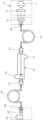
도 3은 본 발명의 제3 실시예에 따른 유동매체 모니터링장치를 도시한 구성도이다.Figure 3 is a configuration diagram showing a fluid medium monitoring device according to a third embodiment of the present invention.
도 3을 참조하면, 본 발명의 제3 실시예에 따른 유동매체 모니터링장치는 광원부(10)와 제1 컬리메이터부(20) 사이에 배치되고, 광원부(10)에서 입사되는 광을 분광시키는 파장선택부(55)를 더 포함한다. 이때, 파장선택부(55)는 제1 광섬유 커플러(62)와 광원부(10)의 볼록렌즈부(13) 사이에 배치된다.Referring to FIG. 3, the moving medium monitoring device according to the third embodiment of the present invention is disposed between the
파장선택부(55)는 광원부(10)에서 조사되는 복수의 단위 파장 중에서 하나의 단위 파장을 선택하여 제1 광섬유부(61)에 전달한다. 하나의 단위 파장은 제1 광섬유부(61)를 통해 제1 컬리메이터부(20), 플로우셀부(30), 제2 컬리메이터부(40) 및 제2 광섬유부(65)를 통해 광검출유닛부(50)에 도달된다. 상기한 하나의 단위 파장은 유동매체에 함유된 복수의 용출물 중 1종의 용출물의 파장을 흡수하는 파장으로 정의된다. 플로우셀부(30)에 하나의 단위 파장이 조사되어 유동매체에서 1종의 용출물의 파장을 흡수하므로, 복수의 파장이 복수 종류의 용출물에서 파장을 흡수할 때에 파장 사이에 스펙트럼의 방해가 발생되는 백그라운드 현상을 방지할 수 있다. 따라서, 단위 파장이 유동매체에 함유된 특정의 용출물에서만 파장을 흡수하므로, 유동매체의 농도 등을 보다 정확하게 검출할 수 있다.The
광검출유닛부(50)와 제2 광섬유 커플러(66) 사이에는 제2 볼록렌즈가 배치된다. 제2 볼록렌즈는 제2 광섬유 커플러(66)에서 조사되는 광을 광검출유닛부(50)에 집광한다. 검출소자로는 감도가 향상되는 광전자 증배관(PMT: Photomultiplier tube) 또는 아발란체 포토다이오드(APD: Avalanche Photo Diode)가 적용될 수 있다.A second convex lens is disposed between the light
본 발명은 도면에 도시된 실시예를 참고로 하여 설명되었으나, 이는 예시적인 것에 불과하며, 당해 기술이 속하는 분야에서 통상의 지식을 가진 자라면 이로부터 다양한 변형 및 균등한 타 실시예가 가능하다는 점을 이해할 것이다.The present invention has been described with reference to the embodiments shown in the drawings, but these are merely exemplary, and those skilled in the art will recognize that various modifications and other equivalent embodiments are possible therefrom. You will understand.
따라서, 본 발명의 진정한 기술적 보호범위는 청구범위에 의해서 정하여져야 할 것이다.Therefore, the true technical protection scope of the present invention should be determined by the claims.
Claims (11)
Translated fromKorean상기 광원부에서 조사되는 자외선을 시준하는 제1 컬리메이터부;
에칭용액인 유동매체가 유동되고, 유동매체의 진행방향을 따라 자외선이 진행되면서 유동매체의 파장을 흡수하게 하는 플로우셀부; 및
상기 플로우셀부를 통과한 자외선의 파장을 검출하는 광검출부를 포함하고,
상기 광검출부는,
상기 플로우셀부를 통과한 자외선을 집광하는 제2 컬리메이터부; 및
상기 제2 컬리메이터부를 통과한 자외선의 파장을 검출하는 광검출유닛부를 포함하고,
냉각소자를 구비하고, 상기 광검출유닛부를 냉각시키도록 광검출유닛부에 설치되는 노이즈 저감부를 더 포함하고,
상기 광원부와 상기 제1 컬리메이터부에 연결되고, 상기 광원부에서 조사되는 자외선을 상기 제1 컬리메이터부에 조사하도록 광통로를 형성하는 제1 광섬유부; 및
상기 플로우셀부를 통해 조사되는 자외선을 상기 광검출유닛부에 조사하도록 광통로를 형성하는 제2 광섬유부를 더 포함하고,
상기 광원부는,
자외선이 조사되는 발광램프; 및
상기 발광램프에서 조사되는 자외선을 집광시키는 볼록렌즈부를 포함하는 것을 특징으로 하는 유동매체 모니터링장치.A light source unit that irradiates ultraviolet rays;
a first collimator unit collimating ultraviolet rays emitted from the light source unit;
A flow cell unit that causes the fluid medium, which is an etching solution, to flow and absorb the wavelength of the fluid medium as ultraviolet rays advance along the direction of flow of the fluid medium; and
It includes a light detection unit that detects the wavelength of ultraviolet rays that passed through the flow cell unit,
The light detection unit,
a second collimator unit that collects ultraviolet rays that have passed through the flow cell unit; and
It includes a light detection unit unit that detects the wavelength of ultraviolet rays that passed through the second collimator unit,
It has a cooling element, and further includes a noise reduction unit installed in the light detection unit to cool the light detection unit,
a first optical fiber unit connected to the light source unit and the first collimator unit and forming an optical path to irradiate ultraviolet rays emitted from the light source unit to the first collimator unit; and
It further includes a second optical fiber unit forming an optical path to irradiate ultraviolet rays irradiated through the flow cell unit to the optical detection unit unit,
The light source unit,
Luminous lamp irradiated with ultraviolet rays; and
A moving medium monitoring device comprising a convex lens unit that focuses ultraviolet rays irradiated from the luminescent lamp.
상기 제1 컬리메이터부는 상기 광원부로부터 일정한 각도를 가지고 입사되는 자외선의 각도를 평행하게 만드는 것을 특징으로 하는 유동매체 모니터링장치.According to claim 1,
The first collimator unit is a moving medium monitoring device characterized in that the angle of ultraviolet rays incident at a certain angle from the light source unit is parallelized.
상기 제2 컬리메이터부는 상기 플로우셀부를 통과한 평행한 자외선을 상기 광검출유닛부에 집광하는 것을 특징으로 하는 유동매체 모니터링장치.According to claim 1,
The second collimator unit focuses parallel ultraviolet rays passing through the flow cell unit to the light detection unit unit.
상기 제2 컬리메이터부에서 조사되는 자외선이 통과하면서 회절되게 하는 슬릿부; 및
상기 슬릿부와 상기 광검출유닛부 사이에 배치되고, 상기 슬릿부에서 입사되는 자외선을 상기 광검출유닛부에 분광하는 파장선택부를 더 포함하는 것을 특징으로 하는 유동매체 모니터링장치.According to claim 1,
a slit portion that causes ultraviolet rays emitted from the second collimator portion to pass through and be diffracted; and
A moving medium monitoring device further comprising a wavelength selection unit disposed between the slit unit and the light detection unit unit and splitting ultraviolet rays incident from the slit unit into the light detection unit unit.
상기 파장선택부를 회전시킴에 따라 상기 광검출부에 조사되는 자외선의 파장을 조절하는 검출파장 조절부를 더 포함하는 것을 특징으로 하는 유동매체 모니터링장치.According to clause 7,
A moving medium monitoring device further comprising a detection wavelength control unit that adjusts the wavelength of ultraviolet rays irradiated to the photodetector by rotating the wavelength selection unit.
상기 광원부와 상기 제1 컬리메이터부 사이에 배치되고, 상기 광원부에서 입사되는 자외선을 분광시키는 파장선택부를 더 포함하는 것을 특징으로 하는 유동매체 모니터링장치.According to claim 1,
A moving medium monitoring device disposed between the light source unit and the first collimator unit and further comprising a wavelength selection unit that specifies ultraviolet rays incident from the light source unit.
Applications Claiming Priority (4)
| Application Number | Priority Date | Filing Date | Title |
|---|---|---|---|
| KR20180113038 | 2018-09-20 | ||
| KR1020190055827AKR20200034563A (en) | 2018-09-20 | 2019-05-13 | Monitoring apparatus of flow media |
| KR1020190055827 | 2019-05-13 | ||
| PCT/KR2020/003822WO2020230995A1 (en) | 2018-09-20 | 2020-03-20 | Fluid medium monitoring apparatus |
Publications (2)
| Publication Number | Publication Date |
|---|---|
| KR20210074392A KR20210074392A (en) | 2021-06-21 |
| KR102580490B1true KR102580490B1 (en) | 2023-09-21 |
Family
ID=70002293
Family Applications (4)
| Application Number | Title | Priority Date | Filing Date |
|---|---|---|---|
| KR1020190055828APendingKR20200034564A (en) | 2018-09-20 | 2019-05-13 | Flow cell apparatus |
| KR1020190055827APendingKR20200034563A (en) | 2018-09-20 | 2019-05-13 | Monitoring apparatus of flow media |
| KR1020217016065AActiveKR102580490B1 (en) | 2018-09-20 | 2020-03-20 | Fluid media monitoring device |
| KR1020217016064AActiveKR102531525B1 (en) | 2018-09-20 | 2020-03-20 | flow cell device |
Family Applications Before (2)
| Application Number | Title | Priority Date | Filing Date |
|---|---|---|---|
| KR1020190055828APendingKR20200034564A (en) | 2018-09-20 | 2019-05-13 | Flow cell apparatus |
| KR1020190055827APendingKR20200034563A (en) | 2018-09-20 | 2019-05-13 | Monitoring apparatus of flow media |
Family Applications After (1)
| Application Number | Title | Priority Date | Filing Date |
|---|---|---|---|
| KR1020217016064AActiveKR102531525B1 (en) | 2018-09-20 | 2020-03-20 | flow cell device |
Country Status (5)
| Country | Link |
|---|---|
| US (2) | US11674875B2 (en) |
| KR (4) | KR20200034564A (en) |
| CN (2) | CN112654852B (en) |
| TW (2) | TWI784250B (en) |
| WO (2) | WO2020230996A1 (en) |
Families Citing this family (2)
| Publication number | Priority date | Publication date | Assignee | Title |
|---|---|---|---|---|
| CN119164882A (en)* | 2024-09-24 | 2024-12-20 | 无锡迅杰光远科技有限公司 | A corrosion-resistant liquid detection flow cell |
| KR102787937B1 (en)* | 2024-09-26 | 2025-03-31 | (주)휴마스 | Photometric water quality measurement device using a variable slit and a multi-stage measuring cell with variable optical path length |
Citations (2)
| Publication number | Priority date | Publication date | Assignee | Title |
|---|---|---|---|---|
| WO2007062800A1 (en)* | 2005-11-29 | 2007-06-07 | Ge Healthcare Bio-Sciences Ab | Methods and apparatus for measuring the concentration of a substance in a solution |
| WO2016171042A1 (en)* | 2015-04-21 | 2016-10-27 | 国立大学法人香川大学 | Spectrometry device |
Family Cites Families (56)
| Publication number | Priority date | Publication date | Assignee | Title |
|---|---|---|---|---|
| CH452233A (en)* | 1964-10-08 | 1968-05-31 | Ceskoslovenska Akademie Ved | Flow photometer arrangement |
| DE1598269A1 (en) | 1965-05-27 | 1971-12-23 | Ceskoslovenska Akademie Ved | Cell for flow photometer |
| US3514210A (en)* | 1968-01-15 | 1970-05-26 | Jiri Hrdina | Device for programmed drawing off of gas bubbles from a measuring cell separator and the liquid from the extinction cell space |
| US4368047A (en)* | 1981-04-27 | 1983-01-11 | University Of Utah Research Foundation | Process for conducting fluorescence immunoassays without added labels and employing attenuated internal reflection |
| US4663961A (en)* | 1985-09-17 | 1987-05-12 | Westinghouse Electric Corp. | System for remote chemical analysis |
| EP0327588B1 (en)* | 1986-11-26 | 1993-05-19 | RUSHBROOKE, John | High sensitivity optical imaging apparatus |
| JPH02212742A (en)* | 1989-02-13 | 1990-08-23 | Kowa Co | Liquid particulate measuring device |
| US5242586A (en)* | 1990-12-17 | 1993-09-07 | Biotage Inc. | Column protection system for liquid chromatography system |
| JP2552940Y2 (en)* | 1992-07-18 | 1997-11-05 | 株式会社堀場製作所 | Particle measurement device |
| KR100196198B1 (en)* | 1995-09-30 | 1999-06-15 | 가시마 쥰이치로 | Coriolis flowmeter |
| JPH10300671A (en)* | 1997-04-22 | 1998-11-13 | Yokogawa Electric Corp | Particle measurement device |
| US6082205A (en)* | 1998-02-06 | 2000-07-04 | Ohio State University | System and device for determining particle characteristics |
| CN1339610A (en)* | 2001-10-09 | 2002-03-13 | 张添 | Time-resolved fluorescnet detection method and detector for gene chip |
| US6854522B2 (en) | 2002-09-23 | 2005-02-15 | Halliburton Energy Services, Inc. | Annular isolators for expandable tubulars in wellbores |
| WO2004040717A2 (en)* | 2002-10-28 | 2004-05-13 | University Of Washington | Wavelength tunable surface plasmon resonance sensor |
| US20060182664A1 (en)* | 2005-02-14 | 2006-08-17 | Peck Bill J | Flow cell devices, systems and methods of using the same |
| US7547904B2 (en)* | 2005-12-22 | 2009-06-16 | Palo Alto Research Center Incorporated | Sensing photon energies emanating from channels or moving objects |
| CN100419406C (en) | 2006-03-31 | 2008-09-17 | 洪陵成 | Flow-thru tank of flow photometric analyzing |
| JP4964647B2 (en)* | 2007-03-30 | 2012-07-04 | ジーエルサイエンス株式会社 | Fluorescence detection device |
| JP2009002806A (en)* | 2007-06-21 | 2009-01-08 | Hitachi Ltd | Chemiluminescence measuring device |
| US20090139311A1 (en)* | 2007-10-05 | 2009-06-04 | Applied Biosystems Inc. | Biological Analysis Systems, Devices, and Methods |
| JP2009162592A (en)* | 2007-12-28 | 2009-07-23 | Nippon Applied Technology Inc | Micro luminescence analyzer |
| JP5190945B2 (en)* | 2008-07-14 | 2013-04-24 | 富士フイルム株式会社 | Detection method, detection apparatus, detection sample cell, and detection kit |
| JP5066110B2 (en)* | 2009-01-30 | 2012-11-07 | 株式会社日立ハイテクノロジーズ | Fluorescence analyzer and fluorescence analysis method |
| JP2010217031A (en)* | 2009-03-17 | 2010-09-30 | Shimadzu Corp | Optical gas analysis system and gas flow cell |
| CN101634748A (en)* | 2009-08-27 | 2010-01-27 | 上海交通大学 | Weak-luminescence and fluorescence optical imaging device and imaging method thereof |
| DE102009059684A1 (en) | 2009-12-19 | 2011-06-22 | J. Eberspächer GmbH & Co. KG, 73730 | Exhaust gas treatment device |
| KR101213059B1 (en)* | 2011-02-23 | 2012-12-18 | 광운대학교 산학협력단 | System of measuring solar cell and controlling method therefor |
| US8817259B2 (en)* | 2011-03-25 | 2014-08-26 | Parker-Hannifin Corporation | Optical sensors for monitoring biopharmaceutical solutions in single-use containers |
| JP5906407B2 (en)* | 2011-04-11 | 2016-04-20 | パナソニックIpマネジメント株式会社 | Gas component detector |
| JP5516486B2 (en)* | 2011-04-14 | 2014-06-11 | 株式会社島津製作所 | Spectrometer and program |
| KR101958387B1 (en)* | 2011-07-28 | 2019-03-20 | 주식회사 동진쎄미켐 | Method of controlling copper-film etching process and method of regenerating copper-film etchant composition using near infrared spectrometer |
| CN202994641U (en)* | 2012-11-13 | 2013-06-12 | 北京瑞升特科技有限公司 | Air bubble releasing device for continuous flow analysis |
| CN104034648A (en)* | 2013-03-05 | 2014-09-10 | 天津炜辐医疗科技有限公司 | Hydrodynamic focusing apparatus used for diffraction imaging flow cytometer |
| JP6121319B2 (en)* | 2013-03-29 | 2017-04-26 | シスメックス株式会社 | Particle measuring apparatus, irradiation optical system, and irradiation position adjusting method |
| CN104103546A (en)* | 2013-04-02 | 2014-10-15 | 盛美半导体设备(上海)有限公司 | Chemical liquid supply and retrieving device |
| CN104865393B (en) | 2014-02-26 | 2017-04-05 | 王军 | A kind of on-line continuous liquid detecting pond for deaerating |
| CN104280355B (en)* | 2014-10-24 | 2017-07-14 | 中国科学院上海光学精密机械研究所 | The detection means and detection method of ammonia and concentration of SO 2 gas |
| CN107810404B (en)* | 2015-03-24 | 2020-11-10 | 伊鲁米那股份有限公司 | Methods, carrier assemblies and systems for imaging samples for biological or chemical analysis |
| WO2016170681A1 (en) | 2015-04-24 | 2016-10-27 | 株式会社島津製作所 | Optical measurement device |
| US10976240B2 (en)* | 2015-08-18 | 2021-04-13 | Tokushima University | Concentration measurement device |
| JP6103008B2 (en)* | 2015-09-09 | 2017-03-29 | ソニー株式会社 | Nonlinear Raman spectroscopic device, microspectroscopic device, and microspectroscopic imaging device |
| CN205235481U (en) | 2015-12-24 | 2016-05-18 | 福建中烟工业有限责任公司 | Color development pond bubble desorption device and continuous flow analytical equipment |
| RU172097U1 (en)* | 2016-04-27 | 2017-06-28 | Общество с ограниченной ответственностью "Производственно-технологический центр "УралАлмазИнвест" | PHOTOMETRIC DEVICE FOR RECOGNITION OF MULTICOMPONENT IMPURITIES OF OIL PRODUCTS IN WATER |
| CN107339522A (en) | 2016-05-03 | 2017-11-10 | 扬中市宏彬冷暖设备有限公司 | A kind of freeze proof elastic pipeline |
| KR102025667B1 (en)* | 2016-06-17 | 2019-09-30 | 주식회사 제우스 | Apparatus for soldering |
| KR101785859B1 (en) | 2016-08-04 | 2017-10-16 | 중앙대학교 산학협력단 | Fluorescent silicon nanoparticle for detecting copper ion, method for preparing the same, and ion detecting sensor using the same |
| KR101970691B1 (en)* | 2016-09-06 | 2019-04-19 | 피엠씨씨 주식회사 | Cell counting and cell size measuring system with a fluid focusing channel |
| JP6688514B2 (en)* | 2016-12-27 | 2020-04-28 | 国立研究開発法人産業技術総合研究所 | Flow cell for optical measurement |
| CN206906244U (en) | 2017-04-25 | 2018-01-19 | 南京舜唯科技工程有限公司 | Coal pulverizer gas analyzer based near infrared spectrum |
| US10591408B2 (en)* | 2017-06-20 | 2020-03-17 | Ci Systems (Israel) Ltd. | Flow cell and optical system for analyzing fluid |
| JP7081146B2 (en)* | 2017-12-27 | 2022-06-07 | 富士電機株式会社 | Gas analyzer |
| US10677767B2 (en)* | 2018-06-12 | 2020-06-09 | Vuv Analytics, Inc. | Vacuum ultraviolet absorption spectroscopy system and method |
| CN208651968U (en) | 2018-07-23 | 2019-03-26 | 临沂红阳管业有限公司 | Prefabricated direct buried steam insulation pipe for urban heating |
| CN113358604B (en)* | 2021-06-02 | 2022-11-01 | 天津大学 | An oblique incident type spectral reflection differential measurement device and method |
| CN113659220A (en)* | 2021-08-05 | 2021-11-16 | 中国民航大学 | Lithium battery thermal runaway early warning system and method based on cavity ring-down spectroscopy technology |
- 2019
- 2019-05-13KRKR1020190055828Apatent/KR20200034564A/enactivePending
- 2019-05-13KRKR1020190055827Apatent/KR20200034563A/enactivePending
- 2020
- 2020-03-20TWTW109109454Apatent/TWI784250B/enactive
- 2020-03-20WOPCT/KR2020/003823patent/WO2020230996A1/ennot_activeCeased
- 2020-03-20USUS17/269,162patent/US11674875B2/enactiveActive
- 2020-03-20USUS17/268,158patent/US12013327B2/enactiveActive
- 2020-03-20KRKR1020217016065Apatent/KR102580490B1/enactiveActive
- 2020-03-20KRKR1020217016064Apatent/KR102531525B1/enactiveActive
- 2020-03-20TWTW109109512Apatent/TWI741537B/enactive
- 2020-03-20CNCN202080004011.0Apatent/CN112654852B/enactiveActive
- 2020-03-20CNCN202080004144.8Apatent/CN112654853B/enactiveActive
- 2020-03-20WOPCT/KR2020/003822patent/WO2020230995A1/ennot_activeCeased
Patent Citations (2)
| Publication number | Priority date | Publication date | Assignee | Title |
|---|---|---|---|---|
| WO2007062800A1 (en)* | 2005-11-29 | 2007-06-07 | Ge Healthcare Bio-Sciences Ab | Methods and apparatus for measuring the concentration of a substance in a solution |
| WO2016171042A1 (en)* | 2015-04-21 | 2016-10-27 | 国立大学法人香川大学 | Spectrometry device |
Also Published As
| Publication number | Publication date |
|---|---|
| KR102531525B1 (en) | 2023-05-15 |
| TWI741537B (en) | 2021-10-01 |
| CN112654853B (en) | 2024-12-24 |
| KR102531525B9 (en) | 2024-12-16 |
| WO2020230996A1 (en) | 2020-11-19 |
| TW202107062A (en) | 2021-02-16 |
| TWI784250B (en) | 2022-11-21 |
| TW202109005A (en) | 2021-03-01 |
| US20220349814A1 (en) | 2022-11-03 |
| WO2020230995A1 (en) | 2020-11-19 |
| CN112654853A (en) | 2021-04-13 |
| KR20200034564A (en) | 2020-03-31 |
| US11674875B2 (en) | 2023-06-13 |
| KR20210074392A (en) | 2021-06-21 |
| US20220057314A1 (en) | 2022-02-24 |
| US12013327B2 (en) | 2024-06-18 |
| CN112654852A (en) | 2021-04-13 |
| KR20200034563A (en) | 2020-03-31 |
| CN112654852B (en) | 2025-03-21 |
| KR20210093917A (en) | 2021-07-28 |
Similar Documents
| Publication | Publication Date | Title |
|---|---|---|
| KR101393143B1 (en) | Substrate processing apparatus | |
| KR102580490B1 (en) | Fluid media monitoring device | |
| JP6286183B2 (en) | Analysis equipment | |
| US10175171B2 (en) | Compact multi-UV-LED probe system and methods of use thereof | |
| JP6500474B2 (en) | Optical analyzer | |
| WO2013192510A1 (en) | Reduction of radiation thermometry bias errors in a cvd reactor | |
| CN207095731U (en) | Transmit thermometric detector | |
| KR102747444B1 (en) | Ndir sensor having multiple channel and toc measuring system including the same | |
| JP2010043983A (en) | Optical measuring device | |
| CN110049818B (en) | Methods and apparatus for optical excitation of multiple analytes in an array of reaction vessels and for collecting fluorescence from the analytes | |
| KR102747450B1 (en) | Ndir sensor having optical waveguide and toc measuring system including the same | |
| US11703391B2 (en) | Continuous spectra transmission pyrometry | |
| KR102555556B1 (en) | Absorption spectrometer | |
| TW202407300A (en) | Optical sensor for remote temperature measurements | |
| US20240242987A1 (en) | Wafer temperature measurement for wet etching bath applications | |
| JP2004271523A (en) | Flow measurement method and measuring apparatus used for it | |
| JP2016217731A (en) | Gas analyzer |
Legal Events
| Date | Code | Title | Description |
|---|---|---|---|
| PA0105 | International application | St.27 status event code:A-0-1-A10-A15-nap-PA0105 | |
| PA0201 | Request for examination | St.27 status event code:A-1-2-D10-D11-exm-PA0201 | |
| PG1501 | Laying open of application | St.27 status event code:A-1-1-Q10-Q12-nap-PG1501 | |
| PN2301 | Change of applicant | St.27 status event code:A-3-3-R10-R13-asn-PN2301 St.27 status event code:A-3-3-R10-R11-asn-PN2301 | |
| E902 | Notification of reason for refusal | ||
| PE0902 | Notice of grounds for rejection | St.27 status event code:A-1-2-D10-D21-exm-PE0902 | |
| AMND | Amendment | ||
| E13-X000 | Pre-grant limitation requested | St.27 status event code:A-2-3-E10-E13-lim-X000 | |
| P11-X000 | Amendment of application requested | St.27 status event code:A-2-2-P10-P11-nap-X000 | |
| P13-X000 | Application amended | St.27 status event code:A-2-2-P10-P13-nap-X000 | |
| E601 | Decision to refuse application | ||
| PE0601 | Decision on rejection of patent | St.27 status event code:N-2-6-B10-B15-exm-PE0601 | |
| X091 | Application refused [patent] | ||
| AMND | Amendment | ||
| E13-X000 | Pre-grant limitation requested | St.27 status event code:A-2-3-E10-E13-lim-X000 | |
| P11-X000 | Amendment of application requested | St.27 status event code:A-2-2-P10-P11-nap-X000 | |
| P13-X000 | Application amended | St.27 status event code:A-2-2-P10-P13-nap-X000 | |
| PX0901 | Re-examination | St.27 status event code:A-2-3-E10-E12-rex-PX0901 | |
| PX0701 | Decision of registration after re-examination | St.27 status event code:A-3-4-F10-F13-rex-PX0701 | |
| X701 | Decision to grant (after re-examination) | ||
| PR0701 | Registration of establishment | St.27 status event code:A-2-4-F10-F11-exm-PR0701 | |
| PR1002 | Payment of registration fee | St.27 status event code:A-2-2-U10-U12-oth-PR1002 Fee payment year number:1 | |
| PG1601 | Publication of registration | St.27 status event code:A-4-4-Q10-Q13-nap-PG1601 | |
| P22-X000 | Classification modified | St.27 status event code:A-4-4-P10-P22-nap-X000 |