KR102580267B1 - Apparatus for measuring biological signal - Google Patents
Apparatus for measuring biological signalDownload PDFInfo
- Publication number
- KR102580267B1 KR102580267B1KR1020180006755AKR20180006755AKR102580267B1KR 102580267 B1KR102580267 B1KR 102580267B1KR 1020180006755 AKR1020180006755 AKR 1020180006755AKR 20180006755 AKR20180006755 AKR 20180006755AKR 102580267 B1KR102580267 B1KR 102580267B1
- Authority
- KR
- South Korea
- Prior art keywords
- substrate
- pulse wave
- measuring unit
- subject
- strain gauge
- Prior art date
- Legal status (The legal status is an assumption and is not a legal conclusion. Google has not performed a legal analysis and makes no representation as to the accuracy of the status listed.)
- Active
Links
Images


Classifications
- A—HUMAN NECESSITIES
- A61—MEDICAL OR VETERINARY SCIENCE; HYGIENE
- A61B—DIAGNOSIS; SURGERY; IDENTIFICATION
- A61B5/00—Measuring for diagnostic purposes; Identification of persons
- A61B5/02—Detecting, measuring or recording for evaluating the cardiovascular system, e.g. pulse, heart rate, blood pressure or blood flow
- A61B5/021—Measuring pressure in heart or blood vessels
- A—HUMAN NECESSITIES
- A61—MEDICAL OR VETERINARY SCIENCE; HYGIENE
- A61B—DIAGNOSIS; SURGERY; IDENTIFICATION
- A61B5/00—Measuring for diagnostic purposes; Identification of persons
- A61B5/68—Arrangements of detecting, measuring or recording means, e.g. sensors, in relation to patient
- A61B5/6801—Arrangements of detecting, measuring or recording means, e.g. sensors, in relation to patient specially adapted to be attached to or worn on the body surface
- A61B5/6843—Monitoring or controlling sensor contact pressure
- A—HUMAN NECESSITIES
- A61—MEDICAL OR VETERINARY SCIENCE; HYGIENE
- A61B—DIAGNOSIS; SURGERY; IDENTIFICATION
- A61B5/00—Measuring for diagnostic purposes; Identification of persons
- A61B5/0059—Measuring for diagnostic purposes; Identification of persons using light, e.g. diagnosis by transillumination, diascopy, fluorescence
- A—HUMAN NECESSITIES
- A61—MEDICAL OR VETERINARY SCIENCE; HYGIENE
- A61B—DIAGNOSIS; SURGERY; IDENTIFICATION
- A61B5/00—Measuring for diagnostic purposes; Identification of persons
- A61B5/02—Detecting, measuring or recording for evaluating the cardiovascular system, e.g. pulse, heart rate, blood pressure or blood flow
- A61B5/024—Measuring pulse rate or heart rate
- A61B5/02416—Measuring pulse rate or heart rate using photoplethysmograph signals, e.g. generated by infrared radiation
- A61B5/02427—Details of sensor
- A—HUMAN NECESSITIES
- A61—MEDICAL OR VETERINARY SCIENCE; HYGIENE
- A61B—DIAGNOSIS; SURGERY; IDENTIFICATION
- A61B5/00—Measuring for diagnostic purposes; Identification of persons
- A61B5/72—Signal processing specially adapted for physiological signals or for diagnostic purposes
- A61B5/7225—Details of analogue processing, e.g. isolation amplifier, gain or sensitivity adjustment, filtering, baseline or drift compensation
- A—HUMAN NECESSITIES
- A61—MEDICAL OR VETERINARY SCIENCE; HYGIENE
- A61B—DIAGNOSIS; SURGERY; IDENTIFICATION
- A61B5/00—Measuring for diagnostic purposes; Identification of persons
- A61B5/74—Details of notification to user or communication with user or patient; User input means
- A61B5/742—Details of notification to user or communication with user or patient; User input means using visual displays
- A61B5/7445—Display arrangements, e.g. multiple display units
- A—HUMAN NECESSITIES
- A61—MEDICAL OR VETERINARY SCIENCE; HYGIENE
- A61B—DIAGNOSIS; SURGERY; IDENTIFICATION
- A61B2562/00—Details of sensors; Constructional details of sensor housings or probes; Accessories for sensors
- A61B2562/02—Details of sensors specially adapted for in-vivo measurements
- A61B2562/0261—Strain gauges
- A—HUMAN NECESSITIES
- A61—MEDICAL OR VETERINARY SCIENCE; HYGIENE
- A61B—DIAGNOSIS; SURGERY; IDENTIFICATION
- A61B2562/00—Details of sensors; Constructional details of sensor housings or probes; Accessories for sensors
- A61B2562/16—Details of sensor housings or probes; Details of structural supports for sensors
- A61B2562/166—Details of sensor housings or probes; Details of structural supports for sensors the sensor is mounted on a specially adapted printed circuit board
- A—HUMAN NECESSITIES
- A61—MEDICAL OR VETERINARY SCIENCE; HYGIENE
- A61B—DIAGNOSIS; SURGERY; IDENTIFICATION
- A61B5/00—Measuring for diagnostic purposes; Identification of persons
- A61B5/68—Arrangements of detecting, measuring or recording means, e.g. sensors, in relation to patient
- A61B5/6887—Arrangements of detecting, measuring or recording means, e.g. sensors, in relation to patient mounted on external non-worn devices, e.g. non-medical devices
- A61B5/6898—Portable consumer electronic devices, e.g. music players, telephones, tablet computers
Landscapes
- Health & Medical Sciences (AREA)
- Life Sciences & Earth Sciences (AREA)
- Engineering & Computer Science (AREA)
- General Health & Medical Sciences (AREA)
- Veterinary Medicine (AREA)
- Biophysics (AREA)
- Biomedical Technology (AREA)
- Heart & Thoracic Surgery (AREA)
- Medical Informatics (AREA)
- Molecular Biology (AREA)
- Surgery (AREA)
- Animal Behavior & Ethology (AREA)
- Physics & Mathematics (AREA)
- Public Health (AREA)
- Pathology (AREA)
- Cardiology (AREA)
- Physiology (AREA)
- Signal Processing (AREA)
- Vascular Medicine (AREA)
- Power Engineering (AREA)
- Artificial Intelligence (AREA)
- Computer Vision & Pattern Recognition (AREA)
- Psychiatry (AREA)
- Measuring Pulse, Heart Rate, Blood Pressure Or Blood Flow (AREA)
Abstract
Translated fromKoreanDescription
Translated fromKorean생체 신호를 측정하는 장치와 관련된다.It is related to a device that measures vital signs.
고령화 사회로의 빠른 진입과 이에 따른 의료비 증가 등의 사회적 문제로 인해 헬스케어 기술이 많은 관심을 받고 있다. 이에 따라 병원이나 검사 기관에서 활용할 수 있는 의료 기기뿐만 아니라, 개인이 휴대할 수 있는 소형 의료 기기가 개발되고 있다.Healthcare technology is receiving a lot of attention due to social problems such as the rapid entry into an aging society and the resulting increase in medical costs. Accordingly, not only medical devices that can be used in hospitals or testing institutions, but also small medical devices that can be carried by individuals are being developed.
또한, 이러한 소형 의료 기기는 사용자에게 착용되어, 혈압 등과 같은 심혈관계 건강 상태를 직접 측정할 수 있는 웨어러블 디바이스(wearable device)의 형태로 보급되어, 사용자가 직접 심혈관계 건강 상태를 측정하고 관리하는 것을 가능하게 하고 있다.In addition, these small medical devices are distributed in the form of wearable devices that can be worn by the user and directly measure cardiovascular health conditions such as blood pressure, allowing users to directly measure and manage their cardiovascular health status. It is making it possible.
따라서, 최근에는 혈압 등과 같은 심혈관계 건강 상태를 측정하는 장치의 소형화에 대한 연구가 많이 진행되고 있다.Therefore, recently, much research has been conducted on miniaturization of devices that measure cardiovascular health conditions such as blood pressure.
생체 신호를 측정하는 장치를 제공하는 것을 목적으로 한다.The purpose is to provide a device for measuring biological signals.
일 양상에 따른 생체 신호 측정 장치는, 기판과, 상기 기판에 형성되어 피검체의 맥파를 측정하는 맥파 측정부와, 상기 기판에 형성된 스트레인 게이지를 포함하고, 상기 스트레인 게이지를 이용하여 상기 기판의 스트레인(strain)을 측정하고, 측정된 스트레인을 기반으로 상기 피검체와 상기 맥파 측정부의 접촉 압력을 측정하는 압력 측정부를 포함할 수 있다.A biological signal measuring device according to one aspect includes a substrate, a pulse wave measuring unit formed on the substrate to measure the pulse wave of a subject, and a strain gauge formed on the substrate, and measures the strain of the substrate using the strain gauge. It may include a pressure measuring unit that measures strain and measures contact pressure between the subject and the pulse wave measuring unit based on the measured strain.
상기 기판은, 인쇄 회로 기판(printed circuit board, PCB) 또는 디스플레이 기판일 수 있다.The board may be a printed circuit board (PCB) or a display board.
상기 기판은, 상기 기판의 단부에서 구조체와 연결될 수 있다.The substrate may be connected to the structure at an end of the substrate.
상기 스트레인 게이지는, 상기 맥파 측정부와 수평적으로 소정 거리 이격되어 상기 기판에 형성될 수 있다.The strain gauge may be formed on the substrate to be horizontally spaced a predetermined distance away from the pulse wave measuring unit.
상기 기판은, 상기 기판의 하부의 복수의 포인트에서 구조체와 연결될 수 있다.The substrate may be connected to the structure at a plurality of points below the substrate.
상기 스트레인 게이지는, 상기 복수의 포인트 사이의 기판 영역에 형성될 수 있다.The strain gauge may be formed in a substrate area between the plurality of points.
생체 신호 측정 장치는, 상기 기판의 하부에 형성된 복수의 지지대를 더 포함하고, 상기 복수의 지지대는 상기 생체 신호 측정 장치가 구조체에서 탈착 가능하도록 상기 구조체와의 수평 방향의 마찰을 최소화하도록 설계될 수 있다.The biological signal measuring device may further include a plurality of supports formed on a lower portion of the substrate, and the plurality of supports may be designed to minimize friction in the horizontal direction with the structure so that the biological signal measuring device can be detached from the structure. there is.
상기 스트레인 게이지는, 상기 복수의 지지대 사이의 기판 영역에 형성될 수 있다.The strain gauge may be formed in a substrate area between the plurality of supports.
상기 맥파 측정부는, 상부 표면이 상기 피검체와 직접 접촉하도록 구현될 수 있다.The pulse wave measuring unit may be implemented so that its upper surface directly contacts the subject.
상기 맥파 측정부는, 상기 기판의 상부 표면으로부터 도출되어 형성될 수 있다.The pulse wave measuring unit may be formed by being derived from the upper surface of the substrate.
상기 맥파 측정부는, 상기 피검체에 광을 조사하는 발광부와, 상기 피검체로부터 반사 또는 산란된 광을 수신하여 상기 피검체의 맥파를 측정하는 수광부를 포함할 수 있다.The pulse wave measuring unit may include a light emitting unit that irradiates light to the subject, and a light receiving unit that measures the pulse wave of the subject by receiving light reflected or scattered from the subject.
다른 양상에 따른 생체 신호 측정 장치는, 기판과, 상기 기판에 형성되어 피검체의 맥파를 측정하는 맥파 측정부와, 상기 기판의 하부와 접촉하는 2 개의 볼록부를 포함하는 플레이트와, 상기 플레이트에 형성된 적어도 하나의 스트레인 게이지를 포함하고, 상기 적어도 하나의 스트레인 게이지를 이용하여 상기 기판의 스트레인(strain)을 측정하고, 측정된 스트레인을 기반으로 상기 피검체와 상기 맥파 측정부의 접촉 압력을 측정하는 압력 측정부를 포함할 수 있다.A biological signal measuring device according to another aspect includes a plate including a substrate, a pulse wave measuring unit formed on the substrate to measure the pulse wave of a subject, and two convex portions in contact with a lower portion of the substrate, and formed on the plate. Pressure measurement comprising at least one strain gauge, measuring strain of the substrate using the at least one strain gauge, and measuring contact pressure between the subject and the pulse wave measuring unit based on the measured strain. May include wealth.
상기 기판은, 인쇄 회로 기판(printed circuit board, PCB) 또는 디스플레이 기판일 수 있다.The board may be a printed circuit board (PCB) or a display board.
상기 플레이트는, 플레이트(150)의 휘어짐이 단축(uniaxial) 방향이 되도록 유도하는 2개의 홀(hole)을 더 포함할 수 있다.The plate may further include two holes that guide the
상기 2개의 홀은, 상기 2개의 볼록부 양 끝단 외측에 평행하게 형성될 수 있다.The two holes may be formed parallel to the outside of both ends of the two convex portions.
상기 적어도 하나의 스트레인 게이지는, 상기 2개의 볼록부 사이에 형성될 수 있다.The at least one strain gauge may be formed between the two convex portions.
상기 맥파 측정부는, 상부 표면이 상기 피검체와 직접 접촉하도록 구현될 수 있다.The pulse wave measuring unit may be implemented so that its upper surface directly contacts the subject.
상기 맥파 측정부는, 상기 기판의 상부 표면으로부터 도출되어 형성될 수 있다.The pulse wave measuring unit may be formed by being derived from the upper surface of the substrate.
상기 맥파 측정부는, 상기 피검체에 광을 조사하는 발광부와, 상기 피검체로부터 반사 또는 산란된 광을 수신하여 상기 피검체의 맥파를 측정하는 수광부를 포함할 수 있다.The pulse wave measuring unit may include a light emitting unit that irradiates light to the subject, and a light receiving unit that measures the pulse wave of the subject by receiving light reflected or scattered from the subject.
스트레인 게이지를 이용하여 사용자의 접촉에 의한 압력을 측정함으로써, 장치의 소형화가 가능하다.By measuring the pressure caused by user contact using a strain gauge, it is possible to miniaturize the device.
도 1은 혈압 측정 장치의 일 실시예를 도시한 블록도이다.
도 2는 생체 신호 측정 장치의 구조의 일 실시예를 도시한 도면이다.
도 3은 생체 신호 측정 장치의 구조의 다른 실시예를 도시한 도면이다.
도 4는 생체 신호 측정 장치의 구조의 또 다른 실시예를 도시한 도면이다.
도 5는 생체 신호 측정 장치의 구조의 또 다른 실시예를 도시한 도면이다.
도 6은 생체 신호 측정 장치의 구조의 또 다른 실시예를 도시한 도면이다.
도 7은 생체 신호 측정 장치의 구조의 또 다른 실시예를 도시한 도면이다.
도 8은 생체 신호 측정 장치의 구조의 또 다른 실시예를 도시한 도면이다.
도 9a는 플레이트의 구조의 일 실시예를 도시한 도면이다.
도 9b는 플레이트가 휘어진 경우의 예를 도시한 도면이다.
도 10은 플레이트 구조의 다른 실시예를 도시한 도면이다.
도 11은 플레이트 구조의 또 다른 실시예를 도시한 도면이다.
도 12는 생체 신호 측정 장치의 구조의 또 다른 실시예를 도시한 도면이다.
도 13은 손목형 웨어러블 디바이스의 일 실시예를 도시한 사시도이다.
도 14a 내지 도 14c는 도 13의 A-A'의 단면도의 일 실시예를 도시한 도면이다.
도 15는 모바일 장치의 일 실시예를 도시한 사시도이다.
도 16은 도 15의 B-B'의 단면도의 일 실시예를 도시한 도면이다.
도 17은 모바일 장치의 다른 실시예를 도시한 사시도이다.
도 18은 도 17의 C-C'의 단면도의 일 실시예를 도시한 도면이다.1 is a block diagram showing an embodiment of a blood pressure measuring device.
FIG. 2 is a diagram illustrating an embodiment of the structure of a biosignal measuring device.
Figure 3 is a diagram showing another embodiment of the structure of a biosignal measuring device.
Figure 4 is a diagram showing another embodiment of the structure of a biosignal measuring device.
Figure 5 is a diagram showing another embodiment of the structure of a biological signal measuring device.
Figure 6 is a diagram showing another embodiment of the structure of a biosignal measuring device.
Figure 7 is a diagram showing another embodiment of the structure of a biosignal measuring device.
Figure 8 is a diagram showing another embodiment of the structure of a biosignal measuring device.
Figure 9a is a diagram showing an example of the structure of a plate.
Figure 9b is a diagram showing an example when the plate is bent.
Figure 10 is a diagram showing another embodiment of the plate structure.
Figure 11 is a diagram showing another embodiment of the plate structure.
Figure 12 is a diagram showing another embodiment of the structure of a biosignal measuring device.
Figure 13 is a perspective view showing an embodiment of a wrist-type wearable device.
FIGS. 14A to 14C are diagrams illustrating an example of a cross-sectional view taken along line A-A' of FIG. 13.
Figure 15 is a perspective view showing an embodiment of a mobile device.
FIG. 16 is a diagram illustrating an example of a cross-sectional view taken along line B-B' of FIG. 15.
Figure 17 is a perspective view showing another embodiment of a mobile device.
FIG. 18 is a diagram illustrating an embodiment of the cross-sectional view taken along line C-C' of FIG. 17.
이하, 첨부된 도면을 참조하여 본 발명의 일 실시예를 상세하게 설명한다. 각 도면의 구성요소들에 참조부호를 부가함에 있어서, 동일한 구성요소들에 대해서는 비록 다른 도면상에 표시되더라도 가능한 한 동일한 부호를 가지도록 하고 있음에 유의해야 한다. 또한, 본 발명을 설명함에 있어 관련된 공지 기능 또는 구성에 대한 구체적인 설명이 본 발명의 요지를 불필요하게 흐릴 수 있다고 판단되는 경우에는 그 상세한 설명을 생략할 것이다.Hereinafter, an embodiment of the present invention will be described in detail with reference to the attached drawings. When adding reference numerals to components in each drawing, it should be noted that identical components are given the same reference numerals as much as possible even if they are shown in different drawings. Additionally, in describing the present invention, if it is determined that a detailed description of a related known function or configuration may unnecessarily obscure the gist of the present invention, the detailed description will be omitted.
한편, 각 단계들에 있어, 각 단계들은 문맥상 명백하게 특정 순서를 기재하지 않은 이상 명기된 순서와 다르게 일어날 수 있다. 즉, 각 단계들은 명기된 순서와 동일하게 수행될 수 있고 실질적으로 동시에 수행될 수도 있으며 반대의 순서대로 수행될 수도 있다.Meanwhile, in each step, unless a specific order is clearly stated in the context, each step may occur in a different order from the specified order. That is, each step may be performed in the same order as specified, may be performed substantially simultaneously, or may be performed in the opposite order.
후술되는 용어들은 본 발명에서의 기능을 고려하여 정의된 용어들로서 이는 사용자, 운용자의 의도 또는 관례 등에 따라 달라질 수 있다. 그러므로 그 정의는 본 명세서 전반에 걸친 내용을 토대로 내려져야 할 것이다.The terms described below are terms defined in consideration of functions in the present invention, and may vary depending on the intention or custom of the user or operator. Therefore, the definition should be made based on the contents throughout this specification.
제1, 제2 등의 용어는 다양한 구성요소들을 설명하는데 사용될 수 있지만, 구성요소들은 용어들에 의해 한정되어서는 안 된다. 용어들은 하나의 구성요소를 다른 구성요소로부터 구별하는 목적으로만 사용된다. 단수의 표현은 문맥상 명백하게 다르게 뜻하지 않는 한 복수의 표현을 포함하고, '포함하다' 또는 '가지다' 등의 용어는 명세서상에 기재된 특징, 숫자, 단계, 동작, 구성요소, 부품 또는 이들을 조합한 것이 존재함을 지정하려는 것이지, 하나 또는 그 이상의 다른 특징들이나 숫자, 단계, 동작, 구성요소, 부품 또는 이들을 조합한 것들의 존재 또는 부가 가능성을 미리 배제하지 않는 것으로 이해되어야 한다.Terms such as first, second, etc. may be used to describe various components, but the components should not be limited by the terms. Terms are used only to distinguish one component from another. Singular expressions include plural expressions unless the context clearly indicates otherwise, and terms such as 'include' or 'have' refer to the features, numbers, steps, operations, components, parts, or combinations thereof described in the specification. It is intended to specify that something exists, but it should be understood as not precluding the possibility of the existence or addition of one or more other features, numbers, steps, operations, components, parts, or combinations thereof.
또한, 본 명세서에서의 구성부들에 대한 구분은 각 구성부가 담당하는 주 기능별로 구분한 것에 불과하다. 즉, 2개 이상의 구성부가 하나의 구성부로 합쳐지거나 또는 하나의 구성부가 보다 세분화된 기능별로 2개 이상으로 분화되어 구비될 수도 있다. 그리고 구성부 각각은 자신이 담당하는 주기능 이외에도 다른 구성부가 담당하는 기능 중 일부 또는 전부의 기능을 추가적으로 수행할 수도 있으며, 구성부 각각이 담당하는 주기능 중 일부 기능이 다른 구성부에 의해 전담되어 수행될 수도 있다. 각 구성부는 하드웨어 또는 소프트웨어로 구현되거나 하드웨어 및 소프트웨어의 결합으로 구현될 수 있다.In addition, the division of components in this specification is merely a division according to the main function each component is responsible for. That is, two or more components may be combined into one component, or one component may be divided into two or more components for more detailed functions. In addition to the main functions that each component is responsible for, each component may additionally perform some or all of the functions that other components are responsible for, and some of the main functions that each component is responsible for may be performed by other components. It may also be carried out. Each component may be implemented as hardware or software, or as a combination of hardware and software.
도 1은 혈압 측정 장치의 일 실시예를 도시한 블록도이다. 도 1의 혈압 측정 장치(10)는 전자 장치에 탑재될 수 있다. 이때 전자 장치는 휴대폰, 스마트폰, 타블렛, 노트북, PDA(Personal Digital Assistants), PMP(Portable Multimedia Player), 네비게이션, MP3 플레이어, 디지털 카메라, 웨어러블 디바이스 등을 포함할 수 있고, 웨어러블 디바이스는 손목시계형, 손목 밴드형, 반지형, 벨트형, 목걸이형, 발목 밴드형, 허벅지 밴드형, 팔뚝 밴드형 등을 포함할 수 있다. 그러나 전자 장치는 상술한 예에 제한되지 않으며, 웨어러블 디바이스 역시 상술한 예에 제한되지 않는다.1 is a block diagram showing an embodiment of a blood pressure measuring device. The blood
도 1을 참조하면, 혈압 측정 장치(10)는 생체 신호 측정부(11) 및 프로세서(12)를 포함할 수 있다.Referring to FIG. 1, the blood
생체 신호 측정부(11)는 피검체의 맥파와, 피검체와 생체 신호 측정부(11) 사이의 접촉 압력을 측정할 수 있다. 이때, 맥파는 광용적맥파(Photoplethysmogram, PPG)일 수 있다.The biological
생체 신호 측정부(11)는 맥파 측정부(110)와 압력 측정부(120)를 포함할 수 있다.The biological
맥파 측정부(110)는 피검체의 맥파를 측정할 수 있다. 이를 위해 맥파 측정부(110)는 발광부(111) 및 수광부(112)를 포함할 수 있다.The pulse
발광부(111)는 피검체에 광을 조사할 수 있다. 예를 들어, 발광부(111)는 가시광선 또는 적외선을 피검체에 조사할 수 있다. 그러나, 측정 목적 등에 따라서 발광부(111)로부터 조사되는 광의 파장은 달라질 수 있다. 그리고 발광부(111)는 반드시 단일의 발광체로 구성될 필요는 없으며, 다수의 발광체의 집합으로 구성될 수도 있다. 발광부(111)가 다수의 발광체의 집합으로 구성되는 경우, 다수의 발광체는 측정 목적에 적합하도록 서로 다른 파장의 광을 방출할 수도 있고 모두 동일한 파장의 광을 방출할 수도 있다. 일 실시예에 따르면 발광부(111)는 발광 다이오드(light emitting diode, LED) 또는 레이저 다이오드(laser diode) 등을 포함할 수 있으나 이는 일 실시예에 불과할 뿐 이에 한정되는 것은 아니다.The
수광부(112)는 피검체로부터 반사 또는 산란된 광을 수신하여 맥파 신호를 측정할 수 있다. 일 실시예에 따르면, 수광부(112)는 포토 다이오드(photo diode), 포토 트랜지스터(photo transistor) 또는 전자 결합 소자(charge-coupled device, CCD)등을 포함할 수 있다. 수광부(112)는 반드시 하나의 소자로 구성될 필요는 없으며, 다수의 소자들이 모여 어레이 형태로 구성될 수도 있다.The
압력 측정부(120)는 피검체가 맥파 측정부(120)를 누를 때 가해지는 압력에 기인한 기판 또는 플레이트(plate)의 스트레인(strain)을 측정하고, 측정된 스트레인을 기반으로 피검체와 맥파 측정부(120) 사이의 접촉 압력을 측정할 수 있다. 이를 위해 압력 측정부(120)는 기판 또는 플레이트에 형성되는 스트레인 게이지(121)를 포함할 수 있다. 일 실시예에 따르면, 압력 측정부(120)는 압력과 기판 또는 플레이트의 스트레인 정도와의 관계를 정의한 압력-스트레인 모델을 이용할 수 있다.The
프로세서(12)는 맥파 측정부(110)에서 측정된 맥파와 압력 측정부(120)에서 측정된 접촉 압력을 기반으로 피검체의 혈압을 추정할 수 있다. 일 실시예에 따르면, 프로세서(12)는 가압/감압 시의 압력 신호를 측정한 뒤 압력 신호의 변화가 가장 큰 지점을 기준으로 혈압을 추정하는 오실로메트릭 기법을 이용하여 피검체의 혈압을 추정할 수 있다.The
도 2는 생체 신호 측정 장치의 구조의 일 실시예를 도시한 도면이다. 도 2의 생체 신호 측정 장치(200)는 도 1의 생체 신호 측정부(11)의 일 실시예일 수 있다.FIG. 2 is a diagram illustrating an embodiment of the structure of a biosignal measuring device. The biological
도 2를 참조하면, 생체 신호 측정 장치(200)는 맥파 측정부(110), 스트레인 게이지(121), 및 기판(130)을 포함할 수 있다.Referring to FIG. 2 , the biological
맥파 측정부(110)는 피검체(2)의 맥파를 측정할 수 있다. 이를 위해 맥파 측정부(110)는 발광부(111) 및 수광부(112)를 포함할 수 있다. 발광부(111)는 피검체(2)에 광을 조사하고, 수광부(112)는 피검체(2)로부터 반사 또는 산란된 광을 수신하여 맥파 신호를 측정할 수 있다. 맥파 측정부(110)는 상부 표면이 기판(130)의 표면에 돌출되지 않고 피검체와 직접 접촉될 수 있도록 기판(130)에 형성될 수 있다.The pulse
기판(130)에는 맥파 측정부(110) 및 스트레인 게이지(121)가 형성될 수 있다. 기판(130)의 단부는 구조체(1)에 연결될 수 있고 이를 통해 기판(130)은 단단하게 고정될 수 있다. 일 실시예에 따르면, 기판(130)은 인쇄 회로 기판(printed circuit board, PCB) 또는 디스플레이 기판일 수 있다.A pulse
스트레인 게이지(121)는 기판(130)에 형성되어 기판(130)의 스트레인을 측정할 수 있다. 피검체(2)가 맥파 측정부(110)를 누를 때의 압력으로 기판(130)은 변형하게 되고 스트레인은 그 변형의 정도를 나타내므로, 기판(130)의 스트레인은 피검체(2)와 맥파 측정부(110)의 접촉 압력을 추정하는데 이용될 수 있다.The
일 실시예에 따르면, 스트레인 게이지(121)는 맥파 측정부(110)와 수평적으로 소정 거리 이격되어 기판(130)에 형성될 수 있다. 이때, 소정 거리는 피검체(2)에 의해 압력이 가해지는 맥파 측정부(110)의 위치와 기판(130)의 스트레인의 방향성을 고려하여 실험적으로 도출될 수 있다.According to one embodiment, the
구조체(1)는 생체 신호 측정 장치(200)가 탑재되는 전자 장치의 구조물(예컨대, 본체 또는 본체의 하우징)일 수 있다. 이때 전자 장치는 휴대폰, 스마트폰, 타블렛, 노트북, PDA(Personal Digital Assistants), PMP(Portable Multimedia Player), 네비게이션, MP3 플레이어, 디지털 카메라, 웨어러블 디바이스 등을 포함할 수 있고, 웨어러블 디바이스는 손목시계형, 손목 밴드형, 반지형, 벨트형, 목걸이형, 발목 밴드형, 허벅지 밴드형, 팔뚝 밴드형 등을 포함할 수 있다. 그러나 전자 장치는 상술한 예에 제한되지 않으며, 웨어러블 디바이스 역시 상술한 예에 제한되지 않는다.The
피검체(2)는 생체 신호 측정 대상으로서 생체 신호 측정 장치의 맥파 측정부(110)와 접촉할 수 있는 생체 영역일 수 있으며, PPG(photoplethysmography)를 통한 맥파 측정이 용이한 인체 부위일 수 있다. 예를 들어 피검체(20)는 손목 표면의 요골 동맥부와 인접한 인체 부위일 수 있다. 그러나, 이에 제한되지 않으며 피검체(2)는 기타 인체 내의 혈관 밀도가 높은 부위인 손가락, 발가락 또는 귓볼 등 인체의 말초 부위일 수도 있다.The
한편, 도 2는 스트레인 게이지(121)가 기판(130)의 하부에 형성되어 있으나, 이에 한정되지 않는다. 즉, 스트레인 게이지(121)가 기판(130)의 상부에 형성되는 것도 가능하다.Meanwhile, in Figure 2, the
도 3은 생체 신호 측정 장치의 구조의 다른 실시예를 도시한 도면이다. 도 3의 생체 신호 측정 장치(300)는 도 1의 생체 신호 측정부(11)의 다른 실시예일 수 있다.Figure 3 is a diagram showing another embodiment of the structure of a biosignal measuring device. The biological
도 3을 참조하면, 생체 신호 측정 장치(300)는 맥파 측정부(110), 스트레인 게이지(121), 및 기판(130)을 포함할 수 있다.Referring to FIG. 3 , the biological
맥파 측정부(110)는 피검체(2)에 광을 조사하는 발광부(111) 및 피검체(2)로부터 반사 또는 산란된 광을 수신하여 맥파 신호를 측정하는 수광부(112)를 포함할 수 있다. 맥파 측정부(110)는 상부 표면이 기판(130)의 상부 표면보다 높게 돌출되어 맥파 측정부(110)의 상부 표면이 피검체와 직접 접촉할 수 있도록 기판(130)에 형성될 수 있다.The pulse
기판(130)에는 맥파 측정부(110) 및 스트레인 게이지(121)가 형성될 수 있다. 기판(130)의 단부는 구조체(1)에 연결될 수 있고 이를 통해 기판(130)은 단단하게 고정될 수 있다. 일 실시예에 따르면, 기판(130)은 인쇄 회로 기판(printed circuit board, PCB) 또는 디스플레이 기판일 수 있다.A pulse
스트레인 게이지(121)는 기판(130)에 형성되어 기판(130)의 스트레인을 측정할 수 있다. 스트레인 게이지(121)는 맥파 측정부(110)와 수평적으로 소정 거리 이격되어 기판(130)에 형성될 수 있다. 이때, 소정 거리는 피검체(2)에 의해 압력이 가해지는 맥파 측정부(110)의 위치와 기판(130)의 스트레인의 방향성을 고려하여 실험적으로 도출될 수 있다.The
한편, 도 3은 스트레인 게이지(121)가 기판(130)의 하부에 형성되어 있으나, 이에 한정되지 않는다. 즉, 스트레인 게이지(121)가 기판(130)의 상부에 형성되는 것도 가능하다.Meanwhile, in Figure 3, the
도 4는 생체 신호 측정 장치의 구조의 또 다른 실시예를 도시한 도면이다. 도 4의 생체 신호 측정 장치(400)는 도 1의 생체 신호 측정부(11)의 또 다른 실시예일 수 있다.Figure 4 is a diagram showing another embodiment of the structure of a biosignal measuring device. The biological
도 4를 참조하면, 생체 신호 측정 장치(400)는 맥파 측정부(110), 스트레인 게이지(121) 및 기판(130)을 포함할 수 있다.Referring to FIG. 4 , the biological
맥파 측정부(110)는 피검체(2)에 광을 조사하는 발광부(111) 및 피검체(2)로부터 반사 또는 산란된 광을 수신하여 맥파 신호를 측정하는 수광부(112)를 포함할 수 있다. 맥파 측정부(110)는 상부 표면이 기판(130)의 표면에 돌출되지 않고 피검체와 직접 접촉될 수 있도록 기판(130)에 형성될 수 있다.The pulse
기판(130)에는 맥파 측정부(110) 및 스트레인 게이지(121)가 형성될 수 있다. 기판(130)은 하부의 복수의 포인트에서 구조체(1)와 연결될 수 있고 이를 통해 기판(130)은 단단하게 고정될 수 있다. 일 실시예에 따르면, 기판(130)은 인쇄 회로 기판(printed circuit board, PCB) 또는 디스플레이 기판일 수 있다.A pulse
스트레인 게이지(121)는 기판(130)에 형성되어 기판(130)의 스트레인을 측정할 수 있다. 일 실시예에 따르면, 스트레인 게이지(121)는 구조체(1)가 연결된 복수의 포인트 사이의 기판(130) 영역에 형성될 수 있다.The
한편, 도 4는 스트레인 게이지(121)가 기판(130)의 하부에 형성되어 있으나, 이에 한정되지 않는다. 즉, 스트레인 게이지(121)가 기판(130)의 상부에 형성되는 것도 가능하다.Meanwhile, in Figure 4, the
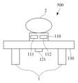
도 5는 생체 신호 측정 장치의 구조의 또 다른 실시예를 도시한 도면이다. 도 5의 생체 신호 측정 장치(500)는 도 1의 생체 신호 측정부(11)의 또 다른 실시예일 수 있다.Figure 5 is a diagram showing another embodiment of the structure of a biological signal measuring device. The biological
도 5를 참조하면, 생체 신호 측정 장치(500)는 맥파 측정부(110), 스트레인 게이지(121) 및 기판(130)을 포함할 수 있다.Referring to FIG. 5 , the biological
맥파 측정부(110)는 피검체(2)에 광을 조사하는 발광부(111) 및 피검체(2)로부터 반사 또는 산란된 광을 수신하여 맥파 신호를 측정하는 수광부(112)를 포함할 수 있다. 맥파 측정부(110)는 상부 표면이 기판(130)의 상부 표면보다 높게 돌출되어 맥파 측정부(110)의 상부 표면이 피검체와 직접 접촉할 수 있도록 기판(130)에 형성될 수 있다.The pulse
기판(130)에는 맥파 측정부(110) 및 스트레인 게이지(121)가 형성될 수 있다. 기판(130)은 하부의 복수의 포인트에서 구조체(1)와 연결될 수 있고 이를 통해 기판(130)은 단단하게 고정될 수 있다. 일 실시예에 따르면, 기판(130)은 인쇄 회로 기판(printed circuit board, PCB) 또는 디스플레이 기판일 수 있다.A pulse
스트레인 게이지(121)는 기판(130)에 형성되어 기판(130)의 스트레인을 측정할 수 있다. 일 실시예에 따르면, 스트레인 게이지(121)는 구조체(1)가 연결된 복수의 포인트 사이의 기판(130) 영역에 형성될 수 있다.The
한편, 도 5는 스트레인 게이지(121)가 기판(130)의 하부에 형성되어 있으나, 이에 한정되지 않는다. 즉, 스트레인 게이지(121)가 기판(130)의 상부에 형성되는 것도 가능하다.Meanwhile, in Figure 5, the
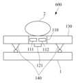
도 6은 생체 신호 측정 장치의 구조의 또 다른 실시예를 도시한 도면이다. 도 6의 생체 신호 측정 장치(600)는 도 1의 생체 신호 측정부(11)의 또 다른 실시예일 수 있다.Figure 6 is a diagram showing another embodiment of the structure of a biosignal measuring device. The biological
도 6을 참조하면, 생체 신호 측정 장치(600)는 맥파 측정부(110), 스트레인 게이지(121), 기판(130), 및 복수의 지지대(140)를 포함할 수 있다.Referring to FIG. 6 , the biological
맥파 측정부(110)는 피검체(2)에 광을 조사하는 발광부(111) 및 피검체(2)로부터 반사 또는 산란된 광을 수신하여 맥파 신호를 측정하는 수광부(112)를 포함할 수 있다. 맥파 측정부(110)는 상부 표면이 기판(130)의 표면에 돌출되지 않고 피검체와 직접 접촉될 수 있도록 기판(130)에 형성될 수 있다.The pulse
기판(130)에는 맥파 측정부(110), 스트레인 게이지(121) 및 복수의 지지대(140)가 형성될 수 있다. 일 실시예에 따르면, 기판은 인쇄 회로 기판(printed circuit board, PCB) 또는 디스플레이 기판일 수 있다.A pulse
스트레인 게이지(121)는 기판(130)에 형성되어 기판(130)의 스트레인을 측정할 수 있다. 일 실시예에 따르면, 스트레인 게이지(121)는 복수의 지지대(140) 사이의 기판(130) 영역에 형성될 수 있다.The
지지대(140)는 기판(130)의 하부에 형성되어, 기판(130)과 구조체(1) 사이에 공간을 형성할 수 있다. 지지대(140)는 생체 신호 측정 장치(600)가 구조체(1)에서 탈착 가능하도록 구조체(1)와의 수평 방향의 마찰을 최소화하도록 설계될 수 있다.The
한편, 도 6는 스트레인 게이지(121)가 기판(130)의 하부에 형성되어 있으나, 이에 한정되지 않는다. 즉, 스트레인 게이지(121)가 기판(130)의 상부에 형성되는 것도 가능하다.Meanwhile, in Figure 6, the
도 7은 생체 신호 측정 장치의 구조의 또 다른 실시예를 도시한 도면이다. 도 7의 생체 신호 측정 장치(700)는 도 1의 생체 신호 측정부(11)의 또 다른 실시예일 수 있다.Figure 7 is a diagram showing another embodiment of the structure of a biosignal measuring device. The
도 7을 참조하면, 생체 신호 측정 장치(700)는 맥파 측정부(110), 스트레인 게이지(121), 기판(130), 및 복수의 지지대(140)를 포함할 수 있다.Referring to FIG. 7 , the biological
맥파 측정부(110)는 피검체(2)에 광을 조사하는 발광부(111) 및 피검체(2)로부터 반사 또는 산란된 광을 수신하여 맥파 신호를 측정하는 수광부(112)를 포함할 수 있다. 맥파 측정부(110)는 상부 표면이 기판(130)의 상부 표면보다 높게 돌출되어 맥파 측정부(110)의 상부 표면이 피검체와 직접 접촉할 수 있도록 형성될 수 있다.The pulse
기판(130)에는 맥파 측정부(110), 스트레인 게이지(121) 및 복수의 지지대(140)가 형성될 수 있다. 일 실시예에 따르면, 기판(130)은 인쇄 회로 기판(printed circuit board, PCB) 또는 디스플레이 기판일 수 있다.A pulse
스트레인 게이지(121)는 기판(130)에 형성되어 기판(130)의 스트레인을 측정할 수 있다. 일 실시예에 따르면, 스트레인 게이지(121)는 복수의 지지대(140) 사이의 기판(130) 영역에 형성될 수 있다.The
지지대(140)는 기판(130)의 하부에 형성되어, 기판(130)과 구조체(1) 사이에 공간을 형성할 수 있다. 지지대(140)는 생체 신호 측정 장치(600)가 구조체(1)에서 탈착 가능하도록 구조체(1)와의 수평 방향의 마찰을 최소화하도록 설계될 수 있다.The
한편, 도 7은 스트레인 게이지(121)가 기판(130)의 하부에 형성되어 있으나, 이에 한정되지 않는다. 즉, 스트레인 게이지(121)가 기판(130)의 상부에 형성되는 것도 가능하다.Meanwhile, in Figure 7, the
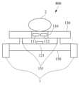
도 8은 생체 신호 측정 장치의 구조의 또 다른 실시예를 도시한 도면이다. 도 8의 생체 신호 측정 장치(800)는 도 1의 생체 신호 측정부(11)의 또 다른 실시예일 수 있다.Figure 8 is a diagram showing another embodiment of the structure of a biosignal measuring device. The
도 8을 참조하면, 생체 신호 측정 장치(800)는 맥파 측정부(110), 스트레인 게이지(121), 기판(130), 및 플레이트(plate)(150)를 포함할 수 있다.Referring to FIG. 8 , the biological
맥파 측정부(110)는 피검체(2)에 광을 조사하는 발광부(111) 및 피검체(2)로부터 반사 또는 산란된 광을 수신하여 맥파 신호를 측정하는 수광부(112)를 포함할 수 있다. 맥파 측정부(110)는 상부 표면이 기판(130)의 표면에 돌출되지 않고 피검체와 직접 접촉될 수 있도록 기판(130)에 형성될 수 있다.The pulse
기판(130)에는 맥파 측정부(110)가 형성될 수 있다. 일 실시예에 따르면, 기판(130)은 인쇄 회로 기판(printed circuit board, PCB) 또는 디스플레이 기판일 수 있다.A pulse
플레이트(150)는 볼록부(151)를 포함할 수 있다. 플레이트(150)는 볼록부(151)를 통하여 기판(130)과 면 접촉하거나 점 접촉할 수 있다. 일 실시예에 따르면, 플레이트(150)는 기판(130)에 작용하는 힘에 기인한 플레이트(150)의 휘어짐이 단축(uniaxial) 방향이 되도록 유도하는 복수의 홀(hole)을 포함할 수 있다.
한편, 플레이트(150)는 단부는 구조체(1)에 연결될 수 있고 이를 통해 플레이트(150)는 단단하게 고정될 수 있다.Meanwhile, the end of the
플레이트(150)에 대한 구체적인 구조는 도 8 내지 도 11을 참조하여 후술하기로 한다.The specific structure of the
스트레인 게이지(121)는 플레이트(150)에 형성되어 플레이트(150)의 스트레인을 측정할 수 있다. 피검체(2)가 맥파 측정부(110)를 누를 때의 압력은 볼록부(151)를 통해 기판(130)으로부터 플레이트(150)로 전달된다. 플레이트(150)로 전달된 힘에 의해 플레이트(150)는 변형하게 되고 스트레인은 그 변형의 정도를 나타내므로, 플레이트(150)의 스트레인은 피검체(2)와 맥파 측정부(110)의 접촉 압력을 추정하는데 이용될 수 있다. 일 실시예에 따르면, 스트레인 게이지(121)는 볼록부(151) 사이의 플레이트(150) 영역에 적어도 하나 이상 형성될 수 있다.The
한편, 도 8은 스트레인 게이지(121)가 플레이트(150)의 상부에 형성되어 있으나, 이에 한정되지 않는다. 즉, 스트레인 게이지(121)가 플레이트(150)의 하부에 형성되는 것도 가능하다.Meanwhile, in Figure 8, the
도 9a는 플레이트의 구조의 일 실시예를 도시한 도면이고, 도 9b는 플레이트가 휘어진 경우의 예시도이다. 도 9a의 플레이트(900)는 도 8의 플레이트(150)의 일 실시예일 수 있다.FIG. 9A is a diagram illustrating an example of the structure of a plate, and FIG. 9B is an example diagram of a bent plate. The
도 9a 및 도 9b를 참조하면, 플레이트(900)는 2개의 볼록부(151)와 2개의 홀(152)을 포함할 수 있다.Referring to FIGS. 9A and 9B, the
2개의 볼록부(151)는 소정 간격으로 플레이트(900)의 상부에 평행하게 형성되며, 2개의 홀(152)은 플레이트(150)의 휘어짐이 단축(uniaxial) 방향이 될 수 있도록 2개의 볼록부(151) 양 끝단 외측에 평행하게 형성될 수 있다. 이때, 2개의 홀(152) 각각의 길이는 2개의 볼록부(151) 사이의 간격보다 길 수 있다.Two
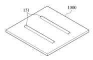
도 10은 플레이트 구조의 다른 실시예를 도시한 도면이다. 도 10의 플레이트(1000)는 도 8의 플레이트(150)의 다른 실시예일 수 있다.Figure 10 is a diagram showing another embodiment of the plate structure. The
도 10을 참조하면, 플레이트(1000)는 2개의 볼록부(151)를 포함할 수 있다. 즉, 플레이트(1000)는 도 9의 플레이트(900)에서 2개의 홀(152)이 생략된 구조를 가질 수 있다.Referring to FIG. 10 , the
이 경우, 2개의 볼록부(151)를 통해 플레이트(150)에 힘이 전달되면, 플레이트(150)는 복수축 방향으로 휘어질 수 있다. 따라서, 도 10의 플레이트(1000)가 도 8의 생체 신호 측정 장치(800)에 적용되는 경우, 2개 이상의 스트레인 게이지(121)가 플레이트(150)의 2개의 볼록부(151) 사이에 형성될 수 있다. 2개 이상의 스트레인 게이지(121)를 사용함으로써 스트레인 게이지 1개를 사용할 때보다 정확하게 스트레인의 방향성을 알 수 있고, 이를 통해 피검체(2)와 맥파 측정부(110)의 접촉 압력을 더욱 정확히 추정하는 것이 가능하다.In this case, when force is transmitted to the
도 11은 플레이트 구조의 또 다른 실시예를 도시한 도면이다. 도 10의 플레이트(1100)는 도 8의 플레이트(150)의 또 다른 실시예일 수 있다.Figure 11 is a diagram showing another embodiment of the plate structure. The
도 11을 참조하면, 플레이트(1100)는 1개의 사각형의 볼록부(151)를 포함할 수 있다.Referring to FIG. 11, the
이 경우, 1개의 사각형의 볼록부(151)를 통해 플레이트(150)에 힘이 전달되면, 플레이트(150)는 복수축 방향으로 휘어질 수 있다 따라서, 도 11의 플레이트(1000)가 도 8의 생체 신호 측정 장치(800)에 적용되는 경우, 2개 이상의 스트레인 게이지(121)가 플레이트(150)의 볼록부(151) 사이에 형성될 수 있다. 2개 이상의 스트레인 게이지(121)를 사용함으로써 스트레인 게이지 1개를 사용할 때보다 정확하게 스트레인의 방향성을 알 수 있고, 이를 통해 피검체(2)와 맥파 측정부(110)의 접촉 압력을 더욱 정확히 추정하는 것이 가능하다.In this case, when force is transmitted to the
한편, 도 11은 플에이트(1100)가 1개의 사각형의 볼록부(151)를 포함하는 것으로 도시되나, 이는 일 실시예일뿐, 볼록부(151)의 모양에 특별한 제한이 없다. 즉, 볼록부(151)는 원, 삼각형 등으로 형성되는 것도 가능하다.Meanwhile, Figure 11 shows that the
도 12는 생체 신호 측정 장치의 구조의 또 다른 실시예를 도시한 도면이다. 도 12의 생체 신호 측정 장치(1200)는 도 1의 생체 신호 측정부(11)의 또 다른 실시예일 수 있다.Figure 12 is a diagram showing another embodiment of the structure of a biosignal measuring device. The
도 12를 참조하면, 생체 신호 측정 장치(800)는 맥파 측정부(110), 스트레인 게이지(121), 기판(130), 및 플레이트(plate)(150)를 포함할 수 있다.Referring to FIG. 12 , the biological
맥파 측정부(110)는 피검체(2)에 광을 조사하는 발광부(111) 및 피검체(2)로부터 반사 또는 산란된 광을 수신하여 맥파 신호를 측정하는 수광부(112)를 포함할 수 있다. 맥파 측정부(110)는 상부 표면이 기판(130)의 상부 표면보다 높게 돌출되어 맥파 측정부(110)의 상부 표면이 피검체와 직접 접촉할 수 있도록 형성될 수 있다.The pulse
기판(130)에는 맥파 측정부(110)가 형성될 수 있다. 일 실시예에 따르면, 기판(130)은 인쇄 회로 기판(printed circuit board, PCB) 또는 디스플레이 기판일 수 있다.A pulse
플레이트(150)는 볼록부(151)를 포함할 수 있다. 플레이트(150)는 볼록부(151)를 통하여 기판(130)과 면 접촉하거나 점 접촉할 수 있다. 일 실시예에 따르면, 플레이트(150)는 기판(130)에 작용하는 힘에 기인한 플레이트(150)의 휘어짐이 단축(uniaxial) 방향이 되도록 유도하는 복수의 홀(hole)을 포함할 수 있다.
한편, 플레이트(150)는 단부는 구조체(1)에 연결될 수 있고 이를 통해 플레이트(150)는 단단하게 고정될 수 있다.Meanwhile, the end of the
스트레인 게이지(121)는 플레이트(150)에 형성되어 플레이트(150)의 스트레인을 측정할 수 있다. 피검체(2)가 맥파 측정부(110)를 누를 때의 압력은 볼록부(151)를 통해 기판(130)으로부터 플레이트(150)로 전달된다. 플레이트(150)로 전달된 힘에 의해 플레이트(150)는 변형하게 되고 스트레인은 그 변형의 정도를 나타내므로, 플레이트(150)의 스트레인은 피검체(2)와 맥파 측정부(110)의 접촉 압력을 추정하는데 이용될 수 있다. 일 실시예에 따르면, 스트레인 게이지(121)는 볼록부(151) 사이의 플레이트(150) 영역에 적어도 하나 이상 형성될 수 있다.The
한편, 도 12는 스트레인 게이지(121)가 플레이트(150)의 상부에 형성되어 있으나, 이에 한정되지 않는다. 즉, 스트레인 게이지(121)가 플레이트(150)의 하부에 형성되는 것도 가능하다.Meanwhile, in Figure 12, the
도 13은 손목형 웨어러블 디바이스의 일 실시예를 도시한 사시도이고, 도 14a 내지 도 14c는 도 13의 A-A'의 단면도의 일 실시예를 도시한 도면이다. 자세하게는, 도 14a는 도 2의 생체 신호 측정 장치(200)가 손목형 웨어러블 디바이스에 탑재된 경우의 단면도이고, 도 14b는 도 6의 생체 신호 측정 장치(600)가 손목형 웨어러블 디바이스에 탑재된 경우의 단면도이고, 도 14c는 도 8의 생체 신호 측정 장치(800)가 손목형 웨어러블 디바이스에 탑재된 경우의 단면도이다.FIG. 13 is a perspective view illustrating an embodiment of a wrist-type wearable device, and FIGS. 14A to 14C are diagrams illustrating an embodiment of the cross-sectional view taken along line A-A' of FIG. 13 . In detail, FIG. 14A is a cross-sectional view of the biological
도 13, 도 14a 내지 도 14c를 참조하면, 손목형 웨어러블 디바이스(1300)는 스트랩(1310) 및 본체(1320)를 포함할 수 있다.Referring to FIGS. 13 and 14A to 14C , the wrist-type
스트랩(1310)은 본체(1320)의 양측에 연결되어 서로 체결될 수 있도록 분리 형성되거나, 스마트 밴드 형태로 일체로 형성될 수 있다. 스트랩(1310)은 본체(1320)가 사용자의 손목에 착용되도록 손목을 감쌀 수 있도록 플렉서블(flexible)한 부재로 형성될 수 있다.The
본체(1320)는 하우징(1324) 내부에 전술한 혈압 측정 장치(10) 및/또는 생체 신호 측정 장치(200, 300, 400, 500, 600, 700, 800, 1200)를 탑재할 수 있다. 예를 들어, 도 14a에 도시된 바와 같이 하우징(1324) 내부에 맥파 측정부(110)와 스트레인 게이지(121)가 형성된 기판(130)을 포함하거나, 도 14b에 도시된 바와 같이 하우징(1324) 내부에 맥파 측정부(110), 스트레인 게이지(121) 및 복수의 지지대(140)가 형성된 기판(130)을 포함하거나, 도 14c에 도시된 바와 같이 맥파 측정부(110)가 형성된 기판(130)과, 볼록부(151) 및 스트레인 게이지(121)가 형성된 플레이트(150)를 포함할 수 있다.The
한편, 도 14a 내지 도 14c의 단면도는 일 실시예에 불과할 뿐, 이에 한정되지 않는다. 즉, 도 14a 내지 도 14c와 유사하게 전술한 생체 신호 측정 장치(200, 300, 400, 500, 600, 700, 800, 1200)의 구조가 반영될 수 있다. 또한, 도 14a 내지 도 14c는 맥파 측정부(110) 및 기판(130)이 하우징(1324)의 표면보다 낮게 형성되어 있으나 이에 한정되는 것은 아니며 맥파 측정부(110) 및 기판(130)이 하우징(1324)의 표면과 동일한 높이로 형성되거나 하우징(1324) 표면에 돌출되도록 형성될 수도 있다.Meanwhile, the cross-sectional view of FIGS. 14A to 14C is only an example and is not limited thereto. That is, similar to FIGS. 14A to 14C, the structure of the
또한, 본체(1320)의 하우징(1324) 내부에는 손목형 웨어러블 디바이스(1300), 혈압 측정 장치(10) 및 생체 신호 측정 장치(200, 300, 400, 500, 600,700, 800, 1200)에 전원을 공급하는 배터리, 및 다양한 소자가 형성된 기판(1323)을 더 포함할 수 있다.In addition, inside the
일 실시예에 따르면, 맥파 측정부(110)는 본체(1320) 하부에 사용자의 손목을 향해 노출되도록 장착될 수 있다. 이를 통해 사용자가 손목형 웨어러블 디바이스(1300)를 착용하면 자연스럽게 맥파 측정부(110)가 사용자의 피부에 접촉할 수 있다. 그러나, 이는 일 실시예에 불과할 뿐, 맥파 측정부(110)가 본체(1320) 상부의 디스플레이 영역 또는 디스플레이 이외의 영역에 장착될 수도 있다.According to one embodiment, the pulse
손목형 웨어러블 디바이스(1300)는 본체(1320)에 장착되는 디스플레이(1321)와 입력부(1322)를 더 포함할 수 있다. 디스플레이(1321)는 손목형 웨어러블 디바이스(1300), 혈압 측정 장치(10) 및 생체 신호 측정 장치(200, 300, 400, 500, 600, 700, 800, 1200)에서 처리된 데이터 및 처리 결과 데이터 등을 표시할 수 있다. 이때 디스플레이(1321)는 터치스크린으로 구현되어 출력 수단뿐만 아니라 입력 수단으로서 동작할 수 있다. 입력부(1322)는 사용자로부터 다양한 조작신호를 입력 받을 수 있다.The wrist-type
도 15는 모바일 장치의 일 실시예를 도시한 사시도이고, 도 16은 도 15의 B-B'의 단면도의 일 실시예를 도시한 도면이다. 자세하게는, 도 16은 도 2의 생체 신호 측정 장치(200)가 모바일 장치에 탑재된 경우의 단면도이다.FIG. 15 is a perspective view illustrating an embodiment of a mobile device, and FIG. 16 is a diagram illustrating an embodiment of the cross-sectional view taken along line B-B' of FIG. 15. In detail, FIG. 16 is a cross-sectional view when the
도 15 및 도 16을 참조하면, 모바일 장치(1500)는 하우징(1520) 내부에 전술한 혈압 측정 장치(10) 및/또는 생체 신호 측정 장치(200, 300, 400, 500, 600, 700, 800, 1200)를 탑재할 수 있다. 예를 들어, 도 16에 도시된 바와 같이 하우징(1520) 내부에 맥파 측정부(110)와 스트레인 게이지(121)가 형성된 기판(130)을 포함할 수 있다. 이때 맥파 측정부(110)는 모바일 장치(1500)의 후면에 노출되어 장착될 수 있다.15 and 16, the
한편, 도 16의 단면도는 일 실시예에 불과할 뿐, 이에 한정되지 않는다. 즉, 도 16과 유사하게 전술한 생체 신호 측정 장치(200, 300, 400, 500, 600, 700, 800, 1200)의 구조가 반영될 수 있다. 또한, 도 16은 맥파 측정부(110) 및 기판(130)이 하우징(1520)의 표면보다 낮게 형성되어 있으나 이에 한정되는 것은 아니며 맥파 측정부(110) 및 기판(130)이 하우징(1520)의 표면과 동일한 높이로 형성되거나 하우징(1520) 표면에 돌출되도록 형성될 수도 있다.Meanwhile, the cross-sectional view of FIG. 16 is only an example and is not limited thereto. That is, similar to FIG. 16 , the structures of the
또한, 하우징(1520) 내부에는 모바일 장치(1500), 혈압 측정 장치(10) 및 생체 신호 측정 장치(200, 300, 400, 500, 600,700, 800, 1200)에 전원을 공급하는 배터리, 및 다양한 소자가 형성된 기판(1540)을 더 포함할 수 있다.Additionally, inside the
모바일 장치(1500)는 디스플레이(1530)를 더 포함할 수 있다. 디스플레이(1530)는 모바일 디바이스(1500), 혈압 측정 장치(10) 및 생체 신호 측정 장치(200, 300, 400, 500, 600, 700, 800, 1200)에서 처리된 데이터 및 처리 결과 데이터 등을 표시할 수 있다. 이때 디스플레이(1530)는 터치스크린으로 구현되어 출력 수단뿐만 아니라 입력 수단으로서 동작할 수 있다.
도 17은 모바일 장치의 다른 실시예를 도시한 사시도이고, 도 18은 도 17의 C-C'의 단면도의 일 실시예를 도시한 도면이다. 자세하게는, 도 18은 도 2의 생체 신호 측정 장치(200)가 모바일 장치에 탑재된 경우의 단면도이다.FIG. 17 is a perspective view illustrating another embodiment of a mobile device, and FIG. 18 is a diagram illustrating an embodiment of the cross-sectional view taken along line C-C' of FIG. 17. In detail, FIG. 18 is a cross-sectional view when the
도 17 및 도 18을 참조하면, 모바일 장치(1800)는 하우징(1720) 내부에 전술한 혈압 측정 장치(10) 및/또는 생체 신호 측정 장치(200, 300, 400, 500, 600, 700, 800, 1200)를 탑재할 수 있다. 예를 들어, 도 16에 도시된 바와 같이 하우징(1720) 내부에 맥파 측정부(110)와 스트레인 게이지(121)가 형성된 기판(130)을 포함할 수 있다. 이때 맥파 측정부(110)는 모바일 장치(1700)의 전면 중 디스플레이(1710)가 없는 영역에 노출되어 장착될 수 있다.17 and 18, the mobile device 1800 includes the above-described blood
한편, 도 18의 단면도는 일 실시예에 불과할 뿐, 이에 한정되지 않는다. 즉, 도 18과 유사하게 전술한 생체 신호 측정 장치(200, 300, 400, 500, 600, 700, 800, 1200)의 구조가 반영될 수 있다. 또한, 도 18은 맥파 측정부(110) 및 기판(130)이 하우징(1720)의 표면보다 낮게 형성되어 있으나 이에 한정되는 것은 아니며 맥파 측정부(110) 및 기판(130)이 하우징(1720)의 표면과 동일한 높이로 형성되거나 하우징(1720) 표면에 돌출되도록 형성될 수도 있다.Meanwhile, the cross-sectional view of FIG. 18 is only an example and is not limited thereto. That is, similar to FIG. 18 , the structures of the
또한, 하우징(1720) 내부에는 모바일 장치(1700), 혈압 측정 장치(10) 및 생체 신호 측정 장치(200, 300, 400, 500, 600,700, 800, 1200)에 전원을 공급하는 배터리, 및 다양한 소자가 형성된 기판(1740)을 더 포함할 수 있다.Additionally, inside the
모바일 장치(1700)는 입력부(1710)와 디스플레이(1730) 더 포함할 수 있다. 입력부(1710)는 사용자로부터 다양한 조작신호를 입력 받을 수 있다. 디스플레이(1730)는 모바일 디바이스(1700), 혈압 측정 장치(10) 및 생체 신호 측정 장치(200, 300, 400, 500, 600, 700, 800, 1200)에서 처리된 데이터 및 처리 결과 데이터 등을 표시할 수 있다. 이때 디스플레이(1730)는 터치스크린으로 구현되어 출력 수단뿐만 아니라 입력 수단으로서 동작할 수 있다.The
본 발명의 일 양상은 컴퓨터로 읽을 수 있는 기록 매체에 컴퓨터가 읽을 수 있는 코드로서 구현될 수 있다. 상기의 프로그램을 구현하는 코드들 및 코드 세그먼트들은 당해 분야의 컴퓨터 프로그래머에 의하여 용이하게 추론될 수 있다. 컴퓨터가 읽을 수 있는 기록 매체는 컴퓨터 시스템에 의하여 읽혀질 수 있는 데이터가 저장되는 모든 종류의 기록 장치를 포함할 수 있다. 컴퓨터가 읽을 수 있는 기록 매체의 예로는 ROM, RAM, CD-ROM, 자기 테이프, 플로피 디스크, 광 디스크 등을 포함할 수 있다. 또한, 컴퓨터가 읽을 수 있는 기록 매체는 네트워크로 연결된 컴퓨터 시스템에 분산되어, 분산 방식으로 컴퓨터가 읽을 수 있는 코드로 작성되고 실행될 수 있다.An aspect of the present invention may be implemented as computer-readable code on a computer-readable recording medium. Codes and code segments implementing the above program can be easily deduced by a computer programmer in the art. Computer-readable recording media may include all types of recording devices that store data that can be read by a computer system. Examples of computer-readable recording media may include ROM, RAM, CD-ROM, magnetic tape, floppy disk, optical disk, etc. Additionally, the computer-readable recording medium may be distributed over a computer system connected to a network, and may be written and executed as computer-readable code in a distributed manner.
이제까지 본 발명에 대하여 그 바람직한 실시 예들을 중심으로 살펴보았다. 본 발명이 속하는 기술 분야에서 통상의 지식을 가진 자는 본 발명이 본 발명의 본질적인 특성에서 벗어나지 않는 범위에서 변형된 형태로 구현될 수 있음을 이해할 수 있을 것이다. 따라서, 본 발명의 범위는 전술한 실시 예에 한정되지 않고 특허 청구범위에 기재된 내용과 동등한 범위 내에 있는 다양한 실시 형태가 포함되도록 해석되어야 할 것이다.So far, the present invention has been examined focusing on its preferred embodiments. A person skilled in the art to which the present invention pertains will understand that the present invention may be implemented in a modified form without departing from the essential characteristics of the present invention. Accordingly, the scope of the present invention is not limited to the above-described embodiments, but should be construed to include various embodiments within the scope equivalent to the content described in the patent claims.
10: 혈압 측정 장치
11: 생체 신호 측정부
12: 프로세서
110: 맥파 측정부
111: 발광부
112: 수광부
120: 압력 측정부
121: 스트레인 게이지10: Blood pressure measuring device
11: Biological signal measurement unit
12: processor
110: Pulse wave measurement unit
111: light emitting unit
112: light receiving unit
120: pressure measuring unit
121: strain gauge
Claims (19)
Translated fromKorean상기 기판에 형성되고 상부 표면이 피검체와 직접 접촉하도록 구현되며 상기 피검체의 맥파를 측정하는 맥파 측정부;
상기 기판에 형성된 스트레인 게이지를 포함하고, 상기 스트레인 게이지를 이용하여 상기 기판의 스트레인(strain)을 측정하고, 측정된 스트레인을 기반으로 상기 피검체와 상기 맥파 측정부의 접촉 압력을 측정하는 압력 측정부; 및
상기 기판의 하부에 형성된 복수의 지지대를 포함하고,
상기 복수의 지지대는 생체 신호 측정 장치가 구조체에서 탈착 가능하도록 상기 구조체와의 수평 방향의 마찰을 최소화하도록 설계되는, 생체 신호 측정 장치.Board;
a pulse wave measuring unit formed on the substrate, the upper surface of which is implemented to be in direct contact with the subject, and which measures the pulse wave of the subject;
A pressure measuring unit that includes a strain gauge formed on the substrate, measures strain of the substrate using the strain gauge, and measures contact pressure between the subject and the pulse wave measuring unit based on the measured strain; and
It includes a plurality of supports formed on the lower part of the substrate,
The plurality of supports are designed to minimize friction in the horizontal direction with the structure so that the biosignal measurement device can be detached from the structure.
상기 기판은,
인쇄 회로 기판(printed circuit board, PCB) 또는 디스플레이 기판인,
생체 신호 측정 장치.According to paragraph 1,
The substrate is,
A printed circuit board (PCB) or display board,
Biosignal measurement device.
상기 기판은,
상기 기판의 단부에서 구조체와 연결되는,
생체 신호 측정 장치.According to paragraph 1,
The substrate is,
Connected to the structure at the end of the substrate,
Biosignal measurement device.
상기 스트레인 게이지는,
상기 맥파 측정부와 수평적으로 소정 거리 이격되어 상기 기판에 형성되는,
생체 신호 측정 장치.According to paragraph 3,
The strain gauge is,
Formed on the substrate to be horizontally spaced a predetermined distance from the pulse wave measuring unit,
Biosignal measurement device.
상기 기판은,
상기 기판의 하부의 복수의 포인트에서 구조체와 연결되는,
생체 신호 측정 장치.According to paragraph 1,
The substrate is,
Connected to the structure at a plurality of points on the lower part of the substrate,
Biosignal measurement device.
상기 스트레인 게이지는,
상기 복수의 포인트 사이의 기판 영역에 형성되는,
생체 신호 측정 장치.According to clause 5,
The strain gauge is,
Formed in the substrate area between the plurality of points,
Biosignal measurement device.
상기 스트레인 게이지는,
상기 복수의 지지대 사이의 기판 영역에 형성되는,
생체 신호 측정 장치.According to paragraph 1,
The strain gauge is,
Formed in the substrate area between the plurality of supports,
Biosignal measurement device.
상기 맥파 측정부는,
상기 기판의 상부 표면으로부터 도출되어 형성되는,
생체 신호 측정 장치.According to paragraph 1,
The pulse wave measuring unit,
Formed and derived from the upper surface of the substrate,
Biosignal measurement device.
상기 맥파 측정부는,
상기 피검체에 광을 조사하는 발광부; 및
상기 피검체로부터 반사 또는 산란된 광을 수신하여 상기 피검체의 맥파를 측정하는 수광부; 를 포함하는,
생체 신호 측정 장치.According to paragraph 1,
The pulse wave measuring unit,
a light emitting unit that irradiates light to the subject; and
a light receiving unit that receives reflected or scattered light from the subject and measures the pulse wave of the subject; Including,
Biosignal measurement device.
상기 기판에 형성되고 상부 표면이 피검체와 직접 접촉되도록 구현되며 상기 피검체의 맥파를 측정하는 맥파 측정부;
상기 기판의 하부와 접촉하는 2 개의 볼록부를 포함하는 플레이트;
상기 플레이트에 형성된 적어도 하나의 스트레인 게이지를 포함하고, 상기 적어도 하나의 스트레인 게이지를 이용하여 상기 기판의 스트레인(strain)을 측정하고, 측정된 스트레인을 기반으로 상기 피검체와 상기 맥파 측정부의 접촉 압력을 측정하는 압력 측정부; 를 포함하고,
상기 플레이트는
상기 플레이트의 휘어짐이 단축(uniaxial) 방향이 되도록 유도하는 2개의 홀(hole)을 더 포함하는, 생체 신호 측정 장치.Board;
A pulse wave measuring unit formed on the substrate and implemented so that its upper surface is in direct contact with the subject, and measures the pulse wave of the subject;
a plate including two convex portions in contact with the lower portion of the substrate;
At least one strain gauge formed on the plate, measuring the strain of the substrate using the at least one strain gauge, and measuring the contact pressure between the subject and the pulse wave measuring unit based on the measured strain. A pressure measuring unit that measures; Including,
The plate is
A biosignal measuring device further comprising two holes that induce bending of the plate in a uniaxial direction.
상기 기판은,
인쇄 회로 기판(printed circuit board, PCB) 또는 디스플레이 기판인,
생체 신호 측정 장치.According to clause 12,
The substrate is,
A printed circuit board (PCB) or display board,
Biosignal measurement device.
상기 2개의 홀은,
상기 2개의 볼록부 양 끝단 외측에 평행하게 형성되는,
생체 신호 측정 장치.According to clause 12,
The two holes are,
Formed parallel to the outside of both ends of the two convex portions,
Biosignal measurement device.
상기 적어도 하나의 스트레인 게이지는,
상기 2개의 볼록부 사이에 형성되는,
생체 신호 측정 장치.According to clause 12,
The at least one strain gauge is,
Formed between the two convex portions,
Biosignal measurement device.
상기 맥파 측정부는,
상기 기판의 상부 표면으로부터 도출되어 형성되는,
생체 신호 측정 장치.According to clause 12,
The pulse wave measuring unit,
Formed and derived from the upper surface of the substrate,
Biosignal measurement device.
상기 맥파 측정부는,
상기 피검체에 광을 조사하는 발광부; 및
상기 피검체로부터 반사 또는 산란된 광을 수신하여 상기 피검체의 맥파를 측정하는 수광부; 를 포함하는,
생체 신호 측정 장치.
According to clause 12,
The pulse wave measuring unit,
a light emitting unit that irradiates light to the subject; and
a light receiving unit that receives reflected or scattered light from the subject and measures the pulse wave of the subject; Including,
Biosignal measurement device.
Priority Applications (2)
| Application Number | Priority Date | Filing Date | Title |
|---|---|---|---|
| KR1020180006755AKR102580267B1 (en) | 2018-01-18 | 2018-01-18 | Apparatus for measuring biological signal |
| US16/250,601US11786179B2 (en) | 2018-01-18 | 2019-01-17 | Bio-signal measuring apparatus |
Applications Claiming Priority (1)
| Application Number | Priority Date | Filing Date | Title |
|---|---|---|---|
| KR1020180006755AKR102580267B1 (en) | 2018-01-18 | 2018-01-18 | Apparatus for measuring biological signal |
Publications (2)
| Publication Number | Publication Date |
|---|---|
| KR20190088334A KR20190088334A (en) | 2019-07-26 |
| KR102580267B1true KR102580267B1 (en) | 2023-09-19 |
Family
ID=67213430
Family Applications (1)
| Application Number | Title | Priority Date | Filing Date |
|---|---|---|---|
| KR1020180006755AActiveKR102580267B1 (en) | 2018-01-18 | 2018-01-18 | Apparatus for measuring biological signal |
Country Status (2)
| Country | Link |
|---|---|
| US (1) | US11786179B2 (en) |
| KR (1) | KR102580267B1 (en) |
Families Citing this family (2)
| Publication number | Priority date | Publication date | Assignee | Title |
|---|---|---|---|---|
| GB2622396B (en)* | 2022-09-14 | 2025-06-04 | Carelight Ltd | Real time opto-physiological monitoring method and system |
| WO2024204575A1 (en)* | 2023-03-30 | 2024-10-03 | ミネベアミツミ株式会社 | Pulse wave sensor |
Family Cites Families (16)
| Publication number | Priority date | Publication date | Assignee | Title |
|---|---|---|---|---|
| KR100660349B1 (en) | 2005-01-07 | 2006-12-21 | 메디게이트(주) | Mobile blood pressure monitoring device using optical blood flow measurement signal |
| KR100681387B1 (en)* | 2005-05-11 | 2007-02-09 | 정동근 | Pulse wave detection device and detection method |
| JP2007209374A (en) | 2006-02-07 | 2007-08-23 | Citizen Holdings Co Ltd | Biological information measuring instrument |
| KR100871230B1 (en)* | 2007-03-12 | 2008-11-28 | 삼성전자주식회사 | Non-invasive, non-invasive wrist blood pressure measurement method and apparatus that interoperate with a communication device |
| JP2009066042A (en) | 2007-09-11 | 2009-04-02 | Mitsuba Corp | Pulse wave measuring instrument |
| JP2009201895A (en) | 2008-02-29 | 2009-09-10 | Seiko Instruments Inc | Pulse wave detector and pulse wave detecting method |
| US8364220B2 (en)* | 2008-09-25 | 2013-01-29 | Covidien Lp | Medical sensor and technique for using the same |
| KR101033472B1 (en) | 2009-01-13 | 2011-05-12 | 강재민 | Form and Method of Sensor Module for Optical Pulse Wave Measurement for Dynamic Noise Reduction |
| US8761853B2 (en) | 2011-01-20 | 2014-06-24 | Nitto Denko Corporation | Devices and methods for non-invasive optical physiological measurements |
| US8700116B2 (en)* | 2011-09-29 | 2014-04-15 | Covidien Lp | Sensor system with pressure application |
| WO2013108361A1 (en) | 2012-01-17 | 2013-07-25 | 株式会社日立製作所 | Venous pressure measurement system |
| JP2015192702A (en) | 2014-03-31 | 2015-11-05 | ブラザー工業株式会社 | Pulse wave detection device |
| KR102250188B1 (en)* | 2014-07-04 | 2021-05-10 | 삼성전자주식회사 | Apparatus for detecting information of the living body |
| KR102436728B1 (en)* | 2015-07-07 | 2022-08-26 | 삼성전자주식회사 | Apparatus and method for measuring bio-signal |
| US10285645B2 (en)* | 2015-09-28 | 2019-05-14 | Apple Inc. | Sensing contact force related to user wearing an electronic device |
| US10874348B1 (en)* | 2015-09-30 | 2020-12-29 | Apple Inc. | Force sensing for PPG heart-rate performance enhancement and contact detection |
- 2018
- 2018-01-18KRKR1020180006755Apatent/KR102580267B1/enactiveActive
- 2019
- 2019-01-17USUS16/250,601patent/US11786179B2/enactiveActive
Also Published As
| Publication number | Publication date |
|---|---|
| US20190216399A1 (en) | 2019-07-18 |
| KR20190088334A (en) | 2019-07-26 |
| US11786179B2 (en) | 2023-10-17 |
Similar Documents
| Publication | Publication Date | Title |
|---|---|---|
| US11419529B2 (en) | Apparatus and method for measuring bio-signal | |
| KR102751479B1 (en) | Apparatus and method for measuring bio-information | |
| US10667705B2 (en) | System and method for obtaining blood pressure measurement | |
| US12193798B2 (en) | Blood pressure measuring apparatus and blood pressure measuring method | |
| US10667706B2 (en) | System and method for obtaining blood pressure measurement | |
| KR20180046762A (en) | electronic device including biometric sensor | |
| CN112472059A (en) | Wearable pulse pressure wave sensing equipment | |
| US20210365664A1 (en) | Wearable device and method for estimating bio-information | |
| KR102580267B1 (en) | Apparatus for measuring biological signal | |
| KR102758583B1 (en) | Apparatus and method for measuring bio-information | |
| US20210093209A1 (en) | Optical blood pressure measurement devices and methods | |
| EP3818930B1 (en) | Biometric information measurement device | |
| KR20230119810A (en) | Apparatus and method for estimating body temperature | |
| KR102564544B1 (en) | Biological signal measurement apparatus, Blood pressure measurement apparatus and method | |
| US11540727B2 (en) | Apparatus and method for measuring bio-signal | |
| US12239422B2 (en) | Apparatus for estimating biological-information and sensor for measuring multi-signal | |
| US11150183B2 (en) | Optical sensor including a base substrate with a contact sensor and apparatus and method for estimating bio-information | |
| US20200237270A1 (en) | Apparatus and method for measuring bio-signal | |
| KR102677450B1 (en) | Apparatus and method for estimating optical-based force | |
| US20230200665A1 (en) | Apparatus and method for estimating blood pressure, and sensor for estimating the same |
Legal Events
| Date | Code | Title | Description |
|---|---|---|---|
| PA0109 | Patent application | Patent event code:PA01091R01D Comment text:Patent Application Patent event date:20180118 | |
| PG1501 | Laying open of application | ||
| A201 | Request for examination | ||
| PA0201 | Request for examination | Patent event code:PA02012R01D Patent event date:20210111 Comment text:Request for Examination of Application Patent event code:PA02011R01I Patent event date:20180118 Comment text:Patent Application | |
| E902 | Notification of reason for refusal | ||
| PE0902 | Notice of grounds for rejection | Comment text:Notification of reason for refusal Patent event date:20220817 Patent event code:PE09021S01D | |
| AMND | Amendment | ||
| E601 | Decision to refuse application | ||
| PE0601 | Decision on rejection of patent | Patent event date:20230221 Comment text:Decision to Refuse Application Patent event code:PE06012S01D Patent event date:20220817 Comment text:Notification of reason for refusal Patent event code:PE06011S01I | |
| X091 | Application refused [patent] | ||
| AMND | Amendment | ||
| PX0901 | Re-examination | Patent event code:PX09011S01I Patent event date:20230221 Comment text:Decision to Refuse Application Patent event code:PX09012R01I Patent event date:20221014 Comment text:Amendment to Specification, etc. | |
| PX0701 | Decision of registration after re-examination | Patent event date:20230620 Comment text:Decision to Grant Registration Patent event code:PX07013S01D Patent event date:20230522 Comment text:Amendment to Specification, etc. Patent event code:PX07012R01I Patent event date:20230221 Comment text:Decision to Refuse Application Patent event code:PX07011S01I Patent event date:20221014 Comment text:Amendment to Specification, etc. Patent event code:PX07012R01I | |
| X701 | Decision to grant (after re-examination) | ||
| GRNT | Written decision to grant | ||
| PR0701 | Registration of establishment | Comment text:Registration of Establishment Patent event date:20230914 Patent event code:PR07011E01D | |
| PR1002 | Payment of registration fee | Payment date:20230915 End annual number:3 Start annual number:1 | |
| PG1601 | Publication of registration |