KR102577144B1 - Automotive heat pump system - Google Patents
Automotive heat pump systemDownload PDFInfo
- Publication number
- KR102577144B1 KR102577144B1KR1020220004844AKR20220004844AKR102577144B1KR 102577144 B1KR102577144 B1KR 102577144B1KR 1020220004844 AKR1020220004844 AKR 1020220004844AKR 20220004844 AKR20220004844 AKR 20220004844AKR 102577144 B1KR102577144 B1KR 102577144B1
- Authority
- KR
- South Korea
- Prior art keywords
- coolant
- battery
- refrigerant
- line
- circulation line
- Prior art date
- Legal status (The legal status is an assumption and is not a legal conclusion. Google has not performed a legal analysis and makes no representation as to the accuracy of the status listed.)
- Active
Links
- 239000002826coolantSubstances0.000claimsabstractdescription275
- 239000003507refrigerantSubstances0.000claimsabstractdescription191
- 238000010438heat treatmentMethods0.000claimsabstractdescription111
- 238000001816coolingMethods0.000claimsabstractdescription45
- 238000004378air conditioningMethods0.000claimsabstractdescription35
- 238000011144upstream manufacturingMethods0.000claimsabstractdescription9
- 239000000498cooling waterSubstances0.000claimsabstractdescription7
- 238000000034methodMethods0.000claimsdescription9
- 230000017525heat dissipationEffects0.000claimsdescription2
- 239000000446fuelSubstances0.000abstractdescription8
- 238000004519manufacturing processMethods0.000abstractdescription6
- 238000004891communicationMethods0.000description6
- 238000010586diagramMethods0.000description6
- 238000001704evaporationMethods0.000description3
- 238000007664blowingMethods0.000description2
- 230000008020evaporationEffects0.000description2
- 239000007788liquidSubstances0.000description2
- 238000010257thawingMethods0.000description2
- XLYOFNOQVPJJNP-UHFFFAOYSA-NwaterSubstancesOXLYOFNOQVPJJNP-UHFFFAOYSA-N0.000description2
- 238000002485combustion reactionMethods0.000description1
- 238000007791dehumidificationMethods0.000description1
- 238000007599dischargingMethods0.000description1
- 230000005611electricityEffects0.000description1
- 230000020169heat generationEffects0.000description1
- 239000008236heating waterSubstances0.000description1
- 239000012535impuritySubstances0.000description1
- 238000009423ventilationMethods0.000description1
Images


Classifications
- B—PERFORMING OPERATIONS; TRANSPORTING
- B60—VEHICLES IN GENERAL
- B60H—ARRANGEMENTS OF HEATING, COOLING, VENTILATING OR OTHER AIR-TREATING DEVICES SPECIALLY ADAPTED FOR PASSENGER OR GOODS SPACES OF VEHICLES
- B60H1/00—Heating, cooling or ventilating [HVAC] devices
- B60H1/32—Cooling devices
- B60H1/3204—Cooling devices using compression
- B60H1/3228—Cooling devices using compression characterised by refrigerant circuit configurations
- B60H1/32284—Cooling devices using compression characterised by refrigerant circuit configurations comprising two or more secondary circuits, e.g. at evaporator and condenser side
- B—PERFORMING OPERATIONS; TRANSPORTING
- B60—VEHICLES IN GENERAL
- B60H—ARRANGEMENTS OF HEATING, COOLING, VENTILATING OR OTHER AIR-TREATING DEVICES SPECIALLY ADAPTED FOR PASSENGER OR GOODS SPACES OF VEHICLES
- B60H1/00—Heating, cooling or ventilating [HVAC] devices
- B60H1/00271—HVAC devices specially adapted for particular vehicle parts or components and being connected to the vehicle HVAC unit
- B60H1/00278—HVAC devices specially adapted for particular vehicle parts or components and being connected to the vehicle HVAC unit for the battery
- B—PERFORMING OPERATIONS; TRANSPORTING
- B60—VEHICLES IN GENERAL
- B60H—ARRANGEMENTS OF HEATING, COOLING, VENTILATING OR OTHER AIR-TREATING DEVICES SPECIALLY ADAPTED FOR PASSENGER OR GOODS SPACES OF VEHICLES
- B60H1/00—Heating, cooling or ventilating [HVAC] devices
- B60H1/00642—Control systems or circuits; Control members or indication devices for heating, cooling or ventilating devices
- B60H1/00814—Control systems or circuits characterised by their output, for controlling particular components of the heating, cooling or ventilating installation
- B60H1/00878—Control systems or circuits characterised by their output, for controlling particular components of the heating, cooling or ventilating installation the components being temperature regulating devices
- B60H1/00899—Controlling the flow of liquid in a heat pump system
- B60H1/00907—Controlling the flow of liquid in a heat pump system where the flow direction of the refrigerant changes and an evaporator becomes condenser
- B—PERFORMING OPERATIONS; TRANSPORTING
- B60—VEHICLES IN GENERAL
- B60H—ARRANGEMENTS OF HEATING, COOLING, VENTILATING OR OTHER AIR-TREATING DEVICES SPECIALLY ADAPTED FOR PASSENGER OR GOODS SPACES OF VEHICLES
- B60H1/00—Heating, cooling or ventilating [HVAC] devices
- B60H1/22—Heating, cooling or ventilating [HVAC] devices the heat being derived otherwise than from the propulsion plant
- B60H1/2215—Heating, cooling or ventilating [HVAC] devices the heat being derived otherwise than from the propulsion plant the heat being derived from electric heaters
- B60H1/2221—Heating, cooling or ventilating [HVAC] devices the heat being derived otherwise than from the propulsion plant the heat being derived from electric heaters arrangements of electric heaters for heating an intermediate liquid
- B—PERFORMING OPERATIONS; TRANSPORTING
- B60—VEHICLES IN GENERAL
- B60H—ARRANGEMENTS OF HEATING, COOLING, VENTILATING OR OTHER AIR-TREATING DEVICES SPECIALLY ADAPTED FOR PASSENGER OR GOODS SPACES OF VEHICLES
- B60H1/00—Heating, cooling or ventilating [HVAC] devices
- B60H1/32—Cooling devices
- B60H1/3204—Cooling devices using compression
- B60H1/3205—Control means therefor
- B60H1/3213—Control means therefor for increasing the efficiency in a vehicle heat pump
- B—PERFORMING OPERATIONS; TRANSPORTING
- B60—VEHICLES IN GENERAL
- B60H—ARRANGEMENTS OF HEATING, COOLING, VENTILATING OR OTHER AIR-TREATING DEVICES SPECIALLY ADAPTED FOR PASSENGER OR GOODS SPACES OF VEHICLES
- B60H1/00—Heating, cooling or ventilating [HVAC] devices
- B60H1/32—Cooling devices
- B60H2001/3269—Cooling devices output of a control signal
- B60H2001/3285—Cooling devices output of a control signal related to an expansion unit
- B—PERFORMING OPERATIONS; TRANSPORTING
- B60—VEHICLES IN GENERAL
- B60Y—INDEXING SCHEME RELATING TO ASPECTS CROSS-CUTTING VEHICLE TECHNOLOGY
- B60Y2304/00—Optimising design; Manufacturing; Testing
- B60Y2304/05—Reducing production costs, e.g. by redesign
- F—MECHANICAL ENGINEERING; LIGHTING; HEATING; WEAPONS; BLASTING
- F25—REFRIGERATION OR COOLING; COMBINED HEATING AND REFRIGERATION SYSTEMS; HEAT PUMP SYSTEMS; MANUFACTURE OR STORAGE OF ICE; LIQUEFACTION SOLIDIFICATION OF GASES
- F25B—REFRIGERATION MACHINES, PLANTS OR SYSTEMS; COMBINED HEATING AND REFRIGERATION SYSTEMS; HEAT PUMP SYSTEMS
- F25B2313/00—Compression machines, plants or systems with reversible cycle not otherwise provided for
- F25B2313/027—Compression machines, plants or systems with reversible cycle not otherwise provided for characterised by the reversing means
- F25B2313/02741—Compression machines, plants or systems with reversible cycle not otherwise provided for characterised by the reversing means using one four-way valve
Landscapes
- Physics & Mathematics (AREA)
- Thermal Sciences (AREA)
- Engineering & Computer Science (AREA)
- Mechanical Engineering (AREA)
- Air-Conditioning For Vehicles (AREA)
Abstract
Translated fromKoreanDescription
Translated fromKorean본 발명은 자동차용 히트펌프 시스템에 관한 것으로서, 보다 상세하게는 하나의 실내 난방용 히터를 사용하여 실내 난방 및 배터리 예열을 수행함으로써 부품수를 줄여 제조원가를 절감시킬 수 있고 배터리 전력소비를 감소시켜 자동차의 연비를 향상시킬 수 있는 자동차용 히트펌프 시스템에 관한 것이다.The present invention relates to a heat pump system for automobiles, and more specifically, by performing indoor heating and battery preheating using a single indoor heating heater, manufacturing costs can be reduced by reducing the number of parts, and battery power consumption can be reduced to reduce battery power consumption. This relates to a heat pump system for automobiles that can improve fuel efficiency.
자동차 내에는 일반적으로 실내 공기의 온도를 조절하기 위한 공조 시스템이 갖추어져 있다. 이러한 자동차용 공조 시스템은 겨울철에는 온기를 발생시켜 실내를 따뜻하게 유지하고, 여름철에는 냉기를 발생시켜 실내를 시원하게 유지하도록 한다.Cars are generally equipped with an air conditioning system to control the temperature of the indoor air. These automotive air conditioning systems generate warmth in the winter to keep the interior warm, and generate cold air in the summer to keep the interior cool.
일반적인 자동차의 공조 시스템은 압축기, 응축기, 팽창밸브, 증발기가 냉매배관을 따라 순차적으로 연결되어 엔진의 동력에 의해 압축기가 구동하면서 냉매가 순환한다. 이러한 자동차의 공조 시스템은 압축기에서 고온, 고압으로 압축된 냉매가스가 응축기를 통과하면서 주변의 공기와 열교환하여 액체상태의 냉매로 변환되고, 액화된 냉매는 응축기에 연결된 리시버 드라이어를 통과하면서 불순물이 제거된 후 팽창밸브를 통과하면서 저온의 기체로 변화된다. 그리고, 기화된 저온의 냉매는 증발기를 통과하면서 주변의 공기와 열교환하면서 냉각되고, 이 냉각된 공기는 송풍기에 의해 자동차 실내로 토출되며, 증발기를 통과한 저온 기체 상태의 냉매는 다시 압축기로 보내져 고온, 고압으로 압축되는 과정을 반복적으로 순환하게 된다.In a typical automobile air conditioning system, a compressor, condenser, expansion valve, and evaporator are connected sequentially along refrigerant pipes, and the compressor is driven by the engine power to circulate the refrigerant. In the air conditioning system of these automobiles, refrigerant gas compressed at high temperature and pressure in the compressor passes through the condenser, exchanges heat with the surrounding air, and is converted into liquid refrigerant. The liquefied refrigerant passes through a receiver dryer connected to the condenser to remove impurities. After it passes through the expansion valve, it changes into a low-temperature gas. Then, the vaporized low-temperature refrigerant is cooled while passing through the evaporator and exchanging heat with the surrounding air. This cooled air is discharged into the car interior by the blower, and the low-temperature gaseous refrigerant that has passed through the evaporator is sent back to the compressor and sent to a high temperature. , the process of being compressed at high pressure is cycled repeatedly.
한편, 최근에는 전기에너지를 동력원으로 이용하는 전기자동차가 출시되고 있는데, 이러한 전기자동차에 장착되는 공조 시스템은 배터리에서 공급되는 전원을 통해 물 또는 공기를 가열하여 자동차 실내의 난방을 수행하도록 구성됨에 따라 전기자동차의 동력성능을 현저하게 저하시키게 되는 문제를 야기한다.Meanwhile, recently, electric vehicles that use electrical energy as a power source have been released, and the air conditioning system installed in these electric vehicles is configured to heat the car interior by heating water or air through power supplied from the battery. This causes a problem that significantly reduces the power performance of the vehicle.
이 때문에, 전기자동차의 공조 시스템에는 기존의 내연기관 자동차와 유사하게 히트펌프 시스템을 적용하고 있는데, 이러한 히트펌프 시스템은 냉매의 압축-응축-감압-증발로 이루어지는 사이클을 가역적으로 적용하여 냉방과 난방을 겸하는 냉난방 겸용 시스템으로 구성된다.For this reason, a heat pump system is applied to the air conditioning system of electric vehicles, similar to that of conventional internal combustion engine vehicles. This heat pump system reversibly applies the cycle of compression-condensation-decompression-evaporation of the refrigerant to provide cooling and heating. It consists of a combined heating and cooling system.
즉, 히트펌프 시스템은 액체 냉매가 증발기 내에서 증발하여 주위의 열을 빼앗아 기체가 되고, 다시 응축기에서 주위에 열을 방출하면서 액화되는 순환 사이클을 가지기 때문에, 이를 전기자동차 또는 하이브리드 자동차에 적용함으로써 기존 공조 시스템의 부족한 열원을 확보할 수 있다는 장점이 있다.In other words, the heat pump system has a circulation cycle in which the liquid refrigerant evaporates in the evaporator, takes away heat from the surroundings, becomes a gas, and then liquefies while releasing heat to the surroundings in the condenser. By applying this to electric vehicles or hybrid vehicles, the existing It has the advantage of securing the heat source that is lacking in the air conditioning system.
이러한 히트펌프 시스템은 실내 난방 모드로 작동될 경우 히트펌프(Heat pump)와 냉각수 히터(Coolant heater)의 2가지 열원을 이용하여 실내 난방을 수행하게 된다. 또한, 외기 온도가 낮은 겨울철에 배터리의 충전속도를 높일 수 있도록 배터리를 일정온도까지 예열해줄 수 있는 배터리 히터가 설치되어, 배터리 예열 모드로 작동될 경우 배터리 히터에서 발생되는 열원을 이용하여 배터리를 예열할 수 있다.When operated in indoor heating mode, this heat pump system heats the indoor space using two heat sources: a heat pump and a coolant heater. In addition, a battery heater is installed that can preheat the battery to a certain temperature to increase the charging speed of the battery in winter when the outside temperature is low. When operated in battery preheating mode, the heat source generated from the battery heater is used to preheat the battery. can do.
그러나, 위와 같은 기존 방식의 히트펌프 시스템은 실내 난방용 냉각수의 가열을 위한 냉각수 히터와 배터리 예열을 위한 배터리 히터가 각각 개별적으로 설치되어, 필요시 배터리의 전력소모를 통해 냉각수 히터를 구동하거나 배터리 히터를 구동하는 구조로 되어 있었다.However, in the existing heat pump system as above, a coolant heater for heating the coolant for indoor heating and a battery heater for battery preheating are installed separately, and when necessary, the coolant heater is driven through battery power consumption or the battery heater is used. It was structured to be driven.
이와 같이 기존의 히트펌프 시스템은 실내 난방용 냉각수의 가열을 위한 냉각수 히터와 배터리의 예열을 위한 배터리 히터가 시스템 상에 각기 개별적으로 구비되는 구조로 되어 있었기 때문에 설치 부품수가 증가되어 제조원가를 상승시키는 문제가 있었고, 특히 히트펌프 시스템이 실내 난방 및 배터리 예열 모드로 동시 작동되는 경우 2개의 히터가 동시 작동되어야만 하기 때문에 그만큼 배터리의 전력사용량도 증가되어 자동차의 연비 저하를 초래하게 되는 문제점이 있었다.As such, the existing heat pump system had a structure in which the coolant heater for heating the coolant for indoor heating and the battery heater for preheating the battery were each separately provided in the system, so there was a problem of increasing the manufacturing cost by increasing the number of installed parts. In particular, when the heat pump system is operated simultaneously in indoor heating and battery preheating modes, there is a problem in that the two heaters must operate simultaneously, which increases battery power consumption and reduces the vehicle's fuel efficiency.
이에, 본 발명은 상기한 문제점을 해결하기 위해 안출된 것으로서, 본 발명에서 해결하고자 하는 기술적 과제는, 히트펌프 시스템이 실내 난방 및 배터리 예열 모드로 동시 운용될 경우, 실내 난방용 냉각수 순환라인 상에 설치된 하나의 냉각수 전기히터를 이용하여 실내 난방 및 배터리 예열이 동시 수행되도록 구성함으로써, 설치 부품수 감소에 따른 제조원가 절감을 구현할 수 있고, 배터리의 전력소비를 감소시켜 자동차의 연비를 향상시킬 수 있는 자동차용 히트펌프 시스템을 제공하는 데에 있다.Accordingly, the present invention was devised to solve the above problems, and the technical problem to be solved by the present invention is that, when the heat pump system is operated simultaneously in indoor heating and battery preheating modes, the heat pump system installed on the cooling water circulation line for indoor heating By configuring interior heating and battery preheating to be performed simultaneously using a single coolant electric heater, manufacturing costs can be reduced by reducing the number of installed parts, and the fuel efficiency of the car can be improved by reducing battery power consumption. The purpose is to provide a heat pump system.
상기한 기술적 과제를 해결하기 위한 본 발명은 압축기로부터 토출되는 냉매의 흐름 방향을 제어하여 자동차 실내의 냉,난방을 수행하는 자동차용 히트펌프 시스템에 있어서, 자동차의 실내 난방을 위한 실내 난방 냉각수 순환라인 내부를 순환하는 냉각수를 가열해 주는 냉각수 전기히터와; 압축기와 외부열교환기와 내부열교환기가 구비된 냉매순환라인 내부를 순환하는 냉매와 배터리 냉각수 순환라인 내부를 순환하는 냉각수를 열교환시켜 배터리를 냉각하는 배터리 칠러와; 배터리 칠러의 상류측에 위치한 냉매라인 상에 설치되는 팽창밸브와; 실내 난방 냉각수 순환라인과 배터리 냉각수 순환라인 사이에 설치되며, 공조모드에 따라 실내 난방 냉각수 순환라인과 배터리 냉각수 순환라인 사이를 선택적으로 연결하는 냉각수라인 4방밸브와; 냉각수 전기히터와 냉각수라인 4방밸브를 제어하는 제어부;를 포함하는 것을 특징으로 한다.The present invention to solve the above-described technical problem is an automobile heat pump system that performs cooling and heating of the interior of a vehicle by controlling the flow direction of the refrigerant discharged from the compressor, and an interior heating coolant circulation line for interior heating of the vehicle. A coolant electric heater that heats the coolant circulating inside; A battery chiller that cools the battery by heat exchanging the refrigerant circulating inside the refrigerant circulation line equipped with a compressor, external heat exchanger, and internal heat exchanger and the coolant circulating inside the battery coolant circulation line; An expansion valve installed on a refrigerant line located upstream of the battery chiller; A four-way cooling water line valve installed between the indoor heating coolant circulation line and the battery coolant circulation line, and selectively connecting the indoor heating coolant circulation line and the battery coolant circulation line depending on the air conditioning mode; It is characterized by including a control unit that controls the coolant electric heater and the coolant line four-way valve.
여기서, 상기 공조모드가 배터리 예열 모드로 운용될 경우, 제어부는 냉각수라인 4방밸브의 유로를 제어하여 실내 난방 냉각수 순환라인과 배터리 냉각수 순환라인을 서로 연결시킴으로써, 냉각수 전기히터를 통해 가열된 고온의 냉각수를 냉각수라인 4방밸브를 통해 배터리 냉각수 순환라인으로 전달하여 고온의 냉각수를 통해 배터리의 예열을 수행할 수 있다.Here, when the air conditioning mode is operated in the battery preheating mode, the control unit controls the flow path of the coolant line 4-way valve to connect the indoor heating coolant circulation line and the battery coolant circulation line to each other, thereby dissipating the high temperature heated through the coolant electric heater. The coolant is delivered to the battery coolant circulation line through a four-way coolant line valve, allowing preheating of the battery using high-temperature coolant.
이 경우, 상기 냉매순환라인은, 팽창밸브의 상류측 냉매라인에서 분기되어 배터리 칠러의 입구측에 연결 설치되는 바이패스라인과, 제어부에 의해 개폐(Open/Close)가 제어되며 바이패스라인 측으로 냉매의 이동을 선택적으로 허용할 수 있는 바이패스밸브를 포함하여 구성될 수 있다.In this case, the refrigerant circulation line is branched from the refrigerant line on the upstream side of the expansion valve and connected to the inlet side of the battery chiller, and the opening/closing is controlled by the control unit, and the refrigerant flows to the bypass line. It may be configured to include a bypass valve that can selectively allow movement.
이때, 상기 바이패스라인에는 냉매의 역류를 방지할 수 있는 체크밸브가 추가적으로 설치될 수 있다.At this time, a check valve that can prevent backflow of refrigerant may be additionally installed in the bypass line.
그리고, 상기 공조모드가 실내 냉방 모드로 운용될 경우, 냉각수라인 4방밸브의 유로 제어를 통해 실내 난방 냉각수 순환라인과 배터리 냉각수 순환라인 간의 연결이 차단될 수 있며, 바이패스밸브는 폐쇄(Close)되고 팽창밸브는 개방(Open)되어 외부열교환기에서 나온 냉매의 일부가 팽창밸브로 유입된 후 배터리 칠러를 경유하여 압축기로 다시 전달될 수 있고, 냉매의 또 다른 일부는 내부열교환기로 유입된 후 송풍 공기와의 열교환을 통해 실내 냉방이 수행될 수 있다.In addition, when the air conditioning mode is operated in indoor cooling mode, the connection between the indoor heating coolant circulation line and the battery coolant circulation line can be blocked through flow control of the coolant line 4-way valve, and the bypass valve is closed. The expansion valve is opened, allowing part of the refrigerant from the external heat exchanger to flow into the expansion valve and then be delivered back to the compressor via the battery chiller, and another part of the refrigerant flows into the internal heat exchanger and is then blown out. Indoor cooling can be performed through heat exchange with air.
또한, 상기 공조모드가 실내 난방 모드로 운용될 경우, 냉각수라인 4방밸브의 유로 제어를 통해 실내 난방 냉각수 순환라인과 배터리 냉각수 순환라인 간의 연결이 차단될 수 있으며, 바이패스밸브는 개방(Open)되고 팽창밸브는 폐쇄(Close)되어 내부열교환기에서 나온 냉매의 일부가 바이패스라인을 따라 배터리 칠러로 유입된 후 압축기로 다시 전달될 수 있고, 냉매의 또 다른 일부가 내부열교환기로 유입된 후 송풍 공기와의 열교환을 통해 실내 난방이 수행될 수 있다. 아울러, 필요시 냉각수 전기히터를 통해 가열된 냉각수를 히터코어에 공급하여 송풍 공기와 열교환시킴으로써 실내 난방 성능을 향상시킬 수 있다.In addition, when the air conditioning mode is operated in indoor heating mode, the connection between the indoor heating coolant circulation line and the battery coolant circulation line can be blocked through flow control of the coolant line 4-way valve, and the bypass valve is opened. and the expansion valve is closed, so that part of the refrigerant from the internal heat exchanger can flow into the battery chiller along the bypass line and then be delivered back to the compressor, and another part of the refrigerant can flow into the internal heat exchanger and then blow air. Indoor heating can be performed through heat exchange with. In addition, when necessary, indoor heating performance can be improved by supplying coolant heated through an electric coolant heater to the heater core and exchanging heat with the blowing air.
또한, 상기 공조모드가 실내 냉방 및 배터리 냉각 모드로 운용될 경우, 냉각수라인 4방밸브의 유로제어를 통해 실내 난방 냉각수 순환라인과 배터리 냉각수 순환라인 간의 연결이 차단될 수 있으며, 바이패스밸브는 폐쇄(Close)되고 팽창밸브는 개방(Open)되어 외부열교환기에서 나온 냉매의 일부가 팽창밸브로 유입된 후 배터리 칠러를 경유하여 압축기로 다시 전달될 수 있고, 냉매의 또 다른 일부는 내부열교환기로 유입된 후 공풍 공기와의 열교환을 통해 실내 냉방이 수행됨과 동시에, 팽창밸브를 통해 배터리 칠러로 유입된 냉매와 배터리 냉각수 순환라인을 순환하는 냉각수의 열교환을 통해 배터리의 냉각이 수행될 수 있다.In addition, when the air conditioning mode is operated in indoor cooling and battery cooling mode, the connection between the indoor heating coolant circulation line and the battery coolant circulation line may be blocked through flow control of the coolant line 4-way valve, and the bypass valve may be closed. (Close) and the expansion valve is opened, allowing part of the refrigerant from the external heat exchanger to flow into the expansion valve and then be delivered back to the compressor via the battery chiller, and another part of the refrigerant flows into the internal heat exchanger. After cooling, indoor cooling is performed through heat exchange with ventilation air, and at the same time, cooling of the battery can be performed through heat exchange between the refrigerant introduced into the battery chiller through the expansion valve and the coolant circulating in the battery coolant circulation line.
또한, 상기 공조모드가 실내 난방 및 배터리 예열 모드로 동시 운용될 경우, 바이패스밸브는 개방(Open)되고 팽창밸브는 폐쇄(Close)되어 내부열교환기에서 나온 냉매의 일부가 바이패스라인을 따라 배터리 칠러로 유입된 후 압축기로 다시 전달되는 냉매의 순환이 이루어지고, 냉각수라인 4방밸브의 유로 제어를 통해 실내 난방 냉각수 순환라인과 배터리 냉각수 순환라인이 서로 연결되어, 내부열교환기로 유입되는 고온의 냉매와 히터코어로 유입되는 고온의 냉각수를 2개의 열원을 이용하여 실내 난방이 수행될 수 있고, 냉각수 전기히터에 의해 가열된 고온의 냉각수를 배터리 냉각수 순환라인으로 전달하여 배터리 예열을 수행할 수 있다.In addition, when the air conditioning mode is operated simultaneously in room heating and battery preheating mode, the bypass valve is opened and the expansion valve is closed, so that part of the refrigerant from the internal heat exchanger flows to the battery chiller along the bypass line. The refrigerant flows into the compressor and is then returned to the compressor. The indoor heating coolant circulation line and the battery coolant circulation line are connected to each other through flow control of the four-way valve in the coolant line, and the high-temperature refrigerant flowing into the internal heat exchanger is Indoor heating can be performed using two heat sources of high-temperature coolant flowing into the heater core, and battery preheating can be performed by transferring the high-temperature coolant heated by the coolant electric heater to the battery coolant circulation line.
그리고, 상기 실내 난방 냉각수 순환라인 상에는 냉각수 전기히터에 의해 가열된 냉각수가 유입되는 히터코어가 설치되되, 상기 히터코어는 HVAC 모듈 내부에서 내부열교환기의 상부측에 장착되어 블로워 팬을 통해 송풍되는 공기와의 열교환을 통해 실내 난방을 수행할 수 있다.In addition, a heater core through which coolant heated by an electric coolant heater flows is installed on the indoor heating coolant circulation line, and the heater core is mounted on the upper side of the internal heat exchanger inside the HVAC module and blows air and air blown through a blower fan. Indoor heating can be performed through heat exchange.
또한, 상기 히트펌프 시스템은, 상기 제어부를 통해 제어되며 압축기로부터 토출되는 냉매를 외부열교환기로 전달하거나 내부열교환기로 전달하는 냉매라인 4방밸브; 및 상기 냉매순환라인을 따라 이동하는 냉매와 자체 순환하는 냉각수와의 열교환을 통해 자동차에 탑재된 각종 전장부품에서 발생되는 열을 흡수하여 외부로 방출시키는 전장품 냉각수 순환라인;을 포함하며, 상기 전장품 냉각수 순환라인에는, 외부열교환기와 냉매라인 4방밸브 사이에 장착되어 외부열교환기로부터 배출되는 냉매와 전장품 냉각수 유로를 따라 유동하는 냉각수를 서로 열교환시키는 전장품 칠러와; 외부열교환기와 인접하게 장착되어 상기 전장품 냉각수 유로를 통해 유동하는 냉각수의 열을 방출시키는 전장품 라디에이터와; 전장품 냉각수 유로와 전장품 냉각수 바이패스 유로의 교차 지점에 설치되는 3방밸브와; 전장품 라디에이터로 공기를 송풍하여 방열을 촉진시키는 냉각팬;이 구비될 수 있다.In addition, the heat pump system includes a refrigerant line four-way valve that is controlled through the control unit and transfers the refrigerant discharged from the compressor to an external heat exchanger or an internal heat exchanger; and an electrical equipment coolant circulation line that absorbs heat generated from various electrical components mounted on the vehicle and releases it to the outside through heat exchange between the refrigerant moving along the refrigerant circulation line and the coolant that circulates itself. In the circulation line, an electrical equipment chiller is installed between the external heat exchanger and the refrigerant line 4-way valve to exchange heat between the refrigerant discharged from the external heat exchanger and the coolant flowing along the electrical equipment coolant flow path; an electrical equipment radiator that is mounted adjacent to the external heat exchanger and dissipates heat from coolant flowing through the electrical equipment coolant passage; A three-way valve installed at the intersection of the electrical equipment coolant flow path and the electrical equipment coolant bypass flow path; A cooling fan that blows air to the electrical equipment radiator to promote heat dissipation may be provided.
상기한 구성을 갖는 본 발명의 자동차용 히트펌프 시스템 구조에 따르면, 히트펌프 시스템이 실내 난방 모드 및 배터리 예열 모드로 동시 운용될 경우, 냉각수 전기히터를 통해 가열된 고온의 냉각수를 히터코어로 전달하여 실내로 송풍되는 공기와의 열교환을 통해 실내 난방을 수행할 수 있고, 이와 동시에 냉각수 전기히터에 의해 가열된 고온의 냉각수를 냉각수라인 4방밸브를 통해 배터리 냉각수 순환라인으로 전달하여 배터리를 예열시킬 수 있다. 따라서, 기존의 히트펌프 시스템과 같이 배터리 냉각수 순환라인에 배터리 가열을 위한 배터리 히터를 추가 설치할 필요가 없기 때문에 설치 부품수를 감소시켜 제품의 제조원가를 절감시킬 수 있다.According to the structure of the automotive heat pump system of the present invention having the above configuration, when the heat pump system is simultaneously operated in the room heating mode and the battery preheating mode, the high-temperature coolant heated through the coolant electric heater is delivered to the heater core. Indoor heating can be performed through heat exchange with air blown into the room, and at the same time, the high-temperature coolant heated by the coolant electric heater can be transferred to the battery coolant circulation line through the coolant line 4-way valve to preheat the battery. there is. Therefore, since there is no need to install an additional battery heater for heating the battery in the battery coolant circulation line like in a conventional heat pump system, the manufacturing cost of the product can be reduced by reducing the number of installed parts.
또한, 기존의 히트펌프 시스템에서는 배터리 예열 모드로 운용시 배터리 히터에서 3.6kW 정도의 고정적인 전기를 소모하였지만, 본 발명에서는 제어부를 통해 발열량 조절이 가능한 하나의 냉각수 전기히터를 사용하여 필요한 상황에 따라 냉각수 전기히터의 발열량을 조절하여 실내 난방 강도나 배터리 예열 강도를 적절하게 조절하는 것이 가능해질 수 있기 때문에 배터리의 전력소모를 최소화할 수 있고, 이를 통해 자동차의 주행 연비 개선을 도모할 수 있는 장점이 있다.In addition, in the existing heat pump system, the battery heater consumed a fixed amount of electricity of about 3.6 kW when operating in the battery preheating mode, but in the present invention, a single electric coolant heater whose heat output can be adjusted through the control unit is used to adjust the heat output according to the necessary situation. By adjusting the heat generation of the coolant electric heater, it is possible to appropriately adjust the indoor heating intensity or the battery preheating intensity, thereby minimizing battery power consumption, which has the advantage of improving the vehicle's driving fuel efficiency. there is.
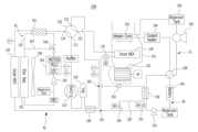
도 1은 본 발명에 따른 자동차용 히트펌프 시스템의 구성을 보여주는 구성도.
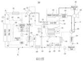
도 2는 본 발명의 히트펌프 시스템이 실내 냉방 모드로만 작동될 때의 냉매의 흐름을 보여주는 모식도.
도 3은 본 발명의 히트펌프 시스템이 실내 냉방 및 배터리 냉각 모드로 동시 작동될 때의 냉매 및 냉각수의 흐름을 보여주는 모식도.
도 4는 본 발명의 히트펌프 시스템이 실내 난방 모드로만 작동될 때의 냉매 및 냉각수의 흐름을 보여주는 모식도.
도 5는 본 발명의 히트펌프 시스템이 실내 난방 및 배터리 예열 모드로 동시 작동될 때의 냉매 및 냉각수의 흐름을 보여주는 모식도.1 is a configuration diagram showing the configuration of a heat pump system for an automobile according to the present invention.
Figure 2 is a schematic diagram showing the flow of refrigerant when the heat pump system of the present invention is operated only in indoor cooling mode.
Figure 3 is a schematic diagram showing the flow of refrigerant and coolant when the heat pump system of the present invention operates simultaneously in indoor cooling and battery cooling modes.
Figure 4 is a schematic diagram showing the flow of refrigerant and cooling water when the heat pump system of the present invention is operated only in indoor heating mode.
Figure 5 is a schematic diagram showing the flow of refrigerant and coolant when the heat pump system of the present invention is simultaneously operated in indoor heating and battery preheating modes.
아래에서는 첨부된 도면들을 참고로 하여 본 발명의 실시 예에 대하여 본 발명이 속하는 기술 분야에서 통상의 지식을 가진 자가 용이하게 실시할 수 있도록 상세히 설명한다.Below, with reference to the attached drawings, embodiments of the present invention will be described in detail so that those skilled in the art can easily implement the present invention.
그러나 본 발명은 여러 가지 상이한 형태로 구현될 수 있으며 여기에서 설명하는 실시 예에 국한되지 않는다. 또한, 상세한 설명 전반에 걸쳐서 동일한 참조번호로 표시된 부분들은 동일한 구성요소들을 의미함을 밝혀둔다.However, the present invention may be implemented in many different forms and is not limited to the embodiments described herein. In addition, it should be noted that parts indicated with the same reference numbers throughout the detailed description refer to the same components.
이하, 본 발명의 실시 예에 따른 자동차의 히트펌프 시스템에 대해 상세하게 설명하기로 한다.Hereinafter, a heat pump system for an automobile according to an embodiment of the present invention will be described in detail.
도 1은 본 발명의 실시 예에 따른 자동차용 히트펌프 시스템의 전체 구성을 보여주는 구성도이다.1 is a configuration diagram showing the overall configuration of a heat pump system for an automobile according to an embodiment of the present invention.
도 1을 참조하면, 본 발명은 압축기(110)로부터 토출되는 냉매의 흐름 방향을 제어하여 자동차 실내의 냉,난방을 수행하는 자동차용 히트펌프 시스템(100)에 있어서, 압축기(110), 냉매라인 4방밸브(120), 외부열교환기(130), 내부열교환기(140), 제1팽창밸브(170), 배터리 칠러(190), 제2팽창밸브(191)를 포함하여 구성되는 냉매순환라인(RL)과, 히터코어(103)와 냉각수 전기히터(104)를 구비하며 실내 난방을 위한 냉각수가 순환되는 실내 난방 냉각수 순환라인(CL)과, 냉매순환라인(RL)을 따라 이동하는 냉매와 자체 순환하는 냉각수와의 열교환을 통해 자동차에 탑재된 각종 전장부품에서 발생되는 열을 흡수하여 외부로 방출시키는 전장품 냉각수 순환라인(EL)과, 실내 난방 냉각수 순환라인(CL)과 냉각수라인 4방밸브(108)를 통해 선택적으로 연결되는 배터리 냉각수 순환라인(BL)과, 공조모드에 따라 압축기(110), 4방밸브(108,120), 냉각수 전기히터(104), 제1 및 제2팽창밸브(170, 191)의 동작을 각각 제어하는 제어부(Electric HVAC vehicle control unit, EHVCU)를 포함하여 구성되며, 특히, 공조모드가 배터리 예열 모드로 운용될 경우 실내 난방 냉각수 순환라인(CL)에 구비된 냉각수 전기히터(104)의 열원을 이용하여 냉각수를 가열하고, 가열된 고온의 고온의 냉각수를 냉각수라인 4방밸브(108)를 통해 배터리 냉각수 순환라인(BL) 측으로 전달하여 배터리의 예열을 수행하는 것을 특징으로 한다.Referring to FIG. 1, the present invention relates to a
냉매순환라인(RL)에 구비되는 압축기(110)는 냉매를 압축하여 토출하는 전동식 압축기로서, 제어부를 통해 압축기(110)의 RPM을 PID 제어(Proportional Integral Differential Control)함으로써 실내 냉방 또는 난방을 수행할 수 있다.The
냉매라인 4방밸브(120)는 압축기(110)로부터 토출되는 냉매를 공조모드에 따라 외부열교환기(130)로 전달하거나 내부열교환기(140)로 전달하는 구성으로, 제어부의 제어를 통해 냉매의 흐름을 특정 방향으로 유도할 수 있다.The refrigerant line four-
외부열교환기(130)는 압축기(110) 또는 내부열교환기(140)로부터 전달되는 냉매를 자동차 외부의 공기와 열교환시키는 기능을 하고, 내부열교환기(140)는 외부열교환기(130)에서 전달된 냉매를 탑승객이 위치한 실내로 공급되는 공기와 열교환시키거나, 압축기(110)에서 배출된 냉매를 실내로 공급되는 공기와 열교환시키는 기능을 한다.The
제1팽창밸브(170)는 내부열교환기(140)로 인입되거나 내부열교환기(140)로부터 인출되는 냉매라인 상에 설치되며, 제어부에서 전송되는 제어신호에 따라 작동되어 냉매를 팽창시킬 수 있다. 이때, 상기 제1팽창밸브(170)로는 PID 제어에 의해 개도량 조절이 가능한 전자식 팽창밸브(Electronic Expansion Valve; EEV)가 사용될 수 있다.The
전장품 냉각수 순환라인(EL)은 외부열교환기(130)와 인접된 영역에 설치되어, 공조모드에 따라 자동차에 탑재된 각종 전장부품(Motor, MCU, LDC, OBC 등)으로부터 발생되는 열을 흡수하여 외부로 배출하는 기능을 한다.The electrical component coolant circulation line (EL) is installed in an area adjacent to the external heat exchanger (130) and absorbs heat generated from various electrical components (motor, MCU, LDC, OBC, etc.) mounted on the vehicle depending on the air conditioning mode. It has the function of discharging to the outside.
전장품 냉각수 순환라인(EL)에는 외부열교환기(130)와 냉매라인 4방밸브(120) 사이에 장착되어 상기 외부열교환기(130)로부터 배출되는 냉매와 전장품 냉각수 유로(162)를 따라 유동하는 냉각수를 서로 열교환시키는 전장품 칠러(161)가 구비된다.The electrical equipment coolant circulation line (EL) is installed between the
전장품 냉각수 순환라인(EL)에서 전장품 냉각수 유로(162)는 전장품 칠러(161)와 전장품 라디에이터(163)를 연결하는 하나의 냉각수 유동 통로를 형성하며, 전장품 냉각수 유로(162)와 전장품 냉각수 바이패스 유로(167)의 교차 지점에는 전장품 냉각용 3방밸브(166)가 설치된다.In the electronic device coolant circulation line (EL), the electronic device
그리고, 전장품 냉각수 유로(162)에는 자동차에 탑재된 각종 전장부품으로부터 발생되는 열을 흡수하는 전장품 냉각수단(164)과, 냉각수의 일방향 유동을 발생시키는 전장품 냉각수 순환용 펌프(165)가 설치된다.In addition, in the electrical
또한, 전장품 라디에이터(163)는 외부열교환기(130)와 인접하게 장착되어 전장품 냉각수 유로(162)를 통해 유동하는 냉각수의 열을 방출시킨다. 이때, 전장품 냉각수 유로(162)를 따라 이동하는 냉각수가 전장품에서 발생된 열을 흡수하여 전장품 라디에이터(163)를 통해 외부로 방출시킬 수 있으며, 별도로 설치된 냉각팬(168)을 이용하여 외부로의 방열을 촉진시킬 수 있다.In addition, the
한편, 냉매의 흐름을 특정 방향으로 유도하는 냉매라인 4방밸브(120)는 제1포트(121), 제2포트(122), 제3포트(123) 및 제4포트(124)를 포함하여 구성된다.Meanwhile, the refrigerant line four-
구체적으로, 냉매라인 4방밸브의 제1포트(121)는 공조모드에 관계없이 항상 압축기(120)로부터 배출된 냉매가 인입되는 냉매 유입구이며, 제2포트(122)는 공조모드에 따라 제1포트(121) 또는 제3포트(123)에 선택적으로 연통되는 냉매 입출구로서, HVAC 모듈(101) 내부에 배치된 내부열교환기(140)와 연결된다.Specifically, the
그리고, 냉매라인 4방밸브의 제3포트(123)는 공조모드에 따라 제2포트(122)와 제4포트(124)에 선택적으로 연통되는 냉매 출구로서, 냉매 흐름상 압축기(110)의 상류측에 배치되는 중간열교환기(180)와 연결된다.In addition, the
또한, 냉매라인 4방밸브의 제4포트(122)는 공조모드에 따라 제1포트(121)와 제3포트(123)에 선택적으로 연통되는 냉매 입출구로서, 전장품 냉각수 순환라인(EL)의 전장품 칠러(161)와 연결된다.In addition, the
아울러, 상기 냉매라인 4방밸브의 각 포트들은 제1포트(121)가 제2포트(122)와 연통된 경우에는 제3포트(123)는 제4포트(124)와 연통되고, 제1포트(121)가 제4포트(124)와 연통된 경우에는 제2포트(122)는 제3포트(123)와 연통된다.In addition, when the
이에 따라, 상기 냉매라인 4방밸브의 제1포트(121)가 제4포트(124)와 연통되는 경우에는 압축기(110)로부터 배출된 냉매를 전장품 냉각수 순환라인(EL)의 전장품 칠러(161)로 전달하고, 제4포트(124)가 제3포트(123)와 연통되는 경우에는 전장품 냉각수 순환라인(EL)의 전장품 칠러(161)를 거쳐온 냉매를 냉매 흐름상 압축기(110)의 상류측에 배치되는 중간열교환기(180)로 전달한다.Accordingly, when the
한편, 외부열교환기(130)와 내부열교환기(140) 사이를 연결하는 냉매라인 상에는 외부열교환기(130)로부터 배출되는 냉매가 분기되거나 합류되는 제1분기점(181)이 마련되고, 냉매라인 4방밸브(120)의 제3포트(123)와 압축기(110) 사이를 연결하는 냉매라인 상에는 냉매라인 4방밸브(120)를 거쳐 나온 냉매와 배터리 칠러(190)를 거쳐 나온 냉매가 서로 합류되는 제2분기점(182)이 마련된다.Meanwhile, on the refrigerant line connecting the
이때, 상기 제2분기점(182)은 배터리 칠러(190)에서 나온 냉매의 과열도와 성능을 보다 증가시킬 수 있도록 중간열교환기(180) 이전 위치에 위치시키는 것이 바람직하다.At this time, the
그리고, 상기 제1분기점(181)과 제2분기점(182)을 연결하는 별도의 냉매분기라인 상에는 배터리 칠러(190)가 설치되고, 상기 배터리 칠러(190)의 상류측에는 냉매를 팽창시키는 제2팽창밸브(191)가 설치된다.In addition, a
또한, 배터리 냉각수 순환라인(BL)에는 냉각수 순환펌프(193), 배터리(194)가 구비되어 냉각수 순환용 펌프(193)를 통해 냉각수의 순환이 이루어지며, 배터리 냉각수 순환라인(BL) 내부를 순환하는 냉각수는 배터리 칠러(190)에서 냉매와 열교환됨으로써 배터리(194)의 냉각이 수행될 수 있다. 여기서, 상기 배터리 칠러(190)는 증발기의 역할을 수행하게 된다.In addition, the battery coolant circulation line (BL) is equipped with a
이와 같이, 외부열교환기(130)로부터 배출된 냉매의 일부를 제2팽창밸브(191)로 유입시켜 배터리 칠러(190)에서 배터리 냉각수 순환라인(BL) 내부를 따라 유동하는 냉각수와 열교환을 통해 배터리(194)를 냉각시킬 수 있다.In this way, a part of the refrigerant discharged from the
이 경우, 상기 배터리 칠러(190) 측에 설치되는 제2팽창밸브(191)는 솔레노이드 방식으로 온/오프(ON/OFF) 개폐동작만이 가능하고 개도량 조절이 불가능한 팽창밸브가 사용되거나, 또는 내부열교환기(140)의 상류측에 설치되는 제1팽창밸브(170)와 같이 PID 제어에 의해 개도량 조절이 가능한 전자식 팽창밸브(EEV)가 사용될 수 있다. 또한, 냉매가 배출되는 배터리 칠러(190)의 하류측 냉매라인 상에는 냉매의 역류를 방지하기 위한 체크밸브(192)가 장착될 수 있다.In this case, the
한편, 냉매순환라인(RL)에 있어서, 제1분기점(181)과 배터리 칠러(190)를 연결하는 냉매라인 상에는 내부열교환기(140)에서 배출되는 냉매의 일부가 제2팽창밸브(191)를 거치지 않고 우회(Bypass)하여 배터리 칠러(190) 측으로 곧바로 유입될 수 있도록 바이패스라인(183)이 설치될 수 있다.Meanwhile, in the refrigerant circulation line (RL), a portion of the refrigerant discharged from the
즉, 바이패스라인(183)은 제2팽창밸브(191)의 상류측 냉매라인의 일측으로부터 분기되어 배터리 칠러(190)와 제2팽창밸브(191) 사이에 위치한 냉매라인에 연결되는 구조로 설치되어, 공조모드에 따라 내부열교환기(140)에서 배출되는 냉매의 일부가 제1분기점(181)을 지나 바이패스라인(183)을 통해 우회하여 배터리 칠러(190) 측으로 곧바로 유입될 수 있다. 이 경우 제2팽창밸브(191)는 폐쇄(Close)되어 상기 제2팽창밸브(191)를 통한 배터리 칠러(190) 측으로의 냉매의 유입은 차단될 수 있다.That is, the
아울러, 바이패스라인(183)에는 상기 바이패스라인(183)으로의 냉매 유입을 선택적으로 허용할 수 있도록 제어부에 의해 개폐(Open/Close) 작동이 제어될 수 있는 바이패스밸브(184)가 설치될 수 있다. 또한, 상기 바이패스라인(183) 상에는 냉매가 역류되는 것을 방지할 수 있도록 체크밸브가 추가적으로 설치될 수 있다.In addition, the
이와 달리, 바이패스밸브(184)를 제1분기점(181)과 제2팽창밸브(191)를 연결하는 냉매라인과 바이패스라인(183)의 교차 지점에 3방밸브 방식으로 설치하여, 공조모드에 따라 제어부에 의한 3방밸브의 선택적 유로 변경을 통해 제2팽창밸브(191) 측으로 냉매의 흐름을 유도하거나 바이패스라인(183) 측으로 냉매의 흐름을 유도하도록 구성할 수도 있다.In contrast, the
한편, 중간열교환기(180)는 IHX(Intermediate Heat Exchanger)로도 약칭되는 구성으로서, 제1팽창밸브(170) 및 내부열교환기(140)를 통과하기 전의 냉매와 통과한 후의 냉매 간의 열교환을 위해 마련되는 구성이다.Meanwhile, the
이러한 중간열교환기(180)는 외부열교환기(130)와 내부열교환기(140) 사이를 연결하는 냉매라인의 제1분기점(181)과 외부열교환기(130) 사이에 장착되어, 공조모드에 따라 외부열교환기(130)로부터 배출되는 냉매를 열교환시킨 후 내부열교환기(140)에 전달하거나, 내부열교환기(140)로부터 배출되는 냉매를 열교환시킨 후 외부열교환기(130)에 전달하게 된다.This
이 경우, 상기 중간열교환기(180)는 제1팽창밸브(170) 측으로 냉매를 전달하는 외측관로와, 어큐뮬레이터(150)와 압축기(110) 측으로 냉매를 전달하는 내측관로를 포함하는 이중관 형태의 열교환기로 구성될 수 있다. 여기서 제1팽창밸브(170) 측에 연결된 외측관로에는 압력과 온도가 상대적으로 높은 냉매가 유동하며, 내측관로에는 압력과 온도가 상대적으로 낮은 냉매가 유동할 수 있다.In this case, the
한편, 자동차의 실내 난방을 위한 실내 난방 냉각수 순환라인(CL)에는 히터코어(103)와 냉각수 전기히터(104)와 냉각수 순환용 펌프(106)가 구비되어, 냉각수 전기히터(104)를 통해 가열된 냉각수를 히터코어(103)로 유입시켜 실내 난방을 위한 열원으로 사용될 수 있다.Meanwhile, the indoor heating coolant circulation line (CL) for indoor heating of a car is equipped with a
이 경우, HVAC 모듈(101) 내에 히터코어(103)를 배치하고, 히터코어(103)를 순환하는 냉각수 라인을 구성하되, 냉각수 라인 상에 냉각수 전기히터(104)와 펌프(105)와 냉각수 리저버 탱크(106)를 배치하여 구성할 수 있다.In this case, the
구체적으로, HVAC 모듈(101)의 내부에는 실내 난방 냉각수 순환라인(CL)에 구비된 냉각수 전기히터(104)에 의해 가열된 고온의 냉각수가 유입되는 히터코어(103)가 장착된다.Specifically, a
상기 히터코어(103)는 HVAC 모듈(101) 내부에서 내부열교환기(140)의 상부측에 장착되고, 내부열교환기(140)의 하부측에는 제어부를 통해 제어되며 내부열교환기(140) 측으로 공기를 송풍시킬 수 있는 블로워 팬(102)이 설치된다.The
따라서, 공조모드가 실내 난방 모드, 또는 제습 또는 제상 모드로 운용될 경우 히터코어(103)를 통해 자동차 실내로 공급되는 공기에 열을 가하여 실내 난방, 또는 제습 또는 제상을 수행할 수 있다. 이 경우, 상기 히터코어(103)로 공급되는 냉각수의 온도는 제어부에 의한 냉각수 전기히터(104)의 PID 제어를 통해 온도가 조절될 수 있다.Therefore, when the air conditioning mode is operated in an indoor heating mode or a dehumidifying or defrosting mode, heat can be applied to the air supplied to the car interior through the
또한, 히터코어(103) 측에는 히터코어(103)의 주변의 온도를 검출할 수 있는 온도센서가 설치되고, 상기 온도센서는 히터코어(103)가 설치되어 있는 HVAC 모듈(101) 내부 덕트(Duct)의 현재 온도를 검출하여 제어부로 전송할 수 있다. 그리고, 제어부에서는 온도센서를 통해 검출된 히터코어(103) 주변의 온도가 사용자에 의해 설정된 설정온도값에 오차범위 내로 도달될 때까지 냉각수 전기히터(104)를 PID 제어할 수 있다.In addition, a temperature sensor capable of detecting the temperature around the
한편, 제어부는 히트펌프 시스템(100)이 실내 냉방 모드로 운용될 경우, 사용자의 온도 설정에 따른 목표 증발기온과 현재 증발기온의 차이가 오차 범위에 수렴될 때까지 압축기(110)를 PID 제어함으로써 실내 냉방을 수행할 수 있다.Meanwhile, when the
즉, 히트펌프 시스템(100)이 실내 냉방 모드로 작동될 경우 내부열교환기(140)는 증발기로서 기능을 하게 되며, 제어부에서는 증발기 기능을 하는 내부열교환기(140)의 온도를 목표 증발기온으로 설정하고, 내부열교환기(140) 주변에 설치된 온도센서(미도시)를 통해 검출된 현재 증발기온과 상기 목표 증발기온의 차이가 기 설정된 오차 범위에 수렴될 때까지 압축기(110) RPM에 대한 PID 제어를 수행함으로써 실내 냉방을 수행할 수 있다.That is, when the
이와 반대로, 히트펌프 시스템(100)이 실내 난방 모드로 작동될 경우에는 내부열교환기(140)는 응축기로서 기능을 하게 되며, 제어부에서는 응축기 기능을 하는 내부열교환기(140)의 온도를 목표 온도로 설정하고, 온도센서를 통해 검출된 내부열교환기(140)의 현재 온도와 상기 목표 온도의 차이가 기 설정된 오차 범위에 수렴될 때까지 압축기(110) RPM에 대한 PID 제어를 수행함으로써 실내 난방을 수행할 수 있다.On the contrary, when the
아울러, 상기 제어부에서는 히터코어(103)의 온도를 목표 온도로 설정하고, 온도센서를 통해 검출된 히터코어(103)의 현재 온도와 상기 목표 온도의 차이가 기 설정된 오차 범위에 수렴될 때까지 냉각수 전기히터(104)에 대한 PID 제어를 수행함으로써 실내 난방을 수행할 수 있다.In addition, the control unit sets the temperature of the
한편, 본 발명의 히트펌프 시스템(100)은 실내 난방 모드로 운용될 경우, 압축기(110)에서 내부열교환기(140)로 유입되는 고온의 냉매와, 냉각수 전기히터(104)를 통해 가열되어 히터코어(103)로 유입되는 고온의 냉각수의 2가지 열원을 이용하여 실내 난방을 수행할 수 있다.Meanwhile, when the
이와 함께, 외기 온도가 낮을 경우 배터리(194)의 충전속도를 높일 수 있도록 배터리(194)를 일정온도까지 예열시키는 배터리 예열 모드로 운용될 수 있다. 이를 위해 기존의 히트펌프 시스템에는 배터리 냉각수 순환라인 상에 배터리 히터(Battery heater)가 별도 설치되어, 배터리 예열 모드로 작동될 경우 상기 배터리 히터에서 발생되는 열원을 이용하여 배터리의 예열을 수행하였다.In addition, when the outside temperature is low, the
그러나, 기존의 히트펌프 시스템은 실내 난방 냉각수 순환라인에 실내 난방용 냉각수의 가열을 위해 냉각수 전기히터를 설치하고, 배터리 냉각수 순환라인 상에 배터리의 예열을 위한 배터리 히터가 각각 개별적으로 구비되는 구성으로 이루어져 있다. 이 경우 냉각수 전기히터는 제어부의 제어를 통해 발열량 조절이 가능하지만, 배터리 히터는 발열량 조절이 불가능한 별도의 히터를 사용하고 있었기 때문에, 겨울철 배터리의 예열을 위한 전력 사용량도 그만큼 많아져서 결국 자동차의 연비 저하를 초래하는 문제가 있었다.However, the existing heat pump system consists of installing an electric coolant heater in the indoor heating coolant circulation line to heat the indoor heating coolant, and separately providing battery heaters for preheating the battery in the battery coolant circulation line. there is. In this case, the coolant electric heater can control the heat output through the control of the control unit, but since the battery heater used a separate heater whose heat output cannot be adjusted, the amount of power used to preheat the battery in winter increases accordingly, ultimately reducing the car's fuel efficiency. There was a problem that resulted in .
이와 같은 문제점을 개선하고자, 본 발명의 히트펌프 시스템(100)에서는 실내 난방 냉각수 순환라인(CL)에 설치되어 있는 발열량 조절이 가능한 냉각수 전기히터(104)를 통해 냉각수를 가열하고, 가열된 고온의 냉각수를 냉각수라인 4방밸브(108)를 통해 배터리 냉각수 순환라인(BL)으로 전달하여 배터리(194)를 가열해 줌으로써 기존과 같이 배터리 냉각수 순환라인 상에 별도의 배터리 히터를 사용하지 않고서도 배터리 예열작업이 가능한 히트펌프 시스템 구조를 제공하고 있다.In order to improve this problem, the
이를 위해, 본 발명의 히트펌프 시스템(100)에는 실내 난방 냉각수 순환라인(CL)과 배터리 냉각수 순환라인(BL) 사이에 제어부의 제어를 통해 내부 유로의 선택적 변경이 가능한 냉각수라인 4방밸브(108)가 설치되어, 공조모드에 따라 상기 냉각수라인 4방밸브(108) 내부의 유로 변경을 통해 실내 난방 냉각수 순환라인(CL)과 배터리 냉각수 순환라인(BL)이 선택적으로 연결되도록 구성하고, 히트펌프 시스템(100)의 공조모드가 배터리 예열 모드로 운용될 경우, 제어부는 냉각수라인 4방밸브(108)의 내부 유로를 제어하여 실내 난방 냉각수 순환라인(CL)과 배터리 냉각수 순환라인(BL)을 연결시켜 실내 난방 냉각수 순환라인(CL)과 배터리 냉각수 순환라인(BL) 간의 냉각수의 순환이 이루어지도록 함으로써, 냉각수 전기히터(104)를 통해 가열된 고온의 냉각수를 냉각수라인 4방밸브(108)를 통해 배터리 냉각수 순환라인(BL) 측으로 전달하여 배터리(194)의 예열을 수행할 수 있다.To this end, the
따라서, 기존의 히트펌프 시스템과 같이 배터리 냉각수 순환라인에 배터리 가열을 위한 배터리 히터를 추가 설치할 필요가 없기 때문에 설치 부품수를 감소시켜 제품의 제조원가를 절감시킬 수 있는 효과를 얻을 수 있다.Therefore, since there is no need to install an additional battery heater for heating the battery in the battery coolant circulation line like in the existing heat pump system, the manufacturing cost of the product can be reduced by reducing the number of installed parts.
이하에서는 본 발명에 따른 자동차용 히트펌프 시스템(100)의 각 공조모드에 대해서 상세히 설명하기로 한다.Hereinafter, each air conditioning mode of the automotive
도 2 내지 도 5에는 본 발명의 실시 예에 따른 자동차용 히트펌프 시스템(100)이 실내 냉방 모드, 실내 냉방 및 배터리 냉각 모드, 실내 난방 모드, 실내 난방 및 배터리 예열 모드로 각각 운용될 경우에 냉매 및 냉각수의 흐름이 도시되어 있다.2 to 5 show refrigerant when the automotive
먼저, 도 2에 도시된 실내 냉방 모드의 경우에 대해 설명하기로 한다.First, the case of the indoor cooling mode shown in FIG. 2 will be described.
본 발명의 히트펌프 시스템(100)이 실내 냉방 모드로만 운용될 경우 냉매순환라인(RL) 내에서의 냉매의 흐름은 "압축기(110) - 냉매라인 4방밸브(120) - 전장품 칠러(161) - 외부열교환기(130, 응축기로 기능) - 중간열교환기(180) - 내부열교환기(140, 증발기로 기능) - 냉매라인 4방밸브(120) - 중간열교환기(180) - 어큐뮬레이터(150) - 압축기(110)" 순으로 순환된다.When the
이와 같은 실내 냉방 모드에 있어서 냉매라인 4방밸브(120)는, 압축기(110)로부터 배출되는 냉매가 외부열교환기(130)로 인입되고 내부열교환기(140)로부터 배출되는 냉매가 압축기(110)로 인입되도록 냉매라인 4방밸브(120)의 제1포트(121)가 제4포트(124)와 연통되고, 제2포트(122)는 제3포트(123)와 연통될 수 있다.In this indoor cooling mode, the refrigerant line four-
그리고, 외부열교환기(130)로부터 나온 냉매는 중간열교환기(180)를 경유하여 제1분기점(181)을 기점으로 일부가 내부열교환기(140) 측으로 유입되고, 다른 일부가 배터리 칠러(190)로 유입될 수 있다.In addition, part of the refrigerant from the external heat exchanger (130) flows into the internal heat exchanger (140) starting from the first branch point (181) via the intermediate heat exchanger (180), and the other part flows into the battery chiller (190). may be introduced.
이 경우, 내부열교환기(140) 측으로 향하는 냉매는 제1팽창밸브(170)를 거쳐 팽창된 후 내부열교환기(140)로 유입되고, 이렇게 유입되는 저온의 냉매는 내부열교환기(140)에서 자동차의 실내로 송풍되는 공기와 열교환되어, 열교환된 저온 상태의 공기가 실내로 공급됨으로써 실내 냉방이 이루어질 수 있다.In this case, the refrigerant heading toward the
이와 같이 히트펌프 시스템(100)이 실내 냉방 모드로만 작동되는 경우에는 실내 난방 냉각수 순환라인(CL)과 전장품 냉각수 순환라인(EL)과 배터리 냉각수 순환라인(BL)에 구비되는 각 펌프(105,165,193)의 작동이 중지되므로 상기 각 냉각수 순환라인(CL,EL,BL) 내부에서의 냉각수 흐름은 발생하지 않는다.In this way, when the
그리고, 실내 난방 냉각수 순환라인(CL)과 배터리 냉각수 순환라인(BL) 사이에 위치된 냉각수라인 4방밸브(108)는 실내 난방 냉각수 순환라인(CL)과 배터리 냉각수 순환라인(BL) 사이의 연결을 차단시키도록 제어됨으로써 실내 난방 냉각수 순환라인(CL)과 배터리 냉각수 순환라인(BL) 간의 냉각수 순환은 이루어지지 않게 된다.In addition, the cooling water line four-
또한, 냉매순환라인(RL)에 있어 바이패스밸브(184)는 폐쇄(Close)되고 제2팽창밸브(191)는 개방(Open)되어 외부열교환기(130)에서 나온 냉매가 제2팽창밸브(191)를 거쳐 배터리 칠러(190) 측으로 유입된 후 압축기(110) 측으로 유입되는 유동 순환이 이루어지도록 제어될 수 있다.In addition, in the refrigerant circulation line (RL), the
또는, 바이패스밸브(184) 및 제2팽창밸브(191)를 모두 폐쇄(Close)시켜 외부열교환기(130)에서 나온 냉매가 배터리 칠러(190) 측으로 유입되지 않고 곧바로 내부열교환기(140) 측으로 유입된 후 압축기(110) 측으로 배출되는 유동 순환이 이루어지도록 제어될 수도 있다.Alternatively, both the
다음으로, 도 3을 참조하여 본 발명의 히트펌프 시스템이 실내 냉방 및 배터리 냉각 모드로 동시 작동되는 경우에 대해 설명하기로 한다.Next, with reference to FIG. 3, a case where the heat pump system of the present invention is simultaneously operated in indoor cooling and battery cooling modes will be described.
히트펌프 시스템(100)이 실내 냉방 모드와 배터리 냉각 모드로 동시 운용될 경우 냉매의 흐름은 "압축기(110) - 냉매라인 4방밸브(120) - 전장품 칠러(161) - 외부열교환기(130, 응축기로 기능)- 중간열교환기(180) - 내부열교환기(140, 증발기로 기능) - 냉매라인 4방밸브(120) - 어큐뮬레이터(150) - 압축기(110)"순으로 유동 순환이 이루어지게 된다.When the heat pump system (100) is operated simultaneously in indoor cooling mode and battery cooling mode, the flow of refrigerant is as follows: "compressor (110) - refrigerant line 4-way valve (120) - electronics chiller (161) - external heat exchanger (130, The flow circulation occurs in the following order: - intermediate heat exchanger (180) - internal heat exchanger (140, functioning as an evaporator) - refrigerant line 4-way valve (120) - accumulator (150) - compressor (110).
이와 같이 실내 냉방 및 배터리 냉각 모드로 동시 작동될 경우에는, 외부열교환기(130)로부터 나온 냉매는 중간열교환기(180)를 경유하여 제1분기점(181)을 기점으로 일부가 내부열교환기(140) 측으로 유입되고, 다른 일부는 배터리 칠러(190) 측으로 유입될 수 있다.In this way, when operating simultaneously in room cooling and battery cooling mode, the refrigerant from the external heat exchanger (130) passes through the intermediate heat exchanger (180) and a portion of the refrigerant is transferred to the internal heat exchanger (140) starting from the first branch point (181). Some may flow into the side, and some may flow into the
이때, 내부열교환기(140) 측으로 유입되는 저온 상태의 냉매는 실내로 송풍되는 공기와 열교환됨으로써, 열교환된 저온 상태의 공기가 실내로 공급되어 실내 냉방이 이루어질 수 있다.At this time, the low-temperature refrigerant flowing into the
또한, 배터리 칠러(190) 측으로 향하는 냉매라인에서는 바이패스밸브(184)가 폐쇄(Close)되고 제2팽창밸브(191)가 개방(Open)됨으로써, 외부열교환기(130)에서 나온 냉매의 일부가 제2팽창밸브(191)를 통해 배터리 칠러(190) 측으로 유입된 후 제2분기점(182)에서 내부열교환기(140)를 거쳐 나온 냉매와 합류하여 압축기(110)로 유입될 수 있다.In addition, in the refrigerant line heading toward the
이 과정에서 배터리 칠러(190)에 유입되는 저온의 냉매와 배터리 냉각수 순환라인(BL) 내부를 순환하는 냉각수와 서로 열교환되어 저온 상태로 만들어진 냉각수를 통해 배터리(194)의 냉각작업이 수행될 수 있다. 이때, 냉각수라인 4방밸브(108)는 실내 난방 냉각수 순환라인(CL)과 배터리 냉각수 순환라인(BL) 사이의 연결을 차단시키도록 내부유로가 제어될 수 있다.In this process, cooling of the
이와 같이 외부열교환기(130)를 지나며 응축된 냉매가 제1팽창밸브(170)와 제2팽창밸브(191)을 거쳐 팽창하여 저온의 냉매로 내부열교환기(140)와 배터리 칠러(190)로 각각 유입됨으로써, HVAC 모듈(101)에 유입된 공기를 냉각시켜 실내 냉방을 수행하는 동시에 배터리 칠러(190)에 유입된 저온 냉매의 열교환 작용에 의해 배터리(194)를 냉각시킬 수 있다.In this way, the refrigerant condensed as it passes through the
다음으로, 도 4에 도시된 실내 난방 모드의 경우에 대해 설명하기로 한다.Next, the case of the indoor heating mode shown in FIG. 4 will be described.
본 발명의 히트펌프 시스템(100)이 실내 난방 모드로만 운용될 경우 냉매순환라인(RL) 내에서의 냉매의 흐름은, "압축기(110) - 냉매라인 4방밸브(120) - 내부열교환기(140, 응축기로 기능) - 외부열교환기(130, 증발기로 기능) - 전장품 칠러(161) - 냉매라인 4방밸브(120) - 중간 열교환기(180) - 어큐뮬레이터(150) - 압축기(110)" 순으로 냉매의 유동 순환이 이루어질 수 있다.When the
이 경우, 냉매라인 4방밸브(120)는 압축기(110)로부터 배출되는 냉매가 내부열교환기(140)로 유입되고, 외부열교환기(130)로부터 배출되는 냉매가 압축기(110)로 유입되도록, 냉매라인 4방밸브(120)의 제1포트(121)가 제2포트(122)와 연통되고, 제3포트(122)는 제4포트(123)와 연통될 수 있다.In this case, the refrigerant line four-
이와 같이 히트펌프 시스템이 실내 난방 모드로 운용될 경우에는, 내부열교환기(140)는 응축기로 기능하게 되며, 상기 내부열교환기(140)로 유입된 고온의 냉매는 실내로 송풍되는 공기와 열교환되고, 냉매와 열교환된 고온 상태의 공기가 실내로 공급되어 실내 난방이 이루어질 수 있다.In this way, when the heat pump system is operated in indoor heating mode, the
또한, 필요에 따라 실내 난방 냉각수 순환라인(CL)에서는 자동차 실내로 공급되는 공기에 추가적인 열을 가할 수 있도록 냉각수 전기히터(104)를 작동시켜 냉각수를 가열하여 히터코어(103)에 공급함으로써 난방 성능을 향상시킬 수 있다.In addition, when necessary, the indoor heating coolant circulation line (CL) operates the coolant
이와 같이 히트펌프 시스템이 실내 난방 모드로 작동되는 상황은 실외 온도가 낮은 동절기로서, 일반적인 경우에는 배터리를 냉각시킬 필요가 없기 때문에, 바이패스밸브(184) 및 제2팽창밸브(191)을 폐쇄(Close)시켜 배터리 칠러(190) 측으로 냉매가 유동되지 않도록 할 수 있다.In this way, the situation in which the heat pump system is operated in indoor heating mode is winter when the outdoor temperature is low. In general, there is no need to cool the battery, so the
또는, 도 4에 도시된 실시 예 형태와 같이 냉매순환라인(RL)의 바이패스밸브(184)를 개방(Open)하고 제2팽창밸브(191)를 폐쇄(Close)시켜 내부열교환기(140)에서 나온 냉매의 일부가 바이패스라인(183)을 통해 배터리 칠러(190) 측으로 유입된 후 압축기(110)로 공급되도록 제어될 수도 있다. 이 경우, 냉각수라인 4방밸브(108)는 실내 난방 냉각수 순환라인(CL)과 배터리 냉각수 순환라인(BL) 사이의 연결을 차단시키도록 제어됨으로써 실내 난방 냉각수 순환라인(CL) 내부를 순환하는 냉각수를 통해서만 실내 난방이 이루어지도록 제어될 수 있다.Alternatively, as shown in the embodiment shown in FIG. 4, the
다음으로, 도 5를 참조하여, 본 발명의 히트펌프 시스템이 실내 난방 및 배터리 예열 모드로 동시 작동되는 경우에 대해 설명하기로 한다.Next, with reference to FIG. 5, a case where the heat pump system of the present invention is simultaneously operated in room heating and battery preheating modes will be described.
히트펌프 시스템(100)이 실내 난방 및 배터리 예열 모드로 동시에 운용될 경우, 냉매순환라인(RL) 내에서의 냉매의 흐름은, "압축기(110) - 냉매라인 4방밸브(120) - 내부열교환기(140, 응축기로 기능) - 외부열교환기(130, 증발기로 기능) - 전장품 칠러(161) - 냉매라인 4방밸브(120) - 중간 열교환기(180) - 어큐뮬레이터(150) - 압축기(110)" 순으로 냉매의 유동 순환이 이루어질 수 있다.When the
이와 같이 히트펌프 시스템(100)이 실내 난방 및 배터리 예열 모드로 동시 운용될 경우, 내부열교환기(140)는 응축기로서 기능을 하게 되며, 내부열교환기(140)로 유입된 고온 상태의 냉매는 실내로 송풍되는 공기와 열교환되어, 냉매와 열교환된 고온의 공기가 실내로 공급되어 실내 난방이 이루어질 수 있다.In this way, when the
또한, 실내 난방 강도를 추가적으로 높이고자 할 경우에는 실내 난방 냉각수 순환라인(CL)의 냉각수 전기히터(104)를 작동시켜 냉각수를 가열하고, 가열된 냉각수를 히터코어(103)에 공급하여 송풍 공기와 열교환시켜 실내로 공급함으로써 난방 성능을 향상시킬 수 있다.In addition, when it is desired to further increase the indoor heating intensity, the coolant
이와 같이 히트펌프 시스템이 실내 난방 모드로 작동될 경우는 일반적으로 실외 온도가 낮은 동절기이기 때문에, 낮은 외기 온도에 의해 배터리(194)의 충전현저하게 속도가 저하될 수 있다. 이 때문에 외기 온도가 낮을 경우 배터리(194)의 충전속도를 높일 수 있도록 배터리(194)를 가열하여 일정온도까지 예열시키는 작업이 필요하다.When the heat pump system is operated in the indoor heating mode, the charging speed of the
따라서, 본 발명에서는 히트펌프 시스템(100)이 배터리 예열 모드로 작동될 경우에 실내 난방 냉각수 순환라인(CL)에 설치된 냉각수 전기히터(104)를 이용하여 냉각수를 가열하고, 가열된 냉각수를 배터리 냉각수 순환라인(BL)으로 전달하여 배터리(194)를 예열시킬 수 있도록 구성되어 있다.Therefore, in the present invention, when the
즉, 냉각수라인 4방밸브(108)의 내부유로를 제어하여 실내 난방 냉각수 순환라인(CL)과 배터리 냉각수 순환라인(BL)을 서로 연결시켜 실내 난방 냉각수 순환라인(CL)과 배터리 냉각수 순환라인(BL) 간에 냉각수의 순환이 이루어지도록 하고, 냉각수 전기히터(104)를 통해 가열된 고온의 냉각수가 배터리 냉각수 순환라인(BL) 측으로 전달되어 고온의 냉각수에 의해 배터리(194) 예열이 수행될 수 있다.That is, by controlling the internal flow path of the coolant line 4-
또한, 냉매순환라인(RL)에 있어서 바이패스밸브(184)를 개방(Open)시키고 제2팽창밸브(191)를 폐쇄(Close)시켜 내부열교환기(140)에서 나온 냉매의 일부가 바이패스라인(183)을 통해 배터리 칠러(190) 측으로 유입되어 배터리 냉각수 순환라인(BL)을 따라 이동하는 냉각수와 열교환된 후 압축기(110)로 공급되도록 제어될 수 있다.In addition, in the refrigerant circulation line (RL), the
이 경우, 내부열교환기(140)에서 나와 배터리 칠러(190) 측으로 이동하는 냉매는 제2팽창밸브(191)로 유입되지 않고 바이패스라인(183)을 통해 배터리 칠러(190) 측으로 곧바로 유입되어 냉매의 온도 저하가 발생하지 않기 때문에 배터리 칠러(190)에서 냉매와 냉각수과 열교환이 이루어지더라도 냉각수의 온도가 크게 저하되지 않은 상태로 히터코어(103) 측으로 전달될 수 있고, 이에 따라 냉각수 전기히터(104)를 통해 냉각수를 과도하게 과열할 필요가 없다.In this case, the refrigerant coming out of the
이와 같이, 히트펌프 시스템(100)이 배터리 예열 모드로 운용될 경우에 실내 난방 냉각수 순환라인(CL)에 설치되어 있는 발열량 조절이 가능한 냉각수 전기히터(104)를 통해 냉각수를 가열하고, 가열된 고온의 냉각수를 냉각수라인 4방밸브(108)를 통해 배터리 냉각수 순환라인(BL)으로 전달하여 배터리(194)를 예열시킴으로써 기존 방식처럼 배터리 냉각수 순환라인 상에 별도의 배터리 히터를 설치하지 않고서도 배터리 예열을 원활하게 수행하는 것이 가능해질 수 있다. 따라서, 겨울철 배터리의 예열을 위한 배터리 전력 사용량도 그만큼 절감시킬 수 있기 때문에 자동차의 연비를 향상시킬 수 있는 효과를 얻을 수 있는 것이다.In this way, when the
이상에서는 본 발명의 바람직한 실시 예를 설명하였으나, 본 발명의 범위는 이같은 특정 실시 예에만 한정되지 않으며, 해당분야에서 통상의 지식을 가진 자라면 본 발명의 특허청구범위 내에 기재된 범주 내에서 적절하게 변경이 가능할 것이다Although preferred embodiments of the present invention have been described above, the scope of the present invention is not limited to these specific embodiments, and those skilled in the art can make appropriate changes within the scope described in the claims of the present invention. this will be possible
100: 히트펌프 시스템101: HVAC 모듈
102: 블로워 팬(Blower fan)103: 히터코어
104: 냉각수 전기히터105,165,193: 펌프
108 : 냉각수라인 4방밸브110: 압축기
120 : 냉매라인 4방밸브130: 외부열교환기
140: 내부열교환기150: 어큐뮬레이터
161: 전장품 칠러162: 전장품 냉각수 유로
163: 전장품 라디에이터168: 냉각팬
170: 제1팽창밸브180: 중간열교환기
183 : 바이패스라인184 : 바이패스밸브
190: 배터리 칠러191: 제2팽창밸브
192: 체크밸브100: Heat pump system 101: HVAC module
102: Blower fan 103: Heater core
104: Coolant electric heater 105,165,193: Pump
108: Coolant line 4-way valve 110: Compressor
120: Refrigerant line 4-way valve 130: External heat exchanger
140: Internal heat exchanger 150: Accumulator
161: Electrical equipment chiller 162: Electrical equipment coolant flow path
163: Electronic radiator 168: Cooling fan
170: first expansion valve 180: intermediate heat exchanger
183: bypass line 184: bypass valve
190: Battery chiller 191: Second expansion valve
192: check valve
Claims (10)
Translated fromKorean자동차의 실내 난방을 위한 실내 난방 냉각수 순환라인 내부를 순환하는 냉각수를 가열해 주는 냉각수 전기히터와;
상기 압축기와 외부열교환기와 내부열교환기가 구비된 냉매순환라인 내부를 순환하는 냉매와 배터리 냉각수 순환라인 내부를 순환하는 냉각수를 열교환시켜 배터리를 냉각하는 배터리 칠러와;
상기 배터리 칠러의 상류측에 위치한 냉매라인 상에 설치되는 팽창밸브와;
상기 실내 난방 냉각수 순환라인과 상기 배터리 냉각수 순환라인 사이에 설치되며, 공조모드에 따라 상기 실내 난방 냉각수 순환라인과 상기 배터리 냉각수 순환라인 사이를 선택적으로 연결하는 냉각수라인 4방밸브와;
상기 냉각수 전기히터와 상기 냉각수라인 4방밸브를 제어하는 제어부;를 포함하고,
상기 냉매순환라인은,
상기 팽창밸브의 냉매라인에서 분기되어 상기 배터리 칠러의 입구 측에 연결 설치되는 바이패스라인과;
상기 제어부에 의해 개폐(Open/Close)가 제어되며, 상기 바이패스라인 측으로의 냉매 이동을 선택적으로 허용하는 바이패스밸브;를 포함하며,
상기 바이패스라인에는 냉매의 역류를 방지할 수 있는 체크밸브가 설치되고,
상기 제어부를 통해 제어되며, 상기 압축기로부터 토출되는 냉매를 상기 외부열교환기로 전달하거나 상기 내부열교환기로 전달하는 냉매라인 4방밸브를 포함하며,
상기 외부열교환기와 상기 내부열교환기 사이를 연결하는 상기 냉매순환라인 상에는 상기 외부열교환기로부터 배출되는 냉매가 분기되거나 합류되는 제1분기점이 마련되고,
상기 냉매라인 4방밸브의 제3포트와 상기 압축기 사이를 연결하는 상기 냉매순환라인 상에는 상기 냉매라인 4방밸브를 거쳐 나온 냉매와 상기 배터리 칠러를 거쳐 나온 냉매가 서로 합류되는 제2분기점이 마련되고,
상기 제1분기점과 상기 제2분기점을 연결하는 냉매라인 상에 상기 배터리 칠러가 설치되는 것을 특징으로 하는 자동차용 히트펌프 시스템.
In the automotive heat pump system that performs cooling and heating of the vehicle interior by controlling the flow direction of the refrigerant discharged from the compressor,
A coolant electric heater that heats the coolant circulating inside the interior heating coolant circulation line for heating the interior of the car;
a battery chiller that cools the battery by heat exchanging refrigerant circulating inside the refrigerant circulation line equipped with the compressor, external heat exchanger, and internal heat exchanger and coolant circulating inside the battery coolant circulation line;
an expansion valve installed on a refrigerant line located upstream of the battery chiller;
a four-way cooling water line valve installed between the indoor heating coolant circulation line and the battery coolant circulation line, and selectively connecting the indoor heating coolant circulation line and the battery coolant circulation line according to an air conditioning mode;
It includes a control unit that controls the coolant electric heater and the coolant line four-way valve,
The refrigerant circulation line is,
a bypass line branched from the refrigerant line of the expansion valve and connected to the inlet side of the battery chiller;
It includes a bypass valve whose opening/closing is controlled by the control unit and which selectively allows movement of refrigerant to the bypass line side,
A check valve is installed in the bypass line to prevent backflow of refrigerant,
It is controlled through the control unit and includes a refrigerant line four-way valve that transfers the refrigerant discharged from the compressor to the external heat exchanger or to the internal heat exchanger,
A first branch point is provided on the refrigerant circulation line connecting the external heat exchanger and the internal heat exchanger, where the refrigerant discharged from the external heat exchanger branches or merges,
On the refrigerant circulation line connecting the third port of the refrigerant line 4-way valve and the compressor, a second branch point is provided where the refrigerant passing through the refrigerant line 4-way valve and the refrigerant passing through the battery chiller merge with each other, ,
A heat pump system for an automobile, wherein the battery chiller is installed on a refrigerant line connecting the first branch point and the second branch point.
The method of claim 1, wherein when the air conditioning mode is operated in a battery preheating mode, the control unit controls the flow path of the coolant line four-way valve to connect the indoor heating coolant circulation line and the battery coolant circulation line to each other, A heat pump system for an automobile, characterized in that it performs battery preheating by transferring high-temperature coolant heated through a coolant electric heater to the battery coolant circulation line through the coolant line four-way valve.
상기 냉각수라인 4방밸브를 통해 상기 실내 난방 냉각수 순환라인과 배터리 냉각수 순환라인 사이의 연결이 차단되며,
상기 바이패스밸브는 폐쇄(Close)되고 상기 팽창밸브는 개방(Open)되어,
상기 외부열교환기에서 나온 냉매가 상기 팽창밸브를 통해 배터리 칠러 측으로 유입되는 것을 특징으로 하는 자동차용 히트펌프 시스템.
The method of claim 1, wherein when the air conditioning mode is operated in an indoor cooling mode,
The connection between the indoor heating coolant circulation line and the battery coolant circulation line is blocked through the coolant line 4-way valve,
The bypass valve is closed and the expansion valve is open,
A heat pump system for an automobile, wherein the refrigerant from the external heat exchanger flows into the battery chiller through the expansion valve.
상기 냉각수라인 4방밸브를 통해 상기 실내 난방 냉각수 순환라인과 배터리 냉각수 순환라인 사이의 연결이 차단되며,
상기 바이패스밸브는 개방(Open)되고 상기 팽창밸브는 폐쇄(Close)되어,
상기 내부열교환기에서 나온 냉매가 상기 바이패스라인을 통해 배터리 칠러 측으로 유입되는 것을 특징으로 하는 자동차용 히트펌프 시스템.
The method of claim 1, wherein when the air conditioning mode is operated in an indoor heating mode,
The connection between the indoor heating coolant circulation line and the battery coolant circulation line is blocked through the coolant line 4-way valve,
The bypass valve is open and the expansion valve is closed,
A heat pump system for an automobile, wherein the refrigerant from the internal heat exchanger flows into the battery chiller through the bypass line.
상기 냉각수라인 4방밸브를 통해 상기 실내 난방 냉각수 순환라인과 배터리 냉각수 순환라인 사이의 연결이 차단되며,
상기 바이패스밸브는 폐쇄(Close)되고 상기 팽창밸브는 개방(Open)되어,
상기 외부열교환기에서 나온 냉매가 상기 팽창밸브를 통해 배터리 칠러 측으로 유입되어 상기 배터리 냉각수 순환라인을 순환하는 냉각수와 열교환을 통해 배터리의 냉각이 수행되는 것을 특징으로 하는 자동차용 히트펌프 시스템.
The method of claim 1, wherein when the air conditioning mode is operated in indoor cooling and battery cooling mode,
The connection between the indoor heating coolant circulation line and the battery coolant circulation line is blocked through the coolant line 4-way valve,
The bypass valve is closed and the expansion valve is open,
A heat pump system for an automobile, wherein the refrigerant from the external heat exchanger flows into the battery chiller through the expansion valve and cools the battery through heat exchange with coolant circulating in the battery coolant circulation line.
상기 바이패스밸브는 개방(Open)되고 상기 팽창밸브는 폐쇄(Close)되어, 상기 내부열교환기에서 나온 냉매가 상기 바이패스라인을 통해 배터리 칠러 측으로 유입되고,
상기 냉각수라인 4방밸브를 통해 상기 실내 난방 냉각수 순환라인과 배터리 냉각수 순환라인이 서로 연결되어, 상기 냉각수 전기히터를 통해 가열된 고온의 냉각수가 상기 배터리 냉각수 순환라인 측으로 전달되어 배터리 예열이 수행되는 것을 특징으로 하는 자동차용 히트펌프 시스템.
The method of claim 1, wherein when the air conditioning mode is operated in indoor heating and battery preheating mode,
The bypass valve is open and the expansion valve is closed, so that the refrigerant from the internal heat exchanger flows into the battery chiller through the bypass line,
The room heating coolant circulation line and the battery coolant circulation line are connected to each other through the coolant line 4-way valve, and the high-temperature coolant heated through the coolant electric heater is delivered to the battery coolant circulation line to preheat the battery. Characterized by a heat pump system for automobiles.
The method of claim 1, wherein a heater core through which coolant heated by the electric coolant heater flows is installed on the indoor heating coolant circulation line, and the heater core is mounted on the upper side of the internal heat exchanger inside the HVAC module, and the blower fan A heat pump system for an automobile, characterized in that it performs indoor heating through heat exchange with air blown through.
상기 전장품 냉각수 순환라인에는,
상기 외부열교환기와 냉매라인 4방밸브 사이에 장착되어 상기 외부열교환기로부터 배출되는 냉매와 전장품 냉각수 유로를 따라 유동하는 냉각수를 서로 열교환시키는 전장품 칠러와;
상기 외부열교환기와 인접하게 장착되어 상기 전장품 냉각수 유로를 통해 유동하는 냉각수의 열을 방출시키는 전장품 라디에이터와;
상기 전장품 냉각수 유로와 전장품 냉각수 바이패스 유로의 교차 지점에 설치되는 3방밸브와;
상기 전장품 라디에이터로 공기를 송풍하여 방열을 촉진시키는 냉각팬;이 구비되는 것을 특징으로 하는 자동차용 히트펌프 시스템.The electronic device coolant circulation line of claim 1, which absorbs heat generated from various electrical components mounted on the vehicle and discharges it to the outside through heat exchange between the refrigerant moving along the refrigerant circulation line and the coolant that circulates itself. And
In the electrical equipment coolant circulation line,
an electrical equipment chiller mounted between the external heat exchanger and the refrigerant line 4-way valve to exchange heat between the refrigerant discharged from the external heat exchanger and the coolant flowing along the electrical equipment coolant flow path;
an electrical equipment radiator that is mounted adjacent to the external heat exchanger and dissipates heat from coolant flowing through the electrical equipment coolant passage;
a three-way valve installed at an intersection of the electrical equipment coolant flow path and the electrical equipment coolant bypass flow path;
A heat pump system for an automobile, characterized in that it is provided with a cooling fan that blows air to the electrical equipment radiator to promote heat dissipation.
Priority Applications (1)
| Application Number | Priority Date | Filing Date | Title |
|---|---|---|---|
| KR1020220004844AKR102577144B1 (en) | 2022-01-12 | 2022-01-12 | Automotive heat pump system |
Applications Claiming Priority (1)
| Application Number | Priority Date | Filing Date | Title |
|---|---|---|---|
| KR1020220004844AKR102577144B1 (en) | 2022-01-12 | 2022-01-12 | Automotive heat pump system |
Publications (2)
| Publication Number | Publication Date |
|---|---|
| KR20230109005A KR20230109005A (en) | 2023-07-19 |
| KR102577144B1true KR102577144B1 (en) | 2023-09-11 |
Family
ID=87425746
Family Applications (1)
| Application Number | Title | Priority Date | Filing Date |
|---|---|---|---|
| KR1020220004844AActiveKR102577144B1 (en) | 2022-01-12 | 2022-01-12 | Automotive heat pump system |
Country Status (1)
| Country | Link |
|---|---|
| KR (1) | KR102577144B1 (en) |
Citations (3)
| Publication number | Priority date | Publication date | Assignee | Title |
|---|---|---|---|---|
| JP2014511801A (en)* | 2011-04-20 | 2014-05-19 | ヴァレオ システム テルミク | Heat control device for automobile |
| US20160107508A1 (en)* | 2014-10-21 | 2016-04-21 | Atieva, Inc. | EV Multi-Mode Thermal Management System |
| KR102183499B1 (en)* | 2020-04-22 | 2020-11-26 | 에스트라오토모티브시스템 주식회사 | Heat Pump System For Vehicle |
Family Cites Families (1)
| Publication number | Priority date | Publication date | Assignee | Title |
|---|---|---|---|---|
| KR101316355B1 (en) | 2011-09-14 | 2013-10-08 | 기아자동차주식회사 | Heating system for electric car using heat pump system |
- 2022
- 2022-01-12KRKR1020220004844Apatent/KR102577144B1/enactiveActive
Patent Citations (3)
| Publication number | Priority date | Publication date | Assignee | Title |
|---|---|---|---|---|
| JP2014511801A (en)* | 2011-04-20 | 2014-05-19 | ヴァレオ システム テルミク | Heat control device for automobile |
| US20160107508A1 (en)* | 2014-10-21 | 2016-04-21 | Atieva, Inc. | EV Multi-Mode Thermal Management System |
| KR102183499B1 (en)* | 2020-04-22 | 2020-11-26 | 에스트라오토모티브시스템 주식회사 | Heat Pump System For Vehicle |
Also Published As
| Publication number | Publication date |
|---|---|
| KR20230109005A (en) | 2023-07-19 |
Similar Documents
| Publication | Publication Date | Title |
|---|---|---|
| EP4122726B1 (en) | Heat pump system for vehicle | |
| CN112074425B (en) | Thermal management system for vehicle | |
| KR101313593B1 (en) | Heat pump system for vehicle | |
| JP3119281B2 (en) | Vehicle air conditioner | |
| WO2020108542A1 (en) | Vehicle thermal management system and control method therefor, and vehicle | |
| KR20180093184A (en) | Integrated heat management system of vehicle | |
| US20030182955A1 (en) | Vehicular air conditioner | |
| KR20160087001A (en) | Heat pump system for vehicle | |
| JP2008308080A (en) | Heat absorption and radiation system for automobile, and control method thereof | |
| KR101178945B1 (en) | Heat Pump System Using Dual Heat Sources for Electric Vehicle | |
| CN115366620B (en) | Vehicle-mounted temperature regulating system | |
| US5752655A (en) | Automotive air-conditioning apparatus with combustion heater | |
| CN115366605A (en) | Vehicle-mounted temperature regulating system | |
| KR20250056472A (en) | Thermal management system for vehicle | |
| US20250033436A1 (en) | Electric compressor for vehicle | |
| KR20190098068A (en) | Heat pump system for vehicle | |
| KR20190053160A (en) | Heat pump system for vehicle | |
| CN221090418U (en) | Indirect heat pump thermal management system and vehicle | |
| CN217672056U (en) | Heat pump air conditioning system for fuel cell vehicle | |
| KR102577144B1 (en) | Automotive heat pump system | |
| KR102843941B1 (en) | Integrated thermal management system for electric vehicles | |
| WO2023024604A1 (en) | Thermal management system and control method therefor | |
| KR20230109009A (en) | Electric vehicle air conditioning system and its control method | |
| KR100188061B1 (en) | Air Conditioning System for Automotive Cooling and Heating | |
| KR102615343B1 (en) | Electric vehicle air conditioning system and its control method |
Legal Events
| Date | Code | Title | Description |
|---|---|---|---|
| PA0109 | Patent application | Patent event code:PA01091R01D Comment text:Patent Application Patent event date:20220112 | |
| PA0201 | Request for examination | Patent event code:PA02012R01D Patent event date:20220915 Comment text:Request for Examination of Application Patent event code:PA02011R01I Patent event date:20220112 Comment text:Patent Application | |
| PA0302 | Request for accelerated examination | Patent event date:20221004 Patent event code:PA03022R01D Comment text:Request for Accelerated Examination Patent event date:20220112 Patent event code:PA03021R01I Comment text:Patent Application | |
| PE0902 | Notice of grounds for rejection | Comment text:Notification of reason for refusal Patent event date:20230418 Patent event code:PE09021S01D | |
| PG1501 | Laying open of application | ||
| E701 | Decision to grant or registration of patent right | ||
| PE0701 | Decision of registration | Patent event code:PE07011S01D Comment text:Decision to Grant Registration Patent event date:20230802 | |
| GRNT | Written decision to grant | ||
| PR0701 | Registration of establishment | Comment text:Registration of Establishment Patent event date:20230906 Patent event code:PR07011E01D | |
| PR1002 | Payment of registration fee | Payment date:20230906 End annual number:3 Start annual number:1 | |
| PG1601 | Publication of registration |