KR102576976B1 - PLS truck system with multi-stage unloading cylinder applied to the hook arm - Google Patents
PLS truck system with multi-stage unloading cylinder applied to the hook armDownload PDFInfo
- Publication number
- KR102576976B1 KR102576976B1KR1020230061488AKR20230061488AKR102576976B1KR 102576976 B1KR102576976 B1KR 102576976B1KR 1020230061488 AKR1020230061488 AKR 1020230061488AKR 20230061488 AKR20230061488 AKR 20230061488AKR 102576976 B1KR102576976 B1KR 102576976B1
- Authority
- KR
- South Korea
- Prior art keywords
- hook arm
- cylinder
- pls
- pair
- stage unloading
- Prior art date
- Legal status (The legal status is an assumption and is not a legal conclusion. Google has not performed a legal analysis and makes no representation as to the accuracy of the status listed.)
- Active
Links
- 238000009434installationMethods0.000claimsabstractdescription14
- 239000010720hydraulic oilSubstances0.000claimsdescription11
- 238000011084recoveryMethods0.000claimsdescription3
- 238000005516engineering processMethods0.000abstractdescription8
- 238000000034methodMethods0.000abstractdescription3
- 230000000694effectsEffects0.000description7
- 238000010586diagramMethods0.000description2
- 230000000994depressogenic effectEffects0.000description1
- 239000000463materialSubstances0.000description1
- 230000002093peripheral effectEffects0.000description1
- 230000002265preventionEffects0.000description1
- 230000001737promoting effectEffects0.000description1
- 239000002994raw materialSubstances0.000description1
- 230000035939shockEffects0.000description1
- 239000013585weight reducing agentSubstances0.000description1
Images


Classifications
- B—PERFORMING OPERATIONS; TRANSPORTING
- B60—VEHICLES IN GENERAL
- B60P—VEHICLES ADAPTED FOR LOAD TRANSPORTATION OR TO TRANSPORT, TO CARRY, OR TO COMPRISE SPECIAL LOADS OR OBJECTS
- B60P1/00—Vehicles predominantly for transporting loads and modified to facilitate loading, consolidating the load, or unloading
- B60P1/64—Vehicles predominantly for transporting loads and modified to facilitate loading, consolidating the load, or unloading the load supporting or containing element being readily removable
- B60P1/6409—Vehicles predominantly for transporting loads and modified to facilitate loading, consolidating the load, or unloading the load supporting or containing element being readily removable details, accessories, auxiliary devices
- B—PERFORMING OPERATIONS; TRANSPORTING
- B60—VEHICLES IN GENERAL
- B60P—VEHICLES ADAPTED FOR LOAD TRANSPORTATION OR TO TRANSPORT, TO CARRY, OR TO COMPRISE SPECIAL LOADS OR OBJECTS
- B60P1/00—Vehicles predominantly for transporting loads and modified to facilitate loading, consolidating the load, or unloading
- B60P1/04—Vehicles predominantly for transporting loads and modified to facilitate loading, consolidating the load, or unloading with a tipping movement of load-transporting element
- B60P1/16—Vehicles predominantly for transporting loads and modified to facilitate loading, consolidating the load, or unloading with a tipping movement of load-transporting element actuated by fluid-operated mechanisms
- B—PERFORMING OPERATIONS; TRANSPORTING
- B62—LAND VEHICLES FOR TRAVELLING OTHERWISE THAN ON RAILS
- B62D—MOTOR VEHICLES; TRAILERS
- B62D21/00—Understructures, i.e. chassis frame on which a vehicle body may be mounted
- B62D21/02—Understructures, i.e. chassis frame on which a vehicle body may be mounted comprising longitudinally or transversely arranged frame members
- B—PERFORMING OPERATIONS; TRANSPORTING
- B62—LAND VEHICLES FOR TRAVELLING OTHERWISE THAN ON RAILS
- B62D—MOTOR VEHICLES; TRAILERS
- B62D25/00—Superstructure or monocoque structure sub-units; Parts or details thereof not otherwise provided for
- B62D25/20—Floors or bottom sub-units
- B62D25/2054—Load carrying floors for commercial vehicles
- B—PERFORMING OPERATIONS; TRANSPORTING
- B62—LAND VEHICLES FOR TRAVELLING OTHERWISE THAN ON RAILS
- B62D—MOTOR VEHICLES; TRAILERS
- B62D33/00—Superstructures for load-carrying vehicles
- B62D33/08—Superstructures for load-carrying vehicles comprising adjustable means
- F—MECHANICAL ENGINEERING; LIGHTING; HEATING; WEAPONS; BLASTING
- F15—FLUID-PRESSURE ACTUATORS; HYDRAULICS OR PNEUMATICS IN GENERAL
- F15B—SYSTEMS ACTING BY MEANS OF FLUIDS IN GENERAL; FLUID-PRESSURE ACTUATORS, e.g. SERVOMOTORS; DETAILS OF FLUID-PRESSURE SYSTEMS, NOT OTHERWISE PROVIDED FOR
- F15B1/00—Installations or systems with accumulators; Supply reservoir or sump assemblies
- F15B1/26—Supply reservoir or sump assemblies
- F—MECHANICAL ENGINEERING; LIGHTING; HEATING; WEAPONS; BLASTING
- F15—FLUID-PRESSURE ACTUATORS; HYDRAULICS OR PNEUMATICS IN GENERAL
- F15B—SYSTEMS ACTING BY MEANS OF FLUIDS IN GENERAL; FLUID-PRESSURE ACTUATORS, e.g. SERVOMOTORS; DETAILS OF FLUID-PRESSURE SYSTEMS, NOT OTHERWISE PROVIDED FOR
- F15B11/00—Servomotor systems without provision for follow-up action; Circuits therefor
- F15B11/08—Servomotor systems without provision for follow-up action; Circuits therefor with only one servomotor
- F15B11/12—Servomotor systems without provision for follow-up action; Circuits therefor with only one servomotor providing distinct intermediate positions; with step-by-step action
- F15B11/127—Servomotor systems without provision for follow-up action; Circuits therefor with only one servomotor providing distinct intermediate positions; with step-by-step action with step-by-step action
- F—MECHANICAL ENGINEERING; LIGHTING; HEATING; WEAPONS; BLASTING
- F15—FLUID-PRESSURE ACTUATORS; HYDRAULICS OR PNEUMATICS IN GENERAL
- F15B—SYSTEMS ACTING BY MEANS OF FLUIDS IN GENERAL; FLUID-PRESSURE ACTUATORS, e.g. SERVOMOTORS; DETAILS OF FLUID-PRESSURE SYSTEMS, NOT OTHERWISE PROVIDED FOR
- F15B13/00—Details of servomotor systems ; Valves for servomotor systems
- F15B13/02—Fluid distribution or supply devices characterised by their adaptation to the control of servomotors
- F15B13/04—Fluid distribution or supply devices characterised by their adaptation to the control of servomotors for use with a single servomotor
- F15B13/0401—Valve members; Fluid interconnections therefor
- F—MECHANICAL ENGINEERING; LIGHTING; HEATING; WEAPONS; BLASTING
- F15—FLUID-PRESSURE ACTUATORS; HYDRAULICS OR PNEUMATICS IN GENERAL
- F15B—SYSTEMS ACTING BY MEANS OF FLUIDS IN GENERAL; FLUID-PRESSURE ACTUATORS, e.g. SERVOMOTORS; DETAILS OF FLUID-PRESSURE SYSTEMS, NOT OTHERWISE PROVIDED FOR
- F15B15/00—Fluid-actuated devices for displacing a member from one position to another; Gearing associated therewith
- F15B15/08—Characterised by the construction of the motor unit
- F15B15/14—Characterised by the construction of the motor unit of the straight-cylinder type
- F15B15/1423—Component parts; Constructional details
- F15B15/1428—Cylinders
- B—PERFORMING OPERATIONS; TRANSPORTING
- B60—VEHICLES IN GENERAL
- B60Y—INDEXING SCHEME RELATING TO ASPECTS CROSS-CUTTING VEHICLE TECHNOLOGY
- B60Y2200/00—Type of vehicle
- B60Y2200/10—Road Vehicles
- B60Y2200/14—Trucks; Load vehicles, Busses
- B60Y2200/145—Haulage vehicles, trailing trucks
Landscapes
- Engineering & Computer Science (AREA)
- Mechanical Engineering (AREA)
- Transportation (AREA)
- Physics & Mathematics (AREA)
- Fluid Mechanics (AREA)
- General Engineering & Computer Science (AREA)
- Chemical & Material Sciences (AREA)
- Combustion & Propulsion (AREA)
- Jib Cranes (AREA)
Abstract
Translated fromKoreanDescription
Translated fromKorean본 발명은 PLS조립체의 후크 암과 후크 암 실린더의 낮은 설치각도에도 주행 안전성을 도모하면서도 낮은 설치각도로 인한 초기 작동부하를 해소하여 상하차의 원활성을 제고하는 신개념의 기술에 관한 것이다.The present invention relates to a new concept technology that improves the smoothness of loading and unloading by eliminating the initial operating load due to the low installation angle while promoting driving safety even at low installation angles of the hook arm and hook arm cylinder of the PLS assembly.
일반적으로 피엘에스(Palletized Load System, 이하 'PLS'라 함) 트럭은 팔렛트화된 화물을 트럭에 적재 및 하역, 운송할 수 있도록 엔진과 운전석이 구비된 트럭과, 트럭에 장착된 리프트시스템(후크 암) 및 착탈식 플랫랙(flat racks)으로 구성된다.In general, a PLS (Palletized Load System, hereinafter referred to as 'PLS') truck is a truck equipped with an engine and driver's seat to load, unload, and transport palletized cargo on the truck, and a lift system (hook) mounted on the truck. It consists of an arm) and removable flat racks.
즉 PLS트럭은 트럭과 트레일러의 기능을 동시에 수행할 수 있는 특수한 형태의 트럭 화물 운송시스템을 제공하는 것으로, 군사용과 같은 특수 목적용으로 주로 사용되면서 다양한 형태의 화물(탄약재, 전술장비, 식료품, 트럭, 전술지원장비 등)을 분리형 침대로 불리는 플랫랙에 적재한 상태에서 플랫랙을 트럭의 리프트시스템을 이용하여 샤시프레임(메인프레임과 메인프레임 상면에 보조프레임이 추가로 설치된 경우도 있음)에 탑재한 후 목적지로 이동한 후에 탑재된 플랫랙을 지상에 그대로 하역시켜 사용할 수 있도록 구성된다.In other words, the PLS truck provides a special type of truck cargo transportation system that can perform the functions of both a truck and a trailer at the same time. It is mainly used for special purposes such as military purposes and carries various types of cargo (ammunition, tactical equipment, food, Trucks, tactical support equipment, etc.) are loaded on a flat rack called a detachable bed, and the flat rack is attached to the chassis frame (in some cases, an additional auxiliary frame is installed on the main frame and the top of the main frame) using the truck's lift system. After being mounted and moved to the destination, the mounted flat rack can be unloaded on the ground and used.
따라서 상기 PLS트럭은 다양한 지역 및 환경에 관계없이 언제 어디서나 화물을 운송할 수 있도록 함으로써 각종 군사훈련과 전술수행이 가능하도록 지원함에 있어 매우 중요한 전술적 자산으로 여겨지고 있다.Therefore, the PLS truck is considered a very important tactical asset in supporting various military training and tactical performance by allowing cargo to be transported anytime and anywhere regardless of various regions and environments.
특히, PLS트럭은 다양한 형태의 플랫랙을 사용하여 트럭에 장착된 리프트 시스템으로 이용되는 유압식 암을 통해 샤시프레임에 적재 및 하역할 수 있기 때문에 기타 추가적인 자재가 필요하지 않고, 패키지 또는 모듈화된 화물을 운송할 수 있기 때문에 현장에서 별도의 작업이 필요하지 않아 화물의 운송효율을 높이고, 필요 인력을 줄일 수 있는 효과를 제공하여 신속한 전술수행이 가능하도록 한다.In particular, PLS trucks use various types of flat racks to load and unload the chassis frame through a hydraulic arm used as a lift system mounted on the truck, so no additional materials are required and packaged or modular cargo can be stored. Because it can be transported, no separate work is required on site, increasing cargo transportation efficiency and reducing the number of required manpower, enabling rapid tactical execution.
이러한 PLS트럭은 플랫랙 뿐만 아니라 트럭에 CHU(Container Handling Unit, 이하 'CHU'라 함)를 갖출 경우 표준규격의 컨테이너를 적재 및 하역할 수도 있기 때문에, 야전에서 군사들의 숙소로 사용되는 막사나 취사실, 야전병원, 야전 지휘소, 화장실 등 일정한 규모의 시설물을 적재, 운송하여 현장에서의 시설을 구축하는데 더욱 용이하도록 한다.In addition to flat racks, these PLS trucks can load and unload standard-sized containers if equipped with a CHU (Container Handling Unit, hereinafter referred to as 'CHU'), so they can be used in barracks or kitchens used as lodgings for soldiers in the field. , to make it easier to build facilities in the field by loading and transporting facilities of a certain size, such as field hospitals, field command posts, and toilets.
한편, 민간분야에서 컨테이너는 산업활동에 필요한 다양한 원료나 제품, 상품을 운송하는데 많이 이용되고 있을 뿐만 아니라 이동식 주택이나 간이형 주택, 농막, 임시 거주시설이나 임시 사무실 등을 마련함에 있어 매우 유용하게 이용됨에 따라 컨테이너의 활용범위가 점차적으로 증가하고 있는 추세에 있다.Meanwhile, in the private sector, containers are not only widely used to transport various raw materials, products, and goods required for industrial activities, but are also very useful in preparing mobile homes, simple houses, farm huts, temporary living facilities, and temporary offices. Accordingly, the scope of container use is gradually increasing.
따라서 상기 PLS트럭의 후크 암에 CHU를 연결한 후, 연결된 CHU를 이용하여 컨테이너를 트럭의 샤시프레임에 상차할 수 있게 된다.Therefore, after connecting the CHU to the hook arm of the PLS truck, the container can be loaded onto the chassis frame of the truck using the connected CHU.
이와 같은 PLS트럭에 관련한 선행기술문헌으로는 「특허등록 제2411165호, 명칭/ 피엘에스 트럭의 컨테이너 흔들림 방지장치」가 개시되고 있다.As a prior art document related to such a PLS truck, “Patent Registration No. 2411165, title / Container shake prevention device for PLS truck” is disclosed.
상기 선행기술문헌은 컨테이를 상하차 하는 후크 암 및 후크 암 실린더가 새시프레임보다 높게 설계될 경우 컨테이너를 상하차 할 때 간섭이 발생하고, 이로 인해 상하차가 불가능함에 따라 상기 후크 암과 후크 암 실린더를 새시프레임보다 높게 설치하고, 상기한 간섭을 피하기 위해 새시프레임의 전후에 각각 컨테이너가 적재될 수 있는 별도의 적재부를 높게 설치하는 것이었다.[선행기술문헌 도면 4 참조]The prior art literature states that if the hook arm and hook arm cylinder for loading and unloading the container are designed to be higher than the chassis frame, interference occurs when loading and unloading the container, and as this makes loading and unloading impossible, the hook arm and hook arm cylinder must be installed on the chassis. It was installed higher than the frame, and in order to avoid the above-mentioned interference, a separate loading section where containers could be loaded before and after the chassis frame was installed higher [see drawing 4 of prior art document].
상기 선행기술문헌은 후크 암과 후크 암 실린더가 샤시프레임보다 높게 설치됨에 따른 간섭을 피하기 위해 별도의 적재부를 설치함으로써 전체적인 적재높이가 높아져 안정적이지 못하고, 특히 주행중 차량의 선회시 높아진 컨테이너에 강한 원심력이 작용하면서 차량이 전복되어 큰 사고를 유발하는 문제점이 야기된다.The above prior art document installs a separate loading section to avoid interference due to the hook arm and hook arm cylinder being installed higher than the chassis frame, thereby increasing the overall loading height and making it unstable, and in particular, strong centrifugal force is generated on the container that is raised when the vehicle turns while driving. As it works, the vehicle overturns, causing a serious accident.
본 발명은 상기한 과제를 해결하기 위한 수단으로 PLS조립체의 메인프레임 사이에 후크 암 및 후크 암 실린더가 메인프레임보다 상부로 돌출되지 않는 각도로 설치하고, 상기 후크 암 실린더의 낮은 설치각도에 따른 초기 작동 부하를 차량의 샤시프레임에 설치된 다단 언로딩 실린더가 후크 암 실린더를 승강시키는 방법으로 해소할 수 있도록 하는 기술을 강구한다.The present invention is a means of solving the above-described problem by installing a hook arm and a hook arm cylinder between the main frames of the PLS assembly at an angle that does not protrude above the main frame, and installing the hook arm and the hook arm cylinder at an angle that does not protrude above the main frame. We are seeking a technology to relieve the operating load by having the multi-stage unloading cylinder installed on the vehicle's chassis frame raise and lower the hook arm cylinder.
본 발명에 따르면, 후크 암 및 후크 암 실린더가 PLS조립체의 메인프레임보다 낮은 높이로 설치됨으로써 적재높이를 낮추어 차량의 주행 안전성을 도모하고, 상기 후크 암 실린더의 낮은 설치각도에 따른 초기 작동 부하를 다단 언로딩 실린더가 해소하여 줌으로써 컨테이너를 원활하게 상하차할 수 있는 효과를 제공한다.According to the present invention, the hook arm and hook arm cylinder are installed at a lower height than the main frame of the PLS assembly, thereby lowering the loading height to improve vehicle driving safety, and the initial operating load according to the low installation angle of the hook arm cylinder is multistaged. The unloading cylinder provides the effect of smoothly loading and unloading containers.
도 1은 본 발명이 적용된 PLS트럭시스템의 정면도
도 2는 본 발명 PLS조립체의 평면도
도 3은 본 발명 PLS조립체의 사시도
도 4는 본 발명의 다단 언로딩 실린더 및 바이패스밸브의 설치상태 평면도
도 5는 본 발명 다단 언로딩 실린더의 설치상태 측단면도
도 6은 본 발명의 다단 언로딩 실린더 및 바이패스밸브의 설치상태 정단면도
도 7은 본 발명 다단 언로딩 실린더의 작동 이전상태 정단면도
도 8은 본 발명의 다단 언로딩 실린더에 의한 후크 암의 승상상태 정단면도
도 9는 본 발명 다단 언로딩 실린더의 회전상태 정단면도
도 10은 본 발명 다단 언로딩 실린더의 확대상태 평면도
도 11은 본 발명의 유압회로도Figure 1 is a front view of a PLS truck system to which the present invention is applied.
Figure 2 is a plan view of the PLS assembly of the present invention
Figure 3 is a perspective view of the PLS assembly of the present invention
Figure 4 is a plan view of the installation state of the multi-stage unloading cylinder and bypass valve of the present invention
Figure 5 is a side cross-sectional view of the installed state of the multi-stage unloading cylinder of the present invention
Figure 6 is a front cross-sectional view of the installation state of the multi-stage unloading cylinder and bypass valve of the present invention
Figure 7 is a front cross-sectional view of the multi-stage unloading cylinder of the present invention before operation.
Figure 8 is a front cross-sectional view of the raised state of the hook arm by the multi-stage unloading cylinder of the present invention
Figure 9 is a front cross-sectional view of the rotational state of the multi-stage unloading cylinder of the present invention
Figure 10 is an enlarged plan view of the multi-stage unloading cylinder of the present invention
11 is a hydraulic circuit diagram of the present invention
본 발명이 해결하고자 하는 과제의 해결수단을 보다 구체적으로 구현하기 위한 바람직한 실시예에 대하여 설명하기로 한다.A preferred embodiment will be described to implement in more detail the means of solving the problem to be solved by the present invention.
본 발명의 바람직한 실시예에 따른 전체적인 구성을 첨부된 도면에 의거 개략적으로 살펴보면, PLS조립체(10), 다단 언로딩 실린더(20)의 구성요소로 대분 됨을 확인할 수 있다.When schematically examining the overall configuration according to the preferred embodiment of the present invention based on the attached drawings, it can be seen that it is largely divided into components of the
이하, 상기 개략적인 구성으로 이루어진 본 발명을 실시 용이하도록 좀더 상세하게 설명하기로 한다.Hereinafter, the present invention comprised of the above schematic configuration will be described in more detail for ease of implementation.
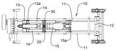
우선적으로 PLS트럭(1)은 차체를 이루는 한 쌍의 마주하는 샤시프레임(2)이 구비되고, 이러한 샤시프레임(2)의 상단에는 PLS조립체(10)가 일체로 고정 설치되며, 상기 PLS조립체(10)를 구성하는 한 쌍의 후크 암 실린더(14) 및 후크 암(15)은 메인프레임(11)의 상부로 돌출되지 않는 설치각도로 유지함으로써 전체적인 적재높이를 낮추어 PLS트럭(1)의 주행 안전성을 도모하면서도 특히 다단 언로딩 실린더(20)를 적용하여 낮은 설치각도로 인한 후크 암 실린더(14)의 초기 작동부하의 문제점을 적극적으로 해소함을 지배적인 특징으로 한다.First, the PLS truck (1) is equipped with a pair of facing chassis frames (2) that form the body, and the PLS assembly (10) is integrally and fixedly installed on the top of the chassis frame (2), and the PLS assembly ( The pair of hook arm cylinders (14) and hook arms (15) constituting 10) are maintained at an installation angle that does not protrude from the top of the main frame (11), thereby lowering the overall loading height and ensuring the driving safety of the PLS truck (1). The dominant feature is that the problem of the initial operating load of the
이를 위한 PLS조립체(10)는 한 쌍의 마주하는 메인프레임(11)의 후단에 리어프레임(12)이 일체로 연결되고, 전방에는 후크 암 실린더(14)를 연결 설치하기 위한 프론트프레임(13)이 연결되며, 상기 한 쌍의 메인프레임(11)의 사이에는 한 쌍의 후크 암 실린더(14)가 설치되고, 이러한 후크 암 실린더(14)의 작동에 따라 상하로 회전하는 후크 암(15)과 후크 암 실린더(14)는 도 3 및 도 7과 같이 상기 메인프레임(11)보다 상부로 돌출되지 않는 각도를 유지하도록 설치된다.The PLS assembly (10) for this purpose has a rear frame (12) integrally connected to the rear end of a pair of facing main frames (11), and a front frame (13) for connecting and installing the hook arm cylinder (14) at the front. is connected, and a pair of
즉 상기 한 쌍의 후크 암 실린더(14)의 일측은 한 쌍의 메인프레임(11)의 내면 측 프론트프레임(13)에 각각 설치된 실린더 브라켓(13a)에 피봇핀(14a)으로 관통하여 회전 가능하게 결합되고, 한 쌍의 후크 암 실린더(14)의 타측은 후크 암(15)의 양측에 피봇핀(14b)으로 관통하여 회전 자유롭게 결합되며, 상기 후크 암(15)은 메인프레임(11)의 사이에 회전축(15a)으로 관통하여 회전 가능하게 결합되는 한편, 상기 피봇핀(14a)(14b)이 설치된 피봇 포인트는 메인프레임(11)의 사이에 위치함으로써 후크 암(2)과 후크 암 실린더(14)는 상기 메인프레임(11)보다 상부로 돌출되지 않는 낮은 각도로 유지할 수 있게 된다.That is, one side of the pair of
따라서 적재높이를 낮추어 차량의 주행 안전성을 도모하고, 전체적인 구조를 간소화함은 물론 부피를 줄여 경량화를 구현하는 효과를 제공한다.Therefore, by lowering the loading height, the driving safety of the vehicle is improved, the overall structure is simplified, and the volume is reduced to achieve weight reduction.
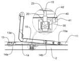
상기 후크 암(15)의 중간지점 하측에는 PLS트럭(1)의 샤시프레임(2) 사이에 실린더 하우징(30)이 연결 설치되고, 실린더 하우징(30)의 상부에는 다단 언로딩 실린더(20)가 설치되며, 이러한 다단 언로딩 실린더(20)는 후크 암 실린더(14)가 낮은 설치각도로 설치됨에 따라 후크 암 실린더(14)의 초기 작동부하가 발생하여 원활한 작동을 저해하던 문제점을 해소하기 위한 본 발명의 핵심기술이다.A
이러한 다단 언로딩 실린더(20)는 상기 후크 암 실린더(14)가 신장하여 초기 구동할 때 도 8과 같이 후크 암(15)을 상부로 들어올리는 과정과 연동하여 신장함으로써 후크 암(15)을 상승시켜 낮은 설치각도에 따른 초기 작동 부하를 경감하여 원활한 작동을 부여하고, 상기 후크 암(15)이 하향 회전할 때에는 후크 암(15)에 눌리면서 자중에 의해 자동으로 축소되어 원위치로 복귀될 수 있게 된다.This multi-stage unloading
따라서 상기 다단 언로딩 실린더(20)는 후크 암 실린더(14)의 초기 구동과 연동하여 신장함으로써 후크 암 실린더(14)의 초기 작동부하를 경감하여 원활한 작동성을 제고하고, 축소시에는 후크 암 실린더(14)의 하중을 완충하는 완충 스토퍼의 역할을 함으로써 충격 완화 및 내구성을 향상하는 특별한 효과를 제공한다.Therefore, the multi-stage unloading
한편, 본 발명은 상기 다단 언로딩 실린더(20)가 후크 암(15)을 승강시킬 때 후방으로 회전하면서 후크 암(15)을 직교상태에서 받쳐주어 상승력을 극대화할 수 있도록 하는 기술이 유기적으로 접목된다.Meanwhile, the present invention organically combines a technology that maximizes the lifting force by supporting the
이를 위한 기술구성으로 상기 실린더 하우징(30)은 도 4 내지 도 6과 같이 중앙 바닥면에 실린더 통공(31)이 형성되고, 실린더 통공(31)의 양측 상단에는 각각 하부 지지블럭(32)이 일체로 부착되며, 상기 다단 언로딩 실린더(20)는 외주면에 돌출 형성된 플랜지(21)의 양측에 돌출 형성된 회전축(22)이 하부 지지블럭(32) 및 상부 지지블럭(34)의 사이에 회전 가능하게 설치되고, 상기 하부 지지블럭(32) 및 상부 지지블럭(34)은 체결볼트(34)로 관통하여 일체로 체결된다.As a technical configuration for this, the
따라서 상기 다단 언로딩 실린더(20)는 회전 자유로운 상태를 유지함으로써 상기 후크 암(15)을 상승시킬 때 도 9와 같이 후방으로 회전하면서 최상부의 실린더(23)는 후크 암(15)에 직교상태로 접하도록 받쳐주어 접지면적을 확대하면서 상승력을 극대화하여 더욱 원활하게 후크 암(15)을 상승시키는 특별한 효과를 제공한다.Therefore, the multi-stage unloading
여기에서 상기 다단 언로딩 실린더(20)의 과도한 회전을 제한함과 아울러 회전각을 조절할 수 있도록 하는 기술이 추가로 접목된다.Here, technology is additionally incorporated to limit excessive rotation of the multi-stage unloading
이를 위한 기술구성으로 상기 실린더 하우징(30)은 도 10과 같이 전, 후면판(35)(36)의 상측 내면에 각각 스토퍼(37)가 부착되고, 상기 전, 후면판(35)(36)의 양측 및 스토퍼(37)를 관통하여 회전각 제어볼트(38)가 나사결합된다.As a technical configuration for this, the
따라서 상기 회전각 제어볼트(38)의 회전조작에 따라 회전각 제어볼트(38)를 전후로 위치 이동하면서 다단 언로딩 실린더(20)와의 거리를 조절함으로써 회전각을 자유롭게 조절할 수 있을 뿐만 아니라 다단 언로딩 실린더(20)의 과도한 회전을 방지하여 더욱 확실하게 초기 작동 부하를 해소하는 효과를 제공한다.Therefore, not only can the rotation angle be freely adjusted by adjusting the distance to the multi-stage unloading
또한, 본 발명은 후크 암(15)의 초기 상승시엔 후크 암 실린더(14)의 유압오일을 빠르게 회수하여 후크 암 실린더(14)가 더욱 신속하게 신장될 수 있도록 하고, 후크 암(15)의 하강시에는 유압오일이 후크 암 실린더(14)로 과도하게 공급하지 않도록 과압을 방지하기 위한 기술이 접목된다.In addition, the present invention quickly recovers the hydraulic oil of the
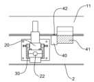
이를 위한 기술구성으로 상기 실린더 하우징(30)의 후방에는 한 쌍의 메인프레임(11)의 사이에 밸브 지지대(41)가 연결 설치되고, 상기 밸브 지지대(41)의 전면에 바이패스밸브(40)가 설치되며, 이러한 바이패스밸브(40)는 평상시 후크 암(15)에 의해 스위치(42)가 눌리면서 개방된 상태를 유지한다.As a technical configuration for this, a
따라서 상기 후크 암(15)의 상승 초기시 후크 암 실린더(14)의 유압오일은 기본적으로 리턴라인(53)을 통해 유압탱크(50)로 회수됨과 아울러 일부의 유압오일은 개방된 바이패스밸브(40)를 거쳐 다른 경로를 통해 유압탱크(50)로 빠르게 복귀함으로써 후크 암(15)이 더욱 신속하게 상승할 수 있도록 유도하여 초기 작동부하를 더욱 경감하는 효과를 제공한다.Therefore, at the beginning of the rise of the
그리고 상기 후크 암(15)의 상승으로 스위치(42)의 눌림이 해제되어 바이패스밸브(40)는 닫히게 되고, 이와 같이 닫힌 상태를 유지하는 바이패스밸브(40)는 후크 암(15)이 완전하게 하강하면 스위치(42)가 눌리면서 원상태로 개방되며, 상기 후크 암 실린더(14)로 계속 공급되는 유압오일은 개방된 바이패스밸브(40)를 거쳐 유압탱크(50)로 원활하게 회수됨으로써 후크 암 실린더(14)의 과압을 방지하는 효과를 제공한다.And, as the
한편, 본 발명의 후크 암 실린더(14), 다단 언로딩 실린더(20) 및 바이패스밸브(40)를 유기적으로 원활하게 작동하기 위한 유압회로도에 대해 상세하게 살펴보기로 한다.Meanwhile, we will look in detail at the hydraulic circuit diagram for organically and smoothly operating the
이와 같은 본 발명은 도 11과 같이 상기 유압탱크(50)와 연결된 유압펌프(51)는 수동 컨트롤러(52)와 연결되고, 수동 컨트롤러(52)는 리턴라인(53)과 연결되며, 수동 컨트롤러(52)의 일측에 연결된 제1 분기라인(54)은 한 쌍의 후크 암 실린더(14)의 사이에 연결된 공동 회수라인(55)과 연결됨과 아울러 일측에 연결된 다른 하나의 제2 분기라인(56)은 한 쌍의 후크 암 실린더(14)의 사이에 연결된 공동 공급라인(57)과 연결됨으로써 상기 수동 컨트롤러(52)를 조작하여 제1 분기라인(54)을 통해 한 쌍의 후크 암 실린더(14)에 유압오일을 공급하여 신장시킴과 아울러 제2 분기라인(56) 및 수동 컨트롤러(52)를 경유하여 리턴라인(53)을 통해 유압오일을 리턴 회수할 수 있게 된다.In this invention, as shown in Figure 11, the
그리고 상기 제1 분기라인(54) 및 제2 분기라인(56)에는 각각 유압오일의 흐름을 완전하게 차단하거나 유지할 수 있는 블록밸브(58)(58a)가 각각 설치된다.In addition,
또한, 상기 제2 분기라인(56)에서 분기된 언로딩라인(25)은 다단 언로딩 실린더(20)와 연결됨으로써 상기 한 쌍의 후크 암 실린더(14)를 신장시키는 과정과 연동하여 동시에 다단 언로딩 실린더(20)를 신장시킬 수 있으며, 상기 제1 분기라인(54)과 유압탱크(50)의 사이에 연결된 바이패스라인(15)에는 바이패스밸브(40)가 설치됨으로써 바이패스밸브(40)의 개방시 유압오일은 바이패스라인(15)을 통해 유압탱크(50)로 원활하게 회수될 수 있게 된다.In addition, the
1: PLS트럭 2: 샤시프레임
10: PLS조립체 11: 메인프레임
13: 프론트프레임 14: 후크 암 실린더
14a, 14b: 피봇핀 15: 후크 암
15a, 22: 회전축 20: 다단 언로딩 실린더
21: 플랜지 25: 언로딩라인
30: 실린더 하우징 31: 실린더 통공
32: 하부 지지블럭 33: 상부 지지블럭
34: 체결볼트 37: 스토퍼
38: 회전각 제어볼트 40: 바이패스밸브
41: 밸브 지지대 42: 스위치
45: 바이패스라인 50: 유압탱크
51: 유압펌프 52: 수동 컨트롤러
53: 리턴라인 54: 제1 분기라인
55: 공동 회수라인 56: 제2 분기라인
57: 공동 공급라인 58, 58a: 블록밸브1: PLS truck 2: Chassis frame
10: PLS assembly 11: main frame
13: Front frame 14: Hook arm cylinder
14a, 14b: pivot pin 15: hook arm
15a, 22: Rotating shaft 20: Multi-stage unloading cylinder
21: Flange 25: Unloading line
30: cylinder housing 31: cylinder hole
32: lower support block 33: upper support block
34: fastening bolt 37: stopper
38: Rotation angle control bolt 40: Bypass valve
41: valve support 42: switch
45: bypass line 50: hydraulic tank
51: Hydraulic pump 52: Manual controller
53: return line 54: first branch line
55: common recovery line 56: second branch line
57:
Claims (6)
Translated fromKorean상기 한 쌍의 샤시프레임(2)의 사이에 연결 설치된 실린더 하우징(30)에 설치되고, 상기 후크 암 실린더(14)의 초기 구동과 연동하여 후크 암(15)을 상승시켜 낮은 설치각도에 따른 초기 작동 부하를 경감하며, 상기 후크 암(15)의 하향 회전시 자중에 의해 수축되면서 원위치로 복귀되는 다단 언로딩 실린더(20)로 이루어지는 한편;
상기 실린더 하우징(30)은 중앙 바닥면에 형성된 실린더 통공(31)의 양측 상단에 하부 지지블럭(32)이 일체로 부착되고, 상기 다단 언로딩 실린더(20)는 양측에 형성된 회전축(22)이 하부 지지블럭(32) 및 상부 지지블럭(34)의 사이에 회전 가능하게 설치되어 상기 후크 암(15)을 상승시킬 때 최상부의 실린더(23)가 후크 암(15)에 직교상태로 접하는 것을 특징으로 하는 후크 암에 다단 언로딩 실린더가 적용된 PLS트럭 시스템.
It is fixedly installed on the top of the chassis frame (2) of the PLS truck (1), and the rear frame (12) is connected to the rear end of a pair of facing main frames (11), and is located between the pair of main frames (11). A pair of hook arm cylinders 14 installed on the and a hook arm 2 that rotates up and down according to the operation of the hook arm cylinder 14 are installed to maintain an angle that does not protrude above the main frame 11. A PLS assembly (10) comprising;
It is installed in the cylinder housing 30 connected and installed between the pair of chassis frames 2, and raises the hook arm 15 in conjunction with the initial operation of the hook arm cylinder 14 to achieve an initial starting angle according to a low installation angle. It reduces the operating load and consists of a multi-stage unloading cylinder (20) that is contracted by its own weight when the hook arm (15) rotates downward and returns to its original position;
The cylinder housing 30 has lower support blocks 32 integrally attached to the upper ends of both sides of the cylinder hole 31 formed on the center bottom, and the multi-stage unloading cylinder 20 has rotation axes 22 formed on both sides. It is rotatably installed between the lower support block 32 and the upper support block 34, and when the hook arm 15 is raised, the uppermost cylinder 23 contacts the hook arm 15 at right angles. A PLS truck system with a multi-stage unloading cylinder applied to the hook arm.
상기 한 쌍의 후크 암 실린더(14)의 일측은 메인프레임(11)의 내면에 각각 설치된 실린더 브라켓(13a)에 피봇핀(14a)으로 관통하여 결합되고, 타측은 한 쌍의 메인프레임(11)의 사이에 회전 가능하게 설치된 후크 암(15)의 양측에 피봇핀(14b)으로 관통하여 결합되며, 상기 피봇핀(14a)(14b)이 설치된 피봇포인트는 메인프레임(11)의 사이에 위치하는 것을 특징으로 하는 후크 암에 다단 언로딩 실린더가 적용된 PLS트럭 시스템.
According to clause 1,
One side of the pair of hook arm cylinders 14 is coupled to the cylinder bracket 13a installed on the inner surface of the main frame 11 with a pivot pin 14a, and the other side is connected to the pair of main frames 11. It is coupled through a pivot pin (14b) on both sides of the hook arm (15) rotatably installed between them, and the pivot point where the pivot pins (14a) (14b) are installed is located between the main frame (11). A PLS truck system with a multi-stage unloading cylinder applied to the hook arm.
상기 실린더 하우징(30)의 전, 후면판(35)(36) 상측 내면에는 각각 스토퍼(37)가 부착되고, 상기 전, 후면판(35)(36)의 양측 및 스토퍼(37)를 관통하여 나사결합된 회전각 제어볼트(38)는 다단 언로딩 실린더(20)의 회전각을 조절하는 것을 특징으로 하는 후크 암에 다단 언로딩 실린더가 적용된 PLS트럭 시스템.
According to clause 1,
Stoppers 37 are attached to the upper inner surfaces of the front and rear plates 35 and 36 of the cylinder housing 30, respectively, and penetrate through both sides of the front and rear plates 35 and 36 and the stoppers 37. A PLS truck system with a multi-stage unloading cylinder applied to a hook arm, wherein the screwed rotation angle control bolt (38) controls the rotation angle of the multi-stage unloading cylinder (20).
상기 한 쌍의 샤시프레임(2)의 사이에 연결 설치된 실린더 하우징(30)에 설치되고, 상기 후크 암 실린더(14)의 초기 구동과 연동하여 후크 암(15)을 상승시켜 낮은 설치각도에 따른 초기 작동 부하를 경감하며, 상기 후크 암(15)의 하향 회전시 자중에 의해 수축되면서 원위치로 복귀되는 다단 언로딩 실린더(20)로 이루어지는 한편;
상기 실린더 하우징(30)의 후방에는 한 쌍의 메인프레임(11)의 사이에 밸브 지지대(41)가 연결 설치되고, 상기 밸브 지지대(41)의 전면에 설치된 바이패스밸브(40)는 평상시 후크 암(15)에 의해 스위치(42)가 눌리면서 개방된 상태를 유지하며, 상기 후크 암(15)의 상승 초기시 후크 암 실린더(14)의 유압오일은 개방된 바이패스밸브(40)를 거쳐 유압탱크(50)로 빠르게 복귀하면서 후크 암(15)의 신속한 상승을 유도하는 한편;
상기 후크 암(15)의 상승으로 닫힌 상태를 유지하는 바이패스밸브(40)는 후크 암(15)이 완전하게 하강하면 스위치(42)가 눌리면서 개방되고, 상기 후크 암 실린더(14)로 계속 공급되는 유압오일은 개방된 바이패스밸브(40)를 거쳐 유압탱크(50)로 회수되어 후크 암 실린더(14)의 과압을 방지하는 것을 특징으로 하는 후크 암에 다단 언로딩 실린더가 적용된 PLS트럭 시스템.
It is fixedly installed on the top of the chassis frame (2) of the PLS truck (1), and the rear frame (12) is connected to the rear end of a pair of facing main frames (11), and is located between the pair of main frames (11). A pair of hook arm cylinders 14 installed on the and a hook arm 2 that rotates up and down according to the operation of the hook arm cylinder 14 are installed to maintain an angle that does not protrude above the main frame 11. A PLS assembly (10) comprising;
It is installed in the cylinder housing 30 connected and installed between the pair of chassis frames 2, and raises the hook arm 15 in conjunction with the initial operation of the hook arm cylinder 14 to achieve an initial starting angle according to a low installation angle. It reduces the operating load and consists of a multi-stage unloading cylinder (20) that is contracted by its own weight when the hook arm (15) rotates downward and returns to its original position;
At the rear of the cylinder housing 30, a valve support 41 is connected and installed between a pair of main frames 11, and the bypass valve 40 installed on the front of the valve support 41 is normally connected to the hook arm. The switch 42 is pressed by (15) and remains open, and at the beginning of the rise of the hook arm 15, the hydraulic oil of the hook arm cylinder 14 flows into the hydraulic tank through the opened bypass valve 40. A quick return to (50) induces a rapid rise of the hook arm (15);
The bypass valve 40, which remains closed as the hook arm 15 rises, is opened by pressing the switch 42 when the hook arm 15 is completely lowered, and continues to supply to the hook arm cylinder 14. The hydraulic oil is returned to the hydraulic tank 50 through the open bypass valve 40 to prevent overpressure of the hook arm cylinder 14. A PLS truck system with a multi-stage unloading cylinder applied to the hook arm.
상기 유압탱크(50)와 연결된 유압펌프(51)는 수동 컨트롤러(52)와 연결되고, 수동 컨트롤러(52)는 유압탱크(50)와 리턴라인(53)으로 연결되며, 수동 컨트롤러(52)의 일측에 연결된 제1 분기라인(54)은 한 쌍의 후크 암 실린더(14)의 사이에 연결된 공동 회수라인(55)과 연결됨과 아울러 수동 컨트롤러(52)의 일측에 연결된 다른 제2 분기라인(56)은 한 쌍의 후크 암 실린더(14)의 사이에 연결된 공동 공급라인(57)과 연결되는 한편, 상기 제2 분기라인(56)에서 분기된 언로딩라인(25)은 다단 언로딩 실린더(20)와 연결되고, 상기 제1 분기라인(54)과 유압탱크(50)의 사이에 연결된 바이패스라인(15)에는 바이패스밸브(40)가 설치된 것을 특징으로하는 후크 암에 다단 언로딩 실린더가 적용된 PLS트럭 시스템.According to clause 5,
The hydraulic pump 51 connected to the hydraulic tank 50 is connected to the manual controller 52, and the manual controller 52 is connected to the hydraulic tank 50 and the return line 53, and the manual controller 52 The first branch line 54 connected to one side is connected to a common recovery line 55 connected between a pair of hook arm cylinders 14, and the other second branch line 56 connected to one side of the manual controller 52 ) is connected to a common supply line 57 connected between a pair of hook arm cylinders 14, while the unloading line 25 branched from the second branch line 56 is connected to the multi-stage unloading cylinder 20 ), and a multi-stage unloading cylinder is installed on the hook arm, wherein a bypass valve 40 is installed in the bypass line 15 connected between the first branch line 54 and the hydraulic tank 50. Applied PLS truck system.
Priority Applications (1)
| Application Number | Priority Date | Filing Date | Title |
|---|---|---|---|
| KR1020230061488AKR102576976B1 (en) | 2023-05-12 | 2023-05-12 | PLS truck system with multi-stage unloading cylinder applied to the hook arm |
Applications Claiming Priority (1)
| Application Number | Priority Date | Filing Date | Title |
|---|---|---|---|
| KR1020230061488AKR102576976B1 (en) | 2023-05-12 | 2023-05-12 | PLS truck system with multi-stage unloading cylinder applied to the hook arm |
Publications (1)
| Publication Number | Publication Date |
|---|---|
| KR102576976B1true KR102576976B1 (en) | 2023-09-12 |
Family
ID=88019654
Family Applications (1)
| Application Number | Title | Priority Date | Filing Date |
|---|---|---|---|
| KR1020230061488AActiveKR102576976B1 (en) | 2023-05-12 | 2023-05-12 | PLS truck system with multi-stage unloading cylinder applied to the hook arm |
Country Status (1)
| Country | Link |
|---|---|
| KR (1) | KR102576976B1 (en) |
Citations (2)
| Publication number | Priority date | Publication date | Assignee | Title |
|---|---|---|---|---|
| JP2007331677A (en)* | 2006-06-19 | 2007-12-27 | Hanamidai Jidosha:Kk | Deck tilting device and deck tilting method for vehicle |
| KR102529417B1 (en)* | 2023-01-09 | 2023-05-09 | 리텍 주식회사 | Korean Mobility Platform PLS Truck System |
- 2023
- 2023-05-12KRKR1020230061488Apatent/KR102576976B1/enactiveActive
Patent Citations (2)
| Publication number | Priority date | Publication date | Assignee | Title |
|---|---|---|---|---|
| JP2007331677A (en)* | 2006-06-19 | 2007-12-27 | Hanamidai Jidosha:Kk | Deck tilting device and deck tilting method for vehicle |
| KR102529417B1 (en)* | 2023-01-09 | 2023-05-09 | 리텍 주식회사 | Korean Mobility Platform PLS Truck System |
Similar Documents
| Publication | Publication Date | Title |
|---|---|---|
| US20130036673A1 (en) | Container or vehicle body with side door and a side door drive unit | |
| US6196634B1 (en) | Dumping bed liner for pickup truck | |
| US4126357A (en) | Demountable tilting container assemblies for light vans and trucks | |
| CN1155505C (en) | Container loading and unloading device and container handling equipment comprising same | |
| ZA200006132B (en) | Transportable lift truck with telescopic lifting arm. | |
| US6799935B1 (en) | Lifting apparatus for user in the bed of a pickup truck | |
| US8052221B2 (en) | Tractor | |
| CN205768886U (en) | Bidirectional turning dumper | |
| CN111792579A (en) | Anti-tilting method of forklift based on goods tilting prevention | |
| US9266670B2 (en) | Lifting device for a container | |
| US3217912A (en) | Container handling fork lift mechanism | |
| KR102576976B1 (en) | PLS truck system with multi-stage unloading cylinder applied to the hook arm | |
| JP5237068B2 (en) | Loading platform lifting unit and its transport method | |
| RU2638340C2 (en) | Method of adjustment and operation of loading platform and device for implementation of this method | |
| US6561589B2 (en) | Dual acting truck hoist | |
| KR102044089B1 (en) | Dump body module for general truck mounting | |
| KR101313077B1 (en) | Storage lift gate | |
| US11590876B2 (en) | Truck load bed with hydraulic tilt/hydraulic tail that utilizes a unified hinge | |
| CN1754821A (en) | Forklift | |
| US20050058528A1 (en) | Elevator delivery system for use in truck body or trailer | |
| CN215108263U (en) | Automatic chamber door of trailer and contain trailer of this chamber door | |
| KR102468543B1 (en) | Forklift for moving small and medium cargo | |
| US10005381B2 (en) | Side-loading liftgate having integrated stabilizer leg | |
| KR101313076B1 (en) | Storage lift gate | |
| CN218805429U (en) | Installation mechanism of side-tipping type dumper carriage |
Legal Events
| Date | Code | Title | Description |
|---|---|---|---|
| PA0109 | Patent application | Patent event code:PA01091R01D Comment text:Patent Application Patent event date:20230512 | |
| PA0201 | Request for examination | ||
| PA0302 | Request for accelerated examination | Patent event date:20230512 Patent event code:PA03022R01D Comment text:Request for Accelerated Examination | |
| PE0902 | Notice of grounds for rejection | Comment text:Notification of reason for refusal Patent event date:20230703 Patent event code:PE09021S01D | |
| E701 | Decision to grant or registration of patent right | ||
| PE0701 | Decision of registration | Patent event code:PE07011S01D Comment text:Decision to Grant Registration Patent event date:20230905 | |
| GRNT | Written decision to grant | ||
| PR0701 | Registration of establishment | Comment text:Registration of Establishment Patent event date:20230906 Patent event code:PR07011E01D | |
| PR1002 | Payment of registration fee | Payment date:20230906 End annual number:3 Start annual number:1 | |
| PG1601 | Publication of registration |