KR102572439B1 - Epitaxial growth apparatus and multi-layer gas supply module used therefor - Google Patents
Epitaxial growth apparatus and multi-layer gas supply module used thereforDownload PDFInfo
- Publication number
- KR102572439B1 KR102572439B1KR1020220167459AKR20220167459AKR102572439B1KR 102572439 B1KR102572439 B1KR 102572439B1KR 1020220167459 AKR1020220167459 AKR 1020220167459AKR 20220167459 AKR20220167459 AKR 20220167459AKR 102572439 B1KR102572439 B1KR 102572439B1
- Authority
- KR
- South Korea
- Prior art keywords
- layer
- ports
- gas
- holes
- port
- Prior art date
- Legal status (The legal status is an assumption and is not a legal conclusion. Google has not performed a legal analysis and makes no representation as to the accuracy of the status listed.)
- Active
Links
Images


Classifications
- C—CHEMISTRY; METALLURGY
- C30—CRYSTAL GROWTH
- C30B—SINGLE-CRYSTAL GROWTH; UNIDIRECTIONAL SOLIDIFICATION OF EUTECTIC MATERIAL OR UNIDIRECTIONAL DEMIXING OF EUTECTOID MATERIAL; REFINING BY ZONE-MELTING OF MATERIAL; PRODUCTION OF A HOMOGENEOUS POLYCRYSTALLINE MATERIAL WITH DEFINED STRUCTURE; SINGLE CRYSTALS OR HOMOGENEOUS POLYCRYSTALLINE MATERIAL WITH DEFINED STRUCTURE; AFTER-TREATMENT OF SINGLE CRYSTALS OR A HOMOGENEOUS POLYCRYSTALLINE MATERIAL WITH DEFINED STRUCTURE; APPARATUS THEREFOR
- C30B25/00—Single-crystal growth by chemical reaction of reactive gases, e.g. chemical vapour-deposition growth
- C30B25/02—Epitaxial-layer growth
- C30B25/14—Feed and outlet means for the gases; Modifying the flow of the reactive gases
- C—CHEMISTRY; METALLURGY
- C23—COATING METALLIC MATERIAL; COATING MATERIAL WITH METALLIC MATERIAL; CHEMICAL SURFACE TREATMENT; DIFFUSION TREATMENT OF METALLIC MATERIAL; COATING BY VACUUM EVAPORATION, BY SPUTTERING, BY ION IMPLANTATION OR BY CHEMICAL VAPOUR DEPOSITION, IN GENERAL; INHIBITING CORROSION OF METALLIC MATERIAL OR INCRUSTATION IN GENERAL
- C23C—COATING METALLIC MATERIAL; COATING MATERIAL WITH METALLIC MATERIAL; SURFACE TREATMENT OF METALLIC MATERIAL BY DIFFUSION INTO THE SURFACE, BY CHEMICAL CONVERSION OR SUBSTITUTION; COATING BY VACUUM EVAPORATION, BY SPUTTERING, BY ION IMPLANTATION OR BY CHEMICAL VAPOUR DEPOSITION, IN GENERAL
- C23C16/00—Chemical coating by decomposition of gaseous compounds, without leaving reaction products of surface material in the coating, i.e. chemical vapour deposition [CVD] processes
- C23C16/22—Chemical coating by decomposition of gaseous compounds, without leaving reaction products of surface material in the coating, i.e. chemical vapour deposition [CVD] processes characterised by the deposition of inorganic material, other than metallic material
- C23C16/30—Deposition of compounds, mixtures or solid solutions, e.g. borides, carbides, nitrides
- C23C16/32—Carbides
- C23C16/325—Silicon carbide
- C—CHEMISTRY; METALLURGY
- C23—COATING METALLIC MATERIAL; COATING MATERIAL WITH METALLIC MATERIAL; CHEMICAL SURFACE TREATMENT; DIFFUSION TREATMENT OF METALLIC MATERIAL; COATING BY VACUUM EVAPORATION, BY SPUTTERING, BY ION IMPLANTATION OR BY CHEMICAL VAPOUR DEPOSITION, IN GENERAL; INHIBITING CORROSION OF METALLIC MATERIAL OR INCRUSTATION IN GENERAL
- C23C—COATING METALLIC MATERIAL; COATING MATERIAL WITH METALLIC MATERIAL; SURFACE TREATMENT OF METALLIC MATERIAL BY DIFFUSION INTO THE SURFACE, BY CHEMICAL CONVERSION OR SUBSTITUTION; COATING BY VACUUM EVAPORATION, BY SPUTTERING, BY ION IMPLANTATION OR BY CHEMICAL VAPOUR DEPOSITION, IN GENERAL
- C23C16/00—Chemical coating by decomposition of gaseous compounds, without leaving reaction products of surface material in the coating, i.e. chemical vapour deposition [CVD] processes
- C23C16/44—Chemical coating by decomposition of gaseous compounds, without leaving reaction products of surface material in the coating, i.e. chemical vapour deposition [CVD] processes characterised by the method of coating
- C23C16/455—Chemical coating by decomposition of gaseous compounds, without leaving reaction products of surface material in the coating, i.e. chemical vapour deposition [CVD] processes characterised by the method of coating characterised by the method used for introducing gases into reaction chamber or for modifying gas flows in reaction chamber
- C23C16/45519—Inert gas curtains
- C—CHEMISTRY; METALLURGY
- C23—COATING METALLIC MATERIAL; COATING MATERIAL WITH METALLIC MATERIAL; CHEMICAL SURFACE TREATMENT; DIFFUSION TREATMENT OF METALLIC MATERIAL; COATING BY VACUUM EVAPORATION, BY SPUTTERING, BY ION IMPLANTATION OR BY CHEMICAL VAPOUR DEPOSITION, IN GENERAL; INHIBITING CORROSION OF METALLIC MATERIAL OR INCRUSTATION IN GENERAL
- C23C—COATING METALLIC MATERIAL; COATING MATERIAL WITH METALLIC MATERIAL; SURFACE TREATMENT OF METALLIC MATERIAL BY DIFFUSION INTO THE SURFACE, BY CHEMICAL CONVERSION OR SUBSTITUTION; COATING BY VACUUM EVAPORATION, BY SPUTTERING, BY ION IMPLANTATION OR BY CHEMICAL VAPOUR DEPOSITION, IN GENERAL
- C23C16/00—Chemical coating by decomposition of gaseous compounds, without leaving reaction products of surface material in the coating, i.e. chemical vapour deposition [CVD] processes
- C23C16/44—Chemical coating by decomposition of gaseous compounds, without leaving reaction products of surface material in the coating, i.e. chemical vapour deposition [CVD] processes characterised by the method of coating
- C23C16/455—Chemical coating by decomposition of gaseous compounds, without leaving reaction products of surface material in the coating, i.e. chemical vapour deposition [CVD] processes characterised by the method of coating characterised by the method used for introducing gases into reaction chamber or for modifying gas flows in reaction chamber
- C23C16/45563—Gas nozzles
- C23C16/45574—Nozzles for more than one gas
- C—CHEMISTRY; METALLURGY
- C23—COATING METALLIC MATERIAL; COATING MATERIAL WITH METALLIC MATERIAL; CHEMICAL SURFACE TREATMENT; DIFFUSION TREATMENT OF METALLIC MATERIAL; COATING BY VACUUM EVAPORATION, BY SPUTTERING, BY ION IMPLANTATION OR BY CHEMICAL VAPOUR DEPOSITION, IN GENERAL; INHIBITING CORROSION OF METALLIC MATERIAL OR INCRUSTATION IN GENERAL
- C23C—COATING METALLIC MATERIAL; COATING MATERIAL WITH METALLIC MATERIAL; SURFACE TREATMENT OF METALLIC MATERIAL BY DIFFUSION INTO THE SURFACE, BY CHEMICAL CONVERSION OR SUBSTITUTION; COATING BY VACUUM EVAPORATION, BY SPUTTERING, BY ION IMPLANTATION OR BY CHEMICAL VAPOUR DEPOSITION, IN GENERAL
- C23C16/00—Chemical coating by decomposition of gaseous compounds, without leaving reaction products of surface material in the coating, i.e. chemical vapour deposition [CVD] processes
- C23C16/44—Chemical coating by decomposition of gaseous compounds, without leaving reaction products of surface material in the coating, i.e. chemical vapour deposition [CVD] processes characterised by the method of coating
- C23C16/455—Chemical coating by decomposition of gaseous compounds, without leaving reaction products of surface material in the coating, i.e. chemical vapour deposition [CVD] processes characterised by the method of coating characterised by the method used for introducing gases into reaction chamber or for modifying gas flows in reaction chamber
- C23C16/45563—Gas nozzles
- C23C16/45578—Elongated nozzles, tubes with holes
- C—CHEMISTRY; METALLURGY
- C23—COATING METALLIC MATERIAL; COATING MATERIAL WITH METALLIC MATERIAL; CHEMICAL SURFACE TREATMENT; DIFFUSION TREATMENT OF METALLIC MATERIAL; COATING BY VACUUM EVAPORATION, BY SPUTTERING, BY ION IMPLANTATION OR BY CHEMICAL VAPOUR DEPOSITION, IN GENERAL; INHIBITING CORROSION OF METALLIC MATERIAL OR INCRUSTATION IN GENERAL
- C23C—COATING METALLIC MATERIAL; COATING MATERIAL WITH METALLIC MATERIAL; SURFACE TREATMENT OF METALLIC MATERIAL BY DIFFUSION INTO THE SURFACE, BY CHEMICAL CONVERSION OR SUBSTITUTION; COATING BY VACUUM EVAPORATION, BY SPUTTERING, BY ION IMPLANTATION OR BY CHEMICAL VAPOUR DEPOSITION, IN GENERAL
- C23C16/00—Chemical coating by decomposition of gaseous compounds, without leaving reaction products of surface material in the coating, i.e. chemical vapour deposition [CVD] processes
- C23C16/44—Chemical coating by decomposition of gaseous compounds, without leaving reaction products of surface material in the coating, i.e. chemical vapour deposition [CVD] processes characterised by the method of coating
- C23C16/458—Chemical coating by decomposition of gaseous compounds, without leaving reaction products of surface material in the coating, i.e. chemical vapour deposition [CVD] processes characterised by the method of coating characterised by the method used for supporting substrates in the reaction chamber
- C23C16/4582—Rigid and flat substrates, e.g. plates or discs
- C23C16/4583—Rigid and flat substrates, e.g. plates or discs the substrate being supported substantially horizontally
- C—CHEMISTRY; METALLURGY
- C30—CRYSTAL GROWTH
- C30B—SINGLE-CRYSTAL GROWTH; UNIDIRECTIONAL SOLIDIFICATION OF EUTECTIC MATERIAL OR UNIDIRECTIONAL DEMIXING OF EUTECTOID MATERIAL; REFINING BY ZONE-MELTING OF MATERIAL; PRODUCTION OF A HOMOGENEOUS POLYCRYSTALLINE MATERIAL WITH DEFINED STRUCTURE; SINGLE CRYSTALS OR HOMOGENEOUS POLYCRYSTALLINE MATERIAL WITH DEFINED STRUCTURE; AFTER-TREATMENT OF SINGLE CRYSTALS OR A HOMOGENEOUS POLYCRYSTALLINE MATERIAL WITH DEFINED STRUCTURE; APPARATUS THEREFOR
- C30B25/00—Single-crystal growth by chemical reaction of reactive gases, e.g. chemical vapour-deposition growth
- C30B25/02—Epitaxial-layer growth
- C30B25/12—Substrate holders or susceptors
- C—CHEMISTRY; METALLURGY
- C30—CRYSTAL GROWTH
- C30B—SINGLE-CRYSTAL GROWTH; UNIDIRECTIONAL SOLIDIFICATION OF EUTECTIC MATERIAL OR UNIDIRECTIONAL DEMIXING OF EUTECTOID MATERIAL; REFINING BY ZONE-MELTING OF MATERIAL; PRODUCTION OF A HOMOGENEOUS POLYCRYSTALLINE MATERIAL WITH DEFINED STRUCTURE; SINGLE CRYSTALS OR HOMOGENEOUS POLYCRYSTALLINE MATERIAL WITH DEFINED STRUCTURE; AFTER-TREATMENT OF SINGLE CRYSTALS OR A HOMOGENEOUS POLYCRYSTALLINE MATERIAL WITH DEFINED STRUCTURE; APPARATUS THEREFOR
- C30B25/00—Single-crystal growth by chemical reaction of reactive gases, e.g. chemical vapour-deposition growth
- C30B25/02—Epitaxial-layer growth
- C30B25/16—Controlling or regulating
- C—CHEMISTRY; METALLURGY
- C30—CRYSTAL GROWTH
- C30B—SINGLE-CRYSTAL GROWTH; UNIDIRECTIONAL SOLIDIFICATION OF EUTECTIC MATERIAL OR UNIDIRECTIONAL DEMIXING OF EUTECTOID MATERIAL; REFINING BY ZONE-MELTING OF MATERIAL; PRODUCTION OF A HOMOGENEOUS POLYCRYSTALLINE MATERIAL WITH DEFINED STRUCTURE; SINGLE CRYSTALS OR HOMOGENEOUS POLYCRYSTALLINE MATERIAL WITH DEFINED STRUCTURE; AFTER-TREATMENT OF SINGLE CRYSTALS OR A HOMOGENEOUS POLYCRYSTALLINE MATERIAL WITH DEFINED STRUCTURE; APPARATUS THEREFOR
- C30B29/00—Single crystals or homogeneous polycrystalline material with defined structure characterised by the material or by their shape
- C30B29/10—Inorganic compounds or compositions
- C30B29/36—Carbides
Landscapes
- Chemical & Material Sciences (AREA)
- Engineering & Computer Science (AREA)
- Materials Engineering (AREA)
- Metallurgy (AREA)
- Organic Chemistry (AREA)
- General Chemical & Material Sciences (AREA)
- Chemical Kinetics & Catalysis (AREA)
- Mechanical Engineering (AREA)
- Crystallography & Structural Chemistry (AREA)
- Inorganic Chemistry (AREA)
- Chemical Vapour Deposition (AREA)
Abstract
Description
Translated fromKorean본 발명은 웨이퍼에 대해 에피택셜 층을 성장시키는데 사용되는 에피택셜 성장장치와 그의 가스공급 모듈에 관한 것이다.The present invention relates to an epitaxial growth apparatus used for growing an epitaxial layer on a wafer and a gas supply module thereof.
일반적으로, 에피택셜 성장(Epitaxial growth)은 씨드(Seed) 웨이퍼를 밑에 깔고 격자 방향을 유지하면서 단결정으로 성장해 추가로 새로운 층을 쌓아 올리는 것이다. 에피택셜 성장을 위해서는 웨이퍼에 가스가 작용하게 하는 성장장치가 필요하다.In general, epitaxial growth is a process in which a seed wafer is placed underneath and a new layer is added by growing into a single crystal while maintaining the lattice direction. Epitaxial growth requires a growth device that allows gas to act on the wafer.
에피택셜 성장장치에 있어서, 가스 공급 계통은, 가스 탱크로부터 챔버 내로 가스가 주입되는 순서에 따라, 인젝터(Injector), 배플(Baffle), 인서트(Insert), 그리고 라이너(Liner)로 구성된다.In the epitaxial growth apparatus, the gas supply system is composed of an injector, a baffle, an insert, and a liner according to the order in which gas is injected into the chamber from the gas tank.
가스 공급에 있어서 가장 중요한 점은 챔버 내에 균일한 가스 분포를 형성하는 것이다. 이를 통해, 대면적 기판(8인치 이상의 크기를 갖는 기판)에서 균일한 에피택설 층의 두께를 구현할 수 있다. 이를 통해 성장된 에피택설 층의 균일도 1% 이하가 달성되는 것이 바람직하다.The most important point in gas supply is to form a uniform gas distribution in the chamber. Through this, it is possible to implement a uniform thickness of the epitaxial layer on a large-area substrate (a substrate having a size of 8 inches or more). Through this, it is desirable to achieve a uniformity of 1% or less of the grown epitaxial layer.
그러나, 종래의 가스 공급 계통은 복수의 가스가 단층 주입구를 통해 챔버에 주입되어 가스 분포의 균일도를 달성하기 어려웠다. 특히 대면적 기판에 대해서도 더욱 그러하다. 또한, 기판의 중심부와 가장 자리에서의 가스 분포가 균일하지 않다. 이로 인해 성장된 에피 층의 두께 불균일도가 5% 이상으로 나빠지는 결과를 보인다.However, in the conventional gas supply system, it is difficult to achieve uniformity of gas distribution because a plurality of gases are injected into the chamber through a single-layer inlet. This is especially true for large-area substrates. In addition, gas distribution at the center and edge of the substrate is not uniform. As a result, the thickness non-uniformity of the grown epitaxial layer deteriorates to 5% or more.
본 발명의 일 목적은, 대면적 기판에서 균일한 에피텍셜 층을 성장시키기 위해 기판 전체 영역에서 균일한 가스 분포를 형성할 수 있는, 에피택셜 성장장치 및 그에 사용되는 다층 가스공급 모듈을 제공하는 것이다.One object of the present invention is to provide an epitaxial growth apparatus and a multi-layer gas supply module used therefor, capable of forming a uniform gas distribution over the entire area of a substrate in order to grow a uniform epitaxial layer on a large-area substrate. .
상기한 과제를 실현하기 위한 본 발명의 일 측면에 따른 에피택셜 성장장치는, 반응 챔버; 상기 반응 챔버 내에 위치하고, 웨이퍼가 안착되는 서셉터; 및 상기 웨이퍼에 에피택셜 층을 형성하기 위해 상기 반응 챔버에 대해 가스를 공급하는 다층 가스공급 모듈을 포함하고, 상기 다층 가스공급 모듈은, 층별로 서로 다른 가스를 토출하는 복수 층의 포트들을 구비하고, 상기 복수 층의 포트들 중 각 층의 포트들은 상기 웨이퍼의 중앙 영역에 대응하는 센터 포트와 상기 웨이퍼의 양측 가장자리 영역에 대응하는 한 쌍의 엣지 포트를 구비하는, 인젝터; 및 상기 각 층의 포트들 중 상기 센터 포트와 상기 엣지 포트에 입력되는 가스 유량을 서로 독립적으로 배분하도록 구성되는 유량배분 유닛을 포함할 수 있다.Epitaxial growth apparatus according to an aspect of the present invention for realizing the above object, the reaction chamber; a susceptor located in the reaction chamber and on which a wafer is seated; and a multi-layer gas supply module supplying gas to the reaction chamber to form an epitaxial layer on the wafer, wherein the multi-layer gas supply module includes a plurality of layers of ports for discharging different gases for each layer; , wherein the ports of each layer among the ports of the plurality of layers include a center port corresponding to a central region of the wafer and a pair of edge ports corresponding to both side edge regions of the wafer, an injector; and a flow distribution unit configured to independently distribute gas flow rates input to the center port and the edge port among the ports of each layer.
여기서, 상기 각 층의 포트들은, 상기 센터 포트와 상기 한 쌍의 엣지 포트 사이에 각각 배치되는 한 쌍의 미들 포트를 더 포함할 수 있다.Here, the ports of each layer may further include a pair of middle ports respectively disposed between the center port and the pair of edge ports.
여기서, 상기 유량배분 유닛은, 상기 포트들 각각에 연결된 유량제어기(Mass Flow Controller)들을 포함할 수 있다.Here, the flow distribution unit may include mass flow controllers connected to each of the ports.
여기서, 상기 복수 층의 포트들은, 상기 에피택셜 층을 형성하는 원료 가스를 토출하는 제1 층의 포트들; 및 상기 제1 층의 포트들 보다 상측에 위치하고, 상기 원료 가스의 상방 확산을 차단하는 차단 가스를 토출하는 제2 층의 포트들을 포함할 수 있다.Here, the ports of the plurality of layers may include ports of the first layer for discharging source gas forming the epitaxial layer; and ports of a second layer located above the ports of the first layer and discharging a blocking gas blocking upward diffusion of the source gas.
여기서, 상기 복수 층의 포트들은, 상기 제1 층의 포트들의 하측에 배치되고, 상기 에피택셜 층의 성장시에 발생하는 부산물을 정화하는 정화 가스를 토출하는 제3 층의 포트들을 포함할 수 있다.Here, the ports of the plurality of layers may include ports of a third layer disposed below the ports of the first layer and discharging a cleaning gas for purifying by-products generated during the growth of the epitaxial layer. .
여기서, 상기 다층 가스공급 모듈은, 상기 인젝터의 전방에 위치하여, 상기 포트들에서 토출된 가스를 통과시키는 통과홀들을 구비하는 배플을 더 포함하고, 상기 통과홀들은, 상기 제1 층의 포트들에 대응하는 제1 층의 통과홀들; 상기 제2 층의 포트들에 대응하는 제2 층의 통과홀들; 및 상기 제3 층의 포트들에 대응하는 제3 층의 통과홀들을 포함하고, 상기 제2 층의 통과홀들은, 원통 형상을 갖고, 상기 제1 층의 통과홀들 및 상기 제3층의 통과홀들은, 원통 형상인 것과 콘 형상인 것이 섞여 있을 수 있다.Here, the multi-layer gas supply module further includes a baffle located in front of the injector and having passage holes through which gas discharged from the ports passes, the passage holes being the ports of the first layer. through-holes of the first layer corresponding to; passage holes of the second layer corresponding to the ports of the second layer; and passage holes of the third layer corresponding to the ports of the third layer, the passage holes of the second layer having a cylindrical shape, and the passage holes of the first layer and the passage holes of the third layer. The holes may be a mixture of cylindrical and cone shaped.
여기서, 상기 제1 층의 통과홀들 및 상기 제3층의 통과홀들 중 상기 센터 포트에 대응하는 통과홀들은 원통 형상을 갖고, 상기 제1 층의 통과홀들 및 상기 제3층의 통과홀들 중 상기 엣지 포트에 대응하는 통과홀들은 콘 형상을 갖고, 상기 제3 층의 통과홀들은, 상기 제1 층의 통과홀들에 비해 작은 단면 크기를 가질 수 있다.Here, among the through holes of the first layer and the through holes of the third layer, the through holes corresponding to the center port have a cylindrical shape, and the through holes of the first layer and the through holes of the third layer Among them, passage holes corresponding to the edge ports may have a cone shape, and passage holes of the third layer may have a smaller sectional size than passage holes of the first layer.
본 발명의 다른 일 측면에 따른 에피택셜 성장장치용 공급조절 모듈은, 에피택셜 성장장치의 반응 챔버 내로 투입되는 가스의 공급을 조절하는 다층 가스공급 모듈로서, 층별로 서로 다른 가스를 토출하는 복수 층의 포트들을 구비하고, 상기 복수 층의 포트들 중 각 층의 포트들은 상기 웨이퍼의 중앙 영역에 대응하는 센터 포트와 상기 웨이퍼의 양측 가장자리 영역에 대응하는 한 쌍의 엣지 포트를 구비하는, 인젝터; 및 상기 가스를 생성하는 소스 모듈로부터 입력된 가스의 유량을 상기 각 층의 포트들 중 상기 센터 포트와 상기 엣지 포트에 대해 독립적으로 배분하도록 구성되는 유량배분 유닛을 포함할 수 있다.A supply control module for an epitaxial growth apparatus according to another aspect of the present invention is a multi-layer gas supply module for controlling the supply of gas introduced into a reaction chamber of an epitaxial growth apparatus, and includes a plurality of layers for discharging different gases for each layer. An injector having ports of the plurality of layers, wherein the ports of each layer include a center port corresponding to a central region of the wafer and a pair of edge ports corresponding to both edge regions of the wafer; and a flow distribution unit configured to independently distribute the flow rate of the gas input from the source module generating the gas to the center port and the edge port among the ports of each layer.
여기서, 상기 복수 층의 포트들은, 상기 에피택셜 층을 형성하는 원료 가스를 토출하는 제1 층의 포트들; 및 상기 제1 층의 포트들 보다 상측에 위치하고, 상기 원료 가스의 상방 확산을 차단하는 차단 가스를 토출하는 제2 층의 포트들을 포함할 수 있다.Here, the ports of the plurality of layers may include ports of the first layer for discharging source gas forming the epitaxial layer; and ports of a second layer located above the ports of the first layer and discharging a blocking gas blocking upward diffusion of the source gas.
여기서, 상기 다층 가스공급 모듈은, 상기 인젝터의 전방에 위치하여, 상기 포트들에서 토출된 가스를 통과시키는 통과홀들을 구비하는 배플을 더 포함하고, 상기 통과홀들은, 상기 제1 층의 포트들에 대응하는 제1 층의 통과홀들; 및 상기 제2 층의 포트들에 대응하는 제2 층의 통과홀들을 포함하고, 상기 제2 층의 통과홀들은, 원통 형상을 갖고, 상기 제1 층의 통과홀들은, 원통 형상인 것과 콘 형상인 것이 섞여 있을 수 있다.Here, the multi-layer gas supply module further includes a baffle located in front of the injector and having passage holes through which gas discharged from the ports passes, the passage holes being the ports of the first layer. through-holes of the first layer corresponding to; and passage holes of the second layer corresponding to the ports of the second layer, the passage holes of the second layer having a cylindrical shape, and the passage holes of the first layer having a cylindrical shape and a cone shape. may be mixed.
상기와 같이 구성되는 본 발명에 따른 에피택셜 성장장치 및 그에 사용되는 다층 가스공급 모듈에 의하면, 반응 챔버 내의 서셉터에 안착된 웨이퍼에 대해 가스를 공급하는 다층 가스공급 모듈은 층별로 다른 가스를 출력하는 복수 층의 포트들을 구비하고 각 층의 포트들은 센터 포트와 그를 기준으로 좌우에 배치되는 한 쌍의 엣지 포트 등을 구비하는 인젝터를 통해 각 포트별로 독립적으로 가스의 유량을 배분하기에, 대면적 기판 전체 영역에서 균일한 가스 분포가 형성되어 에피텍셜 층이 균일하게 성장해 나갈 수 있게 된다.According to the epitaxial growth apparatus according to the present invention configured as described above and the multi-layer gas supply module used therein, the multi-layer gas supply module for supplying gas to the wafer seated on the susceptor in the reaction chamber outputs different gases for each layer Since the ports of each layer independently distribute the gas flow rate for each port through an injector having a center port and a pair of edge ports disposed on the left and right with respect to the center port, the large area A uniform gas distribution is formed over the entire area of the substrate, so that the epitaxial layer can grow uniformly.
도 1은 본 발명의 일 실시예에 따른 에피택셜 성장장치에 대한 개념도이다.
도 2는 도 1의 에피택셜 성장장치의 일부 구성을 보인 사시도이다.
도 3은 도 2의 인젝터 관련 구성을 보인 횡 단면도이다.
도 4는 도 2의 배플과 인젝터에 대한 정면도이다.
도 5는 도 4의 센터 포트들 및 대응하는 통과홀들의 형상을 보인 단면도이다.
도 6은 도 4의 미들 포트들 및 대응하는 통과홀들의 형상을 보인 단면도이다.
도 7은 도 4의 엣지 포트들 및 대응하는 통과홀들의 형상을 보인 단면도이다.1 is a conceptual diagram of an epitaxial growth apparatus according to an embodiment of the present invention.
Figure 2 is a perspective view showing a part of the configuration of the epitaxial growth apparatus of Figure 1.
FIG. 3 is a transverse cross-sectional view showing a configuration related to the injector of FIG. 2 .
4 is a front view of the baffle and injector of FIG. 2;
5 is a cross-sectional view showing the shapes of the center ports and corresponding through holes of FIG. 4 .
FIG. 6 is a cross-sectional view showing the shapes of the middle ports and corresponding passage holes of FIG. 4 .
7 is a cross-sectional view showing the shapes of the edge ports and corresponding through holes of FIG. 4 .
이하, 본 발명의 바람직한 실시예에 따른 에피택셜 성장장치 및 그에 사용되는 다층 가스공급 모듈에 대하여 첨부한 도면을 참조하여 상세히 설명한다. 본 명세서에서는 서로 다른 실시예라도 동일·유사한 구성에 대해서는 동일·유사한 참조번호를 부여하고, 그 설명은 처음 설명으로 갈음한다.Hereinafter, an epitaxial growth apparatus and a multi-layer gas supply module used therein according to a preferred embodiment of the present invention will be described in detail with reference to the accompanying drawings. In this specification, the same or similar reference numerals are assigned to the same or similar components even in different embodiments, and the description is replaced with the first description.
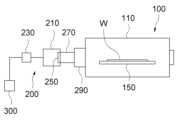
도 1은 본 발명의 일 실시예에 따른 에피택셜 성장장치에 대한 개념도이고, 도 2는 도 1의 에피택셜 성장장치의 일부 구성을 보인 사시도이다.1 is a conceptual diagram of an epitaxial growth apparatus according to an embodiment of the present invention, and FIG. 2 is a perspective view showing some components of the epitaxial growth apparatus of FIG. 1 .
본 도면들을 참조하면, 에피택셜 성장장치(100)는, 반응 챔버(110), 서셉터(150), 다층 가스공급 모듈(200), 그리고 소스 모듈(300)을 포함할 수 있다.Referring to the drawings, the
반응 챔버(110)는 에피택셜 반응이 일어나는 반응 공간을 갖는 구성이다. 반응 공간은, 도면상 간단히 네모 박스로 표시되어 있으나, 구체적으로는 하부 하우징(미도시)과 상부 하우징(미도시)이 상하 방향으로 서로 마주보고 배치된 것일 수 있다. 하부 하우징과 하부 하우징은 석영 유리와 같이 투명한 재질로 형성될 수 있다. 반응 공간의 좌측으로는 다층 가스공급 모듈(200)을 통해 가스 공급이 이루어지고, 우측으로는 가스 배출이 이루어질 수 있다.The
서셉터(150)는 반응 공간에 위치하며 웨이퍼(W)가 안착되는 대상이 된다. 서셉터(150)는 평탄한 원판 형상을 가질 수 있다. 서셉터(150)는 카본 그래파이트(Carbon graphite) 또는 카본 그래파이트에 탄화규소가 코팅된 재료로 제작될 수 있다. 또한, 웨이퍼(W)는 8 인치 이상의 크기를 가져서, 대면적으로 분류되는 것이다.The
다층 가스공급 모듈(200)은 반응 챔버(110) 내로 가스를 제공하며, 해당 가스의 유동을 조절하는 구성이다. 다층 가스공급 모듈(200)은, 인젝터(210), 유량배분 유닛(230), 배플(250), 인서트(270), 및 라이너(290)를 포함할 수 있다.The multi-layer
인젝터(210)는 소스 모듈(300)로부터 입력된 가스를 반응 챔버(110)를 향한 방향으로 토출하는 구성이다. 인젝터(210)는 층별로 서로 다른 가스를 출력하는 복수 층의 포트들(211,212,213)을 구비할 수 있다.The
제1 층의 포트들(211)은 웨이퍼(W)에 에피택셜 층을 형성하기 위한 원료 가스를 토출하기 위한 것일 수 있다. 제1 층의 포트들(211)은 웨이퍼(W)의 표면보다 0.5 내지 1mm 위에 설치될 수 있다. 그 경우, 제1 층의 포트들(211)을 통해 채버(110) 내로 주입된 가스는 웨이퍼(W)의 열에 의하여 웨이퍼(W)의 표면에 흡착될 수 있다. 예를 들어, 탄화실리콘 에피택셜 층을 형성하는 경우에, 상기 원료 가스는 실리콘, 탄소가 될 수 있다. 이들은 운반 가스인 수소 가스와 함께 제1 층의 포트들(211)에서 토출될 수 있으며, 질소 및 알루미늄도 토출될 수 있다.The
실리콘 원료 가스로는 SiH4, SiHCl3, SiHCl2, SiCl4, Si2H6 등 실리콘이 포함된 가스 중 어느 것일 수 있다. 탄소 원료 가스는 C2H2, C2H4, CH4, C2H5OH, CH3OH, C3H8 등 탄소 및 수소를 포함한 탄화수소 계열의 가스일 수 있다. 불순물로 주입되는 물질로서는 N type일 경우 질소, P-type일 경우 알루미늄이 사용될 수 있다. 상기 불순물 가스는 제1 층의 포트들(211)에서 원료 가스와 동시에, 또는 약간의 시간 차를 두고 토출될 수 있다. 이상에 더하여, 제1 층의 포트들(211)은 HCl, N2, Al, Ar 등 SiC 성장에 필요한 가스를 토출할 수도 있다.The silicon raw material gas may be any of silicon-containing gases such as SiH4 , SiHCl3 , SiHCl2 , SiCl4 , and Si2 H6 . The carbon source gas may be a hydrocarbon-based gas including carbon and hydrogen, such as C2 H2 , C2 H4 , CH4 , C2 H5 OH, CH3 OH, and C3 H8 . As a material implanted as an impurity, nitrogen may be used in the case of N type, and aluminum may be used in case of P-type. The impurity gas may be discharged from the
제2 층의 포트들(212)은 제1 층의 포트들(211) 보다 상층에 위치한다. 제2 층의 포트들(212)은 상기 원료 가스가 상방으로 분산되는 것을 차단하는 차단 가스를 토출할 수 있다. 상기 차단 가스는, 예를 들어 탄화실리콘 에피택셜층 성장 공정에 있어서, 수소 가스일 수 있다. 수소 가스는 웨이퍼(W) 위에서 수소 차단막(수소 돔)을 형성한다. 그에 따라, 제1 층의 포트들(211)에서 토출된 가스는 상기 수소 차단막에 막혀서 챔버(110)의 상부 공간으로 확산되지 않는다. 이는 상기 원료 가스가 웨이퍼(W)에만 위치하게 하여, 웨이퍼(W)에 작용하는 상기 원료 가스의 가스 농도를 효과적으로 높일 수 있게 한다. 이로 인해, 턴화실리콘 에피택셜 층의 성장 속도가 분당 25㎛ 이상이 될 수 있다. 제2 층의 포트들(212)은 웨이퍼(W)의 표면보다 1.5 내지 3mm 위에 설치될 수 있다. 그 경우, 토출된 수소 가스는 웨이퍼(W)의 표면에 흡착되지 않고 웨이퍼(W)의 상측에 효과적으로 차단막을 형성할 수 있다.The
제3 층의 포트들(213)은 제1 층의 포트들(211)의 하측에 배치된다. 제3 층의 포트들(213)은 부산물을 정화하는 정화 가스를 토출하는 것이다. 상기 부산물은 에피택셜 층의 성장 시에 발생하는 것이다. 상기 정화 가스는 아르곤 가스일 수 있다. 상기 정화 가스는 에피택셜 층의 성장이 종료되는 시점에 투입될 수 있다. 제3 층의 포트들(213)은 웨이퍼(W)의 표면보다 0.2 내지 0.4mm 위에 설치될 수 있다.The
나아가, 제3 층의 포트들(213)은 수소와 CHX(주로 C3H8) 계열의 탄화수소 가스를 토출할 수도 있다. SiC 성장 시에 P-type 또는 N-type 그리고 반절연 SiC를 성장할 시에 고려해야 하는 공정변수는 C/Si 비율이다. 제1 층의 포트들(211)에서 토출되는 실리콘과 탄화수소의 비율이 적정하지 않을 시에, 제3 층의 포트들(213)에서 탄소 가스를 추가로 토출하여 C/Si 비율을 조정할 수 있다. C/Si 비율은 0.6~2.7까지의 비율을 맞추어야 P-type 또는 N-type 그리고 반절연 SiC를 용도에 맞게 성장시킬 수 있다. 여기서, 수소는 탄소 가스를 운반하기 위한 역할이다.Furthermore, the
제1 층의 포트들(211) 내지 제3 층의 포트들(213)에 있어서, 각 층의 포트들은 웨이퍼(W)의 영역에 대응하는 포트들(216,217,218)로 구분될 수 있다. 이에 대해서는 도 3을 참조하여 설명한다.In the
유량배분 유닛(230)은 인젝터(210)에 입력되는 가스 유량을 인젝터(210)의 포트 별로 배분하는 구성이다. 상기 영역별 가스 유량은 서로 독립적일 수 있다. 이 역시 도 3을 참조하여 구체적으로 설명한다.The
다시 도 1 및 도 2를 참조하면, 배플(250)은 인젝터(210)를 통해 입력된 가스가 통과하는 통과홀들(251,253,255)을 구비하는 구성이다. 통과홀들(251,253,255)의 형상은 인젝터(210)의 포트들(211,212,213/216,217,218)에 따라 다르게 형성될 수 있다. 이는 도 4 내지 도 7에서 보다 구체적으로 설명한다.Referring back to FIGS. 1 and 2 , the
다시 도 1 및 도 2를 참조하면, 인서트(270)는 배플(250)과 라이너(290) 사이에 되어, 배플(250)을 통과한 가스를 라이너(290)로 안내하는 구성이다. 인서트(270) 역시 가스를 통과시키는 복수의 구역들을 가질 수 있다.Referring back to FIGS. 1 and 2 , the
라이너(290)는 서셉터(150)를 둘러싸서 가스가 웨이퍼(W)로 유동하도록 유도하는 구성이다. 그를 위해, 라이너(290)는 대체로 링 형상을 가질 수 있다. 라이너(290)의 일측에는 가스가 웨이퍼(W)를 향해 유입되는 부분이, 그리고 타측에는 가스가 웨이퍼(W)를 벗어나 배출되는 부분이 형성된다.The
소스 모듈(300)은 반응 챔버(110)에 공급되어야 하는 가스를 저장하는 가스 탱크이거나, 그와 연결된 중간 분배기일 수 있다.The
이하에서, 인젝터(210) 및 유량배분 유닛(230)에 대해서는 도 3을 참조하여 설명한다. 도 3은 도 2의 인젝터 관련 구성을 보인 횡 단면도이다.Hereinafter, the
본 도면을 추가로 참조하면, 인젝터(210), 구체적으로 그의 개별 층의 포트들(211,212,213)은, 센터 포트(216), 엣지 포트(217), 그리고 미들 포트(218)를 가질 수 있다.Referring further to this figure, the
센터 포트(216)는 웨이퍼(W)의 중앙 영역에 대응하여 위치한다. 엣지 포트(217)는 웨이퍼(W)의 양측 가장자리 영역에 대응하여 한 쌍으로 구비될 수 있다. 미들 포트(218)는 센터 포트(216)와 엣지 포트(217) 사이에 배치될 수 있다. 미들 포트(218) 역시 센터 포트(216)를 기준으로 좌우 양측에 배치되는 한 쌍으로 구비될 수 있다. 센터 포트(216)의 중심을 지나는 가상의 선(L)에 대하여, 센터 포트(216)의 좌우 부분들, 한 쌍의 엣지 포트(217) 및 한 쌍의 미들 포트(218)는 서로 대칭적인 배치를 이룰 수 있다. 센터 포트(216), 엣지 포트(217), 그리고 미들 포트(218)는 서로 동일한 폭(도면상 좌우 방향을 따르는 길이)을 가질 수 있다. 나아가, 미들 포트(218) 없이, 센터 포트(216)와 한 쌍의 엣지 포트(217) 만으로 구성될 수도 있다. 그 경우, 센터 포트(216)와 엣지 포트(217)의 영역이 미들 포트(218)를 커버하도록 커질 수 있다. The
유량배분 유닛(230)은 유입 라인(231)과 분기 라인(235)을 가질 수 있다. 유입 라인(231)은 소스 모듈(300)에 연통되어 가스를 입력받는 하나의(단일) 라인이다. 그에 반해, 분기 라인(235)는 유입 라인(231)에서 분기되어, 각 포트들(211,212,213/216,217,218)에 연결된다.The
유량배분 유닛(230)은 포트들(211,212,213/216,217,218) 각각에 연결된 유량제어기(Mass Flow Controller, 미도시)를 가질 수 있다. 상기 유량제어기 각각에 대한 설정을 통해서, 각 포트들(211,212,213/216,217,218)에 대한 가스의 투입량이 독립적으로 배분될 수 있다. 예를 들어, 센터 포트(216)에 대한 투입량을 제일 낮게 하고, 한 쌍의 엣지 포트(217)에 대한 투입량을 가장 높게 할 수 있다. 한 쌍의 미들 포트(218)에 대한 투입량은 그들의 중간 수준이 될 수 있다. 유량배분 유닛(230)은 또한 한 쌍의 엣지 포트(217)와 한 쌍의 미들 포트(218)에서의 투입량이 센터 포트(216)를 기준으로 서로 대칭되게 가스를 배분할 수 있다.The
다음으로, 인젝터(210)를 통해 복수의 영역으로 구분되어 토출되는 가스를 반응 챔버(110) 측을 향해 통과시키는 배플(250)에 대해 도 4 내지 도 7을 참조하여 설명한다.Next, the
먼저, 도 4는 도 2의 배플과 인젝터에 대한 정면도이다.First, FIG. 4 is a front view of the baffle and injector of FIG. 2 .
본 도면을 참조하면, 각 포트들(211,212,213/216,217,218)에서 토출된 가스는 배플(250)의 통과홀들(251,253,255)을 통과하게 된다.Referring to this figure, the gas discharged from the
통과홀들(251,253,255)은, 제1 층의 통과홀들(251), 제2 층의 통과홀들(253), 그리고 제3 층의 통과홀들(255)을 가질 수 있다. 제1 층의 통과홀들(251)은 제1 층의 포트들(211)에 대응하여 위치한다. 제2 층의 통과홀들(253)은 제2 층의 포트들(212)에 대응하여 위치하고, 역시 제3 층의 통과홀들(255)은 제3 층의 포트들(213)에 대응하여 위치한다.The passage holes 251 , 253 , and 255 may include passage holes 251 of the first layer, passage holes 253 of the second layer, and passage holes 255 of the third layer. The through
제2 층의 통과홀들(253)은 센터 포트(216), 미들 포트(218), 및 엣지 포트(217)에 대해 대응하는 위치에서 고른 크기를 가진다. 그에 반해, 제1 층의 통과홀들(251) 및 제3 층의 통과홀들(255)은 센터 포트(216)에 대응하는 것에서 엣지 포트(217)에 대응하는 것으로 갈수록 크기가 작아질 수 있다. 이는 제2 층의 통과홀들(253)을 통과하는 차단 가스는 영역과 무관하게 많은 양으로 챔버(110)에 주입되고, 제1 층의 통과홀들(251) 및 제3 층의 통과홀들(255)을 통과하는 원료 가스 및 정화 가스는 웨이퍼(W)의 영역 별로 다른 속도로 주입될 수 있도록 하기 위함이다. 구체적으로, 웨이퍼(W)의 중앙 보다는 가장자리에서 가스의 유속이 느려지는 바, 센터 포트(216)에서 엣지 포트(217)에 대응하는 위치로 갈수록 통과홀들의 사이즈를 줄여서 그를 통과하는 가스의 유속을 보상할 수 있다.The through
다음으로, 도 5는 도 4의 센터 포트들 및 대응하는 통과홀들의 형상을 보인 단면도이고, 도 6은 도 4의 미들 포트들 및 대응하는 통과홀들의 형상을 보인 단면도이며, 도 7은 도 4의 엣지 포트들 및 대응하는 통과홀들의 형상을 보인 단면도이다.Next, FIG. 5 is a cross-sectional view showing the shapes of the center ports and corresponding through-holes of FIG. 4, FIG. 6 is a cross-sectional view showing the shapes of the middle ports and corresponding through-holes of FIG. 4, and FIG. It is a cross-sectional view showing the shape of edge ports and corresponding through-holes.
본 도면들을 참조하면, 제1 층의 포트들(211) 내지 제3 층의 포트들(213) 모두에서, 센터 포트(216), 미들 포트(218), 그리고 엣지 포트(217)는 서로 균일한 사이즈를 가질 수 있다. 또한, 제2 층의 통과홀들(253) 중 센터 포트(216), 미들 포트(218), 그리고 엣지 포트(217)에 대응하는 것들 역시 서로 동일한 사이즈를 가질 수 있다. 그들은 원통 형상을 가져서, 각자의 입력단에서 출력단까지 폭(직경)의 변화가 없는 것이다.Referring to the drawings, in all of the
그에 반해, 제1 층의 통과홀들(251)과 제3 층의 통과홀들(255)은 원통 형상인 것과 콘(cone) 형상인 것이 서로 섞여 있다. 구체적으로, 센터 포트(216)에 대응하는 통과홀들(251,255)은 실린더 형상이나, 엣지 포트(217) 및 미들 포트(218)에 대응하는 통과홀들(251,255)은 콘 형상일 수 있다.In contrast, the through-
센터 포트(216)에 대응하는 통과홀들(251,253,255)은 제2 층의 통과홀들(253)에서 제1 층의 통과홀들(251)을 거쳐서 제3 층의 통과홀들(255)을 향한 방향으로 폭이 작아진다. 이러한 관계는 미들 포트(218)에 대응하는 통과홀들(251,253,255)과 엣지 포트(217)에 대응하는 통과홀들(251,253,255)에서도 동일하게 적용될 수 있다. 이러한 관계는 웨이퍼(W)에 근접하는 높이일수록 주입되는 가스의 속도가 높아지게 한다.The through
상기와 같은 에피택셜 성장장치 및 그에 사용되는 다층 가스공급 모듈은 위에서 설명된 실시예들의 구성과 작동 방식에 한정되는 것이 아니다. 상기 실시예들은 각 실시예들의 전부 또는 일부가 선택적으로 조합되어 다양한 변형이 이루어질 수 있도록 구성될 수도 있다.The epitaxial growth apparatus as described above and the multi-layer gas supply module used therein are not limited to the configuration and operation method of the embodiments described above. The above embodiments may be configured so that various modifications can be made by selectively combining all or part of each embodiment.
100: 에피택셜 성장장치110: 반응 챔버
150: 서셉터200: 다층 가스공급 모듈
210: 인젝터230: 유량배분 유닛
250: 배플270: 인서트
290: 라이너100: epitaxial growth device 110: reaction chamber
150: susceptor 200: multi-layer gas supply module
210: injector 230: flow distribution unit
250: baffle 270: insert
290: liner
Claims (11)
Translated fromKorean상기 반응 챔버 내에 위치하고, 웨이퍼가 안착되는 서셉터; 및
상기 웨이퍼에 에피택셜 층을 형성하기 위해 상기 반응 챔버에 대해 가스를 공급하는 다층 가스공급 모듈을 포함하고,
상기 다층 가스공급 모듈은,
층별로 서로 다른 가스를 토출하는 복수 층의 포트들을 구비하고, 상기 복수 층의 포트들 중 각 층의 포트들은 상기 웨이퍼의 중앙 영역에 대응하는 센터 포트와 상기 웨이퍼의 양측 가장자리 영역에 대응하는 한 쌍의 엣지 포트 그리고 상기 센터 포트와 상기 한 쌍의 엣지 포트 사이에 각각 배치되는 한 쌍의 미들 포트를 구비하고, 상기 센터 포트와 상기 미들 포트 및 상기 엣지 포트는 서로 동일한 폭을 갖는, 인젝터;
소스 모듈로부터 상기 가스를 입력받는 단일 유입 라인과, 상기 단일 유입 라인에서 분기되어 상기 포트들 각각에 직접 연결되는 복수의 분기 라인과 상기 포트들 각각에 연결된 유량제어기(Mass Flow Controller)들을 구비하여, 상기 가스를 상기 포트들에 대해 독립적으로 배분하도록 구성되는 유량배분 유닛; 및
상기 인젝터의 전방에 위치하여 상기 포트들에서 토출된 가스를 통과시키는 통과홀들을 구비하고, 상기 통과홀들 중에서 상기 복수 층의 포트들 중 적어도 한 층의 포트들에 대응하는 통과홀들은 서로 다르게 형성되는, 배플을 포함하는, 에피택셜 성장장치.
reaction chamber;
a susceptor located in the reaction chamber and on which a wafer is seated; and
a multi-layer gas supply module supplying gas to the reaction chamber to form an epitaxial layer on the wafer;
The multi-layer gas supply module,
Each layer has a plurality of layers of ports for discharging different gases, and among the plurality of layers of ports, the ports of each layer include a center port corresponding to the central area of the wafer and a pair of ports corresponding to both side edge areas of the wafer. An injector having an edge port of and a pair of middle ports respectively disposed between the center port and the pair of edge ports, wherein the center port, the middle port, and the edge port have the same width as each other;
A single inlet line for receiving the gas from the source module, a plurality of branch lines branched off from the single inlet line and directly connected to each of the ports, and mass flow controllers connected to each of the ports, a flow distribution unit configured to independently distribute the gas to the ports; and
It is located in front of the injector and has through-holes through which gas discharged from the ports passes, and among the through-holes, the through-holes corresponding to the ports of at least one layer among the ports of the plurality of layers are formed differently from each other. An epitaxial growth apparatus comprising a baffle to be.
상기 복수 층의 포트들은,
상기 에피택셜 층을 형성하는 원료 가스를 토출하는 제1 층의 포트들; 및
상기 제1 층의 포트들 보다 상측에 위치하고, 상기 원료 가스의 상방 확산을 차단하는 차단 가스를 토출하는 제2 층의 포트들을 포함하는, 에피택셜 성장장치.
According to claim 1,
The multiple layers of ports,
ports of the first layer for discharging source gas forming the epitaxial layer; and
Located above the ports of the first layer and including ports of the second layer for discharging a blocking gas to block the upward diffusion of the source gas, the epitaxial growth apparatus.
상기 복수 층의 포트들은,
상기 제1 층의 포트들의 하측에 배치되고, 상기 에피택셜 층의 성장시에 발생하는 부산물을 정화하는 정화 가스를 토출하는 제3 층의 포트들을 더 포함하는, 에피택셜 성장장치.
According to claim 2,
The multiple layers of ports,
The epitaxial growth apparatus further comprises ports of a third layer disposed below the ports of the first layer and discharging a purge gas for purifying by-products generated during growth of the epitaxial layer.
상기 통과홀들은,
상기 제1 층의 포트들에 대응하는 제1 층의 통과홀들;
상기 제2 층의 포트들에 대응하는 제2 층의 통과홀들; 및
상기 제3 층의 포트들에 대응하는 제3 층의 통과홀들을 포함하고,
상기 제2 층의 통과홀들은,
원통 형상을 갖고,
상기 제1 층의 통과홀들 및 상기 제3층의 통과홀들은,
원통 형상인 것과 콘 형상인 것이 섞여 있는, 에피택셜 성장장치.
According to claim 3,
The passage holes are
passage holes of the first layer corresponding to the ports of the first layer;
passage holes of the second layer corresponding to the ports of the second layer; and
Including through-holes of the third layer corresponding to the ports of the third layer,
The passage holes of the second layer,
has a cylindrical shape,
The passage holes of the first layer and the passage holes of the third layer,
An epitaxial growth device in which a cylindrical shape and a cone shape are mixed.
상기 제1 층의 통과홀들 및 상기 제3층의 통과홀들 중 상기 센터 포트에 대응하는 통과홀들은 원통 형상을 갖고,
상기 제1 층의 통과홀들 및 상기 제3층의 통과홀들 중 상기 엣지 포트에 대응하는 통과홀들은 콘 형상을 갖는, 에피택셜 성장장치.
According to claim 4,
Among the passage holes of the first layer and the passage holes of the third layer, passage holes corresponding to the center port have a cylindrical shape,
Of the through-holes of the first layer and the through-holes of the third layer, the through-holes corresponding to the edge ports have a cone shape.
상기 제3 층의 통과홀들은,
상기 제1 층의 통과홀들에 비해 작은 단면 크기를 갖는, 에피택셜 성장장치.
According to claim 4,
The passage holes of the third layer,
Having a small cross-sectional size compared to the through-holes of the first layer, the epitaxial growth device.
층별로 서로 다른 가스를 토출하는 복수 층의 포트들을 구비하고, 상기 복수 층의 포트들 중 각 층의 포트들은 웨이퍼의 중앙 영역에 대응하는 센터 포트와 상기 웨이퍼의 양측 가장자리 영역에 대응하는 한 쌍의 엣지 포트 그리고 상기 센터 포트와 상기 한 쌍의 엣지 포트 사이에 각각 배치되는 한 쌍의 미들 포트를 구비하고, 상기 센터 포트와 상기 미들 포트 및 상기 엣지 포트는 서로 동일한 폭을 갖는, 인젝터; 및
상기 가스를 생성하는 소스 모듈로부터 상기 가스를 입력받는 단일 유입 라인과, 상기 단일 유입 라인에서 분기되어 상기 포트들 각각에 직접 연결되는 복수의 분기 라인과 상기 포트들 각각에 연결된 유량제어기(Mass Flow Controller)들을 구비하여, 상기 가스를 상기 포트들에 대해 독립적으로 배분하도록 구성되는 유량배분 유닛; 및
상기 인젝터의 전방에 위치하여 상기 포트들에서 토출된 가스를 통과시키는 통과홀들을 구비하고, 상기 통과홀들 중에서 상기 복수 층의 포트들 중 적어도 한 층의 포트들에 대응하는 통과홀들은 서로 다르게 형성되는, 배플을 포함하는, 에피택셜 성장장치용 다층 가스공급 모듈.
A multi-layer gas supply module for supplying gas introduced into the reaction chamber of the epitaxial growth apparatus,
Each layer has a plurality of layers of ports for discharging different gases, and among the plurality of layers of ports, the ports of each layer include a center port corresponding to the central area of the wafer and a pair of ports corresponding to both edge areas of the wafer. an injector comprising an edge port and a pair of middle ports respectively disposed between the center port and the pair of edge ports, wherein the center port, the middle port, and the edge port have the same width; and
A single inlet line receiving the gas from the source module generating the gas, a plurality of branch lines branched off from the single inlet line and directly connected to each of the ports, and a mass flow controller connected to each of the ports. ), the flow distribution unit configured to independently distribute the gas to the ports; and
It is located in front of the injector and has through-holes through which gas discharged from the ports passes, and among the through-holes, the through-holes corresponding to the ports of at least one layer among the ports of the plurality of layers are formed differently from each other. A multi-layer gas supply module for an epitaxial growth apparatus comprising a baffle.
상기 복수 층의 포트들은,
에피택셜 층을 형성하는 원료 가스를 토출하는 제1 층의 포트들; 및
상기 제1 층의 포트들 보다 상측에 위치하고, 상기 원료 가스의 상방 확산을 차단하는 차단 가스를 토출하는 제2 층의 포트들을 포함하는, 에피택셜 성장장치용 다층 가스공급 모듈.
According to claim 7,
The multiple layers of ports,
ports of the first layer for discharging source gas forming the epitaxial layer; and
A multi-layer gas supply module for an epitaxial growth apparatus, including ports of a second layer located above the ports of the first layer and discharging a blocking gas for blocking upward diffusion of the source gas.
상기 통과홀들은,
상기 제1 층의 포트들에 대응하는 제1 층의 통과홀들; 및
상기 제2 층의 포트들에 대응하는 제2 층의 통과홀들을 포함하고,
상기 제2 층의 통과홀들은,
원통 형상을 갖고,
상기 제1 층의 통과홀들은,
원통 형상인 것과 콘 형상인 것이 섞여 있는, 에피택셜 성장장치용 다층 가스공급 모듈.According to claim 8,
The passage holes are
passage holes of the first layer corresponding to the ports of the first layer; and
Including through-holes of the second layer corresponding to the ports of the second layer,
The passage holes of the second layer,
has a cylindrical shape,
The passage holes of the first layer,
A multi-layer gas supply module for epitaxial growth equipment in which a cylindrical shape and a cone shape are mixed.
Priority Applications (4)
| Application Number | Priority Date | Filing Date | Title |
|---|---|---|---|
| KR1020220167459AKR102572439B1 (en) | 2022-12-05 | 2022-12-05 | Epitaxial growth apparatus and multi-layer gas supply module used therefor |
| EP23209367.4AEP4407076A1 (en) | 2022-12-05 | 2023-11-13 | Epitaxial growth apparatus and multi-layer gas supply module used therefor |
| JP2023193945AJP7665714B2 (en) | 2022-12-05 | 2023-11-14 | Epitaxial growth apparatus and multi-layer gas supply module used therein |
| US18/511,096US20240183036A1 (en) | 2022-12-05 | 2023-11-16 | Epitaxial growth apparatus and multi-layer gas supply module used therefor |
Applications Claiming Priority (1)
| Application Number | Priority Date | Filing Date | Title |
|---|---|---|---|
| KR1020220167459AKR102572439B1 (en) | 2022-12-05 | 2022-12-05 | Epitaxial growth apparatus and multi-layer gas supply module used therefor |
Publications (1)
| Publication Number | Publication Date |
|---|---|
| KR102572439B1true KR102572439B1 (en) | 2023-08-30 |
Family
ID=87846118
Family Applications (1)
| Application Number | Title | Priority Date | Filing Date |
|---|---|---|---|
| KR1020220167459AActiveKR102572439B1 (en) | 2022-12-05 | 2022-12-05 | Epitaxial growth apparatus and multi-layer gas supply module used therefor |
Country Status (4)
| Country | Link |
|---|---|
| US (1) | US20240183036A1 (en) |
| EP (1) | EP4407076A1 (en) |
| JP (1) | JP7665714B2 (en) |
| KR (1) | KR102572439B1 (en) |
Citations (5)
| Publication number | Priority date | Publication date | Assignee | Title |
|---|---|---|---|---|
| KR20130080151A (en)* | 2012-01-04 | 2013-07-12 | 주식회사 엘지실트론 | Adjust unit of injecting flow and vapor deposition apparatus including the same |
| JP2015173226A (en)* | 2014-03-12 | 2015-10-01 | 株式会社アルバック | Vacuum deposition apparatus and deposition method using this apparatus |
| KR20170048562A (en)* | 2014-09-05 | 2017-05-08 | 어플라이드 머티어리얼스, 인코포레이티드 | Inject insert for epi chamber |
| KR20190092282A (en)* | 2018-01-30 | 2019-08-07 | 헤르메스 에피텍 코포레이션 | Gas injector for cvd system |
| KR20220046805A (en)* | 2020-10-08 | 2022-04-15 | 에스케이실트론 주식회사 | Epitaxial growth apparatus |
Family Cites Families (8)
| Publication number | Priority date | Publication date | Assignee | Title |
|---|---|---|---|---|
| JP5413305B2 (en)* | 2010-05-25 | 2014-02-12 | 信越半導体株式会社 | Epitaxial growth equipment |
| JP5481415B2 (en)* | 2011-03-09 | 2014-04-23 | 株式会社東芝 | Vapor growth apparatus and vapor growth method |
| JP5837178B2 (en)* | 2011-03-22 | 2015-12-24 | アプライド マテリアルズ インコーポレイテッドApplied Materials,Incorporated | Liner assembly for chemical vapor deposition chambers |
| US9255346B2 (en)* | 2011-05-27 | 2016-02-09 | Crystal Solar, Incorporated | Silicon wafers by epitaxial deposition |
| JP6170340B2 (en)* | 2013-05-21 | 2017-07-26 | 東京エレクトロン株式会社 | Gas supply head, gas supply mechanism, and substrate processing apparatus |
| KR101487409B1 (en)* | 2013-07-19 | 2015-01-29 | 주식회사 엘지실트론 | An epitaxial reactor |
| KR102127715B1 (en)* | 2013-08-09 | 2020-06-29 | 에스케이실트론 주식회사 | An epitaxial reactor |
| CN110088876A (en)* | 2016-11-22 | 2019-08-02 | 威科仪器有限公司 | Thickness Uniformity Control for Epitaxially Grown Structures in a Chemical Vapor Deposition System |
- 2022
- 2022-12-05KRKR1020220167459Apatent/KR102572439B1/enactiveActive
- 2023
- 2023-11-13EPEP23209367.4Apatent/EP4407076A1/enactivePending
- 2023-11-14JPJP2023193945Apatent/JP7665714B2/enactiveActive
- 2023-11-16USUS18/511,096patent/US20240183036A1/enactivePending
Patent Citations (5)
| Publication number | Priority date | Publication date | Assignee | Title |
|---|---|---|---|---|
| KR20130080151A (en)* | 2012-01-04 | 2013-07-12 | 주식회사 엘지실트론 | Adjust unit of injecting flow and vapor deposition apparatus including the same |
| JP2015173226A (en)* | 2014-03-12 | 2015-10-01 | 株式会社アルバック | Vacuum deposition apparatus and deposition method using this apparatus |
| KR20170048562A (en)* | 2014-09-05 | 2017-05-08 | 어플라이드 머티어리얼스, 인코포레이티드 | Inject insert for epi chamber |
| KR20190092282A (en)* | 2018-01-30 | 2019-08-07 | 헤르메스 에피텍 코포레이션 | Gas injector for cvd system |
| KR20220046805A (en)* | 2020-10-08 | 2022-04-15 | 에스케이실트론 주식회사 | Epitaxial growth apparatus |
Also Published As
| Publication number | Publication date |
|---|---|
| EP4407076A1 (en) | 2024-07-31 |
| JP2024081127A (en) | 2024-06-17 |
| US20240183036A1 (en) | 2024-06-06 |
| JP7665714B2 (en) | 2025-04-21 |
Similar Documents
| Publication | Publication Date | Title |
|---|---|---|
| EP1043763B1 (en) | Vapor growth apparatus for semiconductor wafers with dopant gas feed assembly | |
| KR102349875B1 (en) | Gas distribution system, reactor including the system, and methods of using the same | |
| CN107690487B (en) | Injector for semiconductor epitaxial growth | |
| CN104756231B (en) | Epitaxy chamber with customizable flow implant | |
| EP0502209B1 (en) | Method and apparatus for growing compound semiconductor crystals | |
| US5525157A (en) | Gas injectors for reaction chambers in CVD systems | |
| US8349403B2 (en) | Vapor-phase process apparatus, vapor-phase process method, and substrate | |
| US20030015137A1 (en) | Chemical vapor deposition apparatus and chemical vapor deposition method | |
| US6746941B2 (en) | Semiconductor wafer and production method therefor | |
| US20160145766A1 (en) | Epitaxial reactor | |
| KR102572439B1 (en) | Epitaxial growth apparatus and multi-layer gas supply module used therefor | |
| KR102811576B1 (en) | Gas injectors for epitaxy and CVD chambers | |
| KR102572438B1 (en) | Epitaxial growth apparatus and gas supply control module used therefor | |
| JP6987215B2 (en) | Injection assembly for epitaxial deposition process | |
| CN109661716B (en) | Vapor phase growth apparatus, method for manufacturing epitaxial wafer, and attachment for vapor phase growth apparatus | |
| JPWO2005093136A1 (en) | Support and semiconductor substrate processing method | |
| CN109661715B (en) | Vapor phase growth apparatus and epitaxial wafer manufacturing method | |
| JPH05226263A (en) | Vapor phase silicon epitaxial growth device | |
| JP3010739B2 (en) | Method and apparatus for growing compound semiconductor crystal | |
| GB2404668A (en) | A method and system for manufacturing III-V group compound semiconductors |
Legal Events
| Date | Code | Title | Description |
|---|---|---|---|
| PA0109 | Patent application | Patent event code:PA01091R01D Comment text:Patent Application Patent event date:20221205 | |
| PA0201 | Request for examination | ||
| PA0302 | Request for accelerated examination | Patent event date:20221205 Patent event code:PA03022R01D Comment text:Request for Accelerated Examination | |
| PE0902 | Notice of grounds for rejection | Comment text:Notification of reason for refusal Patent event date:20230210 Patent event code:PE09021S01D | |
| AMND | Amendment | ||
| PE0601 | Decision on rejection of patent | Patent event date:20230525 Comment text:Decision to Refuse Application Patent event code:PE06012S01D Patent event date:20230210 Comment text:Notification of reason for refusal Patent event code:PE06011S01I | |
| X091 | Application refused [patent] | ||
| AMND | Amendment | ||
| PX0901 | Re-examination | Patent event code:PX09011S01I Patent event date:20230525 Comment text:Decision to Refuse Application Patent event code:PX09012R01I Patent event date:20230316 Comment text:Amendment to Specification, etc. | |
| PX0701 | Decision of registration after re-examination | Patent event date:20230814 Comment text:Decision to Grant Registration Patent event code:PX07013S01D Patent event date:20230713 Comment text:Amendment to Specification, etc. Patent event code:PX07012R01I Patent event date:20230525 Comment text:Decision to Refuse Application Patent event code:PX07011S01I Patent event date:20230316 Comment text:Amendment to Specification, etc. Patent event code:PX07012R01I | |
| X701 | Decision to grant (after re-examination) | ||
| GRNT | Written decision to grant | ||
| PR0701 | Registration of establishment | Comment text:Registration of Establishment Patent event date:20230825 Patent event code:PR07011E01D | |
| PR1002 | Payment of registration fee | Payment date:20230825 End annual number:3 Start annual number:1 | |
| PG1601 | Publication of registration |