KR102571929B1 - Forceps for Tissue Excision - Google Patents
Forceps for Tissue ExcisionDownload PDFInfo
- Publication number
- KR102571929B1 KR102571929B1KR1020210079227AKR20210079227AKR102571929B1KR 102571929 B1KR102571929 B1KR 102571929B1KR 1020210079227 AKR1020210079227 AKR 1020210079227AKR 20210079227 AKR20210079227 AKR 20210079227AKR 102571929 B1KR102571929 B1KR 102571929B1
- Authority
- KR
- South Korea
- Prior art keywords
- cup
- forceps
- tissue
- coupled
- forceps cup
- Prior art date
- Legal status (The legal status is an assumption and is not a legal conclusion. Google has not performed a legal analysis and makes no representation as to the accuracy of the status listed.)
- Active
Links
- 238000003306harvestingMethods0.000claimsabstractdescription18
- 239000013013elastic materialSubstances0.000claimsabstractdescription5
- XLYOFNOQVPJJNP-UHFFFAOYSA-NwaterSubstancesOXLYOFNOQVPJJNP-UHFFFAOYSA-N0.000claimsdescription15
- 238000000926separation methodMethods0.000claimsdescription12
- 239000002952polymeric resinSubstances0.000claimsdescription6
- 229920003002synthetic resinPolymers0.000claimsdescription6
- 238000002679ablationMethods0.000claimsdescription4
- 230000008878couplingEffects0.000claimsdescription4
- 238000010168coupling processMethods0.000claimsdescription4
- 238000005859coupling reactionMethods0.000claimsdescription4
- 238000002271resectionMethods0.000abstractdescription6
- 238000001574biopsyMethods0.000description10
- 230000000694effectsEffects0.000description9
- 238000007599dischargingMethods0.000description3
- 210000003811fingerAnatomy0.000description3
- 230000014509gene expressionEffects0.000description3
- 210000000056organAnatomy0.000description3
- 239000011248coating agentSubstances0.000description2
- 238000000576coating methodMethods0.000description2
- 238000000605extractionMethods0.000description2
- 239000000463materialSubstances0.000description2
- 238000012986modificationMethods0.000description2
- 230000004048modificationEffects0.000description2
- TWDJIKFUVRYBJF-UHFFFAOYSA-NCyanthoateChemical compoundCCOP(=O)(OCC)SCC(=O)NC(C)(C)C#NTWDJIKFUVRYBJF-UHFFFAOYSA-N0.000description1
- 238000005452bendingMethods0.000description1
- 201000010099diseaseDiseases0.000description1
- 208000037265diseases, disorders, signs and symptomsDiseases0.000description1
- 239000003814drugSubstances0.000description1
- 238000005516engineering processMethods0.000description1
- 239000004744fabricSubstances0.000description1
- 229920005989resinPolymers0.000description1
- 239000011347resinSubstances0.000description1
- 238000005070samplingMethods0.000description1
- 210000003813thumbAnatomy0.000description1
- 210000001835visceraAnatomy0.000description1
Images


Classifications
- A—HUMAN NECESSITIES
- A61—MEDICAL OR VETERINARY SCIENCE; HYGIENE
- A61B—DIAGNOSIS; SURGERY; IDENTIFICATION
- A61B10/00—Instruments for taking body samples for diagnostic purposes; Other methods or instruments for diagnosis, e.g. for vaccination diagnosis, sex determination or ovulation-period determination; Throat striking implements
- A61B10/02—Instruments for taking cell samples or for biopsy
- A61B10/06—Biopsy forceps, e.g. with cup-shaped jaws
- A—HUMAN NECESSITIES
- A61—MEDICAL OR VETERINARY SCIENCE; HYGIENE
- A61B—DIAGNOSIS; SURGERY; IDENTIFICATION
- A61B10/00—Instruments for taking body samples for diagnostic purposes; Other methods or instruments for diagnosis, e.g. for vaccination diagnosis, sex determination or ovulation-period determination; Throat striking implements
- A61B10/02—Instruments for taking cell samples or for biopsy
- A61B10/0233—Pointed or sharp biopsy instruments
- A61B10/0266—Pointed or sharp biopsy instruments means for severing sample
- A61B10/0275—Pointed or sharp biopsy instruments means for severing sample with sample notch, e.g. on the side of inner stylet
- A—HUMAN NECESSITIES
- A61—MEDICAL OR VETERINARY SCIENCE; HYGIENE
- A61B—DIAGNOSIS; SURGERY; IDENTIFICATION
- A61B10/00—Instruments for taking body samples for diagnostic purposes; Other methods or instruments for diagnosis, e.g. for vaccination diagnosis, sex determination or ovulation-period determination; Throat striking implements
- A61B10/02—Instruments for taking cell samples or for biopsy
- A61B10/04—Endoscopic instruments, e.g. catheter-type instruments
- A—HUMAN NECESSITIES
- A61—MEDICAL OR VETERINARY SCIENCE; HYGIENE
- A61B—DIAGNOSIS; SURGERY; IDENTIFICATION
- A61B17/00—Surgical instruments, devices or methods
- A61B17/28—Surgical forceps
- A61B17/29—Forceps for use in minimally invasive surgery
- A61B17/295—Forceps for use in minimally invasive surgery combined with cutting implements
- A—HUMAN NECESSITIES
- A61—MEDICAL OR VETERINARY SCIENCE; HYGIENE
- A61B—DIAGNOSIS; SURGERY; IDENTIFICATION
- A61B17/00—Surgical instruments, devices or methods
- A61B17/32—Surgical cutting instruments
- A61B17/3205—Excision instruments
Landscapes
- Health & Medical Sciences (AREA)
- Life Sciences & Earth Sciences (AREA)
- Surgery (AREA)
- Heart & Thoracic Surgery (AREA)
- Molecular Biology (AREA)
- Veterinary Medicine (AREA)
- Engineering & Computer Science (AREA)
- Biomedical Technology (AREA)
- Public Health (AREA)
- Medical Informatics (AREA)
- General Health & Medical Sciences (AREA)
- Animal Behavior & Ethology (AREA)
- Nuclear Medicine, Radiotherapy & Molecular Imaging (AREA)
- Pathology (AREA)
- Biodiversity & Conservation Biology (AREA)
- Radiology & Medical Imaging (AREA)
- Ophthalmology & Optometry (AREA)
- Surgical Instruments (AREA)
Abstract
Translated fromKorean
Description
Translated fromKorean본 발명은 조직 절제용 포셉에 관한 것으로서, 더욱 상세하게는 제1 포셉컵이 소정 각도 이상으로 회전하면, 제1 포셉컵의 회전방향과 동일한 방향으로 제2 포셉컵이 함께 회전함으로써 채취대상 조직이 제1 포셉컵과 제2 포셉컵의 중앙에 배치되어 조직 채취효율을 향상시키는 한편, 제1 컵부 및 제2 컵부에 의해 채취된 조직에 포함된 수분이 수분배출공을 통해 배출되어 보다 많은 양의 조직의 채취가 가능하도록 하고, 채취된 조직과 제1 컵부 및 제2 컵부의 접촉면적을 최소화하여 제1 컵부 및 제2 컵부에 채취된 조직이 제1 컵부 및 제2 컵부로부터 잘 분리되도록 하며, 분리부재를 통해 제1 포셉컵과 제2 포셉컵 사이의 마찰을 방지함과 동시에, 제1 구동와이어와 제2 구동와이어를 분리시켜 꼬임을 방지하는 조직 절제용 포셉에 관한 것이다.The present invention relates to forceps for tissue excision, and more particularly, when a first forceps cup is rotated at a predetermined angle or more, the second forceps cup rotates in the same direction as the rotational direction of the first forceps cup, so that the tissue to be harvested is removed. It is placed in the center of the first forceps cup and the second forceps cup to improve the tissue collection efficiency, while the moisture contained in the tissue collected by the first and second cups is discharged through the water discharge hole to obtain a larger amount of tissue. enabling tissue collection, and minimizing the contact area between the collected tissue and the first cup portion and the second cup portion so that the tissue collected in the first cup portion and the second cup portion is well separated from the first cup portion and the second cup portion; The present invention relates to forceps for tissue ablation that prevent friction between a first forceps cup and a second forceps cup through a separation member and prevent twisting by separating a first driving wire and a second driving wire.
일반적으로, 의료용 내시경은 장기나 체강 등에 삽입되어 내부 장기와 체강 등의 모양이나 상태를 관찰하는 의료 기기로서, 현재까지 의학의 발전에 공헌을 하고 있다. In general, a medical endoscope is a medical device that is inserted into an organ or a body cavity to observe the shape or condition of an internal organ or a body cavity, and has contributed to the development of medicine.
이러한 내시경에는 체내의 장기나 체강 등을 관찰하는 기능 외에 체내 조직을 채취하는 바이옵시(biopsy) 기능이 구비되어, 내시경으로부터 회수되는 체내 조직을 조직학적으로 검사하여 질병의 유무 또는 그 진행 정도를 진단할 수 있다.These endoscopes are equipped with a biopsy function to collect body tissues in addition to the function of observing organs or body cavities in the body, and histologically examine the body tissues recovered from the endoscope to diagnose the presence or absence of disease or its progress can do.
바이옵시 포셉은 바이옵시 채널을 통하여 체내로 삽입되고, 체외에서 시술자가 바이옵시 포셉을 조작하여 체내 조직을 채취한 후에 바이옵시 포셉을 체외로 꺼내서 조직을 회수한다.The biopsy forceps are inserted into the body through the biopsies channel, and the operator manipulates the biopsies forceps outside the body to collect body tissue, and then takes the biopsies forceps out of the body to recover the tissue.
바이옵시 포셉은 대부분 내시경에서 인출시 시술자가 포셉 조작부를 계속해서 손가락으로 가압하여 채취된 조직이 망실되지 않도록 홀딩해서 사용한다.Most of the biopsy forceps are used by holding them so that the extracted tissue is not lost by the operator continuously pressing the forceps control part with a finger when withdrawing from the endoscope.
채취하고자 하는 조직이 벌어진 포셉 사이의 중앙에 위치했을 때는 채취효율이 가장 높다.The extraction efficiency is highest when the tissue to be harvested is located in the center between the separated forceps.
그러나 채취할 조직이 체내에 구석진 위치 또는 포셉이 접근하기 어려운 위치일 경우, 종래의 포셉으로는 이와 같은 경우의 조직을 정확하게 채취하기가 어려웠다.However, when the tissue to be harvested is located in a corner of the body or is difficult to access with forceps, it is difficult to accurately collect the tissue in such a case with conventional forceps.
한편, 조직검사를 위해서는 일정량 이상의 조직이 채취되어야 한다.On the other hand, for a biopsy, more than a certain amount of tissue must be collected.
그러나 체내에는 조직뿐만 아니라 수분도 함께 존재하므로, 조직과 함께 상당량의 수분이 함께 채취된다.However, since not only tissues but also water exist in the body, a significant amount of water is collected together with tissues.
이 때 채취되는 수분량이 많으면 조직검사에 필요한 일정량의 조직이 채취되지 못하는 경우가 종종 발생한다.At this time, if the amount of moisture collected is high, it often occurs that a certain amount of tissue required for biopsy cannot be collected.
즉 조직과 수분이 함께 포셉에 채취되는 경우 조직보다 수분이 많으면 채취효율이 떨어지는 문제점이 있다.That is, when tissue and moisture are collected together with the forceps, there is a problem in that the collection efficiency is lowered when there is more moisture than tissue.
때문에 수분이 배제된 상태로 조직만을 정확하게 채취할 수 있는 포셉의 개발이 필요하다.Therefore, it is necessary to develop forceps that can accurately collect only tissue while excluding moisture.
통상적으로 포셉의 개폐는 포셉과 결합된 와이어에 의해 움직인다.Typically, opening and closing of the forceps is moved by a wire coupled with the forceps.
포셉의 개폐를 조작할 때 와이어의 당김에 의해 포셉의 개폐동작이 결정되므로 와이어가 꼬이거나 꺾이지 않도록 주의하여야 한다.When opening and closing the forceps, since the opening and closing operation of the forceps is determined by the pulling of the wire, care must be taken not to twist or bend the wire.
따라서, 채취하고자 하는 조직의 위치에 상관없이 조직을 정확하게 채취 가능하면서, 수분이 배제된 상태로 조직을 채취할 수 있으며, 포셉 개폐동작시 와이어가 꼬이지 않도록 설계된 새로운 조직 절제용 포셉의 개발이 절실히 요구된다.Therefore, there is an urgent need to develop new forceps for tissue excision, which can accurately collect tissue regardless of the location of the tissue to be harvested, while removing moisture, and designed to prevent the wire from being twisted during the opening and closing operation of the forceps. do.
본 발명은 상기와 같은 문제를 해결하고자 제안된 것으로, 제1 포셉컵이 소정 각도 이상으로 회전하면, 제1 포셉컵의 회전방향과 동일한 방향으로 제2 포셉컵이 함께 회전함으로써 채취대상 조직이 제1 포셉컵과 제2 포셉컵의 중앙에 배치되어 조직 채취효율을 향상시키는 것을 목적으로 한다.The present invention has been proposed to solve the above problems. When the first forceps cup rotates at a predetermined angle or more, the second forceps cup rotates in the same direction as the rotational direction of the first forceps cup, so that the tissue to be harvested is collected. It is placed in the center of the 1 forceps cup and the 2nd forceps cup to improve the efficiency of tissue extraction.
또한 본 발명은 제1 컵부 및 제2 컵부에 의해 채취된 조직에 포함된 수분이 수분배출공을 통해 배출되어 보다 많은 양의 조직의 채취가 가능하도록 하는 것을 목적으로 한다.In addition, an object of the present invention is to make it possible to collect a larger amount of tissue by discharging the moisture contained in the tissues collected by the first and second cup portions through a moisture discharge hole.
또한 본 발명은 채취된 조직과 제1 컵부 및 제2 컵부의 접촉면적을 최소화하여 제1 컵부 및 제2 컵부에 채취된 조직이 제1 컵부 및 제2 컵부로부터 잘 분리되도록 하는 것을 목적으로 한다.Another object of the present invention is to minimize the contact area between the collected tissues and the first cup portion and the second cup portion so that the collected tissues are well separated from the first cup portion and the second cup portion.
또한 본 발명은 분리부재를 통해 제1 포셉컵과 제2 포셉컵 사이의 마찰을 방지하는 것을 목적으로 한다.Another object of the present invention is to prevent friction between the first forceps cup and the second forceps cup through the separation member.
또한 본 발명은 제1 구동와이어와 제2 구동와이어를 분리시켜 꼬임을 방지하는 것을 목적으로 한다.Another object of the present invention is to separate the first drive wire and the second drive wire to prevent twisting.
또한 본 발명은 제1 구동와이어 및 제2 구동와이어의 표면은 고분자 수지로 코팅되어 제1 구동와이어와 제2 구동와이어 사이에 발생하는 마찰을 최소화하는 것을 목적으로 한다.In addition, an object of the present invention is to minimize friction generated between the first driving wire and the second driving wire by coating the surfaces of the first driving wire and the second driving wire with a polymer resin.
본 발명은 조직 절제용 포셉에 관한 것으로, The present invention relates to forceps for tissue resection,
내부에 중공부가 형성된 원기둥 형상으로 형성된 본체;A main body formed in a cylindrical shape with a hollow part formed therein;
상기 본체의 하단부에 결합되되, 탄성 재질의 파이프 형상으로 형성되어 조직채취부를 이동시키기 위한 힘을 전달하는 탄성튜브;An elastic tube coupled to the lower end of the main body and formed in a pipe shape made of an elastic material to transmit force for moving the tissue collection unit;
상기 본체에 결합되어 조직채취부의 채취동작을 조종하는 조작부;a manipulation unit coupled to the main body to control a harvesting operation of the tissue harvesting unit;
상기 탄성튜브의 단부에 결합되어 조직을 채취하는 조직채취부;를 포함하는 것을 특징으로 한다.It is characterized in that it comprises a; tissue collection unit coupled to the end of the elastic tube to collect tissue.
또한 본 발명의 상기 조직채취부는,In addition, the tissue collection unit of the present invention,
오목한 컵 형상으로 형성된 제1 컵부의 가장자리를 따라 칼날이 형성되고, 상기 제1 컵부의 하방향으로는 상기 제1 컵부를 지지하는 제1 지지부가 연장되어 형성된 제1 포셉컵;a first forceps cup having a blade formed along an edge of a first cup portion formed in a concave cup shape, and extending a first support portion supporting the first cup portion in a downward direction of the first cup portion;
오목한 컵 형상으로 형성된 제2 컵부의 가장자리를 따라 칼날이 형성되고, 상기 제2 컵부의 하방향으로는 상기 제2 컵부를 지지하는 제2 지지부가 연장되어 형성되되, 상기 제2 지지부에서 제1 포셉컵의 제1 지지부와 X자형으로 교차되어 대향되도록 결합되는 제2 포셉컵;A blade is formed along the edge of the second cup portion formed in a concave cup shape, and a second support portion supporting the second cup portion extends in a downward direction of the second cup portion, and the first cloth is formed from the second support portion. a second forceps cup coupled to face the first support portion of the septum cup in an X-shape;
상기 제1 포셉컵과 제2 포셉컵이 교차되는 부분을 둘러싸되, 하단부는 상기 탄성튜브에 결합되는 하우징;a housing surrounding a portion where the first forceps cup and the second forceps cup intersect, and having a lower end coupled to the elastic tube;
상기 제1 포셉컵과 제2 포셉컵이 교차되는 부분에서 상기 제1 포셉컵, 제2 포셉컵, 그리고 상기 하우징을 관통하여 결합되는 힌지핀;을 포함하는 것을 특징으로 한다.and a hinge pin coupled through the first forceps cup, the second forceps cup, and the housing at a portion where the first forceps cup and the second forceps cup intersect.
또한 본 발명의 상기 제1 지지부는 상기 제1 컵부의 하단부 일측에 제1 단턱이 형성되고, 타측에는 상기 제1 컵부의 길이방향을 따라 연장되는 제1 연장부가 형성되며,In addition, the first support portion of the present invention has a first step formed on one side of the lower end of the first cup portion, and a first extension portion extending along the longitudinal direction of the first cup portion is formed on the other side,
상기 제2 지지부는 상기 제2 컵부의 하단부 일측에 상기 제1 연장부와 대향하도록 제2 단턱이 형성되고, 타측에는 상기 제2 컵부의 길이방향을 따라 연장되되 상기 제1 단턱과 대향하도록 제2 연장부가 형성되고,The second support portion has a second step formed on one side of the lower end of the second cup portion to face the first extension portion, and on the other side thereof, a second step extending along the longitudinal direction of the second cup portion and facing the first step portion. An extension is formed,
상기 제1 포셉컵이 소정 각도 이상으로 회전하면, 제1 포셉컵의 제1 단턱이 제2 포셉컵의 제2 연장부에 걸려 상기 제1 포셉컵의 회전방향과 동일한 방향으로 제2 포셉컵이 함께 회전하는 것을 특징으로 한다.When the first forceps cup rotates beyond a predetermined angle, the first step of the first forceps cup is caught on the second extension of the second forceps cup, and the second forceps cup rotates in the same direction as the rotation direction of the first forceps cup. It is characterized by rotating together.
또한 본 발명의 상기 제1 컵부 및 제2 컵부에는,In addition, in the first cup part and the second cup part of the present invention,
수분이 배출 가능하도록 소정 직경의 수분배출공;이 형성되며,A moisture discharge hole having a predetermined diameter is formed so that moisture can be discharged,
상기 제1 컵부 및 제2 컵부에 의해 채취된 조직에 포함된 수분이 상기 수분배출공을 통해 배출되어 보다 많은 양의 조직의 채취가 가능하도록 하고, 채취된 조직과 상기 제1 컵부 및 제2 컵부의 접촉면적을 최소화하여 상기 제1 컵부 및 제2 컵부에 채취된 조직이 상기 제1 컵부 및 제2 컵부로부터 잘 분리되도록 하는 것을 특징으로 한다.The moisture contained in the tissue collected by the first cup part and the second cup part is discharged through the water discharge hole so that a larger amount of tissue can be collected, and the collected tissue and the first cup part and the second cup It is characterized in that the contact area of the parts is minimized so that tissues collected in the first cup part and the second cup part are well separated from the first cup part and the second cup part.
또한 본 발명은 판재 형상으로 형성되되 상부에는 상기 힌지핀과 결합되도록 결합공이 형성되며, 상기 제1 포셉컵과 제2 포셉컵 사이에 배치되는 분리부재;를 더 포함하며,In addition, the present invention further includes a separation member formed in a plate shape, having a coupling hole formed at an upper portion to be coupled with the hinge pin, and disposed between the first forceps cup and the second forceps cup,
상기 분리부재를 통해 제1 포셉컵과 제2 포셉컵 사이의 마찰을 방지함과 동시에, 상기 제1 구동와이어와 제2 구동와이어를 분리시켜 꼬임을 방지하는 것을 특징으로 한다.It is characterized in that the friction between the first forceps cup and the second forceps cup is prevented through the separation member, and twisting is prevented by separating the first driving wire and the second driving wire.
또한 본 발명의 상기 조작부는,In addition, the operation unit of the present invention,
링 형상으로 형상되어상기 본체 상을 주행 가능하도록 결합된 슬라이더;a slider formed in a ring shape and coupled to be able to travel on the main body;
일단은 상기 제1 포셉컵 및 제2 포셉컵에 각각 결합되고 타단은 상기 슬라이더에 결합되어, 상기 슬라이더의 이동에 따라 상기 제1 포셉컵 및 제2 포셉컵을 개폐시키는 제1 구동와이어 및 제2 구동와이어;를 포함하는 것을 특징으로 한다.A first drive wire and a second drive wire having one end coupled to the first and second forceps cups and the other end coupled to the slider to open and close the first and second forceps cups according to the movement of the slider. Characterized in that it comprises a; drive wire.
또한 본 발명의 상기 제1 구동와이어 및 제2 구동와이어의 표면은 고분자 수지로 코팅되어 제1 구동와이어와 제2 구동와이어 사이에 발생하는 마찰을 최소화하는 것을 특징으로 한다.In addition, the surfaces of the first drive wire and the second drive wire of the present invention are coated with a polymer resin to minimize friction between the first drive wire and the second drive wire.
본 발명에 따른 조직 절제용 포셉은 제1 포셉컵이 소정 각도 이상으로 회전하면, 제1 포셉컵의 회전방향과 동일한 방향으로 제2 포셉컵이 함께 회전함으로써 조직이 제1 포셉컵과 제2 포셉컵의 중앙에 배치되어 조직 채취효율을 향상시키는 효과가 있다.In the forceps for tissue excision according to the present invention, when the first forceps cup rotates beyond a predetermined angle, the second forceps cup rotates in the same direction as the rotational direction of the first forceps cup, so that the tissue is separated from the first forceps cup and the second forceps cup. It is placed in the center of the sepcup and has the effect of improving tissue harvesting efficiency.
또한 본 발명은 제1 컵부 및 제2 컵부에 의해 채취된 조직에 포함된 수분이 수분배출공을 통해 배출되어 보다 많은 양의 조직의 채취가 가능하도록 하는 효과가 있다.In addition, the present invention has the effect of allowing a greater amount of tissue to be collected by discharging the moisture contained in the tissue collected by the first cup part and the second cup part through the water discharge hole.
또한 본 발명은 채취된 조직과 제1 컵부 및 제2 컵부의 접촉면적을 최소화하여 제1 컵부 및 제2 컵부에 채취된 조직이 제1 컵부 및 제2 컵부로부터 잘 분리되도록 하는 효과가 있다.In addition, the present invention has an effect of minimizing the contact area between the collected tissue and the first cup portion and the second cup portion so that the collected tissue from the first cup portion and the second cup portion is well separated from the first cup portion and the second cup portion.
또한 본 발명은 분리부재를 통해 제1 포셉컵과 제2 포셉컵 사이의 마찰을 방지하는 효과가 있다.In addition, the present invention has an effect of preventing friction between the first forceps cup and the second forceps cup through the separation member.
또한 본 발명은 제1 구동와이어와 제2 구동와이어를 분리시켜 꼬임을 방지하는 효과가 있다.In addition, the present invention has the effect of preventing twisting by separating the first drive wire and the second drive wire.
또한 본 발명은 제1 구동와이어 및 제2 구동와이어의 표면은 고분자 수지로 코팅되어 제1 구동와이어와 제2 구동와이어 사이에 발생하는 마찰을 최소화하는 효과가 있다.In addition, the surface of the first drive wire and the second drive wire of the present invention is coated with a polymer resin to minimize friction between the first drive wire and the second drive wire.
상술한 효과와 더불어 본 발명의 구체적인 효과는 이하 발명을 실시하기 위한 구체적인 사항을 설명하면서 함께 기술한다.In addition to the effects described above, specific effects of the present invention will be described together while explaining specific details for carrying out the present invention.
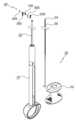
도 1은 본 발명에 따른 조직 절제용 포셉의 사시도이다.
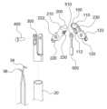
도 2는 본 발명에 따른 조직 절제용 포셉의 분해도이다.
도 3은 본 발명에 따른 조직채취부의 상세도이다.
도 4는 본 발명에 따른 조직채취부의 분해도이다.
도 5는 본 발명에 따른 조직채취부가 회전하여 일측에 위치한 조직을 채취하는 동작을 나타내는 도면이다.1 is a perspective view of a forceps for tissue resection according to the present invention.
2 is an exploded view of the forceps for tissue resection according to the present invention.
Figure 3 is a detailed view of the tissue harvesting unit according to the present invention.
Figure 4 is an exploded view of the tissue harvesting unit according to the present invention.
5 is a view showing an operation of collecting tissue located on one side by rotating the tissue harvesting unit according to the present invention.
이하, 본 문서의 다양한 실시예가 첨부된 도면을 참조하여 기재된다. 그러나 이는 본 문서에 기재된 기술을 특정한 실시 형태에 대해 한정하려는 것이 아니며, 본 문서의 실시예의 다양한 변경(modifications), 균등물(equivalents), 및/또는 대체물(alternatives)을 포함하는 것으로 이해되어야 한다. 도면의 설명과 관련하여, 유사한 구성요소에 대해서는 유사한 참조 부호가 사용될 수 있다.Hereinafter, various embodiments of this document will be described with reference to the accompanying drawings. However, this is not intended to limit the technology described in this document to specific embodiments, and is to be understood as including various modifications, equivalents, and/or alternatives of the embodiments of this document. In connection with the description of the drawings, like reference numerals may be used for like elements.
또한, 본 문서에서 사용된 "제1," "제2," 등의 표현들은 다양한 구성요소들을, 순서 및/또는 중요도에 상관없이 수식할 수 있고, 한 구성요소를 다른 구성요소와 구분하기 위해 사용될 뿐 해당 구성요소들을 한정하지 않는다. 예를 들면, '제1 부분'과 '제2 부분'은 순서 또는 중요도와 무관하게, 서로 다른 부분을 나타낼 수 있다. 예를 들면, 본 문서에 기재된 권리 범위를 벗어나지 않으면서 제1 구성요소는 제2 구성요소로 명명될 수 있고, 유사하게 제2 구성요소도 제1 구성요소로 바꾸어 명명될 수 있다.In addition, expressions such as “first,” “second,” etc. used in this document may modify various components regardless of order and/or importance, and to distinguish one component from another. It is used only and does not limit the corresponding components. For example, 'first part' and 'second part' may indicate different parts regardless of order or importance. For example, without departing from the scope of rights described in this document, a first element may be called a second element, and similarly, the second element may also be renamed to the first element.
또한, 본 문서에서 사용된 용어들은 단지 특정한 실시예를 설명하기 위해 사용된 것으로, 다른 실시예의 범위를 한정하려는 의도가 아닐 수 있다. 단수의 표현은 문맥상 명백하게 다르게 뜻하지 않는 한, 복수의 표현을 포함할 수 있다. 기술적이거나 과학적인 용어를 포함해서 여기서 사용되는 용어들은 본 문서에 기재된 기술 분야에서 통상의 지식을 가진 자에 의해 일반적으로 이해되는 것과 동일한 의미를 가질 수 있다. 본 문서에 사용된 용어들 중 일반적인 사전에 정의된 용어들은, 관련 기술의 문맥상 가지는 의미와 동일 또는 유사한 의미로 해석될 수 있으며, 본 문서에서 명백하게 정의되지 않는 한, 이상적이거나 과도하게 형식적인 의미로 해석되지 않는다. 경우에 따라서, 본 문서에서 정의된 용어일지라도 본 문서의 실시예들을 배제하도록 해석될 수 없다.In addition, terms used in this document are only used to describe a specific embodiment, and may not be intended to limit the scope of other embodiments. Singular expressions may include plural expressions unless the context clearly dictates otherwise. Terms used herein, including technical or scientific terms, may have the same meaning as commonly understood by a person of ordinary skill in the technical field described in this document. Among the terms used in this document, terms defined in a general dictionary may be interpreted as having the same or similar meaning as the meaning in the context of the related art, and unless explicitly defined in this document, an ideal or excessively formal meaning. not be interpreted as In some cases, even terms defined in this document cannot be interpreted to exclude the embodiments of this document.
도 1은 본 발명에 따른 조직 절제용 포셉의 사시도이며, 도 2는 본 발명에 따른 조직 절제용 포셉의 분해도이다.1 is a perspective view of forceps for tissue resection according to the present invention, and FIG. 2 is an exploded view of the forceps for tissue resection according to the present invention.
본 발명은 체내의 장기나 체강 등에 삽입되어 체내 채취대상 조직(A)을 채취하는 포셉에 관한 것이다.The present invention relates to a forceps that is inserted into an organ or a body cavity in the body and collects a tissue (A) to be collected from the body.
본 발명에 따른 조직 절제용 포셉은 본체(10), 탄성튜브(20), 조작부(30), 조직채취부(40)를 주요 구성으로 한다.Forceps for tissue excision according to the present invention has a
도 1 내지 도 2에 도시된 바와 같이, 본체(10)는 내부에 중공부가 형성된 원기둥 형상으로 형상된다.As shown in FIGS. 1 and 2 , the
본체(10)의 하단부에는 링 형상으로 시술자의 손가락을 삽입 가능하도록 형성된다.The lower end of the
탄성튜브(20)는 본체(10)의 상단부에 결합된다.
탄성튜브(20)는 탄성 재질의 파이프 형상으로 형성되어 조직채취부(40)를 이동하기 위한 힘을 전달하는 구성이다.The
탄성튜브(20)는 체내 삽입시 접힘 또는 꺽임 현상이 방지되도록 원형 복원이 가능한 탄성재질로 형성되어야 한다.The
본 발명에 따른 탄성튜브(20)의 내측에는 코일스프링이 삽입되고 겉면에는 유연한 재질의 수지가 코일스프링을 둘러싸도록 형성되어 체내 삽입시 상처가 나지 않도록 형성된다.A coil spring is inserted into the inner side of the
탄성튜브(20)의 내측에 코일스프링이 삽입됨으로써 탄성튜브(20)를 삽입할 때 힘이 코일스프링을 통해 전달된다.Since the coil spring is inserted inside the
만일 코일스프링이 내장되지 않고 유연한 재질로만 탄성튜브(20)가 제작된다면 삽입시 힘이 제대로 전달되지 않게 된다.If the coil spring is not built in and the
조작부(30)는 본체(10)에 결합되어 조직채취부(40)의 채취동작을 조종한다.The
조작부(30)는 슬라이더(32), 제1 구동와이어(34), 제2 구동와이어(36)로 구성된다.The
도 1에 도시된 바와 같이, 슬라이더(32)는 링 형상으로 형성되어 본체(10) 상을 주행 가능하도록 결합된다.As shown in FIG. 1 , the
제1 구동와이어(34)의 일단에는 제1 포셉컵(100)이 결합되고 타단에는 슬라이더(32)와 결합된다.The
마찬가지로 제2 구동와이어(36)의 일단에는 제2 포셉컵(200)이 결합되고 타탄에는 슬라이더(32)와 결합된다.Similarly, the
제1 구동와이어(34)와 제2 구동와이어(36)와 결합된 슬라이더(32)의 이동에 따라 제1 포셉컵(100) 및 제2 포셉컵(200)이 개폐된다.The
슬라이더(32)를 본체(10)의 길이방향을 따라 이동하기 위해서는 본체(10) 단부에 형성된 링에 엄지손가락을 삽입하고 검지와 중지로 슬라이더(32)를 파지하여 조종한다.To move the
슬라이더(32)를 본체(10) 하단부로 이동시키면 슬라이더(32)와 결합된 제1 구동와이어(34) 및 제2 구동와이어(36)에 의해 제1 포셉컵(100) 및 제2 포셉컵(200)이 오므려진다.When the
반대로, 슬라이더(32)를 본체(10) 상단부로 이동시키면 슬라이더(32)와 결합된 제1 구동와이어(34) 및 제2 구동와이어(36)에 의해 제1 포셉컵(100) 및 제2 포셉컵(200)이 소정 각도로 벌어진다.Conversely, when the
이와 같이 슬라이더(32)에 의해 제1 구동와이어(34) 및 제2 구동와이어(36)가 탄성튜브(20) 내에서 길이방향을 따라 이송한다.In this way, the
이 때 제1 구동와이어(34) 및 제2 구동와이어(36)가 포셉컵의 개폐동작을 결정하므로 제1 구동와이어(34)와 제2 구동와이어(36)가 꼬이거나 꺾이지 않도록 주의하여야 한다.At this time, since the
제1 구동와이어(34) 및 제2 구동와이어(36)가 꼬이거나 꺾이게 되면, 포셉의 개폐가 원활하게 동작하지 않게 되어 체내에서 채취된 조직(A)을 망실하게 된다.When the
한편, 제1 구동와이어(34) 및 제2 구동와이어(36)의 이송동작에서 제1 구동와이어(34) 및 제2 구동와이어(36) 사이에 발생하는 마찰을 최소화하기 위해 제1 구동와이어(34) 및 제2 구동와이어(36)의 표면에 고분자 수지로 코팅을 하였다.On the other hand, in order to minimize friction generated between the
본 발명은 제1 구동와이어(34) 및 제2 구동와이어(36)의 표면에 고분자 수지로 코팅을 함으로써 제1 구동와이어(34) 및 제2 구동와이어(36)의 내구성을 향상시키도록 하였다.The present invention is to improve the durability of the
도 3은 본 발명에 따른 조직채취부의 상세도이고, 도 4는 본 발명에 따른 조직채취부의 분해도이며, 도 5는 본 발명에 따른 조직채취부가 회전하여 일측에 위치한 조직을 채취하는 동작을 나타내는 도면이다.Figure 3 is a detailed view of the tissue harvesting unit according to the present invention, Figure 4 is an exploded view of the tissue harvesting unit according to the present invention, Figure 5 is a view showing the operation of rotating the tissue harvesting unit according to the present invention to collect tissue located on one side am.
도 3 내지 도 5를 참조하여 조직채취부(40)에 대해 상세히 설명한다.Referring to Figures 3 to 5 will be described in detail with respect to the tissue harvesting unit (40).
조직채취부(40)는 탄성튜브(20)의 단부에 결합되어 조직(A)을 채취하는 구성이다.The
구체적으로 조직채취부(40)는 제1 포셉컵(100), 제2 포셉컵(200), 하우징(300), 힌지핀(400)으로 구성된다.Specifically, the
제1 포셉컵(100)은 오목한 컵 형상으로 형성된다.The
제1 포셉컵(100)은 오목한 컵 형상으로 형성된 제1 컵부(110)의 가장자리를 따라 칼날이 형성된다.In the
제1 컵부(110)의 하방향으로는 제1 컵부(110)를 지지하는 제1 지지부(120)가 연장되어 형성된다.A
마찬가지로, 제2 포셉컵(200) 또한 오목한 컵 형상으로 형성된다.Similarly, the
제2 포셉컵(200) 또한 오목한 컵 형상으로 형성된 제2 컵부(210)의 가장자리를 따라 칼날이 형성된다.In the
제1 컵부(110)의 칼날과 제2 컵부(210)의 칼날이 서로 맞물려 조직(A)이 채취된다.The blades of the
제2 컵부(210)의 하방향으로는 제2 컵부(210)를 지지하는 제2 지지부(220)가 연장되어 형성된다.A
제1 포셉컵(100)과 제2 포셉컵(200)은 동일한 형상으로 제작되되, 제1 지지부(120)와 제2 지지부(220)는 서로 반대측에 형성된다.The
제1 포셉컵(100)의 제1 지지부(120)와 제2 포셉컵(200)의 제2 지지부(220)가 X자형으로 교차되어 제1 컵부(110)와 제2 컵부(210)가 서로 대향되도록 결합된다.The
제1 포셉컵(100)과 제2 포셉컵(200)에 각각 결합된 제1 구동와이어(34)와 제2 구동와이어(36)에 의해 X자형으로 벌어지거나 오므려진다.It is opened or closed in an X shape by the
하우징(300)은 제1 포셉컵(100)과 제2 포셉컵(200)이 교차되는 부분을 둘러싸도록 형성된다.The
또한 하우징(300)의 하단부는 탄성튜브(20)에 결합된다.Also, the lower end of the
힌지핀(400)은 제1 포셉컵(100)과 제2 포셉컵(200)이 교차되는 부분에서 제1 포셉컵(100), 제2 포셉컵(200), 그리고 하우징(300)을 관통하여 결합된다.The
제1 포셉컵(100)과 제2 포셉컵(200)은 힌지핀(400)을 중심으로 X자형으로 교차되어 상대 회전이 가능하도록 결합된다.The
체내에 채취하고자 하는 조직(A)이 소정 각도로 벌어진 제1 포셉컵(100)과 제2 포셉컵(200) 사이의 중앙에 위치했을 때 채취효율이 가장 높다.The sampling efficiency is highest when the tissue (A) to be harvested is located in the center between the
그러나 채취할 조직(A)이 제1 포셉컵(100) 또는 제2 포셉컵(200)에 치우쳐져 위치할 경우, 종래의 포셉으로는 이와 같은 경우의 조직(A)을 정확하게 채취하기가 어려웠다.However, when the tissue A to be collected is located biasedly in the
이에 본 발명은 제1 포셉컵(100) 및 제2 포셉컵(200)이 치우져 위치된 조직쪽으로 함께 회전하도록 함으로써 종래의 문제점을 해소하였다.Accordingly, the present invention solves the conventional problem by allowing the
도 5를 참조하여 상세히 설명한다.It will be described in detail with reference to FIG. 5 .
제1 포셉컵(100)에는 제1 컵부(110)와 제1 지지부(120)가 구비된다.The
제2 포셉컵(200) 또한 제2 컵부(210)와 제2 지지부(220)가 구비된다.The
제1 지지부(120)에는 제1 컵부(110)의 하단부 일측에 제1 단턱(112)이 형성된다.A
그리고 제1 지지부(120)에는 제1 컵부(110)의 하단부 타측에 제1 컵부(110)의 길이방향을 따라 연장되는 제1 연장부(122)가 형성된다.In addition, a
제2 지지부(220)에는 제2 컵부(210)의 하단부 일측에 제2 단턱(212)이 형성되며, 제2 단턱(212)은 제1 연장부(122)와 대향하도록 형성된다.A
그리고 제2 지지부(220)에는 제2 컵부(210)의 하단부 타측에 제2 컵부(210)의 길이방향을 따라 연장되는 제2 연장부(222)가 형성되며, 제2 연장부(222)는 제1 단턱(112)과 대향하도록 형성된다.In addition, a
본 발명은 제1 포셉컵(100)이 소정 각도 이상으로 회전하면, 제1 포셉컵(100)의 제1 단턱(112)이 제2 포셉컵(200)의 제2 연장부(222)에 걸려 제1 포셉컵(100)의 회전방향과 동일한 방향으로 제2 포셉컵(200)이 함께 회전한다. 즉, 제1 단턱(112)과 제2 단턱(212)이 일종의 스토퍼의 역할을 하는 것이다.According to the present invention, when the
채취하고자 하는 조직(A)이 제1 포셉컵(100)에 가까이 위치한 경우를 예로 들어 설명한다.A case in which the tissue A to be harvested is located close to the
제1 포셉컵(100)을 채취대상 조직(A)이 가압되도록 밀어 넣으면 제1 포셉컵(100)의 내측에 채취대상 조직(A)이 접촉하게 된다.When the
이 때 와이어의 조작력에 의해 제1 포셉컵(100)이 반시계방향으로 회전한다. 이 때 제1 포셉컵(100)이 소정 각도 이상으로 회전하면 제1 포셉컵(100)의 제1 단턱(112)이 제2 포셉컵(200)의 제2 연장부(222)에 걸리게 되고, 제2 포셉컵(200)은 제1 포셉컵(100)의 회전방향과 동일한 방향으로 연동되어 회전한다.At this time, the
즉 채취대상 조직(A)의 위치로 조직채취부(40)를 밀어넣으면, 제1 포셉컵(100)과 제2 포셉컵(200)의 가운데로 채취대상 조직(A)이 위치하도록 제1 포셉컵(100)과 제2 포셉컵(200)이 함께 틸팅되어 조직 채취가 용이하게 되는 것이다.That is, when the
제1 포셉컵(100)과 제2 포셉컵(200) 사이의 중앙에 조직(A)이 위치하게 되면 동일한 각도로 제1 포셉컵(100)과 제2 포셉컵(200)이 오므려지면서 조직(A)을 정확하게 채취할 수 있다.When the tissue A is located in the center between the
따라서 본 발명은 이와 같은 구조를 통해 조직 채취의 시술성을 향상시키는 효과가 있다.Therefore, the present invention has the effect of improving the processability of tissue harvesting through such a structure.
한편, 조직검사를 위해서는 일정량 이상의 조직(A)이 채취되어야 한다.On the other hand, for a biopsy, more than a certain amount of tissue (A) must be collected.
그러나 체내에는 조직뿐만 아니라 수분도 함께 존재하므로, 조직(A)과 함께 다량의 수분이 함께 채취된다.However, since not only tissues but also water exist in the body, a large amount of water is collected together with the tissue (A).
이 때 채취되는 수분량이 많으면 조직검사에 필요한 일정량의 조직(A)이 채취되지 않는 경우가 종종 발생한다.At this time, if the amount of moisture collected is high, it often occurs that a certain amount of tissue (A) required for the biopsy is not collected.
즉 수분이 포함된 체내에서 조직(A)을 채취할 때 조직(A)과 수분이 함께 포셉컵에 채취되는 경우, 조직(A)보다 수분이 많으면 채취효율이 떨어지는 문제점이 있다.That is, when tissue (A) is collected from a body containing water, when the tissue (A) and water are collected together in a forceps cup, there is a problem in that the collection efficiency is lowered when the tissue (A) contains more moisture.
때문에 수분이 배제된 상태로 조직(A)만을 정확하게 집어 떼어낼 수 있는 포셉의 개발이 필요하다.Therefore, it is necessary to develop forceps that can accurately pick up and remove only the tissue (A) in a state in which moisture is excluded.
본 발명은 종래의 문제점을 해소하기 위해 제1 컵부(110) 및 제2 컵부(210)에 수분배출공(230)을 구비하였다.In order to solve the problems of the prior art, the present invention provided a
수분배출공(230)은 조직(A) 주변에 존재하는 수분이 제1 컵부(110) 및 제2 컵부(210) 밖으로 배출되도록 소정 직경으로 형성된다.The
본 발명은 제1 컵부(110) 및 제2 컵부(210)에 의해 채취된 조직(A)에 포함된 수분이 수분배출공(230)을 통해 배출되도록 함으로써 보다 많은 양의 조직(A)의 채취가 가능하도록 하였다.In the present invention, a greater amount of tissue A is collected by discharging the moisture contained in the tissue A collected by the
게다가, 수분배출공(230)은 채취된 조직(A)과 제1 컵부(110) 및 제2 컵부(210)의 접촉면적을 최소화하여 채취된 조직(A)이 제1 컵부(110) 및 제2 컵부(210)로부터 잘 분리되는 효과가 있다.In addition, the
제1 컵부(110) 및 제2 컵부(210) 상에 수분배출공(230)의 직경만큼 조직(A)과 접촉되는 면적이 줄어들게 되므로, 채취된 조직(A)이 제1 컵부(110) 및 제2 컵부(210)로부터 잘 분리되는 것이다.Since the area in contact with the tissue A is reduced by the diameter of the
한편, 조직채취부(40)에는 제1 포셉컵(100)과 제2 포셉컵(200) 사이에 분리부재(500)가 결합된다.Meanwhile, the
분리부재(500)는 판재 형상으로 형성된다.The separating
분리부재(500)의 상부에는 힌지핀(400)과 결합되도록 결합공(510)이 형성되어, 제1 포셉컵(100)과 제2 포셉컵(200) 사이에 배치된다.A
분리부재(500)는 제1 포셉컵(100)과 제2 포셉컵(200)이 벌려지거나 오므려지는 동작에서 발생하는 마찰을 방지한다.The
또한 분리부재(500)의 단부는 제1 구동와이어(34)와 제2 구동와이어(36) 사이에 배치되어 제1 구동와이어(34)와 제2 구동와이어(36)를 분리시킴으로써 와이어의 꼬임을 방지한다.In addition, the end of the
즉 분리부재(500)를 통해 제1 구동와이어(34)와 제2 구동와이어(36)를 분리시켜 꼬이지 않도록 하여 포셉컵의 개폐동작이 원활히 이루어지도록 한다.That is, the
본 발명은 조직 절제용 포셉에 관한 것으로서, 더욱 상세하게는 제1 포셉컵이 소정 각도 이상으로 회전하면, 제1 포셉컵의 회전방향과 동일한 방향으로 제2 포셉컵이 함께 회전함으로써 조직이 제1 포셉컵과 제2 포셉컵의 중앙에 배치되어 조직 채취효율을 향상시키는 한편, 제1 컵부 및 제2 컵부에 의해 채취된 조직에 포함된 수분이 수분배출공을 통해 배출되어 보다 많은 양의 조직의 채취가 가능하도록 하고, 채취된 조직과 제1 컵부 및 제2 컵부의 접촉면적을 최소화하여 채취된 조직이 제1 컵부 및 제2 컵부로부터 잘 분리되도록 하며, 분리부재를 통해 제1 포셉컵과 제2 포셉컵 사이의 마찰을 방지함과 동시에, 제1 구동와이어와 제2 구동와이어를 분리시켜 꼬임을 방지하는 조직 절제용 포셉에 관한 것이다.The present invention relates to forceps for tissue excision, and more particularly, when a first forceps cup is rotated at a predetermined angle or more, the second forceps cup rotates in the same direction as the rotational direction of the first forceps cup, so that tissue is separated into a first forceps cup. It is placed in the center of the forceps cup and the second forceps cup to improve the tissue collection efficiency, while the moisture contained in the tissue collected by the first cup and the second cup is discharged through the water discharge hole to obtain a larger amount of tissue. It enables collection, and minimizes the contact area between the collected tissue and the first cup part and the second cup part so that the collected tissue is well separated from the first cup part and the second cup part. 2 It relates to a forceps for tissue ablation that prevents friction between forceps cups and prevents twisting by separating a first driving wire and a second driving wire.
이상에서는 본 발명의 바람직한 실시예에 대하여 도시하고 설명하였지만, 본 발명은 상술한 특정의 실시예에 한정되지 아니하며, 청구범위에서 청구하는 본 발명의 요지를 벗어남이 없이 당해 발명이 속하는 기술분야에서 통상의 지식을 가진 자에 의해 다양한 변형실시가 가능한 것은 물론이고, 이러한 변형 실시예들은 본 발명의 기술적 사상이나 전망으로부터 개별적으로 이해되어서는 안 될 것이다.Although the preferred embodiments of the present invention have been shown and described above, the present invention is not limited to the specific embodiments described above, and is common in the art to which the present invention pertains without departing from the gist of the present invention claimed in the claims. Of course, various modifications are possible by those with knowledge of, and these modified embodiments should not be individually understood from the technical spirit or perspective of the present invention.
A : 채취대상 조직
10 : 본체
20 : 탄성튜브
30 : 조작부
32 : 슬라이더
34 : 제1 구동와이어
36 : 제2 구동와이어
40 : 조직채취부
100 : 제1 포셉컵
110 : 제1 컵부
112 : 제1 단턱
120 : 제1 지지부
122 : 제1 연장부
200 : 제2 포셉컵
210 : 제2 컵부
212 : 제2 단턱
220 : 제2 지지부
222 : 제2 연장부
230 : 수분배출공
300 : 하우징
400 : 힌지핀
500 : 분리부재
510 : 결합공A: Tissue to be collected
10: body
20: elastic tube
30: control panel
32 : Slider
34: first drive wire
36: second drive wire
40: tissue collection unit
100: 1st forceps cup
110: first cup part
112: first step
120: first support
122: first extension
200: 2nd forceps cup
210: second cup part
212: second step
220: second support
222: second extension
230: moisture discharge hole
300: housing
400: hinge pin
500: separation member
510: coupling hole
Claims (7)
Translated fromKorean상기 본체(10)의 상단부에 결합되되, 탄성 재질의 파이프 형상으로 형성되어 조직채취부(40)를 이동시키기 위한 힘을 전달하는 탄성튜브(20);
상기 본체(10)에 결합되어 조직채취부(40)의 채취동작을 조종하는 조작부(30);
상기 탄성튜브(20)의 단부에 결합되어 조직(A)을 채취하는 조직채취부(40);를 포함하며,
상기 조직채취부(40)는,
오목한 컵 형상으로 형성된 제1 컵부(110)의 가장자리를 따라 칼날이 형성되고, 상기 제1 컵부(110)의 하방향으로는 상기 제1 컵부(110)를 지지하는 제1 지지부(120)가 연장되어 형성된 제1 포셉컵(100);
오목한 컵 형상으로 형성된 제2 컵부(210)의 가장자리를 따라 칼날이 형성되고, 상기 제2 컵부(210)의 하방향으로는 상기 제2 컵부(210)를 지지하는 제2 지지부(220)가 연장되어 형성되되, 상기 제2 지지부(220)에서 제1 포셉컵(100)의 제1 지지부(120)와 X자형으로 교차되어 대향되도록 결합되는 제2 포셉컵(200);
상기 제1 포셉컵(100)과 제2 포셉컵(200)이 교차되는 부분을 둘러싸되, 하단부는 상기 탄성튜브(20)에 결합되는 하우징(300);
상기 제1 포셉컵(100)과 제2 포셉컵(200)이 교차되는 부분에서 상기 제1 포셉컵(100), 제2 포셉컵(200), 그리고 상기 하우징(300)을 관통하여 결합되는 힌지핀(400);을 포함하며,
판재 형상으로 형성되되 상부에는 상기 힌지핀(400)과 결합되도록 결합공(510)이 형성되며, 상기 제1 포셉컵(100)과 제2 포셉컵(200) 사이에 배치되는 분리부재(500);를 더 포함하며,
상기 분리부재(500)를 통해 제1 포셉컵(100)과 제2 포셉컵(200) 사이의 마찰을 방지하는 것을 특징으로 하는, 조직 절제용 포셉
A main body 10 formed in a cylindrical shape with a hollow part formed therein;
An elastic tube 20 coupled to the upper end of the main body 10 and formed in a pipe shape made of an elastic material to transmit force for moving the tissue collection unit 40;
a manipulation unit 30 coupled to the main body 10 and controlling a harvesting operation of the tissue harvesting unit 40;
A tissue collection unit 40 coupled to the end of the elastic tube 20 to collect tissue A; includes,
The tissue collection unit 40,
A blade is formed along the edge of the first cup portion 110 formed in a concave cup shape, and the first support portion 120 supporting the first cup portion 110 extends downward from the first cup portion 110. a first forceps cup 100 formed by being formed;
A blade is formed along the edge of the second cup portion 210 formed in a concave cup shape, and a second support portion 220 supporting the second cup portion 210 extends downward from the second cup portion 210. The second forceps cup 200 is formed by crossing the first support portion 120 of the first forceps cup 100 at the second support portion 220 in an X shape and coupled to face each other;
a housing 300 surrounding a portion where the first forceps cup 100 and the second forceps cup 200 intersect and having a lower end coupled to the elastic tube 20;
A hinge coupled through the first forceps cup 100, the second forceps cup 200, and the housing 300 at the intersection of the first forceps cup 100 and the second forceps cup 200 Including; pin 400;
A separation member 500 formed in a plate shape and having a coupling hole 510 formed thereon to be coupled with the hinge pin 400, and disposed between the first forceps cup 100 and the second forceps cup 200 It further includes;
Forceps for tissue excision, characterized in that friction between the first forceps cup 100 and the second forceps cup 200 is prevented through the separation member 500
상기 제1 지지부(120)는 상기 제1 컵부(110)의 하단부 일측에 제1 단턱(112)이 형성되고, 타측에는 상기 제1 컵부(110)의 길이방향을 따라 연장되는 제1 연장부(122)가 형성되며,
상기 제2 지지부(220)는 상기 제2 컵부(210)의 하단부 일측에 상기 제1 연장부(122)와 대향하도록 제2 단턱(212)이 형성되고, 타측에는 상기 제2 컵부(210)의 길이방향을 따라 연장되되 상기 제1 단턱(112)과 대향하도록 제2 연장부(222)가 형성되고,
상기 제1 포셉컵(100)이 소정 각도 이상으로 회전하면, 제1 포셉컵(100)의 제1 단턱(112)이 제2 포셉컵(200)의 제2 연장부(222)에 걸려 상기 제1 포셉컵(100)의 회전방향과 동일한 방향으로 제2 포셉컵(200)이 함께 회전하는 것을 특징으로 하는, 조직 절제용 포셉
According to claim 1,
The first support part 120 has a first step 112 formed on one side of the lower end of the first cup part 110 and a first extension part extending along the longitudinal direction of the first cup part 110 on the other side ( 122) is formed,
In the second support part 220, a second step 212 is formed on one side of the lower end of the second cup part 210 to face the first extension part 122, and on the other side of the second cup part 210. A second extension part 222 is formed to face the first step 112 while extending along the longitudinal direction,
When the first forceps cup 100 rotates beyond a predetermined angle, the first step 112 of the first forceps cup 100 is caught by the second extension 222 of the second forceps cup 200 and Forceps for tissue ablation, characterized in that the second forceps cup 200 rotates together in the same direction as the rotation direction of the forceps cup 100
상기 제1 컵부(110) 및 제2 컵부(210)에는,
수분이 배출 가능하도록 소정 직경의 수분배출공(230);이 형성되며,
상기 제1 컵부(110) 및 제2 컵부(210)에 의해 채취된 조직(A)에 포함된 수분이 상기 수분배출공(230)을 통해 배출되어 보다 많은 양의 조직(A)의 채취가 가능하도록 하고, 채취된 조직(A)과 상기 제1 컵부(110) 및 제2 컵부(210)의 접촉면적을 최소화하여 상기 제1 컵부(110) 및 제2 컵부(210)에 채취된 조직(A)이 상기 제1 컵부(110) 및 제2 컵부(210)로부터 잘 분리되도록 하는 것을 특징으로 하는, 조직 절제용 포셉
According to claim 1,
In the first cup part 110 and the second cup part 210,
A moisture discharge hole 230 having a predetermined diameter is formed so that moisture can be discharged,
The moisture contained in the tissue A collected by the first cup part 110 and the second cup part 210 is discharged through the water discharge hole 230, so that a larger amount of tissue A can be collected. and by minimizing the contact area between the collected tissue A and the first cup part 110 and the second cup part 210, the collected tissue A on the first cup part 110 and the second cup part 210 ) is well separated from the first cup portion 110 and the second cup portion 210, characterized in that, forceps for tissue ablation
상기 조작부(30)는,
링 형상으로 형상되어 상기 본체(10) 상을 주행 가능하도록 결합된 슬라이더(32);
일단은 상기 제1 포셉컵(100) 및 제2 포셉컵(200)에 각각 결합되고 타단은 상기 슬라이더(32)에 결합되어, 상기 슬라이더(32)의 이동에 따라 상기 제1 포셉컵(100) 및 제2 포셉컵(200)을 개폐시키는 제1 구동와이어(34) 및 제2 구동와이어(36);를 포함하는 것을 특징으로 하는, 조직 절제용 포셉
According to claim 1,
The control unit 30,
a slider 32 formed in a ring shape and coupled to run on the main body 10;
One end is coupled to the first forceps cup 100 and the second forceps cup 200, respectively, and the other end is coupled to the slider 32, and as the slider 32 moves, the first forceps cup 100 and a first driving wire 34 and a second driving wire 36 for opening and closing the second forceps cup 200.
상기 제1 구동와이어(34) 및 제2 구동와이어(36)의 표면은 고분자 수지로 코팅되어 제1 구동와이어(34)와 제2 구동와이어(36) 사이에 발생하는 마찰을 최소화하는 것을 특징으로 하는, 조직 절제용 포셉
According to claim 6,
The surfaces of the first drive wire 34 and the second drive wire 36 are coated with a polymer resin to minimize friction generated between the first drive wire 34 and the second drive wire 36. Forceps for tissue excision
Priority Applications (1)
| Application Number | Priority Date | Filing Date | Title |
|---|---|---|---|
| KR1020210079227AKR102571929B1 (en) | 2021-06-18 | 2021-06-18 | Forceps for Tissue Excision |
Applications Claiming Priority (1)
| Application Number | Priority Date | Filing Date | Title |
|---|---|---|---|
| KR1020210079227AKR102571929B1 (en) | 2021-06-18 | 2021-06-18 | Forceps for Tissue Excision |
Publications (2)
| Publication Number | Publication Date |
|---|---|
| KR20220169159A KR20220169159A (en) | 2022-12-27 |
| KR102571929B1true KR102571929B1 (en) | 2023-08-29 |
Family
ID=84567984
Family Applications (1)
| Application Number | Title | Priority Date | Filing Date |
|---|---|---|---|
| KR1020210079227AActiveKR102571929B1 (en) | 2021-06-18 | 2021-06-18 | Forceps for Tissue Excision |
Country Status (1)
| Country | Link |
|---|---|
| KR (1) | KR102571929B1 (en) |
Citations (3)
| Publication number | Priority date | Publication date | Assignee | Title |
|---|---|---|---|---|
| JP2008539975A (en)* | 2005-05-13 | 2008-11-20 | ボストン サイエンティフィック リミティド | Biopsy forceps assembly |
| JP4328726B2 (en) | 1993-02-11 | 2009-09-09 | シンバイオシス コーポレイション | Endoscopic biopsy forceps device with selective bipolar cautery |
| JP2018528006A (en)* | 2015-09-15 | 2018-09-27 | クック・メディカル・テクノロジーズ・リミテッド・ライアビリティ・カンパニーCook Medical Technologies Llc | Forceps having a locking mechanism |
Family Cites Families (2)
| Publication number | Priority date | Publication date | Assignee | Title |
|---|---|---|---|---|
| KR101109734B1 (en) | 2009-11-16 | 2012-02-16 | (주) 태웅메디칼 | A Controll Device for the medical Instrument as a like the Forcep |
| KR20190008744A (en)* | 2017-07-17 | 2019-01-25 | 재단법인 경북아이티융합 산업기술원 | Forceps apparatus for collecting tissue |
- 2021
- 2021-06-18KRKR1020210079227Apatent/KR102571929B1/enactiveActive
Patent Citations (3)
| Publication number | Priority date | Publication date | Assignee | Title |
|---|---|---|---|---|
| JP4328726B2 (en) | 1993-02-11 | 2009-09-09 | シンバイオシス コーポレイション | Endoscopic biopsy forceps device with selective bipolar cautery |
| JP2008539975A (en)* | 2005-05-13 | 2008-11-20 | ボストン サイエンティフィック リミティド | Biopsy forceps assembly |
| JP2018528006A (en)* | 2015-09-15 | 2018-09-27 | クック・メディカル・テクノロジーズ・リミテッド・ライアビリティ・カンパニーCook Medical Technologies Llc | Forceps having a locking mechanism |
Also Published As
| Publication number | Publication date |
|---|---|
| KR20220169159A (en) | 2022-12-27 |
Similar Documents
| Publication | Publication Date | Title |
|---|---|---|
| US7608049B2 (en) | Biopsy needle | |
| JP4081557B2 (en) | Endoscopic multiple specimen biopsy forceps | |
| JP3691060B2 (en) | Multi-action specimen collection device for multiple biopsies | |
| US20160081678A1 (en) | Hinged needle | |
| US5172700A (en) | Disposable biopsy forceps | |
| US10420578B2 (en) | Vacuum assisted surgical dissection tools | |
| US4881550A (en) | Medical instrument | |
| US6159162A (en) | Biopsy apparatus | |
| JP2008518731A (en) | Biopsy forceps | |
| CN101087563A (en) | Cardiac stem cells | |
| CA2097883A1 (en) | Disposable biopsy forceps | |
| WO2000007502A1 (en) | Articulated medical device | |
| US7278971B2 (en) | Endoscopic multiple biopsy forceps with swing member | |
| EP3265002A1 (en) | Microforceps | |
| JP3810157B2 (en) | Suction biopsy tool | |
| US20060084885A1 (en) | Endoscopic multiple biopsy forceps with swing member | |
| KR102571929B1 (en) | Forceps for Tissue Excision | |
| US11944335B2 (en) | Endoscopic medical device and method of use | |
| US20160095584A1 (en) | Endoscopic needle with rotary jaw for lateral acquisition | |
| US7435230B2 (en) | Obtained tissue extractor and biopsy forceps | |
| JP2002282265A (en) | Endoscope forceps | |
| JPH11299799A (en) | Forceps | |
| CN100594003C (en) | pliers | |
| US12433622B2 (en) | Forceps and tissue collection method | |
| KR102771148B1 (en) | Polyp removal apparatus for endoscopic procedure |
Legal Events
| Date | Code | Title | Description |
|---|---|---|---|
| PA0109 | Patent application | Patent event code:PA01091R01D Comment text:Patent Application Patent event date:20210618 | |
| PA0201 | Request for examination | ||
| PG1501 | Laying open of application | ||
| E902 | Notification of reason for refusal | ||
| PE0902 | Notice of grounds for rejection | Comment text:Notification of reason for refusal Patent event date:20230619 Patent event code:PE09021S01D | |
| E701 | Decision to grant or registration of patent right | ||
| PE0701 | Decision of registration | Patent event code:PE07011S01D Comment text:Decision to Grant Registration Patent event date:20230816 | |
| GRNT | Written decision to grant | ||
| PR0701 | Registration of establishment | Comment text:Registration of Establishment Patent event date:20230824 Patent event code:PR07011E01D | |
| PR1002 | Payment of registration fee | Payment date:20230824 End annual number:3 Start annual number:1 | |
| PG1601 | Publication of registration |