KR102571263B1 - Water purifying apparatus - Google Patents
Water purifying apparatusDownload PDFInfo
- Publication number
- KR102571263B1 KR102571263B1KR1020160149553AKR20160149553AKR102571263B1KR 102571263 B1KR102571263 B1KR 102571263B1KR 1020160149553 AKR1020160149553 AKR 1020160149553AKR 20160149553 AKR20160149553 AKR 20160149553AKR 102571263 B1KR102571263 B1KR 102571263B1
- Authority
- KR
- South Korea
- Prior art keywords
- cooling water
- wall
- water tank
- evaporator
- wall portion
- Prior art date
- Legal status (The legal status is an assumption and is not a legal conclusion. Google has not performed a legal analysis and makes no representation as to the accuracy of the status listed.)
- Active
Links
- XLYOFNOQVPJJNP-UHFFFAOYSA-NwaterSubstancesOXLYOFNOQVPJJNP-UHFFFAOYSA-N0.000titleclaimsabstractdescription195
- 239000000498cooling waterSubstances0.000claimsabstractdescription124
- 238000005192partitionMethods0.000claimsabstractdescription44
- 239000003507refrigerantSubstances0.000claimsabstractdescription14
- 239000003651drinking waterSubstances0.000claimsabstractdescription3
- 235000020188drinking waterNutrition0.000claimsabstractdescription3
- 238000000926separation methodMethods0.000claimsdescription13
- 238000003756stirringMethods0.000claimsdescription10
- 239000002826coolantSubstances0.000claimsdescription6
- 238000009413insulationMethods0.000claimsdescription6
- 238000000638solvent extractionMethods0.000claimsdescription3
- 238000009434installationMethods0.000claims2
- 238000005452bendingMethods0.000claims1
- 230000000694effectsEffects0.000description5
- 238000013019agitationMethods0.000description3
- 238000002347injectionMethods0.000description3
- 239000007924injectionSubstances0.000description3
- 239000008213purified waterSubstances0.000description3
- 239000000126substanceSubstances0.000description3
- 230000015572biosynthetic processEffects0.000description2
- 238000001816coolingMethods0.000description2
- 230000000630rising effectEffects0.000description2
- OKTJSMMVPCPJKN-UHFFFAOYSA-NCarbonChemical compound[C]OKTJSMMVPCPJKN-UHFFFAOYSA-N0.000description1
- 230000000903blocking effectEffects0.000description1
- 229910052799carbonInorganic materials0.000description1
- 230000007423decreaseEffects0.000description1
- 230000000994depressogenic effectEffects0.000description1
- 238000001914filtrationMethods0.000description1
- 238000007710freezingMethods0.000description1
- 230000008014freezingEffects0.000description1
- 238000010438heat treatmentMethods0.000description1
- 229910001385heavy metalInorganic materials0.000description1
- 229910052500inorganic mineralInorganic materials0.000description1
- 239000007788liquidSubstances0.000description1
- 238000000034methodMethods0.000description1
- 239000011707mineralSubstances0.000description1
- 238000003825pressingMethods0.000description1
- 238000005057refrigerationMethods0.000description1
- 238000000108ultra-filtrationMethods0.000description1
- 238000003809water extractionMethods0.000description1
Images


Classifications
- B—PERFORMING OPERATIONS; TRANSPORTING
- B67—OPENING, CLOSING OR CLEANING BOTTLES, JARS OR SIMILAR CONTAINERS; LIQUID HANDLING
- B67D—DISPENSING, DELIVERING OR TRANSFERRING LIQUIDS, NOT OTHERWISE PROVIDED FOR
- B67D1/00—Apparatus or devices for dispensing beverages on draught
- B67D1/08—Details
- B67D1/0857—Cooling arrangements
- B67D1/0858—Cooling arrangements using compression systems
- B67D1/0859—Cooling arrangements using compression systems the evaporator being in direct heat contact with the beverage, e.g. placed inside a beverage container
- F—MECHANICAL ENGINEERING; LIGHTING; HEATING; WEAPONS; BLASTING
- F25—REFRIGERATION OR COOLING; COMBINED HEATING AND REFRIGERATION SYSTEMS; HEAT PUMP SYSTEMS; MANUFACTURE OR STORAGE OF ICE; LIQUEFACTION SOLIDIFICATION OF GASES
- F25D—REFRIGERATORS; COLD ROOMS; ICE-BOXES; COOLING OR FREEZING APPARATUS NOT OTHERWISE PROVIDED FOR
- F25D31/00—Other cooling or freezing apparatus
- F25D31/002—Liquid coolers, e.g. beverage cooler
- F25D31/003—Liquid coolers, e.g. beverage cooler with immersed cooling element
- B—PERFORMING OPERATIONS; TRANSPORTING
- B01—PHYSICAL OR CHEMICAL PROCESSES OR APPARATUS IN GENERAL
- B01D—SEPARATION
- B01D35/00—Filtering devices having features not specifically covered by groups B01D24/00 - B01D33/00, or for applications not specifically covered by groups B01D24/00 - B01D33/00; Auxiliary devices for filtration; Filter housing constructions
- B01D35/18—Heating or cooling the filters
- B—PERFORMING OPERATIONS; TRANSPORTING
- B67—OPENING, CLOSING OR CLEANING BOTTLES, JARS OR SIMILAR CONTAINERS; LIQUID HANDLING
- B67D—DISPENSING, DELIVERING OR TRANSFERRING LIQUIDS, NOT OTHERWISE PROVIDED FOR
- B67D1/00—Apparatus or devices for dispensing beverages on draught
- B67D1/0003—Apparatus or devices for dispensing beverages on draught the beverage being a single liquid
- B67D1/0014—Apparatus or devices for dispensing beverages on draught the beverage being a single liquid the beverage being supplied from water mains
- B—PERFORMING OPERATIONS; TRANSPORTING
- B67—OPENING, CLOSING OR CLEANING BOTTLES, JARS OR SIMILAR CONTAINERS; LIQUID HANDLING
- B67D—DISPENSING, DELIVERING OR TRANSFERRING LIQUIDS, NOT OTHERWISE PROVIDED FOR
- B67D1/00—Apparatus or devices for dispensing beverages on draught
- B67D1/08—Details
- B—PERFORMING OPERATIONS; TRANSPORTING
- B67—OPENING, CLOSING OR CLEANING BOTTLES, JARS OR SIMILAR CONTAINERS; LIQUID HANDLING
- B67D—DISPENSING, DELIVERING OR TRANSFERRING LIQUIDS, NOT OTHERWISE PROVIDED FOR
- B67D1/00—Apparatus or devices for dispensing beverages on draught
- B67D1/08—Details
- B67D1/0857—Cooling arrangements
- B67D1/0858—Cooling arrangements using compression systems
- B67D1/0861—Cooling arrangements using compression systems the evaporator acting through an intermediate heat transfer means
- B67D1/0864—Cooling arrangements using compression systems the evaporator acting through an intermediate heat transfer means in the form of a cooling bath
- B—PERFORMING OPERATIONS; TRANSPORTING
- B67—OPENING, CLOSING OR CLEANING BOTTLES, JARS OR SIMILAR CONTAINERS; LIQUID HANDLING
- B67D—DISPENSING, DELIVERING OR TRANSFERRING LIQUIDS, NOT OTHERWISE PROVIDED FOR
- B67D1/00—Apparatus or devices for dispensing beverages on draught
- B67D1/08—Details
- B67D1/12—Flow or pressure control devices or systems, e.g. valves, gas pressure control, level control in storage containers
- B67D1/1202—Flow control, e.g. for controlling total amount or mixture ratio of liquids to be dispensed
- B67D1/1204—Flow control, e.g. for controlling total amount or mixture ratio of liquids to be dispensed for ratio control purposes
- C—CHEMISTRY; METALLURGY
- C02—TREATMENT OF WATER, WASTE WATER, SEWAGE, OR SLUDGE
- C02F—TREATMENT OF WATER, WASTE WATER, SEWAGE, OR SLUDGE
- C02F1/00—Treatment of water, waste water, or sewage
- C02F1/001—Processes for the treatment of water whereby the filtration technique is of importance
- F—MECHANICAL ENGINEERING; LIGHTING; HEATING; WEAPONS; BLASTING
- F25—REFRIGERATION OR COOLING; COMBINED HEATING AND REFRIGERATION SYSTEMS; HEAT PUMP SYSTEMS; MANUFACTURE OR STORAGE OF ICE; LIQUEFACTION SOLIDIFICATION OF GASES
- F25D—REFRIGERATORS; COLD ROOMS; ICE-BOXES; COOLING OR FREEZING APPARATUS NOT OTHERWISE PROVIDED FOR
- F25D23/00—General constructional features
- F25D23/006—General constructional features for mounting refrigerating machinery components
- F—MECHANICAL ENGINEERING; LIGHTING; HEATING; WEAPONS; BLASTING
- F25—REFRIGERATION OR COOLING; COMBINED HEATING AND REFRIGERATION SYSTEMS; HEAT PUMP SYSTEMS; MANUFACTURE OR STORAGE OF ICE; LIQUEFACTION SOLIDIFICATION OF GASES
- F25D—REFRIGERATORS; COLD ROOMS; ICE-BOXES; COOLING OR FREEZING APPARATUS NOT OTHERWISE PROVIDED FOR
- F25D23/00—General constructional features
- F25D23/06—Walls
- F25D23/065—Details
- F—MECHANICAL ENGINEERING; LIGHTING; HEATING; WEAPONS; BLASTING
- F25—REFRIGERATION OR COOLING; COMBINED HEATING AND REFRIGERATION SYSTEMS; HEAT PUMP SYSTEMS; MANUFACTURE OR STORAGE OF ICE; LIQUEFACTION SOLIDIFICATION OF GASES
- F25D—REFRIGERATORS; COLD ROOMS; ICE-BOXES; COOLING OR FREEZING APPARATUS NOT OTHERWISE PROVIDED FOR
- F25D31/00—Other cooling or freezing apparatus
- F—MECHANICAL ENGINEERING; LIGHTING; HEATING; WEAPONS; BLASTING
- F28—HEAT EXCHANGE IN GENERAL
- F28D—HEAT-EXCHANGE APPARATUS, NOT PROVIDED FOR IN ANOTHER SUBCLASS, IN WHICH THE HEAT-EXCHANGE MEDIA DO NOT COME INTO DIRECT CONTACT
- F28D1/00—Heat-exchange apparatus having stationary conduit assemblies for one heat-exchange medium only, the media being in contact with different sides of the conduit wall, in which the other heat-exchange medium is a large body of fluid, e.g. domestic or motor car radiators
- F28D1/02—Heat-exchange apparatus having stationary conduit assemblies for one heat-exchange medium only, the media being in contact with different sides of the conduit wall, in which the other heat-exchange medium is a large body of fluid, e.g. domestic or motor car radiators with heat-exchange conduits immersed in the body of fluid
- F28D1/04—Heat-exchange apparatus having stationary conduit assemblies for one heat-exchange medium only, the media being in contact with different sides of the conduit wall, in which the other heat-exchange medium is a large body of fluid, e.g. domestic or motor car radiators with heat-exchange conduits immersed in the body of fluid with tubular conduits
- F28D1/047—Heat-exchange apparatus having stationary conduit assemblies for one heat-exchange medium only, the media being in contact with different sides of the conduit wall, in which the other heat-exchange medium is a large body of fluid, e.g. domestic or motor car radiators with heat-exchange conduits immersed in the body of fluid with tubular conduits the conduits being bent, e.g. in a serpentine or zig-zag
- F28D1/0472—Heat-exchange apparatus having stationary conduit assemblies for one heat-exchange medium only, the media being in contact with different sides of the conduit wall, in which the other heat-exchange medium is a large body of fluid, e.g. domestic or motor car radiators with heat-exchange conduits immersed in the body of fluid with tubular conduits the conduits being bent, e.g. in a serpentine or zig-zag the conduits being helically or spirally coiled
- F—MECHANICAL ENGINEERING; LIGHTING; HEATING; WEAPONS; BLASTING
- F28—HEAT EXCHANGE IN GENERAL
- F28F—DETAILS OF HEAT-EXCHANGE AND HEAT-TRANSFER APPARATUS, OF GENERAL APPLICATION
- F28F9/00—Casings; Header boxes; Auxiliary supports for elements; Auxiliary members within casings
- F28F9/007—Auxiliary supports for elements
- F28F9/013—Auxiliary supports for elements for tubes or tube-assemblies
- F28F9/0131—Auxiliary supports for elements for tubes or tube-assemblies formed by plates
- B—PERFORMING OPERATIONS; TRANSPORTING
- B67—OPENING, CLOSING OR CLEANING BOTTLES, JARS OR SIMILAR CONTAINERS; LIQUID HANDLING
- B67D—DISPENSING, DELIVERING OR TRANSFERRING LIQUIDS, NOT OTHERWISE PROVIDED FOR
- B67D1/00—Apparatus or devices for dispensing beverages on draught
- B67D1/08—Details
- B67D1/0895—Heating arrangements
- B—PERFORMING OPERATIONS; TRANSPORTING
- B67—OPENING, CLOSING OR CLEANING BOTTLES, JARS OR SIMILAR CONTAINERS; LIQUID HANDLING
- B67D—DISPENSING, DELIVERING OR TRANSFERRING LIQUIDS, NOT OTHERWISE PROVIDED FOR
- B67D2210/00—Indexing scheme relating to aspects and details of apparatus or devices for dispensing beverages on draught or for controlling flow of liquids under gravity from storage containers for dispensing purposes
- B67D2210/00002—Purifying means
- B67D2210/00005—Filters
- B67D2210/0001—Filters for liquid
- B—PERFORMING OPERATIONS; TRANSPORTING
- B67—OPENING, CLOSING OR CLEANING BOTTLES, JARS OR SIMILAR CONTAINERS; LIQUID HANDLING
- B67D—DISPENSING, DELIVERING OR TRANSFERRING LIQUIDS, NOT OTHERWISE PROVIDED FOR
- B67D2210/00—Indexing scheme relating to aspects and details of apparatus or devices for dispensing beverages on draught or for controlling flow of liquids under gravity from storage containers for dispensing purposes
- B67D2210/00028—Constructional details
- B67D2210/00047—Piping
- B67D2210/00049—Pipes
- B67D2210/00057—Pipes adapted for being easily cleaned
- B—PERFORMING OPERATIONS; TRANSPORTING
- B67—OPENING, CLOSING OR CLEANING BOTTLES, JARS OR SIMILAR CONTAINERS; LIQUID HANDLING
- B67D—DISPENSING, DELIVERING OR TRANSFERRING LIQUIDS, NOT OTHERWISE PROVIDED FOR
- B67D2210/00—Indexing scheme relating to aspects and details of apparatus or devices for dispensing beverages on draught or for controlling flow of liquids under gravity from storage containers for dispensing purposes
- B67D2210/00146—Component storage means
- B67D2210/00149—Fixed containers to be filled in situ
- C—CHEMISTRY; METALLURGY
- C02—TREATMENT OF WATER, WASTE WATER, SEWAGE, OR SLUDGE
- C02F—TREATMENT OF WATER, WASTE WATER, SEWAGE, OR SLUDGE
- C02F1/00—Treatment of water, waste water, or sewage
- C02F1/28—Treatment of water, waste water, or sewage by sorption
- C02F1/283—Treatment of water, waste water, or sewage by sorption using coal, charred products, or inorganic mixtures containing them
- C—CHEMISTRY; METALLURGY
- C02—TREATMENT OF WATER, WASTE WATER, SEWAGE, OR SLUDGE
- C02F—TREATMENT OF WATER, WASTE WATER, SEWAGE, OR SLUDGE
- C02F1/00—Treatment of water, waste water, or sewage
- C02F1/44—Treatment of water, waste water, or sewage by dialysis, osmosis or reverse osmosis
- C02F1/444—Treatment of water, waste water, or sewage by dialysis, osmosis or reverse osmosis by ultrafiltration or microfiltration
- C—CHEMISTRY; METALLURGY
- C02—TREATMENT OF WATER, WASTE WATER, SEWAGE, OR SLUDGE
- C02F—TREATMENT OF WATER, WASTE WATER, SEWAGE, OR SLUDGE
- C02F2307/00—Location of water treatment or water treatment device
- C02F2307/10—Location of water treatment or water treatment device as part of a potable water dispenser, e.g. for use in homes or offices
- F—MECHANICAL ENGINEERING; LIGHTING; HEATING; WEAPONS; BLASTING
- F25—REFRIGERATION OR COOLING; COMBINED HEATING AND REFRIGERATION SYSTEMS; HEAT PUMP SYSTEMS; MANUFACTURE OR STORAGE OF ICE; LIQUEFACTION SOLIDIFICATION OF GASES
- F25D—REFRIGERATORS; COLD ROOMS; ICE-BOXES; COOLING OR FREEZING APPARATUS NOT OTHERWISE PROVIDED FOR
- F25D2323/00—General constructional features not provided for in other groups of this subclass
- F25D2323/122—General constructional features not provided for in other groups of this subclass the refrigerator is characterised by a water tank for the water/ice dispenser
- F—MECHANICAL ENGINEERING; LIGHTING; HEATING; WEAPONS; BLASTING
- F28—HEAT EXCHANGE IN GENERAL
- F28D—HEAT-EXCHANGE APPARATUS, NOT PROVIDED FOR IN ANOTHER SUBCLASS, IN WHICH THE HEAT-EXCHANGE MEDIA DO NOT COME INTO DIRECT CONTACT
- F28D20/00—Heat storage plants or apparatus in general; Regenerative heat-exchange apparatus not covered by groups F28D17/00 or F28D19/00
- F28D20/02—Heat storage plants or apparatus in general; Regenerative heat-exchange apparatus not covered by groups F28D17/00 or F28D19/00 using latent heat
- F28D20/021—Heat storage plants or apparatus in general; Regenerative heat-exchange apparatus not covered by groups F28D17/00 or F28D19/00 using latent heat the latent heat storage material and the heat-exchanging means being enclosed in one container
- F—MECHANICAL ENGINEERING; LIGHTING; HEATING; WEAPONS; BLASTING
- F28—HEAT EXCHANGE IN GENERAL
- F28D—HEAT-EXCHANGE APPARATUS, NOT PROVIDED FOR IN ANOTHER SUBCLASS, IN WHICH THE HEAT-EXCHANGE MEDIA DO NOT COME INTO DIRECT CONTACT
- F28D21/00—Heat-exchange apparatus not covered by any of the groups F28D1/00 - F28D20/00
- F28D2021/0019—Other heat exchangers for particular applications; Heat exchange systems not otherwise provided for
- F28D2021/0042—Other heat exchangers for particular applications; Heat exchange systems not otherwise provided for for foodstuffs
- F—MECHANICAL ENGINEERING; LIGHTING; HEATING; WEAPONS; BLASTING
- F28—HEAT EXCHANGE IN GENERAL
- F28F—DETAILS OF HEAT-EXCHANGE AND HEAT-TRANSFER APPARATUS, OF GENERAL APPLICATION
- F28F2225/00—Reinforcing means
- F28F2225/04—Reinforcing means for conduits
- F—MECHANICAL ENGINEERING; LIGHTING; HEATING; WEAPONS; BLASTING
- F28—HEAT EXCHANGE IN GENERAL
- F28F—DETAILS OF HEAT-EXCHANGE AND HEAT-TRANSFER APPARATUS, OF GENERAL APPLICATION
- F28F2240/00—Spacing means
- F—MECHANICAL ENGINEERING; LIGHTING; HEATING; WEAPONS; BLASTING
- F28—HEAT EXCHANGE IN GENERAL
- F28F—DETAILS OF HEAT-EXCHANGE AND HEAT-TRANSFER APPARATUS, OF GENERAL APPLICATION
- F28F2265/00—Safety or protection arrangements; Arrangements for preventing malfunction
- F28F2265/14—Safety or protection arrangements; Arrangements for preventing malfunction for preventing damage by freezing, e.g. for accommodating volume expansion
Landscapes
- Engineering & Computer Science (AREA)
- Chemical & Material Sciences (AREA)
- Thermal Sciences (AREA)
- Physics & Mathematics (AREA)
- General Engineering & Computer Science (AREA)
- Mechanical Engineering (AREA)
- Combustion & Propulsion (AREA)
- Chemical Kinetics & Catalysis (AREA)
- Life Sciences & Earth Sciences (AREA)
- Hydrology & Water Resources (AREA)
- Environmental & Geological Engineering (AREA)
- Water Supply & Treatment (AREA)
- Organic Chemistry (AREA)
- Devices That Are Associated With Refrigeration Equipment (AREA)
Abstract
Translated fromKoreanDescription
Translated fromKorean본 발명은 정수기에 관한 것이다.The present invention relates to a water purifier.
정수기는 물리적 및/또는 화학적 방법으로 물속에 함유된 이물질이나 중금속과 같은 유해 요소를 여과하는 장치이다.A water purifier is a device that filters harmful elements such as foreign substances or heavy metals contained in water by physical and/or chemical methods.
본 발명의 출원인에 의하여 출원되고 공개된 한국공개특허 제10-2016-0055471호(2016년 05월 18일)의 도 4에 본 발명의 정수기 구조와 유사한 형태의 냉수 생성유닛이 장착된 정수기에 관한 내용이 개시되어 있다.Korea Patent Publication No. 10-2016-0055471 (May 18, 2016), filed and published by the applicant of the present invention, relates to a water purifier equipped with a cold water generating unit having a structure similar to the structure of the water purifier of the present invention. content is disclosed.
선행기술에 개시된 종래의 정수기, 즉 직수형 정수기는, 냉각수에 냉수 배관 및 냉각수의 냉각을 위한 증발기가 잠겨 있는 구조이다. 따라서, 냉수 생성을 위하여 상기 증발기 내부로 냉매가 흐르면, 상기 증발기 주변에서 상기 냉각수의 일부가 결빙되어 얼음이 생성된다. 그리고, 냉각수와, 냉수 배관을 따라 흐르는 냉수 간의 열교환 촉진을 위하여, 교반 부재가 작동하게 된다. 상기 교반 부재가 작동하면 상기 냉각수의 온도가 균일하게 유지되는 효과가 있다.A conventional water purifier disclosed in the prior art, that is, a direct water purifier, has a structure in which a cold water pipe and an evaporator for cooling the cooling water are submerged in cooling water. Accordingly, when the refrigerant flows into the evaporator to generate cold water, a portion of the cooling water is frozen around the evaporator to form ice. Further, the agitating member is operated to promote heat exchange between the cooling water and the cold water flowing along the cold water pipe. When the agitating member operates, the temperature of the cooling water is maintained uniformly.
한편, 상기 증발기를 따라 흐르는 냉매는 대략 섭씨 영하 18도 정도로 유지되기 때문에, 상기 증발기 표면 및 상기 증발기의 주변에는 얼음이 형성될 수 있다. 상기 얼음은 상기 증발기 표면에 부착되기도 하고, 교반 부재의 작동에 따른 냉각수의 유동에 의하여 상기 증발기 표면으로부터 분리될 수 있다.Meanwhile, since the refrigerant flowing along the evaporator is maintained at approximately minus 18 degrees Celsius, ice may be formed on the surface of the evaporator and around the evaporator. The ice may be attached to the surface of the evaporator or may be separated from the surface of the evaporator by the flow of cooling water according to the operation of the stirring member.
상기의 선행 기술에 제시되는 종래의 정수기의 경우, 상기 증발기와 냉각수 배관이 공간적으로 구획되어 있지 않기 때문에, 상기 증발기 근처를 떠도는 얼음이 상기 교반 부재와 충돌하면서 소음을 발생시키는 문제점이 있다.In the case of the conventional water purifier proposed in the prior art, since the evaporator and the cooling water pipe are not spatially partitioned, there is a problem in that ice drifting near the evaporator collides with the stirring member and generates noise.
뿐만 아니라, 상기 교반 부재에 의하여 냉각수와 함께 불규칙적으로 운동하는 얼음 조각들이 상기 교반기와 상기 냉수 배관에 부딪히면서, 상기 교반기와 냉수 배관을 파손시키거나 배관의 형상을 변형시키는 문제점이 있다.In addition, there is a problem in that the agitator and the cold water pipe are damaged or the shape of the pipe is deformed as the ice cubes irregularly moving along with the cooling water by the agitating member collide with the agitator and the cold water pipe.
한편, 냉수 취출 빈도가 많은 장소에 상기 정수기가 설치되는 경우, 취출되는 냉수의 양이 증가할 수록 냉수의 온도가 설정 온도로 유지되지 못하고 증가하여, 사용상의 불편함을 초래한다.On the other hand, when the water purifier is installed in a place where cold water is frequently dispensed, the temperature of the cold water increases as the amount of cold water dispensed increases without being maintained at a set temperature, causing inconvenience in use.
따라서, 한 번에 또는 단위 시간 동안, 설정 온도를 유지하면서 취출되는 냉수의 양이 증가되도록 하기 위하여, 상기 증발기의 냉력을 증가시켜, 상기 증발기 표면에 생성되는 얼음의 양이 증가하도록 할 수 있다.Accordingly, the amount of ice generated on the surface of the evaporator may be increased by increasing the cooling capacity of the evaporator in order to increase the amount of cold water discharged while maintaining the set temperature at one time or for a unit time.
증발기 표면에 형성되는 얼음의 부피가 증가함에 따라, 얼음이 냉각수 저장 용기의 표면에 붙어버리는 현상이 발생할 수 있다. 그러면, 냉각수 저장 용기의 외부 표면에 이슬이 맺히는 현상이 발생할 수 있다.As the volume of ice formed on the surface of the evaporator increases, the ice may adhere to the surface of the cooling water storage container. Then, dew may form on the outer surface of the cooling water storage container.
뿐만 아니라, 생성된 얼음이 성장하여 냉각수 저장 용기 내부로 연장되는 냉수 파이프의 표면에도 부착될 수 있고, 그러면 냉수 파이프를 따라 흐르는 냉수가 결빙되어 내수 취출에 문제가 발생할 수도 있다.In addition, the generated ice may grow and adhere to the surface of the cold water pipe extending into the cooling water storage container, and then the cold water flowing along the cold water pipe may be frozen, causing a problem in dispensing domestic water.
본 발명은 상기와 같은 문제점을 개선하기 위하여 제안된다.The present invention is proposed to improve the above problems.
상기와 같은 목적을 달성하기 위한 본 발명의 실시예에 따른 정수기는, 냉각수가 저장되는 냉각수 탱크; 상기 냉각수 탱크의 내부에 장착되어, 상기 냉각수 탱크의 내부 공간을 상측 공간과 하측 공간으로 구획하는 구획 부재; 상기 하측 공간에 수용되며, 음용수가 흐르는 냉수 배관; 상기 상측 공간에 수용되며, 냉매가 흐르는 증발기; 및 상기 구획 부재를 관통하여 상기 하측 공간에 놓여서, 상기 냉각수를 교반하는 교반기;를 포함하고, 상기 구획 부재는, 상기 증발기가 안착되고, 다수의 냉각수 통과홀이 형성되는 바닥부와, 상기 바닥부의 가장자리를 따라 상측으로 연장되어 증발기 수용부를 형성하는 외벽부를 포함하고, 상기 외벽부는, 상기 증발기 수용부에서 생성되는 얼음이 상기 냉각수 탱크의 내벽에 접촉하는 것을 차단하도록, 상기 냉각수 탱크의 내벽으로부터 이격되는 것을 특징으로 한다.A water purifier according to an embodiment of the present invention for achieving the above object includes a cooling water tank in which cooling water is stored; a partition member mounted inside the cooling water tank to divide the inner space of the cooling water tank into an upper space and a lower space; a cold water pipe accommodated in the lower space and through which drinking water flows; an evaporator accommodated in the upper space and through which refrigerant flows; and an agitator that penetrates the partition member and is placed in the lower space to agitate the cooling water, wherein the partition member includes: a bottom portion in which the evaporator is seated and a plurality of cooling water passage holes are formed; An outer wall portion extending upward along an edge to form an evaporator accommodating portion, wherein the outer wall portion is spaced apart from the inner wall of the cooling water tank to prevent ice generated in the evaporator accommodating portion from contacting the inner wall of the cooling water tank. characterized by
또한, 상기 외벽부의 외주면에서 돌출되는 장착 가이드에 의하여 상기 외벽부가 상기 냉각수 탱크의 내벽으로부터 이격되도록 하는 것을 특징으로 한다.Further, the outer wall portion may be separated from the inner wall of the cooling water tank by a mounting guide protruding from an outer circumferential surface of the outer wall portion.
또한, 상기 외벽부의 일부분은 단차지게 형성되어, 냉수 배관의 입출구 단부가 통과하도록 하고, 상기 냉수 배관이 상기 구획 부재에 형성되는 얼음과 접촉하는 것을 차단하는 것을 특징으로 한다.In addition, a portion of the outer wall portion is formed stepwise so that the inlet and outlet ends of the cold water pipe pass therethrough, and the cold water pipe blocks contact with ice formed in the partition member.
또한, 상기 바닥부에는 내벽부가 연장 형성되고, 상기 내벽부는 상기 외벽부보다 높게 형성되어, 상기 구획 부재에 생성되는 얼음이 상기 내벽부를 타고 넘어 상기 하측 공간으로 유입되는 것을 방지하는 것을 특징으로 한다.In addition, an inner wall portion may extend from the bottom portion, and the inner wall portion may be formed higher than the outer wall portion to prevent ice generated in the partition member from flowing over the inner wall portion and entering the lower space.
또한, 상기 냉각수는 상기 외벽부의 상단과 내벽부의 상단 사이의 높이까지 채워지는 것을 특징으로 한다. 그 결과, 상기 교반 부재가 회전할 때, 상기 하측 공간의 냉각수가 상기 외벽부와 냉각수 탱크의 내벽 사이에 형성되는 이격 공간을 타고 상승하여, 상기 외벽부를 타고 넘어서 상기 상측 공간으로 유동 가능하게 하는 것을 특징으로 한다.In addition, the cooling water is characterized in that it is filled up to a height between the upper end of the outer wall portion and the upper end of the inner wall portion. As a result, when the stirring member rotates, the cooling water in the lower space rises along the space formed between the outer wall portion and the inner wall of the cooling water tank, and is allowed to flow to the upper space beyond the outer wall portion. to be characterized
상기와 같은 구성을 이루는 본 발명의 실시예에 따른 정수기에 의하면 다음과 같은 효과가 있다.According to the water purifier according to the embodiment of the present invention having the above configuration, the following effects are obtained.
첫째, 증발기 배관이 놓이는 공간과 냉수 배관이 놓이는 공간이 구획 부재에 의하여 분리됨으로써, 냉각수는 두 공간으로 자유로이 이동하여 혼합되는 반면, 상기 증발기 근처에 형성된 얼음은 증발기 배관이 놓이는 공간에만 존재하게 된다. 따라서, 얼음이 교반기나 냉수 배관에 부딪히는 현상이 차단되어, 충돌 소음이 발생하지 않는 효과가 있다.First, the space where the evaporator pipe is placed and the space where the cold water pipe is placed are separated by the partition member, so that the cooling water is freely moved and mixed between the two spaces, while the ice formed near the evaporator exists only in the space where the evaporator pipe is placed. Accordingly, a phenomenon in which ice collides with the agitator or the cold water pipe is blocked, and there is an effect in that collision noise is not generated.
둘째, 증발기 근처에 형성된 얼음이 교반기나 냉수 배관에 부딪히는 일이 없어지므로, 교반기나 냉수 배관이 파손되는 현상이 방지되는 효과가 있다.Second, since the ice formed near the evaporator does not collide with the agitator or the cold water pipe, there is an effect of preventing the agitator or the cold water pipe from being damaged.
셋째, 본 발명의 실시예에 따른 외벽이 구비된 구획 부재에 의하여, 증발기 표면에 생성된 얼음이 성장하여 냉각수 탱크의 내부 표면에 접촉하는 현상이 방지되므로, 정수기 외부 표면에 이슬이 맺히는 현상을 방지할 수 있는 효과가 있다.Third, the phenomenon in which ice generated on the surface of the evaporator grows and contacts the inner surface of the cooling water tank is prevented by the partition member having an outer wall according to an embodiment of the present invention, thereby preventing dew formation on the outer surface of the water purifier. There are effects that can be done.
또한, 본 발명의 실시예에 따른 외벽이 구비된 구획 부재에 의하여, 증발기 표면에 생성된 얼음이 냉수 배관의 표면에 붙는 현상이 발생하지 않는다. 따라서, 냉수 배관이 결빙되어 냉수가 원활하게 취출되지 못하는 현상을 방지할 수 있는 효과가 있다.In addition, by the partition member having an outer wall according to an embodiment of the present invention, ice formed on the surface of the evaporator does not stick to the surface of the cold water pipe. Therefore, there is an effect of preventing a phenomenon in which the cold water pipe is frozen and the cold water is not smoothly discharged.
도 1은 본 발명의 실시예에 따른 정수기의 전면 사시도.
도 2는 상기 정수기의 배면 사시도.
도 3은 본 발명의 실시예에 따른 정수기의 내부 구성을 보여주는 분해 사시도.
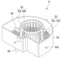
도 4는 본 발명의 실시예에 따른 정수기에 장착되는 냉수 생성 유닛의 외관 사시도.
도 5는 상기 냉수 생성 유닛의 분해 사시도.
도 6은 본 발명의 실시예에 따른 냉수 생성부를 구성하는 구획 부재의 상면 사시도.
도 7은 상기 구획 부재의 저면 사시도.
도 8은 도 6의 8-8을 따라 절개되는 구획 부재의 종단면도.
도 9는 본 발명의 다른 실시예에 따른 구획 부재의 사시도.
도 10은 본 발명의 실시예에 따른 냉수 생성부를 구성하는 냉각수 탱크의 사시도.
도 11은 상기 냉각수 탱크의 내부를 보여주는 사시도.
도 12는 도 4의 12-12를 따라 절개되는 종단면도.
도 13은 도 4의 13-13을 따라 절개되는 종단면도.
도 14는 도 12의 14-14를 따라 절개되는 횡단면도.1 is a front perspective view of a water purifier according to an embodiment of the present invention;
2 is a rear perspective view of the water purifier;
3 is an exploded perspective view showing an internal configuration of a water purifier according to an embodiment of the present invention;
4 is an external perspective view of a cold water generating unit mounted in a water purifier according to an embodiment of the present invention;
5 is an exploded perspective view of the cold water generating unit;
6 is a top perspective view of a partition member constituting a cold water generating unit according to an embodiment of the present invention;
Fig. 7 is a bottom perspective view of the partition member;
Fig. 8 is a longitudinal cross-sectional view of the partition member taken along 8-8 in Fig. 6;
9 is a perspective view of a partition member according to another embodiment of the present invention;
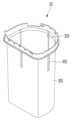
10 is a perspective view of a cooling water tank constituting a cold water generating unit according to an embodiment of the present invention;
11 is a perspective view showing the inside of the cooling water tank;
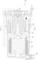
12 is a longitudinal cross-sectional view taken along 12-12 of FIG. 4;
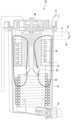
13 is a longitudinal cross-sectional view taken along 13-13 of FIG. 4;
Fig. 14 is a cross-sectional view taken along 14-14 of Fig. 12;
이하에서는 본 발명의 실시예에 따른 정수기에 대하여 도면을 참조하여 상세히 설명한다.Hereinafter, a water purifier according to an embodiment of the present invention will be described in detail with reference to the drawings.
도 1은 본 발명의 실시예에 따른 정수기의 전면 사시도이고, 도 2는 상기 정수기의 배면 사시도이다.1 is a front perspective view of a water purifier according to an embodiment of the present invention, and FIG. 2 is a rear perspective view of the water purifier.
도 1 및 도 2를 참조하면, 본 발명의 실시예에 따른 정수기(10)는, 외부 급수원으로부터 직접 공급되는 물을 냉각 또는 가열시켜 취출하는 직수형 냉온 정수기이다.Referring to FIGS. 1 and 2 , a
상세히, 상기 정수기(10)는, 바닥부를 이루는 베이스(11)와, 상기 베이스(11)의 상면 가장자리에 놓이는 하우징(12)과, 상기 하우징(12)의 개구된 상면을 덮는 커버(13)와, 상기 커버(13)의 상면에 형성되는 컨트롤 패널(14) 및 상기 하우징(12)의 외주면으로부터 돌출되는 워터 슈트(water chute)(15) 중 적어도 일부 또는 전부를 포함할 수 있다.In detail, the
더욱 상세히, 상기 워터 슈트(15)가 형성되는 부분이 상기 정수기(10)의 전면으로 정의되고, 그 반대면이 배면으로 정의될 수 있다. 그리고, 상기 하우징(12)의 배면 하단에는 토출 그릴(122)이 형성되어, 후술하게 될 응축기와 열교환된 공기가 상기 하우징(12) 외부로 배출된다.In more detail, the part where the
또한, 상기 컨트롤 패널(14)은 상기 정수기(10)의 전단부 쪽에 가까운 위치에 형성될 수 있으며, 설계 조건에 따라 상기 정수기(10)의 상면 중앙부 또는 후단부 쪽에 가까운 위치에 형성될 수도 있다. 그리고, 상기 컨트롤 패널(14)은 상기 워터 슈트(15)의 전방에 위치한 사용자의 눈에 쉽게 인지되도록 후방으로 갈수록 높아지는 형태로 경사지게 형성될 수 있다.In addition, the
상세히, 상기 컨트롤 패널(14)은 상기 정수기(10)의 상면으로부터 후단부가 전단부보다 높게 돌출되는 패널 본체(141)와, 상기 패널 본체(141)의 상면을 덮는 패널 커버(142)를 포함할 수 있다. 그리고, 도 3에 도시된 바와 같이, 상기 패널 본체(141)에는 다수의 버튼부들이 장착되기 위한 홀 또는 홈들이 형성될 수 있고, 상기 홀 또는 홈들에 버튼들이 각각 장착될 수 있다. 그리고, 상기 패널 커버(142)에는 상기 버튼들에 대응하는 버튼 메뉴들이 인쇄될 수 있다.In detail, the
상기 컨트롤 패널(14)에 구비되는 버튼은, 파워 버튼과, 물 취출 버튼과, 취출되는 물의 종류를 선택하기 위한 버튼과, 물의 온도를 설정하기 위한 버튼, 및 물의 취출량을 설정하기 위한 버튼 등을 포함할 수 있다. 그리고, 상기 패널 커버(142)에는 상기 버튼들을 표시하는 그림 또는 문자 정보가 인쇄될 수 있다. 상기 취출되는 물의 종류는, 정수,냉수,온수,미네랄수를 포함할 수 있다.The buttons provided on the
또한, 상기 워터 슈트(15)는 상기 정수기(10)의 전단부 중심과 후단부 중심을 잇는 선을 따라서 상기 정수기(10)의 전방으로 소정 길이 연장될 수 있고, 상기 정수기(10)의 전단부 중심에서 좌우측으로 각각 90도 범위 내에서 회전 가능하게 장착될 수 있다. 즉, 상기 워터 슈트(15)는 총 180도 회전 가능하다.In addition, the
또한, 상기 워터 슈트(15)가 회전 가능하도록 상기 워터 슈트(15)의 후단에는 원형의 띠 형상으로 이루어지는 회전 가이드(16)가 장착될 수 있다. 상기 워터 슈트(15)와 상기 회전 가이드(16)는 한 몸으로 사출 성형될 수도 있고, 별도의 부품으로 이루어져 체결부재에 의하여 한 몸으로 결합되는 것도 가능하다.In addition, a
또한, 상기 하우징(12)의 전면에는 상기 워터 슈트(15)의 회전을 가이드하는 가이드 홀(121)이 형성될 수 있고, 상기 워터 슈트(15)는 상기 가이드 홀(121)을 따라 좌측 및 우측으로 90도씩 회전 가능하다.In addition, a
또한, 상기 워터 슈트(15)의 저면에는 물 취출을 위한 취출구(151)가 형성된다. 상기 취출구(151)는 하나 또는 복수 개가 형성될 수 있으며, 취출구(151)가 한 개일 경우에는 단일의 취출구를 통하여 냉수,정수,온수가 토출되도록 유로를 형성할 수 있다. 반면, 도시되지는 않았으나, 다수 개의 취출구(151)가 전후 방향으로 일렬 배치되어, 냉수,정수,온수가 별개의 취출구로 취출되도록 할 수도 있다.In addition, an
또한, 상기 워터 슈트(15)의 저면에는 센서(152)가 장착되어, 사용자가 컵과 같은 저장 용기를 상기 워터 슈트(15) 하측에 위치시키면 물이 취출되도록 할 수 있다. 그러면, 상기 컨트롤 패널(14)에 구비된 물취출 버튼을 눌러서 물취출 명령을 입력하더라도, 컵이 워터 슈트(15)의 하측에 위치하기 전에 상기 취출구(151)로부터 물이 취출되는 것을 방지할 수 있다.In addition, a
도 3은 본 발명의 실시예에 따른 정수기의 내부 구성을 보여주는 분해 사시도이다.3 is an exploded perspective view showing an internal configuration of a water purifier according to an embodiment of the present invention.
도 3을 참조하면, 본 발명의 실시예에 따른 정수기(10)의 외형을 이루는 상기 하우징(12)의 내부에는, 물을 냉각하기 위한 냉매 사이클과, 냉수 생성을 위한 냉수 생성 유닛(30)을 포함하는 다수의 구성 요소들이 수용된다.Referring to FIG. 3 , a refrigerant cycle for cooling water and a cold
상세히, 상기 정수기(10)는, 상기 베이스(11)의 상면 일측에 놓여서 냉매를 고온 고압의 기상 냉매로 압축하는 압축기(18)와, 상기 베이스(11)의 후측에 놓여서 상기 압축기(18)로부터 토출되는 냉매를 고온 고압의 액상 냉매로 응축시키는 응축기(19)와, 상기 정수기(10)가 놓이는 실내의 공기를 흡입하여 상기 응축기(19)와 열교환하도록 하는 응축팬(191) 중 적어도 일부 또는 전부를 포함할 수 있다.In detail, the
또한, 상기 정수기(10)는, 급수원으로부터 공급되는 물에 포함된 이물질을 걸러주는 필터 어셈블리(17)를 더 포함할 수 있다. 상기 필터 어셈블리(17)는 상기 베이스(11)의 전단부 쪽에 위치할 수 있다. 그리고, 상기 필터 어셈블리(17)는 프리 카본 필터(pre carbon filter)와 중공사막 필터(Ultra Filtration filter) 중 어느 하나 또는 모두를 포함할 수 있다.In addition, the
또한, 상기 정수기(10)는, 상기 응축기(19)로부터 토출되는 냉매를 저온 저압의 2상 냉매로 팽창시키는 팽창변(미도시)과, 상기 팽창변을 통과한 저온 저압의 2상 냉매가 흐르는 증발기(후술함)를 더 포함할 수 있다.In addition, the
상세히, 상기 정수기(10)는 상기 증발기 및 냉수가 흐르는 냉수 배관(후술함)을 포함하는 냉수 생성 유닛(30)을 더 포함할 수 있고, 상기 냉수 생성 유닛(30)은 상기 응축기(19)의 상측에 놓일 수 있으나, 이에 제한되지는 않는다.In detail, the
또한, 상기 정수기(10)는 상기 응축기를 감싸는 가이드 덕트(20)와, 상기 냉수 생성 유닛(30)의 저면을 지지하는 탱크 지지부(21)를 더 포함할 수 있다. 그리고, 상기 탱크 지지부(21)와 상기 가이드 덕트(20)는 한 몸으로 플라스틱 사출 성형되거나, 별도의 물품으로 제공되어 체결 부재에 의하여 한 몸으로 결합될 수도 있다.In addition, the
또한, 상기 정수기(10)는 급수되는 물을 설정 온도로 가열하기 위한 온수 히터(22)를 더 포함할 수 있다. 그리고, 상기 필터(17)의 출구측에 연결되는 워터 파이프로부터 상기 온수 히터(22) 쪽으로 연장되는 온수 유로와 상기 냉수 생성 유닛(30) 쪽으로 연장되는 냉수 유로가 각각 분지될 수 있다. 따라서, 온수 취출 명령이 입력되면 상기 혼수 히터(22)를 통과한 물이 취출되고, 냉수 취출 명령이 입력되면 상기 냉수 생성 유닛(30)을 통과한 물이 취출된다. 그리고, 상온의 정수 취출 명령이 입력되면, 상기 필터(17)의 출구에서 연장되는 워터 배관을 따라 흐르는 물이 취출된다.In addition, the
도 4는 본 발명의 실시예에 따른 정수기에 장착되는 냉수 생성 유닛의 외관 사시도이고, 도 5는 상기 냉수 생성 유닛의 분해 사시도이다.4 is an external perspective view of a cold water generating unit mounted in a water purifier according to an embodiment of the present invention, and FIG. 5 is an exploded perspective view of the cold water generating unit.
도 4 및 도 5를 참조하면, 본 발명의 실시예에 따른 냉수 생성 유닛(30)은, 냉각수가 채워지는 냉각수 탱크(33)와, 상기 냉각수 탱크(33)를 수용하여 상기 냉각수 탱크(33)가 실내 공기로부터 단열되도록 하는 단열 케이스(31)와, 상기 단열 케이스(31)를 관통하여 상기 냉각수 탱크(33)의 내부 공간과 연통하는 냉각수 밸브(32)와, 상기 냉각수 탱크(33) 내부에 수용되는 냉수 배관(34)과, 상기 냉수 배관(34)의 상측에 놓여서 상기 냉각수 탱크(33)의 내부 공간을 상측과 하측 공간(또는 제 1 공간과 제 2 공간)으로 구획하는 구획 부재(35)와, 상기 구획 부재(35)에 안착되는 증발기(36)와, 상기 냉각수 탱크(33)의 상면을 덮는 탱크 커버(37)와, 상기 탱크 커버(37)의 내측에 고정되고, 회전축이 상기 냉각수 탱크(33)의 바닥 쪽을 향하여 연장되는 교반 모터(38)와, 상기 냉각수 탱크(33) 내부에 수용되고 상기 교반 모터(38)의 회전축에 연결되는 교반 부재(39), 및 상기 탱크 커버(37)를 덮어서 상기 단열 케이스(31)의 상면에 안착되는 단열 커버(40)를 포함할 수 있다. 상기 교반 부재(39)는 하향 연장되어, 상기 구획 부재(35)의 하측에 정의되는 상기 냉각수 탱크(33)의 하측 공간(제 2 공간)에 놓일 수 있다.Referring to FIGS. 4 and 5 , the cold
상세히, 상기 냉각수 밸브(32)를 통하여 상기 냉각수 탱크(33) 내부로 냉각수를 주입하고, 상기 냉각수 밸브(32)를 개방하여 상기 냉각수 탱크(33)에 채워진 냉각수를 배수시킬 수 있다. 즉, 상기 냉각수 밸브(32)는 냉각수 공급과 냉각수 배출 기능을 겸하는 밸브일 수 있다. 다른 방법으로서, 상기 냉각수 밸브(32)는 드레인 밸브의 기능만 수행하고, 상기 탱크 커버(37)에 냉각수 주입 포트 또는 냉각수 주입 밸브가 장착되는 구조도 가능하다.In detail, cooling water may be injected into the cooling
한편, 상기 단열 케이스(31)의 내주면에는 다수의 장착 가이드홈들(311)이 수직 방향으로 소정 길이 형성될 수 있다. 그리고, 상기 다수의 장착 가이드홈들(311)은 상기 단열 케이스(31)의 원주 방향으로 이격 배치될 수 있다.Meanwhile, a plurality of mounting
상기 단열 케이스(31) 내부에 상기 냉각수 탱크(33)가 수용되고, 상기 냉각수 탱크(33)의 내부에 상기 냉수 배관(34)이 수용된다. 그리고, 상기 구획 부재(35)가 상기 냉각수 탱크(33) 내부에 수용되어, 상기 냉각수 탱크(33)의 내부 공간을 상측 공간과 하측 공간으로 구획한다.The cooling
또한, 상기 구획 부재(35)의 내측에 상기 증발기(36)가 안착되고, 상기 증발기(36)가 수용되는 공간에 얼음이 생성된다. 상기 탱크 커버(37)가 상기 냉각수 탱크(33)의 상면에 안착되면, 상기 교반 모터(38)의 회전축에 연결된 상기 교반 부재(39)는 상기 구획 부재(35)를 통과하여 상기 냉수 배관(34)이 수용된 공간으로 인입된다. 그리고, 상기 단열 커버(40)는 상기 탱크 커버(37)를 덮어서 상기 단열 케이스(31) 상면에 안착되면, 상기 냉각수 탱크(33)가 상기 단열 케이스(31) 외부로부터 단열된다.In addition, the
이하에서는 상기 구획 부재(35)의 구조 및 기능에 대하여 도면을 참조하여 상세히 설명한다.Hereinafter, the structure and function of the
도 6은 본 발명의 실시예에 따른 냉수 생성부를 구성하는 구획 부재의 상면 사시도이고, 도 7은 상기 구획 부재의 저면 사시도이며, 도 8은 도 6의 8-8을 따라 절개되는 구획 부재의 종단면도이다.6 is a top perspective view of a partition member constituting a cold water generating unit according to an embodiment of the present invention, FIG. 7 is a bottom perspective view of the partition member, and FIG. 8 is a longitudinal cross-sectional view of the partition member cut along 8-8 in FIG. It is also
도 6 내지 도 8을 참조하면, 본 발명의 실시예에 따른 구획 부재(35)는, 바닥부(351)와, 상기 바닥부(351)의 외측 가장자리에서 상측으로 연장되는 외벽부(352), 및 상기 바닥부(351)의 중앙에서 상측으로 연장되는 내벽부(353)를 포함할 수 있다.6 to 8, the
상세히, 상기 바닥부(351)는, 가로 방향과 세로 방향으로 교차하여 연장되는 다수의 격자 리브(351a)와, 상기 격자 리브들(351a) 사이에 형성되는 냉각수 통과할(351b)로 이루어진다. 따라서, 냉각수가 상기 냉각수 통과홀(351b)을 통하여 상기 바닥부(351)의 상측과 하측 공간을 왕래할 수 있다.In detail, the
또한, 상기 바닥부(351)의 내측에는 원형의 홀이 형성될 수 있고, 상기 내벽부(353)는 상기 원형의 홀 가장자리에서 상측으로 연장 형성된다. 상세히, 상기 내벽부(353)는, 상기 원형의 홀 가장자리에서 상측으로 연장되는 다수의 버티컬 리브(353a)와, 상기 다수의 버티컬 리브들(353a)을 연결하는 원형의 띠 형상의 어퍼 리브(353b)를 포함할 수 있다. 상기 바닥부(351)의 내측에 형성되는 홀은 교반 부재 통과홀로 정의될 수 있고, 상기 홀은 원형 뿐만 아니라 다각형 형상으로 이루어질 수도 있다. 그러면, 상기 내벽부 또는 단면이 원형 또는 다각형인 통 형상으로 이루어질 것이다.In addition, a circular hole may be formed inside the
더욱 상세히, 상기 다수의 버티컬 리브들(353a)은 상기 원형의 홀의 원주 방향으로 일정 간격 이격 배치되어 원통 형상을 이룰 수 있다. 또는, 상기 다수의 버티컬 리브들(353a)이 경사지게 연장되어, 상측으로 갈수록 직경이 작아지는 단면을 가지는 잘려진 원뿔 형상(truncated cone)을 이룰 수 있다. 그리고, 상기 어퍼 리브(353b)와 같은 원 형의 띠 형상을 이루는 다수의 리브들이 상하 방향으로 이격 배치되도록 하여, 상기 내벽부(353)도 격자 모양으로 이루어지도록 할 수 있다.In more detail, the plurality of
상기 외벽부(352)는 상기 바닥부(351) 또는 상기 내벽부(353)와 달리 냉각수 또는 공기가 통과할 수 있는 홀이 없는 차폐벽으로 구성된다. 즉, 상기 외벽부(352)를 기준으로 상기 구획 부재(35)의 내측 공간과 외측 공간이 구획된다.Unlike the
상기 외벽부(352)의 외주면에는 다수의 장착 가이드(355)가 돌출 형성될 수 있다. 상세히, 상기 다수의 장착 가이드(355)는 짝수 개가 제공되어 서로 마주보는 위치에 형성될 수도 있고, 홀수 개가 서로 동일한 거리를 형성하는 지점에 형성될 수도 있다. 그러나, 상기 장착 가이드(355)의 형성 위치와 개수는 제시되는 실시예에 제한되지 아니함을 밝혀둔다.A plurality of mounting
그리고, 상기 장착 가이드(355)는, 상기 외벽부(352)의 외주면으로부터 돌출되는 이격 리브(355a)와, 상기 이격 리브(355a)의 단부에서 더 연장되는 고정 리브(355b)를 포함할 수 있다.The mounting
상기 이격 리브(355a)는 상기 외벽부(352)의 외주면으로부터 수평 방향으로 소정 길이 돌출되고, 상기 외벽부(352)의 상단에서 하단까지 연장될 수 있다. 상기 구획 부재(35)가 상기 냉각수 탱크(33)의 내부에 장착되면, 상기 이격 리브(355a)의 단부는 상기 냉각수 탱크(33)의 내주면에 접촉된다. 따라서, 상기 외벽부(352)는 상기 냉각수 탱크(33)의 내주면으로부터 상기 이격 리브(355a)의 돌출 길이만큼 이격된다.The
그리고, 상기 고정 리브(355b)는 상기 냉각수 탱크(33)의 내벽에 삽입되어, 사기 구획 부재(355)가 상기 냉각수 탱크(33)의 대략 중간 부분에 고정되도록 한다.Also, the fixing
또한, 상기 외벽부(352)의 어느 일측에는 단차부(352a)가 형성될 수 있다. 상기 단차부(352a)는 상기 외벽부(352)의 일부가 상기 내벽부(353) 쪽으로 함몰되거나 단차져서 형성된다.In addition, a stepped
따라서, 상기 구획 부재(35)가 상기 냉각수 탱크(33) 내부에 장착되면, 상기 단차부(352a)를 정의하는 상기 외벽부(352) 부분과 상기 냉각수 탱크(33)의 내벽 사이에는 빈 공간이 형성되고, 상기 빈 공간에 상기 냉수 배관(34)의 유입 단부와 토출 단부가 배치된다.Therefore, when the
상기 단차부(352a)에 의하여 상기 냉수 배관(34)의 유입 단부와 토출 단부가 상기 구획 부재(35)로부터 이격됨으로써, 상기 구획 부재(35) 내부에 생성되는 얼음이 상기 냉수 배관(34)의 유입 단부와 토출 단부에 접촉하는 것을 방지할 수 있다. 그 결과, 상기 냉수 배관(34)을 따라 흐르는 냉수가 결빙되는 것을 방지할 수 있다.Since the inlet end and the discharge end of the
한편, 상기 외벽부(352)와 상기 내벽부(353) 및 상기 바닥부(351)에 의하여 형성되는 공간은 증발기 수용부(357) 또는 얼음 생성 공간으로 정의될 수 있다.Meanwhile, a space formed by the
상기 바닥부(351)에는 다수의 증발기 지지 리브들(354)이 단차지는 계단 형태로 형성되어, 상기 증발기(36)의 하단부를 지지하도록 할 수 있다. 상기 증발기 지지 리브들(354) 각각이 도시된 바와 같은 단차지는 계단 형태로 이루어짐으로써, 상기 증발기(36)가 상기 내벽부(353)와 상기 바닥부(351)로부터 이격되는 상태로 상기 구획 부재(35) 내부에 장착될 수 있다.A plurality of
그리고, 상기 압축기(18)가 구동하여 냉동 사이클의 운전이 이루어지면, 상기 증발기(36)를 통과하는 냉매와 상기 냉각수 탱크(33)에 저장된 냉각수가 열교환하여, 상기 증발기(36) 표면에 얼음이 생성된다. 그리고, 상기 증발기(36) 표면에 생성되는 얼음이 성장하여 상기 증발기 수용부(357)를 채울 수 있다.When the
상기 증발기(36)는, 도시된 바와 같이 스파이럴 형상으로 감겨서 원통 형상을 이루어지므로, 생성되는 얼음도 원통형의 튜브 형상으로 이루어질 수 있다. 여기서, 상기 증발기 수용부(357) 내부에 생성된 얼음이 성장하여 부피가 커지더라도, 상기 외벽부(352)에 의하여 얼음의 가로 방향 성장이 제한된다. 그리고, 상기 외벽부(352)가 상기 냉각수 탱크(33)의 내주면으로부터 이격되므로, 얼음이 성장하는 과정에서 상기 냉각수 탱크(33)의 내주면에 직접 접촉하는 현상은 발생하지 않는다. 따라서, 상기 구획 부재(35)의 위치에 대응하는 상기 냉각수 탱크(33)의 표면이 과도하게 냉각되지 않으므로 상기 단열 케이스(31)의 외면에 이슬이 맺히는 현상을 방지할 수 있는 장점이 있다. 이러한 이유 때문에, 상기 외벽부(352)는, 다수의 개구부가 형성되는 상기 내벽부(353) 또는 바닥부(351)와 달리, 냉각수가 통과할 수 있는 홀이나 슬릿이 없는 연속면으로 이루어진다. 즉, 상기 외벽부(352)는 가로 방향으로 얼음이 성장하여 상기 냉각수 탱크(33)의 내벽에 접촉하는 것을 차단하는 차단벽으로서 기능한다.Since the
한편, 상기 바닥부(351)의 저면에는 다수의 냉수 배관 지지 리브(356)가 연장될 수 있고, 상기 다수의 냉수 배관 지지 리브들(356)은 상기 다수의 증발기 지지리브(354)가 형성되는 직하방에서 연장될 수 있다. 그러나, 반드시 이에 제한되는 것은 아니며, 인접하는 증발기 지지 리브들(354) 사이에 해당하는 지점에 형성될 수도 있다.Meanwhile, a plurality of cold water
도 9는 본 발명의 다른 실시예에 따른 구획 부재의 사시도이다.9 is a perspective view of a partition member according to another embodiment of the present invention.
도 9를 참조하면, 본 실시예에 따른 구획 부재(35)는, 도 6 내지 도 8에 제시되는 구획 부재(35)와 구성이 동일하되, 상기 장착 가이드(355)의 형태만 다르다.Referring to FIG. 9 , the
즉, 상기 외벽부(352)의 외주면에는 상기 고정 리브(355b)만 돌출되고, 상기 이격 리브(355a) 부분은 제거될 수 있다. 상기 이격 리브(355a)가 제거됨으로써, 상기 외벽부(352)와 상기 냉각수 탱크(33) 사이의 공간이 상기 이격 리브(355a)에 의하여 구획되지 않는다.That is, only the fixing
도 10은 본 발명의 실시예에 따른 냉수 생성부를 구성하는 냉각수 탱크의 사시도이고, 도 11은 상기 냉각수 탱크의 내부를 보여주는 사시도이다.10 is a perspective view of a cooling water tank constituting a cold water generator according to an embodiment of the present invention, and FIG. 11 is a perspective view showing the inside of the cooling water tank.
도 10 및 도 11을 참조하면, 본 발명의 실시예에 따른 냉각수 탱크(33)는, 탱크 바디(331)와, 상기 탱크 바디(331)의 외면으로부터 돌출되고, 하측으로 소정 길이 연장되는 가이드 돌기(332)와, 상기 탱크 바디(331)의 바닥에서 돌출되어 상기 냉수 배관(34)의 저면을 지지하는 다수의 냉수 배관 지지 리브들(334), 및 상기 냉각수 밸브(32)를 수용하기 위하여 상기 탱크 바디(331)의 바닥으로부터 융기되는 냉각수 밸브 수용부(335)를 포함할 수 있다.10 and 11 , the
상기 가이드 돌기(332)는 다수 회 절곡되는 형태로 이루어져, 상기 탱크 바디(331)의 내주면에 끼움홈(333)을 형성한다. 그리고, 상기 끼움홈(333)에는 상기 장착 가이드(355)를 구성하는 고정 리브(355b)가 삽입된다. 그리고, 상기 가이드 돌기(332)는 상기 단열 케이스(3)의 내주면에 형성된 장착 가이드홈(311)에 끼워질 수 있다.The
상기 구획 부재(35)가 상기 냉각수 탱크(33) 내부에 장착되면, 상기 고정 리브(355b)가 상기 끼움홈(333)을 따라 하강하다가 상기 끼움홈(333)의 하단부에 걸리게 된다. 그러면, 상기 구획 부재(35)는 상기 냉각수 탱크(33)의 바닥부로부터 상측으로 소정 길이 이격된 지점에서 고정되어, 상기 냉각수 탱크(33)의 내부 공간이 상기 구획 부재(35)의 바닥부(351)를 기준으로 상측 공간(제 1 공간)과 하측 공간(제2공간)으로 구획된다. 다만, 상기 냉각수 탱크(33)에 저장된 냉각수는 상기 바닥부(351)의 냉수 통과홀들(351b)을 통하여 상기 상측 공간과 하측 공간을 자유로이 왕래할 수 있다.When the
도 12는 도 4의 12-12를 따라 절개되는 종단면도이고, 도 13은 도 4의 13-13을 따라 절개되는 종단면도이며, 도 14는 도 12의 14-14를 따라 절개되는 횡단면도이다. 참고로, 도 12 및 13에 보이는 단면도는 상기 단열 케이스(31)와 단열 커버(40)가 제거된 상태의 종단면도이다.12 is a longitudinal cross-sectional view taken along 12-12 in FIG. 4, FIG. 13 is a longitudinal cross-sectional view taken along 13-13 in FIG. 4, and FIG. 14 is a cross-sectional view taken along 14-14 in FIG. For reference, the cross-sectional views shown in FIGS. 12 and 13 are longitudinal cross-sectional views in a state where the
도 12 내지 도 14를 참조하면, 상기 냉수 생성 유닛(30)의 조립이 완료되면, 상기 구획 부재(35)를 구성하는 상기 외벽부(352)의 상면은 상기 내벽부(353)의 상면보다 낮게 형성된다.12 to 14, when the assembly of the cold
상세히, 냉각수의 수위(w)는, 상기 외벽부(352)의 상면을 지나는 수평면(a2)보다 높고, 상기 내벽부(353)의 상면을 지나는 수평면(a1)보다 낮게 형성되도록 한다. 그러면, 상기 교반 부재(39)가 회전할 때, 도 13의 화살표로 표시된 바와 같이, 상기 냉수 배관(34)이 수용되는 상기 하측 공간의 냉각수가 상기 외벽부(352)와 상기 냉각수 탱크(33) 사이에 형성되는 통로를 따라 상승한다. 그리고, 상승하는 냉각수는 상기 외벽부(352)를 타고 넘어서 상기 상측 공간, 즉 상기 증발기 수용부(357)로 낙하하고, 상기 증발기 수용부(357)로 낙하하는 냉각수는 상기 내벽부(353)를 통과하여 상기 하측 공간으로 되돌아간다.In detail, the water level w of the cooling water is higher than the horizontal plane a2 passing through the upper surface of the
만일, 냉각수 수위(w)가 상기 외벽부(352)의 상면보다 낮으면, 상기 외벽부(352)에 의하여 냉각수의 유동이 이루어지지 못하는 문제점이 발생할 수 있다.If the cooling water level (w) is lower than the upper surface of the
또한, 상기 냉각수의 수위(w)는 상기 내벽부(353)의 상면보다 낮게 형성되는 것이 좋다. 만일, 상기 냉각수의 수위(w)가 상기 내벽부(353)의 상면과 동일하거나 더 높게 형성되면, 상기 증발기 표면에 생성되는 얼음(i)이 상기 내벽부(353)의 상단부까지 성장하여, 냉각수의 순환을 방해할 수 있다.In addition, it is preferable that the water level (w) of the cooling water is formed lower than the upper surface of the
이러한 이유들 때문에, 상기 내벽부(353)의 상면은 상기 외벽부(352)의 상면보다 소정 길이(a) 더 높게 형성되고, 냉각수는 상기 내벽부(353)의 상면과 외벽부(352)의 상면에 형성되도록 하는 것이 좋다.For these reasons, the upper surface of the
도 14를 참조하면, 상기 장착 가이드(355)의 가로 방향 길이(d)는, 상기 이격 리브(353a)의 길이(d1)과 상기 고정 리브(353b)의 길이(d2)의 합으로 정의될 수 있다. 그리고, 상기 외벽부(352)와 냉각수 탱크(33)의 측벽 사이에는 이격 공간이 형성되며, 냉각수 상승 공간(S)으로 정의할 수 있다. 그리고, 상기 냉각수 상승 공간(S)의 폭은 상기 이격 리브(353a)의 돌출 길이(d1)에 대응된다.Referring to FIG. 14, the horizontal length (d) of the mounting
이와 같이, 증발기(36)가 장착되는 영역에 외벽부(352)가 형성되고, 상기 외벽부(352)가 냉각수 탱크(33)의 벽면으로부터 이격됨으로써, 상기 증발기(36) 주위에 생성되는 얼음이 상기 냉각수 탱크(33)의 벽면에 직접 접촉하는 현상을 방지할 수 있는 장점이 있다.In this way, the
Claims (12)
Translated fromKorean상기 냉각수 탱크의 내부에 장착되어, 상기 냉각수 탱크의 내부 공간을 상측 공간과 하측 공간으로 구획하는 구획 부재;
상기 하측 공간에 수용되며, 음용수가 흐르는 냉수 배관;
상기 상측 공간에 수용되며, 냉매가 흐르는 증발기; 및
상기 구획 부재를 관통하여 상기 하측 공간에 놓여서, 상기 냉각수를 교반하는 교반기;를 포함하고,
상기 구획 부재는,
상기 증발기가 안착되고, 다수의 냉각수 통과홀이 형성되는 바닥부와,
상기 바닥부의 가장자리를 따라 상측으로 연장되어 증발기 수용부를 형성하는 외벽부를 포함하고,
상기 외벽부는, 상기 증발기 수용부에서 생성되는 얼음이 상기 냉각수 탱크의 내벽에 접촉하는 것을 차단하도록, 상기 냉각수 탱크의 내벽으로부터 이격되는 것을 특징으로 하는 정수기.a coolant tank in which coolant is stored;
a partition member mounted inside the cooling water tank to divide the inner space of the cooling water tank into an upper space and a lower space;
a cold water pipe accommodated in the lower space and through which drinking water flows;
an evaporator accommodated in the upper space and through which refrigerant flows; and
An agitator passing through the partition member and placed in the lower space to agitate the cooling water;
The partitioning member,
A bottom portion in which the evaporator is seated and a plurality of cooling water passage holes are formed;
An outer wall portion extending upward along an edge of the bottom portion to form an evaporator receiving portion,
The outer wall part is spaced apart from the inner wall of the cooling water tank to prevent ice generated in the evaporator accommodating part from contacting the inner wall of the cooling water tank.
상기 외벽부가 상기 냉각수 탱크의 내벽으로부터 이격되도록, 상기 외벽부의 외주면에서 연장되어, 상기 냉각수 탱크의 내벽에 고정되는 장착 가이드를 더 포함하는 정수기.According to claim 1,
and a mounting guide extending from an outer circumferential surface of the outer wall portion and fixed to an inner wall of the cooling water tank so that the outer wall portion is spaced apart from the inner wall of the cooling water tank.
상기 장착 가이드는,
상기 외벽부로부터 연장되는 고정 리브를 포함하고,
상기 냉각수 탱크의 내벽에는 상기 고정 리브가 삽입되는 끼움홈이 형성되는 것을 특징으로 하는 정수기.According to claim 2,
The installation guide,
Including a fixing rib extending from the outer wall portion,
The water purifier, characterized in that the inner wall of the cooling water tank is formed with a fitting groove into which the fixing rib is inserted.
상기 장착 가이드는,
상기 외벽부로부터 연장되어 상기 냉각수 탱크의 내벽에 접촉하는 이격 리브와,
상기 이격 리브의 단부에서 더 연장되는 고정 리브를 포함하고,
상기 냉각수 탱크의 내벽에는 상기 고정 리브가 삽입되는 끼움홈이 형성되는 것을 특징으로 하는 정수기.According to claim 2,
The installation guide,
a separation rib extending from the outer wall portion and contacting the inner wall of the cooling water tank;
And a fixing rib extending further from the end of the separation rib,
The water purifier, characterized in that the inner wall of the cooling water tank is formed with a fitting groove into which the fixing rib is inserted.
상기 끼움홈은, 상기 냉각수 탱크의 일부분이 다수회 절곡되거나 라운드져서 상기 냉각수 탱크의 외벽으로부터 돌출되는 가이드 돌기에 의하여 정의되는 것을 특징으로 하는 정수기.According to claim 3 or 4,
The fitting groove is defined by a guide protrusion protruding from an outer wall of the cooling water tank by bending or rounding a portion of the cooling water tank multiple times.
상기 끼움홈과 상기 가이드 돌기는, 상기 냉각수 탱크의 상단으로부터 하측으로 소정 길이 연장되고,
상기 구획 부재가 상기 냉각수 탱크의 내부에 장착되면, 상기 고정 리브는 상기 끼움홈의 하단에 걸리는 것을 특징으로 하는 정수기.According to claim 5,
The fitting groove and the guide protrusion extend a predetermined length downward from an upper end of the cooling water tank,
The water purifier, characterized in that, when the partition member is mounted inside the cooling water tank, the fixing rib is caught at a lower end of the fitting groove.
상기 냉각수 탱크를 수용하는 단열 케이스를 더 포함하고,
상기 단열 케이스의 내벽에는 상기 가이드 돌기가 삽입되는 장착 가이드 홈이 함몰 형성되는 것을 특징으로 하는 정수기.According to claim 5,
Further comprising an insulating case accommodating the cooling water tank,
The water purifier, characterized in that a mounting guide groove into which the guide protrusion is inserted is recessed on an inner wall of the insulation case.
상기 외벽부의 어느 지점에는, 상기 냉수 배관의 유입 단부 및 토출 단부가 통과하는 공간을 형성하기 위한 단차부가 형성되는 것을 특징으로 하는 정수기.According to claim 1,
A water purifier, characterized in that, at a certain point of the outer wall portion, a stepped portion is formed to form a space through which the inlet end and the discharge end of the cold water pipe pass.
상기 구획 부재는,
상기 바닥부의 내측에 형성되는 교반 부재 통과홀의 가장자리에서 상측으로 연장되는 내벽부를 더 포함하고,
상기 내벽부의 상단은 상기 외벽부의 상단보다 높게 형성되는 것을 특징으로 하는 정수기.According to claim 1,
The partitioning member,
Further comprising an inner wall portion extending upward from the edge of the stirring member passage hole formed inside the bottom portion,
The water purifier, characterized in that the upper end of the inner wall portion is formed higher than the upper end of the outer wall portion.
상기 냉각수는, 상기 내벽부의 상단과 상기 외벽부의 상단 사이에 해당하는 높이까지 채워지는 것을 특징으로 하는 정수기.According to claim 9,
The water purifier characterized in that the cooling water is filled up to a height corresponding to an upper end of the inner wall part and an upper end of the outer wall part.
상기 내벽부는,
상기 바닥부로부터 상측으로 연장되고, 상기 교반 부재 통과홀의 원주 방향으로 배치되는 다수의 버티컬 리브와,
상기 다수의 버티컬 리브의 상단에서 상기 다수의 버티컬 리브를 연결하는 어퍼 리브를 포함하는 정수기.According to claim 9,
the inner wall,
A plurality of vertical ribs extending upward from the bottom portion and disposed in a circumferential direction of the stirring member passage hole;
and an upper rib connecting the plurality of vertical ribs at an upper end of the plurality of vertical ribs.
상기 바닥부의 상면에서 상측으로 연장되어, 상기 증발기를 지지하는 다수의 증발기 지지 리브와,
상기 바닥부의 하면에서 하측으로 연장되어 상기 냉수 배관의 상면을 지지하는 다수의 냉수 배관 지지 리브를 더 포함하는 정수기.
According to claim 9,
a plurality of evaporator support ribs extending upward from an upper surface of the bottom portion to support the evaporator;
The water purifier further comprises a plurality of cold water pipe support ribs extending downward from a lower surface of the bottom portion to support an upper surface of the cold water pipe.
Priority Applications (5)
| Application Number | Priority Date | Filing Date | Title |
|---|---|---|---|
| KR1020160149553AKR102571263B1 (en) | 2016-11-10 | 2016-11-10 | Water purifying apparatus |
| US16/349,102US10882727B2 (en) | 2016-11-10 | 2017-11-10 | Water purifier |
| PCT/KR2017/012746WO2018088849A1 (en) | 2016-11-10 | 2017-11-10 | Water purifier |
| EP17868983.2AEP3540346B1 (en) | 2016-11-10 | 2017-11-10 | Water purifier |
| CN201780068632.3ACN109923359B (en) | 2016-11-10 | 2017-11-10 | Water purifier |
Applications Claiming Priority (1)
| Application Number | Priority Date | Filing Date | Title |
|---|---|---|---|
| KR1020160149553AKR102571263B1 (en) | 2016-11-10 | 2016-11-10 | Water purifying apparatus |
Publications (2)
| Publication Number | Publication Date |
|---|---|
| KR20180052348A KR20180052348A (en) | 2018-05-18 |
| KR102571263B1true KR102571263B1 (en) | 2023-08-25 |
Family
ID=62110638
Family Applications (1)
| Application Number | Title | Priority Date | Filing Date |
|---|---|---|---|
| KR1020160149553AActiveKR102571263B1 (en) | 2016-11-10 | 2016-11-10 | Water purifying apparatus |
Country Status (5)
| Country | Link |
|---|---|
| US (1) | US10882727B2 (en) |
| EP (1) | EP3540346B1 (en) |
| KR (1) | KR102571263B1 (en) |
| CN (1) | CN109923359B (en) |
| WO (1) | WO2018088849A1 (en) |
Families Citing this family (17)
| Publication number | Priority date | Publication date | Assignee | Title |
|---|---|---|---|---|
| KR101878555B1 (en)* | 2016-08-23 | 2018-07-13 | 엘지전자 주식회사 | Cooling water agitator and Water purifying apparatus having the same |
| KR102548269B1 (en)* | 2018-02-23 | 2023-06-27 | 엘지전자 주식회사 | Water purifying apparatus |
| KR102128988B1 (en)* | 2018-11-19 | 2020-07-02 | 엘지전자 주식회사 | Water purifier |
| KR102042579B1 (en)* | 2018-11-19 | 2019-11-08 | 엘지전자 주식회사 | Water purifier |
| KR102115616B1 (en)* | 2018-11-19 | 2020-05-27 | 엘지전자 주식회사 | Water purifier |
| MX2021006625A (en)* | 2018-12-05 | 2021-07-07 | Pepsico Inc | NON-ELECTRIC BEVERAGE FOUNTAIN DISPENSERS AND BEVERAGE SYSTEMS. |
| USD948269S1 (en)* | 2019-02-28 | 2022-04-12 | Société des Produits Nestlé S.A. | Beverage dispenser |
| KR102328859B1 (en)* | 2020-06-22 | 2021-11-22 | 엘지전자 주식회사 | Water purifier |
| KR102201040B1 (en)* | 2020-06-22 | 2021-01-11 | 엘지전자 주식회사 | Water purifier |
| US11816730B2 (en) | 2020-07-10 | 2023-11-14 | Charter Communications Operating, Llc | Low-latency trading platform and communications system |
| IT202100019892A1 (en)* | 2021-07-26 | 2021-10-26 | Watnext Ind S R L | Liquid cooling system for home and office use |
| USD1024649S1 (en)* | 2022-07-19 | 2024-04-30 | Instant Brands Holdings Inc. | User interface for a brewing device |
| USD1024648S1 (en)* | 2022-07-19 | 2024-04-30 | Instant Brands Holdings Inc. | User interface for a brewing device |
| USD1024647S1 (en)* | 2022-07-19 | 2024-04-30 | Instant Brands Holdings Inc. | User interface for a brewing device |
| KR20240016115A (en)* | 2022-07-28 | 2024-02-06 | 삼성전자주식회사 | Chiller, water purifier having the chiller and manufacturing method thereof |
| USD1037746S1 (en)* | 2022-12-22 | 2024-08-06 | Starbucks Corporation | Beverage dispenser |
| USD1073220S1 (en) | 2022-12-23 | 2025-04-29 | Starbucks Corporation | Fluid container rinser |
Citations (3)
| Publication number | Priority date | Publication date | Assignee | Title |
|---|---|---|---|---|
| JP3234346B2 (en) | 1993-04-08 | 2001-12-04 | 三洋電機株式会社 | Beverage supply device |
| JP2003192097A (en) | 2001-12-27 | 2003-07-09 | Hoshizaki Electric Co Ltd | Cold drink feed device |
| KR101191420B1 (en)* | 2009-12-10 | 2012-10-16 | 위니아만도 주식회사 | Cooling unit of cool water ionizer and purifier |
Family Cites Families (12)
| Publication number | Priority date | Publication date | Assignee | Title |
|---|---|---|---|---|
| US3605421A (en) | 1970-02-16 | 1971-09-20 | Earnest H Patrick | Cooler |
| GB2059038B (en) | 1979-09-14 | 1984-07-11 | Paxman N E | Refrigerated probes |
| US20040011730A1 (en) | 2002-07-18 | 2004-01-22 | Powell James R. | AVS slurry feed mechanism |
| CN201010534Y (en) | 2007-03-05 | 2008-01-23 | 裴光泰 | Purifier bucket |
| KR20100078802A (en)* | 2008-12-30 | 2010-07-08 | 위니아만도 주식회사 | Ice forming device and control method thereof in cold water ionizer |
| KR102043173B1 (en)* | 2011-09-30 | 2019-11-12 | 웅진코웨이 주식회사 | Ice-storage tank and water cooler having the same |
| CN103479220B (en) | 2012-06-15 | 2016-08-03 | 滁州富达机械电子有限公司 | A kind of water dispenser |
| KR101443984B1 (en) | 2012-12-05 | 2014-09-23 | 주식회사 동양매직 | Water purifier having ice-maker |
| CN203163415U (en) | 2012-12-18 | 2013-08-28 | 奇迪电器集团有限公司 | Water dispenser and refrigeration liner of water dispenser |
| KR102262828B1 (en) | 2014-04-01 | 2021-06-09 | 코웨이 주식회사 | Inner tank and water purifier having ice-maker comprising the same |
| KR20160055471A (en) | 2014-11-10 | 2016-05-18 | 엘지전자 주식회사 | Water purifier |
| CN204434380U (en) | 2014-12-25 | 2015-07-01 | 宁国市老百姓净水家电服务中心 | A kind of family expenses Quick purifying device |
- 2016
- 2016-11-10KRKR1020160149553Apatent/KR102571263B1/enactiveActive
- 2017
- 2017-11-10WOPCT/KR2017/012746patent/WO2018088849A1/ennot_activeCeased
- 2017-11-10USUS16/349,102patent/US10882727B2/enactiveActive
- 2017-11-10CNCN201780068632.3Apatent/CN109923359B/enactiveActive
- 2017-11-10EPEP17868983.2Apatent/EP3540346B1/enactiveActive
Patent Citations (3)
| Publication number | Priority date | Publication date | Assignee | Title |
|---|---|---|---|---|
| JP3234346B2 (en) | 1993-04-08 | 2001-12-04 | 三洋電機株式会社 | Beverage supply device |
| JP2003192097A (en) | 2001-12-27 | 2003-07-09 | Hoshizaki Electric Co Ltd | Cold drink feed device |
| KR101191420B1 (en)* | 2009-12-10 | 2012-10-16 | 위니아만도 주식회사 | Cooling unit of cool water ionizer and purifier |
Also Published As
| Publication number | Publication date |
|---|---|
| US10882727B2 (en) | 2021-01-05 |
| CN109923359B (en) | 2021-06-01 |
| CN109923359A (en) | 2019-06-21 |
| WO2018088849A1 (en) | 2018-05-17 |
| EP3540346A4 (en) | 2020-09-02 |
| EP3540346A1 (en) | 2019-09-18 |
| US20190276299A1 (en) | 2019-09-12 |
| EP3540346B1 (en) | 2022-03-02 |
| KR20180052348A (en) | 2018-05-18 |
Similar Documents
| Publication | Publication Date | Title |
|---|---|---|
| KR102571263B1 (en) | Water purifying apparatus | |
| KR102515589B1 (en) | Water purifying apparatus | |
| CN107625428B (en) | Water purifier | |
| KR101811536B1 (en) | Water purifying apparatus | |
| EP3702703B1 (en) | Refrigerator including ice making device | |
| US9677800B2 (en) | Refrigerator with an ice transfer flow duct | |
| KR102530082B1 (en) | Water purifying apparatus | |
| KR20240166441A (en) | Control method for water purifying apparatus | |
| KR20180022062A (en) | Cooling water agitator and Water purifying apparatus having the same | |
| KR102548269B1 (en) | Water purifying apparatus | |
| KR102500810B1 (en) | Water purifying apparatus | |
| JP5563759B2 (en) | Drinking water dispenser | |
| KR102413202B1 (en) | Water purifying apparatus | |
| JP5308143B2 (en) | Drinking water dispenser | |
| KR100764553B1 (en) | Cold water ice maker | |
| KR102136802B1 (en) | Ice manufacturing apparatus | |
| KR100725497B1 (en) | Kimchi Refrigerator | |
| KR102763000B1 (en) | Method for controlling water purifying apparatus | |
| KR102447436B1 (en) | refrigerator | |
| KR20220162955A (en) | refrigerator |
Legal Events
| Date | Code | Title | Description |
|---|---|---|---|
| PA0109 | Patent application | Patent event code:PA01091R01D Comment text:Patent Application Patent event date:20161110 | |
| PG1501 | Laying open of application | ||
| A201 | Request for examination | ||
| PA0201 | Request for examination | Patent event code:PA02012R01D Patent event date:20211006 Comment text:Request for Examination of Application Patent event code:PA02011R01I Patent event date:20161110 Comment text:Patent Application | |
| E902 | Notification of reason for refusal | ||
| PE0902 | Notice of grounds for rejection | Comment text:Notification of reason for refusal Patent event date:20230321 Patent event code:PE09021S01D | |
| E701 | Decision to grant or registration of patent right | ||
| PE0701 | Decision of registration | Patent event code:PE07011S01D Comment text:Decision to Grant Registration Patent event date:20230601 | |
| GRNT | Written decision to grant | ||
| PR0701 | Registration of establishment | Comment text:Registration of Establishment Patent event date:20230822 Patent event code:PR07011E01D | |
| PR1002 | Payment of registration fee | Payment date:20230823 End annual number:3 Start annual number:1 | |
| PG1601 | Publication of registration |