KR102569539B1 - Object sensing system for vehicle and object sensing method for vehicle - Google Patents
Object sensing system for vehicle and object sensing method for vehicleDownload PDFInfo
- Publication number
- KR102569539B1 KR102569539B1KR1020160147656AKR20160147656AKR102569539B1KR 102569539 B1KR102569539 B1KR 102569539B1KR 1020160147656 AKR1020160147656 AKR 1020160147656AKR 20160147656 AKR20160147656 AKR 20160147656AKR 102569539 B1KR102569539 B1KR 102569539B1
- Authority
- KR
- South Korea
- Prior art keywords
- vehicle
- signal
- driving lane
- control signal
- changed
- Prior art date
- Legal status (The legal status is an assumption and is not a legal conclusion. Google has not performed a legal analysis and makes no representation as to the accuracy of the status listed.)
- Active
Links
Images


Classifications
- G—PHYSICS
- G01—MEASURING; TESTING
- G01S—RADIO DIRECTION-FINDING; RADIO NAVIGATION; DETERMINING DISTANCE OR VELOCITY BY USE OF RADIO WAVES; LOCATING OR PRESENCE-DETECTING BY USE OF THE REFLECTION OR RERADIATION OF RADIO WAVES; ANALOGOUS ARRANGEMENTS USING OTHER WAVES
- G01S7/00—Details of systems according to groups G01S13/00, G01S15/00, G01S17/00
- G01S7/02—Details of systems according to groups G01S13/00, G01S15/00, G01S17/00 of systems according to group G01S13/00
- G01S7/023—Interference mitigation, e.g. reducing or avoiding non-intentional interference with other HF-transmitters, base station transmitters for mobile communication or other radar systems, e.g. using electro-magnetic interference [EMI] reduction techniques
- G01S7/0236—Avoidance by space multiplex
- G—PHYSICS
- G01—MEASURING; TESTING
- G01S—RADIO DIRECTION-FINDING; RADIO NAVIGATION; DETERMINING DISTANCE OR VELOCITY BY USE OF RADIO WAVES; LOCATING OR PRESENCE-DETECTING BY USE OF THE REFLECTION OR RERADIATION OF RADIO WAVES; ANALOGOUS ARRANGEMENTS USING OTHER WAVES
- G01S13/00—Systems using the reflection or reradiation of radio waves, e.g. radar systems; Analogous systems using reflection or reradiation of waves whose nature or wavelength is irrelevant or unspecified
- G01S13/88—Radar or analogous systems specially adapted for specific applications
- G01S13/93—Radar or analogous systems specially adapted for specific applications for anti-collision purposes
- B—PERFORMING OPERATIONS; TRANSPORTING
- B60—VEHICLES IN GENERAL
- B60R—VEHICLES, VEHICLE FITTINGS, OR VEHICLE PARTS, NOT OTHERWISE PROVIDED FOR
- B60R21/00—Arrangements or fittings on vehicles for protecting or preventing injuries to occupants or pedestrians in case of accidents or other traffic risks
- B60R21/01—Electrical circuits for triggering passive safety arrangements, e.g. airbags, safety belt tighteners, in case of vehicle accidents or impending vehicle accidents
- B60R21/013—Electrical circuits for triggering passive safety arrangements, e.g. airbags, safety belt tighteners, in case of vehicle accidents or impending vehicle accidents including means for detecting collisions, impending collisions or roll-over
- B60R21/0134—Electrical circuits for triggering passive safety arrangements, e.g. airbags, safety belt tighteners, in case of vehicle accidents or impending vehicle accidents including means for detecting collisions, impending collisions or roll-over responsive to imminent contact with an obstacle, e.g. using radar systems
- B—PERFORMING OPERATIONS; TRANSPORTING
- B60—VEHICLES IN GENERAL
- B60W—CONJOINT CONTROL OF VEHICLE SUB-UNITS OF DIFFERENT TYPE OR DIFFERENT FUNCTION; CONTROL SYSTEMS SPECIALLY ADAPTED FOR HYBRID VEHICLES; ROAD VEHICLE DRIVE CONTROL SYSTEMS FOR PURPOSES NOT RELATED TO THE CONTROL OF A PARTICULAR SUB-UNIT
- B60W30/00—Purposes of road vehicle drive control systems not related to the control of a particular sub-unit, e.g. of systems using conjoint control of vehicle sub-units
- B60W30/18—Propelling the vehicle
- B60W30/18009—Propelling the vehicle related to particular drive situations
- B60W30/18163—Lane change; Overtaking manoeuvres
- B—PERFORMING OPERATIONS; TRANSPORTING
- B60—VEHICLES IN GENERAL
- B60W—CONJOINT CONTROL OF VEHICLE SUB-UNITS OF DIFFERENT TYPE OR DIFFERENT FUNCTION; CONTROL SYSTEMS SPECIALLY ADAPTED FOR HYBRID VEHICLES; ROAD VEHICLE DRIVE CONTROL SYSTEMS FOR PURPOSES NOT RELATED TO THE CONTROL OF A PARTICULAR SUB-UNIT
- B60W40/00—Estimation or calculation of non-directly measurable driving parameters for road vehicle drive control systems not related to the control of a particular sub unit, e.g. by using mathematical models
- B60W40/10—Estimation or calculation of non-directly measurable driving parameters for road vehicle drive control systems not related to the control of a particular sub unit, e.g. by using mathematical models related to vehicle motion
- B60W40/105—Speed
- G—PHYSICS
- G01—MEASURING; TESTING
- G01S—RADIO DIRECTION-FINDING; RADIO NAVIGATION; DETERMINING DISTANCE OR VELOCITY BY USE OF RADIO WAVES; LOCATING OR PRESENCE-DETECTING BY USE OF THE REFLECTION OR RERADIATION OF RADIO WAVES; ANALOGOUS ARRANGEMENTS USING OTHER WAVES
- G01S13/00—Systems using the reflection or reradiation of radio waves, e.g. radar systems; Analogous systems using reflection or reradiation of waves whose nature or wavelength is irrelevant or unspecified
- G01S13/02—Systems using reflection of radio waves, e.g. primary radar systems; Analogous systems
- G01S13/50—Systems of measurement based on relative movement of target
- G01S13/58—Velocity or trajectory determination systems; Sense-of-movement determination systems
- G01S13/60—Velocity or trajectory determination systems; Sense-of-movement determination systems wherein the transmitter and receiver are mounted on the moving object, e.g. for determining ground speed, drift angle, ground track
- G—PHYSICS
- G01—MEASURING; TESTING
- G01S—RADIO DIRECTION-FINDING; RADIO NAVIGATION; DETERMINING DISTANCE OR VELOCITY BY USE OF RADIO WAVES; LOCATING OR PRESENCE-DETECTING BY USE OF THE REFLECTION OR RERADIATION OF RADIO WAVES; ANALOGOUS ARRANGEMENTS USING OTHER WAVES
- G01S13/00—Systems using the reflection or reradiation of radio waves, e.g. radar systems; Analogous systems using reflection or reradiation of waves whose nature or wavelength is irrelevant or unspecified
- G01S13/88—Radar or analogous systems specially adapted for specific applications
- G01S13/93—Radar or analogous systems specially adapted for specific applications for anti-collision purposes
- G01S13/931—Radar or analogous systems specially adapted for specific applications for anti-collision purposes of land vehicles
- G—PHYSICS
- G01—MEASURING; TESTING
- G01S—RADIO DIRECTION-FINDING; RADIO NAVIGATION; DETERMINING DISTANCE OR VELOCITY BY USE OF RADIO WAVES; LOCATING OR PRESENCE-DETECTING BY USE OF THE REFLECTION OR RERADIATION OF RADIO WAVES; ANALOGOUS ARRANGEMENTS USING OTHER WAVES
- G01S7/00—Details of systems according to groups G01S13/00, G01S15/00, G01S17/00
- G01S7/02—Details of systems according to groups G01S13/00, G01S15/00, G01S17/00 of systems according to group G01S13/00
- G01S7/023—Interference mitigation, e.g. reducing or avoiding non-intentional interference with other HF-transmitters, base station transmitters for mobile communication or other radar systems, e.g. using electro-magnetic interference [EMI] reduction techniques
- B—PERFORMING OPERATIONS; TRANSPORTING
- B60—VEHICLES IN GENERAL
- B60Y—INDEXING SCHEME RELATING TO ASPECTS CROSS-CUTTING VEHICLE TECHNOLOGY
- B60Y2300/00—Purposes or special features of road vehicle drive control systems
- B60Y2300/18—Propelling the vehicle
- B60Y2300/18008—Propelling the vehicle related to particular drive situations
- B60Y2300/18166—Overtaking, changing lanes
- B—PERFORMING OPERATIONS; TRANSPORTING
- B60—VEHICLES IN GENERAL
- B60Y—INDEXING SCHEME RELATING TO ASPECTS CROSS-CUTTING VEHICLE TECHNOLOGY
- B60Y2400/00—Special features of vehicle units
- B60Y2400/30—Sensors
- B60Y2400/303—Speed sensors
- G—PHYSICS
- G01—MEASURING; TESTING
- G01S—RADIO DIRECTION-FINDING; RADIO NAVIGATION; DETERMINING DISTANCE OR VELOCITY BY USE OF RADIO WAVES; LOCATING OR PRESENCE-DETECTING BY USE OF THE REFLECTION OR RERADIATION OF RADIO WAVES; ANALOGOUS ARRANGEMENTS USING OTHER WAVES
- G01S13/00—Systems using the reflection or reradiation of radio waves, e.g. radar systems; Analogous systems using reflection or reradiation of waves whose nature or wavelength is irrelevant or unspecified
- G01S13/88—Radar or analogous systems specially adapted for specific applications
- G01S13/93—Radar or analogous systems specially adapted for specific applications for anti-collision purposes
- G01S13/931—Radar or analogous systems specially adapted for specific applications for anti-collision purposes of land vehicles
- G01S2013/9321—Velocity regulation, e.g. cruise control
Landscapes
- Engineering & Computer Science (AREA)
- Radar, Positioning & Navigation (AREA)
- Remote Sensing (AREA)
- Physics & Mathematics (AREA)
- Computer Networks & Wireless Communication (AREA)
- General Physics & Mathematics (AREA)
- Mechanical Engineering (AREA)
- Electromagnetism (AREA)
- Automation & Control Theory (AREA)
- Transportation (AREA)
- Mathematical Physics (AREA)
- Radar Systems Or Details Thereof (AREA)
- Traffic Control Systems (AREA)
Abstract
Translated fromKoreanDescription
Translated fromKorean본 발명은 차량에 적용되는 물체감지기술에 관한 것이다.The present invention relates to an object sensing technology applied to a vehicle.
근접해 있는 물체 간의 거리를 판별하거나 분해할 수 있는 고해상도 레이더센서를 포함하는 물체감지장치는 산업용, 군수용으로 다양하게 활용되고 있으며 실생활에서는 차량에 주로 사용되고 있다.An object detection device including a high-resolution radar sensor capable of discriminating or resolving the distance between adjacent objects is widely used for industrial and military purposes, and is mainly used for vehicles in real life.
차량용 물체감지장치는, 지능형 교통 시스템을 구현하기 위한 필수 기술로서 약 250m 내지는 그 이하의 반경에서 움직이거나 정지해 있는 타차량이나 물체의 움직임을 감지함으로써, 열악한 기상조건 또는 운전자의 부주의로 인해 발생할 수 있는 사고를 미연에 방지할 목적으로 개발되는 차량의 안전 운행 시스템에 사용될 수 있다.Vehicle object detection device is an essential technology for realizing an intelligent traffic system and detects the movement of other vehicles or objects that are moving or stationary in a radius of about 250 m or less, which can occur due to poor weather conditions or driver carelessness. It can be used in the safe driving system of vehicles developed for the purpose of preventing accidents in advance.
하지만, 송신빔을 송신하며 수신된 수신빔에 기초하여 타차량이나 물체의 움직임을 감지하는 종래의 물체감지장치는 반대차선에서 주행하는 대항차량으로부터 송신되는 송신빔을 수신하면 존재하지 않는 물체가 존재하는 것으로 오감지하는 문제점이 있다.However, in a conventional object detection device that transmits a transmission beam and detects the movement of another vehicle or object based on the received reception beam, a non-existent object exists when a transmission beam transmitted from an opposing vehicle traveling in the opposite lane is received. There is a problem of misperception by doing it.
이러한 배경에서, 본 발명의 목적은 반대차선에서 주행하는 대항차량이 존재함에 따라 물체가 존재하는 것으로 오감지되는 문제점을 해결할 수 있는 차량용 물체감지기술을 제공하는 것이다.Against this background, an object of the present invention is to provide an object detection technology for a vehicle that can solve the problem of falsely detecting that an object exists due to the presence of an oncoming vehicle running in the opposite lane.
일 측면에서, 본 발명은 제어신호에 따른 방사방향으로 송신빔을 송신하는 송신부;와 방사방향으로부터 수신빔을 수신하여 감지신호를 출력하는 수신부;와 감지신호를 분석하여 물체를 감지하는 물체 감지부;와 주행차로의 변경여부를 감지하는 차로변경 감지부; 및 감지신호의 분석에 기초하여 방사방향을 감지된 물체와 관련된 제1방향으로 변경하는 제어신호를 출력하고, 주행차로가 변경된 것으로 감지되면 방사방향이 미리 설정된 초기방향으로 변경하는 제어신호를 출력하는 제어부;를 포함하는 차량용 물체감지시스템을 제공한다.In one aspect, the present invention provides a transmitter for transmitting a transmission beam in a radial direction according to a control signal; a receiver for receiving a reception beam from a radial direction and outputting a detection signal; and an object detection unit for detecting an object by analyzing the detection signal. ; and a lane change detection unit for detecting whether or not the driving lane has changed; And outputting a control signal for changing the radial direction to a first direction related to the detected object based on the analysis of the detection signal, and outputting a control signal for changing the radial direction to a preset initial direction when it is detected that the driving lane has changed It provides an object detection system for a vehicle including a control unit.
다른 일 측면에서, 본 발명은 제어신호에 따른 방사방향으로 송신빔을 송신하는 송신단계;와 방사방향으로부터 수신빔을 수신하여 감지신호를 출력하는 수신단계;와 감지신호를 분석하여 물체를 감지하는 물체 감지단계;와 주행차로의 변경여부를 감지하는 차로변경 감지단계; 및 감지신호의 분석에 기초하여 방사방향을 감지된 물체와 관련된 제1방향으로 변경하는 제어신호를 출력하고, 주행차로가 변경된 것으로 감지되면 방사방향이 미리 설정된 초기방향으로 변경되도록 상기 제어신호를 출력하는 제어단계;를 포함하는 차량용 물체감지방법을 제공한다.In another aspect, the present invention provides a transmission step of transmitting a transmission beam in a radial direction according to a control signal; and a reception step of receiving a reception beam from a radial direction and outputting a detection signal; and detecting an object by analyzing the detection signal. an object detection step; and a lane change detection step of detecting whether or not the driving lane has changed; and outputting a control signal for changing the radial direction to a first direction related to the detected object based on the analysis of the detection signal, and outputting the control signal so that the radial direction is changed to a preset initial direction when it is detected that the driving lane is changed. It provides a vehicle object detection method comprising a; control step of doing.
이상에서 설명한 바와 같이 본 발명에 의하면, 반대차선에서 주행하는 대항차량이 존재하더라도 물체를 정확하게 감지할 수 있는 차량용 물체감지기술을 제공할 수 있다.As described above, according to the present invention, it is possible to provide a vehicle object sensing technology capable of accurately detecting an object even if there is an oncoming vehicle running in the opposite lane.
도 1은 일반적인 물체감지장치에서 발생하는 문제점을 설명하기 위한 일 예를 도시한 도면이다.
도 2는 일 실시예에 따른 물체감지시스템의 구성을 도시한 도면이다.
도 3은 일 실시예에 따른 물체감지시스템의 동작을 설명하기 위한 일 예를 도시한 도면이다.
도 4a 및 도 4b는 일 실시예에 따른 물체감지시스템의 동작을 설명하기 위한 다른 일 예를 도시한 도면이다.
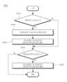
도 5는 일 실시예에 따른 물체감지방법의 흐름도를 도시한 도면이다.
도 6은 일 실시예에 따른 제어단계의 동작을 설명하기 위한 제1예를 도시한 도면이다.
도 7은 일 실시예에 따른 제어단계의 동작을 설명하기 위한 제2예를 도시한 도면이다.
도 8은 일 실시예에 따른 제어단계의 동작을 설명하기 위한 제3예를 도시한 도면이다.
도 9는 일 실시예에 따른 제어단계의 동작을 설명하기 위한 제4예를 도시한 도면이다.1 is a diagram showing an example for explaining problems occurring in a general object sensing device.
2 is a diagram showing the configuration of an object detection system according to an embodiment.
3 is a diagram illustrating an example for explaining an operation of an object detection system according to an exemplary embodiment.
4A and 4B are diagrams illustrating another example for explaining an operation of an object detection system according to an exemplary embodiment.
5 is a flowchart illustrating a method for detecting an object according to an exemplary embodiment.
6 is a diagram showing a first example for explaining the operation of a control step according to an embodiment.
7 is a diagram showing a second example for explaining the operation of a control step according to an embodiment.
8 is a diagram showing a third example for explaining the operation of a control step according to an embodiment.
9 is a diagram showing a fourth example for explaining the operation of a control step according to an embodiment.
이하, 일부 실시예들은 예시적인 도면을 참조하여 상세하게 설명한다. 각 도면의 구성요소들에 참조부호를 부가함에 있어서, 동일한 구성요소들에 대해서는 비록 다른 도면상에 표시되더라도 가능한 한 동일한 부호를 가질 수 있다. 또한, 본 실시예를 설명함에 있어, 관련된 공지 구성 또는 기능에 대한 구체적인 설명이 본 기술적 사상의 요지를 흐릴 수 있다고 판단되는 경우에는 그 상세한 설명은 생략할 수 있다.Hereinafter, some embodiments are described in detail with reference to exemplary drawings. In adding reference numerals to components of each drawing, the same components may have the same numerals as much as possible even if they are displayed on different drawings. In addition, in describing the present embodiment, if it is determined that a detailed description of a related known configuration or function may obscure the gist of the present technical idea, the detailed description may be omitted.
또한, 본 실시예의 구성 요소를 설명하는 데 있어서, 제 1, 제 2, A, B, (a), (b) 등의 용어를 사용할 수 있다. 이러한 용어는 그 구성 요소를 다른 구성 요소와 구별하기 위한 것일 뿐, 그 용어에 의해 해당 구성 요소의 본질, 차례, 순서 또는 개수 등이 한정되지 않는다. 어떤 구성 요소가 다른 구성요소에 "연결", "결합" 또는 "접속"된다고 기재된 경우, 그 구성 요소는 그 다른 구성요소에 직접적으로 연결되거나 또는 접속될 수 있지만, 각 구성 요소 사이에 다른 구성 요소가 "개재"되거나, 각 구성 요소가 다른 구성 요소를 통해 "연결", "결합" 또는 "접속"될 수도 있다고 이해되어야 할 것이다.Also, terms such as first, second, A, B, (a), and (b) may be used in describing the components of the present embodiment. These terms are only used to distinguish the component from other components, and the nature, sequence, order, or number of the corresponding component is not limited by the term. When an element is described as being “connected,” “coupled to,” or “connected” to another element, that element is or may be directly connected to that other element, but intervenes between each element. It will be understood that may be "interposed", or each component may be "connected", "coupled" or "connected" through other components.
차량에 있어서, 송신빔을 송신하고 수신되는 수신빔에 기초하여 물체를 감지하는 물체감지장치(일 예를 들어, 레이더센서)가 널리 사용되고 있다. 이러한 물체감지장치는 송신빔과, 상기 송신빔이 물체에 반사되어 수신되는 정상-수신빔간 정보에 기초하여 상기 물체를 감지한다.In vehicles, an object sensing device (for example, a radar sensor) that transmits a transmission beam and detects an object based on a received reception beam is widely used. Such an object detecting apparatus detects an object based on a transmission beam and information between a normal-received beam obtained by reflection of the transmission beam on an object.
하지만, 이러한 물체감지장치를 사용하다 보면 송신빔이 물체에 반사되어 수신되는 수신빔뿐 아니라 다른 원인에 의해 발생하는 에러-수신빔에 의해 물체를 오감지하는 문제점이 발생할 수 있다. 이에 대해 도 1을 이용하여 자세히 설명한다.However, when using such an object sensing device, a problem of erroneously detecting an object may occur due to an error-received beam caused by other causes as well as a reception beam received by reflection of a transmission beam on an object. This will be described in detail with reference to FIG. 1 .
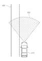
도 1은 일반적인 물체감지장치에서 발생하는 문제점을 설명하기 위한 일 예를 도시한 도면이다.1 is a diagram showing an example for explaining problems occurring in a general object sensing device.
도 1을 참조하면, 자차량(110)에 포함된 일반적인 물체감지장치는 정상-수신빔과 에러-수신빔을 수신할 수 있다. 상기 정상-수신빔은 자차량(110)에서 방사방향(120)을 향해 송신된 송신빔이 타차량(130)에 반사되어 수신되는 빔을 의미하며, 상기 에러-수신빔은 타차량(130)에서 방사방향(140)을 향해 송신된 송신빔이 직접 수신되는 빔을 의미할 수 있다.Referring to FIG. 1 , a general object detection device included in the
이러한 도 1과 같은 상황에서, 자차량(110)에 포함된 일반적인 물체감지장치는 에러-수신빔에 의해 자차량(110)과 타차량(130)사이에 물체가 존재하는 것으로 오감지하는 문제점이 발생할 수 있다.1, the general object detection device included in the
즉, 일반적인 물체감지 장치는 타차량 등 전방물체로부터 반사되어 수신되는 정상-수신빔을 이용하여 전방 물체를 감지하게 되는데, 전방 물체가 타차량인 경우 해당 타차량이 송신하는 송신빔에 의한 에러-수신빔이 더 수신되며, 이로 인하여 물체 감지의 정확도가 떨어질 수 있다는 것이다.That is, a general object detection device detects a forward object by using a normal reception beam reflected and received from a forward object such as another vehicle. More receive beams are received, and thus object detection accuracy may decrease.
특히, 전방 차량을 추종하는 적응 크루즈 컨트롤(Adaptive Cruise Control; ACC) 등에 사용되는 물체감지장치로서의 레이더 장치는 도 1과 같이 부채꼴 모양의 빔패턴(Beam Pattern)을 가지도록 송신빔을 방사한다. 하지만 이때 반대 차선에서 진행하는 타차량이 동일한 ACC를 사용하는 경우에는, 타차량의 레이더 장치에서도 같은 신호가 방사하게 되어 간섭(이는, 도 1에서 언급한 문제점에 포함됨)이 일어나게 된다.In particular, a radar device as an object detection device used in an adaptive cruise control (ACC) that follows a vehicle ahead emits a transmission beam to have a fan-shaped beam pattern as shown in FIG. 1 . However, at this time, when another vehicle traveling in the opposite lane uses the same ACC, the same signal is radiated from the radar device of the other vehicle, resulting in interference (which is included in the problem mentioned in FIG. 1).
이 때, 편파를 이용하여 크로스 편파(Cross Polarization)가 될 때에는 간섭을 일으키지 않지만 편파는 각 레이더 장치의 제조사마다 자유롭게 수직편파, 수평편파 또는 45도 편파를 선택적으로 사용할 수 있어, 경우에 따라서 동일한 편파방식을 사용하는 경우 간섭이 일어날 가능성이 크다.At this time, cross polarization using polarization does not cause interference, but each manufacturer of each radar device can freely selectively use vertical polarization, horizontal polarization, or 45 degree polarization, and in some cases the same polarization If the method is used, there is a high possibility that interference will occur.
이러한, 대항차량 등으로 인한 물체감지의 간섭 또는 장애를 막기 위해서 본 발명에서는 물체를 감지한 경우 송신빔이 감지된 물체쪽으로 향하지 않도록 송신빔의 방사방향을 조정하되, 주행 차로가 변경된 경우 방사방향을 초기방향으로 다시 복구하는 방안을 제안한다.In order to prevent object detection interference or obstacles caused by an opposing vehicle, in the present invention, when an object is detected, the radiation direction of the transmission beam is adjusted so that the transmission beam is not directed toward the detected object, but the radiation direction is changed when the driving lane is changed. We propose a way to recover back to the initial direction.
이하에서는, 전술한 문제점을 해결할 수 있는 물체감지시스템에 대해 자세히 설명한다.Hereinafter, an object detection system capable of solving the above problems will be described in detail.
도 2는 일 실시예에 따른 물체감지시스템의 구성을 도시한 도면이다.2 is a diagram showing the configuration of an object detection system according to an embodiment.
도 2를 참조하면, 일 실시예에 따른 물체감지시스템(200)은 제어신호에 따른 방사방향으로 송신빔을 송신하는 송신부(210)와 방사방향으로부터 수신빔을 수신하여 감지신호를 출력하는 수신부(220)와 감지신호를 분석하여 물체를 감지하는 물체 감지부(230)와 주행차로의 변경여부를 감지하는 차로변경 감지부(240) 및 감지신호의 분석에 기초하여 방사방향을 감지된 물체와 관련된 제1방향으로 변경하는 제어신호를 출력하고, 주행차로가 변경된 것으로 감지되면 방사방향이 미리 설정된 초기방향으로 변경하는 제어신호를 출력하는 제어부(250)를 포함할 수 있다.Referring to FIG. 2 , an
송신부(210)는 방사방향을 변화시킬 수 있는 어레이(Array)안테나를 이용하여 송신빔을 송신할 수 있다. 자세히 설명하면, 어레이안테나를 구성하는 단위 어레이안테나 각각에 동일한 위상을 가지는 제어신호를 입력하면 송신빔은 단위 어레이안테나들의 배치에 대한 수직인 방사방향으로 송신될 수 있다. 이와 달리, 단위 어레이안테나 각각에 다른 위상을 가지는 제어신호가 입력되면 송신빔은 단위 어레이안테나들의 배치에 대한 수직이 아닌 임의의 방사방향으로 송신될 수 있다. 상기 다른 위상을 가지는 제어신호는, RF칩을 이용한 디지털 빔 포밍(digital beam forming) 기술에 기초하여 생성될 수 있다.The
즉, 다수의 어레이안테나를 포함하는 안테나를 사용하되, 단위 어레이안테나별로 상이한 위상의 제어신호를 입력하면, 송신빔의 방사방향으로 임의로 조정할 수 있다.That is, if an antenna including a plurality of array antennas is used, but a control signal having a different phase is input for each unit array antenna, the radiation direction of the transmission beam can be arbitrarily adjusted.
수신부(220)는 복수로 배치된 수신안테나를 이용하여 수신빔을 수신하며 감지신호를 출력할 수 있다. 자세히 설명하면 수신안테나는 수신빔을 수신하여 아날로그신호를 생성하고, 상기 아날로그신호를 디지털신호로 변환하여 감지신호를 출력할 수 있다. 여기서, 수신부(220)는 송신빔이 송신되는 방향인 방사방향으로부터 수신빔이 수신되도록 설정될 수도 있다.The
물체 감지부(230)는 출력된 감지신호를 분석하여 물체를 감지할 수 있다. 일 예를 들어, 물체 감지부(230)는 송신부(210)에서 송신빔을 송신하여 수신빔을 수신하는데 소요되는 시간과 상기 송신빔의 성분을 이용하여 하나 이상의 물체위치점을 생성하고, 상기 하나 이상의 물체위치점을 이용하여 물체정보를 감지할 수 있다. 만약, 송신빔이 주파수가 변조되는 연속파(FMCW, Frequency Modulated Continuous Wave)이면 물체 감지부(230)는 도플러 효과(Doppler effect)에 기초하여 물체의 위치 또는 물체의 속도를 감지할 수도 있다. 이와 같은 방법을 이용함으로써, 물체 감지부(230)는 정지된 물체인지, 같은 방향으로 이동하는 물체인지 또는 대항하는 방향으로 이동하는 물체인지를 감지할 수 있다.The
차로변경 감지부(240)는 차량에 포함된 감지센서를 이용하여 주행차로의 변경여부를 감지할 수 있다. 상기 감지센서는 도로 위의 차선을 감지할 수 있는 영상감지센서 또는 도로 위의 시설물을 감지할 수 있는 외부감지센서 또는 차량의 횡방향 움직임을 감지할 수 있는 내부감지센서를 포함할 수 있다.The lane
영상감지센서를 이용하는 경우, 차로변경 감지부(240)는 감지된 차선 개수 또는 차선과의 거리의 변화에 기초하여 차량이 주행차로를 변경하는지를 판단할 수 있다.In the case of using an image sensor, the lane
외부감지센서를 이용하는 경우, 차로변경 감지부(240)는 감지된 시설물과의 거리 변화에 기초하여 차량이 주행차로를 변경하는지를 판단할 수 있다.In the case of using an external sensor, the lane
내부감지센서를 이용하는 경우, 차로변경 감지부(240)는 차량의 횡방향 움직임이 미리 설정된 임계움직임 이상이면 차량이 주행차로를 변경하는지를 판단할 수 있다. 상기 내부센서는 조향각, 요레이트, 횡가속도 등을 감지할 수 있는 센서일 수 있다.In the case of using the internal sensor, the lane
제어부(250)는 수신부(220)에서 출력된 감지신호의 분석에 기초하여 송신빔이 송신되는 방사방향을 감지된 물체와 관련된 제1방향으로 변경하는 제어신호를 출력할 수 있다. 또한, 제어부(250)는 차로변경 감지부(240)에서 주행차로가 변경된 것으로 감지되면 송신빔이 송신되는 방사방향을 미리 설정된 초기방향으로 변경하는 제어신호를 출력할 수 있다.The
한편, 본 발명에서 송신빔의 방사방향을 조정하는 경우는 아래의 제1예 내지 제5예와 같은 경우를 예시할 수 있으나, 그에 한정되는 것은 아니며, 전방 물체에 의한 간섭을 회피하기 위한 모든 경우를 포함할 수 있다.Meanwhile, in the present invention, the case of adjusting the radiation direction of the transmission beam may be exemplified in the case of the first to fifth examples below, but is not limited thereto, and in all cases to avoid interference by a forward object. can include
이하에서는 송신빔의 방향을 조정하는 5가지 경우를 예시로서 설명한다.Hereinafter, five cases of adjusting the direction of a transmission beam will be described as examples.
제1예에서, 제어부(250)는 주파수영역에서 넓게 분포되는 백색잡음이 존재하는 것으로 감지신호가 분석되면 송신빔의 방사방향이 제1방향으로 변경되도록 상기 제어신호를 출력할 수 있다. 상기 백색잡음은 주파수와 그 성분이 포함되는 비율의 관계가 정규분포에 따라 어떤 주파수 대역 내에서 모든 주파수의 출력이 포함되어 있는 잡음을 의미한다. 상기 주파수영역은 고속 푸리에 변환(Fast Fourier Transform, FFT)을 이용하여 변환할 수 있으며, 상기 제1방향은 미리 설정된 백색잡음과 관계된 정보에 따라 설정될 수도 있다. 예를 들어, 백색잡음이 존재하는 주파수영역의 분포범위가 클수록 제1방향은 초기방향과 큰 각도차이를 가지도록 설정될 수도 있다.In the first example, the
이러한 제1예에 의하면, 자차량의 주행차로와 무관하기 때문에 자차량의 주행차로를 감지하기 위한 센서가 추가적으로 필요하지 않는 효과가 있다.According to this first example, since it is irrelevant to the driving lane of the own vehicle, there is an effect in that a sensor for detecting the driving lane of the own vehicle is not additionally required.
제2예에서, 제어부(250)는 시간영역에서 임펄스(Impulse)신호가 존재하는 것으로 감지신호가 분석되면 송신빔의 방사방향이 제1방향으로 변경되도록 상기 제어신호를 출력할 수 있다. 상기 임펄스신호는 극히 짧은 시간에 큰 진폭을 내는 전압, 전류 또는 충격파인 펄스신호의 단일을 의미하는 것으로서, 상기 진폭의 크기는 감지된 값들 중 제일 작은 값을 기준으로 산출될 수 있다. 상기 제1방향은 미리 설정된 임펄스신호와의 관계에 따라 설정될 수도 있다. 예를 들어, 감지된 임펄스신호의 개수가 많거나, 또는 임펄스신호의 크기가 클수록 제1방향은 초기방향과 큰 각도차이를 가지도록 설정될 수도 있다.In the second example, the
이러한 제2예에 의하면, 자차량의 주행차로와 무관하기 때문에 자차량의 주행차로를 감지하기 위한 센서가 추가적으로 필요하지 않는 효과가 있다.According to this second example, since it is irrelevant to the driving lane of the own vehicle, there is an effect that an additional sensor for detecting the driving lane of the own vehicle is not required.
제3에서, 제어부(250)는 물체로서 대항차량이 감지되면 송신빔의 방사방향이 상기 대항차량이 존재하는 방향과 상이한 제1방향으로 변경되도록 상기 제어신호를 출력할 수 있다.Thirdly, when an oncoming vehicle as an object is detected, the
이에 대해, 도 3을 참조하여 설명한다.This will be described with reference to FIG. 3 .
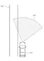
도 3은 일 실시예에 따른 물체감지시스템의 동작을 설명하기 위한 일 예를 도시한 도면이다.3 is a diagram illustrating an example for explaining an operation of an object detection system according to an exemplary embodiment.
도 3을 참조하면, 물체 감지부(230)는 물체(330)의 상대속도의 크기가 자차량(310)의 절대속도의 크기 또는 물체(330)의 절대속도의 크기보다 크면 물체(330)를 대항차량으로 감지할 수 있다. 이를 위해, 자차량(310)의 절대속도, 물체(330)의 절대속도 및 물체(330)의 상대속도를 감지하는 속도 감지부가 더 포함될 수 있다. 상기 속도 감지부는 차속센서 또는 휠속센서 등을 이용하여 자차량(310)의 절대속도를 감지할 수 있고, 물체(330)와 통신할 수 있는 장치를 이용하여 물체(330)의 절대속도를 감지할 수 있으며, 카메라센서 등을 이용하여 물체(330)의 상대속도를 감지할 수 있으나 이에 한정되는 것은 아니다.Referring to FIG. 3 , the
제3예에 의한 제어부(250)는 송신빔이 대항차량으로 감지된 물체(330)가 존재하는 방향(위치 및 각도를 포함할 수 있음)과 상이한 방향인 제1방향(320)으로 송신되도록 제어신호를 출력할 수 있다. 이와 같은 동작에 의해, 타차량(330)에서 송신되는 송신빔은 자차량(310)이 존재하는 방향과 상이한 방향(340)으로 송신될 수 있다. 이러한 제3예에 의하면, 자차량의 주행차로와 무관하기 때문에 자차량의 주행차로를 감지하기 위한 센서가 추가적으로 필요하지 않는 효과가 있다.The
제4예에서, 제어부(250)는 주행차로를 추정할 수 있는 물체가 감지되면 주행차로를 추정하고, 추정된 주행차로에 기초하여 상기 제1방향을 설정하며, 송신빔의 방사방향이 제1방향으로 변경되도록 상기 제어신호를 출력할 수 있다. 제 4예의 경우, 제어부(250)는 주행차로를 추정할 수 있는 물체를 감지하기 위해 미리 설정된 시간간격으로 송신빔의 방사방향이 초기방향으로 변경되도록 제어신호를 출력할 수 있다. 즉, 제4예에 따르면 일 실시예에 따른 물체감지시스템은 기본적인 센서(송신빔을 송신하여 수신빔을 수신하여 물체를 감지하는 센서로서, 레이더센서일 수 있음)만을 이용하여 동작할 수 있는 효과가 있다.In the fourth example, the
이에 대해 도 4a 및 도 4b를 참조한다.See FIGS. 4A and 4B for this.
도 4a 및 도 4b는 일 실시예에 따른 물체감지시스템의 동작을 설명하기 위한 다른 일 예를 도시한 도면이다.4A and 4B are diagrams illustrating another example for explaining an operation of an object detection system according to an exemplary embodiment.
도 4a를 참조하면, 물체 감지부(230)는 방사방향(420)에 의해 출력된 감지신호를 이용하여 주행차로를 추정할 수 있는 물체인 중앙분리대(430)를 감지할 수 있다. 자세히 설명하면, 제어부(250)는 중앙분리대(430)와의 거리와 미리 알고 있는 차로의 폭을 이용하여 자차량(410)의 주행차로를 제2차로로 추정할 수 있다.Referring to FIG. 4A , the
도 4b를 참조하면, 제어부(250)는 추정된 자차량(410)의 주행차로에 기초하여 송신빔이 중앙분리대(430)를 넘지 않도록 하는 제1방향(420')을 설정할 수 있다. 즉, 제어부(250)는 송신빔이 중앙분리대(430)를 넘지 않도록 하는 제1방향(420')으로 송신되도록 제어신호를 출력할 수 있다.Referring to FIG. 4B , the
한편, 제4예에 따른 제어부(250)는 중앙분리대를 포함하는 도로 시설물을 감지하기 위해 미리 설정된 시간간격으로 송신빔이 송신되는 방사방향이 초기방향으로 변경되도록 제어신호를 출력할 수도 있다. 이러한, 제4예에 의하면 기본적인 센서(송신빔을 송신하여 수신빔을 수신하여 물체를 감지하는 센서로서, 레이더센서일 수 있음)만을 이용하여 동작할 수 있는 효과가 있다.Meanwhile, the
제5예에서, 제어부(250)는 감지된 주행차로에 기초하여 송신빔이 반대차선을 넘지 않도록 하는 제1방향을 설정할 수 있다. 즉, 제어부(250)는 송신빔이 반대차선을 넘지 않도록 하는 제1방향으로 송신되도록 제어신호를 출력할 수 있다. 이를 위해, 카메라센서, 초음파센서 또는 통신장치 등의 추가장치가 출력한 정보에 기초하여 주행차로를 감지하는 주행차로 감지부가 더 포함될 수 있다.In the fifth example, the
카메라센서로부터 감지된 영상정보를 이용하는 경우, 주행차로 감지부는 미리 설정된 중앙차선의 색상(일반적으로 노랑색임)을 기준으로 자차량의 좌측(이는 우측통행인 교통체계에 따른 것으로서, 좌측통행인 교통체계에서는 자차량의 우측일 수 있음)에서 감지된 차선 개수에 기초하여 주행차로를 감지할 수 있다. 일 예를 들어, 자차량의 좌측에서 감지된 차선이 중앙차선의 색상을 기준으로 n(자연수)개의 흰색 차선이 감지되는 경우, 주행차로 감지부는 주행차로가 제(n+1)차로임을 감지할 수 있다.In the case of using the image information detected by the camera sensor, the driving lane detection unit is based on the color of the center lane (usually yellow) set in advance to the left side of the host vehicle (this is according to the right-hand traffic system, and in the left-hand traffic system The driving lane may be detected based on the number of lanes detected on the right side of the vehicle). For example, when n (natural number) white lanes are detected based on the color of the center lane in the lane detected from the left side of the own vehicle, the driving lane detector detects that the driving lane is the (n+1)th lane. can
초음파센서로부터 감지된 물체정보를 이용하는 경우, 주행차로 감지부는 미리 설정된 도로시설물(중앙분리대, 연석, 가드레일 등)과의 거리와 차로폭에 기초하여 주행차로를 감지할 수 있다.In the case of using the object information detected by the ultrasonic sensor, the driving lane detecting unit may detect the driving lane based on the distance to a preset road facility (median strip, curb, guardrail, etc.) and the lane width.
통신장치로부터 감지된 위치정보를 이용하는 경우, 주행차로 감지부는 위치정보와 상기 위치정보에 대응되는 차로정보에 기초하여 주행차로를 감지할 수 있다. 상기 차로정보는 통신장치로부터 감지되거나 또는 메모리에 미리 저장될 수 있다.이러한 제5예에 의하면 독립된 추가장치로부터 주행차로정보를 획득함에 따른 단순한 동작에 의해 동작오류가 감소될 수 있는 효과가 있다.In the case of using the location information sensed from the communication device, the driving lane detecting unit may detect the driving lane based on the location information and lane information corresponding to the location information. The lane information may be sensed from a communication device or stored in a memory in advance. According to the fifth example, an operation error can be reduced by a simple operation according to obtaining driving lane information from an independent additional device.
이상에서 설명한 바와 같이, 본 발명에서 제1예 내지 제5예 각각에 대한 경우를 적용하여 송신빔의 방사방향을 조정할 수 있으나, 송신빔의 방사방향을 보다 정밀하게 조정하기 위해 제1예 내지 제5예를 복합적으로 적용할 수도 있다.As described above, the radiation direction of the transmission beam can be adjusted by applying the cases for each of the first to fifth examples in the present invention, but in order to more precisely adjust the radiation direction of the transmission beam, the first to fifth examples The five examples may be applied in combination.
즉, 자차량의 주행차로가 1차로에 가까울수록 제어부(250)는 송신빔이 초기방향과 큰 각도차이를 가지는 제1방향으로 송신되도록 제어신호를 출력할 수 있다.That is, as the driving lane of the own vehicle is closer to the first lane, the
한편, 감지신호의 분석 변화량이 미비할 경우 제어부(250)는 상기 분석 변화량을 반영하지 못한 제어신호를 출력하는 한계가 발생할 수 있다. 이러한 한계는 외부요인(일 예를 들어, 감지 성능 저하 또는 데이터 처리 성능 저하 등)에 의해 발생될 수 있다. 또한, 방사방향이 제1방향으로 변경된 상태에서 자차량이 외곽측으로 주행차로를 변경하면 송신빔이 1차로측에 송신되지 않아 상기 1차로에 위치하는 물체를 감지하지 못하는 문제점이 발생할 수 있다.On the other hand, if the analysis change amount of the detection signal is insufficient, the
이러한 한계를 극복하고자, 제어부(250)는 주행차로가 변경된 것으로 감지되면 송신빔이 송신되는 방사방향을 초기방향으로 변경할 수 있다. 이로써, 분석 변화량이 증가됨으로써 제어부(250)는 보다 정확한 제어신호를 출력할 수 있는 효과가 발생할 수 있다. 또한, 자차량이 외곽측으로 주행차로를 변경하더라도 송신빔이 1차로측에 송신되어 상기 1차로에 위치하는 물체를 감지할 수 있는 효과가 발생할 수 있다.To overcome this limitation, the
도 2 내지 도 4b를 이용하여 설명한 일 실시예에 따른 물체감지시스템은 도 1에서 언급한 에러-수신빔(타차량에서 송신되는 송신빔이 직접 수신되는 빔을 의미함)을 차단할 수 있어 오감지되는 문제점이 해결될 수 있다.The object detection system according to the embodiment described with reference to FIGS. 2 to 4B can block the error-reception beam mentioned in FIG. 1 (meaning a beam in which a transmission beam transmitted from another vehicle is directly received), thereby detecting false positives. problem can be solved.
실제, 일 실시 예에 따른 물체감지시스템을 이용하여 3[dB]의 대역폭을 가지는 LRR-10을 포함하는 일반적인 레이더센서를 좌측 또는 우측으로 5도만큼 변화시킨다면 도 1에서 언급한 문제점을 해결할 수 있을 것으로 예상된다.In fact, if a general radar sensor including an LRR-10 having a bandwidth of 3 [dB] is changed by 5 degrees to the left or right using the object detection system according to an embodiment, the problem mentioned in FIG. 1 can be solved. It is expected.
이하에서는 도 2 내지 도 4b를 이용하여 설명한 물체감지시스템이 수행하는 동작인 물체감지방법에 대해서 간략하게 설명한다.Hereinafter, an object sensing method, which is an operation performed by the object sensing system described with reference to FIGS. 2 to 4B, will be briefly described.
도 5는 일 실시예에 따른 물체감지방법의 흐름도를 도시한 도면이다.5 is a flowchart illustrating a method for detecting an object according to an exemplary embodiment.
도 5를 참조하면, 일 실시예에 따른 물체감지방법은 제어신호에 따른 방사방향으로 송신빔을 송신하는 송신단계(S500)와 방사방향으로부터 수신빔을 수신하여 감지신호를 출력하는 수신단계(S510)와 감지신호를 분석하여 물체를 감지하는 물체 감지단계(S520)와 주행차로의 변경여부를 감지하는 차로변경 감지단계(S530) 및 감지신호의 분석에 기초하여 방사방향을 감지된 물체와 관련된 제1방향으로 변경하는 제어신호를 출력하고, 주행차로가 변경된 것으로 감지되면 방사방향이 미리 설정된 초기방향으로 변경하는 제어신호를 출력하는 제어단계(S540)를 포함할 수 있다.Referring to FIG. 5 , the object sensing method according to an embodiment includes a transmission step of transmitting a transmission beam in a radial direction according to a control signal (S500) and a receiving step of outputting a detection signal by receiving a reception beam from the radial direction (S510). ) and an object detection step (S520) of detecting an object by analyzing the detection signal, a lane change detection step (S530) of detecting whether or not the driving lane has changed, and a control system related to the detected object based on the analysis of the detection signal A control step (S540) of outputting a control signal for changing in one direction and outputting a control signal for changing the radial direction to a preset initial direction when it is detected that the driving lane has changed may be included.
송신단계(S500)는 방사방향을 변화시킬 수 있는 어레이(Array)안테나를 이용하여 송신빔을 송신할 수 있다. 자세히 설명하면, 어레이안테나를 구성하는 단위 어레이안테나 각각에 동일한 위상을 가지는 제어신호를 입력하면 송신빔은 단위 어레이안테나들의 배치에 대한 수직인 방사방향으로 송신될 수 있다. 이와 달리, 단위 어레이안테나 각각에 다른 위상을 가지는 제어신호가 입력되면 송신빔은 단위 어레이안테나들의 배치에 대한 수직이 아닌 임의의 방사방향으로 송신될 수 있다. 상기 다른 위상을 가지는 제어신호는, RF칩을 이용한 디지털 빔 포밍(digital beam forming) 기술에 기초하여 생성될 수 있다.In the transmission step (S500), a transmission beam may be transmitted using an array antenna capable of changing a radiation direction. In detail, when a control signal having the same phase is input to each of the unit array antennas constituting the array antenna, the transmission beam can be transmitted in a radial direction perpendicular to the arrangement of the unit array antennas. Alternatively, if a control signal having a different phase is input to each of the unit array antennas, the transmission beam may be transmitted in an arbitrary radial direction other than perpendicular to the arrangement of the unit array antennas. The control signals having different phases may be generated based on digital beam forming technology using an RF chip.
즉, 다수의 어레이안테나를 포함하는 안테나를 사용하되, 단위 어레이안테나별로 상이한 위상의 제어신호를 입력하면, 송신빔의 방사방향으로 임의로 조정할 수 있다.That is, if an antenna including a plurality of array antennas is used, but a control signal having a different phase is input for each unit array antenna, the radiation direction of the transmission beam can be arbitrarily adjusted.
수신단계(S510)는 복수로 배치된 수신안테나를 이용하여 수신빔을 수신하며 감지신호를 출력할 수 있다. 자세히 설명하면 수신안테나는 수신빔을 수신하여 아날로그신호를 생성하고, 상기 아날로그신호를 디지털신호로 변환하여 감지신호를 출력할 수 있다. 여기서, 수신단계(S510)는 송신빔이 송신되는 방향인 방사방향으로부터 수신빔이 수신되도록 설정할 수도 있다.In the receiving step (S510), a reception beam may be received using a plurality of arranged reception antennas and a detection signal may be output. In detail, the reception antenna may generate an analog signal by receiving a reception beam, convert the analog signal into a digital signal, and output a detection signal. Here, in the receiving step (S510), the reception beam may be set to be received from the radiation direction, which is the direction in which the transmission beam is transmitted.
물체 감지단계(S520)는 출력된 감지신호를 분석하여 물체를 감지할 수 있다. 자세히 설명하면, 물체 감지단계(S520)는 송신단계(S500)에서 송신빔을 송신하여 수신빔을 수신하는데 소요되는 시간과 상기 송신빔의 성분을 이용하여 하나 이상의 물체위치점을 생성하고, 상기 하나 이상의 물체위치점을 이용하여 물체를 감지할 수 있다. 이와 같은 방법을 이용함으로써, 물체 감지부(230)는 정지된 물체인지, 같은 방향으로 이동하는 물체인지 또는 대항하는 방향으로 이동하는 물체인지를 감지할 수 있다.In the object detection step (S520), an object may be detected by analyzing the output detection signal. In detail, the object detection step (S520) generates one or more object location points using the time required to transmit the transmission beam and receive the reception beam in the transmission step (S500) and the components of the transmission beam, An object can be detected using the above object location points. By using this method, the
차로변경 감지단계(S530)는 차량에 포함된 감지센서를 이용하여 주행차로의 변경여부를 감지할 수 있다. 상기 감지센서는 도로 위의 차선을 감지할 수 있는 영상감지센서 또는 도로 위의 시설물을 감지할 수 있는 외부감지센서 또는 차량의 횡방향 움직임을 감지할 수 있는 내부감지센서를 포함할 수 있다.In the lane change detection step (S530), whether or not the driving lane is changed may be detected using a sensor included in the vehicle. The detection sensor may include an image detection sensor capable of detecting lanes on the road, an external detection sensor capable of detecting facilities on the road, or an internal detection sensor capable of detecting lateral movement of the vehicle.
영상감지센서를 이용하는 경우, 차로변경 감지단계(S530)는 감지된 차선 개수 또는 차선과의 거리의 변화에 기초하여 차량이 주행차로를 변경하는지를 판단할 수 있다.In the case of using an image detection sensor, in the lane change detection step (S530), it may be determined whether the vehicle changes the driving lane based on the detected change in the number of lanes or the distance from the lane.
외부감지센서를 이용하는 경우, 차로변경 감지단계(S530)는 감지된 시설물과의 거리 변화에 기초하여 차량이 주행차로를 변경하는지를 판단할 수 있다.In the case of using an external sensor, the lane change detection step (S530) may determine whether the vehicle changes the driving lane based on the detected distance change from the facility.
내부감지센서를 이용하는 경우, 차로변경 감지단계(S530)는 차량의 횡방향 움직임이 미리 설정된 임계움직임 이상이면 차량이 주행차로를 변경하는지를 판단할 수 있다. 상기 내부센서는 요레이트, 횡가속도 등을 감지할 수 있는 센서일 수 있다.In the case of using the internal sensor, in the lane change detection step (S530), if the lateral movement of the vehicle is equal to or greater than a preset threshold movement, it may be determined whether the vehicle changes the driving lane. The internal sensor may be a sensor capable of detecting a yaw rate, a lateral acceleration, and the like.
제어단계(S540)는 수신단계(S510)에서 출력된 감지신호의 분석에 기초하여 송신빔이 송신되는 방사방향을 감지된 물체와 관련된 제1방향으로 변경하는 제어신호를 출력할 수 있다. 또한, 제어단계(S540)는 차로변경 감지단계(S530)에서 주행차로가 변경된 것으로 감지되면 송신빔이 송신되는 방사방향을 미리 설정된 초기방향으로 변경하는 제어신호를 출력할 수 있다.In the control step (S540), based on the analysis of the detection signal output in the receiving step (S510), a control signal for changing a radiation direction in which the transmission beam is transmitted to a first direction related to the sensed object may be output. In addition, in the control step (S540), when it is detected that the driving lane is changed in the lane change detection step (S530), a control signal for changing the radiation direction in which the transmission beam is transmitted to a preset initial direction may be output.
한편, 감지신호의 분석 변화량이 미비할 경우 제어단계(S540)는 상기 분석 변화량을 반영하지 못한 제어신호를 출력하는 한계가 발생할 수 있다. 이러한 한계는 외부요인(일 예를 들어, 감지 성능 저하 또는 데이터 처리 성능 저하 등)에 의해 발생될 수 있다. 또한, 방사방향이 제1방향으로 변경된 상태에서 자차량이 외곽측으로 주행차로를 변경하면 송신빔이 1차로측에 송신되지 않아 상기 1차로에 위치하는 물체를 감지하지 못하는 문제점이 발생할 수 있다.On the other hand, if the analysis change amount of the detection signal is insufficient, the control step (S540) may cause a limitation of outputting a control signal that does not reflect the analysis change amount. These limitations may be caused by external factors (eg, degradation of sensing performance or degradation of data processing performance). In addition, if the own vehicle changes the driving lane to the outer side in a state where the radial direction is changed to the first direction, a transmission beam is not transmitted to the first lane, and thus an object located on the first lane cannot be detected.
이러한 한계를 극복하고자, 제어단계(S540)는 주행차로가 변경된 것으로 감지되면 송신빔이 송신되는 방사방향을 초기방향으로 변경할 수 있다.To overcome this limitation, in the control step (S540), when it is detected that the driving lane is changed, the radiation direction in which the transmission beam is transmitted may be changed to the initial direction.
상기 제어단계(S540)는 아래의 도 6 내지 도 9과 같이 동작할 수 있으나, 그에 한정되는 것은 아니며, 전방 물체에 의한 간섭을 회피하기 위해 방사방향을 변경할 수 있는 모든 경우를 포함할 수 있다.The control step (S540) may operate as shown in FIGS. 6 to 9 below, but is not limited thereto, and may include all cases in which the radial direction can be changed to avoid interference by a forward object.
제어단계(S540)는 도 6와 같이 동작할 수 있다.The control step (S540) may operate as shown in FIG.
도 6은 일 실시예에 따른 제어단계의 동작을 설명하기 위한 제1예를 도시한 도면이다.6 is a diagram showing a first example for explaining the operation of a control step according to an embodiment.
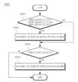
도 6을 참조하면, 제어단계는 주파수영역에서 넓게 분포되는 백색잡음 또는 시간영역에서 임펄스(Impulse)신호가 존재하는 것으로 분석되었지 판단할 수 있다(S541a). 상기 백색잡음은 주파수와 그 성분이 포함되는 비율의 관계가 정규분포에 따라 어떤 주파수 대역 내에서 모든 주파수의 출력이 포함되어 있는 잡음을 의미하며, 상기 임펄스신호는 극히 짧은 시간에 큰 진폭을 내는 전압, 전류 또는 충격파인 펄스신호의 단일을 의미하는 것으로서, 상기 진폭의 크기는 감지된 값들 중 제일 작은 값을 기준으로 산출될 수 있다. 또한, 상기 주파수영역은 고속푸리에변환(Fast Fourier Transform, FFT)을 이용하여 변환할 수 있다.Referring to FIG. 6, in the control step, it may be determined whether white noise widely distributed in the frequency domain or an impulse signal in the time domain has been analyzed (S541a). The white noise refers to noise in which the output of all frequencies is included in a certain frequency band according to a normal distribution in which the relationship between frequency and the ratio of the components thereof is normally distributed, and the impulse signal is a voltage generating a large amplitude in an extremely short time , which means a single pulse signal that is a current or shock wave, and the size of the amplitude can be calculated based on the smallest value among detected values. In addition, the frequency domain can be transformed using Fast Fourier Transform (FFT).
S541 단계에서, 백색잡음 또는 임펄스신호가 존재하는 것으로 분석되면(YES), 제어단계는 송신빔의 방사방향이 제1방향으로 변경되도록 제어신호를 출력할 수 있다(S543a). 상기 제1방향은 미리 설정된 백색잡음과 관계된 정보에 따라 설정될 수도 있다. 예를 들어, 백색잡음이 존재하는 주파수영역의 분포범위가 클수록 초기방향과 큰 각도차이를 가지는 제1방향이 설정될 수도 있다.In step S541, if it is analyzed that the white noise or impulse signal exists (YES), the control step may output a control signal to change the radiation direction of the transmission beam to the first direction (S543a). The first direction may be set according to previously set information related to white noise. For example, as the distribution range of the frequency domain in which white noise is present increases, a first direction having a greater angular difference from the initial direction may be set.
S543a 단계가 수행되거나 또는 S541a 단계에서 NO로 판단되면, 제어단계는 주행차로 변경이 감지되는지 판단할 수 있다(S545a).If step S543a is performed or it is determined as NO in step S541a, the control step may determine whether a driving lane change is detected (S545a).
S545a 단계에서, 주행차로 변경이 감지된 것으로 판단되면(YES), 제어단계는 송신빔의 방사방향이 초기방향으로 변경되도록 제어신호를 출력할 수 있다(S547a).In step S545a, if it is determined that the driving lane change is detected (YES), the control step may output a control signal to change the radiation direction of the transmission beam to the initial direction (S547a).
도 6과 같은 제어단계(S540)에 의하면, 자차량의 주행차로와 무관하기 때문에 자차량의 주행차로를 감지하기 위한 센서가 추가적으로 필요하지 않는 효과가 있다.According to the control step (S540) as shown in FIG. 6, since it is irrelevant to the driving lane of the host vehicle, there is an effect in that a sensor for detecting the driving lane of the host vehicle is not additionally required.
또는, 제어단계(S540)는 도 7과 같이 동작할 수도 있다.Alternatively, the control step (S540) may operate as shown in FIG.
도 7은 일 실시예에 따른 제어단계의 동작을 설명하기 위한 제2예를 도시한 도면이다.7 is a diagram showing a second example for explaining the operation of a control step according to an embodiment.
도 7을 참조하면, 제어단계는 물체의 상대속도의 크기가 상기 자차량의 절대속도의 크기 또는 상기 물체의 절대속도의 크기보다 큰지를 판단할 수 있다(S541b). 이를 위해, 자차량의 절대속도, 상기 물체의 절대속도 및 상기 물체의 상대속도를 감지하는 속도 감지단계가 미리 수행될 수 있다. 상기 속도 감지단계는 차속센서 또는 휠속센서 등을 이용하여 자차량의 절대속도를 감지할 수 있고, 물체와 통신할 수 있는 장치를 이용하여 물체의 절대속도를 감지할 수 있으며, 카메라센서 등을 이용하여 물체의 상대속도를 감지할 수 있으나 이에 한정되는 것은 아니다.Referring to FIG. 7 , the control step may determine whether the relative speed of the object is greater than the absolute speed of the host vehicle or the absolute speed of the object (S541b). To this end, a speed sensing step of detecting the absolute speed of the vehicle, the absolute speed of the object, and the relative speed of the object may be performed in advance. In the speed detection step, the absolute speed of the own vehicle can be detected using a vehicle speed sensor or a wheel speed sensor, the absolute speed of the object can be detected using a device capable of communicating with the object, and the absolute speed of the object can be detected using a camera sensor or the like. Thus, the relative speed of the object can be sensed, but is not limited thereto.
S541b 단계에서 물체의 상대속도의 크기가 상기 자차량의 절대속도의 크기 또는 상기 물체의 절대속도의 크기보다 큰 것으로 판단되면(YES), 제어단계는 송신빔의 방사방향이 제1방향으로 변경되도록 제어신호를 출력할 수 있다(S543b).In step S541b, if it is determined that the relative speed of the object is greater than the absolute speed of the own vehicle or the absolute speed of the object (YES), the control step changes the radiation direction of the transmission beam to the first direction. A control signal can be output (S543b).
S543b 단계가 수행되거나 또는 S541b 단계에서 NO로 판단되면, 제어단계는 주행차로 변경이 감지되는지 판단할 수 있다(S545b).If step S543b is performed or it is determined as NO in step S541b, the control step may determine whether a driving lane change is detected (S545b).
S545b 단계에서, 주행차로 변경이 감지된 것으로 판단되면(YES), 제어단계는 송신빔의 방사방향이 초기방향으로 변경되도록 제어신호를 출력할 수 있다(S547b).In step S545b, if it is determined that the driving lane change is detected (YES), the control step may output a control signal to change the radiation direction of the transmission beam to the initial direction (S547b).
도 7과 같은 제어단계(S540)에 의하면, 자차량의 주행차로와 무관하기 때문에 자차량의 주행차로를 감지하기 위한 센서가 추가적으로 필요하지 않는 효과가 있다.According to the control step (S540) as shown in FIG. 7, since it is irrelevant to the driving lane of the host vehicle, there is an effect in that a sensor for detecting the driving lane of the host vehicle is not additionally required.
또는, 제어단계(S540)는 도 8과 같이 동작할 수도 있다.Alternatively, the control step (S540) may operate as shown in FIG.
도 8은 일 실시예에 따른 제어단계의 동작을 설명하기 위한 제3예를 도시한 도면이다.8 is a diagram showing a third example for explaining the operation of a control step according to an embodiment.
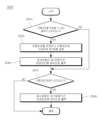
도 8을 참조하면, 제어단계는 주행차로를 추정할 수 있는 물체가 감지되는지 판단할 수 있다(S541c). 상기 주행차로를 추정할 수 있는 물체는 중앙분리대를 포함하는 도로 시설물일 수 있다.Referring to FIG. 8 , the control step may determine whether an object capable of estimating a driving lane is detected (S541c). An object capable of estimating the driving lane may be a road facility including a median strip.
S541c 단계에서 주행차로를 추정할 수 있는 물체가 감지된 것으로 판단되면(YES), 제어단계는 주행차로를 추정하고 주행차로에 기초하여 제1방향을 설정할 수 있다(S543c). 일 예를 들어, S543c 단계는 주행차로를 추정할 수 있는 물체와의 거리와 미리 알고 있는 차로폭을 이용하여 주행차로가 1차로인지, 2차로인지 또는 그 외 차로인지를 추정할 수 있다. 이에, S543c 단계는 추정된 주행차로에 기초하여 송신빔이 반대차로에 송신되지 않도록 하는 제1방향을 설정할 수 있다.If it is determined in step S541c that an object capable of estimating the driving lane is detected (YES), the control step may estimate the driving lane and set the first direction based on the driving lane (S543c). For example, in step S543c, whether the driving lane is a first lane, a second lane, or other lanes may be estimated using a distance to an object capable of estimating the driving lane and a previously known lane width. Therefore, in step S543c, a first direction for preventing transmission beams from being transmitted to the opposite lane may be set based on the estimated driving lane.
S543c 단계가 수행되면, 제어단계는 송신빔이 송신되는 방사방향이 제1방향으로 변경되도록 제어신호를 출력할 수 있다(S545c).When step S543c is performed, the control step may output a control signal so that the radiation direction in which the transmission beam is transmitted is changed to the first direction (S545c).
S545c 단계가 수행되거나 또는 S541c 단계에서 NO로 판단되면, 제어단계는 주행차로 변경이 감지되는지 판단할 수 있다(S547c).If step S545c is performed or step S541c determines NO, the control step may determine whether a driving lane change is detected (S547c).
S547c 단계에서, 주행차로 변경이 감지된 것으로 판단되면(YES), 제어단계는 송신빔의 방사방향이 초기방향으로 변경되도록 제어신호를 출력할 수 있다(S549c).In step S547c, if it is determined that the driving lane change is detected (YES), the control step may output a control signal to change the radiation direction of the transmission beam to the initial direction (S549c).
한편, 도 8에서 제어단계는 중앙분리대를 포함하는 도로 시설물을 감지하기 위해 미리 설정된 시간간격으로 송신빔이 송신되는 방사방향이 초기방향으로 변경되도록 제어신호를 출력할 수도 있다. 즉, 도 8에 의하면 일 실시예에 따른 물체감지방법은 기본적인 센서(송신빔을 송신하여 수신빔을 수신하여 물체를 감지하는 센서로서, 레이더센서일 수 있음)만을 이용하여 동작할 수 있다.Meanwhile, in the control step of FIG. 8 , a control signal may be output such that a radial direction in which a transmission beam is transmitted is changed to an initial direction at preset time intervals in order to detect a road facility including a median strip. That is, according to FIG. 8 , the object sensing method according to an embodiment can operate using only a basic sensor (a sensor that detects an object by transmitting a transmission beam and receiving a reception beam, which may be a radar sensor).
또는, 제어단계(S540)는 도 9와 같이 동작할 수도 있다.Alternatively, the control step (S540) may operate as shown in FIG.
도 9는 일 실시예에 따른 제어단계의 동작을 설명하기 위한 제4예를 도시한 도면이다.9 is a diagram showing a fourth example for explaining the operation of a control step according to an embodiment.
도 9를 참조하면, 제어단계는 주행차로가 감지되는지 판단할 수 있다(S541d). 이를 위해, 영상정보에 기초하여 주행차로를 감지하는 주행차로 감지단계가 미리 수행될 수 있다. 여기서, 상기 주행차로 감지단계는 영상정보가 아닌 다른 정보에 기초하여 주행차로를 감지할 수도 있다.Referring to FIG. 9 , the control step may determine whether a driving lane is detected (S541d). To this end, a driving lane detection step of detecting the driving lane based on the image information may be performed in advance. Here, the driving lane sensing step may detect the driving lane based on information other than image information.
S541d 단계에서 주행차로가 감지된 것으로 판단되면(YES), 제어단계는 주행차로에 기초하여 제1방향을 설정할 수 있다(S543d). 일 예를 들어, S543d 단계는 추정된 주행차로에 기초하여 송신빔이 반대차로에 송신되지 않도록 하는 제1방향을 설정할 수 있다.If it is determined in step S541d that the driving lane is detected (YES), the control step may set the first direction based on the driving lane (S543d). For example, in step S543d, a first direction for not transmitting a transmission beam to an opposite lane may be set based on the estimated driving lane.
S543d 단계가 수행되면, 제어단계는 송신빔이 송신되는 방사방향이 제1방향으로 변경되도록 제어신호를 출력할 수 있다(S545d).When step S543d is performed, the control step may output a control signal so that the radiation direction in which the transmission beam is transmitted is changed to the first direction (S545d).
S545d 단계가 수행되거나 또는 S541d 단계에서 NO로 판단되면, 제어단계는 주행차로 변경이 감지되는지 판단할 수 있다(S547d).If step S545d is performed or step S541d determines NO, the control step may determine whether a driving lane change is detected (S547d).
S547d 단계에서, 주행차로 변경이 감지된 것으로 판단되면(YES), 제어단계는 송신빔의 방사방향이 초기방향으로 변경되도록 제어신호를 출력할 수 있다(S549d).In step S547d, if it is determined that the driving lane change is detected (YES), the control step may output a control signal so that the radiation direction of the transmission beam is changed to the initial direction (S549d).
도 9와 같이 동작하는 제어단계(S540)에 의하면, 기본적인 센서(송신빔을 송신하여 수신빔을 수신하여 물체를 감지하는 센서로서, 레이더센서일 수 있음)만을 이용하여 동작할 수 있는 효과가 있다.According to the control step (S540) operating as shown in FIG. 9, there is an effect of being able to operate using only a basic sensor (a sensor that detects an object by transmitting a transmission beam and receiving a reception beam, which may be a radar sensor). .
이 외에도 물체감지방법은 도 2 내지 도 4b에 기초하여 설명한 물체감지시스템이 수행하는 각 동작을 모두 수행할 수 있다.In addition to this, the object sensing method may perform all of the operations performed by the object sensing system described with reference to FIGS. 2 to 4B.
이상에서의 설명 및 첨부된 도면은 본 실시예의 기술 사상을 예시적으로 나타낸 것에 불과한 것으로서, 본 발명이 속하는 기술 분야에서 통상의 지식을 가진 자라면 본 발명의 본질적인 특성에서 벗어나지 않는 범위에서 구성의 결합, 분리, 치환 및 변경 등의 다양한 수정 및 변형이 가능할 것이다. 따라서, 개시된 실시예들은 기술적 사상을 한정하기 위한 것이 아니라 설명하기 위한 것이고, 이러한 실시예에 의하여 기술적 사상의 범위가 한정되는 것은 아니다. 본 실시예들의 보호 범위는 아래의 청구범위에 의하여 해석되어야 하며, 그와 동등한 범위 내에 있는 모든 기술 사상은 본 발명의 권리범위에 포함되는 것으로 해석되어야 할 것이다.The above description and accompanying drawings are merely illustrative of the technical idea of the present embodiment, and those skilled in the art can combine the configuration within the scope not departing from the essential characteristics of the present invention. , various modifications and variations such as separation, substitution and alteration will be possible. Therefore, the disclosed embodiments are intended to explain rather than limit the technical idea, and the scope of the technical idea is not limited by these embodiments. The scope of protection of the present embodiments should be construed according to the claims below, and all technical ideas within the equivalent range should be construed as being included in the scope of the present invention.
Claims (13)
Translated fromKorean상기 방사방향으로부터 수신빔을 수신하여 감지신호를 출력하는 수신부;
상기 감지신호를 분석하여 물체를 감지하는 물체 감지부;
주행차로의 변경여부를 감지하는 차로변경 감지부; 및
상기 감지신호의 분석결과에 기초하여 상기 방사방향을 변경하는 상기 제어신호를 출력하고, 상기 주행차로가 변경된 것으로 감지되면 상기 방사방향이 미리 설정된 초기방향으로 변경하는 상기 제어신호를 출력하는 제어부;
를 포함하되,
상기 감지신호는 백색잡음, 임펄스, 대항차량 존재여부, 주행차로 중 적어도 하나와 관련된 신호인 것을 특징으로 하는 차량용 물체감지시스템.a transmitter for transmitting a transmission beam in a radial direction according to a control signal;
a receiver configured to receive a reception beam from the radial direction and output a detection signal;
an object detector configured to detect an object by analyzing the detection signal;
a lane change detection unit that detects whether a driving lane has changed; and
a control unit outputting the control signal for changing the radial direction based on an analysis result of the detection signal, and outputting the control signal for changing the radial direction to a preset initial direction when it is detected that the driving lane is changed;
Including,
The object detection system for a vehicle, characterized in that the detection signal is a signal related to at least one of white noise, impulse, presence of an oncoming vehicle, and driving lane.
상기 제어부는,
주파수영역에서 넓게 분포되는 백색잡음(White noise)이 존재하는 것으로 상기 감지신호가 분석되면 상기 방사방향이 상기 백색잡음에 따라 다른 각도차이를 가지는 방향으로 변경되도록 상기 제어신호를 출력하는 것을 특징으로 하는 차량용 물체감지시스템.According to claim 1,
The control unit,
When the detection signal is analyzed as having white noise widely distributed in the frequency domain, the control signal is output so that the radiation direction is changed to a direction having a different angle difference according to the white noise. Vehicle object detection system.
상기 제어부는,
시간영역에서 임펄스(Impulse)신호가 존재하는 것으로 상기 감지신호가 분석되면 상기 방사방향이 임펄스 신호의 개수 또는 임펄스 신호의 크기에 따라 다른 각도차이를 가지는 방향으로 변경되도록 상기 제어신호를 출력하는 것을 특징으로 하는 차량용 물체감지시스템.According to claim 1,
The control unit,
When the detection signal is analyzed that an impulse signal exists in the time domain, the control signal is output so that the radiation direction is changed to a direction having a different angle difference according to the number of impulse signals or the magnitude of the impulse signal. Object detection system for vehicles.
상기 제어부는,
상기 물체로서 대항차량이 감지되면 상기 방사방향이 상기 대항차량이 존재하는 방향과 상이한 방향으로 변경되도록 상기 제어신호를 출력하는 것을 특징으로 하는 차량용 물체감지시스템.According to claim 1,
The control unit,
and when an oncoming vehicle is detected as the object, the control signal is output such that the radial direction is changed to a direction different from a direction in which the oncoming vehicle exists.
자차량의 절대속도, 상기 물체의 절대속도 및 상기 물체의 상대속도를 감지하는 속도 감지부를 더 포함하고,
상기 물체 감지부는,
상기 물체의 상대속도의 크기가 상기 자차량의 절대속도의 크기 또는 상기 물체의 절대속도의 크기보다 크면 상기 물체를 상기 대항차량으로 감지하는 것을 특징으로 하는 차량용 물체감지시스템.According to claim 4,
Further comprising a speed sensor for detecting the absolute speed of the vehicle, the absolute speed of the object, and the relative speed of the object;
The object detection unit,
and detecting the object as the opposing vehicle when the magnitude of the relative speed of the object is greater than the magnitude of the magnitude of the absolute velocity of the own vehicle or the magnitude of the absolute velocity of the object.
상기 제어부는,
주행차로를 추정할 수 있는 물체가 감지되면 상기 주행차로를 추정하고, 상기 주행차로에 기초하여 상기 방사방향이 변경되도록 상기 제어신호를 출력하는 것을 특징으로 하는 차량용 물체감지시스템.According to claim 1,
The control unit,
An object detection system for a vehicle, characterized in that, when an object capable of estimating a driving lane is detected, the driving lane is estimated, and the control signal is output so that the radial direction is changed based on the driving lane.
상기 제어부는,
상기 주행차로를 추정할 수 있는 물체를 감지하기 위해 미리 설정된 시간간격으로 상기 방사방향이 상기 초기방향으로 변경되도록 상기 제어신호를 출력하는 것을 특징으로 하는 차량용 물체감지시스템.According to claim 6,
The control unit,
An object detection system for a vehicle, characterized in that outputting the control signal so that the radial direction is changed to the initial direction at a preset time interval in order to detect an object from which the driving lane can be estimated.
상기 주행차로를 감지하는 주행차로 감지부를 더 포함하고,
상기 제어부는,
상기 주행차로에 기초하여 송신빔이 반대차선을 넘지 않도록 방사방향을 설정하며, 상기 방사방향이 변경되도록 상기 제어신호를 출력하는 것을 특징으로 하는 차량용 물체감지시스템.According to claim 1,
Further comprising a driving lane detection unit for detecting the driving lane,
The control unit,
An object detection system for a vehicle, characterized in that a radiation direction is set so that the transmission beam does not cross an opposite lane based on the driving lane, and the control signal is output so that the radiation direction is changed.
상기 방사방향으로부터 수신빔을 수신하여 감지신호를 출력하는 수신단계;
상기 감지신호를 분석하여 물체를 감지하는 물체 감지단계;
주행차로의 변경여부를 감지하는 차로변경 감지단계; 및
상기 감지신호의 분석결과에 기초하여 상기 방사방향을 변경하는 상기 제어신호를 출력하고, 상기 주행차로가 변경된 것으로 감지되면 상기 방사방향이 미리 설정된 초기방향으로 변경되도록 상기 제어신호를 출력하는 제어단계;
를 포함하되,
상기 감지신호는 백색잡음, 임펄스, 대항차량 존재여부, 주행차로 중 적어도 하나와 관련된 신호인 것을 특징으로 하는 차량용 물체감지방법.a transmission step of transmitting a transmission beam in a radial direction according to a control signal;
a reception step of receiving a reception beam from the radial direction and outputting a detection signal;
an object detection step of detecting an object by analyzing the detection signal;
Lane change detection step of detecting whether the driving lane is changed; and
a control step of outputting the control signal for changing the radial direction based on an analysis result of the detection signal, and outputting the control signal to change the radial direction to a preset initial direction when it is detected that the driving lane is changed;
Including,
The object detection method for a vehicle, characterized in that the detection signal is a signal related to at least one of white noise, impulse, presence of an oncoming vehicle, and driving lane.
상기 제어단계는,
주파수영역에서 넓게 분포되는 백색잡음(White noise)이 존재하는 것으로 상기 감지신호가 분석되면 상기 방사방향이 백색잡음에 따라 다른 각도차이를 가지는 방향으로 변경되도록 상기 제어신호를 출력하는 것을 특징으로 하는 차량용 물체감지방법.According to claim 9,
The control step is
When the detection signal is analyzed as the presence of white noise widely distributed in the frequency domain, the control signal is output so that the radiation direction is changed to a direction having a different angular difference according to the white noise. object detection method.
상기 제어단계는,
시간영역에서 임펄스(Impulse)신호가 존재하는 것으로 상기 감지신호가 분석되면 상기 방사방향이 임펄스 신호의 개수 또는 임펄스 신호의 크기에 따라 다른 각도차이를 가지는 방향으로 변경되도록 상기 제어신호를 출력하는 것을 특징으로 하는 차량용 물체감지방법.According to claim 9,
The control step is
When the detection signal is analyzed that an impulse signal exists in the time domain, the control signal is output so that the radiation direction is changed to a direction having a different angle difference according to the number of impulse signals or the magnitude of the impulse signal. A vehicle object detection method.
상기 제어단계는,
상기 물체로서 대항차량이 감지되면 상기 방사방향이 상기 대항차량이 존재하는 방향과 상이한 방향으로 변경되도록 상기 제어신호를 출력하는 것을 특징으로 하는 차량용 물체감지방법.
According to claim 9,
The control step is
When an oncoming vehicle is detected as the object, the control signal is output such that the radial direction is changed to a direction different from a direction in which the oncoming vehicle exists.
자차량의 절대속도, 상기 물체의 절대속도 및 상기 물체의 상대속도를 감지하는 속도 감지 단계를 더 포함하고,
상기 물체 감지단계는,
상기 물체의 상대속도의 크기가 상기 자차량의 절대속도의 크기 또는 상기 물체의 절대속도의 크기보다 크면 상기 물체를 상기 대항차량으로 감지하는 것을 특징으로 하는 차량용 물체감지방법.
According to claim 12,
Further comprising a speed sensing step of detecting the absolute speed of the vehicle, the absolute speed of the object, and the relative speed of the object;
In the object detection step,
and detecting the object as the opposing vehicle when the relative speed of the object is greater than the absolute speed of the host vehicle or the absolute speed of the object.
Priority Applications (4)
| Application Number | Priority Date | Filing Date | Title |
|---|---|---|---|
| KR1020160147656AKR102569539B1 (en) | 2016-11-07 | 2016-11-07 | Object sensing system for vehicle and object sensing method for vehicle |
| DE102017219697.1ADE102017219697B4 (en) | 2016-11-07 | 2017-11-06 | Vehicle object detection system and vehicle object detection method |
| US15/805,275US10754024B2 (en) | 2016-11-07 | 2017-11-07 | Object-sensing system for vehicle and object-sensing method for vehicle |
| CN201711088138.1ACN108072873B (en) | 2016-11-07 | 2017-11-07 | Vehicle object sensing system and vehicle object sensing method |
Applications Claiming Priority (1)
| Application Number | Priority Date | Filing Date | Title |
|---|---|---|---|
| KR1020160147656AKR102569539B1 (en) | 2016-11-07 | 2016-11-07 | Object sensing system for vehicle and object sensing method for vehicle |
Publications (2)
| Publication Number | Publication Date |
|---|---|
| KR20180050969A KR20180050969A (en) | 2018-05-16 |
| KR102569539B1true KR102569539B1 (en) | 2023-08-24 |
Family
ID=62003369
Family Applications (1)
| Application Number | Title | Priority Date | Filing Date |
|---|---|---|---|
| KR1020160147656AActiveKR102569539B1 (en) | 2016-11-07 | 2016-11-07 | Object sensing system for vehicle and object sensing method for vehicle |
Country Status (4)
| Country | Link |
|---|---|
| US (1) | US10754024B2 (en) |
| KR (1) | KR102569539B1 (en) |
| CN (1) | CN108072873B (en) |
| DE (1) | DE102017219697B4 (en) |
Families Citing this family (4)
| Publication number | Priority date | Publication date | Assignee | Title |
|---|---|---|---|---|
| DE102015201641A1 (en)* | 2015-01-30 | 2016-08-04 | Bayerische Motoren Werke Aktiengesellschaft | Application-controlled geo-beamforming |
| TWI684780B (en)* | 2018-09-13 | 2020-02-11 | 為昇科科技股份有限公司 | Vehicle speed radar system and detection method thereof |
| CN112789517A (en)* | 2018-10-05 | 2021-05-11 | 京瓷株式会社 | Electronic device, control method for electronic device, and control program for electronic device |
| JP7501457B2 (en)* | 2021-06-17 | 2024-06-18 | 株式会社デンソー | Control device, control method, and control program |
Citations (3)
| Publication number | Priority date | Publication date | Assignee | Title |
|---|---|---|---|---|
| JP2003315452A (en) | 2002-04-24 | 2003-11-06 | Hitachi Ltd | Radar equipment |
| JP2011051570A (en) | 2009-09-04 | 2011-03-17 | Honda Motor Co Ltd | Contact avoidance support device for vehicle |
| JP2016020117A (en) | 2014-07-11 | 2016-02-04 | 株式会社デンソー | Vehicle control unit |
Family Cites Families (17)
| Publication number | Priority date | Publication date | Assignee | Title |
|---|---|---|---|---|
| HU193933B (en)* | 1984-06-08 | 1987-12-28 | Nitrokemia Ipartelepek | Herbicide or plant growth stimulating agent comprising beta-cyclodextrin complex of benzolsulphonylurea derivative and process for preparing the active substances |
| KR920019573A (en)* | 1991-04-02 | 1992-11-19 | 성기호 | Vehicle headlight rotation control method and control device |
| US8965677B2 (en)* | 1998-10-22 | 2015-02-24 | Intelligent Technologies International, Inc. | Intra-vehicle information conveyance system and method |
| JP3905496B2 (en)* | 2003-06-04 | 2007-04-18 | 三菱電機株式会社 | Rear side warning device |
| DE20315358U1 (en)* | 2003-10-07 | 2003-12-11 | Leuze Electronic Gmbh + Co Kg | Optical sensor |
| JP4298577B2 (en)* | 2004-05-06 | 2009-07-22 | 三菱電機株式会社 | Vehicle alarm device |
| WO2006035881A1 (en)* | 2004-09-30 | 2006-04-06 | Toto Ltd. | Microstrip antenna and high frequency sensor using microstrip antenna |
| JP2006162341A (en)* | 2004-12-03 | 2006-06-22 | Fujitsu Ten Ltd | Radar system of scanning type |
| US7444241B2 (en)* | 2005-12-09 | 2008-10-28 | Gm Global Technology Operations, Inc. | Method for detecting or predicting vehicle cut-ins |
| WO2008079926A1 (en)* | 2006-12-21 | 2008-07-03 | Johnson Controls Technology Company | Integrated vehicle warning system |
| JP5396475B2 (en)* | 2009-07-31 | 2014-01-22 | 本田技研工業株式会社 | Vehicle object detection device |
| CN104267402A (en)* | 2014-08-28 | 2015-01-07 | 奇瑞汽车股份有限公司 | Radar sensor and object detecting method thereof |
| KR20160043377A (en)* | 2014-10-13 | 2016-04-21 | 현대모비스 주식회사 | Radar Control device and method for vehicle |
| KR102036050B1 (en)* | 2014-12-30 | 2019-10-24 | 주식회사 만도 | Apparatuses and Methods for line changing |
| US9625582B2 (en)* | 2015-03-25 | 2017-04-18 | Google Inc. | Vehicle with multiple light detection and ranging devices (LIDARs) |
| JP6550275B2 (en) | 2015-06-15 | 2019-07-24 | 東京応化工業株式会社 | Composition for nanoimprinting, cured product, pattern forming method and article comprising pattern |
| CA3173966A1 (en)* | 2019-03-08 | 2020-09-17 | Leddartech Inc. | Lidar system, appartus communicating with the lidar system, and apparatus located in a field of view (fov) of the lidar system |
- 2016
- 2016-11-07KRKR1020160147656Apatent/KR102569539B1/enactiveActive
- 2017
- 2017-11-06DEDE102017219697.1Apatent/DE102017219697B4/enactiveActive
- 2017-11-07USUS15/805,275patent/US10754024B2/enactiveActive
- 2017-11-07CNCN201711088138.1Apatent/CN108072873B/enactiveActive
Patent Citations (3)
| Publication number | Priority date | Publication date | Assignee | Title |
|---|---|---|---|---|
| JP2003315452A (en) | 2002-04-24 | 2003-11-06 | Hitachi Ltd | Radar equipment |
| JP2011051570A (en) | 2009-09-04 | 2011-03-17 | Honda Motor Co Ltd | Contact avoidance support device for vehicle |
| JP2016020117A (en) | 2014-07-11 | 2016-02-04 | 株式会社デンソー | Vehicle control unit |
Also Published As
| Publication number | Publication date |
|---|---|
| DE102017219697B4 (en) | 2024-04-11 |
| DE102017219697A1 (en) | 2018-05-09 |
| CN108072873A (en) | 2018-05-25 |
| CN108072873B (en) | 2021-08-10 |
| KR20180050969A (en) | 2018-05-16 |
| US20180128911A1 (en) | 2018-05-10 |
| US10754024B2 (en) | 2020-08-25 |
Similar Documents
| Publication | Publication Date | Title |
|---|---|---|
| US11531108B2 (en) | Apparatus and method for detecting target | |
| US20210055734A1 (en) | Methods Circuits Devices Assemblies Systems and Related Machine Executable Code for Providing and Operating an Active Sensor on a Host Vehicle | |
| US10473760B2 (en) | Radar device and vertical axis-misalignment detecting method | |
| KR102569539B1 (en) | Object sensing system for vehicle and object sensing method for vehicle | |
| US10688974B2 (en) | Autonomous emergency braking system and method of controlling same | |
| EP2172789A2 (en) | System and method for obstacle detection and warning | |
| KR20170075474A (en) | Method for detecting target object and apparatus thereof | |
| JP4281632B2 (en) | Target detection device | |
| US10191148B2 (en) | Radar system for vehicle and method for measuring azimuth therein | |
| JPWO2007094064A1 (en) | Radar equipment | |
| JP7127969B2 (en) | Radar device and signal processing method | |
| US11798417B2 (en) | Driving assistance device | |
| KR102709976B1 (en) | Method for verifying the validity of lateral movement and its device | |
| JP2009058316A (en) | Radar device, object detection method, and vehicle | |
| US12078714B2 (en) | Angular resolution refinement in a vehicle radar for object identification | |
| EP3779505B1 (en) | Detection of blocked radar sensor | |
| JPWO2007015288A1 (en) | Axis deviation amount estimation method and axis deviation amount estimation device | |
| US11391833B2 (en) | System for enhanced object tracking | |
| KR101938898B1 (en) | Method and device for detecting a beam of radar array antenna | |
| CN107783130B (en) | Signal processing method of unmanned vehicle complex environment anti-collision system based on combined waveform | |
| KR102662229B1 (en) | Method for detecting target object and apparatus thereof | |
| KR101534225B1 (en) | Radar apparatus | |
| KR101619064B1 (en) | Target tracking method using active clutter map | |
| EP3422045B1 (en) | A system for enhanced object tracking | |
| KR102542919B1 (en) | Traffic Safety Apparatus for Vehicle Equipped with Radar |
Legal Events
| Date | Code | Title | Description |
|---|---|---|---|
| PA0109 | Patent application | St.27 status event code:A-0-1-A10-A12-nap-PA0109 | |
| R17-X000 | Change to representative recorded | St.27 status event code:A-3-3-R10-R17-oth-X000 | |
| PG1501 | Laying open of application | St.27 status event code:A-1-1-Q10-Q12-nap-PG1501 | |
| PN2301 | Change of applicant | St.27 status event code:A-3-3-R10-R13-asn-PN2301 St.27 status event code:A-3-3-R10-R11-asn-PN2301 | |
| PA0201 | Request for examination | St.27 status event code:A-1-2-D10-D11-exm-PA0201 | |
| PN2301 | Change of applicant | St.27 status event code:A-3-3-R10-R13-asn-PN2301 St.27 status event code:A-3-3-R10-R11-asn-PN2301 | |
| N231 | Notification of change of applicant | ||
| PN2301 | Change of applicant | St.27 status event code:A-3-3-R10-R13-asn-PN2301 St.27 status event code:A-3-3-R10-R11-asn-PN2301 | |
| PN2301 | Change of applicant | St.27 status event code:A-3-3-R10-R13-asn-PN2301 St.27 status event code:A-3-3-R10-R11-asn-PN2301 | |
| D13-X000 | Search requested | St.27 status event code:A-1-2-D10-D13-srh-X000 | |
| D14-X000 | Search report completed | St.27 status event code:A-1-2-D10-D14-srh-X000 | |
| E902 | Notification of reason for refusal | ||
| PE0902 | Notice of grounds for rejection | St.27 status event code:A-1-2-D10-D21-exm-PE0902 | |
| P11-X000 | Amendment of application requested | St.27 status event code:A-2-2-P10-P11-nap-X000 | |
| P13-X000 | Application amended | St.27 status event code:A-2-2-P10-P13-nap-X000 | |
| E701 | Decision to grant or registration of patent right | ||
| PE0701 | Decision of registration | St.27 status event code:A-1-2-D10-D22-exm-PE0701 | |
| PR0701 | Registration of establishment | St.27 status event code:A-2-4-F10-F11-exm-PR0701 | |
| PR1002 | Payment of registration fee | St.27 status event code:A-2-2-U10-U11-oth-PR1002 Fee payment year number:1 | |
| PG1601 | Publication of registration | St.27 status event code:A-4-4-Q10-Q13-nap-PG1601 |