KR102564076B1 - electric motor - Google Patents
electric motorDownload PDFInfo
- Publication number
- KR102564076B1 KR102564076B1KR1020207005975AKR20207005975AKR102564076B1KR 102564076 B1KR102564076 B1KR 102564076B1KR 1020207005975 AKR1020207005975 AKR 1020207005975AKR 20207005975 AKR20207005975 AKR 20207005975AKR 102564076 B1KR102564076 B1KR 102564076B1
- Authority
- KR
- South Korea
- Prior art keywords
- wiring
- fixing member
- electric motor
- wall surface
- housing
- Prior art date
- Legal status (The legal status is an assumption and is not a legal conclusion. Google has not performed a legal analysis and makes no representation as to the accuracy of the status listed.)
- Active
Links
Images


Classifications
- H—ELECTRICITY
- H02—GENERATION; CONVERSION OR DISTRIBUTION OF ELECTRIC POWER
- H02K—DYNAMO-ELECTRIC MACHINES
- H02K3/00—Details of windings
- H02K3/46—Fastening of windings on the stator or rotor structure
- H02K3/52—Fastening salient pole windings or connections thereto
- H02K3/521—Fastening salient pole windings or connections thereto applicable to stators only
- H02K3/522—Fastening salient pole windings or connections thereto applicable to stators only for generally annular cores with salient poles
- H—ELECTRICITY
- H02—GENERATION; CONVERSION OR DISTRIBUTION OF ELECTRIC POWER
- H02K—DYNAMO-ELECTRIC MACHINES
- H02K5/00—Casings; Enclosures; Supports
- H02K5/04—Casings or enclosures characterised by the shape, form or construction thereof
- H02K5/22—Auxiliary parts of casings not covered by groups H02K5/06-H02K5/20, e.g. shaped to form connection boxes or terminal boxes
- H02K5/225—Terminal boxes or connection arrangements
- H—ELECTRICITY
- H02—GENERATION; CONVERSION OR DISTRIBUTION OF ELECTRIC POWER
- H02K—DYNAMO-ELECTRIC MACHINES
- H02K3/00—Details of windings
- H02K3/46—Fastening of windings on the stator or rotor structure
- H02K3/50—Fastening of winding heads, equalising connectors, or connections thereto
- H—ELECTRICITY
- H02—GENERATION; CONVERSION OR DISTRIBUTION OF ELECTRIC POWER
- H02K—DYNAMO-ELECTRIC MACHINES
- H02K11/00—Structural association of dynamo-electric machines with electric components or with devices for shielding, monitoring or protection
- H02K11/20—Structural association of dynamo-electric machines with electric components or with devices for shielding, monitoring or protection for measuring, monitoring, testing, protecting or switching
- H02K11/21—Devices for sensing speed or position, or actuated thereby
- H—ELECTRICITY
- H02—GENERATION; CONVERSION OR DISTRIBUTION OF ELECTRIC POWER
- H02K—DYNAMO-ELECTRIC MACHINES
- H02K24/00—Machines adapted for the instantaneous transmission or reception of the angular displacement of rotating parts, e.g. synchro, selsyn
- H—ELECTRICITY
- H02—GENERATION; CONVERSION OR DISTRIBUTION OF ELECTRIC POWER
- H02K—DYNAMO-ELECTRIC MACHINES
- H02K7/00—Arrangements for handling mechanical energy structurally associated with dynamo-electric machines, e.g. structural association with mechanical driving motors or auxiliary dynamo-electric machines
- H02K7/08—Structural association with bearings
- H02K7/085—Structural association with bearings radially supporting the rotary shaft at only one end of the rotor
- H—ELECTRICITY
- H02—GENERATION; CONVERSION OR DISTRIBUTION OF ELECTRIC POWER
- H02K—DYNAMO-ELECTRIC MACHINES
- H02K2203/00—Specific aspects not provided for in the other groups of this subclass relating to the windings
- H02K2203/03—Machines characterised by the wiring boards, i.e. printed circuit boards or similar structures for connecting the winding terminations
Landscapes
- Engineering & Computer Science (AREA)
- Power Engineering (AREA)
- Microelectronics & Electronic Packaging (AREA)
- Motor Or Generator Frames (AREA)
- Insulation, Fastening Of Motor, Generator Windings (AREA)
- Valve Device For Special Equipments (AREA)
- Transition And Organic Metals Composition Catalysts For Addition Polymerization (AREA)
- Glass Compositions (AREA)
Abstract
Translated fromKoreanDescription
Translated fromKorean본 발명은 전동기에 관한 것이며, 특히 전동기의 코일에 접속되는 리드선 등의 배선의 장착 구조의 개량에 관한 것이다.[0001] The present invention relates to an electric motor, and more particularly to an improvement of a mounting structure for wires such as lead wires connected to coils of the motor.
본원은 2017년 9월 19일에 출원된 일본 특허 출원 제 2017-178756 호에 근거하여 우선권을 주장하며, 그 내용을 여기에 원용한다.This application claims priority based on Japanese Patent Application No. 2017-178756 for which it applied on September 19, 2017, and uses the content here.
전동기에 있어서, 예를 들면, 도 7에 도시하는 바와 같이, 중공 원환상의 이너 하우징(30)의 외주면을 절결하여 형성된 오목부(31)에 배선(32)을 고정하는 배선 고정 부재(33)를 압입 삽착하고, 상기 배선 고정 부재(33)를 볼트(34)로 고정하는 구조가 제안되어 있다(특허문헌 1 참조).In the electric motor, for example, as shown in FIG. 7, a
이와 같은 선행 기술은 금구를 고정하기 위한 볼트나 탭, 금구 및 볼트 등의 부품을 배치하기 위한 공간도 필요하며, 또한 부품 점수도 많아져 있었다.Such a prior art requires space for arranging parts such as bolts, tabs, fittings and bolts for fixing the fittings, and the number of parts has also increased.
본 발명의 태양은 부품 점수가 비교적 적고, 배선 등의 장착 작업의 효율을 높일 수 있는 전동기를 제공하는 것을 목적으로 한다.An object of the present invention is to provide an electric motor with a relatively small number of parts and capable of increasing the efficiency of mounting work such as wiring.
본 발명의 태양에 따른 전동기는 배선 부재와, 스테이터의 내주측에 배치되는 환상의 이너 하우징과, 상기 배선 부재의 주위에 형성된 배선 고정 부재를 가지며, 상기 이너 하우징의 외주연부에는 일단면에 개구되며 축방향으로 연장된 세로 구멍이 형성되고, 상기 세로 구멍의 내주면에는 단차가 형성되며, 상기 배선 부재는 상기 세로 구멍에 삽통되었을 때에, 상기 배선 고정 부재가 상기 단차에 걸림고정되어, 상기 이너 하우징으로부터 빠지는 것을 방지하는 것을 특징으로 한다.An electric motor according to an aspect of the present invention has a wiring member, an annular inner housing disposed on the inner circumferential side of the stator, and a wiring fixing member formed around the wiring member, and an outer periphery of the inner housing is opened at one end, A vertical hole extending in the axial direction is formed, a step is formed on an inner circumferential surface of the vertical hole, and when the wiring member is inserted into the vertical hole, the wiring fixing member is caught in the step and secured to the inner housing. It is characterized by preventing falling out.
본 발명의 다른 태양에 따른 전동기는 하우징과, 상기 하우징에 수용되는 전기 부품에 접속되는 배선 부재와, 상기 배선 부재의 외면에 마련된 배선 고정 부재를 구비하며, 상기 하우징은 상기 배선 부재의 축방향을 따라서 연장되어서 마련되며, 상기 배선 부재의 일부 및 상기 배선 고정 부재를 둘러싸는 벽면을 갖는 움푹부와, 상기 벽면에 마련되며, 상기 배선 고정 부재의 상기 축방향의 움직임을 제한하는 스토퍼를 갖는다.An electric motor according to another aspect of the present invention includes a housing, a wiring member connected to an electric component accommodated in the housing, and a wiring fixing member provided on an outer surface of the wiring member, wherein the housing rotates in an axial direction of the wiring member. Accordingly, it has a recess portion extending and having a wall surface surrounding a portion of the wiring member and the wire fixing member, and a stopper provided on the wall surface and limiting movement of the wire fixing member in the axial direction.
본 발명의 태양에 의하면, 부품 점수가 비교적 적고, 배선 등의 장착 작업의 효율이 높은 전동기를 제공할 수 있다.ADVANTAGE OF THE INVENTION According to the aspect of this invention, it is possible to provide a motor with a relatively small number of parts and high efficiency in mounting work such as wiring.
도 1은 본 발명의 실시형태에 따른 전동기의 축방향 단면도이다.
도 2는 전동기의 요부 사시도로서, (a)는 이너 하우징의 리졸버(resolver)측에 배선을 수납하기 전 상태를 도시하며, (b)는 이너 하우징의 리졸버측에 배선을 수납한 후의 상태를 도시한다.
도 3은 도 2에 도시하는 요부의 모식적인 부분 확대도로서, (a) 및 (b)는 이너 하우징의 리졸버측에 배선을 수납하기 전 상태를 도시하며, (c) 및 (d)는 이너 하우징의 리졸버측에 배선을 수납한 후의 상태를 도시한다.
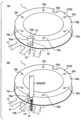
도 4는 이너 하우징의 모터측에 배선을 수납하기 전의 상태를 도시하는 전동기의 요부 사시도이다.
도 5는 이너 하우징의 모터측에 배선을 수납한 후의 상태를 도시하는 전동기의 요부 사시도이다.
도 6은 도 5에 도시하는 요부의 모식적인 부분 확대도로서, 수납 전의 배선을 가상선으로 나타낸다.
도 7은 종래 기술의 전동기에 있어서, 이너 하우징에 배선 고정 부재로 배선을 고정했을 때의 상태를 도시하는 도면이다.1 is an axial cross-sectional view of an electric motor according to an embodiment of the present invention.
2 is a perspective view of the main part of the motor, where (a) shows a state before wiring is accommodated in the resolver side of the inner housing, and (b) shows a state after wiring is accommodated in the resolver side of the inner housing. do.
Fig. 3 is a schematic partial enlarged view of the main part shown in Fig. 2, (a) and (b) show a state before housing the wiring in the resolver side of the inner housing, and (c) and (d) show the inner housing. The state after the wiring is housed in the resolver side of the housing is shown.
Fig. 4 is a perspective view of main parts of the motor showing a state before wiring is accommodated in the motor side of the inner housing;
Fig. 5 is a perspective view of the main part of the motor showing a state after wiring is housed in the motor side of the inner housing.
Fig. 6 is a schematic partial enlarged view of the main part shown in Fig. 5, in which wiring before accommodation is indicated by virtual lines.
Fig. 7 is a diagram showing a state in which wires are fixed to an inner housing with a wire fixing member in a conventional electric motor.
이하, 본 발명의 전동기의 일 실시형태에 대해서, 첨부 도면을 참조하여 설명한다. 단, 본 발명은 이하의 실시형태로 한정되는 것이 아니며, 본 발명의 범위 내에서 설계 변경 가능하다.EMBODIMENT OF THE INVENTION Hereinafter, one embodiment of the electric motor of this invention is described with reference to accompanying drawings. However, the present invention is not limited to the following embodiments, and design changes are possible within the scope of the present invention.
전동기(1)는 다이렉트 드라이브 방식이며, 도 1에 도시하는 바와 같이 하우징(8)을 갖는다. 전동기(1)는, 하우징(8) 내부에, 모터(전기 부품의 일 예)(42)와, 상기 모터(42)를 회전 가능하게 지지하기 위한 베어링(43)과, 상기 모터(42)의 회전 상태를 검출하기 위한 리졸버(회전 검출기, 전기 부품의 일 예)(44)를 구비하고 있다. 하우징(8)은 이너 하우징(10)과, 아우터 하우징(9)을 갖는다. 전동기(1)는 그 전체 대략적인 형상이 대략 원환상의 구조체로 되어 있다. 다른 실시형태에 있어서, 전동기(1)는 다이렉트 드라이브 방식 이외의 것을 적용 가능하다.The
또한, 전동기(1)는 도 2에 도시하는 바와 같이, 원환상으로 형성된 스테이터(11)를 구비하고 있다. 이너 하우징(10)(하우징(8)의 일부)은 스테이터(11)의 내주측에 배치되며, 원환상으로 형성되어 있다. 또한, 스테이터(11)를 권회하는 코일(전기 부품의 일 예)(41)을 보호하기 위해서, 전동기(1)는 스테이터(11)의 상부에 원환상의 원판 부재로 이루어지는 모터 커버(40)를 갖고 있다(도 1 참조).Further, the
또한, 도 2에서는 본 원의 특징 구성의 이해를 용이하게 하기 위해, 모터 커버(40) 및 코일(41)에 대해서, 도시를 생략하고 있다. 후술의 도 4 및 도 5에 있어서도 마찬가지이다.In addition, in FIG. 2, illustration is abbreviate|omitted about the
이너 하우징(10)의 모터 장착면(축단면)(10b)에는, 복수의 장착 구멍(탭 구멍)(10c)이 마련되어 있다. 한편, 전동기(1)가 고정되는 모터 장착 베이스(도시하지 않음)에는, 각 장착 구멍(10c)에 대응하도록 볼트 삽입 구멍이 마련되어 있다. 전동기(1)는 이들 장착 구멍(10c) 및 볼트 삽입 구멍을 이용하여, 볼트에 의해 모터 장착 베이스에 고정되어 있다.The motor mounting surface (shaft end surface) 10b of the
이너 하우징(10)의 외주면에는 도 1에 도시하는 바와 같이, 오목부(움푹부(hollow), 절결, 배선 수용부, 배선 수용 공간(10a, 10d)이 마련되어 있다. 일 실시형태에 있어서, 이너 하우징(10)의 외주면에 있어서의 점대칭의 위치에 2개소에 오목부(10a, 10d)가 마련되어 있다. 다른 실시형태에 있어서, 대체적 및/또는 추가적으로 하우징(8)의 다른 개소에 오목부(움푹부)를 마련할 수 있다. 또한, 오목부의 수는 1, 2, 3, 4, 또는 5 이상으로 할 수 있다.As shown in Fig. 1, the outer circumferential surface of the
오목부(10a, 10d)는 이너 하우징(10)의 (상단면인) 모터 장착면(10b)으로부터 축방향을 따라서(지면 하방을 향하여) 절결된 세로 구멍으로서, 그 단면(횡단면)은 외주측이 개방된 U자형상을 갖는다.The
오목부(제 1 오목부)(10a)는 회전 위치 검출용으로서 리졸버(44)에 접속되는 배선 부재(20a)(리졸버선이라고도 함)의 수납부로서 이용된다(도 2 참조). 오목부(제 2 오목부)(10d)는 전력 급전용으로서의 스테이터(11)의 코일(41)에 접속되는 배선 부재(20b)(모터선이라고도 함)의 수납부로서 이용된다. 다른 실시형태에 있어서, 하우징(8)에 수용되는 다른 전기 부품에 접속되는 배선 부재의 수납부로서, 다른 오목부를 마련할 수 있다.The concave portion (first concave portion) 10a is used as a receiving portion for a
이와 같이 오목부(10a, 10d)에 배선 부재(20a, 20b)가 수납되는 것에 의해, 이너 하우징(10)의 외주면으로부터 배선 부재(20a, 20b)가 삐져나오지 않아, 스테이터(11)와 접촉할 우려가 없어진다.As the
이하, 본 실시형태에 있어서의 리졸버선측의 이너 하우징의 형태, 배선 고정 부재, 모터선측의 이너 하우징의 형태에 대해서 순서대로 설명한다.Hereinafter, the form of the inner housing on the resolver ship side, the wiring fixing member, and the form of the inner housing on the motor ship side in this embodiment will be described in order.
[리졸버선측의 이너 하우징][Inner housing on resolver line side]
오목부(10a)는 이너 하우징(10)의 상단면(모터 장착면(10b))으로부터 축방향으로 절결된 세로 구멍이다. 오목부(10a)의 하단부는 관통 구멍(13)과 연결되어 있다. 관통 구멍(13)은 이너 하우징(10)의 하단면으로부터 축방향을 따라서(지면 상방을 향하여) 형성된 관로이다. 관통 구멍(13)의 내부에 리드선(14)을 삽통하는 것이 가능하다(도 1 참조).The
또한, 오목부(10a)(움푹부, U자 구멍)의 상세한 형상에 대해서는, 후술하는 배선 고정 부재(2)(피걸림고정부)와 오목부(10a)(걸림고정부)의 관계의 설명에서 함께 설명한다. 여기에서는, 특히, 모터선측의 이너 하우징과 상이한 부분에 대해서 설명한다.Regarding the detailed shape of the
모터(1)에서는, 리졸버(44)가 베어링(43)의 하방측(이너 하우징(10)의 외주 저면)에 마련되어 있다. 리드선(케이블선)(14)이 이너 하우징(10) 내부에 마련된 1개의 원통형상의 관통 구멍(관로)(13)에 삽통되며, 리졸버(44)와 외부의 센서 장치가 리드선(14)을 거쳐서 전기적으로 접속되어 있다.In the
관통 구멍(관로)(13)은 리드선(14)의 다발을 삽통할 수 있도록, 리드선(14)의 다발의 직경보다 동일한 정도 또는 큰 직경을 갖는다. 관통 구멍(관로)(13)의 일단(기단)은 세로 구멍(오목부(10a))의 하단부와 연결되며, 도중 이너 하우징(10) 내를 축방향을 따라서 관통한다. 관통 구멍(관로)(13)의 타단(말단)은 이너 하우징(10)의 하단면에 형성되며, 리드선(14)을 관통 구멍(13)으로부터 인출하는 것이 가능한 개구(16)로 되어 있다.The through hole (conduit) 13 has a diameter equal to or larger than the diameter of the bundle of
본 실시형태에서는, 리졸버(44)의 위치를 이너 하우징(10)의 저면측에 구비하는 형태로 하고 있다. 다른 실시형태에 있어서, 예를 들면, 리졸버(44)를 이너 하우징(10)의 상면측에 구비하는 형태의 경우에는, 축방향으로 전체에 걸쳐서 관통 구멍(13)을 마련할 필요는 없다. 예를 들면, 도 2의 (b)에 도시하는 바와 같이 오목부(10a)에 형성되어 있는 간극(배선 고정 부재(2)로부터 오목부(10a) 저면까지의 공간(10h))에 리드선(14)을 당겨서 배선하는 형태로 하여도 좋다.In this embodiment, the position of the
리드선(14)은 외부 환경으로부터 보호하기 위해서, 외부의 센서 장치로 인출되는 부분을 예를 들면, 폴리염화비닐(PVC) 등의 가요성의 튜브를 이용하여, 복수의 리드선(14)의 일부 외주측을 덮도록 구성되어 있다. 다른 실시형태에 있어서, 리드선(14)은 다른 재료의 가요성 튜브를 이용한 형태, 또는 가요성의 튜브를 이용한 형태와는 상이한 형태를 적용할 수 있다.In order to protect the
[배선 부재][wiring member]
배선 부재(20a, 20b)는 배선 부재(20a, 20b)의 외면에 마련된 배선 고정 부재(2)를 갖고 있다. 배선 고정 부재(2)는 배선 부재(20a, 20b)의 축방향을 따른 소정의 축 길이와 직경방향 두께를 갖는 원환상 부재이다. 예를 들면, 배선 고정 부재(2)는 배선 부재(20a, 20b)의 튜브(20)의 외주에 접착되어, 튜브(20)와 일체화되어 있다. 배선 고정 부재(2)의 외경은 배선 부재(20a, 20b)에 비해 크다. 배선 고정 부재(2)의 축단(피걸림고정부(21))은 배선 부재(20a, 20b)의 외주면에 대해서 직경방향 외측으로 돌출된 상태로 배치된다. 다른 실시형태에 있어서, 배선 고정 부재(2)는 원환상 이외의 형상을 가질 수 있다.The
본 실시형태에서는, 오목부(10a, 10d)는 도 2의 (a) 및 도 3에 도시하는 바와 같이 걸림고정부(12)를 갖고 있다. 걸림고정부(12)는 배선 부재(20a, 20b)를 오목부(U자 구멍)(10a, 10d)의 내주면(벽면(18))에 마련된 단차로서, 단면에서 보아 U자형상으로 형성되어 있다. 이와 같은 오목부(10a, 10d)의 단차에 배선 고정 부재(2)가 걸려져 고정된다. 오목부(움푹부)(10a, 10d)는 배선 부재(20a, 20b)의 축방향(하우징(8)의 축방향)을 따라서 연장되어서 마련된다. 오목부(움푹부)(10a, 10d)는 배선 부재(20a, 20b)의 일부 및 배선 고정 부재(2)를 둘러싸는 벽면(18)을 갖는다. 벽면(18)에는 배선 부재(20a, 20b)의 축방향(하우징(8)의 축방향)에 있어서의 배선 고정 부재(2)의 움직임을 제한하는 걸림고정부(스토퍼, 단차(level difference), 앵커, 후크)(12)가 마련된다. 걸림고정부(스토퍼)(12)는 벽면(18)에 대해서 돌출되어서 마련된다. 일 예에 있어서, 배선 고정 부재(2)의 축단(피걸림고정부(21))이 걸림고정부(스토퍼)(12)에 접촉되어서 배치된다.In this embodiment, the
구체적으로는, 배선 부재(20a, 20b)를 오목부(U자 구멍)(10a, 10d) 내에 압입하면, 배선 고정 부재(2)의 튜브(20)로부터 직교하는 방향으로 플랜지형상으로 돌출된 영역이 피걸림고정부(21)로서 기능하며, 배선 부재(20a, 20b)는 걸림고정부(12)와 끼워맞추어져 고정된다. 튜브(20)의 그 이상의 이동은 저지되기 때문에, 배선 부재(20a, 20b)의 빠짐을 방지할 수 있다. 배선 고정 부재(2)의 단부(피걸림고정부(21))가 걸림고정부(스토퍼)(12)에 접촉되어, 배선 부재(20a, 20b) 및 배선 고정 부재(2)의 축방향의 움직임이 제한된다. 오목부(10a)에 있어서, 걸림고정부(12)의 단면(접촉면)과 저면(10h) 사이의 거리는, 배선 고정 부재(2)의 축 길이와 동일한 정도, 또는 배선 고정 부재(2)의 축길이 보다도 크다.Specifically, when the
일 예에 있어서, 배선 고정 부재(2)(피걸림고정부(21))는 수지제이다. 다른 예에 있어서, 배선 고정 부재(2)는 금속제 등 수지제 이외라도 좋다.In one example, the wiring fixing member 2 (the part to be caught 21) is made of resin. In another example, the
다른 실시형태에 있어서, 하우징(8)의 벽면(18)에 오목부(걸림고정부(12))가 마련되며, 배선 고정 부재(2)에 볼록부(피걸림고정부(21))가 마련되며, 오목부(걸림고정부(12))와 볼록부(피걸림고정부(21))가 서로 맞물리는 구조로 할 수 있다. 혹은, 하우징(8)의 벽면(18)에 볼록부(걸림고정부(12))가 마련되며, 배선 고정 부재(2)에 오목부(피걸림고정부(21))가 마련되며, 볼록부(걸림고정부(12))와 오목부(피걸림고정부(21))가 서로 맞물리는 구조로 할 수 있다. 일 예에 있어서, 피걸림고정부(21)는 요철(클로부)의 끼워맞춤으로, 걸림고정부(12)와 맞물리는 구조로 하여도 좋다. 예를 들면, 배선 고정 부재(2)(피걸림고정부(21))의 외주면에 오목부(U자 구멍)(10a)의 개구측 내주면에 마련한 오목부와 끼워맞추는 볼록부를 마련하는 구조(래치 구조, 로크 구조, 탄성체를 이용한 맞물림 구조)로 하여도 좋다. 반대로, 배선 고정 부재(2)(피걸림고정부(21))의 외주면에 오목부를 오목부(U자 구멍)(10a)의 내주면에 볼록부를 마련하고 끼워맞춤으로 맞물리는 구조(래치 구조, 로크 구조, 탄성체를 이용한 맞물림 구조)로 하여도 좋다.In another embodiment, a concave portion (locking portion 12) is provided on the
일 예에 있어서, 도 3의 (a) 및 (b)에 도시하는 바와 같이, 오목부(U자 구멍)(10a)는 이너 하우징(10)의 축방향으로 길이(T2)를 갖는 공간부를 갖는다. 그 공간부에 면하는 벽면(18)의 직경방향 내측의 영역에, 튜브(20)의 외경(S1)과 피걸림고정부(21)의 외경(S2)의 차분(P)((S2-S1)/2)과 동일한 정도의 단차가 형성되어 있다. 이 단차 부분이 걸림고정부(12)로서 마련되어 있다. 오목부(10a)(공간부)는 직경방향을 따른 제 1 깊이(T1)와, 제 1 깊이(T2)에 비해 작은 제 2 깊이(T3)를 갖는다.In one example, as shown in (a) and (b) of FIG. 3 , the concave portion (U-shaped hole) 10a has a space portion having a length T2 in the axial direction of the
걸림고정부(12)는 오목부(U자 구멍)(10a) 내에, 배선 고정 부재(2)의 일부를 수납 가능한 공간을 형성하도록 마련되어 있다. 일 예에 있어서, 도 3의 (a) 및 (b)에 도시하는 바와 같이, 제 1 U자 구멍(12a)과 제 2 U자 구멍(12b)이 형성되어 있다. 제 2 U자 구멍(12b)은 제 1 U자 구멍(12a)의 곡면에 대해서 축심에 근접하여 마련된 곡면을 갖는다. 예를 들면, 제 2 U자 구멍(12b)의 곡면은 피걸림고정부(21)의 외주면을 따른 윤곽을 갖는다. 제 1 U자 구멍(12a)과 제 2 U자 구멍(12b)의 깊이의 차분(P)이 걸림고정부(12)로서의 단차이다. 이 단차의 돌출의 정도(차분(P))는 배선 고정 부재(2)의 플랜지의 돌출 정도에 대응하고 있다.The locking
이어서, 배선 고정 부재(2)의 고정 방법에 대해서, 도 3의 (a) 내지 (d)를 이용하여 설명을 한다. 도 3의 (a) 및 (b)는 장착 전의 상태를 도시한다. 도 3의 (c) 및 (d)는 장착 후 상태를 도시한다. 도 3의 (c) 및 (d)에 있어서, 배선 고정 부재(2)의 피걸림고정부(21)가 걸림고정부(12)의 차분(P)의 단차에 걸려, 배선 고정 부재(2)가 이너 하우징(10)에 장착되어 있다. 즉, 피걸림고정부(21)와 걸림고정부(12)가 끼워맞추어져 고정되어 있다.Next, the fixing method of the
배선 고정 부재(2)의 고정 방법은 예를 들면, 도 3의 (a) 및 (b)에 도시하는 장착 전의 상태로부터, 배선 고정 부재(2)를 오목부(10a)의 축 중심을 향하여 압입한다. 그 때, 도 3의 (c) 및 (d)에 도시하는 상태가 되도록, 제 1 U자 구멍(12a)과 제 2 U자 구멍(12b)의 경계에 있는 단차의 하면(축 단면)과, 배선 고정 부재(2)의 플랜지부(피걸림고정부(21))의 상면(축 단면)이 접촉하도록 배선 고정 부재(2)를 오목부(10a)에 압입한다.The fixing method of the
이 구성에 의해, 이너 하우징(10)에 대해서 배선 고정 부재(2)가 안정적으로 보지된다.With this configuration, the
또한, 배선 고정 부재(2)를 오목부(10a)에 고정할 때에, 튜브(20)를 가압하는 일이 없으므로, 튜브(20)에 무리한 힘이 가해져 손상될 우려가 없다.Further, since the
일 예에 있어서, 피걸림고정부(21)의 외경(S2)과, 이너 하우징(10)의 제 2 U자 구멍(12b)(제 1 U자 구멍(12a))의 폭은 대략 동일하다. 피걸림고정부(21)(배선 고정 부재(2))의 소재가 수지제인 경우, 피걸림고정부(21)를 강하게 압입하는 것에 의해, 제 2 U자 구멍(12b)을 따라서 피걸림고정부(21)가 탄성 변형되고, 제 2 U자 구멍(12b)에 있어서 피걸림고정부(21)와 걸림고정부(12)가 끼워맞추어진다. 다른 예에 있어서, 피걸림고정부(21)(배선 고정 부재(2))의 소재를 수지 이외의 재료로 할 수 있다. 피걸림고정부(21)의 외경(S2)은 이너 하우징(10)의 제 2 U자 구멍(12b)(제 1 U자 구멍(12a))의 폭에 비해 작게 설정할 수 있다. 이 경우, 배선(20a, 20b)의 유연성 등의 특성에 따라서, 배선 고정 부재(2)의 이동이 억제되도록 오목부(10a)에 있어서의 걸림고정부(12)의 단면과 저면(10h) 사이의 거리와, 배선 고정 부재(2)의 축 길이의 관계가 설정된다.In one example, the outer diameter S2 of the part to be caught 21 and the width of the second
피걸림고정부(21)와 걸림고정부(12)가 끼워맞추어져 고정되면, 배선 고정 부재(2)가 이너 하우징(10)으로부터 이격되는 방향, 즉, 배선 부재(20a, 20b)가 축방향 상방으로 인장되어도 피걸림고정부(21)가 걸림고정부(12)에 걸린다. 그 때문에, 배선 고정 부재(2)의 축방향의 이동이 저지되어, 배선 부재(20a, 20b)의 보지 상태가 유지된다. 이에 의해, 배선 구조는 배선 부재(20a, 20b)가 탈락하지 않아, 높은 신뢰성을 갖는다.When the hooked fixing
도 3에 도시하는 바와 같이, 이너 하우징(10)(하우징(8))의 벽면(18)은 튜브(배선 부재(20a, 20b))(20)의 축 주위의 둘레방향(오목부(10a)의 축 주위의 둘레방향)에 있어서, 제 1 구간(SC1), 제 2 구간(SC2), 제 3 구간(SC3) 및 제 4 구간(SC4)을 갖는다. 제 1 구간(SC1)에 있어서, 벽면(18)에 걸림고정부(스토퍼)(12)가 마련되어 있다. 제 2 구간(SC2)에 있어서, 오목부(움푹부)(10a)가 개방되어 있다(벽면(18)이 없는 영역). 제 3 구간(SC3) 및 제 4 구간(SC4)은 걸림고정부(스토퍼)(12)의 비형성 영역(걸림고정부(12)가 없는 영역)으로서, 둘레방향에 있어서의 제 1 구간(SC1)과 제 2 구간(SC2) 사이에 배치된다. 제 1 구간(SC1)은 이너 하우징(10)의 직경방향 내측에 배치되며, 제 2 구간(SC2)은 직경방향 외측에 배치된다. 개방 영역인 제 2 구간(SC2)을 거쳐서, 하우징(8)(이너 하우징(10))에 대해서 배선 부재(20a, 20b) 및 배선 고정 부재(2)의 장착 작업이 원활히 실행된다. 제 3 구간(SC3)의 벽면(18)과 제 4 구간(SC4)의 벽면(18)이 서로 대향하여 배치된다. 예를 들면, 제 3 구간(SC3)의 벽면(18)과, 제 4 구간(SC4)의 벽면(18)이 서로 대략 평행하게 배치된다. 혹은, 제 3 구간(SC3)의 벽면(18)과 제 4 구간(SC4)의 벽면(18)이 직경방향을 따라서 서로의 거리가 서서히 변화하도록 배치된다. 장착 또는 분리 작업시에 배선 부재(20a, 20b) 및 배선 고정 부재(2)가 제 3 및 제 4 구간(SC3, SC4)의 벽면(18)에 안내되어, 작업이 원활히 실행된다.As shown in FIG. 3, the
여기에서, 다이렉트 드라이브 모터(이하, 전동기라 함)는 기어나 벨트 및 롤러 등의 전달 기구를 개재시키는 일이 없이, 회전체에 회전력을 다이렉트로 전달하고, 상기 회전체를 피회전체에 대해서 소정방향으로 회전시키는 구동 방식(모터 부하 직결형의 구동 방식)을 채용하며, 공작 기기의 워크 회전 보지부 및 로봇의 구동 관절부 등에 이용되고 있다.Here, the direct drive motor (hereinafter referred to as an electric motor) directly transmits rotational force to the rotating body without intervening transmission mechanisms such as gears, belts and rollers, and moves the rotating body in a predetermined direction with respect to the rotating body. It adopts a drive method (motor load direct drive type) that rotates with a motor load, and is used for workpiece rotation holding parts of machine tools and drive joints of robots.
이런 종류의 전동기로서는, 부하를 직접 구동하는 장치의 외형은 가능한 한 작게 하는 한편, 한정된 용적 내에서 전동기 출력(모터 출력)을 가능한 한 크게 하기 위해서, 모터 출력에 직접 기여하지 않는 하우징이나 배선의 인출부를 가능한 한 작게 하는 것이 요구된다.With this type of motor, in order to make the external shape of the device that directly drives the load as small as possible, while increasing the motor output (motor output) as much as possible within a limited volume, the housing or wiring that does not directly contribute to the motor output is drawn out. It is required to keep the wealth as small as possible.
본 실시형태의 전동기(1)에 의하면, 종래 기술의 전동기와 같이 볼트 삽입 구멍을 마련하고, 배선 고정 부재를 볼트로 금구를 고정하는 구조는 아니기 때문에, 볼트나 금구 등 부품 점수를 줄일 수 있어서, 염가로 실현할 수 있다. 또한, 볼트나 금구 등 부품을 마련하는 공간을 생략할 수 있기 때문에, 제품 전체를 컴팩트하게 할 수 있다. 또한, 부품 점수가 적기 때문에, 배선 고정 부재 등의 장착 작업의 효율을 높일 수 있다. 또한, 종래 기술의 전동기와 같이 배선 고정 부재를 볼트로 금구를 고정하는 구조는 아니기 때문에, 배선이 인장되는 힘이 가해졌을 때에 금구가 느슨해져, 금구나 볼트 등 부품이 모터 회전 부분에 낙하할 우려가 없다.According to the
[모터선측의 이너 하우징][Inner housing on the motor ship side]
다음에, 모터선측의 이너 하우징의 형태에 대해서, 도 4 및 도 5를 참조하여 설명한다.Next, the shape of the inner housing on the motor ship side will be described with reference to FIGS. 4 and 5 .
도 4 및 도 5에 있어서, 오목부는 이너 하우징(10)의 한쪽의 단면(모터 장착면(10b))으로부터 축방향으로 절결된 세로 구멍의 오목부(10d)와, 세로 구멍의 오목부(10d)와 연통되며, 이너 하우징(10)의 외주면을 따라서 절결된 가로 구멍의 오목부(10e)로 이루어지는 전체 역 T자형상의 절결 구멍을 갖는다.4 and 5, the concave portion is a vertical hole
세로 구멍의 오목부(10d)와 배선 고정 부재(2)의 관계에 대해서는, 앞에서 설명한 리졸버선측의 오목부(10a)(걸림고정부)와 배선 고정 부재(2)의 관계와 마찬가지이기 때문에, 여기에서의 설명은 간략화한다. 이하에서는, 특히, 이너 하우징(10)의 리졸버선측의 형태와 상이한 부분을 중심으로 설명한다.The relationship between the
전동기(1)의 모터(42)는 이너 하우징(10)의 외측에서 베어링(43)보다 축방향 상측의 위치에 구비되어 있기 때문에, 리졸버선측과 같이(상기 리졸버선을 배선하기 위한) 관통 구멍(13)은 형성되어 있지 않다.Since the
모터측의 이너 하우징(10)에는, 상술한 바와 같이, 도 4 및 도 5에 도시하는 바와 같이, 오목부(10a)와 점대칭의 위치에 있는 오목부(10d)와, 외주면의 일부를 둘레방향을 따라서 절결된 오목부(10e)가 형성되며, 축방향을 따라서 외주면 도중까지 연장된 세로 구멍인 오목부(10d)와(측방으로부터의), 단면에서 보아 원호형상의 절결인 가로 구멍의 오목부(10e)는 연통되며, 전체로 T자형상으로 형성되어 있다.As described above, in the
가로 구멍의 오목부(10e)는 도 6에 도시하는 바와 같이, 모터(42)의 축심을 중심으로 한 각도(α)의 범위로 절결되어 있다. 이 각도(α)의 범위는 전동기 제품이나 설치 상황 등에 따라서 적절히 설정되어 있다.As shown in FIG. 6 , the
또한, 오목부(10e)는 절결 깊이(Q1)의 위치에 외주면으로부터 절취된 원호(10f)와 현(10g)에 의해서 둘러싸인 공간 영역(수평방향)이 형성되어 있다. 그 때의 내경은 도면부호 Q2이다. 본 실시형태에서는, 깊이(Q1)는 도 3의 (a)에 도시하는 이너 하우징(10)의 축심방향(도면에서는 세로방향)으로 깊이(T1)와 동일한 깊이의 위치이다.Further, in the
세로 구멍의 오목부(10d)에는, (리졸버선측의) 오목부(10a)와 마찬가지로, 직경방향으로 소정 폭을 갖고서 걸림고정부(12)(단차)가 돌출 형성되어 있다. 또한, 이 오목부(10d)에 압입되는 배선 고정 부재(2)의 구성도 동일하다.In the
즉, 배선(20b)은 걸림고정부(12)의 하면과 배선 고정 부재(2)(피걸림고정부(21))의 상면이 접촉된 상태에서 걸림고정부(12)에 걸림고정된다.That is, the
본 실시형태에서는, 리드선(15)이 오목부(10e)에 수납되어 있으며, 원호형상의 현(10g)을 따라서 좌우 두 조로 나누어져, 각각 모터(42)의 코일(41)과 접속되어 있다.In this embodiment, the
또한, 리드선(15)은 전동기 제품이나 설치 상황에 따라서 배선되므로, 반드시 좌우 두 조 방향으로만 나뉜다고는 할 수 없다. 예를 들면, 리드선(15)을 일방향, 혹은 두 조보다 많이 나누는 형태라도 좋다. 또한, 오목부(10e)의 절결의 각도(α)의 범위 내에서 다양한 방향으로 배선하는 형태라도 좋다.In addition, since the
이상과 같이, 배선 부재(20b)의 수납부로서, 이너 하우징(10)에 오목부(10d, 10e)를 마련하는 것에 의해, 리드선(15)을 전동기(1)의 스테이터의 위치 구조에 적응시켜 배선하는 것이 가능해진다. 또한, 리드선(15)을 이너 하우징(10)의 외경으로부터는 삐져나오는 일이 없이 보지할 수 있으므로, 전동기(1)를 보다 컴팩트하게 구성하는 것이 가능하다. 또한, 종래와 같이 배선을 고정하기 위한 금구 등도 불필요하기 때문에, 배선의 장착 작업시의 효율을 높일 수 있다.As described above, by providing the
1: 전동기(다이렉트 드라이브 모터)2: 배선 고정 부재
10: 이너 하우징10a, 10d: 오목부(세로 구멍)
11: 스테이터12: 걸림고정부(단차)
13: 관통 구멍14, 15: 리드선
16: 개구부20: 튜브
20a, 20b: 배선 부재21: 피걸림고정부
40: 모터 커버41: 코일
42: 모터43: 베어링
44: 리졸버1: electric motor (direct drive motor) 2: wiring fixing member
10:
11: stator 12: locking part (step difference)
13: through
16: opening 20: tube
20a, 20b: Wiring member 21: Caught fixing part
40: motor cover 41: coil
42: motor 43: bearing
44: resolver
Claims (13)
Translated fromKorean스테이터의 내주측에 배치되는 환상의 이너 하우징과,
상기 배선 부재의 주위에 형성된 배선 고정 부재를 가지며,
상기 이너 하우징의 외주연부에는, 일단면에 개구되며 축방향으로 연장된 세로 구멍이 형성되며,
상기 세로 구멍의 내주면에는 단차가 형성되며,
상기 배선 부재는, 상기 세로 구멍에 삽통되었을 때에, 상기 배선 고정 부재가 상기 단차에 걸림고정되어, 상기 이너 하우징으로부터 빠지는 것을 방지하고,
상기 배선 고정 부재는 수지제이고,
상기 배선 고정 부재가 탄성 변형되도록 상기 배선 고정 부재가 상기 세로 구멍에 압입됨으로써, 상기 배선 고정 부재와 상기 세로 구멍이 끼워맞춰지는 것을 특징으로 하는
전동기.a wiring member,
An annular inner housing disposed on the inner circumferential side of the stator;
a wiring fixing member formed around the wiring member;
A vertical hole opened at one end surface and extending in the axial direction is formed on the outer circumferential edge of the inner housing,
A step is formed on the inner circumferential surface of the vertical hole,
When the wiring member is inserted into the vertical hole, the wiring fixing member is caught and fixed to the step and prevents it from coming out of the inner housing;
The wiring fixing member is made of resin,
The wire fixing member is press-fitted into the vertical hole so that the wire fixing member is elastically deformed, so that the wire fixing member and the vertical hole are fitted.
electric motor.
상기 세로 구멍은 단면 U자형상으로 형성되어 있으며,
상기 세로 구멍의 상기 단차는, 상기 이너 하우징에 대해서 상기 축방향에 있어서의 외측방향으로의 상기 배선 고정 부재의 움직임을 제한하는 것을 특징으로 하는
전동기.According to claim 1,
The vertical hole is formed in a U-shape in cross section,
The step of the vertical hole limits the movement of the wiring fixing member in the axial direction outward with respect to the inner housing.
electric motor.
상기 배선 고정 부재는 상기 배선 부재의 외주로부터 돌출된 플랜지인 것을 특징으로 하는
전동기.According to claim 1 or 2,
Characterized in that the wiring fixing member is a flange protruding from the outer circumference of the wiring member
electric motor.
상기 배선 고정 부재는 가요성을 갖는 것을 특징으로 하는
전동기.According to claim 1 or 2,
The wire fixing member is characterized in that it has flexibility
electric motor.
스테이터의 내주측에 배치되는 환상의 이너 하우징과,
상기 배선 부재의 주위에 형성된 배선 고정 부재를 가지며,
상기 이너 하우징의 외주연부에는, 일단면에 개구되며 축방향으로 연장된 세로 구멍이 형성되며,
상기 세로 구멍의 내주면에는 단차가 형성되며,
상기 배선 부재는, 상기 세로 구멍에 삽통되었을 때에, 상기 배선 고정 부재가 상기 단차에 걸림고정되어, 상기 이너 하우징으로부터 빠지는 것을 방지하고,
상기 이너 하우징의 측면에는, 둘레방향을 따라서 절결되며 또한 상기 축방향과 교차하는 방향으로 연장된 가로 구멍이 형성되며,
상기 세로 구멍과 상기 가로 구멍이 연통되며,
상기 세로 구멍과 상기 가로 구멍이 연통된 개소에 있어서 상기 배선 부재가 나눠지며,
상기 배선 부재의 일부가 상기 가로 구멍의 제 1 부분에서 연장되어서 배치되고,
상기 배선 부재의 다른 일부가, 상기 제 1 부분과 상이한 상기 가로 구멍의 제 2 부분에서 연장되어서 배치되는 것을 특징으로 하는
전동기.a wiring member,
An annular inner housing disposed on the inner circumferential side of the stator;
a wiring fixing member formed around the wiring member;
A vertical hole opened at one end surface and extending in the axial direction is formed on the outer circumferential edge of the inner housing,
A step is formed on the inner circumferential surface of the vertical hole,
When the wiring member is inserted into the vertical hole, the wiring fixing member is caught and fixed to the step and prevents it from coming out of the inner housing;
A side surface of the inner housing is formed with a horizontal hole cut along the circumferential direction and extending in a direction crossing the axial direction,
The vertical hole and the horizontal hole communicate,
The wiring member is divided at a location where the vertical hole and the horizontal hole communicate with each other,
A portion of the wiring member is disposed extending from the first portion of the horizontal hole,
characterized in that another part of the wiring member is disposed extending from a second part of the horizontal hole different from the first part
electric motor.
다이렉트 드라이브 방식인 것을 특징으로 하는
전동기.According to claim 1 or 2,
Characterized in that it is a direct drive method
electric motor.
상기 하우징에 수용되는 전기 부품에 접속되는 배선 부재와,
상기 배선 부재의 외면에 마련된 배선 고정 부재를 구비하며,
상기 하우징은,
상기 배선 부재의 축방향을 따라서 연장되어서 마련되며, 상기 배선 부재의 일부 및 상기 배선 고정 부재를 둘러싸는 벽면을 갖는 움푹부와,
상기 벽면에 마련되며, 상기 배선 고정 부재의 상기 축방향의 움직임을 제한하는 스토퍼를 갖고,
상기 배선 고정 부재는 수지제이고,
상기 배선 고정 부재가 탄성 변형되도록 상기 배선 고정 부재가 상기 움푹부에 압입됨으로써, 상기 배선 고정 부재와 상기 움푹부가 끼워맞춰지는
전동기.housing department,
a wiring member connected to an electric component accommodated in the housing;
A wiring fixing member provided on an outer surface of the wiring member,
the housing,
a recess extending along the axial direction of the wiring member and having a wall surface surrounding a portion of the wiring member and the wiring fixing member;
a stopper provided on the wall surface and limiting movement of the wire fixing member in the axial direction;
The wiring fixing member is made of resin,
The wire fixing member is press-fitted into the dent so that the wire fixing member is elastically deformed, so that the wire fixing member and the dent are fitted.
electric motor.
상기 스토퍼는 상기 벽면에 대해서 돌출되어서 마련되는
전동기.According to claim 7,
The stopper is provided by protruding with respect to the wall surface
electric motor.
상기 배선 고정 부재는 상기 축방향에 있어서, 상기 하우징의 일단면과 상기 전기 부품 사이에 위치하는
전동기.According to claim 8,
The wire fixing member is located between one end surface of the housing and the electrical component in the axial direction.
electric motor.
상기 벽면은, 소정의 둘레방향에 있어서, 상기 벽면에 상기 스토퍼가 부분적으로 마련된 제 1 구간과, 상기 움푹부가 개방된 제 2 구간을 갖는
전동기.According to claim 8 or 9,
The wall surface has, in a predetermined circumferential direction, a first section in which the stopper is partially provided on the wall surface, and a second section in which the recess is open.
electric motor.
상기 하우징에 수용되는 전기 부품에 접속되는 배선 부재와,
상기 배선 부재의 외면에 마련된 배선 고정 부재를 구비하며,
상기 하우징은,
상기 배선 부재의 축방향을 따라서 연장되어서 마련되며, 상기 배선 부재의 일부 및 상기 배선 고정 부재를 둘러싸는 벽면을 갖는 움푹부와,
상기 벽면에 마련되며, 상기 배선 고정 부재의 상기 축방향의 움직임을 제한하는 스토퍼를 갖고,
상기 스토퍼는 상기 벽면에 대해서 돌출되어서 마련되며,
상기 배선 고정 부재가 탄성 변형되도록 상기 배선 고정 부재가 상기 움푹부에 압입되어 있고,
상기 벽면은, 소정의 둘레방향에 있어서, 상기 벽면에 상기 스토퍼가 부분적으로 마련된 제 1 구간과, 상기 움푹부가 개방된 제 2 구간을 갖고,
상기 벽면은, 상기 소정의 둘레방향에 있어서의 상기 제 1 구간과 상기 제 2 구간 사이에 배치되며 또한 상기 스토퍼의 비형성 영역인 제 3 구간 및 제 4 구간을 가지며,
상기 제 3 구간의 상기 벽면과 상기 제 4 구간의 벽면이 서로 대향하여 배치되는
전동기.housing department,
a wiring member connected to an electric component accommodated in the housing;
A wiring fixing member provided on an outer surface of the wiring member,
the housing,
a recess extending along the axial direction of the wiring member and having a wall surface surrounding a portion of the wiring member and the wiring fixing member;
a stopper provided on the wall surface and limiting movement of the wire fixing member in the axial direction;
The stopper is provided to protrude from the wall surface,
the wire fixing member is press-fitted into the recess so that the wire fixing member is elastically deformed;
The wall surface has, in a predetermined circumferential direction, a first section in which the stopper is partially provided on the wall surface and a second section in which the recess is open;
The wall surface is disposed between the first section and the second section in the predetermined circumferential direction and has a third section and a fourth section, which are non-formed regions of the stopper,
The wall surface of the third section and the wall surface of the fourth section are disposed to face each other.
electric motor.
상기 배선 고정 부재의 축단면과 상기 움푹부의 바닥면 사이에 상기 축방향의 간극이 마련되어 있는
전동기.According to claim 8 or 9,
The axial gap is provided between the axial end surface of the wire fixing member and the bottom surface of the recessed portion.
electric motor.
Applications Claiming Priority (3)
| Application Number | Priority Date | Filing Date | Title |
|---|---|---|---|
| JP2017178756 | 2017-09-19 | ||
| JPJP-P-2017-178756 | 2017-09-19 | ||
| PCT/JP2018/024495WO2019058690A1 (en) | 2017-09-19 | 2018-06-28 | Electric motor |
Publications (2)
| Publication Number | Publication Date |
|---|---|
| KR20200057702A KR20200057702A (en) | 2020-05-26 |
| KR102564076B1true KR102564076B1 (en) | 2023-08-04 |
Family
ID=65810712
Family Applications (1)
| Application Number | Title | Priority Date | Filing Date |
|---|---|---|---|
| KR1020207005975AActiveKR102564076B1 (en) | 2017-09-19 | 2018-06-28 | electric motor |
Country Status (6)
| Country | Link |
|---|---|
| US (1) | US20200161925A1 (en) |
| JP (1) | JP6579280B2 (en) |
| KR (1) | KR102564076B1 (en) |
| CN (2) | CN111052556B (en) |
| TW (1) | TWI780170B (en) |
| WO (1) | WO2019058690A1 (en) |
Families Citing this family (4)
| Publication number | Priority date | Publication date | Assignee | Title |
|---|---|---|---|---|
| JP2020167908A (en)* | 2019-03-29 | 2020-10-08 | 日本電産株式会社 | motor |
| CN111585400B (en)* | 2020-06-24 | 2022-10-04 | Abb瑞士股份有限公司 | Servo motor and assembling method thereof |
| JP7643072B2 (en)* | 2021-02-19 | 2025-03-11 | ニデック株式会社 | Motor |
| US12381441B2 (en)* | 2021-02-25 | 2025-08-05 | Regal Beloit America, Inc. | Electric machine assembly having end frame cooling |
Citations (4)
| Publication number | Priority date | Publication date | Assignee | Title |
|---|---|---|---|---|
| JP2005354847A (en) | 2004-06-11 | 2005-12-22 | Nsk Ltd | Rotation drive |
| JP2007244096A (en) | 2006-03-08 | 2007-09-20 | Nsk Ltd | Electric motor |
| JP2008029090A (en)* | 2006-07-19 | 2008-02-07 | Nsk Ltd | Electric motor |
| JP2011136655A (en) | 2009-12-28 | 2011-07-14 | Bridgestone Cycle Co | Bicycle gear shift position detection device and bicycle |
Family Cites Families (12)
| Publication number | Priority date | Publication date | Assignee | Title |
|---|---|---|---|---|
| US4000764A (en)* | 1975-03-27 | 1977-01-04 | The Globe Tool And Engineering Company | Stator lead termination apparatus |
| JPH06233483A (en)* | 1993-01-29 | 1994-08-19 | Honda Motor Co Ltd | Connection structure of coil winding in stator |
| US6100614A (en)* | 1999-01-12 | 2000-08-08 | A. O. Smith Corporation | Electric motor with spring clip for strain relief |
| JP5202181B2 (en)* | 2008-08-18 | 2013-06-05 | アイチエレック株式会社 | Electric motor |
| JP5865767B2 (en)* | 2012-04-09 | 2016-02-17 | 日立オートモティブシステムズ株式会社 | In-vehicle rotating electrical machine and electric power steering device |
| CN203562863U (en)* | 2013-10-10 | 2014-04-23 | 合肥荣事达三洋电器股份有限公司 | External rotor motor wire harness limiting structure |
| JP6368936B2 (en)* | 2014-09-30 | 2018-08-08 | 日本電産株式会社 | motor |
| DE102014220201A1 (en)* | 2014-10-06 | 2016-04-07 | Bühler Motor GmbH | Electronically commutated DC motor, in particular for an oil pump |
| CN204810016U (en)* | 2014-12-11 | 2015-11-25 | 德昌电机(深圳)有限公司 | Rotor, motor, pump and belt cleaning device |
| KR20170084336A (en)* | 2015-01-13 | 2017-07-19 | 미쓰비시덴키 가부시키가이샤 | Electric motor stator and electric motor |
| CN205693470U (en)* | 2016-06-24 | 2016-11-16 | 江苏雷利电机股份有限公司 | A kind of horizontal stage electric machine |
| CN206313569U (en)* | 2016-12-07 | 2017-07-07 | 东莞市骏能电子科技有限公司 | A kind of permanent magnet synchronous motor of the standard specification size that twin voltage is powered |
- 2018
- 2018-06-28CNCN201880057241.6Apatent/CN111052556B/enactiveActive
- 2018-06-28USUS16/622,015patent/US20200161925A1/ennot_activeAbandoned
- 2018-06-28CNCN202210602146.8Apatent/CN114844272B/enactiveActive
- 2018-06-28JPJP2018561739Apatent/JP6579280B2/enactiveActive
- 2018-06-28KRKR1020207005975Apatent/KR102564076B1/enactiveActive
- 2018-06-28WOPCT/JP2018/024495patent/WO2019058690A1/ennot_activeCeased
- 2018-06-29TWTW107122453Apatent/TWI780170B/enactive
Patent Citations (4)
| Publication number | Priority date | Publication date | Assignee | Title |
|---|---|---|---|---|
| JP2005354847A (en) | 2004-06-11 | 2005-12-22 | Nsk Ltd | Rotation drive |
| JP2007244096A (en) | 2006-03-08 | 2007-09-20 | Nsk Ltd | Electric motor |
| JP2008029090A (en)* | 2006-07-19 | 2008-02-07 | Nsk Ltd | Electric motor |
| JP2011136655A (en) | 2009-12-28 | 2011-07-14 | Bridgestone Cycle Co | Bicycle gear shift position detection device and bicycle |
Also Published As
| Publication number | Publication date |
|---|---|
| CN114844272A (en) | 2022-08-02 |
| TW201916543A (en) | 2019-04-16 |
| CN114844272B (en) | 2025-06-24 |
| US20200161925A1 (en) | 2020-05-21 |
| KR20200057702A (en) | 2020-05-26 |
| JPWO2019058690A1 (en) | 2019-11-14 |
| CN111052556B (en) | 2022-06-17 |
| CN111052556A (en) | 2020-04-21 |
| TWI780170B (en) | 2022-10-11 |
| WO2019058690A1 (en) | 2019-03-28 |
| JP6579280B2 (en) | 2019-09-25 |
Similar Documents
| Publication | Publication Date | Title |
|---|---|---|
| KR102564076B1 (en) | electric motor | |
| US7545063B2 (en) | Wire-connection structure of motor | |
| US8786159B2 (en) | Fixing structure for stator core and rotating electric machine including the same | |
| EP3299506B1 (en) | Reinforcing cap for a tub rear wall of an appliance | |
| EP2816711B1 (en) | Slip ring device for dynamo-electric machine | |
| KR20190140046A (en) | Electric motors for use in pressurized fluid environments | |
| EP2492645A1 (en) | Resolver, and resolver-bearing unit including the same | |
| CN109417336B (en) | Stator structure of rotating electrical machine, and method of assembling the stator structure of rotating electrical machine | |
| JP6032340B2 (en) | Rotating electric machine for internal combustion engine | |
| JPWO2016103619A1 (en) | Rotational position detector for internal combustion engine | |
| JP6070467B2 (en) | Grommet and wire harness with grommet | |
| US11522402B2 (en) | Stator | |
| US11196317B2 (en) | Motor including a bracket board support structure for a circuit board | |
| KR102104865B1 (en) | Drain valve driving device | |
| JP2009112185A (en) | motor | |
| KR20210083031A (en) | Electronic clutch coupled motor assembly and driving device for washing machine having the same | |
| CN211670740U (en) | Motor with a stator having a stator core | |
| KR20220087013A (en) | Motor | |
| JP2023170325A (en) | Driving device and cover body | |
| CN115208109A (en) | Lead bush, motor device and fan | |
| JP2016137775A (en) | Vehicle equipped with a transaxle | |
| KR20220085294A (en) | Motor | |
| KR20210081739A (en) | Motor | |
| JP2015120571A (en) | Cable drum | |
| JP2016220456A (en) | Rotating electrical machine and sealing method for rotating electrical machine |
Legal Events
| Date | Code | Title | Description |
|---|---|---|---|
| PA0105 | International application | Patent event date:20200228 Patent event code:PA01051R01D Comment text:International Patent Application | |
| PG1501 | Laying open of application | ||
| PA0201 | Request for examination | Patent event code:PA02012R01D Patent event date:20210305 Comment text:Request for Examination of Application | |
| E902 | Notification of reason for refusal | ||
| PE0902 | Notice of grounds for rejection | Comment text:Notification of reason for refusal Patent event date:20221125 Patent event code:PE09021S01D | |
| E701 | Decision to grant or registration of patent right | ||
| PE0701 | Decision of registration | Patent event code:PE07011S01D Comment text:Decision to Grant Registration Patent event date:20230522 | |
| GRNT | Written decision to grant | ||
| PR0701 | Registration of establishment | Comment text:Registration of Establishment Patent event date:20230802 Patent event code:PR07011E01D | |
| PR1002 | Payment of registration fee | Payment date:20230802 End annual number:3 Start annual number:1 | |
| PG1601 | Publication of registration |