KR102560283B1 - Apparatus and method for manufacturing and designing a shower head - Google Patents
Apparatus and method for manufacturing and designing a shower headDownload PDFInfo
- Publication number
- KR102560283B1 KR102560283B1KR1020180008613AKR20180008613AKR102560283B1KR 102560283 B1KR102560283 B1KR 102560283B1KR 1020180008613 AKR1020180008613 AKR 1020180008613AKR 20180008613 AKR20180008613 AKR 20180008613AKR 102560283 B1KR102560283 B1KR 102560283B1
- Authority
- KR
- South Korea
- Prior art keywords
- information
- shower head
- data
- fluid flow
- physical quantity
- Prior art date
- Legal status (The legal status is an assumption and is not a legal conclusion. Google has not performed a legal analysis and makes no representation as to the accuracy of the status listed.)
- Active
Links
Images


Classifications
- G—PHYSICS
- G06—COMPUTING OR CALCULATING; COUNTING
- G06F—ELECTRIC DIGITAL DATA PROCESSING
- G06F30/00—Computer-aided design [CAD]
- G06F30/10—Geometric CAD
- G06F30/17—Mechanical parametric or variational design
- H—ELECTRICITY
- H01—ELECTRIC ELEMENTS
- H01L—SEMICONDUCTOR DEVICES NOT COVERED BY CLASS H10
- H01L21/00—Processes or apparatus adapted for the manufacture or treatment of semiconductor or solid state devices or of parts thereof
- H01L21/67—Apparatus specially adapted for handling semiconductor or electric solid state devices during manufacture or treatment thereof; Apparatus specially adapted for handling wafers during manufacture or treatment of semiconductor or electric solid state devices or components ; Apparatus not specifically provided for elsewhere
- H01L21/67005—Apparatus not specifically provided for elsewhere
- H01L21/67011—Apparatus for manufacture or treatment
- B—PERFORMING OPERATIONS; TRANSPORTING
- B22—CASTING; POWDER METALLURGY
- B22F—WORKING METALLIC POWDER; MANUFACTURE OF ARTICLES FROM METALLIC POWDER; MAKING METALLIC POWDER; APPARATUS OR DEVICES SPECIALLY ADAPTED FOR METALLIC POWDER
- B22F3/00—Manufacture of workpieces or articles from metallic powder characterised by the manner of compacting or sintering; Apparatus specially adapted therefor ; Presses and furnaces
- B22F3/003—Apparatus, e.g. furnaces
- B—PERFORMING OPERATIONS; TRANSPORTING
- B33—ADDITIVE MANUFACTURING TECHNOLOGY
- B33Y—ADDITIVE MANUFACTURING, i.e. MANUFACTURING OF THREE-DIMENSIONAL [3-D] OBJECTS BY ADDITIVE DEPOSITION, ADDITIVE AGGLOMERATION OR ADDITIVE LAYERING, e.g. BY 3-D PRINTING, STEREOLITHOGRAPHY OR SELECTIVE LASER SINTERING
- B33Y10/00—Processes of additive manufacturing
- B—PERFORMING OPERATIONS; TRANSPORTING
- B33—ADDITIVE MANUFACTURING TECHNOLOGY
- B33Y—ADDITIVE MANUFACTURING, i.e. MANUFACTURING OF THREE-DIMENSIONAL [3-D] OBJECTS BY ADDITIVE DEPOSITION, ADDITIVE AGGLOMERATION OR ADDITIVE LAYERING, e.g. BY 3-D PRINTING, STEREOLITHOGRAPHY OR SELECTIVE LASER SINTERING
- B33Y30/00—Apparatus for additive manufacturing; Details thereof or accessories therefor
- B—PERFORMING OPERATIONS; TRANSPORTING
- B33—ADDITIVE MANUFACTURING TECHNOLOGY
- B33Y—ADDITIVE MANUFACTURING, i.e. MANUFACTURING OF THREE-DIMENSIONAL [3-D] OBJECTS BY ADDITIVE DEPOSITION, ADDITIVE AGGLOMERATION OR ADDITIVE LAYERING, e.g. BY 3-D PRINTING, STEREOLITHOGRAPHY OR SELECTIVE LASER SINTERING
- B33Y50/00—Data acquisition or data processing for additive manufacturing
- B33Y50/02—Data acquisition or data processing for additive manufacturing for controlling or regulating additive manufacturing processes
- B—PERFORMING OPERATIONS; TRANSPORTING
- B33—ADDITIVE MANUFACTURING TECHNOLOGY
- B33Y—ADDITIVE MANUFACTURING, i.e. MANUFACTURING OF THREE-DIMENSIONAL [3-D] OBJECTS BY ADDITIVE DEPOSITION, ADDITIVE AGGLOMERATION OR ADDITIVE LAYERING, e.g. BY 3-D PRINTING, STEREOLITHOGRAPHY OR SELECTIVE LASER SINTERING
- B33Y80/00—Products made by additive manufacturing
- C—CHEMISTRY; METALLURGY
- C23—COATING METALLIC MATERIAL; COATING MATERIAL WITH METALLIC MATERIAL; CHEMICAL SURFACE TREATMENT; DIFFUSION TREATMENT OF METALLIC MATERIAL; COATING BY VACUUM EVAPORATION, BY SPUTTERING, BY ION IMPLANTATION OR BY CHEMICAL VAPOUR DEPOSITION, IN GENERAL; INHIBITING CORROSION OF METALLIC MATERIAL OR INCRUSTATION IN GENERAL
- C23C—COATING METALLIC MATERIAL; COATING MATERIAL WITH METALLIC MATERIAL; SURFACE TREATMENT OF METALLIC MATERIAL BY DIFFUSION INTO THE SURFACE, BY CHEMICAL CONVERSION OR SUBSTITUTION; COATING BY VACUUM EVAPORATION, BY SPUTTERING, BY ION IMPLANTATION OR BY CHEMICAL VAPOUR DEPOSITION, IN GENERAL
- C23C16/00—Chemical coating by decomposition of gaseous compounds, without leaving reaction products of surface material in the coating, i.e. chemical vapour deposition [CVD] processes
- C23C16/44—Chemical coating by decomposition of gaseous compounds, without leaving reaction products of surface material in the coating, i.e. chemical vapour deposition [CVD] processes characterised by the method of coating
- C23C16/455—Chemical coating by decomposition of gaseous compounds, without leaving reaction products of surface material in the coating, i.e. chemical vapour deposition [CVD] processes characterised by the method of coating characterised by the method used for introducing gases into reaction chamber or for modifying gas flows in reaction chamber
- C23C16/45563—Gas nozzles
- C23C16/45565—Shower nozzles
- G—PHYSICS
- G06—COMPUTING OR CALCULATING; COUNTING
- G06F—ELECTRIC DIGITAL DATA PROCESSING
- G06F30/00—Computer-aided design [CAD]
- G06F30/20—Design optimisation, verification or simulation
- H—ELECTRICITY
- H01—ELECTRIC ELEMENTS
- H01L—SEMICONDUCTOR DEVICES NOT COVERED BY CLASS H10
- H01L21/00—Processes or apparatus adapted for the manufacture or treatment of semiconductor or solid state devices or of parts thereof
- H01L21/02—Manufacture or treatment of semiconductor devices or of parts thereof
- H—ELECTRICITY
- H01—ELECTRIC ELEMENTS
- H01L—SEMICONDUCTOR DEVICES NOT COVERED BY CLASS H10
- H01L21/00—Processes or apparatus adapted for the manufacture or treatment of semiconductor or solid state devices or of parts thereof
- H01L21/67—Apparatus specially adapted for handling semiconductor or electric solid state devices during manufacture or treatment thereof; Apparatus specially adapted for handling wafers during manufacture or treatment of semiconductor or electric solid state devices or components ; Apparatus not specifically provided for elsewhere
- H01L21/67005—Apparatus not specifically provided for elsewhere
- H01L21/67242—Apparatus for monitoring, sorting or marking
- H01L21/67276—Production flow monitoring, e.g. for increasing throughput
- G—PHYSICS
- G06—COMPUTING OR CALCULATING; COUNTING
- G06F—ELECTRIC DIGITAL DATA PROCESSING
- G06F2113/00—Details relating to the application field
- G06F2113/08—Fluids
- G—PHYSICS
- G06—COMPUTING OR CALCULATING; COUNTING
- G06F—ELECTRIC DIGITAL DATA PROCESSING
- G06F2113/00—Details relating to the application field
- G06F2113/14—Pipes
Landscapes
- Engineering & Computer Science (AREA)
- Chemical & Material Sciences (AREA)
- Physics & Mathematics (AREA)
- General Physics & Mathematics (AREA)
- Manufacturing & Machinery (AREA)
- Geometry (AREA)
- Materials Engineering (AREA)
- Computer Hardware Design (AREA)
- Theoretical Computer Science (AREA)
- Mechanical Engineering (AREA)
- Microelectronics & Electronic Packaging (AREA)
- Power Engineering (AREA)
- Condensed Matter Physics & Semiconductors (AREA)
- General Chemical & Material Sciences (AREA)
- Metallurgy (AREA)
- Organic Chemistry (AREA)
- Chemical Kinetics & Catalysis (AREA)
- Evolutionary Computation (AREA)
- General Engineering & Computer Science (AREA)
- Computational Mathematics (AREA)
- Mathematical Analysis (AREA)
- Mathematical Optimization (AREA)
- Pure & Applied Mathematics (AREA)
- Automation & Control Theory (AREA)
- Drying Of Semiconductors (AREA)
- Spray Control Apparatus (AREA)
Abstract
Translated fromKoreanDescription
Translated fromKorean본 발명은 샤워 헤드를 설계하고 제조하는 장치 및 방법에 관한 것이다.The present invention relates to an apparatus and method for designing and manufacturing a shower head.
화학적 기상 증착(Chemical Vapor Deposition; CVD) 또는 원자층 증착(Atomic Layer Deposition; ALD) 등과 같이 박막 증착을 수행하는 반도체 제조 장치는 반도체 소자를 제조하는 데 이용되는 것이 일반적이다. 이러한 반도체 소자의 증착 장치에는 반도체 웨이퍼 상에 박막을 증착하는데 요구되는 반응 가스를 공급하기 위해서 공정 챔버 내에 샤워 헤드를 주로 구비한다. 샤워 헤드는 반응 가스를 웨이퍼 상에 박막 증착에 요구되는 적정한 분포로 분사하는 역할을 한다.Semiconductor manufacturing apparatuses that perform thin film deposition, such as chemical vapor deposition (CVD) or atomic layer deposition (ALD), are generally used to manufacture semiconductor devices. A shower head is mainly provided in a process chamber in order to supply a reaction gas required for depositing a thin film on a semiconductor wafer in such a deposition apparatus of a semiconductor device. The shower head serves to spray the reaction gas in an appropriate distribution required for thin film deposition on the wafer.
한편, 샤워 헤드가 포함된 반도체 공정 설비 장치 내부에서의 유체의 유동은 이론적으로 알려진 것과 다르게 비대칭성을 갖는 경우가 존재한다. 이러한 유체 유동 특성이 웨이퍼 상의 공정 결과(예를 들어, 두께, 조성)에 직접적인 영향을 줄 수 있다. 따라서, 이러한 유체 유동 특성의 비대칭성이 갖는 문제점 해결을 위해 샤워 헤드의 형상을 조정할 필요성이 대두되고 있다.On the other hand, there are cases in which the flow of fluid inside the semiconductor process equipment including the shower head has an asymmetry different from what is theoretically known. These fluid flow characteristics can directly affect processing results (eg, thickness, composition) on the wafer. Therefore, the need to adjust the shape of the shower head has emerged in order to solve the problem of the asymmetry of fluid flow characteristics.
본 발명이 해결하고자 하는 기술적 과제는 최적화하고자 하는 형상 인자인 웨이퍼와 샤워 헤드간의 간격에 대한 복수의 경우를 기준으로 얻은 유체 유동 데이터와 향상 데이터 간의 통계 처리, 가공을 이용하여 비대칭성의 문제를 해결하는 샤워 헤드를 설계 및 제조하는 방법을 제공하는 것이다.A technical problem to be solved by the present invention is to solve the problem of asymmetry by using statistical processing and processing between fluid flow data and enhancement data obtained based on a plurality of cases of the distance between the wafer and the shower head, which is a shape factor to be optimized. It is to provide a method for designing and manufacturing a shower head.
본 발명의 기술적 과제들은 이상에서 언급한 기술적 과제로 제한되지 않으며, 언급되지 않은 또 다른 기술적 과제들은 아래의 기재로부터 당업자에게 명확하게 이해될 수 있을 것이다.The technical problems of the present invention are not limited to the technical problems mentioned above, and other technical problems not mentioned will be clearly understood by those skilled in the art from the following description.
상기 기술적 과제를 달성하기 위한 본 발명의 몇몇 실시예에 따른 샤워 헤드의 입체 형상 데이터를 생성하는 장치는, 웨이퍼의 상부 표면과 샤워 헤드 간의 복수의 제1 거리 값을 나타내는 제1 정보, 상기 웨이퍼 상의 복수의 위치를 나타내는 제2 정보 및 유체 유동 물리량 값에 대한 제3 정보를 포함하는 복수의 데이터 세트를 생성하고, 상기 복수의 데이터 세트를 이용하여 상기 제1 정보, 상기 제2 정보 및 상기 제3 정보 사이의 관계를 나타내는 함수를 통계적 방법을 통해 계산하여 인식하는 데이터 처리부, 상기 샤워 헤드를 포함하는 설비와 관련된 수치 정보를 포함하는 조건 데이터 및 상기 복수의 위치 각각에 대한 타겟 유체 유동 물리량 값을 입력 받는 입력부, 상기 함수에 대한 제4 정보 및 이전 시뮬레이션 결과에 대한 제5 정보를 저장하는 데이터 베이스를 포함하고, 상기 데이터 처리부는, 상기 제4 정보 및 상기 제5 정보 중 적어도 하나에 기초하여 상기 복수의 위치 각각에서 상기 타겟 유체 유동 물리량 값을 갖는 상기 웨이퍼의 상기 상부 표면과 상기 샤워 헤드 간의 제2 거리에 대한 제6 정보를 획득하고, 상기 제2 정보 및 상기 제6 정보를 이용하여 상기 샤워 헤드의 하부 표면의 공간 좌표 정보를 추출하고, 상기 공간 좌표 정보를 이용하여 상기 샤워 헤드의 3차원 형상 데이터를 생성한다.An apparatus for generating three-dimensional shape data of a shower head according to some embodiments of the present invention for achieving the above technical problem is a data processing unit that generates a plurality of data sets including first information representing a plurality of first distance values between an upper surface of a wafer and a shower head, second information representing a plurality of positions on the wafer, and third information for a fluid flow physical quantity value, and calculates and recognizes a function representing a relationship between the first information, the second information, and the third information using the plurality of data sets through a statistical method, an input unit for receiving condition data including numerical information related to a facility including the shower head and a target fluid flow physical quantity value for each of the plurality of positions, and a database for storing fourth information about the function and fifth information about a previous simulation result, wherein the data processor obtains sixth information about a second distance between the shower head and the upper surface of the wafer having the target fluid flow physical quantity value at each of the plurality of positions based on at least one of the fourth information and the fifth information, the second information and extracting spatial coordinate information of a lower surface of the shower head using the sixth information, and generating three-dimensional shape data of the shower head using the spatial coordinate information.
몇몇 실시예에 따른 샤워 헤드 제조 방법은, 샤워 헤드를 포함하는 설비와 관련된 수치 정보를 포함하는 조건 데이터를 입력 받고, 상기 조건 데이터를 이용하여 웨이퍼의 상부 표면과 샤워 헤드 간의 복수의 제1 거리 값을 나타내는 제1 정보, 상기 웨이퍼 상의 복수의 위치를 나타내는 제2 정보 및 유체 유동 물리량 값에 대한 제3 정보를 포함하는 복수의 데이터 세트를 생성하고, 상기 복수의 데이터 세트를 이용하여 상기 제1 정보, 상기 제2 정보 및 상기 제3 정보 사이의 관계를 나타내는 함수를 통계적 방법을 통해 계산하여 인식하고, 상기 함수에 대한 제4 정보를 데이터 베이스에 저장하고, 상기 복수의 위치 각각에 대한 타겟 유체 유동 물리량 값을 입력 받고, 상기 데이터 베이스에 저장된 이전 시뮬레이션 결과에 대한 제5 정보를 획득하고, 상기 제4 정보 및 상기 제5 정보 중 적어도 하나에 기초하여 상기 복수의 위치 각각에서 상기 타겟 유체 유동 물리량 값을 갖는 상기 웨이퍼의 상기 상부 표면과 상기 샤워 헤드 간의 제2 거리에 대한 제6 정보를 획득하고, 상기 제2 정보 및 상기 제6 정보를 이용하여 상기 샤워 헤드의 하부 표면의 공간 좌표 정보를 추출하고, 상기 공간 좌표 정보를 이용하여 상기 하부 표면의 형상 데이터를 생성하고, 기 설정된 두께 수치를 이용하여 상기 생성된 하부 표면에 부피 형상 데이터를 생성하고, 샤워 홀의 직경 및 상기 샤워 홀의 깊이에 대한 제7 정보에 기초하여 상기 부피 형상 데이터에 복수의 샤워 홀이 생성된 입체 형상 데이터를 생성하고, 3차원 프린터를 이용하여 상기 생성된 입체 형상 데이터에 기초하여 상기 샤워 헤드를 제조하는 것을 포함한다.A shower head manufacturing method according to some embodiments receives condition data including numerical information related to equipment including a shower head, generates a plurality of data sets including first information representing a plurality of first distance values between a top surface of a wafer and the shower head, second information representing a plurality of positions on the wafer, and third information about a physical quantity value of fluid flow using the condition data, and using the plurality of data sets, a function representing a relationship between the first information, the second information, and the third information is a statistical method. calculate and recognize the function, store fourth information about the function in a database, receive a target fluid flow physical quantity value for each of the plurality of positions, obtain fifth information about a previous simulation result stored in the database, obtain sixth information about a second distance between the shower head and the upper surface of the wafer having the target fluid flow physical quantity value at each of the plurality of positions based on at least one of the fourth information and the fifth information, and use the second information and the sixth information Extracting spatial coordinate information of the lower surface, generating shape data of the lower surface using the spatial coordinate information, generating volume shape data on the generated lower surface using a predetermined thickness value, generating three-dimensional shape data in which a plurality of shower holes are generated in the volume shape data based on seventh information about the diameter and depth of the shower hole, and manufacturing the shower head based on the generated three-dimensional shape data using a 3D printer.
몇몇 실시예에 따른 샤워 헤드 제조 시스템은, 웨이퍼의 상부 표면과 샤워 헤드 간의 복수의 제1 거리 값을 나타내는 제1 정보, 상기 웨이퍼 상의 복수의 위치를 나타내는 제2 정보 및 유체 유동 물리량 값에 대한 제3 정보를 포함하는 복수의 데이터 세트를 생성하고, 상기 복수의 데이터 세트를 이용하여 상기 제1 정보, 상기 제2 정보 및 상기 제3 정보 사이의 관계를 인식하는 데이터 처리부, 상기 샤워 헤드를 포함하는 설비와 관련된 수치 정보를 포함하는 조건 데이터 및 상기 복수의 위치 각각에 대한 타겟 유체 유동 물리량 값을 입력 받는 입력부, 상기 함수에 대한 제4 정보 및 이전 시뮬레이션 결과에 대한 제5 정보를 저장하는 데이터 베이스 및 제조부를 포함하고, 상기 데이터 처리부는, 상기 제4 정보 및 상기 제5 정보 중 적어도 하나에 기초하여 상기 복수의 위치 각각에서 상기 타겟 유체 유동 물리량 값을 갖는 상기 웨이퍼의 상기 상부 표면과 상기 샤워 헤드 간의 제2 거리에 대한 제6 정보를 획득하고, 상기 제2 정보 및 상기 제6 정보를 이용하여 상기 샤워 헤드의 3차원 형상 데이터를 생성하고, 상기 제조부는, 상기 3차원 형상 데이터를 이용하여 복수의 샤워 홀을 포함하는 샤워 헤드를 생성할 수 있다..A shower head manufacturing system according to some embodiments generates a plurality of data sets including first information indicating a plurality of first distance values between an upper surface of a wafer and a shower head, second information indicating a plurality of positions on the wafer, and third information about a physical quantity of fluid flow, and a data processing unit recognizing a relationship between the first information, the second information, and the third information using the plurality of data sets, condition data including numerical information related to a facility including the shower head, and target fluid for each of the plurality of positions. An input unit for receiving a physical flow quantity value, a database for storing fourth information on the function and fifth information on a previous simulation result, and a manufacturing unit, wherein the data processing unit obtains sixth information about a second distance between the shower head and the upper surface of the wafer having the target fluid flow physical quantity value at each of the plurality of locations based on at least one of the fourth information and the fifth information, and generates three-dimensional shape data of the shower head using the second information and the sixth information, wherein the manufacturing unit , A shower head including a plurality of shower holes may be generated using the 3D shape data.
기타 실시예들의 구체적인 사항들은 상세한 설명 및 도면들에 포함되어 있다.Details of other embodiments are included in the detailed description and drawings.
도 1은 몇몇 실시예에 따른 샤워 헤드 제조 시스템의 일례를 설명하기 위한 블록도이다.
도 2는 몇몇 실시예에 따른 샤워 헤드의 입체 형상 데이터를 제조하는 데이터 생성 장치에 입력되는 조건 데이터의 일례를 설명하기 위한 도면이다.
도 3은 몇몇 실시예에 따른 샤워 헤드 제조 시스템을 이용하여 샤워 헤드를 제조하는 방법의 일례를 설명하기 위한 흐름도이다.
도 4는 몇몇 실시예에 따른 샤워 헤드 제조 시스템에서 생성된 데이터 세트의 일례를 설명하기 위한 도면이다.
도 5는 몇몇 실시예에 따른 샤워 헤드 제조 시스템에서 유체 유동 해석 결과를 분석하는 방법의 일례를 설명하기 위한 도면들이다.
도 6은 몇몇 실시예에 따른 샤워 헤드 제조 시스템에서 타겟 유체 유동 물리 값에 대응하는 간격을 획득하는 방법의 일례를 설명하기 위한 도면이다.
도 7은 몇몇 실시예에 따른 샤워 헤드 제조 시스템에서 샤워 헤드의 입체 형상을 생성하는 방법의 일례를 설명하기 위한 도면이다.
도 8은 몇몇 실시예에 따른 샤워 헤드 제조 시스템에서 샤워 헤드에 홀을 생성하는 방법의 일례를 설명하기 위한 도면이다.1 is a block diagram illustrating an example of a shower head manufacturing system according to some embodiments.
2 is a diagram for explaining an example of condition data input to a data generating device for manufacturing three-dimensional shape data of a shower head according to some embodiments.
3 is a flowchart illustrating an example of a method of manufacturing a shower head using a shower head manufacturing system according to some embodiments.
4 is a diagram for explaining an example of a data set generated by a shower head manufacturing system according to some embodiments.
5 is diagrams for explaining an example of a method of analyzing a fluid flow analysis result in a shower head manufacturing system according to some embodiments.
6 is a diagram for explaining an example of a method of obtaining an interval corresponding to a target fluid flow physical value in a shower head manufacturing system according to some embodiments.
7 is a diagram for explaining an example of a method of generating a three-dimensional shape of a shower head in a shower head manufacturing system according to some embodiments.
8 is a diagram for explaining an example of a method of generating a hole in a shower head in a shower head manufacturing system according to some embodiments.
도 1은 몇몇 실시예에 따른 샤워 헤드 제조 시스템의 일례를 설명하기 위한 블록도이다. 도 2는 몇몇 실시예에 따른 샤워 헤드의 입체 형상 데이터를 제조하는 데이터 생성 장치에 입력되는 조건 데이터의 일례를 설명하기 위한 도면이다.1 is a block diagram illustrating an example of a shower head manufacturing system according to some embodiments. 2 is a diagram for explaining an example of condition data input to a data generating device for manufacturing three-dimensional shape data of a shower head according to some embodiments.
도 1을 참조하면, 샤워 헤드 제조 시스템(100)은 샤워 헤드의 입체 형상 데이터를 생성하는 데이터 생성 장치(110) 및 샤워 헤드를 제조하는 샤워 헤드 제조 장치(120)를 포함할 수 있다. 다만, 상술한 구성 요소들은 샤워 헤드 제조 시스템(100)을 구현하는데 있어서 필수적인 것은 아니어서, 샤워 헤드 제조 시스템(100)은 위에서 열거된 구성요소들 보다 많거나, 또는 적은 구성요소들을 가질 수 있다.Referring to FIG. 1 , a shower
데이터 생성 장치(110)는 제1 입력부(111), 데이터 처리부(112) 및 데이터 베이스(미도시)를 포함할 수 있다. 다만, 상술한 구성 요소들은 데이터 생성 장치(110)를 구현하는데 있어서 필수적인 것은 아니어서, 데이터 생성 장치(110)는 위에서 열거된 구성요소들 보다 많거나 또는 적은 구성요소들을 가질 수 있다.The
데이터 생성 장치(110)는 PC(personal computer), 데스크 탑 컴퓨터, 랩-탑(lap-top) 컴퓨터, 컴퓨터 워크스테이션(computer workstation), 태블릿(tablet) PC 및 모바일 컴퓨팅 장치 중의 하나로 구현될 수 있다. 여기서, 모바일 컴퓨팅 장치는 이동 전화기, 스마트 폰(smart phone), EDA(enterprise digital assistant), 모바일 인터넷 장치(mobile internet device(MID)) 등으로 구현될 수 있다.The
제1 입력부(111)는 사용자로부터 조건 데이터를 입력 받을 수 있다. 여기서, 조건 데이터는 반도체 제조 설비 내의 웨이퍼와 샤워 헤드 간의 거리와 관련된 제1 데이터, 반도체 제조 설비의 챔버 내에 유입되는 가스에 대한 제2 데이터, 샤워 헤드에 대한 제3 데이터, 웨이퍼 상의 복수의 위치에 대한 제4 데이터 및 유동 해석 모델과 관련된 제5 데이터 중 적어도 하나를 포함할 수 있다. 다만, 이에 한정되는 것은 아니고, 조건 데이터는 샤워 헤드를 포함하는 설비와 관련된 모든 수치 정보를 포함할 수도 있다.The
도 2를 참조하면, 제1 데이터는 반도체 제조 설비(200) 내의 서셉터(230) 상에 위치하는 웨이퍼(W)의 상부 표면과 샤워 헤드(220) 간의 제1 거리(d1)의 최소 값과 최대 값에 대한 데이터 및 제1 거리(d1)의 변화량 설정 값에 대한 데이터 등을 포함할 수 있다.Referring to FIG. 2 , the first data may include the minimum and maximum values of the first distance d1 between the upper surface of the wafer W located on the
예를 들어, 제1 입력부(도 1의 111)는 반도체 제조 설비(200)의 챔버(210)의 크기에 따라 제한되는 제1 거리(d1)의 최소 값 및 최대 값을 제1 데이터로 입력 받을 수 있다. 또한, 제1 입력부(도 1의 111)는 상기 최소 값 및 상기 최대 값 내에서 제1 거리(d1)의 변화량을 입력 받을 수 있다.For example, the first input unit (111 in FIG. 1 ) may receive the minimum and maximum values of the first distance d1 limited by the size of the
제2 데이터는 반도체 제조 설비(200)의 챔버(210)내에 유입되는 가스의 흐름 조건 데이터 등을 포함할 수 있다.The second data may include flow condition data of gas flowing into the
예를 들어, 제1 입력부(도 1의 111)는 챔버(210) 내에 유입되는 가스의 유속 데이터를 입력 받을 수 있다.For example, the first input unit ( 111 in FIG. 1 ) may receive flow rate data of gas flowing into the
제3 데이터는 샤워 헤드(220)의 직경에 대한 데이터, 샤워 헤드에 포함된 복수의 샤워 홀의 개수에 대한 데이터, 샤워 헤드에 포함된 복수의 샤워 홀의 모양에 대한 데이터 및 샤워 헤드에 포함된 복수의 샤워 홀의 직경에 대한 데이터 등을 포함할 수 있다.The third data may include data on the diameter of the
제4 데이터는 웨이퍼(W) 상의 복수의 위치에 대한 좌표 정보 등을 포함할 수 있다. 예를 들어, 제4 데이터는 x축 및 y축을 포함하는 좌표로 표현될 수 있다.The fourth data may include information on coordinates of a plurality of positions on the wafer (W). For example, the fourth data may be expressed as coordinates including an x-axis and a y-axis.
제5 데이터는 챔버(210)의 크기 데이터, 챔버(210)의 형상 데이터, 챔버(210)에 구비된 가스 배출구(240)의 위치 데이터 등을 포함할 수 있다.The fifth data may include size data of the
도 1을 다시 참조하면, 입력부(111)는 타겟 유체 유동 물리량 값을 입력 받을 수도 있다. 여기서, 타겟 유체 유동 물리량 값은 사용자가 원하는 유체 유동 물리량 값일 수 있다.Referring back to FIG. 1 , the
데이터 처리부(112)는 데이터 생성 장치(110)에서 수행되는 다양한 연산들을 수행 및 데이터를 처리할 수 있다. 데이터 처리부(112)는 중앙 처리 장치(Central Processing Unit; CPU), 코프로세서(co-processor), 산술 처리 장치(Arithmetic Processing Unit; APU), 그래픽 처리 장치(Graphic Processing Unit; GPU) 등 일 수 있다.The
데이터 처리부(112)는 조건 데이터를 이용하여 웨이퍼의 상부 표면과 샤워 헤드 간의 거리의 길이에 따른 웨이퍼 상의 복수의 위치 각각에서의 유체 유동 물리량 값을 인식할 수 있다. 여기서, 유체 유동 물리량 값은 유동 해석 결과를 통해 획득된 유속 정보를 포함할 수 있다. 다만, 유체 유동 물리량 값은 이에 한정되는 것은 아니고 상기 거리의 길이 및 상기 웨이퍼 상의 위치의 변화에 따라 변화하는 물리량 값일 수 있다.The
데이터 처리부(112)는 웨이퍼의 상부 표면과 샤워 헤드 간의 거리에 따른 웨이퍼 상의 복수의 위치 각각에서의 유체 유동 물리량 값에 대한 정보를 획득할 수 있다.The
데이터 처리부(112)는 웨이퍼의 상부 표면과 샤워 헤드 간의 복수의 제1 거리 값을 나타내는 제1 정보, 웨이퍼 상의 복수의 위치를 나타내는 제2 정보 및 유체 유동 물리량 값에 대한 제3 정보를 포함하는 복수의 데이터 세트를 생성할 수 있다. 여기서, 제3 정보는 웨이퍼의 상부 표면과 샤워 헤드 간의 거리에 따른 복수의 위치 각각에서 측정되는 유체 유동 물리량 값일 수 있다.The
예를 들어, 데이터 처리부(112)는 (x, y, g, v)로 표현되는 데이터 세트를 복수 개 생성할 수 있다. 여기서, x, y는 웨이퍼 상 위치를 나타내는 값이고, g는 웨이퍼의 상부 표면과 샤워 헤드 간의 제1 거리를 나타내는 값이고, v는 x, y, g 값에 기초하여 획득된 유체 유동 물리량 값일 수 있다.For example, the
데이터 처리부(112)는 복수의 데이터 세트를 이용하여 웨이퍼의 상부 표면과 샤워 헤드 간의 복수의 제1 거리를 나타내는 제1 정보, 상기 웨이퍼 상의 복수의 위치를 나타내는 제2 정보 및 유체 유동 물리량 값에 대한 제3 정보 사이의 관계를 나타내는 함수를 인식할 수 있다.The
구체적으로, 샤워 헤드 제조 시스템(100)은 조건 데이터와 유체 유동 물리량 값의 관계를 나타내는 함수에 대한 정보를 통계적 방법을 통해 계산하여 인식할 수 있다.Specifically, the shower
몇몇 실시예에 따르면, 통계적인 방법을 통해 계산하여, 인식함으로써 획득된 함수는 데이터 베이스에 저장될 수 있다. 상기 획득된 함수는 조건 데이터와 유체 유동 물리량 값의 관계를 나타낼 수 있다.According to some embodiments, a function obtained by calculating and recognizing through a statistical method may be stored in a database. The obtained function may represent a relationship between condition data and a value of a physical quantity of fluid flow.
한편, 데이터 베이스는 이전 시뮬레이션 결과에 대한 정보를 저장하고 있을 수 있다. 샤워 헤드 제조 시스템은 새로운 시뮬레이션 결과인 조건 데이터와 유체 유동 물리량 값의 상관 관계 함수를 이용하여 기존에 저장되어 있는 시뮬레이션 결과에 대한 정보를 업데이트할 수 있다.Meanwhile, the database may store information on previous simulation results. The shower head manufacturing system may update information on previously stored simulation results by using a correlation function between condition data, which is a new simulation result, and physical quantity values of fluid flow.
일 예로, 반도체 제조 설비(도 2의 200) 내의 49개의 지점에서, 웨이퍼의 상부 표면과 샤워 헤드 간의 거리와 유체 유동 물리량 값 사이의 상관 관계 함수를 구한다고 가정한다.As an example, it is assumed that a correlation function between the distance between the upper surface of the wafer and the shower head and the fluid flow physical quantity value is obtained at 49 points in the semiconductor manufacturing facility (200 in FIG. 2).
10개의 지점에서, 데이터 처리부(112)에 의해 구해진 통계적 상관 관계 함수가 특정 함수의 형태를 가질 수 있다. 각각의 10개의 지점에서 구해진 통계적 상관 관계 함수는 데이터 베이스에 저장되고, 업데이트 될 수 있다. 49개의 지점은 하나의 반도체 제조 설비(도 2의 200)에서 추출한 것이므로, 나머지 39개의 지점은 이미 계산된 10개의 지점과 물리적, 유체역학적으로 관계가 밀접할 수 있다. 이미 계산된 10개 지점과 밀접한 관계를 갖는 나머지 39개 지점에서, 데이터 처리부(112)는 특정 함수의 형태를 입력으로 이용하여, 샤워 헤드 간의 거리와 유체 유동 물리량 값 사이의 통계적 상관 관계 함수를 구할 수 있다.At 10 points, the statistical correlation function obtained by the
덧붙여, 11번째 지점에서 구해진 통계적 상관 관계 함수는 다시 데이터 베이스에 저장되고, 업데이트될 수 있다. 이 후의 38개의 지점의 통계적 상관 관계 함수를 구하는 계산에서, 이미 계산된 11개의 지점에서 데이터 처리부(112)에 의해 구해진 통계적 상관 관계 함수는 입력(input)으로 이용될 수 있다.Additionally, the statistical correlation function obtained at the 11th point may be stored in the database again and updated. In the subsequent calculation of obtaining the statistical correlation function of 38 points, the statistical correlation function obtained by the
기계 학습(Machine Learning)을 통해, 데이터 처리부(112)는 각각의 지점에서 구해진 통계적 상관 관계 함수를 데이터 베이스에 저장되고, 업데이트할 수 있다. 이 후에 진행되는 지점의 통계적 상관 관계 함수를 구하는 계산에서, 데이터 처리부(112)는 기계 학습을 통해 이미 계산된 지점에서 도출된 특정 함수의 형태를 입력으로 이용할 수 있다.Through machine learning, the
이 후의 통계적 상관 관계 함수를 구하는 계산에서, 이미 진행된 통계적 상관 관계 함수가 입력으로 활용됨으로써, 각각의 지점에서의 웨이퍼의 상부 표면과 샤워 헤드 간의 거리와 유체 유동 물리량 값 사이의 상관 관계 함수를 구하는 시간이 단축될 수 있다. 또한, 각각의 지점에서의 웨이퍼의 상부 표면과 샤워 헤드 간의 거리와 유체 유동 물리량 값 사이의 상관 관계 함수의 정확성이 향상될 수 있다.In the calculation for obtaining the statistical correlation function thereafter, the previously processed statistical correlation function is used as an input, so that the correlation function between the distance between the upper surface of the wafer and the shower head and the fluid flow physical quantity value at each point. The time to obtain the function can be shortened. Also, the accuracy of the correlation function between the distance between the upper surface of the wafer and the shower head at each point and the value of the physical quantity of fluid flow can be improved.
만약, 각각의 지점의 통계적 상관 관계 함수를 구할 때, 데이터 처리부(112)가 여러가지 함수를 모두 순차적으로 대입하면서 통계적 상관 관계 함수를 찾을 경우, 각각의 지점의 통계적 상관 관계 함수를 구하는 시간이 길어질 수 있다. 또한, 얻어진 통계적 상관 관계 함수는 물리적인 의미를 보장받지 못할 수 있다.If, when obtaining the statistical correlation function of each point, when the
10개의 지점에서 구해진 특정 함수의 형태가, 나머지 39개 지점의 통계적 상관 관계 함수를 구하는 계산의 입력으로 사용될 수 있다고 설명하고 있지만, 이에 제한되는 것은 아니다. 즉, 데이터 처리부(112)는 복수의 지점에서 특정 함수의 형태가 도출될 경우, 데이터 처리부(112)는 특정 함수의 형태를 나머지 지점의 통계적 상관 관계 함수를 때에 사용할 수 있다.It is described that the form of a specific function obtained at 10 points can be used as an input for calculating the statistical correlation function of the remaining 39 points, but is not limited thereto. That is, when the shape of a specific function is derived from a plurality of points, the
또한, 여기에서 "특정 함수의 형태"는 예를 들어, 지수 함수, 로그 함수, 삼각 함수, 다항식 함수 등과 같은 하나의 함수 형태를 가질 수도 있고, 적어도 2개 종류 이상의 함수가 섞여 있는 함수의 형태를 가질 수도 있다.In addition, the "form of a specific function" herein may have one function form, such as an exponential function, a log function, a trigonometric function, a polynomial function, etc., or a function in which at least two or more types of functions are mixed. It may have a form.
다른 예로, 데이터 베이스는 이전 시뮬레이션 결과에 대한 정보를 저장하고 있을 수 있다. 예를 들어, 이전 시뮬레이션 결과는 샤워 헤드 제조 시스템을 이용하여 얻은 제1 샤워 헤드에 관한 시뮬레이션 결과 일 수 있다. 데이터 처리부(112)는 제1 샤워 헤드에 관한 이전 시뮬레이션 결과를 제1 샤워 헤드와 다른 제2 샤워 헤드에 관한 통계적 상관 관계 함수의 계산에 입력으로 사용할 수 있다.As another example, the database may store information on previous simulation results. For example, the previous simulation result may be a simulation result of the first shower head obtained by using the shower head manufacturing system. The
예를 들어, 제2 샤워 헤드가 장착되는 반도체 제조 설비는 제1 샤워 헤드가 장착되는 반도체 제조 설비와 동일 또는 유사한 구조적 데이터를 가질 수 있다. 샤워 헤드와 웨이퍼 사이의 거리를 제외하고, 반도체 제조 설비의 구조적인 데이터가 동일 또는 유사할 경우, 제2 샤워 헤드에 관한 통계적 상관 관계 함수는 제1 샤워 헤드에 관한 시뮬레이션에서 도출된 통계적 상관 관계 함수와 유사한 함수의 형태를 가질 가능성이 높다.For example, the semiconductor manufacturing facility in which the second shower head is mounted may have the same or similar structural data as the semiconductor manufacturing facility in which the first shower head is mounted. Except for the distance between the shower head and the wafer, when the structural data of the semiconductor manufacturing facilities are the same or similar, the statistical correlation function for the second shower head is derived from the simulation for the first shower head. It is likely to have a similar function to the statistical correlation function.
이와 같이 유사한 샤워 헤드 간의 시뮬레이션 결과를 이 후에 진행되는 시뮬레이션의 입력으로 사용함으로써, 웨이퍼의 상부 표면과 샤워 헤드 간의 거리와 유체 유동 물리량 값 사이의 상관 관계 함수를 구하는 시간이 단축될 수 있다. 또한, 웨이퍼의 상부 표면과 샤워 헤드 간의 거리와 유체 유동 물리량 값 사이의 상관 관계 함수의 정확성이 향상될 수 있다. 덧붙여, 유사한 샤워 헤드 간의 시뮬레이션 결과를 기계 학습을 통해 저장하고, 업데이트함으로써, 반도체 제조 설비에서, 웨이퍼의 상부 표면과 샤워 헤드 간의 거리와 유체 유동 물리량 값 사이의 관계가 물리적으로 의미있는 결과물로 도출될 수 있다.By using the simulation results between similar shower heads as an input for subsequent simulations, the time required to obtain a correlation function between the distance between the upper surface of the wafer and the shower head and the physical quantity of fluid flow can be shortened. Also, the accuracy of the correlation function between the distance between the upper surface of the wafer and the shower head and the value of the physical quantity of fluid flow can be improved. In addition, by storing and updating simulation results between similar shower heads through machine learning, the relationship between the distance between the upper surface of the wafer and the shower head and the fluid flow physical quantity value in a semiconductor manufacturing facility can be derived as a physically meaningful result.
데이터 처리부(112)는 상기 인식된 관계를 나타내는 함수 및 데이터 베이스에 저장된 이전 시뮬레이션 결과 중 적어도 하나에 기초하여 복수의 위치 각각에서 타겟 유체 유동 물리량 값을 갖는 웨이퍼의 상부 표면과 샤워 헤드 간의 제2 거리에 대한 제5 정보를 획득할 수 있다.The
데이터 처리부(112)는 상기 제5 정보를 이용하여 샤워 헤드의 3차원 형상 데이터를 생성할 수 있다.The
샤워 헤드 제조 장치(120)는 제2 입력부(121) 및 제조부(122)를 포함할 수 있다. 다만, 상술한 구성 요소들은 샤워 헤드 제조 장치(120)를 구현하는데 있어서 필수적인 것은 아니어서, 샤워 헤드 제조 장치(120)는 위에서 열거된 구성요소들 보다 많거나 또는 적은 구성요소들을 가질 수 있다.The shower
샤워 헤드 제조 장치(120)는 데이터 생성 장치(110)와 별도의 장치일 수 있다. 다만, 이에 한정되는 것은 아니고 샤워 헤드 제조 장치(120)는 데이터 생성 장치(110)와 동일한 장치에 포함된 서로 다른 구성 요소일 수 있다.The shower
제2 입력부(121)는 데이터 생성 장치(110)에서 생성된 3차원 형상 데이터를 입력 받을 수 있다.The
몇몇 실시예에서, 제2 입력부(121)는 샤워 헤드 제조 장치(120)가 데이터 생성 장치(110)와 연결되는 통로 역할을 수행할 수 있다. 제2 입력부(121)는 유/무선 데이터 포트(port)일 수 있다.In some embodiments, the
다른 몇몇 실시예에서, 제2 입력부(121)는 데이터 생성 장치(110)에서 생성된 3차원 형상 데이터를 수신하는 유/무선 통신 모듈일 수도 있다.In some other embodiments, the
일례로, 제2 입력부(121)는 데이터 생성 장치(110)에서 생성된 3차원 형상 데이터를 WLAN(Wireless LAN), Wi-Fi(Wireless-Fidelity), Wi-Fi(Wireless Fidelity) Direct, DLNA(Digital Living Network Alliance), WiBro(Wireless Broadband), WiMAX(World Interoperability for Microwave Access), HSDPA(High Speed Downlink Packet Access), HSUPA(High Speed Uplink Packet Access), LTE(Long Term Evolution), LTE-A(Long Term Evolution-Advanced) 등의 무선 인터넷 기술을 통해 수신할 수 있다.As an example, the
다른 일례로, 제2 입력부(121)는 데이터 생성 장치(110)에서 생성된 3차원 형상 데이터를 블루투스(Bluetooth™), RFID(Radio Frequency Identification), 적외선 통신(Infrared Data Association; IrDA), UWB(Ultra Wideband), ZigBee, NFC(Near Field Communication), Wi-Fi(Wireless-Fidelity), Wi-Fi Direct, Wireless USB(Wireless Universal Serial Bus) 기술 중 적어도 하나를 이용하여 수신할 수 있다.As another example, the
제조부(122)는 제2 입력부(121)를 통해 수신된 3차원 형상 데이터에 기초하여 샤워 헤드를 제조할 수 있다. 여기서, 제조부(122)는 3차원 형상 데이터(예를 들어 3차원 캐드(CAD)와 같은 프로그램으로 생성된 데이터)를 이용하여 3차원 형태를 갖는 샤워 헤드를 제조하는 3D 프린터일 수 있다.The
제조부(122)는 알루미늄 합금, 크롬과 니켈을 포함하는 스테인레스강(예를 들어, SUS304) 등을 재료로 이용하여 샤워 헤드를 제조할 수 있다.The
제조부(122)는 3차원 형상 데이터를 이용하여 제조된 샤워 헤드에 열처리 및 표면 연마를 수행하여 샤워 헤드의 기계적, 화학적 성질을 강화시킬 수도 있다.The
도 3은 몇몇 실시예에 따른 샤워 헤드 제조 시스템을 이용하여 샤워 헤드를 제조하는 방법의 일례를 설명하기 위한 흐름도이다. 도 4는 몇몇 실시예에 따른 샤워 헤드 제조 시스템에서 생성된 데이터 세트의 일례를 설명하기 위한 도면이다. 도 5는 몇몇 실시예에 따른 샤워 헤드 제조 시스템에서 유체 유동 해석 결과를 분석하는 방법의 일례를 설명하기 위한 도면들이다. 도 6은 몇몇 실시예에 따른 샤워 헤드 제조 시스템에서 타겟 유체 유동 물리 값에 대응하는 간격을 획득하는 방법의 일례를 설명하기 위한 도면이다. 도 7은 몇몇 실시예에 따른 샤워 헤드 제조 시스템에서 샤워 헤드의 입체 형상을 생성하는 방법의 일례를 설명하기 위한 도면이다. 도 8은 몇몇 실시예에 따른 샤워 헤드 제조 시스템에서 샤워 헤드에 홀을 생성하는 방법의 일례를 설명하기 위한 도면이다.3 is a flowchart illustrating an example of a method of manufacturing a shower head using a shower head manufacturing system according to some embodiments. 4 is a diagram for explaining an example of a data set generated by a shower head manufacturing system according to some embodiments. 5 is diagrams for explaining an example of a method of analyzing a fluid flow analysis result in a shower head manufacturing system according to some embodiments. 6 is a diagram for explaining an example of a method of obtaining an interval corresponding to a target fluid flow physical value in a shower head manufacturing system according to some embodiments. 7 is a diagram for explaining an example of a method of generating a three-dimensional shape of a shower head in a shower head manufacturing system according to some embodiments. 8 is a diagram for explaining an example of a method of generating a hole in a shower head in a shower head manufacturing system according to some embodiments.
도 3을 참조하면, 샤워 헤드 제조 시스템은 복수의 데이터 세트를 생성할 수 있다(S310).Referring to FIG. 3 , the shower head manufacturing system may generate a plurality of data sets (S310).
구체적으로, 샤워 헤드 제조 시스템에 포함된 데이터 생성 장치는 복수의 데이터 세트를 생성하기 전에 조건 데이터를 먼저 입력 받을 수 있다. 여기서, 조건 데이터는 웨이퍼의 상부 표면과 샤워 헤드 간의 거리와 관련된 제1 데이터, 챔버 내에 유입되는 가스에 대한 제2 데이터, 샤워 헤드에 대한 제3 데이터, 웨이퍼 상의 복수의 위치에 대한 제4 데이터 및 유동 해석 모델과 관련된 제5 데이터 중 적어도 하나를 포함할 수 있다. 도 1에서 조건 데이터에 대해 상술한 바 조건 데이터에 대한 자세한 설명은 생략한다.Specifically, the data generating device included in the shower head manufacturing system may first receive condition data before generating a plurality of data sets. Here, the condition data may include at least one of first data related to the distance between the upper surface of the wafer and the shower head, second data related to gas flowing into the chamber, third data related to the shower head, fourth data related to a plurality of positions on the wafer, and fifth data related to the flow analysis model. As described above with respect to condition data in FIG. 1, a detailed description of condition data will be omitted.
데이터 생성 장치는 상기 입력된 조건 데이터를 이용하여 웨이퍼의 상부 표면과 샤워 헤드 간의 복수의 제1 거리에 따른 웨이퍼 상의 복수의 위치 각각에서 측정되는 유체 유동 물리량 값에 대한 제3 정보를 인식할 수 있다.The data generating device may recognize third information about the physical quantity of fluid flow measured at each of a plurality of positions on the wafer according to a plurality of first distances between the upper surface of the wafer and the shower head using the input condition data.
단계(S310)에서 생성되는 복수의 데이터 세트는 웨이퍼의 상부와 샤워 헤드 간의 복수의 제1 거리에 대한 제1 정보, 웨이퍼 상의 복수의 위치 각각을 나타내는 제2 정보 및 유체 유동 물리량 값에 대한 제3 정보를 포함할 수 있다.The plurality of data sets generated in step S310 may include first information about a plurality of first distances between the top of the wafer and the shower head, second information indicating each of a plurality of positions on the wafer, and third information about the value of a physical quantity of fluid flow.
도 4를 참조하면, 복수의 데이터 세트(400)는 웨이퍼의 상부와 샤워 헤드 간의 복수의 제1 거리를 나타내는 제1 정보(410)를 포함할 수 있다. 여기서, 제1 정보(410)는 사용자가 제1 거리의 최대 값 및 최소 값 내에서 입력하거나 제1 거리의 최대 값 및 최소 값 내에서 자동으로 설정된 복수의 길이 값을 포함할 수 있다.Referring to FIG. 4 , the plurality of
복수의 데이터 세트(400)는 웨이퍼 상의 복수의 위치를 나타내는 제2 정보(420)를 포함할 수 있다. 웨이퍼 상의 복수의 위치 각각은 x축과 y축을 포함하는 좌표 상에서 (x, y) 값으로 표현될 수 있다.The plurality of
도 4에서 3개의 위치(예를 들어, x값이 0이고 y값이 0인 제1 위치, x 값이 0이고 y 값이 1인 제2 위치, x 값이 2이고 y 값이 3인 제3 위치)만을 표현하였으나, 이에 한정되는 것은 아니다.In Figure 4, three positions (e.g., a first position where the x value is 0 and the y value is 0, the second position where the x value is 0 and the y value is 1, the x value is 2 and the y value is 3) Only the third position) is shown, but is not limited thereto.
복수의 데이터 세트(400)는 유체 유동 물리량 값에 대한 제3 정보(430)를 포함할 수 있다. 제3 정보(430)는 복수의 제1 거리의 길이 값 각각에 따른 복수의 위치 각각에서 측정되는 복수의 유체 유동 물리량 값을 포함할 수 있다.The plurality of
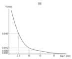
일례로, 데이터 생성 장치는, x값이 0이고 y값이 0인 제1 위치에서 제1 거리의 길이가 17 mm인 경우, 유체 유동 해석 계산을 수행하여 유체 유동 물리량 값인 유속이 0.0057 m/s라고 인식할 수 있다. 이 경우, 데이터 생성 장치는 17mm의 거리에서 제1 위치의 유체 유동 물리량 값이 0.0057m/s라는 정보를 제1 데이터 세트로 저장할 수 있다.For example, when the length of the first distance is 17 mm at the first location where the x value is 0 and the y value is 0, the data generating device performs fluid flow analysis calculation to determine that the flow velocity, which is a physical quantity value of fluid flow, is 0.0057 m/s. In this case, the data generating device may store information indicating that the value of the physical quantity of fluid flow at the first position at a distance of 17 mm is 0.0057 m/s as the first data set.
다른 일례로, 데이터 생성 장치는, x값이 0이고 y값이 0인 제1 위치에서 제1 거리의 길이가 12 mm인 경우, 유체 유동 해석 계산을 수행하여 유체 유동 물리량 값인 유속이 0.0080 m/s라고 인식할 수 있다. 이 경우, 데이터 생성 장치는 12mm의 거리에서 제1 위치의 유체 유동 물리량 값이 0.0080m/s라는 정보를 제2 데이터 세트로 저장할 수 있다.As another example, when the length of the first distance is 12 mm at the first location where the x value is 0 and the y value is 0, the data generating device performs the fluid flow analysis calculation to determine the flow velocity, which is a fluid flow physical quantity value. It can be recognized as 0.0080 m/s. In this case, the data generating device may store information indicating that the value of the physical quantity of fluid flow at the first position at a distance of 12 mm is 0.0080 m/s as a second data set.
또 다른 일례로, 데이터 생성 장치는, x 값이 0이고 y 값이 1인 제2 위치에서 제1 거리의 길이가 17 mm인 경우, 유체 유동 해석 계산을 수행하여 유체 유동 물리량 값인 유속이 0.0069 m/s라고 인식할 수 있다. 이 경우, 데이터 생성 장치는 17 mm의 거리에서 제2 위치의 유체 유동 물리량 값이 0.0069 m/s라는 정보를 제3 데이터 세트로 저장할 수 있다.As another example, when the length of the first distance is 17 mm at the second location where the x value is 0 and the y value is 1, the data generating device performs fluid flow analysis calculation to recognize that the flow velocity, which is the value of the fluid flow physical quantity, is 0.0069 m/s. In this case, the data generating device may store information indicating that the value of the physical quantity of fluid flow at the second position at a distance of 17 mm is 0.0069 m/s as a third data set.
또 다른 일례로, 데이터 생성 장치는, x 값이 0이고 y 값이 1인 제2 위치에서 제1 거리의 길이가 12 mm인 경우, 유체 유동 해석 계산을 수행하여 유체 유동 물리량 값인 유속이 0.0091 m/s라고 인식할 수 있다. 이 경우, 데이터 생성 장치는 12 mm의 거리에서 제2 위치의 유체 유동 물리량 값이 0.0091 m/s라는 정보를 제4 데이터 세트로 저장할 수 있다.As another example, when the length of the first distance is 12 mm at the second location where the x value is 0 and the y value is 1, the data generating device performs fluid flow analysis calculation to recognize that the flow velocity, which is a fluid flow physical quantity value, is 0.0091 m/s. In this case, the data generating device may store information indicating that the value of the physical quantity of fluid flow at the second position at a distance of 12 mm is 0.0091 m/s as a fourth data set.
결과적으로, 데이터 생성 장치는 도 4와 같이 웨이퍼 상의 각각의 위치 및 제1 거리의 길이 별 유체 유동 물리량 값을 구분하여 복수의 데이터 세트를 생성할 수 있다.As a result, as shown in FIG. 4 , the data generating apparatus may generate a plurality of data sets by dividing the fluid flow physical quantity value for each position on the wafer and for each length of the first distance.
샤워 헤드 제조 시스템은 단계(S310)에서 생성된 복수의 데이터 세트에 포함된 정보 간의 관계를 인식할 수 있다(S320).The shower head manufacturing system may recognize a relationship between information included in the plurality of data sets generated in step S310 (S320).
구체적으로, 샤워 헤드 제조 시스템은 조건 데이터와 유체 유동 물리량 값의 관계를 나타내는 함수에 대한 정보를 통계적 방법을 통해 계산하여 인식할 수 있다.Specifically, the shower head manufacturing system may calculate and recognize information on a function representing a relationship between condition data and a physical quantity value of a fluid flow through a statistical method.
예를 들어, 샤워 헤드 제조 시스템은 복수의 데이터 세트를 이용하여 웨이퍼의 상부 표면과 샤워 헤드 간의 제1 거리를 나타내는 제1 정보, 웨이퍼 사이의 복수의 위치를 나타내는 제2 정보 및 제1 거리의 길이에 따른 상기 복수의 위치 각각에서 측정되는 유체 유동 물리량 값에 대한 제3 정보 사이의 관계를 나타내는 함수에 대한 정보를 통계적 방법을 통해 계산할 수 있다. 이 경우, 샤워 헤드 제조 시스템은, 딥 러닝(예를 들어, 데이터 피팅(data fitting), 회귀적(regression) 뉴런 네트워크, 피드포워드(feedforward) 네트워크 등)을 통해 조건 데이터의 입력에 대응하는 최적의 관계를 나타내는 함수에 대한 정보를 추출할 수 있다. 즉, 샤워 헤드 제조 시스템은 조건 데이터가 입력되면 데이터 베이스에 저장된 최적의 관계를 나타내는 함수를 검색하여 최적의 유체 유동 물리량 값을 출력할 수 있다.For example, the shower head manufacturing system may use a plurality of data sets to calculate first information indicating a first distance between the upper surface of the wafer and the shower head, second information indicating a plurality of positions between the wafers, and information on a function indicating a relationship between third information about the physical quantity value of the fluid flow measured at each of the plurality of positions according to the length of the first distance through a statistical method. In this case, the shower head manufacturing system corresponds to the input of condition data through deep learning (eg, data fitting, regression neuron network, feedforward network, etc.). Information about a function representing an optimal relationship can be extracted. That is, when the condition data is input, the shower head manufacturing system may retrieve a function representing an optimal relationship stored in the database and output an optimal fluid flow physical quantity value.
일례로, 도 5를 참조하면, 데이터 생성 장치는 웨이퍼의 제1 위치에서 제1 거리의 길이와 유체 유동 물리 값 간의 관계를 나타내는 그래프(500)를 생성할 수 있다. 데이터 생성 장치는 상술한 통계적 방법을 사용하여 제1 거리의 길이와 유체 유동 물리 값 간의 관계를 나타내는 함수에 대한 정보를 인식할 수 있다.For example, referring to FIG. 5 , the data generating apparatus may generate a
몇몇 실시예에 따르면, 도 3의 단계(S320)에서 획득된 함수는 데이터 베이스에 저장될 수 있다.According to some embodiments, the function obtained in step S320 of FIG. 3 may be stored in a database.
한편, 데이터 베이스는 이전 시뮬레이션 결과에 대한 정보를 저장하고 있을 수 있다. 여기서, 이전 시뮬레이션 결과라 함은 이전에 통계적 방법을 통해 획득된 함수를 포함할 수 있다.Meanwhile, the database may store information on previous simulation results. Here, the previous simulation result may include a function previously obtained through a statistical method.
또한, 샤워 헤드 제조 시스템은 새로운 시뮬레이션 결과인 조건 데이터와 유체 유동 물리량 값의 상관 관계 함수를 이용하여 기존에 저장되어 있는 시뮬레이션 결과에 대한 정보를 업데이트할 수 있다.In addition, the shower head manufacturing system may update information on previously stored simulation results by using a correlation function between condition data, which is a new simulation result, and physical quantity values of fluid flow.
도 3을 다시 참조하면, 샤워 헤드 제조 시스템은 타겟 유체 유동 물리량 값을 입력 받을 수 있다(S330). 여기서, 타겟 유체 유동 물리량 값은 사용자가 원하는 유체 유동 물리량 값일 수 있다.Referring back to FIG. 3 , the shower head manufacturing system may receive a target fluid flow physical quantity value (S330). Here, the target fluid flow physical quantity value may be a fluid flow physical quantity value desired by the user.
샤워 헤드 제조 시스템은, 단계(S320)에서 인식된 관계에 기초하여 단계(S330)에서 입력 받은 타겟 유체 유동 물리량 값을 갖는 웨이퍼의 상부 표면과 샤워 헤드 간의 거리에 대한 정보를 획득할 수 있다(S340).The shower head manufacturing system may obtain information about the distance between the upper surface of the wafer having the target fluid flow physical quantity value input in step S330 and the shower head based on the relationship recognized in step S320 (S340).
도 6을 참조하면, 데이터 생성 장치는 타겟 유체 유동 물리량 값(610)(예를 들어, 0.0080 m/s)을 입력 받을 수 있다. 이 경우, 데이터 생성 장치는, 웨이퍼 상의 복수의 위치(620) 각각에서의 웨이퍼의 상부 표면과 샤워 헤드 간의 제2 거리를 나타내는 정보(630)를 복수의 데이터 세트에 포함된 정보 사이의 관계를 나타내는 함수에 대한 정보 또는 이전 시뮬레이션 결과에 대한 정보를 이용하여 획득할 수 있다.Referring to FIG. 6 , the data generating device may receive a target fluid flow physical quantity value 610 (eg, 0.0080 m/s) as an input. In this case, the data generating apparatus may obtain
예를 들어, 데이터 생성 장치는 x값이 0이고 y값이 0인 제1 위치에서 타겟 유체 유동 물리량 값인 0.0080 m/s 값을 갖는 제2 거리가 12 mm라는 정보를 획득할 수 있다. 또한, 데이터 생성 장치는 x값이 0이고 y값이 1인 제2 위치에서 타겟 유체 유동 물리량 값인 0.0080 m/s 값을 갖는 제2 거리가 14 mm라는 정보를 획득할 수 있다.For example, the data generating device may obtain information that a second distance having a target fluid flow physical quantity value of 0.0080 m/s is 12 mm at the first position where the x value is 0 and the y value is 0. In addition, the data generating device may obtain information that a second distance having a target fluid flow physical quantity value of 0.0080 m/s is 14 mm at the second position where the x value is 0 and the y value is 1.
이와 같이, 데이터 생성 장치는 복수의 위치 각각에서 타겟 유체 유동 물리량 값을 갖는 제2 거리를 나타내는 정보를 획득할 수 있다.In this way, the data generating device may obtain information indicating the second distance having the target fluid flow physical quantity value at each of a plurality of locations.
도 3을 다시 참조하면, 샤워 헤드 제조 시스템은 단계(S340)에서 획득한 웨이퍼의 상부 표면과 샤워 헤드 간의 제2 거리에 대한 제5 정보를 이용하여 샤워 헤드의 3차원 형상 데이터를 생성할 수 있다(S350).Referring back to FIG. 3 , the shower head manufacturing system may generate three-dimensional shape data of the shower head using the fifth information about the second distance between the upper surface of the wafer and the shower head obtained in step S340 (S350).
구체적으로, 데이터 생성 장치는 웨이퍼 상의 복수의 위치를 나타내는 제2 정보 및 복수의 위치 각각에서 타겟 유체 유동 물리량 값을 갖는 웨이퍼의 상부 표면과 샤워 헤드 간의 제2 거리에 대한 제5 정보를 이용하여 샤워 헤드의 하부 표면의 공간 좌표 정보를 추출할 수 있다. 데이터 생성 장치는 제2 정보에 기초하여 공간 좌표 정보 내의 x 축 및 y 축의 값을 생성할 수 있고, 제5 정보에 기초하여 공간 좌표 정보 내의 z축 값을 생성할 수 있다.Specifically, the data generating device may extract spatial coordinate information of the lower surface of the shower head by using second information indicating a plurality of locations on the wafer and fifth information about a second distance between the shower head and the upper surface of the wafer having the target fluid flow physical quantity value at each of the plurality of locations. The data generating device may generate x-axis and y-axis values in the spatial coordinate information based on the second information, and generate a z-axis value in the spatial coordinate information based on the fifth information.
도 7을 참조하면, 데이터 생성 장치는 공간 좌표 정보를 이용하여 복수의 포인트(P)를 3차원 공간으로 표현되는 이미지 데이터 상에 생성할 수 있다. 예를 들어, 이미지 데이터는 3차원 캐드와 같은 프로그램으로 생성된 데이터일 수 있다.Referring to FIG. 7 , the data generating apparatus may generate a plurality of points P on image data expressed in a 3D space using spatial coordinate information. For example, the image data may be data generated by a program such as 3D CAD.
데이터 생성 장치는 상기 추출된 공간 좌표 정보를 이용하여 샤워 헤드의 하부 표면의 형상 데이터를 생성할 수 있다. 상기 형상 데이터는 도 7에 도시된 이미지 데이터(700)일 수 있다.The data generating device may generate shape data of the lower surface of the shower head using the extracted spatial coordinate information. The shape data may be
예를 들어, 데이터 생성 장치는 복수의 포인트(P) 각각을 연결하여 하나의 3차원 면을 생성할 수 있다. 이 경우, 데이터 생성 장치는 연결 부분이 매끄럽게 되도록 격자 크기를 작게 하거나 임의의 상수를 곱한 형태로 3차원 면을 구성할 수 있다. 여기서, 3차원 면은 샤워 헤드의 하부 표면의 형상 데이터일 수 있다.For example, the data generating device may create one 3D plane by connecting each of the plurality of points P. In this case, the data generating device may configure a 3D surface in a form in which a grid size is reduced or an arbitrary constant is multiplied so that the connection portion is smooth. Here, the 3D plane may be shape data of the lower surface of the shower head.
데이터 생성 장치는 도 7에서 생성된 샤워 헤드의 하부 표면의 형상 데이터에 기 설정된 두께 수치를 반영하여 부피 형상 데이터를 생성할 수 있다. 데이터 생성 장치는 샤워 헤드의 하부 표면의 형상 데이터 및 부피 형상 데이터를 이용하여 3차원 형상 데이터를 생성할 수 있다.The data generating device may generate volume shape data by reflecting a predetermined thickness value to the shape data of the lower surface of the shower head generated in FIG. 7 . The data generating device may generate 3D shape data using shape data and volume shape data of the lower surface of the shower head.
데이터 생성 장치는 생성된 샤워 헤드의 3차원 형상 데이터에 복수의 홀을 생성할 수 있다. 여기서, 복수의 홀의 위치 및 모양은 사용자에 의해 입력된 위치 및 모양일 수도 있다.The data generating device may generate a plurality of holes in the generated 3D shape data of the shower head. Here, the positions and shapes of the plurality of holes may be the positions and shapes input by the user.
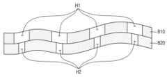
샤워 헤드의 상부 면에 포함된 샤워 홀의 직경과 샤워 헤드의 하부 면에 포함된 샤워 홀의 직경의 크기가 서로 대응하는 경우, 데이터 생성 장치는 샤워 헤드의 3차원 형상 데이터를 생성한 후 상기 생성된 3차원 형상 데이터에 복수의 샤워 홀을 생성할 수 있다.When the diameters of the shower holes included in the upper surface of the shower head and the diameters of the shower holes included in the lower surface of the shower head correspond to each other, the data generating device generates 3D shape data of the shower head and then generates a plurality of shower holes in the generated 3D shape data.
도 8을 참조하면, 샤워 헤드의 상부 면(810)에 포함된 복수의 샤워 홀(H1)의 직경은 샤워 헤드의 하부 면(820)에 포함된 복수의 샤워 홀(H2)의 직경의 크기와 상이할 수 있다. 이 경우, 데이터 생성 장치는, 상부 면(810)의 3차원 형상 데이터와 하부 면(820)의 3차원 형상 데이터를 생성한 후 각각의 3차원 형상 데이터에 샤워 홀을 생성할 수 있다.Referring to FIG. 8 , the diameters of the plurality of shower holes H1 included in the
데이터 생성 장치는 샤워 헤드의 3차원 형상 데이터를 생성한 경우, 반도체 제조 설비에 조립 시 필요한 부품 형상(예를 들어, 결속 볼트 홀, 나사선 등)을 3차원 형상 데이터에 추가로 생성할 수 있다.When the 3D shape data of the shower head is generated, the data generating device may additionally generate a part shape (eg, a binding bolt hole, a screw thread, etc.) required for assembling in a semiconductor manufacturing facility to the 3D shape data.
도 3을 다시 참조하면, 샤워 헤드 제조 시스템은 단계(S350)에서 생성된 샤워 헤드의 3차원 형상 데이터에 기초하여 3D 프린터를 이용하여 샤워 헤드를 제조할 수 있다.Referring back to FIG. 3 , the shower head manufacturing system may manufacture the shower head using a 3D printer based on the 3D shape data of the shower head generated in step S350.
샤워 헤드를 제조하는 장치는 알루미늄 합금, 크롬과 니켈을 포함하는 스테인레스강(예를 들어, SUS304) 등을 재료로 이용하여 샤워 헤드를 제조할 수 있다.An apparatus for manufacturing a shower head may manufacture a shower head using an aluminum alloy, stainless steel (eg, SUS304) containing chromium and nickel, or the like as a material.
샤워 헤드를 제조하는 장치는 3차원 형상 데이터를 이용하여 제조된 샤워 헤드에 열처리 및 표면 연마를 수행하여 샤워 헤드의 기계적, 화학적 성질을 강화시킬 수도 있다.An apparatus for manufacturing a shower head may enhance mechanical and chemical properties of the shower head by performing heat treatment and surface polishing on the manufactured shower head using 3D shape data.
몇몇 실시예에 따른 샤워 헤드 제조 시스템에 의해 생성된 샤워 헤드를 제조 설비에 장착하여 반도체 장치를 생성하는 경우, 유체 유동 특성의 비대칭성을 어느 정도 완화시킬 수 있다는 효과가 발생한다.When a semiconductor device is produced by mounting a shower head produced by the shower head manufacturing system according to some embodiments to a manufacturing facility, an effect of reducing the asymmetry of fluid flow characteristics to some extent occurs.
샤워 헤드 제조 시스템을 이용하여 제조된 샤워 헤드는 반도체 제조 설비(도 2의 200)에 장착될 수 있다. 샤워 헤드 제조 시스템을 이용하여 제조된 샤워 헤드가 장착된 반도체 제조 설비는 반도체 장치의 제조(예를 들어, 증착 공정, 식각 공정 등)에 이용될 수 있다.A shower head manufactured using the shower head manufacturing system may be installed in a semiconductor manufacturing facility ( 200 in FIG. 2 ). A semiconductor manufacturing facility equipped with a shower head manufactured using the shower head manufacturing system may be used for manufacturing a semiconductor device (eg, a deposition process, an etching process, etc.).
덧붙여, 제1 샤워 헤드 모델을 포함하는 반도체 제조 설비가 제1 반도체 장치 제조 공정에 사용되었다고 하자. 제1 반도체 장치 제조 공정이 이루어진 웨이퍼는 예를 들어, 웨이퍼의 위치에 따라 증착된 막의 두께가 불균일할 수 있다. 또는, 제1 반도체 장치 제조 공정이 이루어진 웨이퍼는 예를 들어, 웨이퍼의 위치에 따라 식각된 양이 불균일할 수 있다. 반도체 장치 제조 공정의 결과물인 웨이퍼에 불균일성이 클 경우, 반도체 장치의 수율, 성능 및 신뢰성은 저하될 수 있다.Incidentally, it is assumed that a semiconductor manufacturing facility including the first shower head model is used in a first semiconductor device manufacturing process. A wafer on which the first semiconductor device manufacturing process has been performed may have a non-uniform thickness of a deposited film depending on a position of the wafer, for example. Alternatively, the wafer on which the first semiconductor device manufacturing process has been performed may have a non-uniform etched amount depending on the location of the wafer, for example. If the non-uniformity of a wafer, which is a result of a semiconductor device manufacturing process, is large, yield, performance, and reliability of the semiconductor device may be deteriorated.
이와 같은 문제점을 개선하기 위해, 샤워 헤드 제조 시스템을 이용하여 제1 샤워 헤드 모델을 개선한 제2 샤워 헤드 모델을 제조할 수 있다. 개선된 제2 샤워 헤드 모델을 포함하는 반도체 제조 설비가 제1 반도체 장치 제조 공정에 활용됨으로써, 반도체 장치의 수율, 성능 및 신뢰성은 향상될 수 있다.In order to improve this problem, a second shower head model improved from the first shower head model may be manufactured using the shower head manufacturing system. As the semiconductor manufacturing facility including the improved second shower head model is utilized in the first semiconductor device manufacturing process, yield, performance, and reliability of the semiconductor device may be improved.
이상 첨부된 도면을 참조하여 본 발명의 실시예들을 설명하였으나, 본 발명은 상기 실시예들에 한정되는 것이 아니라 서로 다른 다양한 형태로 제조될 수 있으며, 본 발명이 속하는 기술분야에서 통상의 지식을 가진 자는 본 발명의 기술적 사상이나 필수적인 특징을 변경하지 않고서 다른 구체적인 형태로 실시될 수 있다는 것을 이해할 수 있을 것이다. 그러므로 이상에서 기술한 실시예들은 모든 면에서 예시적인 것이며 한정적이 아닌 것으로 이해해야만 한다.Although the embodiments of the present invention have been described with reference to the accompanying drawings, the present invention is not limited to the above embodiments and can be manufactured in various forms, and those skilled in the art to which the present invention belongs will understand that it can be implemented in other specific forms without changing the technical spirit or essential features of the present invention. Therefore, the embodiments described above should be understood as illustrative in all respects and not limiting.
100: 샤워 헤드 제조 시스템
110: 데이터 생성 장치
111: 제1 입력부
112: 데이터 처리부
120: 샤워 헤드 제조 장치
121: 제2 입력부
122: 제조부100: shower head manufacturing system
110: data generating device
111: first input unit
112: data processing unit
120: shower head manufacturing device
121: second input unit
122: manufacturing department
Claims (10)
Translated fromKorean상기 샤워 헤드를 포함하는 설비와 관련된 수치 정보를 포함하는 조건 데이터 및 상기 복수의 위치 각각에 대한 타겟 유체 유동 물리량 값을 입력 받는 입력부; 및
상기 함수에 대한 제4 정보 및 이전 시뮬레이션 결과에 대한 제5 정보를 저장하는 데이터 베이스를 포함하고,
상기 데이터 처리부는,
상기 제4 정보 및 상기 제5 정보 중 적어도 하나에 기초하여 상기 복수의 위치 각각에서 상기 타겟 유체 유동 물리량 값을 갖는 상기 웨이퍼의 상기 상부 표면과 상기 샤워 헤드 간의 제2 거리에 대한 제6 정보를 획득하고,
상기 제2 정보 및 상기 제6 정보를 이용하여 상기 샤워 헤드의 하부 표면의 공간 좌표 정보를 추출하고,
상기 공간 좌표 정보를 이용하여 상기 샤워 헤드의 3차원 형상 데이터를 생성하는, 샤워 헤드의 입체 형상 데이터를 생성하는 장치.A data processing unit that generates a plurality of data sets including first information indicating a plurality of first distance values between the upper surface of the wafer and the shower head, second information indicating a plurality of positions on the wafer, and third information for a physical quantity value of fluid flow, and calculates and recognizes a function representing a relationship between the first information, the second information, and the third information using the plurality of data sets through a statistical method;
an input unit for receiving condition data including numerical information related to facilities including the shower head and target fluid flow physical quantity values for each of the plurality of positions; and
A database for storing fourth information about the function and fifth information about previous simulation results;
The data processing unit,
Obtaining sixth information about a second distance between the shower head and the upper surface of the wafer having the target fluid flow physical quantity value at each of the plurality of positions based on at least one of the fourth information and the fifth information;
extracting spatial coordinate information of the lower surface of the shower head using the second information and the sixth information;
An apparatus for generating three-dimensional shape data of a shower head, wherein three-dimensional shape data of the shower head is generated using the spatial coordinate information.
상기 제3 정보는,
상기 복수의 제1 거리 값 각각의 크기에 따른 상기 복수의 위치 각각에서 측정되는 상기 유체 유동 물리량 값을 포함하는, 샤워 헤드의 입체 형상 데이터를 생성하는 장치.According to claim 1,
The third information,
Apparatus for generating three-dimensional shape data of a shower head, including the fluid flow physical quantity value measured at each of the plurality of positions according to the size of each of the plurality of first distance values.
상기 데이터 처리부는,
상기 복수의 위치 각각에서 측정되는 상기 유체 유동 물리량 값과 상기 복수의 제1 거리 값 각각의 관계를 나타내는 상기 함수를 인식하는, 샤워 헤드의 입체 형상 데이터를 생성하는 장치.According to claim 1,
The data processing unit,
Apparatus for generating three-dimensional shape data of a shower head, recognizing the function representing the relationship between the fluid flow physical quantity value measured at each of the plurality of positions and each of the plurality of first distance values.
상기 입력부는,
상기 복수의 데이터 세트를 생성하기 전에 상기 조건 데이터를 입력 받는, 샤워 헤드의 입체 형상 데이터를 생성하는 장치.According to claim 1,
The input unit,
An apparatus for generating three-dimensional shape data of a shower head, receiving the condition data before generating the plurality of data sets.
상기 데이터 처리부는,
상기 조건 데이터를 이용하여 상기 복수의 제1 거리 값 각각의 길이에 따른 상기 복수의 위치 각각에서 측정되는 상기 유체 유동 물리량 값을 상기 제3 정보로 인식하는, 샤워 헤드의 입체 형상 데이터를 생성하는 장치.According to claim 4,
The data processing unit,
Apparatus for generating three-dimensional shape data of a shower head, recognizing the fluid flow physical quantity value measured at each of the plurality of positions according to the length of each of the plurality of first distance values as the third information by using the condition data.
상기 조건 데이터는,
상기 복수의 제1 거리 값 각각과 관련된 제1 데이터, 챔버 내에 유입되는 가스에 대한 제2 데이터, 상기 샤워 헤드에 대한 제3 데이터, 상기 복수의 위치에 대한 제4 데이터 및 유동 해석 모델과 관련된 제5 데이터 중 적어도 하나를 포함하는, 샤워 헤드의 입체 형상 데이터를 생성하는 장치.According to claim 5,
The condition data,
The first data related to each of the plurality of first distance values, the second data related to the gas flowing into the chamber, the third data related to the shower head, the fourth data related to the plurality of positions, and the flow analysis model An apparatus for generating three-dimensional shape data of a shower head, including at least one of one of:
상기 데이터 처리부는,
상기 공간 좌표 정보를 이용하여 상기 하부 표면의 형상 데이터를 생성하고,
기 설정된 두께 수치를 이용하여 상기 생성된 하부 표면에 부피 형상 데이터를 생성하는, 샤워 헤드의 입체 형상 데이터를 생성하는 장치.According to claim 1,
The data processing unit,
generating shape data of the lower surface using the spatial coordinate information;
An apparatus for generating three-dimensional shape data of a shower head, generating volume shape data on the generated lower surface using a predetermined thickness value.
상기 데이터 처리부는,
상기 생성된 3차원 형상 데이터에 복수의 샤워 홀을 생성하는 것을 더 포함하는, 샤워 헤드의 입체 형상 데이터를 생성하는 장치.According to claim 1,
The data processing unit,
An apparatus for generating three-dimensional shape data of a shower head, further comprising generating a plurality of shower holes in the generated three-dimensional shape data.
상기 조건 데이터를 이용하여 웨이퍼의 상부 표면과 샤워 헤드 간의 복수의 제1 거리 값을 나타내는 제1 정보, 상기 웨이퍼 상의 복수의 위치를 나타내는 제2 정보 및 유체 유동 물리량 값에 대한 제3 정보를 포함하는 복수의 데이터 세트를 생성하고,
상기 복수의 데이터 세트를 이용하여 상기 제1 정보, 상기 제2 정보 및 상기 제3 정보 사이의 관계를 나타내는 함수를 통계적 방법을 통해 계산하여 인식하고,
상기 함수에 대한 제4 정보를 데이터 베이스에 저장하고,
상기 복수의 위치 각각에 대한 타겟 유체 유동 물리량 값을 입력 받고,
상기 데이터 베이스에 저장된 이전 시뮬레이션 결과에 대한 제5 정보를 획득하고,
상기 제4 정보 및 상기 제5 정보 중 적어도 하나에 기초하여 상기 복수의 위치 각각에서 상기 타겟 유체 유동 물리량 값을 갖는 상기 웨이퍼의 상기 상부 표면과 상기 샤워 헤드 간의 제2 거리에 대한 제6 정보를 획득하고,
상기 제2 정보 및 상기 제6 정보를 이용하여 상기 샤워 헤드의 하부 표면의 공간 좌표 정보를 추출하고,
상기 공간 좌표 정보를 이용하여 상기 하부 표면의 형상 데이터를 생성하고,
기 설정된 두께 수치를 이용하여 상기 생성된 하부 표면에 부피 형상 데이터를 생성하고,
샤워 홀의 직경 및 상기 샤워 홀의 깊이에 대한 제7 정보에 기초하여 상기 부피 형상 데이터에 복수의 샤워 홀이 생성된 입체 형상 데이터를 생성하고,
3차원 프린터를 이용하여 상기 생성된 입체 형상 데이터에 기초하여 상기 샤워 헤드를 제조하는 것을 포함하는, 샤워 헤드 제조 방법.Receive condition data including numerical information related to equipment including a shower head,
Using the condition data, a plurality of data sets including first information indicating a plurality of first distance values between the upper surface of the wafer and the shower head, second information indicating a plurality of positions on the wafer, and third information on a fluid flow physical quantity value are generated,
Calculate and recognize a function representing a relationship between the first information, the second information, and the third information using the plurality of data sets through a statistical method,
Store fourth information about the function in a database,
Receive a target fluid flow physical quantity value for each of the plurality of positions,
obtaining fifth information about previous simulation results stored in the database;
Obtaining sixth information about a second distance between the shower head and the upper surface of the wafer having the target fluid flow physical quantity value at each of the plurality of positions based on at least one of the fourth information and the fifth information;
extracting spatial coordinate information of the lower surface of the shower head using the second information and the sixth information;
generating shape data of the lower surface using the spatial coordinate information;
Creating volume shape data on the generated lower surface using a preset thickness value,
Based on the seventh information about the diameter of the shower hole and the depth of the shower hole, three-dimensional shape data in which a plurality of shower holes are generated is generated in the volume shape data,
and manufacturing the shower head based on the generated three-dimensional shape data using a 3D printer.
상기 샤워 헤드를 포함하는 설비와 관련된 수치 정보를 포함하는 조건 데이터 및 상기 복수의 위치 각각에 대한 타겟 유체 유동 물리량 값을 입력 받는 입력부;
상기 함수에 대한 제4 정보 및 이전 시뮬레이션 결과에 대한 제5 정보를 저장하는 데이터 베이스; 및
제조부를 포함하고,
상기 데이터 처리부는,
상기 제4 정보 및 상기 제5 정보 중 적어도 하나에 기초하여 상기 복수의 위치 각각에서 상기 타겟 유체 유동 물리량 값을 갖는 상기 웨이퍼의 상기 상부 표면과 상기 샤워 헤드 간의 제2 거리에 대한 제6 정보를 획득하고,
상기 제2 정보 및 상기 제6 정보를 이용하여 상기 샤워 헤드의 3차원 형상 데이터를 생성하고,
상기 제조부는,
상기 3차원 형상 데이터를 이용하여 복수의 샤워 홀을 포함하는 샤워 헤드를 생성하는, 샤워 헤드 제조 시스템.A data processing unit that generates a plurality of data sets including first information indicating a plurality of first distance values between the upper surface of the wafer and the shower head, second information indicating a plurality of positions on the wafer, and third information for a physical quantity value of fluid flow, and calculates and recognizes a function representing a relationship between the first information, the second information, and the third information using the plurality of data sets through a statistical method;
an input unit for receiving condition data including numerical information related to facilities including the shower head and target fluid flow physical quantity values for each of the plurality of positions;
a database for storing fourth information on the function and fifth information on previous simulation results; and
Including the manufacturing department,
The data processing unit,
Obtaining sixth information about a second distance between the shower head and the upper surface of the wafer having the target fluid flow physical quantity value at each of the plurality of positions based on at least one of the fourth information and the fifth information;
generating three-dimensional shape data of the shower head using the second information and the sixth information;
The manufacturing department,
A shower head manufacturing system for generating a shower head including a plurality of shower holes using the three-dimensional shape data.
Priority Applications (4)
| Application Number | Priority Date | Filing Date | Title |
|---|---|---|---|
| KR1020180008613AKR102560283B1 (en) | 2018-01-24 | 2018-01-24 | Apparatus and method for manufacturing and designing a shower head |
| US16/127,692US11182518B2 (en) | 2018-01-24 | 2018-09-11 | Apparatus and method for designing and manufacturing showerhead |
| DE102019100762.3ADE102019100762A1 (en) | 2018-01-24 | 2019-01-14 | DEVICE AND METHOD FOR DESIGNING AND PRODUCING A SPRAY HEAD |
| CN201910034623.3ACN110066988B (en) | 2018-01-24 | 2019-01-15 | Apparatus, method and system for designing and manufacturing a showerhead |
Applications Claiming Priority (1)
| Application Number | Priority Date | Filing Date | Title |
|---|---|---|---|
| KR1020180008613AKR102560283B1 (en) | 2018-01-24 | 2018-01-24 | Apparatus and method for manufacturing and designing a shower head |
Publications (2)
| Publication Number | Publication Date |
|---|---|
| KR20190090145A KR20190090145A (en) | 2019-08-01 |
| KR102560283B1true KR102560283B1 (en) | 2023-07-26 |
Family
ID=67145337
Family Applications (1)
| Application Number | Title | Priority Date | Filing Date |
|---|---|---|---|
| KR1020180008613AActiveKR102560283B1 (en) | 2018-01-24 | 2018-01-24 | Apparatus and method for manufacturing and designing a shower head |
Country Status (4)
| Country | Link |
|---|---|
| US (1) | US11182518B2 (en) |
| KR (1) | KR102560283B1 (en) |
| CN (1) | CN110066988B (en) |
| DE (1) | DE102019100762A1 (en) |
Families Citing this family (1)
| Publication number | Priority date | Publication date | Assignee | Title |
|---|---|---|---|---|
| KR102764911B1 (en)* | 2022-08-22 | 2025-02-06 | 한화정밀기계 주식회사 | Substrate processing apparatus |
Citations (1)
| Publication number | Priority date | Publication date | Assignee | Title |
|---|---|---|---|---|
| JP2017057441A (en) | 2015-09-14 | 2017-03-23 | 株式会社東芝 | Flow control device and processing device |
Family Cites Families (56)
| Publication number | Priority date | Publication date | Assignee | Title |
|---|---|---|---|---|
| JP3167562B2 (en)* | 1994-12-26 | 2001-05-21 | 日立テクノエンジニアリング株式会社 | Paste coating machine |
| JP3595853B2 (en)* | 1999-03-18 | 2004-12-02 | 日本エー・エス・エム株式会社 | Plasma CVD film forming equipment |
| US6548402B2 (en)* | 1999-06-11 | 2003-04-15 | Applied Materials, Inc. | Method of depositing a thick titanium nitride film |
| US6444039B1 (en)* | 2000-03-07 | 2002-09-03 | Simplus Systems Corporation | Three-dimensional showerhead apparatus |
| KR100400044B1 (en)* | 2001-07-16 | 2003-09-29 | 삼성전자주식회사 | Shower head of wafer treatment apparatus having gap controller |
| JP3982402B2 (en)* | 2002-02-28 | 2007-09-26 | 東京エレクトロン株式会社 | Processing apparatus and processing method |
| KR100862658B1 (en)* | 2002-11-15 | 2008-10-10 | 삼성전자주식회사 | Gas injection device of semiconductor processing system |
| KR100965758B1 (en)* | 2003-05-22 | 2010-06-24 | 주성엔지니어링(주) | Showerhead assembly of plasma enhanced chemical vapor deposition system for liquid crystal display |
| TW200508413A (en)* | 2003-08-06 | 2005-03-01 | Ulvac Inc | Device and method for manufacturing thin films |
| US6983892B2 (en)* | 2004-02-05 | 2006-01-10 | Applied Materials, Inc. | Gas distribution showerhead for semiconductor processing |
| KR100550342B1 (en)* | 2004-02-24 | 2006-02-08 | 삼성전자주식회사 | A semiconductor substrate processing apparatus comprising a gas spreading method and a shower head and a shower head |
| US20050230350A1 (en)* | 2004-02-26 | 2005-10-20 | Applied Materials, Inc. | In-situ dry clean chamber for front end of line fabrication |
| US7429410B2 (en) | 2004-09-20 | 2008-09-30 | Applied Materials, Inc. | Diffuser gravity support |
| CN101316663B (en)* | 2005-11-30 | 2012-03-14 | 武藏高科技有限公司 | Method of adjusting nozzle clearance of liquid coater and liquid coater |
| JP2007191792A (en)* | 2006-01-19 | 2007-08-02 | Atto Co Ltd | Gas separation type showerhead |
| JP2008205219A (en)* | 2007-02-20 | 2008-09-04 | Masato Toshima | Showerhead, and cvd apparatus using the same showerhead |
| US8142606B2 (en)* | 2007-06-07 | 2012-03-27 | Applied Materials, Inc. | Apparatus for depositing a uniform silicon film and methods for manufacturing the same |
| KR101004927B1 (en)* | 2008-04-24 | 2010-12-29 | 삼성엘이디 주식회사 | Shower head for CWD and chemical vapor deposition apparatus having same |
| US8053036B2 (en)* | 2008-06-02 | 2011-11-08 | Asm Japan K.K. | Method for designing shower plate for plasma CVD apparatus |
| US8702867B2 (en)* | 2008-07-08 | 2014-04-22 | Jusung Engineering Co., Ltd. | Gas distribution plate and substrate treating apparatus including the same |
| US8147648B2 (en)* | 2008-08-15 | 2012-04-03 | Lam Research Corporation | Composite showerhead electrode assembly for a plasma processing apparatus |
| WO2010041213A1 (en)* | 2008-10-08 | 2010-04-15 | Abcd Technology Sarl | Vapor phase deposition system |
| US9758869B2 (en)* | 2009-05-13 | 2017-09-12 | Applied Materials, Inc. | Anodized showerhead |
| KR20110013669A (en) | 2009-08-03 | 2011-02-10 | 주식회사 뉴엠텍 | Domed shower head |
| US20110278260A1 (en) | 2010-05-14 | 2011-11-17 | Applied Materials, Inc. | Inductive plasma source with metallic shower head using b-field concentrator |
| EP2433716A1 (en)* | 2010-09-22 | 2012-03-28 | Hexagon Technology Center GmbH | Surface spraying device with a nozzle control mechanism and a corresponding method |
| US8562785B2 (en)* | 2011-05-31 | 2013-10-22 | Lam Research Corporation | Gas distribution showerhead for inductively coupled plasma etch reactor |
| US9315899B2 (en)* | 2012-06-15 | 2016-04-19 | Novellus Systems, Inc. | Contoured showerhead for improved plasma shaping and control |
| US9121097B2 (en)* | 2012-08-31 | 2015-09-01 | Novellus Systems, Inc. | Variable showerhead flow by varying internal baffle conductance |
| US10714315B2 (en)* | 2012-10-12 | 2020-07-14 | Asm Ip Holdings B.V. | Semiconductor reaction chamber showerhead |
| US20140235069A1 (en)* | 2013-02-15 | 2014-08-21 | Novellus Systems, Inc. | Multi-plenum showerhead with temperature control |
| US9353439B2 (en)* | 2013-04-05 | 2016-05-31 | Lam Research Corporation | Cascade design showerhead for transient uniformity |
| KR101542599B1 (en)* | 2013-06-26 | 2015-08-06 | 한국생산기술연구원 | Showerhead and showerhead structure for manufacturing an electronic device having a diffusion fin |
| US9677176B2 (en)* | 2013-07-03 | 2017-06-13 | Novellus Systems, Inc. | Multi-plenum, dual-temperature showerhead |
| JP2015095551A (en)* | 2013-11-12 | 2015-05-18 | 東京エレクトロン株式会社 | Showerhead assembly and plasma processing apparatus |
| US9484190B2 (en)* | 2014-01-25 | 2016-11-01 | Yuri Glukhoy | Showerhead-cooler system of a semiconductor-processing chamber for semiconductor wafers of large area |
| KR102451499B1 (en)* | 2014-05-16 | 2022-10-06 | 어플라이드 머티어리얼스, 인코포레이티드 | Showerhead design |
| JP2016022416A (en)* | 2014-07-18 | 2016-02-08 | パナソニック株式会社 | Discharge amount adjusting method of nozzle and device therefor |
| KR102297567B1 (en)* | 2014-09-01 | 2021-09-02 | 삼성전자주식회사 | Gas injection apparatus and thin film deposition equipment including the same |
| WO2016043033A1 (en)* | 2014-09-17 | 2016-03-24 | 東京エレクトロン株式会社 | Shower head and deposition system |
| KR102363241B1 (en)* | 2015-03-27 | 2022-02-16 | 삼성전자주식회사 | Plasma-enhanced chemical vapor deposition (PE-CVD) apparatus and method of operating the same |
| JP6884711B2 (en) | 2015-05-18 | 2021-06-09 | コーニング インコーポレイテッド | Continuous processing of flexible glass ribbons to separate and stabilize the ribbons |
| US10253412B2 (en)* | 2015-05-22 | 2019-04-09 | Lam Research Corporation | Deposition apparatus including edge plenum showerhead assembly |
| US20170002465A1 (en)* | 2015-06-30 | 2017-01-05 | Lam Research Corporation | Separation of Plasma Suppression and Wafer Edge to Improve Edge Film Thickness Uniformity |
| US9899210B2 (en)* | 2015-10-20 | 2018-02-20 | Taiwan Semiconductor Manufacturing Co., Ltd. | Chemical vapor deposition apparatus and method for manufacturing semiconductor device using the same |
| CN108140551A (en) | 2015-10-26 | 2018-06-08 | 应用材料公司 | The high production rate PECVD tools handled for the chip of semiconductor manufacturing |
| JP6285411B2 (en)* | 2015-12-25 | 2018-02-28 | 株式会社日立国際電気 | Substrate processing apparatus, semiconductor device manufacturing method, and program |
| US10497542B2 (en)* | 2016-01-04 | 2019-12-03 | Daniel T. Mudd | Flow control showerhead with integrated flow restrictors for improved gas delivery to a semiconductor process |
| KR20170090194A (en)* | 2016-01-28 | 2017-08-07 | 삼성전자주식회사 | Semiconductor Manufacturing Apparatus Having a Plurality of Gas Exhausting Pipes and Gas Sensors |
| US9738977B1 (en)* | 2016-06-17 | 2017-08-22 | Lam Research Corporation | Showerhead curtain gas method and system for film profile modulation |
| KR102483547B1 (en)* | 2016-06-30 | 2023-01-02 | 삼성전자주식회사 | Gas supply unit and thin film deposition apparatus including the same |
| EP3497259A1 (en)* | 2016-08-09 | 2019-06-19 | Singulus Technologies AG | System and method for gas phase deposition |
| TWI815813B (en)* | 2017-08-04 | 2023-09-21 | 荷蘭商Asm智慧財產控股公司 | Showerhead assembly for distributing a gas within a reaction chamber |
| CN111066133B (en)* | 2017-08-11 | 2023-08-22 | 应用材料公司 | Apparatus and method for improving thermal chemical vapor deposition (CVD) uniformity |
| US10851457B2 (en)* | 2017-08-31 | 2020-12-01 | Lam Research Corporation | PECVD deposition system for deposition on selective side of the substrate |
| WO2019195601A1 (en)* | 2018-04-04 | 2019-10-10 | Lam Research Corporation | Electrostatic chuck with seal surface |
- 2018
- 2018-01-24KRKR1020180008613Apatent/KR102560283B1/enactiveActive
- 2018-09-11USUS16/127,692patent/US11182518B2/enactiveActive
- 2019
- 2019-01-14DEDE102019100762.3Apatent/DE102019100762A1/enactivePending
- 2019-01-15CNCN201910034623.3Apatent/CN110066988B/enactiveActive
Patent Citations (1)
| Publication number | Priority date | Publication date | Assignee | Title |
|---|---|---|---|---|
| JP2017057441A (en) | 2015-09-14 | 2017-03-23 | 株式会社東芝 | Flow control device and processing device |
Also Published As
| Publication number | Publication date |
|---|---|
| CN110066988A (en) | 2019-07-30 |
| DE102019100762A1 (en) | 2019-07-25 |
| CN110066988B (en) | 2022-11-25 |
| KR20190090145A (en) | 2019-08-01 |
| US11182518B2 (en) | 2021-11-23 |
| US20190228120A1 (en) | 2019-07-25 |
Similar Documents
| Publication | Publication Date | Title |
|---|---|---|
| CN107256265B (en) | A kind of search-engine results data visualization methods of exhibiting and system | |
| CN112561078A (en) | Distributed model training method, related device and computer program product | |
| US20190354656A1 (en) | Designing convective cooling channels | |
| JP6404909B2 (en) | How to calculate the output model of a technical system | |
| KR102277507B1 (en) | Systems and methods for thermo-fluid management of control spaces | |
| CN106067028A (en) | The modeling method of automatic machinery based on GPU study | |
| JP5353764B2 (en) | Automatic design support program, method and apparatus | |
| TW200928838A (en) | Use of simulation to generate predictions pertaining to a manufacturing facility | |
| KR102560283B1 (en) | Apparatus and method for manufacturing and designing a shower head | |
| US10885684B2 (en) | Estimation results display system, estimation results display method, and estimation results display program | |
| CN114346851A (en) | Blade grinding process parameter adjusting method, device, equipment and storage medium | |
| JP7478069B2 (en) | Information processing device, information processing method, and program | |
| CN113313049A (en) | Method, device, equipment, storage medium and computer program product for determining hyper-parameters | |
| Kerstein | Hierarchical parcel-swapping representation of turbulent mixing. Part 2. Application to channel flow | |
| CN117196056B (en) | Quantum evolution parameter determination method and device, electronic device and medium | |
| CN118886536A (en) | A method and device for determining target production process parameters | |
| CN115495854B (en) | Parameter calibration method, device, equipment and medium of computer aided engineering model | |
| CN107609678B (en) | A Production Scheduling Method for Homogeneous Parallel Machines Considering Moment Information Uncertainty | |
| CN115329692B (en) | Online calibration method and system for hydraulic parameters of finished oil pipeline | |
| Shu et al. | Computation of the run-length percentiles of CUSUM control charts under changes in variances | |
| Yu et al. | PIORF: Physics-Informed Ollivier-Ricci Flow for Long-Range Interactions in Mesh Graph Neural Networks | |
| CN116522781B (en) | Sample data generation method, model training method and device | |
| CN112990548A (en) | Position point determination method and device, electronic equipment and readable storage medium | |
| JP7472867B2 (en) | Method for determining heat treatment conditions for steel, method for manufacturing steel, information processing device, and program for determining heat treatment conditions for steel | |
| Xiang et al. | A chaotic time series forecasting model based on parameters simultaneous optimization algorithm |
Legal Events
| Date | Code | Title | Description |
|---|---|---|---|
| PA0109 | Patent application | Patent event code:PA01091R01D Comment text:Patent Application Patent event date:20180124 | |
| PG1501 | Laying open of application | ||
| A201 | Request for examination | ||
| PA0201 | Request for examination | Patent event code:PA02012R01D Patent event date:20201209 Comment text:Request for Examination of Application Patent event code:PA02011R01I Patent event date:20180124 Comment text:Patent Application | |
| E902 | Notification of reason for refusal | ||
| PE0902 | Notice of grounds for rejection | Comment text:Notification of reason for refusal Patent event date:20230209 Patent event code:PE09021S01D | |
| E701 | Decision to grant or registration of patent right | ||
| PE0701 | Decision of registration | Patent event code:PE07011S01D Comment text:Decision to Grant Registration Patent event date:20230720 | |
| GRNT | Written decision to grant | ||
| PR0701 | Registration of establishment | Comment text:Registration of Establishment Patent event date:20230724 Patent event code:PR07011E01D | |
| PR1002 | Payment of registration fee | Payment date:20230724 End annual number:3 Start annual number:1 | |
| PG1601 | Publication of registration |