KR102557852B1 - Tapered lead-in for interference fit fasteners - Google Patents
Tapered lead-in for interference fit fastenersDownload PDFInfo
- Publication number
- KR102557852B1 KR102557852B1KR1020170177383AKR20170177383AKR102557852B1KR 102557852 B1KR102557852 B1KR 102557852B1KR 1020170177383 AKR1020170177383 AKR 1020170177383AKR 20170177383 AKR20170177383 AKR 20170177383AKR 102557852 B1KR102557852 B1KR 102557852B1
- Authority
- KR
- South Korea
- Prior art keywords
- hole
- fastener
- shank
- section
- inlet section
- Prior art date
- Legal status (The legal status is an assumption and is not a legal conclusion. Google has not performed a legal analysis and makes no representation as to the accuracy of the status listed.)
- Active
Links
- 230000013011matingEffects0.000claimsabstractdescription79
- 230000007704transitionEffects0.000claimsabstractdescription23
- 238000000034methodMethods0.000claimsdescription27
- 239000002131composite materialSubstances0.000claimsdescription18
- 230000008878couplingEffects0.000claimsdescription7
- 238000010168coupling processMethods0.000claimsdescription7
- 238000005859coupling reactionMethods0.000claimsdescription7
- 238000003825pressingMethods0.000claimsdescription6
- 238000009434installationMethods0.000description13
- 206010016256fatigueDiseases0.000description6
- 230000000712assemblyEffects0.000description4
- 238000000429assemblyMethods0.000description4
- 239000000314lubricantSubstances0.000description4
- 239000000463materialSubstances0.000description4
- 239000011248coating agentSubstances0.000description3
- 238000000576coating methodMethods0.000description3
- 238000004519manufacturing processMethods0.000description3
- 239000007769metal materialSubstances0.000description3
- 230000036316preloadEffects0.000description3
- 229910000838Al alloyInorganic materials0.000description2
- 241001136800Anas acutaSpecies0.000description2
- 229920002430Fibre-reinforced plasticPolymers0.000description2
- 229910001069Ti alloyInorganic materials0.000description2
- 230000006835compressionEffects0.000description2
- 238000007906compressionMethods0.000description2
- 239000011151fibre-reinforced plasticSubstances0.000description2
- BXWNKGSJHAJOGX-UHFFFAOYSA-Nhexadecan-1-olChemical compoundCCCCCCCCCCCCCCCCOBXWNKGSJHAJOGX-UHFFFAOYSA-N0.000description2
- 229910001092metal group alloyInorganic materials0.000description2
- 238000012986modificationMethods0.000description2
- 230000004048modificationEffects0.000description2
- 238000007747platingMethods0.000description2
- 230000008569processEffects0.000description2
- 239000010935stainless steelSubstances0.000description2
- 229910052782aluminiumInorganic materials0.000description1
- XAGFODPZIPBFFR-UHFFFAOYSA-NaluminiumChemical compound[Al]XAGFODPZIPBFFR-UHFFFAOYSA-N0.000description1
- 239000003637basic solutionSubstances0.000description1
- 229910052793cadmiumInorganic materials0.000description1
- BDOSMKKIYDKNTQ-UHFFFAOYSA-Ncadmium atomChemical compound[Cd]BDOSMKKIYDKNTQ-UHFFFAOYSA-N0.000description1
- 229960000541cetyl alcoholDrugs0.000description1
- 125000004122cyclic groupChemical group0.000description1
- 238000010586diagramMethods0.000description1
- 230000005288electromagnetic effectEffects0.000description1
- 230000008030eliminationEffects0.000description1
- 238000003379elimination reactionMethods0.000description1
- 239000012530fluidSubstances0.000description1
- 229910001026inconelInorganic materials0.000description1
- 238000003780insertionMethods0.000description1
- 230000037431insertionEffects0.000description1
- 238000005304joiningMethods0.000description1
- 238000005259measurementMethods0.000description1
- 229910052751metalInorganic materials0.000description1
- 239000002184metalSubstances0.000description1
- QELJHCBNGDEXLD-UHFFFAOYSA-Nnickel zincChemical compound[Ni].[Zn]QELJHCBNGDEXLD-UHFFFAOYSA-N0.000description1
- 230000002093peripheral effectEffects0.000description1
- 239000000049pigmentSubstances0.000description1
- 230000000750progressive effectEffects0.000description1
- 230000001737promoting effectEffects0.000description1
- 238000000926separation methodMethods0.000description1
- 229910052709silverInorganic materials0.000description1
- 239000004332silverSubstances0.000description1
- 239000007787solidSubstances0.000description1
- 239000000243solutionSubstances0.000description1
Images


Classifications
- F—MECHANICAL ENGINEERING; LIGHTING; HEATING; WEAPONS; BLASTING
- F16—ENGINEERING ELEMENTS AND UNITS; GENERAL MEASURES FOR PRODUCING AND MAINTAINING EFFECTIVE FUNCTIONING OF MACHINES OR INSTALLATIONS; THERMAL INSULATION IN GENERAL
- F16B—DEVICES FOR FASTENING OR SECURING CONSTRUCTIONAL ELEMENTS OR MACHINE PARTS TOGETHER, e.g. NAILS, BOLTS, CIRCLIPS, CLAMPS, CLIPS OR WEDGES; JOINTS OR JOINTING
- F16B35/00—Screw-bolts; Stay-bolts; Screw-threaded studs; Screws; Set screws
- F16B35/04—Screw-bolts; Stay-bolts; Screw-threaded studs; Screws; Set screws with specially-shaped head or shaft in order to fix the bolt on or in an object
- F16B35/041—Specially-shaped shafts
- F—MECHANICAL ENGINEERING; LIGHTING; HEATING; WEAPONS; BLASTING
- F16—ENGINEERING ELEMENTS AND UNITS; GENERAL MEASURES FOR PRODUCING AND MAINTAINING EFFECTIVE FUNCTIONING OF MACHINES OR INSTALLATIONS; THERMAL INSULATION IN GENERAL
- F16B—DEVICES FOR FASTENING OR SECURING CONSTRUCTIONAL ELEMENTS OR MACHINE PARTS TOGETHER, e.g. NAILS, BOLTS, CIRCLIPS, CLAMPS, CLIPS OR WEDGES; JOINTS OR JOINTING
- F16B19/00—Bolts without screw-thread; Pins, including deformable elements; Rivets
- F16B19/04—Rivets; Spigots or the like fastened by riveting
- F16B19/05—Bolts fastening by swaged-on collars
- F—MECHANICAL ENGINEERING; LIGHTING; HEATING; WEAPONS; BLASTING
- F16—ENGINEERING ELEMENTS AND UNITS; GENERAL MEASURES FOR PRODUCING AND MAINTAINING EFFECTIVE FUNCTIONING OF MACHINES OR INSTALLATIONS; THERMAL INSULATION IN GENERAL
- F16B—DEVICES FOR FASTENING OR SECURING CONSTRUCTIONAL ELEMENTS OR MACHINE PARTS TOGETHER, e.g. NAILS, BOLTS, CIRCLIPS, CLAMPS, CLIPS OR WEDGES; JOINTS OR JOINTING
- F16B33/00—Features common to bolt and nut
- F16B33/02—Shape of thread; Special thread-forms
- F—MECHANICAL ENGINEERING; LIGHTING; HEATING; WEAPONS; BLASTING
- F16—ENGINEERING ELEMENTS AND UNITS; GENERAL MEASURES FOR PRODUCING AND MAINTAINING EFFECTIVE FUNCTIONING OF MACHINES OR INSTALLATIONS; THERMAL INSULATION IN GENERAL
- F16B—DEVICES FOR FASTENING OR SECURING CONSTRUCTIONAL ELEMENTS OR MACHINE PARTS TOGETHER, e.g. NAILS, BOLTS, CIRCLIPS, CLAMPS, CLIPS OR WEDGES; JOINTS OR JOINTING
- F16B33/00—Features common to bolt and nut
- F16B33/06—Surface treatment of parts furnished with screw-thread, e.g. for preventing seizure or fretting
- F—MECHANICAL ENGINEERING; LIGHTING; HEATING; WEAPONS; BLASTING
- F16—ENGINEERING ELEMENTS AND UNITS; GENERAL MEASURES FOR PRODUCING AND MAINTAINING EFFECTIVE FUNCTIONING OF MACHINES OR INSTALLATIONS; THERMAL INSULATION IN GENERAL
- F16B—DEVICES FOR FASTENING OR SECURING CONSTRUCTIONAL ELEMENTS OR MACHINE PARTS TOGETHER, e.g. NAILS, BOLTS, CIRCLIPS, CLAMPS, CLIPS OR WEDGES; JOINTS OR JOINTING
- F16B35/00—Screw-bolts; Stay-bolts; Screw-threaded studs; Screws; Set screws
- F16B35/04—Screw-bolts; Stay-bolts; Screw-threaded studs; Screws; Set screws with specially-shaped head or shaft in order to fix the bolt on or in an object
- F16B35/041—Specially-shaped shafts
- F16B35/044—Specially-shaped ends
- F16B35/045—Specially-shaped ends for retention or rotation by a tool
- F—MECHANICAL ENGINEERING; LIGHTING; HEATING; WEAPONS; BLASTING
- F16—ENGINEERING ELEMENTS AND UNITS; GENERAL MEASURES FOR PRODUCING AND MAINTAINING EFFECTIVE FUNCTIONING OF MACHINES OR INSTALLATIONS; THERMAL INSULATION IN GENERAL
- F16B—DEVICES FOR FASTENING OR SECURING CONSTRUCTIONAL ELEMENTS OR MACHINE PARTS TOGETHER, e.g. NAILS, BOLTS, CIRCLIPS, CLAMPS, CLIPS OR WEDGES; JOINTS OR JOINTING
- F16B37/00—Nuts or like thread-engaging members
- F—MECHANICAL ENGINEERING; LIGHTING; HEATING; WEAPONS; BLASTING
- F16—ENGINEERING ELEMENTS AND UNITS; GENERAL MEASURES FOR PRODUCING AND MAINTAINING EFFECTIVE FUNCTIONING OF MACHINES OR INSTALLATIONS; THERMAL INSULATION IN GENERAL
- F16B—DEVICES FOR FASTENING OR SECURING CONSTRUCTIONAL ELEMENTS OR MACHINE PARTS TOGETHER, e.g. NAILS, BOLTS, CIRCLIPS, CLAMPS, CLIPS OR WEDGES; JOINTS OR JOINTING
- F16B4/00—Shrinkage connections, e.g. assembled with the parts at different temperature; Force fits; Non-releasable friction-grip fastenings
- F16B4/004—Press fits, force fits, interference fits, i.e. fits without heat or chemical treatment
- F—MECHANICAL ENGINEERING; LIGHTING; HEATING; WEAPONS; BLASTING
- F16—ENGINEERING ELEMENTS AND UNITS; GENERAL MEASURES FOR PRODUCING AND MAINTAINING EFFECTIVE FUNCTIONING OF MACHINES OR INSTALLATIONS; THERMAL INSULATION IN GENERAL
- F16B—DEVICES FOR FASTENING OR SECURING CONSTRUCTIONAL ELEMENTS OR MACHINE PARTS TOGETHER, e.g. NAILS, BOLTS, CIRCLIPS, CLAMPS, CLIPS OR WEDGES; JOINTS OR JOINTING
- F16B41/00—Measures against loss of bolts, nuts, or pins; Measures against unauthorised operation of bolts, nuts or pins
- F16B41/002—Measures against loss of bolts, nuts or pins
- F—MECHANICAL ENGINEERING; LIGHTING; HEATING; WEAPONS; BLASTING
- F16—ENGINEERING ELEMENTS AND UNITS; GENERAL MEASURES FOR PRODUCING AND MAINTAINING EFFECTIVE FUNCTIONING OF MACHINES OR INSTALLATIONS; THERMAL INSULATION IN GENERAL
- F16B—DEVICES FOR FASTENING OR SECURING CONSTRUCTIONAL ELEMENTS OR MACHINE PARTS TOGETHER, e.g. NAILS, BOLTS, CIRCLIPS, CLAMPS, CLIPS OR WEDGES; JOINTS OR JOINTING
- F16B5/00—Joining sheets or plates, e.g. panels, to one another or to strips or bars parallel to them
- F16B5/01—Joining sheets or plates, e.g. panels, to one another or to strips or bars parallel to them by means of fastening elements specially adapted for honeycomb panels
- F—MECHANICAL ENGINEERING; LIGHTING; HEATING; WEAPONS; BLASTING
- F16—ENGINEERING ELEMENTS AND UNITS; GENERAL MEASURES FOR PRODUCING AND MAINTAINING EFFECTIVE FUNCTIONING OF MACHINES OR INSTALLATIONS; THERMAL INSULATION IN GENERAL
- F16B—DEVICES FOR FASTENING OR SECURING CONSTRUCTIONAL ELEMENTS OR MACHINE PARTS TOGETHER, e.g. NAILS, BOLTS, CIRCLIPS, CLAMPS, CLIPS OR WEDGES; JOINTS OR JOINTING
- F16B5/00—Joining sheets or plates, e.g. panels, to one another or to strips or bars parallel to them
- F16B5/02—Joining sheets or plates, e.g. panels, to one another or to strips or bars parallel to them by means of fastening members using screw-thread
Landscapes
- Engineering & Computer Science (AREA)
- General Engineering & Computer Science (AREA)
- Mechanical Engineering (AREA)
- Connection Of Plates (AREA)
- Insertion Pins And Rivets (AREA)
Abstract
Translated fromKoreanDescription
Translated fromKorean본 개시내용은 일반적으로, 2개 또는 그보다 많은 구조물들 또는 가공물들(이들 중 적어도 하나는 섬유 강화 플라스틱과 같은 복합 재료로 제조됨)을, 층들에서 이러한 구조물들 또는 가공물들 각각의 구멍들 내에서 패스너들의 고도의 억지 끼워맞춤(interference fit)이 달성되는 식으로 고정하기 위한 패스너들의 사용에 관한 것이다. 특히, 본 개시내용은, 볼트 또는 핀 그리고 정합(mating) 부품(예를 들어, 너트 또는 칼라)을 포함하고, 패스너를 둘러싸는 슬리브를 포함하지 않는 억지 끼워맞춤 패스너 조립체들에 관한 것이다.The present disclosure generally relates to two or more structures or workpieces, at least one of which is made of a composite material such as fiber-reinforced plastic, in layers, within holes in each of these structures or workpieces. It relates to the use of fasteners for fastening in such a way that a high degree of interference fit of the fasteners is achieved. In particular, the present disclosure relates to interference fastener assemblies that include a bolt or pin and a mating component (eg, nut or collar) and do not include a sleeve surrounding the fastener.
다수의 재료 층들을 함께 체결하기 위한 통상의 실시는 층들 위로 클램프하고, 구멍들을 뚫은 다음, 어떤 타입의 패스너를 구멍들에 삽입하고, 이로써 층들을 함께 고정하는 것이다. 패스너들은 대개 층들의 수용 구멍들에 네트(net) 또는 헐거운(clearance) 끼워맞춤으로 삽입된다. 많은 응용들에서는 이것으로 충분할 것이다. 그러나 조립된 구조물이 주기적으로 하중을 받을 때, 이들의 구멍들 내에서 패스너들의 끼워맞춤이 느슨해지는 것은 이들의 구멍들 내에서 패스너들의 빈번한 작동을 야기할 것이다. 이것은 결국 패스너, 또는 특정 구멍에 인접한 층들의 주변 영역에서의 프레팅(fretting) 및 피로 문제들로 이어질 수 있다.A common practice for fastening multiple layers of material together is to clamp over the layers, drill holes, and then insert some type of fastener into the holes, thereby securing the layers together. Fasteners are usually inserted with a net or clearance fit into the receiving apertures of the layers. For many applications this will be sufficient. However, when the assembled structure is periodically loaded, the loosening of the fit of the fasteners in their holes will cause frequent actuation of the fasteners in their holes. This in turn can lead to fretting and fatigue problems in the fastener, or in the peripheral area of the layers adjacent to a particular hole.
앞서 언급한 문제들을 해결하기 위해, 구멍 내 패스너의 고도의 억지 끼워맞춤의 이용은 조립된 구조물의 주기적 하중으로 인한 이러한 프레팅의 대부분을 효과적으로 방지할 수 있다고 알려져 있다. 높은 죔새(interference)는 움직임을 감소시키는 더 빡빡한 접합부를 생성하여, 강화된 피로 성능을 야기한다. 많은 경우들에, 대형 패스너는 층들의 수용 구멍으로 직접 밀려 들어갈 것이다. 일반적으로, 패스너가 구멍으로 밀릴 때 마모에 대한 경향을 줄이기 위해 조립 전에 패스너와 구멍에 어떤 윤활제가 가해진다. 다른 경우들에는, 슬리브가 네트 또는 헐거운 끼워맞춤으로 구멍에 미끄러진 다음에, 억지 끼워맞춤 상태를 만들기 위해 윤활제와 함께 또는 윤활제 없이 대형 패스너를 박아 넣어, 슬리브를 반경 방향으로 확장시킨다.To solve the aforementioned problems, it is known that the use of a high degree of interference fit of the fastener in the hole can effectively prevent most of these fretting due to cyclic loading of the assembled structure. High interference creates a tighter joint that reduces motion, resulting in enhanced fatigue performance. In many cases, large fasteners will be pushed directly into the receiving apertures of the layers. Generally, some lubricant is applied to the fasteners and holes prior to assembly to reduce the tendency for wear as the fasteners are pushed into the holes. In other cases, the sleeve is slid into the hole with a net or loose fit, then a large fastener is driven in with or without lubricant to create an interference fit, expanding the sleeve radially.
현재, 항공기 생산에서 복합 날개 구조물들의 조립에 사용되는 패스너들에는 두 가지 기본 솔루션들: (1) 슬리브형 볼트 시스템들; 및 (2) 캡 밀폐부(cap seal)들을 갖는 헐거운 끼워맞춤 패스너들이 있다. 슬리브형 볼트 시스템들의 사용은 다음의 단점들을 갖는다: (a) 부품들이 복잡한 설치 방법들을 필요로 하고; (b) 부품들은 손상을 방지하기 위해 취급 주의를 요하며; (c) 시스템은 (더 긴 조립 시간을 초래하는) 대규모의 공정 중 측정들을 필요로 한다. 캡 밀폐부들을 갖는 헐거운 끼워맞춤 패스너들의 사용은 다음의 단점들을 갖는다: (a) 이 시스템은 시간이 지남에 따라 증가되는 접합부 휨을 허용하여, 피로 성능에 영향을 주고; (b) 밀폐 캡 적용에 수반되는 시간의 양이 조립 시간을 증가시킨다. 또한, 금속성 항공기 구조물에 사용되는 기존의 억지 끼워맞춤 솔루션들은 패스너가 설치될 때 설치 힘 하중을 줄이도록 최적화되지 않을 수 있다. 높은 설치 힘 하중은 복합 재료를 깨지게 하거나 과도하게 박리시킬 수 있다.Currently, there are two basic solutions for fasteners used in the assembly of composite wing structures in aircraft production: (1) sleeved bolt systems; and (2) loose fit fasteners with cap seals. The use of sleeved bolt systems has the following disadvantages: (a) the parts require complex installation methods; (b) parts require careful handling to prevent damage; (c) The system requires extensive in-process measurements (resulting in longer assembly times). The use of loose fit fasteners with cap closures has the following disadvantages: (a) this system allows for increased joint warping over time, which affects fatigue performance; (b) the amount of time involved in applying the closure cap increases assembly time; Additionally, existing interference fit solutions used in metallic aircraft structures may not be optimized to reduce installation force loads when fasteners are installed. High installation force loads can fracture or excessively delaminate the composite.
설치 힘 하중들을 감소시키고 이전 단락에서 확인된 단점들 중 하나 또는 그보다 많은 단점들을 해소하는, 복합 재료에 설치하기 위한 개선된 억지 끼워맞춤 패스너들을 제공하는 것이 바람직할 것이다.It would be desirable to provide improved interference fit fasteners for installation in composite materials that reduce installation force loads and address one or more of the disadvantages identified in the previous paragraph.
아래에서 상세히 개시되는 요지는 2개 또는 그보다 많은 구조물들을 서로 부착하기 위한 억지 끼워맞춤 패스너들에 관한 것이다. 각각의 억지 끼워맞춤 패스너는 외부 돌출부들을 갖는 패스너를 포함하며, 이는 섕크(shank)와 정합부(mating portion) 사이에 테이퍼형 인입 섹션(tapered lead-in section)을 갖는다. 아래에 상세히 개시되는 실시예들에서, 테이퍼는 선형이며, 이는 테이퍼형 인입 섹션의 외부 표면이 직원뿔의 단면이 된다는 것을 의미한다. 이러한 선형적으로 점점 가늘어지는 인입 기하학적 구조는 억지 끼워맞춤 구멍들에서 설치 힘들을 감소시킴으로써, 접합부 피로 수명을 증가시키고, 유체 기밀성을 향상시키며, 전자기 효과들에 대한 민감성을 감소시킨다. 선형적으로 점점 가늘어지는 인입 기하학적 구조는 볼트가 체결될 구조물들을 뚫고 밀리면서 재료의 점진적인 압축을 촉진시킴으로써 앞서 언급한 것을 달성한다.The subject matter disclosed in detail below relates to interference fit fasteners for attaching two or more structures together. Each interference fit fastener includes a fastener with external projections, which has a tapered lead-in section between a shank and a mating portion. In the embodiments detailed below, the taper is linear, meaning that the outer surface of the tapered inlet section is the cross section of a cone. This linearly tapered inlet geometry reduces installation forces at interference holes, thereby increasing joint fatigue life, improving fluid tightness, and reducing susceptibility to electromagnetic effects. The linearly tapered entry geometry achieves the aforementioned by promoting gradual compression of the material as the bolt is pushed through the structures to be fastened.
적어도 일부 실시예들에 따르면, 억지 끼워맞춤 패스너는 섕크와, 외부 돌출부들을 갖는 정합부 사이에 배치된 전이부를 갖는 패스너를 포함하며, 전이부는 섕크/인입 교차부에서 섕크와 만나는 테이퍼형 인입 섹션 및 테이퍼형 인입 섹션과 만나는 반경형 인입 섹션을 포함한다. 테이퍼형 인입 섹션은 정합부를 향해 제1 축 방향으로 완만하게 가늘어지며, 선형인 제1 윤곽 및 20도보다 작거나 같은 테이퍼 각도를 갖고, 반경형 인입 섹션은 제1 축 방향으로 급격하게 만곡되고, 반경을 갖는 원호인 제2 윤곽을 갖는다.According to at least some embodiments, an interference fit fastener includes a fastener having a transition disposed between a shank and a mating portion having external projections, the transition comprising: a tapered lead-in section meeting the shank at a shank/lead-in intersection; and It includes a radial inlet section that meets the tapered inlet section. the tapered lead-in section gently tapering in the first axial direction toward the mating portion and having a linear first contour and a taper angle of less than or equal to 20 degrees, the radial lead-in section being sharply curved in the first axial direction; It has a second contour which is a circular arc with a radius.
본 명세서에서 사용되는 바와 같이, "외부 돌출부들"이라는 용어는 적어도 다음의 타입들: (1) 수나사(external thread)들 및 (2) 외부 환형 링들을 포괄하도록 넓게 해석되어야 한다. 예시의 목적으로, 수나사들을 갖는 패스너의 예들이 아래에서 설명된다. 그러나 본 명세서에서 개시되고 청구되는 개념들은 외부 환형 링들을 갖는 억지 끼워맞춤 패스너들에도 또한 적용된다. 따라서 아래에서 상세히 개시되는 요지는 다음의 양상들 중 하나 또는 그보다 많은 양상에 의해 특성화될 수 있다.As used herein, the term "external protrusions" should be interpreted broadly to encompass at least the following types: (1) external threads and (2) external annular rings. For purposes of illustration, examples of fasteners having external threads are described below. However, the concepts disclosed and claimed herein also apply to press-fit fasteners having outer annular rings. Accordingly, the subject matter disclosed in detail below may be characterized by one or more of the following aspects.
아래에 상세히 개시되는 요지의 일 양상은 제1 구멍을 갖는 제1 구조물과 제2 구멍을 갖는 제2 구조물을 체결하기 위한 방법이며, 제1 구멍과 제2 구멍은 동일한 직경을 갖고, 이 방법은: 제1 구멍과 제2 구멍을 정렬하여 제1 구조물과 제2 구조물을 함께 배치하는 단계; 제1 구조물의 구멍의 에지가 패스너의 정합부를 향해 완만하게 가늘어지며 20도보다 작거나 같은 테이퍼 각도를 갖는, 패스너의 테이퍼형 인입 섹션과 접촉하고 그 테이퍼형 인입 섹션을 둘러쌀 때까지 정합부를 제1 구조물의 구멍에 삽입하는 단계 ― 패스너는 헤드 및 헤드를 테이퍼형 인입 섹션에 연결하는 원통형(circular cylindrical) 섕크를 더 포함하고, 섕크는 구멍들의 직경보다 큰 직경을 가짐 ―; 섕크를 제1 구멍의 에지에 접촉시키고, 제1 구멍을 통해 밀어 넣은 다음, 패스너의 정합부가 제2 구조물을 넘어 돌출할 때까지 제2 구멍을 통해 밀어 넣도록, 정렬된 제1 구멍 및 제2 구멍으로 패스너를 더 가압하는 단계; 및 패스너의 정합부에 정합 부품을 결합하는 단계를 포함한다. 일 실시예에 따르면, 테이퍼형 인입 섹션의 외부 표면은 직원뿔의 단면이고, 테이퍼형 인입 섹션의 최대 직경은 섕크의 직경과 같고, 테이퍼형 인입 섹션의 최소 직경은 제1 구멍 및 제2 구멍의 직경보다 작다. 일 실시예에 따르면, 패스너는 테이퍼형 인입 섹션과 만나고 정합부를 향해 급격하게 만곡되며 반경을 갖는 원호인 제2 윤곽을 갖는 반경형 인입 섹션을 더 포함하고, 정합부는 반경형 인입 섹션의 최소 직경보다 작은 최대 직경을 갖는다.One aspect of the subject matter disclosed in detail below is a method for fastening a first structure having a first hole and a second structure having a second hole, the first hole and the second hole having the same diameter, the method comprising: : placing the first structure and the second structure together by aligning the first hole and the second hole; removing the mating portion until the edge of the hole in the first structure contacts and surrounds the tapered lead-in section of the fastener, the edge of which is gently tapered toward the fastener's mating portion and has a taper angle of less than or equal to 20 degrees; 1 inserting into a hole in the structure, the fastener further comprising a head and a circular cylindrical shank connecting the head to the tapered lead-in section, the shank having a diameter greater than the diameter of the holes; the first hole and the second hole aligned such that the shank is contacted to the edge of the first hole, pushed through the first hole, and then pushed through the second hole until the mating portion of the fastener protrudes beyond the second structure. further pressing the fastener into the hole; and coupling the mating component to the mating portion of the fastener. According to one embodiment, the outer surface of the tapered inlet section is a cross-section of a cone, the maximum diameter of the tapered inlet section is equal to the diameter of the shank, and the minimum diameter of the tapered inlet section is the diameter of the first hole and the second hole. smaller than According to one embodiment, the fastener further comprises a radial lead-in section having a second contour that meets the tapered lead-in section and curves sharply toward the mating portion and is an arc with a radius, the mating portion having a diameter greater than a minimum diameter of the radial lead-in section. It has a small maximum diameter.
본 명세서에서 개시되는 요지의 다른 양상은 제1 구멍을 갖는 제1 구조물과 제2 구멍을 갖는 제2 구조물을 체결하기 위한 방법이며, 제1 구멍과 제2 구멍은 동일한 구멍 직경을 갖고, 이 방법은: 제1 구멍과 제2 구멍을 정렬하여 제1 구조물과 제2 구조물을 함께 배치하는 단계; 제1 구조물의 제1 구멍의 에지가 패스너의 정합부를 향해 완만하게 가늘어지는, 패스너의 테이퍼형 인입 섹션과 접촉하고 그 테이퍼형 인입 섹션을 둘러쌀 때까지 정합부를 제1 구멍에 삽입하는 단계 ― 패스너는 헤드 및 헤드를 테이퍼형 인입 섹션에 연결하는 원통형 섕크를 더 포함하고, 섕크는 구멍 직경보다 큰 섕크 직경을 갖고, 섕크와 제1 구멍 사이의 죔새량(amount of interference)은 0.004 인치 이하임 ―; 섕크를 제1 구멍의 에지에 접촉시키고, 제1 구멍을 통해 밀어 넣은 다음, 패스너의 정합부가 제2 구조물을 넘어 돌출할 때까지 제2 구멍을 통해 밀어 넣도록, 제1 구조물 및 제2 구조물의 정렬된 구멍들로 패스너를 더 가압하는 단계; 및 패스너의 정합부에 정합 부품을 결합하는 단계를 포함한다.Another aspect of the subject matter disclosed herein is a method for fastening a first structure having a first hole and a second structure having a second hole, the first hole and the second hole having the same hole diameter, the method Silver: placing the first structure and the second structure together by aligning the first hole and the second hole; inserting the mating portion into the first hole until the edge of the first hole of the first structure contacts and surrounds the tapered lead-in section of the fastener that tapers gently toward the fastener's mating portion—the fastener; further comprises a head and a cylindrical shank connecting the head to the tapered inlet section, the shank having a shank diameter greater than the hole diameter, and an amount of interference between the shank and the first hole being 0.004 inches or less - ; of the first structure and the second structure such that the shank is brought into contact with the edge of the first hole, pushed through the first hole, and then pushed through the second hole until the mating portion of the fastener protrudes beyond the second structure. further pressing the fastener into the aligned holes; and coupling the mating component to the mating portion of the fastener.
본 명세서에서 개시되는 요지의 또 다른 양상은 패스너 및 패스너에 결합된 정합부를 포함하는 패스너 조립체이며, 패스너는: 헤드; 헤드로부터 연장하는 섕크 ― 섕크는 원통형이며 6/32 내지 16/32 인치 범위의 섕크 반경을 갖는 외부 표면을 포함함 ―; 외부 돌출부들을 포함하는 정합부; 및 섕크와 정합부 사이에 배치된 전이부를 포함하며, 전이부는 섕크/인입 교차부에서 섕크와 만나는 테이퍼형 인입 섹션 및 테이퍼형 인입 섹션과 만나는 반경형 인입 섹션을 포함한다. 제1 양상에서와 같이, 테이퍼형 인입 섹션은 정합부를 향해 제1 축 방향으로 완만하게 가늘어지며, 선형인 제1 윤곽, 0.062 내지 0.092 인치 범위의 테이퍼 길이, 및 20도보다 작거나 같은 테이퍼 각도를 갖고, 반경형 인입 섹션은 제1 축 방향으로 급격하게 만곡되고, 반경을 갖는 원호인 제2 윤곽을 갖는다.Another aspect of the subject matter disclosed herein is a fastener assembly comprising a fastener and a mating portion coupled to the fastener, the fastener comprising: a head; a shank extending from the head, the shank being cylindrical and comprising an outer surface having a shank radius ranging from 6/32 to 16/32 inches; a mating portion including external protrusions; and a transition portion disposed between the shank and the mating portion, the transition portion including a tapered lead-in section that meets the shank at the shank/lead-in intersection and a radial lead-in section that meets the tapered lead-in section. As in the first aspect, the tapered inlet section tapers gently in a first axial direction toward the mating portion and has a linear first contour, a taper length in the range of 0.062 to 0.092 inches, and a taper angle less than or equal to 20 degrees. and the radial lead-in section is sharply curved in the first axial direction and has a second contour that is a circular arc with a radius.
일부 실시예들에 따르면, 패스너는 볼트를 포함하고, 정합 부품은 볼트의 정합부의 외부 돌출부들과 서로 맞물리는 암나사(internal thread)들을 갖는 너트를 포함한다. 다른 실시예들에 따르면, 패스너는 핀을 포함하고, 정합 부품은 핀의 정합부의 외부 돌출부들과 서로 맞물리는 칼라를 포함한다.According to some embodiments, the fastener includes a bolt and the mating component includes a nut having internal threads that interdigitate with external protrusions of the mating portion of the bolt. According to other embodiments, the fastener includes a pin and the mating component includes a collar that interlocks with external projections of the mating portion of the pin.
본 명세서에서 개시되는 요지의 또 다른 양상은 조립체이며, 이 조립체는 제1 구멍을 갖는 제1 구조 엘리먼트, 제1 구조 엘리먼트의 제1 구멍과 정렬된 제2 구멍을 갖는 제2 구조 엘리먼트, 둘러싸는 슬리브 없이 제1 구조 엘리먼트 및 제2 구조 엘리먼트의 구멍들의 적어도 각각의 부분들을 점유하며, 제2 구조 엘리먼트를 넘어 연장하는 패스너, 및 제2 구조 엘리먼트에 접하며 패스너에 결합되는 정합 부품을 포함하고, 패스너는: 헤드; 헤드로부터 연장하는 섕크 ― 섕크는 원통형인 외부 표면을 포함함 ―; 외부 돌출부들을 포함하는 정합부; 및 섕크와 정합부 사이에 배치된 전이부를 포함하며, 전이부는 섕크/인입 교차부에서 섕크와 만나는 테이퍼형 인입 섹션 및 테이퍼형 인입 섹션과 만나는 반경형 인입 섹션을 포함한다. 테이퍼형 인입 섹션은 정합부를 향해 제1 축 방향으로 완만하게 가늘어지며, 선형인 제1 윤곽 및 20도보다 작거나 같은 테이퍼 각도를 갖고, 반경형 인입 섹션은 제1 축 방향으로 급격하게 만곡되고, 반경을 갖는 원호인 제2 윤곽을 갖는다. 일부 실시예들에 따르면, 제1 구조 엘리먼트와 제2 구조 엘리먼트 중 하나는 복합 재료로 제조되고, 제1 구조 엘리먼트와 제2 구조 엘리먼트 중 다른 하나는 금속성 재료로 제조된다. 다른 실시예들에 따르면, 두 구조 엘리먼트들 모두 복합 재료로 제조된다. 패스너와 제1 구조 엘리먼트 및 제2 구조 엘리먼트는 이들 사이의 슬리브 없이 접촉한다.Another aspect of the subject matter disclosed herein is an assembly comprising a first structural element having a first aperture, a second structural element having a second aperture aligned with the first aperture of the first structural element, an enclosing a fastener occupying at least portions of the apertures of the first structural element and the second structural element without a sleeve, the fastener extending beyond the second structural element, and a mating part abutting the second structural element and coupled to the fastener; a: head; a shank extending from the head, the shank comprising a cylindrical outer surface; a mating portion including external protrusions; and a transition portion disposed between the shank and the mating portion, the transition portion including a tapered lead-in section that meets the shank at the shank/lead-in intersection and a radial lead-in section that meets the tapered lead-in section. the tapered lead-in section gently tapering in the first axial direction toward the mating portion and having a linear first contour and a taper angle of less than or equal to 20 degrees, the radial lead-in section being sharply curved in the first axial direction; It has a second contour which is a circular arc with a radius. According to some embodiments, one of the first and second structural elements is made of a composite material and the other of the first and second structural elements is made of a metallic material. According to other embodiments, both structural elements are made of a composite material. The fastener and the first structural element and the second structural element are in contact without a sleeve between them.
2개 또는 그보다 많은 구조물들을 서로 부착하기 위한 개선된 억지 끼워맞춤 패스너들의 다른 양상들은 아래에서 개시된다.Other aspects of improved interference fit fasteners for attaching two or more structures together are disclosed below.
이전 섹션에서 논의된 특징들, 기능들 및 이점들은 다양한 실시예들에서는 독립적으로 달성될 수 있거나 또 다른 실시예들에서는 결합될 수 있다. 이하, 앞서 설명한 그리고 다른 양상들의 예시를 위해 도면들을 참조하여 다양한 실시예들이 설명될 것이다.
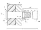
도 1은 억지 끼워맞춤 볼트의 부분 단면도를 나타내는 도면이다.
도 2는 도 1에 도시된 파선 타원(A) 내의 억지 끼워맞춤 볼트의 일부의 그림을 나타내는 도면으로, 이 그림은 일 실시예에 따른 테이퍼형 인입 섹션의 기하학적 구조를 보여준다.
도 3은 구조물의 죔새 구멍으로 밀리는 억지 끼워맞춤 볼트의 일부의 단면도를 보여주는 도면이다.
도 4는 대안적인 실시예에 따른 슬리브리스 억지 끼워맞춤 패스너 조립체에 의해 그립된 복합 및 금속성 구조물들을 포함하는 조립체의 부분 단면도를 나타내는 도면으로, 패스너 조립체는 수나사들을 갖는 핀 및 수나사들과 서로 맞물리는 내부 나사산들을 갖는 칼라를 포함한다.
도 5는 또 다른 실시예에 따른 슬리브리스 억지 끼워맞춤 패스너 조립체에 의해 그립된 복합 및 금속성 구조물들을 포함하는 조립체의 부분 단면도를 나타내는 도면으로, 패스너 조립체는 수나사들을 갖는 핀 및 수나사들과 서로 맞물리는 스웨이지 가공된(swaged) 칼라를 포함한다.
이하, 서로 다른 도면들의 비슷한 엘리먼트들이 동일한 참조 번호들을 갖는 도면들에 대해 참조가 이루어질 것이다.The features, functions and advantages discussed in the previous section may be achieved independently in various embodiments or combined in still other embodiments. DETAILED DESCRIPTION Various embodiments will now be described with reference to the drawings for illustration of the foregoing and other aspects.
1 is a view showing a partial cross-sectional view of an interference fit bolt.
FIG. 2 is a diagram showing a portion of an interference fit bolt within the dashed line ellipse A shown in FIG. 1 , which shows the geometry of a tapered entry section according to one embodiment; FIG.
Figure 3 is a view showing a cross-sectional view of a portion of the interference fit bolt pushed into the fastener hole of the structure.
4 is a partial cross-sectional view of an assembly comprising composite and metallic structures gripped by a sleeveless interference fit fastener assembly according to an alternative embodiment, the fastener assembly having a pin having external threads and an internal interlocking external threads; Includes a collar with threads.
5 is a partial cross-sectional view of an assembly comprising composite and metallic structures gripped by a sleeveless interference fit fastener assembly according to another embodiment, the fastener assembly comprising a pin having male threads and a swage interlocking with the external threads. Includes swaged collars.
Hereinafter, reference will be made to drawings in which like elements in different drawings bear the same reference numerals.
이제 억지 끼워맞춤 패스너의 다양한 실시예들이 예시를 목적으로 상세히 설명될 것이다. 아래에 개시되는 세부사항들 중 적어도 일부는 선택적인 특징들 또는 양상들에 관한 것으로, 이들은 일부 애플리케이션에서는 이에 첨부된 청구항들의 범위를 벗어나지 않고 생략될 수 있다.Various embodiments of interference fit fasteners will now be described in detail for purposes of illustration. At least some of the details disclosed below relate to optional features or aspects, which in some applications may be omitted without departing from the scope of the claims appended thereto.
특히, 2개의 구조물들을 서로 부착하기 위한 억지 끼워맞춤 패스너의 예시적인 실시예들이 아래에서 다소 상세히 설명된다. 아래에 주어진 예들에서, 구조물들 중 하나는 금속성 재료(예를 들어, 금속 합금)로 만들어지고 다른 구조물들은 합성 재료(예컨대, 섬유 강화 플라스틱)로 만들어진다. 그러나 대안적인 예들에서는, 두 구조물들 모두 복합 재료로 만들어질 수 있고 또는 두 구조물들 모두 금속성 재료로 만들어질 수 있다. 추가로, 본 명세서에서 개시되는 개념은 3개 또는 그보다 많은 구조물들을 함께 부착하는 데에도 또한 적용된다고 인식되어야 한다.In particular, exemplary embodiments of interference fit fasteners for attaching two structures together are described in some detail below. In the examples given below, one of the structures is made of a metallic material (eg metal alloy) and the other structures are made of a composite material (eg fiber reinforced plastic). However, in alternative examples, both structures may be made of a composite material or both structures may be made of a metallic material. Additionally, it should be appreciated that the concepts disclosed herein also apply to attaching three or more structures together.
도 1은 억지 끼워맞춤 볼트(2)(이하, "볼트(2)")의 부분 단면도를 나타내는 도면이다. 볼트(2)는 구조물에 카운터싱크(countersink)되도록 설계된 헤드(4) 및 헤드(4)로부터 연장하는 섕크(6)를 포함한다. 헤드(4)는 드릴 중심 딤플(dimple)(28)을 갖는다. 섕크(6)는 원통형인 외부 표면을 포함한다. 볼트(2)는 수나사들(8a)을 포함하는 나사부(8)를 더 포함하는데, 이는 섕크(6)와 나사부(8) 사이에 배치된 전이부(10)에 의해 섕크(6)에 연결된다. 나사부(8)는 정합부가 수나사들(8a)에 대해 회전되는 동안 볼트(2)를 제 위치에 유지하기 위해 설치 중에 알렌 키(Allen key)가 삽입될 수 있는 육각형 리세스(20)를 갖는다.Fig. 1 is a view showing a partial sectional view of an interference fit bolt 2 (hereinafter "
도 2는 도 1에 도시된 파선 타원(A) 내의 볼트(2)의 일부의 그림을 나타내는 도면이다. 볼트(2)의 도시된 부분은 불완전 나사산(8b)의 일부를 포함하는데, 이는 나사부(8)의 시작을 나타낸다. 이 도면은 일 실시예에 따른 전이부(10)의 기하학적 구조를 도시한다. 전이부(10)는 (도 2에서 직선 수직 파선으로 표시된) 섕크/인입 교차부(22)에서 섕크(6)와 만나는 테이퍼형 인입 섹션(14) 및 테이퍼형 인입 섹션(14)과 만나는 반경형 인입 섹션(16)을 포함한다. 전이부(10)는 반경형 인입 섹션(16)과 나사부(8) 사이의 전이 섹션(24)을 더 포함한다. 이 전이 섹션(24)은 볼트(2)의 중심 축(26)을 중심으로 회전되는 파상 곡선에 의해 형성된 외부 표면을 갖고, 테이퍼형 인입 섹션(14)의 최소 직경(D)보다 작은 직경들을 갖는다. 또한, 볼트(2)의 나사부(8)는 최소 직경(D)보다 작은 최대 직경을 갖는다.FIG. 2 is a drawing showing a portion of the
테이퍼형 인입 섹션(14)은 나사부(8)를 향해 제1 축 방향으로 완만하게 가늘어지며, 직선인 제1 윤곽을 갖는다. 반경형 인입 섹션(16)은 제1 축 방향으로 급격하게 만곡되고, 반경을 갖는 원호인 제2 윤곽을 갖는다.The tapered lead-in
혼선을 피하기 위해, 전이부(10)의 제1 윤곽 및 제2 윤곽은 다음과 같이 정의된다. 제1 윤곽은 볼트(2)의 중심 축(26)과 교차하는 평면에서의 테이퍼형 인입 섹션(14)의 외부 표면의 윤곽이다. 제2 윤곽은 중심 축(26)과 교차하는 평면에서의 반경형 인입 섹션(16)의 외부 표면이다. 일 실시예에 따르면, 중심 축(26)과 교차하는 평면에서의 섕크(6)의 윤곽은 전이부(10)의 제1 윤곽에 접한다. 테이퍼형 인입 섹션(14)의 선형적으로 점점 가늘어지는 인입 기하학적 구조는 볼트(2)가 체결될 구조물들을 뚫고 밀리면서 재료의 점진적인 압축을 촉진시킨다.To avoid confusion, the first and second contours of the
볼트(2)의 치수들은 함께 체결되는 구조물들의 두께 및 그러한 구조물들에 있는 정렬된 구멍들의 직경들에 따라 달라질 것이라고 인식되어야 한다. 다양한 예들에 따르면, 테이퍼형 인입 섹션(14)의 테이퍼 길이는 6/32 내지 16/32 인치 범위의 섕크 직경을 갖는 볼트들 또는 핀들에 대해 0.062 내지 0.092 인치 범위 이내일 수 있고, 테이퍼형 인입 섹션(14)의 테이퍼 각도는 20도 또는 그 미만일 수 있으며, 반경형 인입 섹션(16)의 반경(r)은 약 0.01 인치일 수 있다. 테이퍼형 인입 섹션(14)의 길이(L)와 섕크 직경(D) 간의 관계는 다음의 함수로 표현될 수 있다: D = -0.4578 + 10.443L.It should be appreciated that the dimensions of the
제1 구멍을 갖는 제1 구조물과 제2 구멍을 갖는 제2 구조물을 체결하기 위해 볼트(2)와 같은 수나사 패스너가 사용될 수 있으며, 제1 구멍과 제2 구멍은 동일한 직경을 갖는다. 일 실시예에 따르면, 이 방법은: 제1 구멍과 제2 구멍을 정렬하여 제1 구조물과 제2 구조물을 함께 배치하는 단계; 제1 구조물의 구멍의 에지가 테이퍼형 인입 섹션(14)과 접촉하고 그 테이퍼형 인입 섹션(14)을 둘러쌀 때까지 볼트(2)의 나사부(8)를 제1 구조물의 구멍에 삽입하는 단계; 섕크(6)를 제1 구조물의 구멍의 에지에 접촉시키고, 제1 구조물의 구멍을 통해 밀어 넣은 다음, 볼트(2)의 나사부(8)가 제2 구조물을 넘어 돌출할 때까지 제2 구조물의 구멍을 통해 밀어 넣도록, 제1 구조물 및 제2 구조물의 정렬된 구멍들로 볼트(2)를 더 가압하는 단계; 및 볼트(2)의 나사부(8)에 정합 부품을 결합하는 단계를 포함한다. 앞서 설명한 바와 같이, 테이퍼형 인입 섹션(14)은 나사부(8)를 향해 완만하게 가늘어지며, 20도보다 작거나 같은 테이퍼 각도를 갖는 한편, 섕크(6)는 원통형이며 제1 구멍 및 제2 구멍의 직경보다 더 큰 직경을 갖는다. 일 실시예에 따르면, 테이퍼형 인입 섹션(14)의 외부 표면은 직원뿔의 단면이고, 테이퍼형 인입 섹션(14)의 최대 직경은 섕크(6)의 직경과 같고, 테이퍼형 인입 섹션(14)의 최소 직경은 제1 구멍 및 제2 구멍의 직경들보다 작다.An externally threaded fastener such as
설치 중에는, 체결될 구조물의 정렬된 구멍들에 볼트(2)를 망치로 두드리기 위해 수동 리벳 건(rivet gun) 또는 자동화 시스템이 사용될 수 있다. 도 3은 구조물(18)의 죔새 구멍(19)으로 밀리는 볼트(2)의 일부를 보여준다. 볼트(2)는 구조물(18)의 구멍(19)의 직경보다 큰 직경을 갖는 원통형 섕크(6)(섕크 직경과 구멍 직경 간의 차이의 1/2은 아래에서 "죔새량"으로 지칭될 것임), 테이퍼형 인입 섹션(14), 반경형 인입 섹션(16) 및 나사부(8)(수나사들은 도 3에 도시되지 않음)를 포함한다. 테이퍼형 인입 섹션(14)의 최대 직경은 섕크(6)의 직경과 같고, 테이퍼형 인입 섹션(14)의 최소 직경은 구조물(18)의 구멍(19)의 직경보다 작다. 구멍(19)은 볼트(2)가 죔새 구멍(19) 안으로 밀릴 때 테이퍼형 인입 섹션(14)을 따라 미끄러지는 에지(21)를 갖는다. 에지(21)는 반경형일 수 있다. (바람직하게는 0.004 인치를 초과하지 않는) 죔새량 및 테이퍼 각도에 따라, 구멍(19)의 에지(21)는 볼트 삽입 중에 테이퍼 길이의 다양한 비율에 대해 테이퍼형 인입 섹션(14)을 따라 완만하게 미끄러질 것이다. 테이퍼형 인입 섹션(14)의 완만하게 가늘어지는 각도는 대략 300-500 lb만큼 힘들을 감소시킴으로써, 구조물(18)에 대한 임의의 잠재적 손상을 감소시킨다.During installation, a manual rivet gun or an automated system may be used to hammer the
볼트(2)는 나사부(8)가 마지막 구조물을 넘어 돌출할 때까지, 체결될 구조물들의 정렬된 죔새 구멍들로 밀리게 될 것이다. 그 다음, 지정된 클램핑 힘으로 (도 3에 도시되지 않은) 정합 부품이 나사부(8)에 배치된다. 어떤 경우들에는, 정합 부품은 렌치 또는 유사한 공구에 의해 맞물리도록 설계된 비-원형 렌칭(wrenching) 표면(예를 들어, 육각형) 및 암나사들을 갖는 개구를 가진 너트의 형태를 취할 수 있다. 그러나 다양한 칼라들 및 너트들이 본 명세서에 개시된 패스너들과 호환 가능하다고 인식되어야 한다. 이하, 적합한 칼라들의 두 가지 예들이 도 4 및 도 5를 참조하여 설명될 것이다.The bolt (2) will be pushed into the aligned fastener holes of the structures to be fastened until the threads (8) protrude beyond the last structure. Then, a mating component (not shown in FIG. 3 ) is placed on the threaded
도 4는 대안적인 실시예에 따른 슬리브리스 억지 끼워맞춤 패스너 조립체에 의해 그립된 복합 구조물(30) 및 금속성 구조물(32)을 포함하는 조립체의 부분 단면도를 나타내는 도면이다. 패스너 조립체는 수나사들을 갖는 억지 끼워맞춤 핀(34)(이하 "핀(34)") 및 핀(34)의 수나사들과 서로 맞물리는 암나사들을 갖는 나머지 칼라 부분(36a)을 포함한다. 도 4는 또한 나머지 칼라 부분(36a)으로부터 분리되기 전에, 나머지 칼라 부분(36a)에 연결되어 있던 칼라 렌칭 엘리먼트(36b)를 보여준다. 칼라 렌칭 엘리먼트(36b)는 렌치 또는 유사한 공구에 의해 맞물리도록 설계된 비-원형 렌치 표면(예를 들어, 육각형)을 갖는 반면, 나머지 칼라 부분(36a)은 렌칭 표면을 갖지 않음으로써, 너트의 중량에 비해 칼라의 중량을 감소시킨다. 예를 들어, 나머지 칼라 부분(36a)의 외부 윤곽은 원형일 수 있다. 나머지 칼라 부분(36a)과 칼라 렌칭 엘리먼트(36b)의 이러한 초기 결합(즉, 렌칭 동작 이전)이 도 4에서 상부 중괄호로 표시된 칼라(36)를 형성한다.4 is a partial cross-sectional view of an assembly comprising a
상세히 도시되진 않지만, 도 4에 도시된 핀(34)은 도 1에서 확인된 볼트(2)의 대응하는 구조물들과 유사한 섕크(6), 나사부(8) 및 전이부(10)를 포함한다. 보다 구체적으로, 전이부(10)는 도 2에 도시된 기하학적 구조 및 앞서 언급한 치수들을 갖는 테이퍼형 인입 섹션(14) 및 반경형 인입 섹션(16)을 포함한다. 도 4는 돌출 헤드(38)를 갖는 핀(34)을 도시하지만, 핀(34)은 대안으로 카운터싱크(즉, 플러시(flush)) 헤드를 가질 수 있다.Although not shown in detail, the
도 4에 도시된 타입의 패스너 조립체들을 설치하기 위한 프로시저는 잘 알려져 있다. 이러한 패스너 조립체는 전동 공구 또는 수공구를 사용하여 체결되는 구조물들의 한쪽으로부터 한 사람에 의해 설치될 수 있다. 이 프로시저는 교정된 토크 렌치들 및 토크 검사를 필요로 하지 않는다. 칼라(36)는 핀(34)의 나사부(8)에 나사 결합되고, 그 다음에 각각의 패스너에서 지정된 예비하중(preload)이 발생될 때까지 조여진다. 칼라 렌칭 엘리먼트(36b)는 도 4에서 확인되는 바와 같이, 설계된 예비하중에서 이탈하여, 나머지 칼라 부분(36a)을 남길 것이다. 토크-오프시 칼라 렌칭 엘리먼트(36b)의 제거는 패스너 조립체의 중량 절감을 야기한다. 패스너 조립체는 또한 구조물에 핀을 삽입하여 망치로 두드리도록 로봇 시스템을 사용하여 설치될 수 있으며, 다른 로봇 또는 사람이 구조물의 다른 쪽에서부터 칼라를 조인다.The procedure for installing fastener assemblies of the type shown in Figure 4 is well known. These fastener assemblies can be installed by one person from either side of the fastening structures using power or hand tools. This procedure does not require calibrated torque wrenches and torque checks. The
도 5는 또 다른 실시예에 따른 슬리브리스 억지 끼워맞춤 패스너 조립체에 의해 그립된 (이하 "조인트 구조물"로 지칭되는) 복합 구조물(30) 및 금속성 구조물(32)을 포함하는 조립체의 부분 단면도를 나타내는 도면이다. (흔히 체결 볼트(lockbolt)로 지칭되는) 이 패스너 조립체는 수나사들을 갖는 억지 끼워맞춤 핀(40)(이하, "핀(40)") 및 핀(40)의 수나사들과 서로 맞물리는 스웨이지 가공된 칼라(42)를 포함한다. 대안적인 실시예들에서, 핀(40)은 수나사들 대신에 외부 환형 링들을 가질 수 있다.5 shows a partial cross-sectional view of an assembly comprising a
상세히 도시되진 않지만, 도 5에 도시된 핀(40)은 도 1에서 확인된 볼트(2)의 대응하는 구조물들과 유사한 섕크(6), 나사부(8) 및 전이부(10)를 포함한다. 보다 구체적으로, 전이부(10)는 도 2에 도시된 기하학적 구조 및 앞서 언급한 치수들을 갖는 테이퍼형 인입 섹션(14) 및 반경형 인입 섹션(16)을 포함한다. 도 5는 카운터싱크(즉, 플러시) 헤드(44)를 갖는 핀(40)을 도시하지만, 핀(40)은 대안으로 돌출 헤드를 가질 수 있다.Although not shown in detail, the
도 5에 도시된 핀(40)은 조인트 구조물의 한쪽에 삽입되고, (도 5에 도시되지 않은) 스웨이지 가공되지 않은 칼라가 조인트 구조물의 다른 쪽으로부터 핀(40) 위에 배치된다. 조인트 구조물의 양측에 대한 접근이 요구된다. 체결 볼트의 설치 사이클 동안, (헐거운 맞춤의 금속 링 형태인) 스웨이지 가공되지 않은 칼라는 핀(40) 둘레에서 변형되는데, 이는 나사부(8) 상에 체결 홈들을 갖는다. 도 5에 도시되지는 않았지만, 일반적인 체결 볼트 설치 프로시저의 시작시, 핀(40)은 핀 테일(pintail)에 연결되는 것이 잘 알려져 있다. 그런 다음, 공구가 핀 테일과 맞물린다. 그 후, 핀 헤드(44)는 금속성 구조물(32)에 반대로 당겨지고 스웨이지 가공되지 않은 칼라가 복합 구조물(30)에 밀려서, 복합 구조물(30)과 금속성 구조물(32)이 서로 당겨진다. 그 다음, 공구의 원추형 공동이 칼라 아래로 가압되며, 이는 칼라의 직경을 감소시키고 칼라 재료를 더 경질인 핀(40)의 홈들로 완만하게 스웨이지 가공함으로써, 스웨이지 가공된 칼라(42)를 형성한다. 프로세스 중에 스웨이지 가공에 필요한 힘이 증가함에 따라, (도시되지 않은) 핀 테일이 분리되면 설치가 완료된다. 핀(40)과 스웨이지 가공된 칼라(42)가 결합하여 패스너 조립체를 형성한다.The
본 명세서에 개시된 볼트들 및 핀들은 바람직하게는 티타늄 합금, 알루미늄 합금, 인코넬 또는 부식 방지 강과 같은 금속 합금으로 제조된다. 본 명세서에 개시된 칼라들은 바람직하게는 티타늄 합금, 알루미늄 합금 또는 부식 방지 강으로 제조된다. 볼트들, 핀들 및 칼라들은 바람직하게는 코팅되거나 부분적으로 코팅된다. 코팅은 알루미늄 안료 코팅, 고체 필름 윤활제, 금속성 도금(카드뮴 도금, 아연-니켈 등)의 임의의 조합일 수 있다. 각각의 코팅은 세틸 알코올과 같은 추가 윤활제를 상부에 도포할 수 있다.The bolts and pins disclosed herein are preferably made of a metal alloy such as titanium alloy, aluminum alloy, inconel or corrosion resistant steel. The collars disclosed herein are preferably made of titanium alloy, aluminum alloy or corrosion resistant steel. Bolts, pins and collars are preferably coated or partially coated. The coating can be any combination of aluminum pigment coating, solid film lubricant, metallic plating (cadmium plating, zinc-nickel, etc.). Each coating may be topped with an additional lubricant such as cetyl alcohol.
본 명세서에 개시된 억지 끼워맞춤 패스너들은 항공기 생산 중에 복합 날개 구조물들의 조립에 특히 유용하다. 제안된 시스템은 기존 시스템들에 비해 다음과 같은 이익들을 갖는다.The interference fit fasteners disclosed herein are particularly useful in the assembly of composite wing structures during aircraft production. The proposed system has the following advantages compared to existing systems.
본 명세서에 개시된 억지 끼워맞춤 패스너들은 슬리브 엘리먼트를 제거함으로써, 제안된 패스너 조립체가 제조 복잡성을 감소시키고 부품 비용을 감소시킨다는 점에서 슬리브형 볼트들보다 이점들을 갖는다. 이러한 볼트들 또는 핀들을 죔새에 설치함으로써, 종래의 슬리브형 볼트 조립 프로세스에 비해 조립 시간이 크게 감소된다.The interference fit fasteners disclosed herein have advantages over sleeved bolts in that by eliminating the sleeve element, the proposed fastener assembly reduces manufacturing complexity and reduces part cost. By installing these bolts or pins into the fasteners, assembly time is greatly reduced compared to conventional sleeved bolt assembly processes.
본 명세서에 개시된 억지 끼워맞춤 패스너들은 헐거운 끼워맞춤 패스너들과 비교하여 억지 끼워맞춤 패스너들로 피로 결과들이 개선된다는 점에서, 캡 밀폐부들과 헐거운 끼워맞춤 패스너들을 설치하는 것보다 이점들을 갖는다. 이러한 패스너들은 항공기의 가장 피로 위험 영역들에 설치된다. 현재, 업계의 패스너들의 반경들은 복합 재료로의 억지 끼워맞춤을 촉진시키도록 인입부에 최적화되어 있지 않다(이는 최적이 아닌 인입 기하학적 구조로 인해 고도의 설치 힘들을 발생시킬 수 있다). 본 명세서에서 제안된 인입 기하학적 구조는 패스너들이 구멍에 "부착"되거나 설치 중에 구조물에 과도한 손상을 일으키는 것을 방지하는 데 도움이 된다. 이 시스템은 캡 밀폐부들을 추가할 필요가 없기 때문에, 조립 시간이 감소된다.The interference fit fasteners disclosed herein have advantages over installing cap closures and loose fit fasteners in that fatigue results are improved with interference fit fasteners compared to loose fit fasteners. These fasteners are installed in the most fatigue risk areas of the aircraft. Currently, the radii of fasteners in the industry are not optimized for entry to promote interference fit into composite materials (which can result in high installation forces due to sub-optimal entry geometry). The pull-in geometry proposed herein helps prevent fasteners from “sticking” to holes or causing undue damage to the structure during installation. Because this system does not require the addition of cap closures, assembly time is reduced.
추가로, 본 개시는 다음 조항들에 따른 실시예들을 포함한다:Additionally, this disclosure includes embodiments according to the following clauses:
조항 1. 제1 구멍을 갖는 제1 구조물과 제2 구멍을 갖는 제2 구조물을 체결하기 위한 방법으로서, 제1 구멍과 제2 구멍은 동일한 직경을 갖고, 이 방법은: 제1 구멍과 제2 구멍을 정렬하여 제1 구조물과 제2 구조물을 함께 배치하는 단계; 제1 구조물의 제1 구멍의 에지가 패스너의 정합부를 향해 완만하게 가늘어지며 20도보다 작거나 같은 테이퍼 각도를 갖는, 패스너의 테이퍼형 인입 섹션과 접촉하고 그 테이퍼형 인입 섹션을 둘러쌀 때까지 정합부를 제1 구멍에 삽입하는 단계 ― 패스너는 헤드 및 헤드를 테이퍼형 인입 섹션에 연결하는 원통형 섕크를 더 포함하고, 섕크는 제1 구멍 및 제2 구멍의 직경보다 큰 직경을 가짐 ―; 섕크를 제1 구멍의 에지에 접촉시키고, 제1 구멍을 통해 밀어 넣은 다음, 패스너의 정합부가 제2 구조물을 넘어 돌출할 때까지 제2 구멍을 통해 밀어 넣도록, 제1 구조물 및 제2 구조물의 정렬된 구멍들로 패스너를 더 가압하는 단계; 및 패스너의 정합부에 정합 부품을 결합하는 단계를 포함한다.
조항 2. 조항 1에 기술된 방법에서, 테이퍼형 인입 섹션의 외부 표면은 직원뿔의 단면이다.
조항 3. 조항 1 또는 조항 2에 기술된 방법에서, 테이퍼형 인입 섹션의 최대 직경은 섕크의 직경과 같고, 테이퍼형 인입 섹션의 최소 직경은 제1 구멍 및 제2 구멍의 직경보다 작다.Clause 3. In the method described in
조항 4. 조항 1 또는 조항 2에 기술된 방법에서, 패스너는 테이퍼형 인입 섹션과 만나고 정합부를 향해 급격하게 만곡되며 반경을 갖는 원호인 제2 윤곽을 갖는 반경형 인입 섹션을 더 포함한다.
조항 5. 조항 4에 기술된 방법에서, 정합부는 반경형 인입 섹션의 최소 직경보다 작은 최대 직경을 갖는다.Clause 5. In the method described in
조항 6. 상기 제1 구멍을 갖는 제1 구조물과 상기 제2 구멍을 갖는 제2 구조물을 체결하기 위한 방법으로서, 제1 구멍과 제2 구멍은 동일한 구멍 직경을 갖고, 이 방법은,
제1 구멍과 제2 구멍을 정렬하여 제1 구조물과 제2 구조물을 함께 배치하는 단계; 제1 구조물의 제1 구멍의 에지가 패스너의 정합부를 향해 완만하게 가늘어지는, 패스너의 테이퍼형 인입 섹션과 접촉하고 그 테이퍼형 인입 섹션을 둘러쌀 때까지 정합부를 제1 구멍에 삽입하는 단계 ― 패스너는 헤드 및 헤드를 테이퍼형 인입 섹션에 연결하는 원통형 섕크를 더 포함하고, 섕크는 구멍 직경보다 큰 섕크 직경을 갖고, 섕크와 제1 구멍 사이의 죔새량은 0.004 인치 이하임 ―; 섕크를 제1 구멍의 에지에 접촉시키고, 제1 구멍을 통해 밀어 넣은 다음, 패스너의 정합부가 제2 구조물을 넘어 돌출할 때까지 제2 구멍을 통해 밀어 넣도록, 제1 구조물 및 제2 구조물의 정렬된 구멍들로 패스너를 더 가압하는 단계; 및 패스너의 정합부에 정합 부품을 결합하는 단계를 포함한다.aligning the first hole and the second hole to place the first structure and the second structure together; inserting the mating portion into the first hole until the edge of the first hole of the first structure contacts and surrounds the tapered lead-in section of the fastener that tapers gently toward the fastener's mating portion—the fastener; further comprising a head and a cylindrical shank connecting the head to the tapered inlet section, the shank having a shank diameter greater than a hole diameter, and a clamping amount between the shank and the first hole being less than or equal to 0.004 inches; of the first structure and the second structure such that the shank is brought into contact with the edge of the first hole, pushed through the first hole, and then pushed through the second hole until the mating portion of the fastener protrudes beyond the second structure. further pressing the fastener into the aligned holes; and coupling the mating component to the mating portion of the fastener.
조항 7. 조항 6에 기술된 방법에서, 정합 부품은 처음에 칼라 렌칭 엘리먼트에 연결되는 칼라이고, 패스너의 정합부에 정합 부품을 결합하는 단계는, 칼라를 정합부에 나사 결합한 다음, 칼라 렌칭 엘리먼트를 이탈시키기에 충분한 예비하중이 발생될 때까지 조이는 단계를 포함한다.Clause 7. In the method described in
조항 8. 조항 6 또는 조항 7에 기술된 방법에서, 정합 부품은 칼라이고, 패스너의 정합부에 정합 부품을 결합하는 단계는 칼라를 스웨이지 가공하는 단계를 포함한다.
조항 9. 조항 6 또는 조항 7에 기술된 방법에서, 테이퍼형 인입 섹션의 외부 표면은 직원뿔의 단면이다.Clause 9. In the method described in
조항 10. 조항 6 또는 조항 7에 기술된 방법에서, 테이퍼형 인입 섹션의 최대 직경은 섕크의 직경과 같고, 테이퍼형 인입 섹션의 최소 직경은 제1 구멍 및 제2 구멍의 직경보다 작다.
조항 11. 조항 6 또는 조항 7에 기술된 방법에서, 패스너는 테이퍼형 인입 섹션과 만나고 정합부를 향해 급격하게 만곡되며 반경을 갖는 원호인 제2 윤곽을 갖는 반경형 인입 섹션을 더 포함한다.Clause 11. In the method described in
조항 12. 조항 11에 기술된 방법에서, 정합부는 반경형 인입 섹션의 최소 직경보다 작은 최대 직경을 갖는다.Clause 12. In the method described in clause 11, the mating portion has a maximum diameter smaller than the minimum diameter of the radial inlet section.
조항 13. 조립체는 제1 구멍을 갖는 제1 구조 엘리먼트, 제1 구조 엘리먼트의 제1 구멍과 정렬된 제2 구멍을 갖는 제2 구조 엘리먼트, 둘러싸는 슬리브 없이 제1 구조 엘리먼트 및 제2 구조 엘리먼트의 제1 구멍 및 제2 구멍의 적어도 각각의 부분들을 점유하며, 제2 구조 엘리먼트를 넘어 연장하는 패스너, 및 제2 구조 엘리먼트에 접하며 패스너에 결합되는 정합 부품을 포함하고, 패스너는: 헤드; 헤드로부터 연장하는 섕크 ― 섕크는 원통형인 외부 표면을 포함함 ―; 외부 돌출부들을 포함하는 정합부; 및 섕크와 정합부 사이에 배치된 전이부를 포함하며, 전이부는 섕크/인입 교차부에서 섕크와 만나는 테이퍼형 인입 섹션 및 테이퍼형 인입 섹션과 만나는 반경형 인입 섹션을 포함하고, 테이퍼형 인입 섹션은 정합부를 향해 제1 축 방향으로 완만하게 가늘어지며, 선형인 제1 윤곽 및 20도보다 작거나 같은 테이퍼 각도를 갖고, 반경형 인입 섹션은 제1 축 방향으로 급격하게 만곡되고, 반경을 갖는 원호인 제2 윤곽을 갖는다.Clause 13. The assembly comprises a first structural element having a first aperture, a second structural element having a second aperture aligned with the first aperture of the first structural element, and a combination of the first structural element and the second structural element without an enclosing sleeve. a fastener occupying at least respective portions of the first aperture and the second aperture, the fastener extending beyond the second structural element, and a mating component abutting the second structural element and coupled to the fastener, the fastener comprising: a head; a shank extending from the head, the shank comprising a cylindrical outer surface; a mating portion including external protrusions; and a transition portion disposed between the shank and the mating portion, the transition portion including a tapered lead-in section that meets the shank at a shank/inlet intersection and a radial lead-in section that meets the tapered lead-in section, wherein the tapered lead-in section comprises a mating portion. Gently tapering in the first axial direction towards the negative, having a linear first contour and a taper angle of less than or equal to 20 degrees, the radial lead-in section is sharply curved in the first axial direction and is an arc of a circle with a radius. It has 2 outlines.
조항 14. 조항 13에 기술된 조립체에서, 패스너의 섕크와 제1 구조 엘리먼트 및 제2 구조 엘리먼트는 이들 사이의 슬리브 없이 접촉한다.
조항 15. 조항 13 또는 조항 14에 기술된 조립체에서, 제1 구조 엘리먼트와 제2 구조 엘리먼트 중 하나는 복합 구조물이고, 제1 구조 엘리먼트와 제2 구조 엘리먼트 중 다른 하나는 금속성 구조물이다.Clause 15. In the assembly described in clause 13 or
조항 16. 조항 13 또는 조항 14에 기술된 조립체에서, 정합 부품은 패스너의 정합부의 외부 돌출부들과 서로 맞물리는 암나사들을 포함한다.
조항 17. 조항 13 또는 조항 14에 기술된 조립체에서, 정합 부품은 패스너의 정합부의 외부 돌출부들과 서로 맞물리는 스웨이지 가공된 칼라를 포함한다.Clause 17. In the assembly described in clause 13 or
조항 18. 조항 13 또는 조항 14에 기술된 조립체에서, 제1 윤곽은 패스너의 중심 축과 교차하는 평면에서의 테이퍼형 인입 섹션의 외부 표면의 윤곽이고, 제2 윤곽은 패스너의 중심 축과 교차하는 평면에서의 반경형 인입 섹션의 외부 표면이다.
조항 19. 조항 13 또는 조항 14에 기술된 조립체에서, 테이퍼형 인입 섹션의 최대 직경은 섕크의 직경과 같고, 테이퍼형 인입 섹션의 외부 표면은 직원뿔의 단면이다.
조항 20. 조항 13 또는 조항 14에 기술된 조립체에서, 정합부는 반경형 인입 섹션의 최소 직경보다 작은 최대 직경을 갖는다.
다양한 실시예들과 관련하여 2개의 구조물들을 서로 부착하기 위한 억지 끼워맞춤 패스너들이 설명되었지만, 이하 제시되는 청구항들의 범위를 벗어나지 않으면서 다양한 변형들이 이루어질 수 있고 등가물들이 이들의 엘리먼트들을 대신할 수도 있다고 당해 기술분야에서 통상의 지식을 가진 자들에 의해 이해될 것이다. 추가로, 청구항들의 범위를 벗어나지 않으면서 본 명세서의 교시들을 특정 상황에 맞추도록 많은 변형들이 이루어질 수도 있다.Although interference fit fasteners for attaching two structures together have been described in connection with various embodiments, it is to be understood that various modifications may be made and equivalents may be substituted for elements thereof without departing from the scope of the claims presented below. It will be understood by those skilled in the art. Additionally, many modifications may be made to adapt the teachings herein to a particular situation without departing from the scope of the claims.
청구항들에서 사용되는 바와 같이, "외부 돌출부"라는 용어는 적어도 다음의 타입들: (1) 수나사들 및 (2) 외부 환형 링들을 포괄하도록 넓게 해석되어야 한다. 청구항들에 사용되는 바와 같이, "정합 부품들"의 카테고리는 암나사 너트들과 칼라들 및 스웨이지 가공된 칼라들을 포함한다. 청구항들에서 사용되는 바와 같이, "패스너 조립체"라는 용어는: (1) 서로 결합된 볼트와 너트; (2) 서로 결합된 볼트와 칼라; (3) 서로 결합된 핀과 칼라; 및 (4) 서로 결합된 핀과 너트 중 적어도 각각에 대해 판독하도록 넓게 해석되어야 한다.As used in the claims, the term "external protrusion" should be interpreted broadly to encompass at least the following types: (1) male screws and (2) external annular rings. As used in the claims, the category of “mating parts” includes internal threaded nuts and collars and swaged collars. As used in the claims, the term “fastener assembly” means: (1) bolts and nuts coupled together; (2) bolts and collars coupled together; (3) pins and collars coupled together; and (4) a pin and a nut coupled together.
Claims (13)
Translated fromKorean상기 제1 구멍과 상기 제2 구멍은 동일한 직경을 갖고, 상기 방법은,
상기 제1 구멍과 상기 제2 구멍을 정렬하여 상기 제1 구조물과 상기 제2 구조물을 함께 배치하는 단계;
상기 제1 구조물(18)의 제1 구멍(19)의 에지(21)가, 패스너(2)의 정합부(8)를 향해 완만하게 가늘어지며 20도보다 작거나 같은 테이퍼 각도를 갖는, 상기 패스너(2)의 테이퍼형 인입 섹션(14)과 접촉하고 상기 테이퍼형 인입 섹션(14)을 둘러쌀 때까지 상기 정합부(8)를 상기 제1 구멍에 삽입하는 단계 ― 상기 패스너(2)는 헤드(4) 및 상기 헤드(4)를 상기 테이퍼형 인입 섹션(14)에 연결하는 원통형(circular cylindrical) 섕크(shank)(6)를 포함하고, 상기 섕크(6)는 매끄러운 외면을 가지고 상기 제1 구멍 및 상기 제2 구멍의 직경보다 큰 직경을 가지며, 상기 패스너(2)는 반경형 인입 섹션(16)을 더 포함하고 상기 반경형 인입 섹션(16)은 상기 테이퍼형 인입 섹션(14)과 만나고 상기 정합부(8)를 향해 만곡되며 상기 테이퍼형 인입 섹션(14)의 최소 직경과 같은 최대 직경을 가지며 반경을 갖는 원호인 제2 윤곽을 갖고, 상기 정합부(8)의 최대 직경은 상기 반경형 인입 섹션(16)의 최소 직경보다 작음 ―;
상기 섕크(6)를 상기 제1 구멍의 에지(21)에 접촉시키고, 상기 제1 구멍(19)을 통해 밀어 넣은 다음, 상기 패스너(2)의 정합부(8)가 상기 제2 구조물을 넘어 돌출할 때까지 상기 제2 구멍을 통해 밀어 넣도록, 상기 제1 구조물 및 상기 제2 구조물의 정렬된 구멍들로 상기 패스너(2)를 더 가압하는 단계; 및
상기 패스너(2)의 정합부(8)에 정합 부품(36, 42)을 결합하는 단계;를 포함하는,
체결하기 위한 방법.A method for fastening a first structure having a first hole and a second structure having a second hole, comprising:
The first hole and the second hole have the same diameter, the method comprising:
arranging the first hole and the second hole to place the first structure and the second structure together;
wherein the edge (21) of the first hole (19) of the first structure (18) tapers gently toward the mating portion (8) of the fastener (2) and has a taper angle less than or equal to 20 degrees. inserting the mating portion 8 into the first hole until it contacts and surrounds the tapered lead-in section 14 of (2) - the fastener 2 has a head (4) and a circular cylindrical shank (6) connecting the head (4) to the tapered inlet section (14), the shank (6) having a smooth outer surface and the first having a diameter greater than the diameter of the hole and the second hole, wherein the fastener (2) further comprises a radial lead-in section (16) wherein the radial lead-in section (16) meets the tapered lead-in section (14); It has a second contour that is curved toward the matching portion 8 and is a circular arc having a maximum diameter equal to the minimum diameter of the tapered inlet section 14 and having a radius, the maximum diameter of the matching portion 8 being the radius smaller than the minimum diameter of the mold inlet section 16;
The shank (6) is brought into contact with the edge (21) of the first hole, pushed through the first hole (19), and then the mating portion (8) of the fastener (2) extends over the second structure. further pressing the fastener (2) into the aligned holes of the first structure and the second structure, such that it is pushed through the second hole until it protrudes; and
coupling the mating parts (36, 42) to the mating part (8) of the fastener (2);
way to conclude.
상기 테이퍼형 인입 섹션(14)의 외부 표면은 직원뿔의 단면인,
체결하기 위한 방법.According to claim 1,
The outer surface of the tapered inlet section (14) is the cross-section of a right cone,
way to conclude.
상기 테이퍼형 인입 섹션(14)의 최대 직경은 상기 섕크(6)의 직경과 같고, 상기 테이퍼형 인입 섹션(14)의 최소 직경은 상기 제1 구멍 및 상기 제2 구멍의 직경보다 작은,
체결하기 위한 방법.According to claim 1 or 2,
The maximum diameter of the tapered inlet section (14) is equal to the diameter of the shank (6), and the minimum diameter of the tapered inlet section (14) is smaller than the diameters of the first hole and the second hole;
way to conclude.
제1 구멍을 갖는 제1 구조 엘리먼트,
상기 제1 구조 엘리먼트의 제1 구멍과 정렬된 제2 구멍을 갖는 제2 구조 엘리먼트,
둘러싸는 슬리브 없이 상기 제1 구조 엘리먼트 및 상기 제2 구조 엘리먼트의 상기 제1 구멍 및 상기 제2 구멍의 적어도 각각의 부분들을 상기 제1 구멍 및 상기 제2 구멍과 접촉한 상태로 점유하며, 상기 제2 구조 엘리먼트를 넘어 연장하는 패스너(34, 40), 및
상기 제2 구조 엘리먼트에 접하며 상기 패스너(34, 40)에 결합되는 정합 부품(36, 42)을 포함하고,
상기 패스너(34, 40)는,
헤드(38, 44);
상기 헤드(38, 44)로부터 연장하는 섕크(6) ― 상기 섕크(6)는 원통형인 매끄러운 외부 표면을 포함함 ―;
외부 돌출부들을 포함하는 정합부(8); 및
상기 섕크(6)와 상기 정합부(8) 사이에 배치된 전이부(10)를 포함하며,
상기 전이부(10)는 섕크/인입 교차부(22)에서 상기 섕크(6)와 만나는 테이퍼형 인입 섹션(14) 및 상기 테이퍼형 인입 섹션(14)과 만나는 반경형 인입 섹션(16)을 포함하고,
상기 테이퍼형 인입 섹션(14)은 상기 정합부(8)를 향해 제1 축 방향으로 완만하게 가늘어지며, 선형인 제1 윤곽 및 20도보다 작거나 같은 테이퍼 각도를 갖고,
상기 반경형 인입 섹션(16)은 상기 제1 축 방향으로 만곡되고, 상기 테이퍼형 인입 섹션(14)의 최소 직경과 같은 최대 직경을 가지며 반경을 갖는 원호인 제2 윤곽을 갖고,
상기 정합부(8)의 최대 직경은 상기 반경형 인입 섹션(16)의 최소 직경보다 작은,
조립체.As an assembly,
a first structural element having a first aperture;
a second structural element having a second aperture aligned with the first aperture of the first structural element;
occupying at least respective portions of the first hole and the second hole of the first structural element and the second structural element without an enclosing sleeve in contact with the first hole and the second hole; 2 fasteners (34, 40) extending beyond the structural elements, and
a mating component (36, 42) abutting the second structural element and coupled to the fastener (34, 40);
The fasteners 34 and 40,
heads 38 and 44;
a shank 6 extending from the head 38, 44, the shank 6 comprising a cylindrical smooth outer surface;
a mating portion 8 comprising external protrusions; and
It includes a transition part 10 disposed between the shank 6 and the matching part 8,
The transition portion (10) includes a tapered inlet section (14) that meets the shank (6) at a shank/inlet intersection (22) and a radial inlet section (16) that meets the tapered inlet section (14). do,
the tapered inlet section (14) tapers gently in a first axial direction toward the mating portion (8), has a linear first contour and a taper angle less than or equal to 20 degrees;
the radial inlet section 16 is curved in the first axial direction, has a maximum diameter equal to the minimum diameter of the tapered inlet section 14, and has a second contour that is a circular arc with a radius;
The maximum diameter of the matching portion (8) is smaller than the minimum diameter of the radial inlet section (16).
assembly.
상기 패스너(34, 40)의 섕크(6)와 상기 제1 구조 엘리먼트 및 상기 제2 구조 엘리먼트는 서로 접촉하는,
조립체.According to claim 4,
the shank (6) of the fastener (34, 40) and the first structural element and the second structural element are in contact with each other;
assembly.
상기 제1 구조 엘리먼트와 상기 제2 구조 엘리먼트 중 하나는 복합 구조물(30)이고, 상기 제1 구조 엘리먼트와 상기 제2 구조 엘리먼트 중 다른 하나는 금속성 구조물(32)인,
조립체.According to claim 4 or 5,
wherein one of the first structural element and the second structural element is a composite structure (30) and the other of the first structural element and the second structural element is a metallic structure (32).
assembly.
상기 정합 부품(36, 42)은 상기 패스너(34, 40)의 정합부(8)의 외부 돌출부들과 서로 맞물리는 암나사(internal thread)들을 포함하는,
조립체.According to claim 4 or 5,
wherein the mating parts (36, 42) include internal threads that engage with the external projections of the mating portion (8) of the fastener (34, 40).
assembly.
상기 정합 부품(36, 42)은 상기 패스너(34, 40)의 정합부(8)의 외부 돌출부들과 서로 맞물리는 스웨이지 가공된 칼라(42)를 포함하는,
조립체.According to claim 4 or 5,
wherein the mating component (36, 42) includes a swaged collar (42) that engages with the outer projections of the mating portion (8) of the fastener (34, 40).
assembly.
상기 제1 윤곽은 상기 패스너(34, 40)의 중심 축(26)과 교차하는 평면에서의 상기 테이퍼형 인입 섹션(14)의 외부 표면의 윤곽이고,
상기 제2 윤곽은 상기 패스너(34, 40)의 중심 축(26)과 교차하는 평면에서의 상기 반경형 인입 섹션(16)의 외부 표면인,
조립체.According to claim 4 or 5,
the first contour is the contour of the outer surface of the tapered lead-in section (14) in a plane intersecting the central axis (26) of the fastener (34, 40);
wherein the second contour is the outer surface of the radial lead-in section (16) in a plane intersecting the central axis (26) of the fastener (34, 40).
assembly.
상기 테이퍼형 인입 섹션(14)의 최대 직경은 상기 섕크(6)의 직경과 같고, 상기 테이퍼형 인입 섹션(14)의 외부 표면은 직원뿔의 단면인,
조립체.According to claim 4 or 5,
The maximum diameter of the tapered inlet section (14) is equal to the diameter of the shank (6), and the outer surface of the tapered inlet section (14) is a cross-section of a cone.
assembly.
Applications Claiming Priority (2)
| Application Number | Priority Date | Filing Date | Title |
|---|---|---|---|
| US15/437,234 | 2017-02-20 | ||
| US15/437,234US10711814B2 (en) | 2017-02-20 | 2017-02-20 | Tapered lead-in for interference fit fasteners |
Publications (2)
| Publication Number | Publication Date |
|---|---|
| KR20180096487A KR20180096487A (en) | 2018-08-29 |
| KR102557852B1true KR102557852B1 (en) | 2023-07-19 |
Family
ID=60654645
Family Applications (1)
| Application Number | Title | Priority Date | Filing Date |
|---|---|---|---|
| KR1020170177383AActiveKR102557852B1 (en) | 2017-02-20 | 2017-12-21 | Tapered lead-in for interference fit fasteners |
Country Status (6)
| Country | Link |
|---|---|
| US (2) | US10711814B2 (en) |
| EP (1) | EP3364050B1 (en) |
| JP (1) | JP7145604B2 (en) |
| KR (1) | KR102557852B1 (en) |
| CN (1) | CN108457960B (en) |
| CA (2) | CA3179088A1 (en) |
Families Citing this family (14)
| Publication number | Priority date | Publication date | Assignee | Title |
|---|---|---|---|---|
| WO2018026332A1 (en)* | 2016-08-01 | 2018-02-08 | Coskun Kenan | A connection system |
| US10711814B2 (en)* | 2017-02-20 | 2020-07-14 | The Boeing Company | Tapered lead-in for interference fit fasteners |
| WO2019226144A1 (en)* | 2018-05-21 | 2019-11-28 | Arconic Inc. | Fastener including a transition zone and method of use thereof |
| US11225989B2 (en)* | 2018-09-20 | 2022-01-18 | The Boeing Company | Indexing pins and indexing clamps for aligning a first body and a second body of a structure |
| US10711815B2 (en) | 2018-09-20 | 2020-07-14 | The Boeing Company | Indexing pins, indexing clamps, and methods of aligning a first body and a second body of a structure |
| US10690160B2 (en) | 2018-09-20 | 2020-06-23 | The Boeing Company | Methods of aligning a first body and a second body of a structure |
| CA3126599A1 (en)* | 2019-02-07 | 2020-08-13 | Howmet Aerospace Inc. | Blind fastener and method of installation thereof |
| US20200291979A1 (en)* | 2019-03-15 | 2020-09-17 | Roller Bearing Company Of America, Inc. | Bolt interface coating and thread transition geometry for sleeved fasteners used in composite applications |
| CN110566566B (en)* | 2019-09-17 | 2022-01-04 | 青岛交建集团有限公司 | Novel protection device based on road and bridge protection |
| EP3839168A1 (en)* | 2019-12-19 | 2021-06-23 | Hilti Aktiengesellschaft | Fastener and façade |
| WO2021239220A1 (en)* | 2020-05-27 | 2021-12-02 | Volvo Truck Corporation | A fastening element and a vehicle arrangement |
| CN114876968B (en)* | 2022-07-12 | 2022-10-11 | 四川工程职业技术学院 | Connecting structure of positioning cone |
| DE102022121435A1 (en)* | 2022-08-24 | 2024-02-29 | Ejot Se & Co. Kg | Screw for direct screwing into a component |
| US12247609B2 (en) | 2023-07-19 | 2025-03-11 | The Boeing Company | Fastener systems and methods for joining multiple substrates of workpiece |
Citations (3)
| Publication number | Priority date | Publication date | Assignee | Title |
|---|---|---|---|---|
| JP2004504944A (en)* | 1998-10-29 | 2004-02-19 | ハック インターナショナル,インコーポレイテッド | Lightweight screw fasteners and thread rolling dies |
| JP2008075876A (en)* | 2006-09-21 | 2008-04-03 | Alcoa Global Fasteners Inc | Interference fastener with high performance sleeve for composite applications |
| JP2008518164A (en)* | 2004-10-22 | 2008-05-29 | ボルボ ラストバグナー アーベー | Fastening body |
Family Cites Families (10)
| Publication number | Priority date | Publication date | Assignee | Title |
|---|---|---|---|---|
| US5018920A (en) | 1989-01-23 | 1991-05-28 | Mcdonnell Douglas Corporation | Interference fit bolt and sleeve |
| WO2009052325A1 (en) | 2007-10-16 | 2009-04-23 | Fatigue Technology, Inc. | Expandable fastener assembly with deformed collar |
| US9289815B2 (en)* | 2011-12-29 | 2016-03-22 | Standard Lifters, Inc. | Modular pilot assembly with self-contained stripper and method for metal forming dies |
| FR3008754B1 (en) | 2013-07-19 | 2015-09-04 | Lisi Aerospace | METAL FASTENING |
| FR3013781A1 (en)* | 2013-11-25 | 2015-05-29 | Airbus Operations Sas | FIXING ELEMENT FOR PARTS OF AN ASSEMBLY |
| US9908637B2 (en)* | 2014-05-23 | 2018-03-06 | The Boeing Company | Modified shank fasteners for electromagnetic effect (EME) technology |
| FR3026446B1 (en)* | 2014-09-30 | 2017-12-01 | Lisi Aerospace | LUBRICATED INTERFERENCE FASTENING |
| CN204312500U (en)* | 2014-11-24 | 2015-05-06 | 玉环精工机械制造有限公司 | A kind of connecting-rod bolts |
| US10641307B2 (en)* | 2017-02-20 | 2020-05-05 | The Boeing Company | Radiused lead-in for interference fit fasteners |
| US10711814B2 (en)* | 2017-02-20 | 2020-07-14 | The Boeing Company | Tapered lead-in for interference fit fasteners |
- 2017
- 2017-02-20USUS15/437,234patent/US10711814B2/enactiveActive
- 2017-11-21JPJP2017223418Apatent/JP7145604B2/enactiveActive
- 2017-11-29EPEP17204423.2Apatent/EP3364050B1/enactiveActive
- 2017-12-11CACA3179088Apatent/CA3179088A1/enactivePending
- 2017-12-11CACA2988522Apatent/CA2988522C/enactiveActive
- 2017-12-15CNCN201711345501.3Apatent/CN108457960B/enactiveActive
- 2017-12-21KRKR1020170177383Apatent/KR102557852B1/enactiveActive
- 2020
- 2020-06-16USUS16/902,378patent/US11168721B2/enactiveActive
Patent Citations (3)
| Publication number | Priority date | Publication date | Assignee | Title |
|---|---|---|---|---|
| JP2004504944A (en)* | 1998-10-29 | 2004-02-19 | ハック インターナショナル,インコーポレイテッド | Lightweight screw fasteners and thread rolling dies |
| JP2008518164A (en)* | 2004-10-22 | 2008-05-29 | ボルボ ラストバグナー アーベー | Fastening body |
| JP2008075876A (en)* | 2006-09-21 | 2008-04-03 | Alcoa Global Fasteners Inc | Interference fastener with high performance sleeve for composite applications |
Also Published As
| Publication number | Publication date |
|---|---|
| US10711814B2 (en) | 2020-07-14 |
| CA3179088A1 (en) | 2018-08-20 |
| JP7145604B2 (en) | 2022-10-03 |
| CN108457960A (en) | 2018-08-28 |
| EP3364050A1 (en) | 2018-08-22 |
| JP2018136022A (en) | 2018-08-30 |
| CA2988522C (en) | 2023-02-28 |
| CN108457960B (en) | 2021-07-30 |
| US20200309173A1 (en) | 2020-10-01 |
| EP3364050B1 (en) | 2021-02-24 |
| US11168721B2 (en) | 2021-11-09 |
| CA2988522A1 (en) | 2018-08-20 |
| US20180238361A1 (en) | 2018-08-23 |
| KR20180096487A (en) | 2018-08-29 |
Similar Documents
| Publication | Publication Date | Title |
|---|---|---|
| KR102557852B1 (en) | Tapered lead-in for interference fit fasteners | |
| KR102549440B1 (en) | Radiused lead-in for interference fit fasteners | |
| US20190162222A1 (en) | Blind fastener with frangible nut | |
| US8348566B2 (en) | Blind fastener | |
| US10267347B2 (en) | Blind fastener | |
| US3290982A (en) | Lockbolt construction including swaged nut | |
| US7033120B2 (en) | Blind fastener and drive nut assembly and method of installation thereof | |
| US11585364B2 (en) | Blind fastener | |
| US20230112581A1 (en) | Multi-piece fastener comprising a tapered threaded portion and method of fastening | |
| US20190032695A1 (en) | Internal positive stop, break-off flushness in blind fasteners | |
| US20240318679A1 (en) | Fastener, fastening assembly and method of installing a fastener | |
| CA1043547A (en) | Method of preloading and crimping fasteners |
Legal Events
| Date | Code | Title | Description |
|---|---|---|---|
| PA0109 | Patent application | Patent event code:PA01091R01D Comment text:Patent Application Patent event date:20171221 | |
| PG1501 | Laying open of application | ||
| A201 | Request for examination | ||
| PA0201 | Request for examination | Patent event code:PA02012R01D Patent event date:20201217 Comment text:Request for Examination of Application Patent event code:PA02011R01I Patent event date:20171221 Comment text:Patent Application | |
| E902 | Notification of reason for refusal | ||
| PE0902 | Notice of grounds for rejection | Comment text:Notification of reason for refusal Patent event date:20221207 Patent event code:PE09021S01D | |
| E701 | Decision to grant or registration of patent right | ||
| PE0701 | Decision of registration | Patent event code:PE07011S01D Comment text:Decision to Grant Registration Patent event date:20230620 | |
| GRNT | Written decision to grant | ||
| PR0701 | Registration of establishment | Comment text:Registration of Establishment Patent event date:20230717 Patent event code:PR07011E01D | |
| PR1002 | Payment of registration fee | Payment date:20230717 End annual number:3 Start annual number:1 | |
| PG1601 | Publication of registration |