KR102556390B1 - Automatic Invasion Device to Human Body and Method for Controlling the Same Device - Google Patents
Automatic Invasion Device to Human Body and Method for Controlling the Same DeviceDownload PDFInfo
- Publication number
- KR102556390B1 KR102556390B1KR1020200123787AKR20200123787AKR102556390B1KR 102556390 B1KR102556390 B1KR 102556390B1KR 1020200123787 AKR1020200123787 AKR 1020200123787AKR 20200123787 AKR20200123787 AKR 20200123787AKR 102556390 B1KR102556390 B1KR 102556390B1
- Authority
- KR
- South Korea
- Prior art keywords
- unit
- needle
- target
- slope
- invasion
- Prior art date
- Legal status (The legal status is an assumption and is not a legal conclusion. Google has not performed a legal analysis and makes no representation as to the accuracy of the status listed.)
- Active
Links
- 230000009545invasionEffects0.000titleclaimsabstractdescription45
- 238000000034methodMethods0.000titleclaimsdescription57
- 239000000523sampleSubstances0.000claimsdescription51
- 238000003825pressingMethods0.000claimsdescription26
- 238000002347injectionMethods0.000claimsdescription21
- 239000007924injectionSubstances0.000claimsdescription21
- 238000012546transferMethods0.000claimsdescription20
- 238000001514detection methodMethods0.000claimsdescription14
- 210000003462veinAnatomy0.000description20
- 238000002604ultrasonographyMethods0.000description19
- 230000008569processEffects0.000description16
- 210000004204blood vesselAnatomy0.000description14
- 230000006835compressionEffects0.000description14
- 238000007906compressionMethods0.000description14
- 238000006243chemical reactionMethods0.000description8
- 238000013527convolutional neural networkMethods0.000description8
- 239000008280bloodSubstances0.000description7
- 210000004369bloodAnatomy0.000description7
- 230000033001locomotionEffects0.000description7
- 210000001367arteryAnatomy0.000description6
- 230000017531blood circulationEffects0.000description4
- 230000006870functionEffects0.000description4
- 230000005484gravityEffects0.000description4
- 238000010801machine learningMethods0.000description4
- 210000005036nerveAnatomy0.000description4
- 238000012549trainingMethods0.000description4
- 230000000694effectsEffects0.000description3
- 238000012545processingMethods0.000description3
- 238000010241blood samplingMethods0.000description2
- 210000000988bone and boneAnatomy0.000description2
- 239000003638chemical reducing agentSubstances0.000description2
- 238000004590computer programMethods0.000description2
- 238000010586diagramMethods0.000description2
- 238000009826distributionMethods0.000description2
- 238000012986modificationMethods0.000description2
- 230000004048modificationEffects0.000description2
- ORILYTVJVMAKLC-UHFFFAOYSA-NAdamantaneNatural productsC1C(C2)CC3CC1CC2C3ORILYTVJVMAKLC-UHFFFAOYSA-N0.000description1
- 240000007643Phytolacca americanaSpecies0.000description1
- 210000003484anatomyAnatomy0.000description1
- 230000005540biological transmissionEffects0.000description1
- 238000004364calculation methodMethods0.000description1
- 230000008859changeEffects0.000description1
- 238000002512chemotherapyMethods0.000description1
- 230000000295complement effectEffects0.000description1
- 238000007405data analysisMethods0.000description1
- 238000013434data augmentationMethods0.000description1
- 238000013500data storageMethods0.000description1
- 230000001419dependent effectEffects0.000description1
- 238000013461designMethods0.000description1
- 201000010099diseaseDiseases0.000description1
- 208000037265diseases, disorders, signs and symptomsDiseases0.000description1
- 238000011156evaluationMethods0.000description1
- 238000009499grossingMethods0.000description1
- 230000023597hemostasisEffects0.000description1
- 208000015181infectious diseaseDiseases0.000description1
- 238000012423maintenanceMethods0.000description1
- 238000004519manufacturing processMethods0.000description1
- 239000000463materialSubstances0.000description1
- 239000002184metalSubstances0.000description1
- 230000003287optical effectEffects0.000description1
- 230000003252repetitive effectEffects0.000description1
- 229910052710siliconInorganic materials0.000description1
- 239000010703siliconSubstances0.000description1
- 229920003002synthetic resinPolymers0.000description1
- 239000000057synthetic resinSubstances0.000description1
Images


Classifications
- A—HUMAN NECESSITIES
- A61—MEDICAL OR VETERINARY SCIENCE; HYGIENE
- A61B—DIAGNOSIS; SURGERY; IDENTIFICATION
- A61B5/00—Measuring for diagnostic purposes; Identification of persons
- A61B5/15—Devices for taking samples of blood
- A61B5/153—Devices specially adapted for taking samples of venous or arterial blood, e.g. with syringes
- A61B5/154—Devices using pre-evacuated means
- A61B5/1545—Devices using pre-evacuated means comprising means for indicating vein or arterial entry
- A—HUMAN NECESSITIES
- A61—MEDICAL OR VETERINARY SCIENCE; HYGIENE
- A61B—DIAGNOSIS; SURGERY; IDENTIFICATION
- A61B17/00—Surgical instruments, devices or methods
- A61B17/34—Trocars; Puncturing needles
- A61B17/3403—Needle locating or guiding means
- A—HUMAN NECESSITIES
- A61—MEDICAL OR VETERINARY SCIENCE; HYGIENE
- A61B—DIAGNOSIS; SURGERY; IDENTIFICATION
- A61B34/00—Computer-aided surgery; Manipulators or robots specially adapted for use in surgery
- A61B34/20—Surgical navigation systems; Devices for tracking or guiding surgical instruments, e.g. for frameless stereotaxis
- A—HUMAN NECESSITIES
- A61—MEDICAL OR VETERINARY SCIENCE; HYGIENE
- A61B—DIAGNOSIS; SURGERY; IDENTIFICATION
- A61B34/00—Computer-aided surgery; Manipulators or robots specially adapted for use in surgery
- A61B34/30—Surgical robots
- A—HUMAN NECESSITIES
- A61—MEDICAL OR VETERINARY SCIENCE; HYGIENE
- A61B—DIAGNOSIS; SURGERY; IDENTIFICATION
- A61B5/00—Measuring for diagnostic purposes; Identification of persons
- A61B5/15—Devices for taking samples of blood
- A61B5/150007—Details
- A61B5/150015—Source of blood
- A61B5/15003—Source of blood for venous or arterial blood
- A—HUMAN NECESSITIES
- A61—MEDICAL OR VETERINARY SCIENCE; HYGIENE
- A61B—DIAGNOSIS; SURGERY; IDENTIFICATION
- A61B5/00—Measuring for diagnostic purposes; Identification of persons
- A61B5/15—Devices for taking samples of blood
- A61B5/150007—Details
- A61B5/150175—Adjustment of penetration depth
- A—HUMAN NECESSITIES
- A61—MEDICAL OR VETERINARY SCIENCE; HYGIENE
- A61B—DIAGNOSIS; SURGERY; IDENTIFICATION
- A61B5/00—Measuring for diagnostic purposes; Identification of persons
- A61B5/15—Devices for taking samples of blood
- A61B5/150007—Details
- A61B5/150374—Details of piercing elements or protective means for preventing accidental injuries by such piercing elements
- A61B5/150381—Design of piercing elements
- A61B5/150503—Single-ended needles
- A—HUMAN NECESSITIES
- A61—MEDICAL OR VETERINARY SCIENCE; HYGIENE
- A61B—DIAGNOSIS; SURGERY; IDENTIFICATION
- A61B5/00—Measuring for diagnostic purposes; Identification of persons
- A61B5/15—Devices for taking samples of blood
- A61B5/150007—Details
- A61B5/150732—Needle holders, for instance for holding the needle by the hub, used for example with double-ended needle and pre-evacuated tube
- A—HUMAN NECESSITIES
- A61—MEDICAL OR VETERINARY SCIENCE; HYGIENE
- A61B—DIAGNOSIS; SURGERY; IDENTIFICATION
- A61B5/00—Measuring for diagnostic purposes; Identification of persons
- A61B5/15—Devices for taking samples of blood
- A61B5/150007—Details
- A61B5/150748—Having means for aiding positioning of the piercing device at a location where the body is to be pierced
- A—HUMAN NECESSITIES
- A61—MEDICAL OR VETERINARY SCIENCE; HYGIENE
- A61B—DIAGNOSIS; SURGERY; IDENTIFICATION
- A61B5/00—Measuring for diagnostic purposes; Identification of persons
- A61B5/15—Devices for taking samples of blood
- A61B5/153—Devices specially adapted for taking samples of venous or arterial blood, e.g. with syringes
- A61B5/1535—Devices specially adapted for taking samples of venous or arterial blood, e.g. with syringes comprising means for indicating vein or arterial entry
- A—HUMAN NECESSITIES
- A61—MEDICAL OR VETERINARY SCIENCE; HYGIENE
- A61B—DIAGNOSIS; SURGERY; IDENTIFICATION
- A61B5/00—Measuring for diagnostic purposes; Identification of persons
- A61B5/48—Other medical applications
- A61B5/4887—Locating particular structures in or on the body
- A61B5/489—Blood vessels
- A—HUMAN NECESSITIES
- A61—MEDICAL OR VETERINARY SCIENCE; HYGIENE
- A61B—DIAGNOSIS; SURGERY; IDENTIFICATION
- A61B8/00—Diagnosis using ultrasonic, sonic or infrasonic waves
- A61B8/08—Clinical applications
- A61B8/0833—Clinical applications involving detecting or locating foreign bodies or organic structures
- A61B8/0841—Clinical applications involving detecting or locating foreign bodies or organic structures for locating instruments
- A—HUMAN NECESSITIES
- A61—MEDICAL OR VETERINARY SCIENCE; HYGIENE
- A61B—DIAGNOSIS; SURGERY; IDENTIFICATION
- A61B8/00—Diagnosis using ultrasonic, sonic or infrasonic waves
- A61B8/08—Clinical applications
- A61B8/0833—Clinical applications involving detecting or locating foreign bodies or organic structures
- A61B8/085—Clinical applications involving detecting or locating foreign bodies or organic structures for locating body or organic structures, e.g. tumours, calculi, blood vessels, nodules
- A—HUMAN NECESSITIES
- A61—MEDICAL OR VETERINARY SCIENCE; HYGIENE
- A61M—DEVICES FOR INTRODUCING MEDIA INTO, OR ONTO, THE BODY; DEVICES FOR TRANSDUCING BODY MEDIA OR FOR TAKING MEDIA FROM THE BODY; DEVICES FOR PRODUCING OR ENDING SLEEP OR STUPOR
- A61M5/00—Devices for bringing media into the body in a subcutaneous, intra-vascular or intramuscular way; Accessories therefor, e.g. filling or cleaning devices, arm-rests
- A61M5/178—Syringes
- A61M5/31—Details
- A61M5/32—Needles; Details of needles pertaining to their connection with syringe or hub; Accessories for bringing the needle into, or holding the needle on, the body; Devices for protection of needles
- A61M5/3287—Accessories for bringing the needle into the body; Automatic needle insertion
- A—HUMAN NECESSITIES
- A61—MEDICAL OR VETERINARY SCIENCE; HYGIENE
- A61M—DEVICES FOR INTRODUCING MEDIA INTO, OR ONTO, THE BODY; DEVICES FOR TRANSDUCING BODY MEDIA OR FOR TAKING MEDIA FROM THE BODY; DEVICES FOR PRODUCING OR ENDING SLEEP OR STUPOR
- A61M5/00—Devices for bringing media into the body in a subcutaneous, intra-vascular or intramuscular way; Accessories therefor, e.g. filling or cleaning devices, arm-rests
- A61M5/42—Devices for bringing media into the body in a subcutaneous, intra-vascular or intramuscular way; Accessories therefor, e.g. filling or cleaning devices, arm-rests having means for desensitising skin, for protruding skin to facilitate piercing, or for locating point where body is to be pierced
- A61M5/427—Locating point where body is to be pierced, e.g. vein location means using ultrasonic waves, injection site templates
- A—HUMAN NECESSITIES
- A61—MEDICAL OR VETERINARY SCIENCE; HYGIENE
- A61M—DEVICES FOR INTRODUCING MEDIA INTO, OR ONTO, THE BODY; DEVICES FOR TRANSDUCING BODY MEDIA OR FOR TAKING MEDIA FROM THE BODY; DEVICES FOR PRODUCING OR ENDING SLEEP OR STUPOR
- A61M5/00—Devices for bringing media into the body in a subcutaneous, intra-vascular or intramuscular way; Accessories therefor, e.g. filling or cleaning devices, arm-rests
- A61M5/46—Devices for bringing media into the body in a subcutaneous, intra-vascular or intramuscular way; Accessories therefor, e.g. filling or cleaning devices, arm-rests having means for controlling depth of insertion
- A—HUMAN NECESSITIES
- A61—MEDICAL OR VETERINARY SCIENCE; HYGIENE
- A61B—DIAGNOSIS; SURGERY; IDENTIFICATION
- A61B17/00—Surgical instruments, devices or methods
- A61B17/34—Trocars; Puncturing needles
- A61B17/3403—Needle locating or guiding means
- A61B2017/3405—Needle locating or guiding means using mechanical guide means
- A61B2017/3409—Needle locating or guiding means using mechanical guide means including needle or instrument drives
- A—HUMAN NECESSITIES
- A61—MEDICAL OR VETERINARY SCIENCE; HYGIENE
- A61B—DIAGNOSIS; SURGERY; IDENTIFICATION
- A61B17/00—Surgical instruments, devices or methods
- A61B17/34—Trocars; Puncturing needles
- A61B17/3403—Needle locating or guiding means
- A61B2017/3413—Needle locating or guiding means guided by ultrasound
- A—HUMAN NECESSITIES
- A61—MEDICAL OR VETERINARY SCIENCE; HYGIENE
- A61B—DIAGNOSIS; SURGERY; IDENTIFICATION
- A61B34/00—Computer-aided surgery; Manipulators or robots specially adapted for use in surgery
- A61B34/20—Surgical navigation systems; Devices for tracking or guiding surgical instruments, e.g. for frameless stereotaxis
- A61B2034/2046—Tracking techniques
- A61B2034/2055—Optical tracking systems
- A—HUMAN NECESSITIES
- A61—MEDICAL OR VETERINARY SCIENCE; HYGIENE
- A61B—DIAGNOSIS; SURGERY; IDENTIFICATION
- A61B34/00—Computer-aided surgery; Manipulators or robots specially adapted for use in surgery
- A61B34/20—Surgical navigation systems; Devices for tracking or guiding surgical instruments, e.g. for frameless stereotaxis
- A61B2034/2046—Tracking techniques
- A61B2034/2059—Mechanical position encoders
- A—HUMAN NECESSITIES
- A61—MEDICAL OR VETERINARY SCIENCE; HYGIENE
- A61B—DIAGNOSIS; SURGERY; IDENTIFICATION
- A61B34/00—Computer-aided surgery; Manipulators or robots specially adapted for use in surgery
- A61B34/20—Surgical navigation systems; Devices for tracking or guiding surgical instruments, e.g. for frameless stereotaxis
- A61B2034/2046—Tracking techniques
- A61B2034/2063—Acoustic tracking systems, e.g. using ultrasound
- A—HUMAN NECESSITIES
- A61—MEDICAL OR VETERINARY SCIENCE; HYGIENE
- A61B—DIAGNOSIS; SURGERY; IDENTIFICATION
- A61B34/00—Computer-aided surgery; Manipulators or robots specially adapted for use in surgery
- A61B34/20—Surgical navigation systems; Devices for tracking or guiding surgical instruments, e.g. for frameless stereotaxis
- A61B2034/2046—Tracking techniques
- A61B2034/2065—Tracking using image or pattern recognition
- A—HUMAN NECESSITIES
- A61—MEDICAL OR VETERINARY SCIENCE; HYGIENE
- A61B—DIAGNOSIS; SURGERY; IDENTIFICATION
- A61B90/00—Instruments, implements or accessories specially adapted for surgery or diagnosis and not covered by any of the groups A61B1/00 - A61B50/00, e.g. for luxation treatment or for protecting wound edges
- A61B90/06—Measuring instruments not otherwise provided for
- A61B2090/064—Measuring instruments not otherwise provided for for measuring force, pressure or mechanical tension
- A61B2090/065—Measuring instruments not otherwise provided for for measuring force, pressure or mechanical tension for measuring contact or contact pressure
- A—HUMAN NECESSITIES
- A61—MEDICAL OR VETERINARY SCIENCE; HYGIENE
- A61B—DIAGNOSIS; SURGERY; IDENTIFICATION
- A61B8/00—Diagnosis using ultrasonic, sonic or infrasonic waves
- A61B8/46—Ultrasonic, sonic or infrasonic diagnostic devices with special arrangements for interfacing with the operator or the patient
- A61B8/467—Ultrasonic, sonic or infrasonic diagnostic devices with special arrangements for interfacing with the operator or the patient characterised by special input means
- A61B8/469—Ultrasonic, sonic or infrasonic diagnostic devices with special arrangements for interfacing with the operator or the patient characterised by special input means for selection of a region of interest
- A—HUMAN NECESSITIES
- A61—MEDICAL OR VETERINARY SCIENCE; HYGIENE
- A61B—DIAGNOSIS; SURGERY; IDENTIFICATION
- A61B8/00—Diagnosis using ultrasonic, sonic or infrasonic waves
- A61B8/52—Devices using data or image processing specially adapted for diagnosis using ultrasonic, sonic or infrasonic waves
- A61B8/5215—Devices using data or image processing specially adapted for diagnosis using ultrasonic, sonic or infrasonic waves involving processing of medical diagnostic data
- A61B8/5223—Devices using data or image processing specially adapted for diagnosis using ultrasonic, sonic or infrasonic waves involving processing of medical diagnostic data for extracting a diagnostic or physiological parameter from medical diagnostic data
Landscapes
- Health & Medical Sciences (AREA)
- Life Sciences & Earth Sciences (AREA)
- Engineering & Computer Science (AREA)
- Animal Behavior & Ethology (AREA)
- Veterinary Medicine (AREA)
- Public Health (AREA)
- Biomedical Technology (AREA)
- Heart & Thoracic Surgery (AREA)
- General Health & Medical Sciences (AREA)
- Surgery (AREA)
- Medical Informatics (AREA)
- Molecular Biology (AREA)
- Pathology (AREA)
- Hematology (AREA)
- Vascular Medicine (AREA)
- Physics & Mathematics (AREA)
- Biophysics (AREA)
- Nuclear Medicine, Radiotherapy & Molecular Imaging (AREA)
- Anesthesiology (AREA)
- Dermatology (AREA)
- Robotics (AREA)
- Radiology & Medical Imaging (AREA)
- Infusion, Injection, And Reservoir Apparatuses (AREA)
- Ultra Sonic Daignosis Equipment (AREA)
- Measurement Of The Respiration, Hearing Ability, Form, And Blood Characteristics Of Living Organisms (AREA)
Abstract
Translated fromKoreanDescription
Translated fromKorean본 발명은 신체 자동 침습 장치 및 그 제어 방법에 대한 것으로서 보다 구체적으로는 주사침 유니트의 주사침 사면의 방향을 조정할 수 있는 장치 및 제어 방법에 대한 것이다.The present invention relates to an automatic body invasive device and a control method thereof, and more particularly, to a device capable of adjusting the direction of a slope of an injection needle of a needle unit and a control method thereof.
병의원 등 의료 기관에서 채혈이나 주사액 주입을 위해 사람의 표재정맥에 주사침을 꽂는 경우가 매우 많다. 현재는 표재 정맥 등의 혈관의 위치를 찾도록 교육 받고 수련을 한 의사, 간호사 또는 임상병리사가 표재 정맥을 찾아 주사기를 꽂고 있는데 교육에 오랜 시간이 걸리고 전문 인력 고용을 위한 비용도 지속적으로 발생하며 한 번에 성공하지 못하고 여러 번 찔러야 하는 경우가 많은 문제가 있다. 아기, 노인, 항암치료 중인 환자와 같이 혈관 상태가 양호하지 않은 경우 또는 피부가 어두운 색이어서 혈관이 시각적으로 잘 보이지 않는 경우에는 숙련된 전문가도 혈관을 찾기가 매우 어려운 한계가 있다.In many cases, a needle is inserted into a person's superficial vein for blood collection or injection in medical institutions such as hospitals and clinics. Currently, doctors, nurses, or clinical pathologists who have been trained and trained to locate blood vessels such as superficial veins find superficial veins and insert syringes, but the training takes a long time and costs for hiring specialized personnel continue to incur. There are a lot of problems where you don't succeed the first time and have to poke several times. There is a limit in that it is very difficult to find blood vessels even for skilled experts when blood vessels are not in good condition, such as babies, the elderly, or patients undergoing chemotherapy, or when blood vessels are not visually visible due to dark skin.
또한, 교육을 잘 받고 숙련된 의료진이라고 하더라도 반복적인 채혈작업 등은 피로도가 높고 거부감을 많이 야기하는 술기이기도 하며, 채혈 과정에서 실수로 피검자의 혈액이 술기자에게 튀거나 술기자의 신체로 들어가서 감염될 위험성도 상존하고 있는 등, 사람에 의한 채혈 등은 많은 문제점을 가지고 있었다.In addition, even for well-educated and skilled medical staff, repetitive blood sampling is a technique that is highly fatigued and causes a lot of resistance, and during the blood collection process, blood from the subject accidentally splashes on the operator or enters the body of the operator, resulting in infection. Blood sampling by humans had many problems, such as the risk of being infected.
본 출원인은 이러한 종래 기술의 문제를 해결하기 위해 침습을 시행할 신체 부분 예를 들어 표재 정맥의 위치를 자동으로 탐지하는 방법에 대해서 2020년 1월 29일에 특허출원 제10-2020-0010302호로, 자동 신체 침습 장치에 대해서 2020년 4월 2일에 특허출원 제10-2020-0040097호로 특허출원한 바 있다. 이 특허출원의 내용은 본 명세서에 전체로서 참조된다.In order to solve this problem of the prior art, the present applicant filed patent application No. 10-2020-0010302 on January 29, 2020 for a method for automatically detecting the location of a body part to be invasive, for example, a superficial vein, A patent application for an automatic body invasive device was filed on April 2, 2020 as Patent Application No. 10-2020-0040097. The content of this patent application is incorporated herein by reference in its entirety.
[선행기술문헌][Prior art literature]
한국특허등록 제10-1601421호 (발명의 명칭: 자동채혈방법; 공고일:2016년 3월 10일)Korean Patent Registration No. 10-1601421 (Title of Invention: Automatic blood collection method; Publication date: March 10, 2016)
본 발명은, 침습을 시행할 신체 부분의 위치가 확정되면, 그 해당 위치로 침습 장치를 이동시켜서 침습을 수행함에 있어서, 보다 더 바람직한 침습이 가능하도록 예를 들어 주사침의 사면의 배향(orientation)을 조정할 수 있는 신체 자동 침습 장치와 그 제어 방법을 제공하는 것을 목적으로 한다.According to the present invention, when the position of the body part to be invasive is determined, an invasive device is moved to the corresponding position to perform the invasive procedure, for example, by adjusting the orientation of the slope of the needle so that a more desirable invasive procedure is possible. An object of the present invention is to provide an adjustable body automatic invasive device and a control method thereof.
본 발명에 의한 신체 자동 침습 장치는, 주사침 유니트의 주사침 사면 방향을 조정하는 사면 조정부와; 상기 사면 조정부에 의해 사면 방향이 조정된 주사침 유니트를 지지하며 주사침 유니트를 신체 침습이 가능한 배향(orientation)으로 배치하고 침습을 실행하는 주사침 유니트 가동부를 포함한다.An automatic body invasion device according to the present invention includes: a slope adjustment unit for adjusting the direction of a slope of a needle of a needle unit; and a needle unit movable unit supporting the needle unit whose slope direction is adjusted by the slope adjusting unit, arranging the needle unit in an orientation capable of invading the body, and performing invasion.
본 발명에 의한 신체 자동 침습 장치는, 주사침 유니트를 제1 위치에서 제2 위치로 이송하는 이송부를 더 포함할 수 있다.The automatic body invasion device according to the present invention may further include a transfer unit for transferring the needle unit from the first position to the second position.
사면 조정부는, 주사침 유니트를 지지하는 지지암과; 상기 지지암을 회전시키는 구동부와; 주사침의 사면 방향을 검지하는 검지부를 포함할 수 있다.The slope adjustment unit includes a support arm for supporting the injection needle unit; a driving unit for rotating the support arm; A detection unit for detecting the direction of the slope of the injection needle may be included.
본 발명의 다른 실시예에 의한 사면 조정부는, 주사침 유니트에 접하는 적어도 하나의 롤러와; 상기 롤러를 회전시켜 주사침 유니트을 회전시키는 제7 구동 장치과; 주사침의 사면 방향을 검지하는 검지부를 포함할 수 있다.The slope adjustment unit according to another embodiment of the present invention includes at least one roller in contact with the needle unit; a seventh driving device for rotating the needle unit by rotating the roller; A detection unit for detecting the direction of the slope of the injection needle may be included.
이송부는, 주사침 유니트를 지지하는 가동 암을 포함할 수 있으며, 가동 암은 제1 위치와 제2 위치 사이에서 이동하도록 제공될 수 있다.The transfer unit may include a movable arm that supports the needle unit, and the movable arm may be provided to move between a first position and a second position.
사면 조정부는 제1 위치 및 제2 위치 중 적어도 어느 하나의 위치에 인접하여 배치될 수 있다.The slope adjustment unit may be disposed adjacent to at least one of the first and second positions.
사면 조정부는, 주사침 유니트의 회전 방향 이외의 방향으로의 주사침 유니트의 움직임을 제한하는 이동 제한부를 더 포함할 수 있다.The slope adjusting unit may further include a movement limiting unit for limiting the movement of the needle unit in a direction other than the rotational direction of the needle unit.
본 발명에 의한 신체 자동 침습 장치는, 타겟 신체 위치를 탐지하기 위한 프로브 유니트를 더 포함할 수 있으며, 프로브 유니트는, 프로브와; 프로브 지지부와; 타겟 신체를 누르도록 되어 있는 누름부를 포함할 수 있다.The automatic body invasion device according to the present invention may further include a probe unit for detecting a target body position, and the probe unit includes: a probe; a probe support; It may include a pressing part configured to press the target body.
프로브 유니트는, 누름부와 프로브 지지부를 연결하는 탄성 부재를 더 포함할 수 있다.The probe unit may further include an elastic member connecting the pressing portion and the probe support portion.
상기 롤러는 주사침 유니트의 외주면에 접하거나 치합하는 치부(齒部)를 포함할 수 있다.The roller may include teeth contacting or meshing with the outer circumferential surface of the needle unit.
본 발명에 의한 신체 자동 침습 장치를 제어하는 방법은, 주사침 유니트 가동부가 주사침 유니트를 지지하는 제1 단계와; 주사침 사면 조정부가 주사침의 사면을 조정하는 제2 단계와; 주사침 유니트가 신체 침습을 할 수 있는 배향으로 주사침 유니트 가동부를 구동하는 제3 단계와; 주사침 유니트 가동부를 구동시켜 침습을 실행하는 제4 단계를 포함할 수 있다.A method for controlling an automatic body invasive device according to the present invention includes the first step of supporting the needle unit by a needle unit movable part; a second step of adjusting the slope of the injection needle by the injection needle slope adjustment unit; a third step of driving the movable part of the needle unit in such a way that the needle unit can penetrate the body; A fourth step of performing invasiveness by driving the moving unit of the needle unit may be included.
본 발명의 다른 형태에 의한 제어 방법은, 주사침 사면 조정부가 주사침의 사면을 조정하는 제1 단계와; 이송부가 주사침 유니트를 제1 위치로부터 제2 위치로 이동시키는 제2 단계와; 주사침 유니트 가동부가 제2 위치에서 주사침 유니트를 전달받아 주사침 유니트를 지지하는 제3 단계와; 주사침 유니트가 신체 침습을 할 수 있는 배향으로 주사침 유니트 가동부를 구동하는 제4 단계와; 주사침 유니트 가동부를 구동시켜 침습을 실행하는 제5 단계를 포함할 수 있다.A control method according to another aspect of the present invention includes a first step of adjusting a slope of an injection needle by an injection needle slope adjustment unit; a second step of moving the needle unit from the first position to the second position by the transfer unit; a third step of supporting the needle unit by receiving the needle unit at the second position by the needle unit movable unit; a fourth step of driving the movable part of the needle unit in such a way that the needle unit can penetrate the body; A fifth step of performing invasiveness by driving the moving unit of the needle unit may be included.
본 발명의 또 다른 형태에 의한 제어 방법은, 주사침 유니트 가동부가 주사침 유니트를 지지하는 제1 단계와; 주사침 사면 조정부가 주사침의 사면을 조정하는 제2 단계와; 상기 누름부를 타겟 신체에 접촉시켜 이동시키는 제3 단계와; 주사침 유니트가 신체 침습을 할 수 있는 배향으로 주사침 유니트 가동부를 구동하는 제4 단계와; 주사침 유니트 가동부를 구동시켜 침습을 실행하는 제5 단계를 포함할 수 있다.A control method according to another aspect of the present invention includes the first step of supporting the needle unit by a needle unit movable part; a second step of adjusting the slope of the injection needle by the injection needle slope adjustment unit; a third step of moving the pressing unit in contact with the target body; a fourth step of driving the movable part of the needle unit in such a way that the needle unit can penetrate the body; A fifth step of performing invasiveness by driving the moving unit of the needle unit may be included.
본 발명의 또 다른 형태에 의한 제어 방법은, 주사침 사면 조정부가 주사침의 사면을 조정하는 제1 단계와; 이송부가 주사침 유니트를 제1 위치로부터 제2 위치로 이동시키는 제2 단계와; 주사침 유니트 가동부가 제2 위치에서 주사침 유니트를 전달받아 주사침 유니트를 지지하는 제3 단계와; 상기 누름부를 타겟 신체에 접촉시켜 이동시키는 제4 단계와; 주사침 유니트가 신체 침습을 할 수 있는 배향으로 주사침 유니트 가동부를 구동하는 제5 단계와; 주사침 유니트 가동부를 구동시켜 침습을 실행하는 제6 단계를 포함할 수 있다.A control method according to still another aspect of the present invention includes a first step of adjusting a slope of an injection needle by an injection needle slope adjustment unit; a second step of moving the needle unit from the first position to the second position by the transfer unit; a third step of supporting the needle unit by receiving the needle unit at the second position by the needle unit movable unit; a fourth step of moving the pressing unit in contact with the target body; a fifth step of driving the movable part of the needle unit in such a way that the needle unit can penetrate the body; A sixth step of performing invasiveness by driving the moving unit of the needle unit may be included.
누름부는 직선으로 이동할 수 있다.The pressing part can move in a straight line.
누름부는 타겟 신체에 대해 일정한 거리 범위 내에서 이동하도록 제공될 수 있다.The pressing unit may be provided to move within a certain distance range with respect to the target body.
본 발명에 의한 주사침 유니트의 주사침 사면 조정 장치는, 주사침 유니트의 내측 및 외측 중 적어도 어느 한측을 지지하는 유지부와; 상기 유지부를 회전시켜 주사침의 사면 방향을 조정하는 구동부를 포함할 수 있다.An apparatus for adjusting a needle slope of a needle unit according to the present invention includes: a holding portion supporting at least one of inner and outer sides of the needle unit; A driving unit configured to adjust the slope direction of the needle by rotating the holding unit may be included.
본 발명의 다른 형태에 의한 주사침 유니트의 주사침 사면 조정 장치는, 주사침 유니트의 내측 및 외측 중 적어도 어느 한측을 지지하는 유지부와; 상기 주사침 유니트에 접하는 적어도 하나의 롤러와; 상기 롤러를 회전시켜 주사침 사면 방향을 조정하는 구동부를 포함할 수 있다.A device for adjusting a needle slope of a needle unit according to another aspect of the present invention includes: a holding portion supporting at least one of inner and outer sides of the needle unit; at least one roller in contact with the needle unit; A driving unit configured to rotate the roller to adjust the direction of the inclined plane of the injection needle may be included.
상기 롤러는 주사침 유니트의 외주면에 접하거나 치합하는 치부(齒部)를 포함할 수 있다.The roller may include teeth contacting or meshing with the outer circumferential surface of the needle unit.
본 발명에 의한 자동 침습 장치의 사면 조정부의 구동부는 회전 구동 모듈 및 리니어 구동 모듈 중 적어도 어느 하나가 될 수 있다.The drive unit of the slope adjuster of the automatic invasive device according to the present invention may be at least one of a rotation drive module and a linear drive module.
본 발명에 의하면 주사침의 사면을 원하는 방향으로 조정함으로써 신체 침습이 보다 더 원활하게 시행될 수 있는 신체 자동 침습 장치를 제공하는 효과가 있다. 또한, 본 발명에 의하면 혈관을 직선화함으로써 혈관 위치 탐지 및 채혈에 유리한 신체 자동 침습 장치를 제공하는 효과가 있다.According to the present invention, there is an effect of providing an automatic body invasion device capable of more smoothly performing body invasion by adjusting the slope of an injection needle in a desired direction. In addition, according to the present invention, there is an effect of providing an automatic body invasion device that is advantageous for blood vessel location detection and blood collection by straightening blood vessels.
도 1은 본 발명에 의한 신체 자동 침습 장치의 블록도.
도 2는 본 발명에 의한 신체 자동 침습 장치의 사면 조정부의 정면도.
도 3은 본 발명에 의한 신체 자동 침습 장치의 사면 조정부의 측면도.
도 4는 본 발명에 의한 신체 자동 침습 장치의 이송부의 측면도.
도 5는 본 발명에 의한 신체 자동 침습 장치의 이송부의 평면도.
도 6은 본 발명의 다른 실시예에 의한 사면 조정부의 평면도.
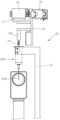
도 7은 본 발명에 의한 신체 자동 침습 장치의 주사침 유니트 가동부의 정면도.
도 8은 본 발명에 의한 신체 자동 침습 장치의 주사침 유니트 가동부의 측면도.
도 9는 본 발명에 의한 신체 자동 침습 장치의 프로브 유니트의 측면도.
도 10은 본 발명에 의한 신체 자동 침습 방법의 흐름도.
도 11은 도 10에 도시된 단계 중 타겟 신체부 탐지 방법의 흐름도.
도 12 내지 도 15는 타겟 혈관을 탐지하는 방법을 설명하기 위한 도면.1 is a block diagram of an automatic body invasion device according to the present invention.
2 is a front view of a slope adjusting unit of an automatic body invasion device according to the present invention;
3 is a side view of the slope adjustment unit of the automatic body invasion device according to the present invention.
4 is a side view of the transfer unit of the automatic body invasion device according to the present invention.
5 is a plan view of a transfer unit of the automatic body invasion device according to the present invention.
6 is a plan view of a slope adjustment unit according to another embodiment of the present invention.
7 is a front view of a movable part of a needle unit of an automatic body invasive device according to the present invention.
8 is a side view of the movable part of the needle unit of the automatic body invasive device according to the present invention.
9 is a side view of a probe unit of an automatic body invasion device according to the present invention.
10 is a flowchart of an automatic body invasion method according to the present invention.
11 is a flowchart of a method for detecting a target body part among steps shown in FIG. 10;
12 to 15 are views for explaining a method of detecting a target blood vessel;
이하에서는 첨부 도면을 참조하여 본 발명에 대해서 자세하게 설명한다.Hereinafter, the present invention will be described in detail with reference to the accompanying drawings.
본 명세서에서는 본 발명의 설명에 필요한 최소한의 구성요소만을 설명하며, 본 발명의 본질과 관계가 없는 구성요소는 언급하지 아니한다. 그리고 언급되는 구성요소만을 포함하는 배타적인 의미로 해석되어서는 아니되며 언급되지 않은 다른 구성요소도 포함할 수 있는 비배타적인 의미로 해석되어야 한다.In this specification, only the minimum components required for the description of the present invention are described, and components not related to the essence of the present invention are not mentioned. And it should not be interpreted as an exclusive meaning that includes only the mentioned components, but should be interpreted as a non-exclusive meaning that may include other components not mentioned.
본 명세서에서 설명하는 예시적인 실시예는 본 명세서에 개시(開示)되는 장치의 구조, 기능, 제작 및 용도와 방법의 원리에 대한 전반적인 이해를 제공한다. 이러한 하나 이상의 실시예가 첨부 도면에 도시되어 있다. 당업자라면 여기에 구체적으로 기재되고 첨부 도면에 도시되어 있는 장치 및 방법이 비제한적이고 예시적인 실시예이며 본 발명의 권리범위는 특허청구범위에 의해서 정의된다는 점을 이해할 것이다. 하나의 예시적인 실시예와 관련되어 도시되고 설명되는 특징은 다른 실시예의 특징과도 결합될 수 있다. 그러한 수정(modification) 또는 변경(variation)은 본 발명의 권리범위에 포함되도록 의도된다.The exemplary embodiments described herein provide a general understanding of the principles of the structure, function, fabrication and use of the devices and methods disclosed herein. One or more such embodiments are shown in the accompanying drawings. Those skilled in the art will understand that the devices and methods specifically described herein and illustrated in the accompanying drawings are non-limiting and illustrative examples, the scope of which is defined by the claims. Features shown and described in connection with one exemplary embodiment may also be combined with features of other embodiments. Such modifications or variations are intended to be included within the scope of the present invention.
본 발명의 설명에 있어서 각 단계의 순서는 선행 단계가 논리적 및 시간적으로 반드시 후행 단계에 앞서서 수행되어야 하는 경우가 아니라면 각 단계의 순서는 비제한적으로 이해되어야 한다. 즉 위와 같은 예외적인 경우를 제외하고는 후행 단계로 설명된 과정이 선행 단계로 설명된 과정보다 앞서서 수행되더라도 발명의 본질에는 영향이 없으며 권리범위 역시 단계의 순서에 관계없이 정의되어야 한다. 그리고 본 명세서에서 “A 또는 B”은 A와 B 중 어느 하나를 선택적으로 가리키는 것뿐만 아니라 A와 B 모두를 포함하는 것도 의미하는 것으로 정의된다. 또한, 본 명세서에서 "포함"이라는 용어는 포함하는 것으로 나열된 요소 이외에 추가로 다른 구성요소를 더 포함하는 것도 포괄하는 의미를 가진다.In the description of the present invention, the order of each step should be understood as non-limiting, unless the preceding step logically and temporally necessarily precedes the subsequent step. In other words, except for the above exceptional cases, even if the process described as the later step is performed before the process described as the preceding step, the essence of the invention is not affected, and the scope of rights must also be defined regardless of the order of the steps. And in this specification, "A or B" is defined to mean that it includes both A and B as well as selectively pointing to either one of A and B. In addition, in this specification, the term “including” has a meaning encompassing further including other components in addition to the elements listed as included.
본 발명에 의한 제어 방법은 컴퓨터, 태블릿 PC, 모바일폰, 휴대용 연산 장치, 고정식 연산 장치 등의 전자적 연산 장치에 의해서 실행될 수 있다. 또한, 본 발명의 하나 또는 그 이상의 방법 또는 형태가 적어도 하나의 프로세서에 의해 실행될 수 있다는 점이 이해되어야 한다. 프로세서는, 컴퓨터, 태블릿PC, 모바일 장치, 휴대용 연산 장치 등에 설치될 수 있다. 컴퓨터 프로그램 명령을 저장하도록 되어 있는 메모리가 그러한 장치에 설치되어서 프로그램이 저장된 프로그램 명령을 프로세서가 실행하도록 특별히 프로그램되어 하나 또는 그 이상의, 본 명세서에 기재된 기재된 바와 같은 프로세스를 실행할 수 있다. 또한, 본 명세서에 기재된 정보 및 방법 등은, 하나 또는 그 이상의 추가적인 구성요소와 프로세서를 포함하는 컴퓨터, 태블릿PC, 모바일 장치, 휴대용 연산 장치 등에 의해서 실행될 수 있다는 점이 이해되어야 한다. 또한, 제어 로직은, 프로세서, 제어부/제어 유니트 등에 의해 실행가능한 프로그램 명령을 포함하는 비휘발성 컴퓨터 판독 가능 매체로 구현될 수 있다. 컴퓨터 판독 가능 매체의 예로는, ROM, RAM, CD-ROM, 자기 테이프, 플로피 디스크, 플래시 드라이브, 스마트 카드, 광학 데이터 저장 장치 등이 있지만 그에 제한되는 것은 아니다. 또한, 컴퓨터 판독 가능 기록 매체는 네트워크로 연결된 컴퓨터에 분산되어, 컴퓨터 판독 가능 매체가 분산된 방식 예를 들어 원격 서버 또는 CAN(Controller Area Network)에 의해 분산된 방식으로 저장되고 실행될 수도 있다.The control method according to the present invention may be executed by an electronic arithmetic device such as a computer, tablet PC, mobile phone, portable arithmetic device, or stationary arithmetic device. Also, it should be understood that one or more methods or aspects of the invention may be executed by at least one processor. The processor may be installed in a computer, tablet PC, mobile device, portable computing device, or the like. A memory configured to store computer program instructions may be installed in such a device and may be specially programmed to cause a processor to execute the program instructions stored therein to execute one or more processes as described herein. In addition, it should be understood that the information and methods described in this specification may be executed by a computer, tablet PC, mobile device, portable computing device, etc. including one or more additional components and processors. In addition, the control logic may be implemented as a non-volatile computer readable medium including program instructions executable by a processor, a controller/control unit, or the like. Examples of computer readable media include, but are not limited to, ROM, RAM, CD-ROM, magnetic tape, floppy disk, flash drive, smart card, optical data storage device, and the like. In addition, the computer readable recording medium may be distributed to computers connected through a network, and the computer readable medium may be stored and executed in a distributed manner, for example, by a remote server or a controller area network (CAN).
도 1에는 본 발명에 의한 신체 자동 침습 장치의 블록도가 도시되어 있다. 도 1에 도시된 바와 같이 본 발명에 의한 신체 자동 침습 장치는 제어부(100)와, 사면(斜面) 조정부(22)와, 이송부(20)와, 주사침 유니트 가동부(30)와, 프로브 유니트(40)를 포함한다.1 is a block diagram of an automatic body invasion device according to the present invention. As shown in FIG. 1, the automatic body invasion device according to the present invention includes a
제어부(100)는, 사면 조정부(22)와, 이송부(20)와, 주사침 유니트 가동부(30)와, 프로브 유니트(40)의 동작을 제어한다. 제어부(100)는 전자적 연산 장치의 일부가 될 수 있으며, 범용적인 하드웨어와 그 기능을 수행하는 소프트웨어의 논리적 결합을 의미한다. 제어부(100)가 본 발명에 의한 신체 자동 침습 장치의 작동을 위해 생성하는 제어 명령은 전술한 컴퓨터 판독 가능 기록 매체에 저장된 컴퓨터 프로그램에 의해서 생성될 수 있다.The
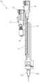
도 2에는 사면 조정부(22)의 정면도가 도 3에는 사면 조정부(22)의 측면도가 도시되어 있다.FIG. 2 shows a front view of the
사면 조정부(22)는 제1 구동 장치(16)와, 제1 방향 전환부(18)와, 제1 회전축(17)과, 몸체부(19)와, 제2 공압 장치(145)와, 지지암(14)과, 지지대(15)와, 검지부(222; 예를들어 비젼 센서)을 포함한다. 지지암(14)은 도 3에 도시된 바와 같이 서로 평행하게 제공되는 적어도 한 쌍의 암으로 제공될 수 있으며, 제2 공압 장치(145)에 의해서 서로를 향해 가까워지거나 멀어지는 방향으로 구동될 수 있다. 지지암(14)은 주사침 유니트(200)의 내측에서 서로 멀어지는 방향으로 이동하여 주사침 유니트(200)의 내벽에 외측 방사 방향으로 힘을 가하면서 주사침 유니트(200)를 지지할 수 있다. 주사침 유니트(200)의 주사침의 단부의 사면의 방향은 검지부(222)에 의해서 검지될 수 있다.The
지지대(15)에 제공된 주사침 유니트(200)의 검지된 사면의 방향이 소망하는 방향이 아닌 경우에는 제어부(100)의 제어 명령에 따라서 제1 구동 장치(16)가 구동하여 몸체부(19)를 제1 회전축(17)에 대해서 회전시켜서 지지암(14)에 의해 지지되어 있는 주사침 유니트(200)의 주사침 사면의 방향을 소망하는 방향으로 조정한다. 제1 구동 장치(16)의 구동력은 제1 방향 전환부(18)에 의해서 몸체부(19)를 회전시키는 방향으로 전환된다. 제1 구동 장치(16)의 구동력의 전달 방향을 전환하는 것은 공지되어 있는 다양한 기구학적 구조를 채택하여 구현할 수 있으며, 제1 방향 전환부(18)는 감속기를 포함할 수 있다. 본 명세서에서 후술하는 방향 전환부 역시 필요에 따라 감속기를 포함할 수 있다. 제1 구동 장치(16)는 회전 구동 장치 예를 들어 통상의 모터가 될 수도 있고, 또는 직선형 구동 장치 예를 들어 리니어 모터가 될 수도 있다. 리니어 모터를 사용하는 경우 제1 방향 전환부(18)는 직선 운동 방향을 지지암(14)을 회전시키는 회전 방향으로 전환한다.When the detected direction of the slope of the
사면 조정부(22) 뿐만 아니라 후술하는 다른 구성요소에 사용되는 방향 전환부는 필수적인 구성요소는 아니며 구동 장치의 설계에 따라서 사용되지 않을 수도 있다.The direction changing unit used for the
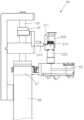
도 4 및 도 5에는 본 발명의 신체 자동 침습 장치의 이송부(20)의 측면도와 평면도가 각각 도시되어 있다. 도 4 및 도 5에 도시된 이송부(20)에는 본 발명의 다른 실시예에 의한 사면 조정부가 제공될 수 있다. 본 발명의 다른 실시예에 의한 사면 조정부의 평면도가 도 6에 도시되어 있다.4 and 5 show a side view and a plan view of the
이송부(20)는, 제2 구동 장치(23)와, 가동 암(24)과, 제2 회전축(25)과, 제1 본체부(26)와, 제2 방향 전환부(27)를 포함한다. 가동 암(24)에는 본 발명의 다른 실시예에 의한 사면 조정부가 제공될 수 있다. 이 사면 조정부는, 주사침 유니트(200)에 접하는 적어도 하나의 롤러(214)와, 롤러(214)를 회전시켜서 주사침 유니트(200)를 회전시키도록 되어 있는 제7 구동 장치(223)와, 검지부(222; 도 4 내지 도 6에는 도시되지 않음)를 포함할 수 있다. 주사침 유니트(200)는 제1 유지부(211)에 의해서 외측이 지지되어 소정의 위치를 유지할 수 있다. 제1 유지부(211)는 서로 평행한 적어도 한 쌍의 암을 포함할 수 있으며, 상기 암은 예를 들어 제3 공압 장치(215)에 의해서 서로 가까워지거나 멀어지는 방향으로 구동될 수 있다. 유지부(211)가 서로 가까워져서 주사침 유니트의 외측에 접하면 주사침 유니트(200)의 내측 방향으로 힘을 가해서 지지할 수 있다. 유지부(211)는 지지암(14)과 같이 주사침 유니트(200)의 내측에서 지지할 수도 있다.The
롤러(214)의 외주면에는 치부(齒部)가 제공되어 주사침 유니트(200)의 외주면에 접할 수 있다. 주사침 유니트(200)의 외주면에 상기 치부에 상보적인 치부가 제공되면 서로 치합하도록 접할 수 있다. 롤러(214)의 재질은 실리콘 또는 합성 수지 내지 금속이 될 수 있다.A tooth is provided on the outer circumferential surface of the
도 6에 도시된 사면 조정부는 주사침 유니트(200)가 롤러(214)의 회전에 의한 종속 회전 방향 이외의 방향으로는 주사침 유니트(200)가 움직이지 않도록 하는 이동 제한부(212, 213)을 더 포함할 수 있다. 이동 제한부(212, 213)는 주사침 유니트(200)의 외주에 복수 개가 제공될 수 있다.The slope adjusting unit shown in FIG. 6 further includes
가동 암(24)은, 제2 구동 장치(23)의 구동에 의해서 제1 위치와 제2 위치 사이에서 이동할 수 있다. 본 명세서에서 "제1 위치"라 함은, 주사침 유니트(200)가 이송부(20)에 제공되는 위치를 의미하며, "제2 위치"라 함은, 이송부(20)로부터 주사침 유니트 가동부(30)로 주사침 유니트(200)가 전달되는 위치를 의미한다. 사면 조정부(22)는 제1 위치에 인접하거나 제1 위치에 제공될 수도 있고, 제2 위치에 인접하거나 제2 위치에 제공될 수도 있다. 또는, 제1 위치와 제2 위치가 아닌 제3의 위치에도 제공될 수 있으며, 그러한 경우 가동 암(24)은 제1 위치로부터 제3 위치로 주사침 유니트(200)을 이송하여 제3 위치에서 사면 방향이 조정되고, 제3 위치로부터 제2 위치로 주사침 유니트(200)를 이송할 수 있다. 그러한 실시예에서는, 제1 위치로부터 제3 위치로 주사침 유니트(200)를 이송하는 가동 암과, 제3 위치로부터 제2 위치로 주사침 유니트(200)를 이송하는 가동 암은 별개로 구성될 수도 있다.The
사면 조정부(22)의 위치는 본 발명의 본질적인 기술적 사상과는 무관하다. 또는, 사면 조정부는 복수 개가 제공될 수도 있다. 사면 조정부가 제2 위치에 제공되는 경우에는 가동 암(24)은 필요하지 않을 수 있다.The position of the
도 7에는 본 발명에 의한 신체 자동 침습 장치의 주사침 유니트 가동부(30)의 정면도가, 도 8에는 측면도가 도시되어 있다.FIG. 7 shows a front view of the needle unit
주사침 유니트 가동부(30)는, 제2 본체부(31)와, 제1 공압 장치(32)와, 제3 구동 장치(33)와, 제4 구동 장치(34)와, 연결 부재(35), 제3 회전축(36)과, 제3 방향 전환부(37)를 포함한다.The needle unit
연결 부재(35)에는 주사침 유니트(200)가 지지되는데, 제1 공압 장치(32)에 의해 구동되는 적어도 한 쌍의 제2 유지부(321)에 의해서 지지될 수 있다.The
가동 암(24)이 제1 위치에서 제2 위치로 이동하면, 제2 위치에서 제1 공압 장치(32)의 작동에 의해서 제2 유지부(321)가 주사침 유니트(200)를 지지한 후에, 제3 공압 장치(215)의 작동에 의해서 유지부(211)와 주사침 유니트(200)와의 유지 상태가 해제됨으로써 주사침 유니트(200)가 전달될 수 있다. 주사침 유니트(200)가 전달된 후에, 가동 암(24)은 제1 위치로 복귀할 수 있다.When the
연결 부재(35)에 도 4 내지 도 6에 도시된 바와 같은 구성의 사면 조정부가 제공될 수도 있다. 주사침 유니트(200)가 도 7에 도시된 바와 같이 주사침 유니트 가동부(30)에 공급되고, 주사침 유니트 가동부(30)에 사면 조정부가 제공되는 실시예에서는 이송부(20)는 필요하지 않을 수 있다.The connecting
주사침 유니트(200)가 주사침 유니트 가동부(30)로 전달되어 제2 유지부(321)에 의해 지지된 상태에서, 제3 구동 장치(33)와 제4 구동 장치(34)에 의해서 신체 침습이 가능한 배향(orientation)으로 주사침 유니트(200)가 정렬되어 타겟 신체에 침습한다.In a state in which the
먼저, 제3 구동 장치(33)가 구동되어 제2 본체부(31)를 소정의 침습 가능 배향의 각도를 가지도록 제3 회전축(36)에 대해서 회전시킨다. 제3 구동 장치(33)의 구동력은 제3 방향 전환부(37)에 의해서 제3 회전축(36)에 대한 회전력으로 변환된다. 소정의 각도로 제2 본체부(31)가 회전한 상태에서, 제4 구동 장치(34)가 구동해서 연결 부재(35)를 제2 본체부(31)의 길이 방향을 따라서 이동시켜서 침습을 실행한다. 제2 본체부(31)의 길이 방향을 따라서 볼 스크류가 제공되어 연결 부재(35)가 이동할 수 있다.First, the
도 7과 도 8에는 도시되지 아니하였지만, 제2 본체부(31)는 도 7의 좌우 방향 및 도 8의 좌우 방향 중 적어도 어느 하나의 방향 또는 다른 방향으로 이동하도록 제공될 수 있다.Although not shown in FIGS. 7 and 8 , the second
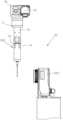
도 9에는 본 발명에 의한 프로브 유니트(40)의 측면도가 도시되어 있다.9 shows a side view of the
본 발명에 의한 프로브 유니트(40)는, 프로브(41)와, 프로브 지지부(42)와, 제5 구동 장치(43)와, 제6 구동 장치(44)와, 레일부(45)와, 가동부(46)와, 제4 방향 전환부(47)와, 타겟 신체를 누르도록 되어 있는 누름부(48)와, 누름부 홀더(485)를 포함한다. 프로브(41)는 예를 들어 초음파 프로브일 수 있다. 누름부(48)는 누름부 홀더(485)에 의해 회전 가능하게 지지될 수 있으며, 롤러 형태를 취할 수 있다. 누름부(48)와 프로브 지지부(42)는 탄성 부재(49; 예를 들어 스프링)에 의해서 서로 연결되어 누름부(48)가 소정의 힘으로 신체를 누를 수 있도록 할 수 있다.The
제5 구동 장치(43)의 작동에 의해 프로브 지지부(42)는 제4 회전축(475)에 대해서 회전할 수 있다. 제5 구동 장치(43)의 구동력은 제4 방향 전환부(47)에 의해서 프로브 지지부(42)를 제4 회전축(475)에 대해 회전시키는 회전력으로 전환될 수 있다.The
가동부(46)는, 제6 구동 장치(44)의 작동에 의해서 레일부(45)의 길이 방향을 따라서 이동할 수 있다. 레일부(45)에는 볼 스크류가 제공될 수 있다.The
프로브 유니트(40)는 신체(400)의 길이 방향으로 이동할 수 있다. 타겟 신체(예를 들어 표재 정맥)의 위치를 탐지하는 방법의 예시는 후술한다. 타겟 신체이 혈관인 경우, 직선화를 한 후에 탐지하면 위치 탐지가 수월해지므로, 프로브 유니트(40)를 신체 지지부(300)에 놓인 신체(400; 예를 들어 하완)의 길이 방향을 따라서 이동시키면서 누름부(48)가 신체를 눌러서 직선화시킬 수 있다. 한편, 누름부(48)가 직선화를 위해 누르는 범위는 타겟 신체 탐지를 위해 유의미한 거리로 미리 결정된 범위 내로 설정할 수 있다.The
다음으로 본 발명의 작동 및 제어 방법에 대해서 도 10 및 도 11 그리고 도 1 내지 도 9를 참조하여 설명한다.Next, the operation and control method of the present invention will be described with reference to FIGS. 10 and 11 and FIGS. 1 to 9 .
단계(1100)에서 주사침 유니트(200)가 공급된다. 주사침 유니트(200)는 사면 조정부(22)에 공급될 수 있다. 도 2 및 도 3에 도시된 실시예에서는 지지대(15)에 주사침 유니트(200)가 지지되도록 공급할 수 있다. 도 4 내지 도 6에 도시된 사면 조정부의 실시예에서는 주사침 유니트(200)가 유지부(211)에 의해 지지되고 롤러(214) 사이에 배치되도록 주사침 유니트(200)를 공급할 수 있다. 전술한 바와 같이 사면 조정부는 제1 위치 및 제2 위치 중 적어도 어느 하나 또는 인접하여 제공될 수 있고, 제1 위치 또는 제2 위치가 아닌 제3의 위치 또는 인접하도록 제공될 수도 있다.In
주사침 유니트(200)가 공급되면, 검지부(222)가 주사침의 사면의 방향 및 단부의 위치를 인식한다(단계 1110). 인식한 주사침 사면의 방향이 설정된 방향과 다르면 제어부(100)의 명령을 제1 구동 장치(16) 또는 제7 구동 장치(223)가 수신하여 작동하여 주사침 유니트(200)를 회전시킴으로써 주사침의 사면 방향을 조정한다(단계 1120). 제1 구동 장치(16)가 작동하면 제1 회전축(17)에 대해서 몸체부(19)가 회전하고, 지지암(14)에 의해 지지되어 있는 주사침 유니트(200)가 회전한다.When the
도 4 내지 도 6에 도시된 다른 실시예의 사면 조정부에 있어서는, 제7 구동 장치(223)가 작동하면 롤러(214)가 회전하고, 그에 의해서 주사침 유니트(200)가 회전하여 사면 방향이 조정된다.In the slope adjusting unit of another embodiment shown in FIGS. 4 to 6 , when the
검지부(222)에 의해 조정된 주사침의 사면 방향이 설정된 값에 도달하면 제1 구동 장치(16) 또는 제7 구동 장치(223)의 작동을 멈추고 조정된 주사침 사면의 위치 정보를 제어부(100)에 기록된 값과 동기화를 시킨다(단계 1130).When the slope direction of the needle adjusted by the
다음으로 타겟 신체의 위치를 선정한다(단계 1140). 타겟 신체가 표재 정맥인 경우의 선정 과정이 도 11에 도시되어 있다.Next, the position of the target body is selected (step 1140). A selection process when the target body is a superficial vein is shown in FIG. 11 .
먼저 프로브(41)를 혈관 근처로 이동시킨다(단계 1141). 이어서 누름부(48)로 혈관을 누른 상태로 프로브 유니트(40)를 이동시켜 직선화를 시행한다(단계 1142). 누름부(48)는 타겟 신체의 소정의 범위만큼만 이동하게 할 수 있다. 누름부(48)로 혈관을 직선화하면 초음파 스캔 및 채혈이 용이해진다. 누름부(48)가 누르는 힘은 0 내지 19.6N의 범위에서 최적화된 일정한 힘으로 누르도록 할 수 있다.First, the
혈관 직선화가 완료되면 프로브(41)를 타겟 신체에 접촉시키고 초음파 영상을 획득하며(단계 1143), 획득한 초음파 영상의 이미지 처리를 통해 타겟 혈관의 위치를 결정한다(단계 1144).When blood vessel straightening is completed, the
타겟 신체의 위치가 표재 정맥인 경우의 위치 선정의 구체적인 예시적인 실시예는 도 12 내지 도 15를 참조하여 후술한다. Specific exemplary embodiments of location selection when the location of the target body is the superficial vein will be described later with reference to FIGS. 12 to 15 .
단계(1150)에서 주사침 유니트(200)를 제2 위치로 이동한다. 사면 조정부(22)가 제1 위치 또는 제1 위치에 인접하여 배치되는 경우에는 사면 방향이 조정된 주사침 유니트(200)를 가동 암(24)이 지지한 상태에서, 제어부(100)의 명령을 받아 제2 구동 장치(23)가 작동하여 가동 암(24)을 제2 회전축에 대해 회전시켜 제1 위치에서 제2 위치로 이동할 수 있다. 제1 위치에서 제2 위치로의 이동이 반드시 가동 암(24)의 회전을 통해서만 이루어질 필요는 없으며, 공지되어 있거나 공지되어 있는 구조로부터 당업자에게 자명한 사항의 기구학적 위치 변경 구조라면 어느 것이든 적용할 수 있다.In
사면 조정부(22)가 제2 위치 또는 제2 위치에 인접하여 배치되는 경우에는, 단계(1150)은 불필요할 수 있다. 이 실시예에서는, 주사침 유니트 가동부(30)에 주사침 유니트(200)가 지지된 상태에서 도 2 및 도 3 또는 도 4 내지 도 6에 도시된 사면 조정부가 사면 방향을 조정하면 된다.
사면 조정부(22)가 제3의 위치에 제공되는 경우에는, 가동 암(24)이 제1 위치에서 제3 위치로 이동하고, 제3 위치에서 사면 방향을 조정한 후에, 제2 위치로 이동할 수 있다.When the
제2 위치에서 주사침 유니트(200)가 주사침 유니트 가동부(30)에 지지된 상태에서, 제3 구동 장치(33)가 제어부(100)의 명령에 따라 작동하여 제2 본체부(31)를 소정의 각도 즉 신체 침습을 위한 각도로 회전시키고, 제4 구동 장치(34)가 제어부(100)의 명령을 받아 연결 부재(35)를 제2 본체부(31)의 길이 방향을 따라 이동시켜 신체 침습을 시행한다. 타겟 신체가 표재 정맥인 경우에는 침습 후 채혈을 실시할 수 있다. 도 7과 도 8에는 도시되지 아니하였지만, 제2 본체부(31)는 도 7의 좌우 방향 및 도 8의 좌우 방향 중 적어도 어느 하나의 방향 또는 다른 방향으로 이동하도록 제공될 수 있다.In the state where the
이하에서는, 초음파 프로브(41)에 의해 획득한 영상 이미지를 처리하여 침습할 신체부(표재 정맥을 예시로 설명)의 위치를 탐지하는 방법의 예에 대해서 설명한다. 이하에서 설명하는 탐지 방법은, 본 출원인의 특허출원 제10-2020-0010302호에 기재된 내용이며, 본 발명의 이해를 돕기 위해 설명하는 예시적인 용도로서만 의미가 있으며 본 발명의 권리범위를 제한하지 않는다.Hereinafter, an example of a method of detecting a location of a body part to be invaded (a superficial vein will be described as an example) by processing a video image acquired by the
도 12에는 프로브 탐지를 통해 표재 정맥 위치 결정 방법의 흐름도가 도시되어 있다.12 shows a flow chart of a method for determining superficial vein location via probe detection.
표재 정맥의 위치 탐색을 위해선 피검자가 먼저 상완 압박 유니트(도시되지 않음)에 상완을 넣고 상완 압박을 수행한다(단계 1200). 상완 압박 유니트는 1 내지 5cm의 압박 수단을 포함하며, 압박 수단은 팔꿈치 위쪽 3 내지 12 cm, 바람직하게는 6 내지 8 cm에서 상완을 압박한다. 압박 압력은 10 내지 60 mmHg, 바람직하게는 20 내지 30 mmHg의 압력일 수 있다. 상완 압박 유니트가 상완을 압박하지 않고 후술하는 과정을 수행해도 무방하다.In order to search for the location of the superficial vein, the subject first puts the upper arm in a brachial compression unit (not shown) and performs upper arm compression (step 1200). The upper arm compression unit includes a compression means of 1 to 5 cm, and the compression means compresses the upper arm at 3 to 12 cm above the elbow, preferably 6 to 8 cm. Compression pressure may be 10 to 60 mmHg, preferably 20 to 30 mmHg. It is okay for the upper arm compression unit to perform the process described below without compressing the upper arm.
도 12에는 상완 압박이 초음파 프로브(41)의 이동 전에 수행되는 것으로 도시되어 있지만, 초음파 프로브(41)를 이동시킨 후에 초음파 프로브(41)가 제1 영상 데이터 획득을 시작한 후에 상완 압박이 수행될 수도 있다. 제1 영상 데이터 획득을 시작한 후에 상완 압박을 수행하는 경우에는, 상완 압박 수행 전의 제1 영상 데이터와, 상완 압박 수행 후의 제1 영상 데이터를 획득할 수 있다.12 shows that the upper arm compression is performed before moving the
도 12로 돌아오면, 상완 압박 후에 피검자의 신체로부터 소정의 거리 예를 들어 1mm 만큼 이격된 위치로 초음파 프로브(41)를 이동시킨다(단계 1205).Returning to FIG. 12 , after upper arm compression, the
초음파 프로브(41)가 배치되는 피검자의 신체 위치는, 팔오금중간정맥(median cubital vein)이 위치하는, 팔 오금으로부터 손 방향으로 0 내지 8 cm, 바람직하게는 1 내지 3 cm일 수 있다.A body position of the subject where the
단계(1210)에서는 초음파 프로브(41)를 피검자의 신체쪽으로 이동시키면서 제1 영상 데이터를 획득한다. 제1 영상 데이터는, 피검자의 신체에 초음파 프로브(41)가 접촉하기 전의 영상 데이터이며, 상완이 압박되기 전의 영상 데이터와 상완이 압박된 후의 영상 데이터를 포함할 수 있다.In
초음파 프로브(41)가 피검자의 신체에 접촉하고 압박하는 동안에는 제2 영상 데이터가 수집된다. 본 발명의 다른 실시예에 의하면 초음파 프로브(41)가 아닌 다른 수단에 의해서 피검자의 신체가 압박될 수도 있다.Second image data is collected while the
제1 및 제2 영상 데이터는 혈류의 음파 신호 중 도플러 효과를 통해 분석된 영상 데이터를 포함할 수 있다. 본 발명의 다른 실시예에 의하면 제1 영상 데이터 및 제2 영상 데이터 중 어느 하나만 사용할 수도 있다.The first and second image data may include image data analyzed through a Doppler effect among sound wave signals of blood flow. According to another embodiment of the present invention, only one of the first image data and the second image data may be used.
획득된 제1 및 제2 영상 데이터는 영상 데이터 처리 모듈(30)에 의해서 본 발명에 의한 방법을 실행하는 프로그램이 사용할 수 있는 포맷과 크기로 변환된다(단계 1220). 본 발명의 다른 실시예에 의하면 영상 데이터의 변환 없이 후술하는 영상 데이터 분석이 수행될 수 있다.The acquired first and second image data are converted into a format and size usable by a program executing the method according to the present invention by the image data processing module 30 (step 1220). According to another embodiment of the present invention, image data analysis described below may be performed without conversion of image data.
기계 학습 서버(140)의 예를 들어 컨볼루션 신경망을 통해서, 변환된 영상 데이터를 분석해서 영상 데이터에 목적 타겟과 회피 타겟의 픽셀을 표시한다(단계 1225).The converted image data is analyzed by the machine learning server 140, for example, through a convolutional neural network, and pixels of a target target and an avoidance target are displayed in the image data (step 1225).
본 명세서에서 목적 타겟은 표재 정맥 또는 동맥과 같은 혈관을, 회피 타겟은 동맥, 신경, 뼈 조직 등을 의미하며, 용도에 따라서 목적 타겟과 회피 타겟이 결정될 수 있다. 예를 들어 용도에 따라서는, 표재 정맥 위치 확인시 회피 타겟으로 결정되는 동맥이나, 신경, 뼈 조직 등이 오히려 목적 타겟으로 설정될 수도 있다.In the present specification, a target target refers to a blood vessel such as a superficial vein or artery, and an avoidance target refers to an artery, nerve, bone tissue, and the like. For example, depending on the purpose, an artery, nerve, bone tissue, etc., which are determined as avoidance targets when checking the location of a superficial vein, may be set as the target target.
목적 타겟과 회피 타겟을 표시하는 방법은, 픽셀 단위로 표시될 수 있으며, 중앙 값과 경계 및 거리를 통해서 bound-box로 표시될 수도 있다. 또는, 중앙 값, 원형/타원형, 직사각형 등 형태에 대한 정보와, 반지름/두 지점 이상의 거리 정보/한 변의 길이 등 형태를 특정할 수 있는 정보를 함께 저장할 수도 있다.A method of displaying the target target and the avoidance target may be displayed in pixel units, or may be displayed as a bound-box through a central value, a boundary, and a distance. Alternatively, information about the shape, such as a center value, circle/ellipse, or rectangle, and information for specifying the shape, such as radius/distance information of two or more points/length of one side, may be stored together.
본 발명에서 활용하기 위한 기계 학습의 일례인 컨볼루션 신경망 학습에 대해서 설명한다.Convolutional neural network learning, which is an example of machine learning for use in the present invention, will be described.
컨볼루션 신경망 학습을 위해서는 사전에 학습 데이터를 통한 학습을 수행해야 한다. 컨볼루션 신경망 학습에 사용되는 영상 데이터는 전술한 바와 같은 제1 및 제2 영상 데이터의 랜덤 크롭, 크기 변환, 수평 플립 등을 포함하는 데이터 증강 기법으로 데이터의 일반성을 증가시키도록 전처리될 수 있다.In order to learn a convolutional neural network, it is necessary to perform learning through training data in advance. Image data used for learning the convolutional neural network may be preprocessed to increase the generality of the data using a data augmentation technique including random cropping, resizing, and horizontal flipping of the first and second image data as described above.
기계 학습 서버는 컨볼루션 신경망 학습을 통해서 목적 타겟과 회피 타겟의 특징에 부합하는 정보를 획득하고 저장한다.The machine learning server acquires and stores information corresponding to the characteristics of the goal target and the avoidance target through convolutional neural network learning.
그러한 특징 정보에는, 초음파 영상 데이터에서 확인되는 성분들이 가지는 echogenicity의 세기, echogenic한 성분들이 분포하는 패턴 정보, 영상 데이터내에서 확인되는 성분들이 분포하는 상대적인 위치 정보, 피검자의 키, 체중, 성별, 나이, 이환된 질환, 과거에 받았거나 현재 받고 있는 치료 정보, 초음파 프로브 또는 다른 수단에 의해서 압박될 때의 정보, 도플러 영상을 통해 분석한 혈류의 실시간 흐름 정보 중 적어도 어느 하나를 포함할 수 있다.Such feature information includes the intensity of echogenicity of components identified in ultrasound image data, pattern information of distribution of echogenic components, relative location information of distribution of components identified in image data, subject's height, weight, gender, and age. , afflicted diseases, past or current treatment information, information when compressed by an ultrasound probe or other means, and real-time flow information of blood flow analyzed through Doppler images.
압박될 때의 정보는, 초음파 프로브 또는 다른 수단으로 피부 표면을 누르면 동맥과 달리 정맥은 직접 압박되어 크기가 줄어들거나 근위부가 압박되어 울혈이 유발됨으로써 크기가 부풀게 되는데 그에 관한 정보를 포함할 수 있다.The information at the time of compression, unlike arteries, when the skin surface is pressed with an ultrasound probe or other means, veins are directly compressed and reduced in size, or compressed in the proximal portion to cause congestion and swell in size. It may include information about it.
혈류의 실시간 정보는, 회피 타겟의 하나인 동맥의 경우 정맥과 달리 혈류가 빨라서 도플러 신호가 강하고 주기적으로 커지고 작아지며 박동을 하기 때문에 타겟 탐지에 유용하다.Real-time information of blood flow is useful for target detection because arteries, which are one of the avoidance targets, have fast blood flow, so Doppler signals are strong and periodically increase and decrease and pulsate, unlike veins.
컨볼루션 신경망 학습은, 상기 특징 정보를 바탕으로 영상 데이터 내에서 목적 타겟과 회피 타겟의 위치에 대응하는 픽셀을 표시하도록 훈련할 수 있다.Convolutional neural network learning may be trained to display pixels corresponding to locations of a target target and an avoidance target within image data based on the feature information.
상기 학습(훈련)은 예를 들어 지도 학습(supervised learning), 비지도 학습(unsupervised learning), 반지도 학습(semi-supervised learning)일 수 있다.The learning (training) may be, for example, supervised learning, unsupervised learning, or semi-supervised learning.
지도 학습의 경우 정답이 있는 영상과 비교하면서 훈련할 수 있는데 정답과 컨볼루션 신경망이 찾은 목적 타겟 및 회피 타겟이 다른 경우에는 손실 함수의 손실을 감소시키는 방향으로 학습시킬 수 있다. 손실 함수는 BCEloss(Binary Cross Entropy loss), Crossentropy 등이 될 수 있으며, 옵티마이저(optimizer)는 adam, RMSprop, 확률적 경사하강법을 사용할 수 있다. 그리고 평가는 dice coefficient loss 등을 통해서 수행할 수 있다.In the case of supervised learning, training can be performed while comparing with an image with the correct answer. If the correct answer and the target target and avoidance target found by the convolutional neural network are different, the loss function can be trained in a direction that reduces the loss. The loss function can be BCEloss (Binary Cross Entropy loss) or Crossentropy, and the optimizer can use adam, RMSprop, or stochastic gradient descent. And evaluation can be performed through dice coefficient loss, etc.
컨볼루션 신경망 학습과 같은 기계 학습을 통해 목적 타겟과 회피 타겟이 결정되면, 단계(1230)로 이행하여 최종 목적 타겟을 결정한다.When the target target and the avoidance target are determined through machine learning such as convolutional neural network learning, the process proceeds to step 1230 to determine the final target target.
도 13에는 단계(1230)의 구체적인 과정의 흐름도가 도시되어 있다.13 shows a flowchart of a specific process of
단계(1300)에서는 단계(1225)에서 찾은 목적 타겟이 존재하는지 여부를 판단한다. 목적 타겟이 존재하면 단계(1305)로 이행하여 탐색된 목적 타겟이 1개인지, 2개 이상인지를 판단한다. 먼저 목적 타겟이 한 개인 경우에 대해서 설명한다.In
목적 타겟이 한 개인 경우 해당 목적 타겟의 경계가 영상 데이터의 경계에 겹치는지를 판단한다(단계 1335). 겹치지 않으면 단계(1310)으로 이행하고, 겹치는 경우에는 단계(1355)로 이행하여 경계면 좌표가 영상 데이터의 내측 예를 들어 중앙에 위치하도록 초음파 프로브(41)를 이동하고 단계(1210)으로 복귀하여 그 이후의 절차를 수행한다. 초음파 프로브(41)를 이동하지 않고 피검자의 신체를 이동하게 할 수도 있다.If there is only one target target, it is determined whether the boundary of the target target overlaps the boundary of the image data (step 1335). If they do not overlap, go to
단계(1310)에서는 목적 타겟의 크기 기반 정보 중 하나인 최대 내접원 직경을 산출한다. 최대 내접원은, 목적 타겟의 픽셀만 들어갈 수 있는 원 중에서 크기가 가장 큰 내접원을 의미한다. 목적 타겟의 크기 기반 정보는 최대 내접원 직경 이외에 목적 타겟 내에 그릴 수 있는 가로선과 세로선의 최대 및 최소 길이, 목적 타겟의 무게 중심으로부터 목적 타겟의 경계선까지의 최대 및 최소 거리, 목적 타겟의 면적 등의 다른 정보가 될 수 있다.In
그리고 목적 타겟의 깊이 기반 정보인 깊이를 산출하고(단계 1315), 제1 판단 기준과 제2 판단 기준을 해당 목적 타겟이 만족하는지 여부를 판단한다(단계 1320). "깊이 기반 정보"는 단순한 깊이 뿐만 아니라 깊이와 관련된 다양한 다른 정보들도 포함한다.Then, depth, which is depth-based information of the target target, is calculated (step 1315), and it is determined whether the corresponding target target satisfies the first and second criteria (step 1320). "Depth-based information" includes not only simple depth, but also various other information related to depth.
목적 타겟이 표재 정맥인 경우, 제1 판단 기준은, 최대 내접원 직경이 소정의 값(제1 값)보다 크거나 또는 같은지 여부를 판단하는 기준이다. 제1 값은, 기기 작동 오차 범위 내에서 결정될 수 있다. 예를 들어, 최대 내접원 직경이 2 mm 미만인 경우라면 해당 목적 타겟은 회피 타겟으로 분류할 수 있다(단계 1375). 제1 값보다 최대 내접원 직경이 크거나 또는 같으면 제1 판단 기준을 만족하는 것으로 판단한다.When the target target is a superficial vein, the first criterion is a criterion for determining whether the maximum inscribed circle diameter is greater than or equal to a predetermined value (first value). The first value may be determined within an operating error range of the device. For example, if the maximum inscribed circle diameter is less than 2 mm, the target target may be classified as an avoidance target (step 1375). If the maximum inscribed circle diameter is greater than or equal to the first value, it is determined that the first criterion is satisfied.
크기 기반 정보가 목적 타겟 내에 그릴 수 있는 가로선과 세로선의 길이 정보인 경우, 가로선과 세로선의 최대 및 최소 길이가 각각 소정의 값보다 크거나 또는 같은지 여부를 판단하는 것이 제1 판단 기준이 될 수 있다. 예를 들어, 가로선과 세로선의 최소 길이가 2 mm 미만인 경우에 목적 타겟을 회피 타겟으로 분류할 수 있다. 목적 타겟이 단수가 아닌 경우에는 가로선과 세로선들의 합, 곱, 평균 등이 더 큰 목적 타겟을 최종 목적 타겟 후보로 선정할 수도 있으며(단계 1370).When the size-based information is information on the lengths of horizontal and vertical lines that can be drawn within the target target, the first criterion may be to determine whether the maximum and minimum lengths of the horizontal and vertical lines are greater than or equal to a predetermined value, respectively. . For example, when the minimum length of the horizontal line and the vertical line is less than 2 mm, the target target may be classified as an avoidance target. If the target target is not singular, a target target having a greater sum, product, or average of horizontal and vertical lines may be selected as a final target target candidate (step 1370).
크기 기반 정보가 목적 타겟의 무게 중심으로부터 경계선까지의 최대 및 최소 거리인 실시예에서는, 상기 최대 및 최소 거리가 소정의 값보다 크거나 같은지 여부를 판단하는 기준이 제1 판단 기준이 될 수 있다. 예를 들어, 목적 타겟의 무게 중심으로부터 목적 타겟의 경계선까지의 최소 거리가 2mm 미만인 경우에 목적 타겟을 회피 타겟으로 분류할 수 있다. 목적 타겟이 복수 개인 경우 무게 중심으로부터 목적 타겟 경계선까지의 거리들의 합, 곱, 평균 등이 더 큰 목적 타겟을 최종 목적 타겟 후보로 선정할 수 있다(단계 1370).In an embodiment in which the size-based information is the maximum and minimum distances from the center of gravity of the target target to the boundary line, a criterion for determining whether the maximum and minimum distances are greater than or equal to a predetermined value may be the first criterion. For example, when the minimum distance from the center of gravity of the target target to the boundary of the target target is less than 2 mm, the target target may be classified as an avoidance target. When there are a plurality of target targets, a target target having a greater sum, product, or average of distances from the center of gravity to the target boundary line may be selected as a final target target candidate (step 1370).
크기 기반 정보가 면적 정보인 실시예에서는, 면적이 소정의 값보다 크거나 또는 같은지 여부를 판단하는 기준이 제1 판단 기준이 될 수 있다. 예를 들어, 목적 타겟의 면적이 10mm2 미만인 경우에 해당 목적 타겟을 회피 타겟으로 분류할 수 있으며, 목적 타겟이 복수 개인 경우에는 면적이 더 큰 목적 타겟을 최종 목적 타겟 후보로 선정할 수 있다(단계 1370)In an embodiment in which the size-based information is area information, a criterion for determining whether the area is greater than or equal to a predetermined value may be the first criterion. For example, when the area of the target target is less than 10 mm2 , the corresponding target target may be classified as an avoidance target, and when there are a plurality of target targets, a target target having a larger area may be selected as a final target target candidate ( step 1370)
제2 판단 기준은, 목적 타겟의 깊이가 소정의 값(제2 값) 예를 들어, 1cm 보다 작거나 또는 같은지 여부를 판단하는 기준이다. 목적 타겟의 깊이가 제2 값보다 깊으면 해당 목적 타겟은 회피 타겟으로 결정한다(단계 1375). 이는, 표재 정맥이 아니라 심부 정맥의 경우 표재 정맥보다 지혈이 어렵기 때문에 배제하고, 회피 타겟인 동맥 역시 배제하기 위함이다. 그리고 제2 값보다 깊은 경우 주사침이 진입하다가 상처를 깊게 낼 수 있으며, 그 침습 경로 내에 중요한 해부학적 구조물 내지 신경이 있을 수 있기 때문에 제2 판단 기준을 적용한다. 목적 타겟의 깊이가 제2 값보다 같거나 또는 작으면 제2 판단 기준을 통과한 것으로 판단한다.The second criterion is a criterion for determining whether the depth of the target target is less than or equal to a predetermined value (second value), for example, 1 cm. If the depth of the target target is greater than the second value, the corresponding target target is determined as an avoidance target (step 1375). This is to exclude deep veins rather than superficial veins because hemostasis is more difficult than superficial veins, and also to exclude arteries, which are avoidable targets. If the depth is greater than the second value, the second criterion is applied because the injection needle may cause a deep wound while entering, and there may be important anatomical structures or nerves in the invasion path. If the depth of the target target is equal to or smaller than the second value, it is determined that the second criterion is passed.
제1 판단 기준과 제2 판단 기준을 만족하면, 목적 타겟과 피부 표면 사이의 직선 경로에 회피 타겟이 존재하는지 여부를 판단한다(단계 1325; 제3 판단 기준). 직선 경로에 회피 타겟이 존재하면 그 회피 타겟은 팔의 측면의 신경일 수가 있다.If the first criterion and the second criterion are satisfied, it is determined whether an avoidance target exists in the straight path between the target target and the skin surface (
단계(1325)의 판단 결과 "아니오"이면 해당 목적 타겟을 최종 목적 타겟으로 결정한다(단계 1330).If the decision result of
제1 판단 기준 내지 제3 판단 기준 중 모든 기준을 만족할 때 최종 목적 타겟으로 결정할 수도 있지만, 제1 판단 기준 내지 제3 판단 기준 중 적어도 어느 하나를 만족하면 최종 목적 타겟으로 결정할 수도 있다.The final destination target may be determined when all of the first to third determination criteria are satisfied, but the final target may be determined when at least one of the first to third determination criteria is satisfied.
단계(1225)에서 탐색된 목적 타겟이 복수인 경우에 대해서 설명한다.A case where a plurality of target targets searched in
목적 타겟이 복수개 탐색되면 단계(1360)으로 이행하여 목적 타겟 각각의 최대 내접원 크기를 산출한다. 그리고 각각의 최대 내접원 크기를 비교하고(단계 1365), 제3 판단 기준에 따라서 최종 목적 타겟의 후보를 선정한다(단계 1370).When a plurality of target targets are searched for, the process proceeds to step 1360 to calculate the maximum inscribed circle size of each target target. Then, each maximum inscribed circle size is compared (step 1365), and a final target candidate is selected according to a third criterion (step 1370).
제3 판단 기준은 다음과 같다. 최대 내접원의 크기가 가장 큰 목적 타겟을 최종 목적 타겟의 후보로 선정하는 것이 원칙이되, 그 다음으로 큰 최대 내접원을 가지는 목적 타겟의 내접원과의 크기 차이가 소정의 값(제3 값) 예를 들어 10% 이내인 경우에는 초음파 프로브의 접촉면으로부터 가까운 예를 들어, 초음파 프로브의 접촉면의 중앙 지점으로부터 가까운 목적 타겟을 최종 목적 타겟의 후보로 결정할 수 있다.The third criterion is as follows. In principle, a target target having the largest maximum inscribed circle size is selected as a candidate for the final target target, but the size difference between the target target having the next largest inscribed circle and the target target having the largest inscribed circle size is a predetermined value (third value). For example, within 10%, a target target close to the contact surface of the ultrasonic probe, for example, close to the central point of the contact surface of the ultrasonic probe may be determined as a final target target candidate.
최대 내접원 크기가 아닌 다른 크기 기반 정보를 제1 정보로 사용하는 경우에도, 비교값의 차이가 소정의 값 이내라면 초음파 프로브의 접촉면으로부터 가까운 예를 들어, 초음파 프로브의 접촉면의 중앙 지점으로부터 가까운 목적 타겟을 최종 목적 타겟의 후보로 결정할 수 있다.Even when size-based information other than the size of the maximum inscribed circle is used as the first information, if the difference between the comparison values is within a predetermined value, the target target is close to the contact surface of the ultrasonic probe, for example, close to the center point of the contact surface of the ultrasonic probe. may be determined as a candidate for the final target.
단계(1370)에서 최종 목적 타겟의 후보가 결정되면 단계(1315)로 이행하여 전술한 그 이후의 과정이 실행되어 최종 목적 타겟이 결정되거나 회피 타겟으로 결정된다.When the candidate for the final target is determined in
단계(1300)에서 목적 타겟이 존재하지 않는 것으로 판단되는 경우에는 목적 타겟 탐색이 소정 횟수 이상인지를 판단한다. 소정의 횟수 예를 들어 2회 또는 3회 이상인 경우에는 단계(1380)로 이행하여 반대쪽 팔에 대해서 목적 타겟을 탐색하도록 한다. 소정의 횟수 미만이면 단계(1210)로 이행하여 초음파 프로브(41)를 이동시켜 제1 영상 데이터를 획득하도록 한다. 이 때 이전 영상과 겹치지 않는 위치로 초음파 프로브(41)를 이동시켜서 제1 영상 데이터를 획득하도록 한다.In
상기 과정을 거쳐서 최종 목적 타겟이 결정되면 단계(1235)에서 최종 목적 타겟의 중심 좌표를 산출한다. 주사침 유니트(200)는 중심 좌표로 침습을 수행한다.When the final target is determined through the above process, in
중심 좌표는 최종 목적 타겟의 픽셀만을 포함하는 최대 내접원 내부의 임의의 지점(xi)와의 거리가 최대인 지점(x)의 좌표로 결정된다.The center coordinate is determined as the coordinate of a point (x) at the maximum distance from an arbitrary point (xi ) inside the maximum inscribed circle including only pixels of the final target target.
중심 좌표 산출이 완료된 후에, 해당 중심 좌표와 피부 표면 사이의 직선 경로 내에, 혈관의 표면을 소정의 횟수 예를 들어 2번 이상 지나는 경우에는 해당 최종 목적 타겟을 배제할 수 있다.After the calculation of the central coordinates is completed, if the blood vessel surface is passed a predetermined number of times, for example, two or more times within a linear path between the corresponding central coordinates and the skin surface, the final target target may be excluded.
한편, 최종 목적 타겟 내의 모든 픽셀에 대해서 소정의 직경 예를 들어 1 mm의 직경을 가지는 원을 그리고, 그 원 내부의 픽셀 중 소정의 비율 예를 들어 30 내지 95% 바람직하게는 50 내지 70%이상의 픽셀이 최종 목적 타겟으로 분류되는 경우에 해당 픽셀을 최종 목적 타겟으로 하고, 그렇지 않으면 해당 픽셀은 삭제한다.On the other hand, a circle having a predetermined diameter, for example, 1 mm is drawn for all pixels in the final target target, and a predetermined ratio, for example, 30 to 95%, preferably 50 to 70% or more of the pixels inside the circle is drawn. If a pixel is classified as an end-target, then that pixel is the end-target; otherwise, the pixel is deleted.
도 15에 도시된 바와 같이, 픽셀(1510)을 기준으로 그린 원(1520) 내에는 모든 픽셀(소정 비율 이상)이 존재하므로 해당 픽셀(1510)은 최종 목적 타겟의 픽셀로 분류될 수 있다. 픽셀(1530)을 기준으로 그린 원(1511) 내에는 최종 목적 타겟의 픽셀이 아닌 픽셀이 소정 비율 이상 존재하지 않으므로 해당 픽셀(1530)은 최종 목적 타겟에서 제거될 수 있다.As shown in FIG. 15 , since all pixels (more than a predetermined ratio) exist in a
이 과정은 최종 목적 타겟의 경계면을 부드럽게 만들고 잘못 분류될 수 있는 픽셀이 존재할 가능성을 배제하고자 하는 과정이지만, 본 발명의 실시에 반드시 필요한 과정은 아니고 부수적인 과정이다.This process is a process for smoothing the boundary surface of the final target target and excluding the possibility of pixels that may be misclassified.
이상 첨부 도면을 참고하여 본 발명에 대해서 설명하였지만 본 발명의 권리범위는 후술하는 특허청구범위에 의해 결정되며 전술한 실시예 및/또는 도면에 제한되는 것으로 해석되어서는 아니된다. 그리고 특허청구범위에 기재된 발명의, 당업자에게 자명한 개량, 변경 및 수정도 본 발명의 권리범위에 포함된다는 점이 명백하게 이해되어야 한다.Although the present invention has been described with reference to the accompanying drawings, the scope of the present invention is determined by the claims described below and should not be construed as being limited to the above-described embodiments and / or drawings. And it should be clearly understood that improvements, changes and modifications obvious to those skilled in the art of the invention described in the claims are also included in the scope of the present invention.
14: 지지암15: 지지대
16: 제1 구동 장치17: 제1 회전축
18: 제1 방향 전환부19: 몸체부
22: 사면 조정부23: 제2 구동 장치
24: 가동 암25: 제2 회전축
26: 제1 본체부27: 제2 방향 전환부
31: 제2 본체부32: 제1 공압 장치
33: 제3 구동 장치34: 제4 구동 장치
35: 연결 부재36: 제3 회전축
37: 제3 방향 전환부41: 프로브
42: 프로브 지지부43: 제5 구동 장치
44: 제6 구동 장치45: 레일부
46: 가동부47: 제4 방향 전환부
48: 누름부49: 탄성 부재
145: 제2 공압 장치200: 주사침 유니트
211: 제1 유지부214: 회전부(롤러)
215: 제3 공압 장치222: 검지부
223: 제7 구동 장치300: 신체 지지부
321: 제2 유지부475: 제4 회전축
485: 누름부 홀더14: support arm 15: support
16: first driving device 17: first rotational shaft
18: first direction conversion unit 19: body unit
22: slope adjustment unit 23: second driving device
24: movable arm 25: second rotational shaft
26: first body part 27: second direction changing part
31: second body part 32: first pneumatic device
33: 3rd driving device 34: 4th driving device
35: connecting member 36: third rotation shaft
37: third direction conversion unit 41: probe
42: probe support 43: fifth driving device
44: sixth driving device 45: rail part
46: movable part 47: fourth direction conversion part
48: pressing part 49: elastic member
145: second pneumatic device 200: needle unit
211 first holding
215: third pneumatic device 222: detection unit
223: seventh driving device 300: body support
321: second holding part 475: fourth rotation shaft
485: push part holder
Claims (20)
Translated fromKorean주사침 유니트의 주사침 사면 방향을 조정하는 사면 조정부와,
상기 사면 조정부에 의해 사면 방향이 조정된 주사침 유니트를 지지하며 주사침 유니트를 신체 침습이 가능한 배향(orientation)으로 배치하고 침습을 실행하는 주사침 유니트 가동부와,
주사침 유니트를 제1 위치로부터 제2 위치로, 제2 위치로부터 제1 위치로 이송하는 이송부를 포함하며,
사면 조정부는, 주사침 유니트를 지지하는 지지암과, 지지암을 제자리 회전시키는 구동부와, 주사침의 사면 방향을 검지하는 검지부를 포함하며,
제1 위치에서 주사침의 사면 방향이 조정되며, 제2 위치에서 주사침의 침습이 실행되는,
신체 자동 침습 장치.
In the automatic body invasion device,
A slope adjustment unit for adjusting the direction of the slope of the needle of the needle unit;
a needle unit movable unit that supports the needle unit whose slope direction is adjusted by the slope adjustment unit, arranges the needle unit in an orientation capable of invading the body, and performs invasion;
A transfer unit for transferring the needle unit from the first position to the second position and from the second position to the first position;
The slope adjustment unit includes a support arm for supporting the needle unit, a drive unit for rotating the support arm in place, and a detection unit for detecting the slope direction of the needle;
The slope direction of the needle is adjusted at the first position, and the needle invasion is performed at the second position.
Body automatic invasion device.
이송부는,
주사침 유니트를 지지하는 가동 암을 포함하며,
가동 암은 제1 위치와 제2 위치 사이에서 이동하는,
신체 자동 침습 장치.
The method of claim 1,
transfer unit,
It includes a movable arm supporting the needle unit,
The movable arm moves between a first position and a second position,
Body automatic invasion device.
사면 조정부는 제1 위치 및 제2 위치 중 적어도 어느 하나의 위치에 인접하여 배치되는,
신체 자동 침습 장치.
The method of claim 1,
The slope adjustment unit is disposed adjacent to at least one of the first position and the second position,
Body automatic invasion device.
타겟 신체 위치를 탐지하기 위한 프로브 유니트를 더 포함하며,
프로브 유니트는, 프로브와, 프로브 지지부와, 타겟 신체를 누르도록 되어 있는 누름부를 포함하는,
신체 자동 침습 장치.
The method of claim 1,
Further comprising a probe unit for detecting a target body position,
The probe unit includes a probe, a probe support, and a pressing portion configured to press the target body.
Body automatic invasion device.
프로브 유니트가, 누름부와 프로브 지지부를 연결하는 탄성 부재를 더 포함하는,
신체 자동 침습 장치.
The method of claim 8,
The probe unit further includes an elastic member connecting the pressing portion and the probe support portion.
Body automatic invasion device.
주사침 사면 조정부가 주사침의 사면을 조정하는 제1 단계와,
이송부가 주사침 유니트를 제1 위치로부터 제2 위치로 이동시키는 제2 단계와,
주사침 유니트 가동부가 제2 위치에서 주사침 유니트를 전달받아 주사침 유니트를 지지하는 제3 단계와,
주사침 유니트가 신체 침습을 할 수 있는 배향으로 주사침 유니트 가동부를 구동하는 제4 단계와,
주사침 유니트 가동부를 구동시켜 침습을 실행하는 제5 단계를 포함하는,
신체 자동 침습 장치의 제어 방법.
In the method for controlling the automatic body invasion device of claim 1,
A first step in which the injection needle slope adjustment unit adjusts the slope of the injection needle;
A second step of moving the needle unit from the first position to the second position by the transfer unit;
A third step of supporting the needle unit by receiving the needle unit in the second position by the needle unit movable unit;
A fourth step of driving the movable part of the needle unit in an orientation in which the needle unit can invade the body;
A fifth step of driving the movable unit of the needle unit to perform invasion,
Control method of automatic body invasion device.
주사침 사면 조정부가 주사침의 사면을 조정하는 제1 단계와,
이송부가 주사침 유니트를 제1 위치로부터 제2 위치로 이동시키는 제2 단계와
주사침 유니트 가동부가 제2 위치에서 주사침 유니트를 전달받아 주사침 유니트를 지지하는 제3 단계와,
상기 누름부를 타겟 신체에 접촉시켜 이동시키는 제4 단계와,
주사침 유니트가 신체 침습을 할 수 있는 배향으로 주사침 유니트 가동부를 구동하는 제5 단계와,
주사침 유니트 가동부를 구동시켜 침습을 실행하는 제6 단계를 포함하는,
신체 자동 침습 장치의 제어 방법.
In the method for controlling the automatic body invasion device of claim 8,
A first step in which the injection needle slope adjustment unit adjusts the slope of the injection needle;
A second step of moving the needle unit from the first position to the second position by the transfer unit;
A third step of supporting the needle unit by receiving the needle unit in the second position by the needle unit movable unit;
A fourth step of moving the pressing unit in contact with the target body;
a fifth step of driving the movable part of the needle unit in an orientation in which the needle unit can invade the body;
A sixth step of driving the movable unit of the needle unit to perform invasion,
Control method of automatic body invasion device.
누름부를 직선으로 이동시키는,
신체 자동 침습 장치의 제어 방법.
The method of claim 14,
moving the pressing part in a straight line,
Control method of automatic body invasion device.
누름부는 타겟 신체에 대해 일정한 거리 범위 내에서 이동하는,
신체 자동 침습 장치의 제어 방법.
The method of claim 14,
The pressing unit moves within a certain distance range with respect to the target body,
Control method of automatic body invasion device.
Priority Applications (7)
| Application Number | Priority Date | Filing Date | Title |
|---|---|---|---|
| KR1020200123787AKR102556390B1 (en) | 2020-09-24 | 2020-09-24 | Automatic Invasion Device to Human Body and Method for Controlling the Same Device |
| PCT/KR2020/016088WO2022065582A1 (en) | 2020-09-24 | 2020-11-16 | Automated body penetration device and method for controlling same |
| CN202080098448.5ACN115297771A (en) | 2020-09-24 | 2020-11-16 | Automatic body piercing device and method of controlling the same |
| JP2022564404AJP2023522446A (en) | 2020-09-24 | 2020-11-16 | Automatic body invasion device and its control method |
| EP20955380.9AEP4094686A4 (en) | 2020-09-24 | 2020-11-16 | Automated body penetration device and method for controlling same |
| US17/960,526US20230024178A1 (en) | 2020-09-24 | 2022-10-05 | Body-insertion device and method for controlling the same |
| JP2025005932AJP2025069192A (en) | 2020-09-24 | 2025-01-16 | Automatic body invasion device and control method thereof |
Applications Claiming Priority (1)
| Application Number | Priority Date | Filing Date | Title |
|---|---|---|---|
| KR1020200123787AKR102556390B1 (en) | 2020-09-24 | 2020-09-24 | Automatic Invasion Device to Human Body and Method for Controlling the Same Device |
Publications (2)
| Publication Number | Publication Date |
|---|---|
| KR20220040740A KR20220040740A (en) | 2022-03-31 |
| KR102556390B1true KR102556390B1 (en) | 2023-07-17 |
Family
ID=80845590
Family Applications (1)
| Application Number | Title | Priority Date | Filing Date |
|---|---|---|---|
| KR1020200123787AActiveKR102556390B1 (en) | 2020-09-24 | 2020-09-24 | Automatic Invasion Device to Human Body and Method for Controlling the Same Device |
Country Status (6)
| Country | Link |
|---|---|
| US (1) | US20230024178A1 (en) |
| EP (1) | EP4094686A4 (en) |
| JP (2) | JP2023522446A (en) |
| KR (1) | KR102556390B1 (en) |
| CN (1) | CN115297771A (en) |
| WO (1) | WO2022065582A1 (en) |
Families Citing this family (1)
| Publication number | Priority date | Publication date | Assignee | Title |
|---|---|---|---|---|
| CN114469286B (en)* | 2022-04-02 | 2022-07-01 | 真健康(北京)医疗科技有限公司 | Miniaturized puncture robot |
Family Cites Families (22)
| Publication number | Priority date | Publication date | Assignee | Title |
|---|---|---|---|---|
| AU1525400A (en)* | 1998-11-18 | 2000-06-05 | Microdexterity Systems, Inc. | Medical manipulator for use with an imaging device |
| CN1709205A (en)* | 2004-06-17 | 2005-12-21 | 冯威健 | Image tomograph puncture, biopsy and injection guide device |
| WO2006064433A2 (en)* | 2004-12-13 | 2006-06-22 | Koninklijke Philips Electronics N.V. | Cannula inserting system |
| US7822458B2 (en)* | 2005-05-19 | 2010-10-26 | The Johns Hopkins University | Distal bevel-tip needle control device and algorithm |
| CN101193595A (en)* | 2005-06-10 | 2008-06-04 | 皇家飞利浦电子股份有限公司 | System for guiding a probe over the skin surface of a patient or animal |
| US7962192B2 (en)* | 2005-09-30 | 2011-06-14 | Restoration Robotics, Inc. | Systems and methods for aligning a tool with a desired location or object |
| US7922688B2 (en)* | 2007-01-08 | 2011-04-12 | Restoration Robotics, Inc. | Automated delivery of a therapeutic or cosmetic substance to cutaneous, subcutaneous and intramuscular tissue regions |
| DE102007063660A1 (en)* | 2007-07-25 | 2009-04-30 | Innovacell Biotechnologie Gmbh | Injection device for injection into biological tissue and injection depot |
| US20100063515A1 (en)* | 2008-09-10 | 2010-03-11 | Frederick C. Fisher | Ergonomic needle waldo and method |
| KR101030371B1 (en)* | 2009-04-27 | 2011-04-20 | 국립암센터 | Endoscopic adjustment device for minimally invasive surgery |
| WO2013075112A1 (en)* | 2011-11-18 | 2013-05-23 | Verathon, Inc. | Blood vessel access system and device |
| JP6190237B2 (en)* | 2013-10-15 | 2017-08-30 | 川崎重工業株式会社 | ROBOT HAND, ROBOT, AND WORK Rotation Operation Method By Robot |
| KR101601421B1 (en) | 2014-05-27 | 2016-03-10 | 연세대학교 산학협력단 | Method for automatical blood gathering |
| KR101615036B1 (en)* | 2014-11-13 | 2016-04-22 | 박범수 | Apparatus for adjusting direction of needle |
| AU2016323965B2 (en)* | 2015-09-18 | 2021-09-23 | Baylor College Of Medicine | Device and system for insertion of penetrating member |
| KR101855581B1 (en)* | 2016-07-27 | 2018-05-08 | 재단법인대구경북과학기술원 | An apparatus for inserting a needle |
| EP3409277A1 (en) | 2017-05-30 | 2018-12-05 | Dompé farmaceutici s.p.a. | Il-8 inhibitors for use in the treatment and/or prevention of bacterial secondary infections |
| CN112218672B (en)* | 2018-06-06 | 2022-12-06 | 泰尔茂株式会社 | piercing system |
| CN108814691B (en)* | 2018-06-27 | 2020-06-02 | 无锡祥生医疗科技股份有限公司 | Ultrasonic guide auxiliary device and system for needle |
| KR102700003B1 (en) | 2018-10-08 | 2024-08-29 | 삼성전자주식회사 | Electronic apparatus and method for controlling the electronicy apparatus |
| CN109602499B (en)* | 2018-12-06 | 2022-03-01 | 哈尔滨工业大学 | Auxiliary double-arm robot operating system for ophthalmic microsurgery |
| KR102246966B1 (en) | 2020-01-29 | 2021-04-30 | 주식회사 아티큐 | Method for Recognizing Object Target of Body |
- 2020
- 2020-09-24KRKR1020200123787Apatent/KR102556390B1/enactiveActive
- 2020-11-16CNCN202080098448.5Apatent/CN115297771A/enactivePending
- 2020-11-16WOPCT/KR2020/016088patent/WO2022065582A1/ennot_activeCeased
- 2020-11-16EPEP20955380.9Apatent/EP4094686A4/enactivePending
- 2020-11-16JPJP2022564404Apatent/JP2023522446A/enactivePending
- 2022
- 2022-10-05USUS17/960,526patent/US20230024178A1/enactivePending
- 2025
- 2025-01-16JPJP2025005932Apatent/JP2025069192A/enactivePending
Also Published As
| Publication number | Publication date |
|---|---|
| EP4094686A1 (en) | 2022-11-30 |
| US20230024178A1 (en) | 2023-01-26 |
| KR20220040740A (en) | 2022-03-31 |
| EP4094686A4 (en) | 2024-05-15 |
| WO2022065582A1 (en) | 2022-03-31 |
| CN115297771A (en) | 2022-11-04 |
| JP2023522446A (en) | 2023-05-30 |
| JP2025069192A (en) | 2025-04-30 |
Similar Documents
| Publication | Publication Date | Title |
|---|---|---|
| JP7422773B2 (en) | Intravenous therapy system for vessel detection and vascular access device placement | |
| KR101716421B1 (en) | Method for providing information and medical diagnosis apparatus thereto | |
| KR102488569B1 (en) | A method for determining a object target of the body that minimizes the risk of target deviation, a method for calculating the center coordinates of a final object target, an automatic blood collection device using the same, and a program stored in a computer-readable recording medium | |
| US7493158B2 (en) | Esophageal function display and playback system and method for displaying esophageal function | |
| US10228785B2 (en) | Ultrasound diagnosis apparatus and method and computer-readable storage medium | |
| JP2025069192A (en) | Automatic body invasion device and control method thereof | |
| KR102569663B1 (en) | Automatic Invasion Device to Human Body Comprising Rotatable Probe Unit | |
| KR102570745B1 (en) | Automatic Invasion Device to Human Body Comprising Supplying Unit of Contacting Material to Body | |
| KR102660686B1 (en) | Automatic Invasion Device to Human Body Comprising Portion of Pressing the Body | |
| KR20210123238A (en) | Device for Obtaining Image of Object Target of Body for AI Learning | |
| US20230218212A1 (en) | Automatic invasive device for body | |
| KR101683176B1 (en) | Method for providing information and magnetic resonance imaging apparatus thereto | |
| KR20220073934A (en) | Automatic Invasion Device to Human Body Comprising Driving Unit of Vacuum Blood Collection Tube | |
| US11589798B2 (en) | Theseometer for measuring proprioception performance |
Legal Events
| Date | Code | Title | Description |
|---|---|---|---|
| PA0109 | Patent application | Patent event code:PA01091R01D Comment text:Patent Application Patent event date:20200924 | |
| PA0201 | Request for examination | ||
| PG1501 | Laying open of application | ||
| PN2301 | Change of applicant | Patent event date:20220408 Comment text:Notification of Change of Applicant Patent event code:PN23011R01D | |
| E902 | Notification of reason for refusal | ||
| PE0902 | Notice of grounds for rejection | Comment text:Notification of reason for refusal Patent event date:20220617 Patent event code:PE09021S01D | |
| E701 | Decision to grant or registration of patent right | ||
| PE0701 | Decision of registration | Patent event code:PE07011S01D Comment text:Decision to Grant Registration Patent event date:20230419 | |
| GRNT | Written decision to grant | ||
| PR0701 | Registration of establishment | Comment text:Registration of Establishment Patent event date:20230712 Patent event code:PR07011E01D | |
| PR1002 | Payment of registration fee | Payment date:20230712 End annual number:3 Start annual number:1 | |
| PG1601 | Publication of registration |