KR102554954B1 - Aerosol generating device - Google Patents
Aerosol generating deviceDownload PDFInfo
- Publication number
- KR102554954B1 KR102554954B1KR1020210095614AKR20210095614AKR102554954B1KR 102554954 B1KR102554954 B1KR 102554954B1KR 1020210095614 AKR1020210095614 AKR 1020210095614AKR 20210095614 AKR20210095614 AKR 20210095614AKR 102554954 B1KR102554954 B1KR 102554954B1
- Authority
- KR
- South Korea
- Prior art keywords
- region
- aerosol
- heater
- generating device
- aerosol generating
- Prior art date
- Legal status (The legal status is an assumption and is not a legal conclusion. Google has not performed a legal analysis and makes no representation as to the accuracy of the status listed.)
- Active
Links
Images


Classifications
- A—HUMAN NECESSITIES
- A24—TOBACCO; CIGARS; CIGARETTES; SIMULATED SMOKING DEVICES; SMOKERS' REQUISITES
- A24F—SMOKERS' REQUISITES; MATCH BOXES; SIMULATED SMOKING DEVICES
- A24F40/00—Electrically operated smoking devices; Component parts thereof; Manufacture thereof; Maintenance or testing thereof; Charging means specially adapted therefor
- A24F40/40—Constructional details, e.g. connection of cartridges and battery parts
- A24F40/46—Shape or structure of electric heating means
- A24F40/465—Shape or structure of electric heating means specially adapted for induction heating
- A—HUMAN NECESSITIES
- A24—TOBACCO; CIGARS; CIGARETTES; SIMULATED SMOKING DEVICES; SMOKERS' REQUISITES
- A24F—SMOKERS' REQUISITES; MATCH BOXES; SIMULATED SMOKING DEVICES
- A24F40/00—Electrically operated smoking devices; Component parts thereof; Manufacture thereof; Maintenance or testing thereof; Charging means specially adapted therefor
- A24F40/50—Control or monitoring
- A24F40/51—Arrangement of sensors
- H—ELECTRICITY
- H05—ELECTRIC TECHNIQUES NOT OTHERWISE PROVIDED FOR
- H05B—ELECTRIC HEATING; ELECTRIC LIGHT SOURCES NOT OTHERWISE PROVIDED FOR; CIRCUIT ARRANGEMENTS FOR ELECTRIC LIGHT SOURCES, IN GENERAL
- H05B6/00—Heating by electric, magnetic or electromagnetic fields
- H05B6/02—Induction heating
- H05B6/06—Control, e.g. of temperature, of power
- H—ELECTRICITY
- H05—ELECTRIC TECHNIQUES NOT OTHERWISE PROVIDED FOR
- H05B—ELECTRIC HEATING; ELECTRIC LIGHT SOURCES NOT OTHERWISE PROVIDED FOR; CIRCUIT ARRANGEMENTS FOR ELECTRIC LIGHT SOURCES, IN GENERAL
- H05B6/00—Heating by electric, magnetic or electromagnetic fields
- H05B6/02—Induction heating
- H05B6/10—Induction heating apparatus, other than furnaces, for specific applications
- H05B6/105—Induction heating apparatus, other than furnaces, for specific applications using a susceptor
- H05B6/108—Induction heating apparatus, other than furnaces, for specific applications using a susceptor for heating a fluid
- H—ELECTRICITY
- H05—ELECTRIC TECHNIQUES NOT OTHERWISE PROVIDED FOR
- H05B—ELECTRIC HEATING; ELECTRIC LIGHT SOURCES NOT OTHERWISE PROVIDED FOR; CIRCUIT ARRANGEMENTS FOR ELECTRIC LIGHT SOURCES, IN GENERAL
- H05B6/00—Heating by electric, magnetic or electromagnetic fields
- H05B6/02—Induction heating
- H05B6/36—Coil arrangements
- A—HUMAN NECESSITIES
- A24—TOBACCO; CIGARS; CIGARETTES; SIMULATED SMOKING DEVICES; SMOKERS' REQUISITES
- A24F—SMOKERS' REQUISITES; MATCH BOXES; SIMULATED SMOKING DEVICES
- A24F40/00—Electrically operated smoking devices; Component parts thereof; Manufacture thereof; Maintenance or testing thereof; Charging means specially adapted therefor
- A24F40/20—Devices using solid inhalable precursors
- A—HUMAN NECESSITIES
- A24—TOBACCO; CIGARS; CIGARETTES; SIMULATED SMOKING DEVICES; SMOKERS' REQUISITES
- A24F—SMOKERS' REQUISITES; MATCH BOXES; SIMULATED SMOKING DEVICES
- A24F40/00—Electrically operated smoking devices; Component parts thereof; Manufacture thereof; Maintenance or testing thereof; Charging means specially adapted therefor
- A24F40/40—Constructional details, e.g. connection of cartridges and battery parts
- A24F40/46—Shape or structure of electric heating means
- A—HUMAN NECESSITIES
- A24—TOBACCO; CIGARS; CIGARETTES; SIMULATED SMOKING DEVICES; SMOKERS' REQUISITES
- A24F—SMOKERS' REQUISITES; MATCH BOXES; SIMULATED SMOKING DEVICES
- A24F40/00—Electrically operated smoking devices; Component parts thereof; Manufacture thereof; Maintenance or testing thereof; Charging means specially adapted therefor
- A24F40/50—Control or monitoring
- A24F40/57—Temperature control
Landscapes
- Physics & Mathematics (AREA)
- Electromagnetism (AREA)
- Resistance Heating (AREA)
Abstract
Translated fromKoreanDescription
Translated fromKorean실시예들은 에어로졸 생성 장치에 관한 것으로, 보다 상세하게는 에어로졸 생성 물품이 내부로 원활하게 삽입될 수 있는 에어로졸 생성 장치에 관한 것이다.Embodiments relate to an aerosol-generating device, and more particularly to an aerosol-generating device into which an aerosol-generating article can be smoothly inserted.
근래에 일반적인 궐련의 단점들을 극복하는 대체 방법에 관한 수요가 증가하고 있다. 예를 들어, 궐련을 연소시켜 에어로졸을 생성시키는 방법이 아닌 에어로졸 생성 물질을 가열시켜 에어로졸을 생성시키는 방법에 관한 수요가 증가하고 있다. 이에 따라, 가열식 에어로졸 생성 장치에 대한 연구가 활발히 진행되고 있다.In recent years there has been a growing demand for alternative methods that overcome the disadvantages of conventional cigarettes. For example, there is an increasing demand for a method of generating an aerosol by heating an aerosol-generating material, rather than a method of generating an aerosol by burning a cigarette. Accordingly, research on heated aerosol generating devices is being actively conducted.
에어로졸 생성 장치가 에어로졸 생성 물품을 가열하는 방식은 전기 저항 가열 방식과 유도 가열 방식으로 분류될 수 있다. 유도 가열식 에어로졸 생성 장치는 에어로졸 생성 물품의 주위 또는 내부에 외부 자기장에 의해 발열하는 히터를 배치하고, 자기장을 인가하여 열을 생성한다.The manner in which the aerosol-generating device heats the aerosol-generating article can be classified into electrical resistance heating and induction heating. An induction heating type aerosol generating device disposes a heater generating heat by an external magnetic field around or inside an aerosol generating article, and generates heat by applying a magnetic field.
에어로졸 생성 물품의 주위를 가열하는 유도 가열식 에어로졸 생성 장치의 히터는 내부에 에어로졸 생성 물품을 수용하는 수용 공간을 포함한다. 이 경우, 에어로졸 생성 물품을 히터의 수용 공간에 에어로졸 생성 물품을 삽입하는 과정에서 히터의 내벽과 마찰에 의해 히터 내부로 원활하게 삽입되지 못하거나, 에어로졸 생성 물품이 파손되는 문제가 있다.A heater of an induction heating type aerosol generating device that heats the periphery of an aerosol generating article includes an accommodation space containing an aerosol generating article therein. In this case, in the process of inserting the aerosol-generating article into the accommodation space of the heater, the aerosol-generating article is not smoothly inserted into the heater due to friction with the inner wall of the heater, or the aerosol-generating article is damaged.
이에 따라 실시예들이 해결하고자 하는 과제는 에어로졸 생성 물품이 에어로졸 생성 장치 내에 원활하게 삽입될 수 있는 에어로졸 생성 장치를 제공함에 있다.Accordingly, the problem to be solved by the embodiments is to provide an aerosol generating device in which an aerosol generating article can be smoothly inserted into the aerosol generating device.
실시예들을 통해 해결하고자 하는 과제가 상술한 과제로 제한되는 것은 아니며, 언급되지 아니한 과제들은 본 명세서 및 첨부된 도면으로부터 실시예들이 속하는 기술분야에서 통상의 지식을 가진 자에게 명확하게 이해될 수 있을 것이다.The problems to be solved through the embodiments are not limited to the above-mentioned problems, and problems not mentioned can be clearly understood by those skilled in the art from this specification and the accompanying drawings to which the embodiments belong. will be.
일 실시예에 관한 에어로졸 생성 장치는 에어로졸 생성 물품이 삽입되는 수용 공간을 포함하는 히터, 및 자기장을 발생시킴으로써 상기 히터를 가열시키는 코일을 포함하고, 상기 히터는, 상기 에어로졸 생성 물품과 접촉하는 제1 영역, 및 상기 제1 영역의 양단 중 적어도 하나에서 상기 수용 공간의 중심으로부터 멀어지는 방향을 향하여 연장되는 제2 영역을 포함한다.An aerosol-generating device according to an embodiment includes a heater including an accommodation space into which an aerosol-generating article is inserted, and a coil for heating the heater by generating a magnetic field, wherein the heater includes a first contacting the aerosol-generating article. and a second area extending in a direction away from the center of the accommodation space at at least one of both ends of the first area.
과제의 해결 수단은 상술한 바에 제한되지 않으며, 본 명세서 전체에서 통상의 기술자에 의해 유추될 수 있는 사항들을 모두 포함할 수 있다.The means for solving the problem is not limited to the above, and may include all matters that can be inferred by a person skilled in the art throughout this specification.
실시예들에 관한 에어로졸 생성 장치에 의하면, 에어로졸 생성 물품이 정해진 투입 방향에 대하여 다소 경사지게 투입되더라도 에어로졸 생성 장치의 내부로 원활하게 삽입될 수 있다.According to the aerosol generating device according to the embodiments, the aerosol generating article can be smoothly inserted into the aerosol generating device even if it is introduced at a slight angle with respect to a predetermined input direction.
실시예들의 효과는 상술한 바에 한정되지 않으며, 후술하는 구성으로부터 유추 가능한 효과를 모두 포함할 수 있다.Effects of the embodiments are not limited to those described above, and may include all effects that can be inferred from configurations to be described later.
도 1은 일 실시예에 관한 에어로졸 생성 장치를 개략적으로 도시한 단면도이다.
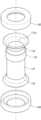
도 2는 도 1에 도시된 일 실시예에 관한 에어로졸 생성 장치의 히터 및 단열부의 사시도이다.
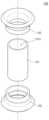
도 3은 도 2에 도시된 일 실시예에 관한 에어로졸 생성 장치의 히터 및 단열부의 분해 사시도이다.
도 4a는 도 2에 도시된 일 실시예에 관한 에어로졸 생성 장치의 히터 및 단열부의 단면도이다.
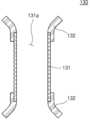
도 4b는 도 3에 도시된 일 실시예에 관한 에어로졸 생성 장치의 히터 및 단열부의 단면도의 부분 확대도이다.
도 5는 다른 실시예에 관한 에어로졸 생성 장치의 히터의 사시도이다.
도 6은 도 5에 도시된 다른 실시예에 관한 에어로졸 생성 장치의 히터의 분해 사시도이다.
도 7은 도 5에 도시된 다른 실시예에 관한 에어로졸 생성 장치의 히터의 단면도이다.
도 8은 또 다른 실시예에 관한 에어로졸 생성 장치의 히터의 사시도이다.
도 9는 도 8에 도시된 또 다른 실시예에 관한 에어로졸 생성 장치의 히터의 단면도이다.
도 10은 에어로졸 생성 물품의 일 예를 개략적으로 도시한 도면이다.
도 11은 에어로졸 생성 물품의 다른 예를 개략적으로 도시한 도면이다.
도 12는 에어로졸 생성 물품의 또 다른 예를 개략적으로 도시한 도면이다.
도 13은 다른 실시예에 따른 에어로졸 생성 장치의 블록도이다.1 is a schematic cross-sectional view of an aerosol generating device according to an embodiment.
FIG. 2 is a perspective view of a heater and an insulator of the aerosol generating device according to the embodiment shown in FIG. 1;
FIG. 3 is an exploded perspective view of a heater and an insulator of the aerosol generating device according to the embodiment shown in FIG. 2 .
FIG. 4A is a cross-sectional view of a heater and an insulator of the aerosol generating device according to the embodiment shown in FIG. 2 .
FIG. 4B is a partially enlarged cross-sectional view of a heater and an insulator of the aerosol generating device according to the embodiment shown in FIG. 3 .
5 is a perspective view of a heater of an aerosol generating device according to another embodiment.
6 is an exploded perspective view of a heater of an aerosol generating device according to another embodiment shown in FIG. 5;
7 is a cross-sectional view of a heater of an aerosol generating device according to another embodiment shown in FIG. 5;
8 is a perspective view of a heater of an aerosol generating device according to another embodiment.
9 is a cross-sectional view of a heater of an aerosol generating device according to another embodiment shown in FIG. 8;
10 schematically illustrates an example of an aerosol-generating article.
11 is a schematic illustration of another example of an aerosol-generating article.
12 schematically depicts another example of an aerosol-generating article.
13 is a block diagram of an aerosol generating device according to another embodiment.
실시예들에서 사용되는 용어는 본 개시에서의 기능을 고려하면서 가능한 현재 널리 사용되는 일반적인 용어들을 선택하였으나, 이는 당 분야에 종사하는 기술자의 의도 또는 판례, 새로운 기술의 출현 등에 따라 달라질 수 있다. 또한 특정한 경우는 출원인이 임의로 선정한 용어도 있으며, 이 경우 해당되는 발명의 설명 부분에서 상세히 그 의미를 기재할 것이다. 따라서 본 개시에서 사용되는 용어는 단순한 용어의 명칭이 아닌, 그 용어가 가지는 의미와 본 개시의 전반에 걸친 내용을 토대로 정의되어야 한다.The terms used in the embodiments have been selected from general terms that are currently widely used as much as possible while considering the functions in the present disclosure, but they may vary depending on the intention or precedent of a person skilled in the art, the emergence of new technologies, and the like. In addition, in certain cases, there are also terms arbitrarily selected by the applicant, and in this case, their meanings will be described in detail in the description of the relevant invention. Therefore, terms used in the present disclosure should be defined based on the meaning of the term and the general content of the present disclosure, not simply the name of the term.
명세서 전체에서 어떤 부분이 어떤 구성요소를 "포함"한다고 할 때, 이는 특별히 반대되는 기재가 없는 한 다른 구성요소를 제외하는 것이 아니라 다른 구성요소를 더 포함할 수 있음을 의미한다. 또한 명세서에 기재된 "-부", "-모듈" 등의 용어는 적어도 하나의 기능이나 동작을 처리하는 단위를 의미하며, 이는 하드웨어 또는 소프트웨어로 구현되거나 하드웨어와 소프트웨어의 결합으로 구현될 수 있다.When it is said that a certain part "includes" a certain component throughout the specification, it means that it may further include other components without excluding other components unless otherwise stated. In addition, terms such as "-unit" and "-module" described in the specification mean a unit that processes at least one function or operation, which may be implemented as hardware or software or a combination of hardware and software.
본 명세서에서 사용된 바와 같이, "적어도 어느 하나의"와 같은 표현이 배열된 구성요소들 앞에 있을 때, 배열된 각각의 구성이 아닌 전체 구성 요소들을 수식한다. 예를 들어, "a, b, 및 c 중 적어도 어느 하나"라는 표현은 a, b, c, 또는 a와 b, a와 c, b와 c, 또는 a와 b와 c를 포함하는 것으로 해석하여야 한다.As used herein, when an expression such as "at least one of" precedes an array of components, it modifies the entire array rather than individual components. For example, the expression "at least one of a, b, and c" should be interpreted as including a, b, c, or a and b, a and c, b and c, or a and b and c. do.
또한 본 명세서에서 사용되는 "제1" 또는 "제2" 등과 같이 서수를 포함하는 용어는 다양한 구성 요소들을 설명하는데 사용할 수 있지만, 구성 요소들은 용어들에 의해 한정되어서는 안된다. 용어들은 하나의 구성 요소를 다른 구성 요소로부터 구별하는 목적으로만 사용된다.In addition, terms including ordinal numbers such as “first” or “second” used in this specification may be used to describe various components, but components should not be limited by the terms. Terms are used only to distinguish one component from another.
명세서 전체에서 "에어로졸 생성 장치"는 사용자의 입을 통해 사용자의 폐로 직접적으로 흡입 가능한 에어로졸을 발생시키기 위해 에어로졸 생성 물질을 이용하여 에어로졸을 생성하는 장치일 수 있다.Throughout the specification, an “aerosol generating device” may be an aerosol generating device using an aerosol generating material to generate an aerosol that can be directly inhaled into the user's lungs through the user's mouth.
명세서 전체에서 "에어로졸 생성 물품"은 흡연을 하는 데 이용되는 물품을 의미한다. 예를 들어, 에어로졸 생성 물품은 점화되어 연소되는 방식으로 이용되는 일반 연소식 궐련일 수 있고, 또는 에어로졸 생성 장치에 의하여 가열되는 방식으로 이용되는 가열식 궐련일 수도 있다. 다른 예시로서, 에어로졸 생성 물품은 카트리지에 함유된 액상이 가열되는 방식으로 이용되는 물품일 수도 있다.Throughout the specification “aerosol generating article” means an article used for smoking. For example, the aerosol-generating article can be a conventional combustible cigarette used in a manner that is ignited and burned, or it can be a heated cigarette used in a manner that is heated by an aerosol-generating device. As another example, an aerosol generating article may be an article used in such a way that a liquid contained in a cartridge is heated.
아래에서는 첨부한 도면을 참고하여 본 개시의 실시예에 대하여 본 개시가 속하는 기술 분야에서 통상의 지식을 가진 자가 용이하게 실시할 수 있도록 상세히 설명한다. 그러나 본 개시는 여러 가지 상이한 형태로 구현될 수 있으며 여기에서 설명하는 실시예에 한정되지 않는다.Hereinafter, with reference to the accompanying drawings, embodiments of the present disclosure will be described in detail so that those skilled in the art can easily carry out the present disclosure. However, the present disclosure may be embodied in many different forms and is not limited to the embodiments described herein.
이하에서는 도면을 참조하여 실시예들을 상세히 설명한다.Hereinafter, embodiments will be described in detail with reference to the drawings.
도 1은 일 실시예에 관한 에어로졸 생성 장치(100)를 개략적으로 도시한 단면도이다.1 is a schematic cross-sectional view of an
도 1을 참조하면, 에어로졸 생성 장치(100)는 제어부(110), 배터리(120), 히터(130), 코일(140), 온도 센서(150) 및 단열부(160)를 포함할 수 있다 도 1에 도시된 에어로졸 생성 장치(100)의 구성 요소, 배치, 형상 등은 예시적인 것이며, 에어로졸 생성 장치(100)에 적용될 수 있는 다양한 실시예들은 본 명세서에 개시된 바에 한정되지 않는다.Referring to FIG. 1 , the
제어부(110)는 에어로졸 생성 장치(100)의 전반적인 동작을 제어할 수 있다. 일 실시예에서, 제어부(110)는 적어도 하나의 프로세서를 포함할 수 있다. 프로세서는 다수의 논리 게이트들의 어레이로 구현될 수도 있고, 범용적인 마이크로 프로세서와 마이크로 프로세서에서 실행될 수 있는 프로그램이 저장된 메모리의 조합으로 구현될 수도 있다. 또한 다른 형태의 하드웨어로 구현될 수도 있음을 본 실시예가 속하는 기술 분야에서 통상의 지식을 가진 자라면 이해할 수 있다.The
제어부(110)는 배터리(120)의 전력을 코일(140)에 공급하는 것을 제어함으로써 히터(130)의 온도를 제어할 수 있다. 예를 들어, 제어부(110)는 배터리(120)와 코일(140) 사이의 스위칭 소자의 스위칭을 제어함으로써 전력 공급을 제어할 수 있다.The
제어부(110)는 온도 센서(150)에 의해 감지된 결과를 분석하고, 이후 수행될 처리들을 제어할 수 있다. 예를 들어, 제어부(110)는 온도 센서(150)에 의해 감지된 결과에 기초하여, 코일(140)의 동작이 개시 또는 종료되도록 코일(140)에 공급되는 전력을 제어할 수 있다. 다른 예를 들어, 제어부(110)는 온도 센서(150)에 의해 감지된 결과에 기초하여, 히터(130)가 소정의 온도까지 가열되거나 적절한 온도를 유지할 수 있도록 코일(140)에 공급되는 전력의 양 및 전력이 공급되는 시간을 제어할 수 있다.The
배터리(120)는 에어로졸 생성 장치(100)가 동작하는 데 이용되는 전력을 공급할 수 있다. 배터리(120)는 히터(130)가 가열될 수 있도록 코일(140)에 전력을 공급할 수 있다. 또한 배터리(120)는 에어로졸 생성 장치(100) 내에 구비된 다른 요소들(예: 온도 센서(150))의 동작에 필요한 전력을 공급할 수 있다. 배터리(120)는 충전이 가능한 배터리이거나 일회용 배터리일 수 있다. 예를 들어, 배터리(120)는 리튬폴리머(LiPoly) 배터리일 수 있으나, 이에 제한되지 않는다.The
히터(130)는 외부에서 인가되는 교번 자기장에 의해 발열함으로써 에어로졸 생성 물품(200)을 가열할 수 있다. 에어로졸 생성 장치(100)는 유도 가열 방식으로 에어로졸 생성 장치(100)에 수용되는 에어로졸 생성 물품(200)을 가열함으로써, 에어로졸을 생성하는 장치일 수 있다.The
구체적으로, 유도 가열 방식은 외부 자기장에 의해 발열하는 자성체에 주기적으로 방향이 변하는 교번 자기장(alternating magnetic field)을 인가하여 자성체를 발열시키는 방식을 의미할 수 있다.Specifically, the induction heating method may refer to a method of generating heat by applying an alternating magnetic field of which direction is periodically changed to a magnetic material generating heat by an external magnetic field.
자성체에 교번 자기장이 인가되는 경우, 자성체에는 와류손(eddy current loss) 및 히스테리시스손(hysteresis loss)에 따른 에너지 손실이 발생할 수 있고, 손실되는 에너지가 열에너지로서 자성체로부터 방출될 수 있다. 자성체에 인가되는 교번 자기장의 진폭 또는 주파수가 클수록 자성체로부터 많은 열에너지가 방출될 수 있다. 자성체에 교번 자기장을 인가함으로써 자성체로부터 열에너지를 방출시킬 수 있고, 자성체로부터 방출되는 열에너지를 에어로졸 생성 물품에 전달할 수 있다.When an alternating magnetic field is applied to the magnetic body, energy loss due to eddy current loss and hysteresis loss may occur in the magnetic body, and the lost energy may be released from the magnetic body as thermal energy. As the amplitude or frequency of the alternating magnetic field applied to the magnetic body increases, more heat energy can be released from the magnetic body. By applying an alternating magnetic field to the magnetic body, thermal energy can be released from the magnetic body, and the thermal energy released from the magnetic body can be transferred to the aerosol-generating article.
히터(130)의 적어도 일부는 강자성체(ferromagnetic substance)로 형성될 수 있다. 예를 들면, 히터(130)는 금속 또는 탄소를 포함할 수 있다. 히터(130)는 페라이트(ferrite), 강자성 합금(ferromagnetic alloy), 스테인리스강(stainless steel) 및 알루미늄(Al) 중 적어도 하나를 포함할 수 있다. 또한 히터(130)는 흑연(graphite), 몰리브덴(molybdenum), 실리콘 카바이드(silicon carbide), 니오븀(niobium), 니켈 합금(nickel alloy), 금속 필름(metal film), 지르코니아(zirconia) 등과 같은 세라믹, 니켈(Ni)이나 코발트(Co) 등과 같은 전이 금속, 붕소(B)나 인(P)과 같은 준금속 중 적어도 하나를 포함할 수도 있다.At least a portion of the
히터(130)는 제1 영역(131)과 제2 영역(132)을 포함할 수 있다. 제1 영역(131)은 에어로졸 생성 물품(200)의 적어도 일부가 수용되는 수용 공간(131a)을 포함할 수 있다. 제1 영역(131)의 형상은 에어로졸 생성 물품(200)을 수용할 수 있는 수용 공간(131a)을 포함할 수 있는 형상이라면 제한 없이 적용될 수 있다. 예를 들어, 제1 영역(131)은 관형 형상일 수 있으며, 내부에 포함되는 수용 공간(131a) 역시 관형 형상일 수 있다.The
다른 예로, 제1 영역(131)의 양 단부는 관형 형상을 가지며, 제1 영역(131)의 중심부는 복수 개의 시트가 서로 이격된 채로 양 단부를 연결하도록 제1 영역(131)의 길이 방향과 평행하게 연장되는 형상을 가질 수 있다. 여기서 제1 영역(131)의 길이 방향이란 제1 영역(131)의 길이가 연장하는 방향을 의미하며, 상대적으로 길이가 긴 방향을 의미할 수 있다.As another example, both ends of the
제1 영역(131)은 수용 공간(131a)에 에어로졸 생성 물품(200)이 수용될 때, 에어로졸 생성 물품(200)과 접촉할 수 있다. 예를 들어, 원통형 에어로졸 생성 물품(200)이 수용 공간(131a)에 수용될 때, 제1 영역(131)은 에어로졸 생성 물품(200)의 외주면을 둘러싸는 형상을 가질 수 있으나, 이에 제한되는 것은 아니다. 다른 예로, 제1 영역(131)은 에어로졸 생성 물품(200)이 수용 공간(131a)에 수용될 때, 제1 영역(131)의 일부가 에어로졸 생성 물품(200)의 적어도 일부를 둘러싸도록 배치되고, 제1 영역(131)의 일부를 제외한 나머지는 에어로졸 생성 물품(200)과 이격되도록 배치되는 형상을 가질 수 있다.The
제1 영역(131)은 수용 공간(131a)의 중심으로부터 멀어지는 방향을 향하여 돌출된 돌출부(133)를 포함할 수 있다. 예를 들어, 제1 영역(131)은 관형 형상을 갖고, 돌출부(133)는 제1 영역(131)의 길이 방향을 따라 연장하는 제1 영역(131)의 일 부분이며, 일 부분을 제외한 나머지 부분보다 두꺼운 두께를 가질 수 있다.The
돌출부(133)는 제1 영역(131)과 일체로 형성될 수 있다. 예를 들어, 제1 영역(131)은 자성체를 포함하는 단일 시트를 이용하여 제조될 수 있으며, 단일 시트 중 두꺼운 두께를 가지는 부분이 돌출부(133)를 형성할 수 있다. 돌출부(133)는 단일 시트의 제1 영역(131)의 일부분을 에칭 공정으로 제거하거나 기계적으로 제거하는 방식으로 형성될 수 있다. 실시예들은 돌출부(133)가 형성되는 방식에 의해 제한되는 것은 아니다. 예를 들어 돌출부(133)는 제1 영역(131)과 별도로 제작되어 제1 영역(131)의 외측에 결합될 수 있다. 돌출부(133)는 용접, 접착제에 의해, 또는 볼트나 리벳과 같은 결합수단에 의해 제1 영역(131)에 결합할 수 있다.The
돌출부(133)가 제1 영역(131)의 돌출부(133)를 제외한 나머지 부분과 상이한 두께를 가짐으로써, 히터(130)에 가변 자기장이 침투될 때, 자기력선들이 불균일하게 집중될 수 있다. 이에 따라 제1 영역(131)의 돌출부(133)가 배치되는 부분은 제1 영역(131)의 돌출부(133)가 배치되지 않는 부분과는 상이한 온도로 가열될 수 있다. 그러므로, 히터(130)가 필요에 따라 수용 공간(131a)에 수용되는 에어로졸 생성 물품(200)을 에어로졸 생성 물품(200)의 각 부위 별로 상이한 온도로 가열하는 것이 가능하다.Since the protruding
제2 영역(132)은 제1 영역(131)의 양단의 적어도 하나에서 적어도 일부가 수용 공간(131a)의 중심으로부터 멀어지는 방향을 향하여 연장될 수 있다. 도 1에는 제2 영역(132)이 제1 영역(131)의 양단에서 배치된 것으로 도시되어 있으나, 제1 영역(131)의 양단 중 수용 공간(131a)으로 에어로졸 생성 물품(200)이 진입하는 부분에만 제2 영역(132)이 배치될 수도 있다.At least a portion of the
도 1에 점선으로 도시된 바와 같이, 에어로졸 생성 물품(200)은 수용 공간(131a)으로 수용 공간(131a)이 연장하는 방향에 대해 경사지게 투입될 수 있다. 여기서 제2 영역(132)은 수용 공간(131a)의 중심으로부터 멀어지는 방향을 향하여 연장됨으로써, 경사지게 투입된 에어로졸 생성 물품(200)이 수용 공간(131a)의 중심으로 원활하게 삽입될 수 있도록 안내할 수 있다.As shown by a dotted line in FIG. 1 , the aerosol-generating
제2 영역(132)은 에어로졸 생성 물품(200)의 원활한 삽입을 안내할 수 있도록, 수용 공간(131a)의 중심으로부터 멀어지는 방향을 향하여 만곡된 형상을 가질 수 있으나, 이에 제한되는 것은 아니다. 예를 들어, 제2 영역(132)은 수용 공간(131a)의 중심으로부터 멀어지는 방향을 향하여 연장된 챔퍼(chamfer) 형상을 가질 수 있다.The
제1 영역(131)과 제2 영역(132)은 일체로 형성될 수 있다. 예를 들어, 제1 영역(131)과 제2 영역(132)은 자성체를 포함하는 단일 시트를 이용하여 제조할 수 있으나, 이에 제한되는 것은 아니다. 제1 영역(131)과 제2 영역(132)은 각각 별도로 제조되어, 분리 가능하게 결합될 수도 있다.The
코일(140)은 히터(130)에 교번 자기장을 인가할 수 있다. 코일(140)에 전력이 공급되는 경우 코일(140)의 내부에 자기장이 형성될 수 있다. 코일(140)에 교류 전류가 인가되는 경우 코일(140)의 내부에 형성되는 자기장의 방향은 지속적으로 변경될 수 있다. 히터(130)가 코일(140)의 내부에 위치하여 주기적으로 방향이 변하는 교번 자기장에 노출되는 경우, 히터(130)가 발열할 수 있고, 히터(130)에 수용되는 에어로졸 생성 물품(200)이 가열될 수 있다.The
코일(140)은 코일(140)에 교번 자기장을 인가하기에 적합한 위치에 배치될 수 있다. 예를 들면, 히터(130)는 에어로졸 생성 물품(200)을 향하는 내측에 배치되고 코일(140)은 히터(130)의 외측에 배치될 수 있다. 이와 같이 코일(140)의 크기 및 배치에 의해 코일(140)의 교번 자기장이 히터(130)에 인가되는 효율이 향상될 수 있다.The
코일(140)에 의해 형성되는 교번 자기장의 진폭 또는 주파수가 변경되는 경우 히터(130)가 에어로졸 생성 물품(200)을 가열하는 정도 또한 변경될 수 있다. 코일(140)에 의한 자기장의 진폭 또는 주파수는 코일(140)에 인가되는 전력에 의해 변경될 수 있으므로, 에어로졸 생성 장치(100)는 코일(140)에 인가되는 전력을 조정함으로써 에어로졸 생성 물품(200)의 가열을 제어할 수 있다. 예를 들면, 에어로졸 생성 장치(100)는 코일(140)에 인가되는 교류 전류의 진폭 및 주파수를 제어할 수 있다.The extent to which
하나의 예시로서, 코일(140)은 솔레노이드(solenoid)로 구현될 수 있다. 코일(140)은 히터(130)의 수용 공간(131a)의 외측면을 따라 권선되는 솔레노이드일 수 있고, 솔레노이드의 내부 공간에 히터(130) 및 에어로졸 생성 물품(200)이 위치할 수 있다. 솔레노이드를 구성하는 도선의 재질은 구리(Cu)일 수 있다. 다만 이에 제한되는 것은 아니고, 은(Ag), 금(Au), 알루미늄(Al), 텅스텐(W), 아연(Zn) 및 니켈(Ni) 중 어느 하나, 또는 적어도 하나를 포함하는 합금이 솔레노이드를 구성하는 도선의 재질이 될 수 있다.As one example, the
온도 센서(150)는 도 1에 도시된 바와 같이, 히터(130)에 맞닿을 수 있다. 히터(130)가 가열되는 온도를 감지할 수 있다. 온도 센서(150)는 제어부(110)에 연결되어 감지한 결과를 제어부(110)에 전달할 수 있다. 온도 센서(150)는 예를 들어, 열전대(thermocouple)일 수 있으나, 이에 제한되는 것은 아니며, 히터(130)의 온도를 감지할 수 있는 장치라면 제한 없이 사용될 수 있다.As shown in FIG. 1 , the
전술한 바와 같이, 제어부(110)는 온도 센서(150)에 의해 감지된 결과에 기초하여 히터(130)가 소정의 온도까지 가열되거나 적절한 온도를 유지할 수 있도록 코일(140)에 공급되는 전력의 양 및 전력이 공급되는 시간을 제어할 수 있다.As described above, the
예를 들어, 온도 센서(150)는 히터(130)의 돌출부(133)에 배치될 수 있다. 온도 센서(150)가 히터(130)의 표면에서 분리되는 것을 방지하기 위하여, 용접 등의 작업을 통해 온도 센서(150)의 일부분이 히터(130)에 결착될 수 있다. 이 경우, 작업 과정에서 히터(130)가 손상되어 히터(130)의 기능에 문제가 발생할 수 있다. 하지만, 온도 센서(150)가 돌출부(133)에 결착될 경우, 비교적 두꺼운 두께를 갖는 돌출부(133)의 우수한 내구성에 의하여 히터(130)의 기능에 영향을 미치지 않을 수 있다.For example, the
단열부(160)는 제2 영역(132)의 적어도 일부와 결합될 수 있다. 단열부(160)는 히터(130)의 열이 외부로 이동하는 것을 차단할 수 있다.The
도 1을 참조하면, 제2 영역(132)은 에어로졸 생성 물품(200)의 삽입을 안내하기 위하여, 에어로졸 생성 장치(100)의 외면에 인접하여 배치될 수 있다. 단열부(160)는 제2 영역(132)의 적어도 일부와 결합됨으로써, 제2 영역(132)으로부터 에어로졸 생성 장치(100)의 외부로 전달되는 열의 양을 효과적으로 감소시킬 수 있다. 이에 따라, 사용자에게 안정적인 에어로졸 생성 장치(100)의 사용 환경을 제공할 수 있다.Referring to FIG. 1 , a
또한 단열부(160)는 제2 영역(132)의 열이 외부로 이동하는 것을 차단함으로써, 열 손실에 의해 코일(140)에서 낭비되는 전력량을 감소시킬 수 있다.In addition, the
이하에서 도 2 내지 도 4b를 참조하여 단열부(160)에 대하여 보다 상세하게 설명한다.Hereinafter, the
도 2는 도 1에 도시된 일 실시예에 관한 에어로졸 생성 장치(100)의 히터(130) 및 단열부(160)의 사시도이다. 도 3은 도 2에 도시된 일 실시예에 관한 에어로졸 생성 장치(100)의 히터(130) 및 단열부(160)의 분해 사시도이다.FIG. 2 is a perspective view of a
도 2 및 도 3을 참조하면, 단열부(160)는 제2 영역(132)의 둘레를 따라 맞물리는 형상을 가질 수 있으나, 이에 제한되는 것은 아니다. 예를 들어, 단열부(160)가 제2 영역(132)의 둘레를 따라 일부에만 배치되고, 일부를 제외한 나머지 부분에는 생략될 수 있다.Referring to FIGS. 2 and 3 , the
에어로졸 생성 물품(200)이 투입되는 부분의 제2 영역(132)과 결합하는 단열부(160)는 에어로졸 생성 물품(200)이 투입될 수 있는 구멍을 포함할 수 있다. 구멍의 크기는 에어로졸 생성 물품(200)의 원활한 투입을 위해, 수용 공간(131a)이 연장하는 방향을 가로지는 방향의 수용 공간(131a)의 단면의 크기와 실질적으로 동일할 수 있다.The
도 2 및 도 3에는 에어로졸 생성 물품(200)의 단부가 수용되는 부분의 제2 영역(132)과 결합하는 단열부(160)도 구멍을 포함하는 것으로 도시되어 있으나, 이에 제한되는 것은 아니다. 에어로졸 생성 물품(200)의 단부가 수용되는 부분의 제2 영역(132)과 결합하는 단열부(160)는 구멍을 포함하지 않을 수 있다.In FIGS. 2 and 3 , the
단열부(160)는 제2 영역(132)에 결합되어 단열 성능을 가지는 소재라면 제한 없이 포함할 수 있다. 예를 들어, 단열부(160)는 고내열성의 고분자 소재를 포함할 수 있다. 예컨대, 단열부(160)는 폴리에테르에테르케톤(PEEK: polyether ether ketone), 폴리페닐설폰(PPSU: polyphenylsulfone), 폴리카보네이트(PC: polycarbonate), 폴리에테르이미드(PEI: polyetherimide), 폴리에테르설폰(PES: polyethersulfone), 아크릴로니트릴-부타디엔-스티렌 수지(ABS: acrylonitrile-butadiene rubber) 등의 고분자 소재를 포함할 수 있다.The
다른 예로, 단열부(160)는 금속 소재를 포함할 수 있다. 예컨대, 스테인리스(SUS: Steel use stainless), 알루미늄(Aluminum) 등의 소재를 포함할 수 있다.As another example, the
도 4a는 도 2에 도시된 일 실시예에 관한 에어로졸 생성 장치(100)의 히터(130) 및 단열부(160)의 단면도이다. 도 4b는 도 3에 도시된 일 실시예에 관한 에어로졸 생성 장치(100)의 히터(130) 및 단열부(160)의 단면도의 부분 확대도이다.FIG. 4A is a cross-sectional view of a
도 4a 및 도 4b를 참조하면, 단열부(160)는 제2 영역(132)의 단부(132e)의 일부(132g)와 접촉하고, 제2 영역(132)의 단부(132e)의 일부(132g)를 제외한 나머지 부분(132f)과 이격되도록 제2 영역(132)에 결합될 수 있다.Referring to FIGS. 4A and 4B , the
일반적인 원통 형상의 히터의 경우, 히터의 단부에 결합되는 단열부가 히터의 단부의 전체 면적에 접촉하므로, 히터와 단열부가 상대적으로 넓은 면적을 접촉하게 된다. 단열부가 히터와 넓은 면적을 접촉함에 따라 단열부가 히터로부터 과량의 열을 전달 받게 되며, 지나치게 높은 온도로 가열될 수 있다. 단열부 자체의 온도가 높아질 경우, 단열부로부터 기대하는 일정 수준 이상의 단열 성능을 달성할 수 없는 문제가 있을 수 있다.In the case of a general cylindrical heater, since the heat insulating part coupled to the end of the heater contacts the entire area of the end of the heater, the heater and the heat insulating part contact a relatively large area. As the heat insulating part contacts the heater over a large area, the heat insulating part receives excessive heat from the heater and may be heated to an excessively high temperature. When the temperature of the heat insulator itself increases, there may be a problem in that the heat insulation performance of a certain level or more expected from the heat insulator cannot be achieved.
또한 고분자 소재를 포함하는 단열부의 경우, 고분자 소재가 단열부의 높은 온도에 의해 용융될 수 있다. 고분자 소재가 용융됨에 따라 단열부의 형상이 변형될 수 있으며, 단열부에 의한 단열 성능이 저하될 수 있다. 게다가, 용융된 고분자 소재는 에어로졸 생성 장치의 내부의 다른 부분으로 침투하여 에어로졸 생성 장치의 고장을 유발할 수도 있다.In addition, in the case of an insulator including a polymeric material, the polymeric material may be melted by the high temperature of the insulator. As the polymer material melts, the shape of the heat insulating part may be deformed, and the heat insulating performance of the heat insulating part may be deteriorated. Additionally, the molten polymeric material may penetrate other parts of the interior of the aerosol-generating device and cause failure of the aerosol-generating device.
일 실시예에 관한 에어로졸 생성 장치(100)의 히터(130)는 수용 공간(131a)의 중심으로부터 멀어지는 방향을 향하여 연장하는 제2 영역(132)을 포함하기 때문에, 히터(130)와 단열부(160)가 접촉하는 면적이 최소화될 수 있다.Since the
구체적으로, 도 4a 및 도 4b에 도시된 바와 같이, 제2 영역(132)이 수용 공간(131a)의 중심으로부터 멀어지는 방향을 향하여 만곡된 경우, 단열부(160)는 제2 영역(132)과의 결합을 유지함과 동시에, 제2 영역(132)의 단부(132e)의 전체 면적과는 이격될 수 있다.Specifically, as shown in FIGS. 4A and 4B , when the
즉, 단열부(160)와 히터(130)가 접촉하는 면적이 상대적으로 감소하므로, 단열부(160)로 전달되는 열의 양이 줄어들 수 있으며, 단열부(160)의 온도가 지나치게 상승하는 것을 방지할 수 있다. 이에 따라, 단열부(160)의 온도가 지나치게 상승하여 발생하는 단열 성능의 저하, 에어로졸 생성 장치(100)의 고장 등의 문제를 해결할 수 있다.That is, since the contact area between the
한편, 제2 영역(132)의 표면의 적어도 일부는 히터(130)의 열을 차단하는 물질을 포함할 수 있다. 히터(130)의 열을 차단하는 물질은 제2 영역(132)의 표면에 증착되거나, 도포될 수 있으나 이에 제한되는 것은 아니다.Meanwhile, at least a portion of the surface of the
제2 영역(132)의 표면이 히터(130)의 열을 차단하는 물질을 포함함에 따라, 제2 영역(132)의 표면의 온도는 비교적 낮게 유지될 수 있으며, 히터(130)의 열이 이동하는 것을 차단하는 단열 성능이 더욱 향상될 수 있다. 에어로졸 생성 장치(100)의 외면에 인접하여 위치하는 제2 영역(132)의 표면의 온도가 낮게 유지될 경우, 사용자의 에어로졸 생성 장치(100)의 사용에 있어서 안정성을 확보할 수도 있다.As the surface of the
히터(130)의 열을 차단하는 물질은 고내열성 고분자 소재, 금속 소재를 포함할 수 있다. 고내열성 고분자 소재와 금속 소재는 전술한 단열부(160)의 소재가 동일하게 사용될 수 있다.A material that blocks heat from the
도 5는 다른 실시예에 관한 에어로졸 생성 장치(100)의 히터(130)의 사시도이다. 도 6은 도 5에 도시된 다른 실시예에 관한 에어로졸 생성 장치(100)의 히터(130)의 분해 사시도이다.5 is a perspective view of a
도 5 및 도 6을 참조할 때, 제2 영역(132)은 제1 영역(131)에 분리 가능하게 결합될 수 있다. 제2 영역(132)과 제1 영역(131)은 각각 별도로 제조된 후 결합될 수 있다. 이에 따라, 제2 영역(132) 및 제1 영역(131)의 제조에 대량 생산 기술이 적용될 수 있으며, 제2 영역(132) 및 제1 영역(131)의 제조의 용이성을 확보할 수 있다.Referring to FIGS. 5 and 6 , the
제2 영역(132)과 제1 영역(131)은 서로 상이한 소재를 포함할 수 있다. 예를 들어, 제2 영역(132)은 고내열성 고분자 소재를 포함할 수 있으며, 제1 영역(131)은 강자성체를 포함할 수 있다. 이 경우, 제2 영역(132)은 에어로졸 생성 물품(200)의 가열에는 참여하지 않는다. 제1 영역(131)이 에어로졸 생성 물품(200)을 가열할 수 있으며, 제2 영역(132)은 제1 영역(131)으로부터 생성되는 열을 차단할 수 있다. 제2 영역(132)이 제1 영역(131)으로부터 생성되는 열을 일차적으로 차단하므로, 히터(130)로부터 에어로졸 생성 장치(100)의 외부로 이동하는 열을 차단하는 단열 성능이 더욱 향상될 수 있다.The
도 7은 도 5에 도시된 다른 실시예에 관한 에어로졸 생성 장치(100)의 히터(130)의 단면도이다.FIG. 7 is a cross-sectional view of the
도 7을 참조하면, 제2 영역(132)은 제1 영역(131)의 단부의 둘레 방향을 따라 연장하여 배치될 수 있다. 즉, 제2 영역(132)이 제1 영역(131)의 단부의 전체와 결합함으로써 수용 공간(131a)의 내부의 열의 적어도 일부가 제1 영역(131)의 단부를 통해 외부로 이동하는 것을 차단할 수 있다.Referring to FIG. 7 , the
또한 제2 영역(132)은 제1 영역(131)의 외측면과 접촉하도록 수용 공간(131a)이 연장하는 방향을 따라 연장될 수 있다. 제2 영역(132)과 제1 영역(131)의 접촉 면적이 증가함에 따라 제2 영역(132)과 제1 영역(131)의 결합력이 향상될 수 있다. 여기서 수용 공간(131a)이 연장하는 방향이란 수용 공간(131a)의 길이가 연장되는 방향을 의미한다.Also, the
도 7에는 제2 영역(132)이 제1 영역(131)의 외측면과 접촉하도록 수용 공간(131a)이 연장하는 방향을 따라 연장되는 것으로 도시되어 있으나, 이에 제한되는 것은 아니다. 제2 영역(132)은 제1 영역(131)의 내측면과 접촉하도록 수용 공간(131a)이 연장하는 방향을 따라 연장될 수도 있으며, 제1 영역(131)의 내측면과 외측면 모두에 접촉하도록 수용 공간(131a)이 연장하는 방향을 따라 연장될 수도 있다.In FIG. 7 , the
도 8은 또 다른 실시예에 관한 에어로졸 생성 장치(100)의 히터(130)의 사시도이다. 도 9는 도 8에 도시된 또 다른 실시예에 관한 에어로졸 생성 장치(100)의 히터(130)의 단면도이다.8 is a perspective view of a
도 8 및 도 9를 참조하면, 제2 영역(132)의 단부를 연결하여 형성되는 면(S)은 수용 공간(131a)이 연장하는 방향(L)을 가로지르는 방향에 대해 경사질 수 있다. 즉, 제2 영역(132)의 단부(132e)의 일 영역은 다른 영역에 비해 수용 공간(131a)이 연장하는 방향을 따라 돌출할 수 있다.Referring to FIGS. 8 and 9 , a surface S formed by connecting the ends of the
에어로졸 생성 장치(100)를 반복적으로 사용하는 동안, 일반적으로 사용자는 습관적으로 에어로졸 생성 장치(100)가 일정한 방향을 향하도록 파지한다. 예를 들어, 사용자는 에어로졸 생성 장치(100)의 외면에 배치되어 에어로졸 생성 장치(100)의 작동을 제어하는 스위치가 사용자의 엄지 손가락에 위치하도록 파지할 수 있다.During repetitive use of the aerosol-generating
사용자가 에어로졸 생성 장치(100)를 일정한 자세로 파지하므로, 사용자가 에어로졸 생성 물품(200)을 수용 공간(131a)으로 투입하는 방향 역시 일정할 수 있다. 이 경우, 제2 영역(132)의 형상을 영역 별로 상이하게 설계함으로써, 에어로졸 생성 물품(200)이 수용 공간(131a)에 보다 원활하게 삽입되도록 할 수 있다.Since the user holds the
즉, 사용자가 반복적으로 에어로졸 생성 물품(200)을 투입할 것으로 예상되는 방향에 대응되는 제2 영역(132)의 단부(132e)의 일 영역을 다른 영역에 비해 수용 공간(131a)이 연장하는 방향(L)을 따라 돌출하도록 설계할 수 있다. 일 예로, 수용 공간(131a)이 연장하는 방향(L)을 따라 돌출하는 제2 영역(132)의 단부(132e)의 일 영역은 나머지 영역에 비해 스위치가 배치되는 에어로졸 생성 장치(100)의 외면에 근접하도록 배치될 수 있으나, 이에 제한되는 것은 아니다.That is, the direction in which the
이에 따라, 도 9에 점선으로 도시된 바와 같이, 제2 영역(132)은 에어로졸 생성 물품(200)이 수용 공간(131a)이 연장하는 방향(L)과 비교적 큰 경사를 갖는 방향으로 투입되더라도, 에어로졸 생성 물품(200)이 무리 없이 수용 공간(131a)의 내부로 안내될 수 있다.Accordingly, as shown by a dotted line in FIG. 9 , the
이하, 도 10 내지 도 12를 참조하여, 에어로졸 생성 물품(200)의 예들을 설명한다.Examples of aerosol-generating
도 10은 에어로졸 생성 물품(200)의 일 예를 개략적으로 도시한 도면들이다.10 schematically depicts an example of an aerosol-generating
도 10을 참조하면, 에어로졸 생성 물품(200)은 담배 로드(210) 및 필터 로드(220)를 포함한다. 도 1을 참조하여 상술한 제1 섹션은 담배 로드(210)를 포함하고, 제2 섹션은 필터 로드(220)를 포함한다.Referring to FIG. 10 , an aerosol-generating
도 10에는 필터 로드(220)가 단일 세그먼트로 도시되어 있으나, 이에 한정되지 않는다. 다시 말해, 필터 로드(220)는 복수의 세그먼트들로 구성될 수도 있다. 예를 들어, 필터 로드(220)는 에어로졸을 냉각하는 제1 세그먼트 및 에어로졸 내에 포함된 소정의 성분을 필터링하는 제2 세그먼트를 포함할 수 있다. 또한 필요에 따라, 필터 로드(220)에는 다른 기능을 수행하는 적어도 하나의 세그먼트를 더 포함할 수 있다.Although
에어로졸 생성 물품(200)은 적어도 하나의 래퍼(240)에 의하여 포장될 수 있다. 래퍼(240)에는 외부 공기가 유입되거나 내부 기체가 유출되는 적어도 하나의 구멍(hole)이 형성될 수 있다. 일 예로서, 에어로졸 생성 물품(200)은 하나의 래퍼(240)에 의하여 포장될 수 있다. 다른 예로서, 에어로졸 생성 물품(200)은 2 이상의 래퍼(240)들에 의하여 중첩적으로 포장될 수도 있다. 예를 들어, 제1 래퍼(241)에 의하여 담배 로드(210)가 포장되고, 래퍼들(242, 243, 244)에 의하여 필터 로드(220)가 포장될 수 있다. 그리고, 단일 래퍼(245)에 의하여 에어로졸 생성 물품(200) 전체가 재포장될 수 있다. 만약, 필터 로드(220)가 복수의 세그먼트들로 구성되어 있다면, 각각의 세그먼트가 래퍼들(242, 243, 244)에 의하여 포장될 수 있다.The aerosol-generating
담배 로드(210)는 에어로졸 생성 물질을 포함한다. 예를 들어, 에어로졸 생성 물질은 글리세린, 프로필렌 글리콜, 에틸렌 글리콜, 디프로필렌 글리콜, 디에틸렌 글리콜, 트리에틸렌 글리콜, 테트라에틸렌 글리콜, 및 올레일 알코올 중 적어도 하나를 포함할 수 있으나, 이에 한정되지 않는다. 또한 담배 로드(210)는 풍미제, 습윤제, 및/또는 유기산(organic acid)과 같은 다른 첨가 물질을 함유할 수 있다. 또한 담배 로드(210)에는, 멘솔 또는 보습제 등의 가향액이, 담배 로드(210)에 분사됨으로써 첨가할 수 있다.
담배 로드(210)는 다양하게 제작될 수 있다. 예를 들어, 담배 로드(210)는 시트(sheet)로 제작될 수도 있고, 가닥(strand)으로 제작될 수도 있다. 또한 담배 로드(210)는 담배 시트가 잘게 잘린 각초로 제작될 수도 있다. 또한 담배 로드(210)는 열 전도 물질에 의하여 둘러싸일 수 있다. 예를 들어, 열 전도 물질은 알루미늄 호일과 같은 금속 호일일 수 있으나, 이에 한정되지 않는다. 일 예로, 담배 로드(210)를 둘러싸는 열 전도 물질은 담배 로드(210)에 전달되는 열을 고르게 분산시켜 담배 로드에 가해지는 열 전도율을 향상시킬 수 있으며, 이로 인해 담배 맛을 향상시킬 수 있다. 또한 담배 로드(210)를 둘러싸는 열 전도 물질은 유도 가열식 히터에 의해 가열되는 서셉터로서의 기능을 할 수 있다. 이때, 도면에 도시되지는 않았으나, 담배 로드(210)는 외부를 둘러싸는 열 전도 물질 이외에도 추가의 서셉터를 더 포함할 수 있다.
필터 로드(220)는 셀룰로오스 아세테이트 필터일 수 있다. 한편, 필터 로드(220)의 형상에는 제한이 없다. 예를 들어, 필터 로드(220)는 원기둥 형(type) 로드일 수도 있고, 내부에 중공을 포함하는 튜브 형(type) 로드일 수도 있다. 또한 필터 로드(220)는 리세스 형(type) 로드일 수도 있다. 만약, 필터 로드(220)가 복수의 세그먼트들로 구성된 경우, 복수의 세그먼트들 중 적어도 하나가 다른 형상으로 제작될 수도 있다.The
필터 로드(220)는 향미가 발생되도록 제작될 수도 있다. 일 예로서, 필터 로드(220)에 가향액이 분사될 수도 있고, 가향액이 도포된 별도의 섬유가 필터 로드(220)의 내부에 삽입될 수도 있다.The
또한 필터 로드(220)에는 적어도 하나의 캡슐(230)이 포함될 수 있다. 여기에서, 캡슐(230)은 향미 또는 에어로졸을 발생시킬 수 있다. 예를 들어, 캡슐(230)은 향료를 포함하는 액체를 피막으로 감싼 구조일 수 있다. 캡슐(230)은 구형 또는 원통형의 형상을 가질 수 있으나, 이에 제한되지 않는다.In addition, at least one
만약, 필터 로드(220)에 에어로졸을 냉각하는 세그먼트가 포함될 경우, 냉각 세그먼트는 고분자 물질 또는 생분해성 고분자 물질로 제조될 수 있다. 예를 들어, 냉각 세그먼트는 순수한 폴리락트산만으로 제작될 수 있으나, 이에 한정되지 않는다. 또는, 냉각 세그먼트는 복수의 구멍들이 뚫린 셀룰로오스 아세테이트 필터로 제작될 수 있다. 그러나, 냉각 세그먼트는 상술한 예에 한정되지 않고, 에어로졸이 냉각되는 기능을 수행할 수 있다면, 제한 없이 해당될 수 있다.If the
도 11은 에어로졸 생성 물품(200)의 다른 예를 개략적으로 도시한 도면이다.11 is a schematic illustration of another example of an aerosol-generating
도 11을 참조하면, 에어로졸 생성 물품(200)은 전단 플러그(250)를 더 포함할 수 있다. 전단 플러그(250)는 담배 로드(210)에 있어서, 필터 로드(220)에 반대되는 일 측에 위치할 수 있다. 전단 플러그(250)는 담배 로드(210)가 외부로 이탈하는 것을 방지할 수 있으며, 흡연 중에 담배 로드(210)로부터 액상화된 에어로졸이 에어로졸 생성 장치로 흘러 들어가는 것을 방지할 수 있다.Referring to FIG. 11 , the aerosol-generating
필터 로드(220)은 제1 세그먼트(221) 및 제2 세그먼트(222)를 포함할 수 있다. 여기에서, 제1 세그먼트(221)는 도 10의 필터 로드(220)의 제1 세그먼트에 대응될 수 있고, 제2 세그먼트(222)는 도 10의 필터 로드(220)의 제2 세그먼트에 대응될 수 있다.The
에어로졸 생성 물품(200)의 직경 및 전체 길이는 도 10의 에어로졸 생성 물품(200)의 직경 및 전체 길이에 대응될 수 있다. 예를 들어, 전단 플러그(250)의 길이는 약 7mm, 담배 로드(210)의 길이는 약 15mm, 제1 세그먼트(221)의 길이는 약 12mm, 제2 세그먼트(222)의 길이는 약 14mm일 수 있으나, 이에 한정되지 않는다.The diameter and overall length of the aerosol-generating
에어로졸 생성 물품(200)은 적어도 하나의 래퍼(240)에 의하여 포장될 수 있다. 래퍼(240)에는 외부 공기가 유입되거나 내부 기체가 유출되는 적어도 하나의 구멍(hole)이 형성될 수 있다. 예를 들어, 제1 래퍼(241)에 의하여 전단 플러그(250)가 포장되고, 제2 래퍼(242)에 의하여 담배 로드(210)가 포장되고, 제3 래퍼(243)에 의하여 제1 세그먼트(221)가 포장되고, 제4 래퍼(244)에 의하여 제2 세그먼트(222)가 포장될 수 있다. 그리고, 제5 래퍼(245)에 의하여 에어로졸 생성 물품(200) 전체가 재포장될 수 있다.The aerosol-generating
또한 제5 래퍼(245)에는 적어도 하나의 천공(246)이 형성될 수 있다. 예를 들어, 천공(246)은 담배 로드(210)를 둘러싸는 영역에 형성될 수 있으나, 이에 제한되지 않는다. 천공(246)은 히터에 의하여 형성된 열을 담배 로드(210)의 내부로 전달하는 역할을 수행할 수 있다.In addition, at least one
또한 제2 세그먼트(222)에는 적어도 하나의 캡슐(230)이 포함될 수 있다. 여기에서, 캡슐(230)은 향미 또는 에어로졸을 발생시킬 수 있다. 예를 들어, 캡슐(230)은 향료를 포함하는 액체를 피막으로 감싼 구조일 수 있다. 캡슐(230)은 구형 또는 원통형의 형상을 가질 수 있으나, 이에 제한되지 않는다.Also, at least one
도 12는 에어로졸 생성 물품(200)의 또 다른 예를 개략적으로 도시한 도면이다.12 schematically depicts another example of an aerosol-generating
도 12를 참조하면, 에어로졸 생성 물품(200)은 제1 부분(260), 제2 부분(270), 제3 부분(280), 및 제4 부분(290)을 포함할 수 있다. 구체적으로, 제1 부분(260), 제2 부분(270), 제3 부분(280), 및 제4 부분(290)은 각각 에어로졸 생성 요소, 담배 요소, 냉각 요소, 및 필터 요소를 포함할 수 있다. 일 예로서, 제1 부분(260)은 에어로졸 생성 물질을 포함할 수 있고, 제2 부분(270)은 담배 물질 및 보습제를 포함할 수 있으며, 제3 부분(280)은 제1 부분(260) 및 제2 부분(270)을 통과하는 기류를 냉각시킬 수 있고, 제4 부분(290)은 필터 물질을 포함할 수 있다.Referring to FIG. 12 , the aerosol-generating
도 12를 참조하면, 제1 부분(260), 제2 부분(270), 제3 부분(280), 및 제4 부분(290)은, 에어로졸 생성 물품(200)의 길이 방향을 기준으로 순서대로 정렬될 수 있다. 여기에서, 에어로졸 생성 물품(200)의 길이 방향은 에어로졸 생성 물품(200)의 길이가 연장되는 방향일 수 있다. 예를 들어, 에어로졸 생성 물품(200)의 길이 방향은, 제1 부분(260)에서 제4 부분(290)을 향하는 방향일 수 있다. 이에 따라, 제1 부분(260) 및 제2 부분(270) 중 적어도 하나에서 발생되는 에어로졸이 제1 부분(260), 제2 부분(270), 제3 부분(280), 및 제4 부분(290)을 순서대로 통과하며 기류를 형성할 수 있고, 이에 따라 흡연자는 제4 부분(290)으로부터 에어로졸을 흡입할 수 있다.Referring to FIG. 12 , a
제1 부분(260)은 에어로졸 생성 요소를 포함할 수 있다. 또한 풍미제, 습윤제 및/또는 유기산(organic acid)과 같은 다른 첨가 물질을 함유할 수 있으며, 멘솔 또는 보습제 등의 가향액을 함유할 수 있다. 여기에서, 에어로졸 생성 요소는, 예를 들어, 글리세린, 프로필렌 글리콜, 에틸렌 글리콜, 디프로필렌 글리콜, 디에틸렌 글리콜, 트리에틸렌 글리콜, 테트라에틸렌 글리콜 및 올레일 알코올 중 적어도 하나를 포함할 수 있다.The
제1 부분(260)은 권축된 시트를 포함할 수 있으며, 에어로졸 생성 요소는 권축된 시트에 함침된 상태로 제1 부분(260)에 포함될 수 있다. 또한 풍미제, 습윤제 및/또는 유기산(organic acid)와 같은 다른 첨가 물질들 및 가향액은 권축된 시트에 흡수된 상태로 제1 부분(260)에 포함될 수 있다.The
권축된 시트는 고분자 소재로 구성된 시트일 수 있다. 예를 들어, 고분자 소재는 종이, 셀룰로오스 아세테이트(cellulose acetate), 라이오셀(lyocell), 폴리락트산(polylactic acid) 중 적어도 하나를 포함할 수 있다. 예를 들어, 권축된 시트는 고온으로 가열되더라도 열에 의한 이취가 발생되지 않는 종이 시트일 수 있다. 다만, 이에 제한되는 것은 아니다.The crimped sheet may be a sheet made of a polymer material. For example, the polymer material may include at least one of paper, cellulose acetate, lyocell, and polylactic acid. For example, the crimped sheet may be a paper sheet that does not generate off-flavors due to heat even when heated to a high temperature. However, it is not limited thereto.
제1 부분(260)은 에어로졸 생성 물품(200)의 말단부터 약 7 내지 약 20 mm 지점까지 연장될 수 있고, 제2 부분(270)은 제1 부분(260)이 끝나는 지점부터 약 7 내지 약 20 mm 지점까지 연장될 수 있다. 다만, 이러한 수치범위에 반드시 제한되는 것은 아니며, 제1 부분(260) 및 제2 부분(270) 각각이 연장되는 길이는 통상의 기술자가 용이하게 변경할 수 있는 범위에서 적절하게 조절될 수 있다.The
제2 부분(270)은 담배 요소를 포함할 수 있다. 담배 요소는 특정 형태의 담배 물질일 수 있다. 예를 들어, 담배 요소는 담배 각초, 담배 입자(particle), 담배 시트(sheet), 담배 비즈(beads), 담배 과립(granule), 담배 분말(powder) 또는 담배 추출물의 형태를 가질 수 있다. 또한 담배 물질은, 예를 들어, 담배잎, 담배 옆맥, 팽화 담배, 절단된 각초, 판상엽 각초, 및 재구성 담배 중 1종 이상을 포함할 수 있다.The
제3 부분(280)은, 제1 부분(260) 및 제2 부분(270)을 통과하는 기류를 냉각시킬 수 있다. 제3 부분(280)은 고분자 물질 또는 생분해성 고분자 물질로 제조될 수 있으며, 냉각 기능을 가질 수 있다. 예를 들어, 제3 부분(280)은 폴리락트산(PLA) 섬유로 제작될 수 있으나, 이에 한정되지 않는다. 또는, 제3 부분(280)은 복수의 구멍들이 뚫린 셀룰로오스 아세테이트 필터로 제작될 수 있다. 그러나, 제3 부분(280)은 상술한 예시에 한정되지 않고, 에어로졸이 냉각되는 기능을 수행하는 물질은, 제한 없이 이에 해당될 수 있다. 예를 들어, 제3 부분(280)은 중공을 포함하는 튜브 필터 또는 지관 필터일 수 있다.The
제4 부분(290)은, 필터 물질을 포함할 수 있다. 예를 들어, 제4 부분(290)은 셀룰로오스 아세테이트 필터일 수 있다. 한편, 제4 부분(290)의 형상에는 제한이 없다. 예를 들어, 제4 부분(290)은 원기둥 형(type) 로드일 수도 있고, 내부에 중공을 포함하는 튜브 형(type) 로드일 수도 있다. 또한 제4 부분(290)은 리세스 형(type) 로드일 수도 있다. 만약, 제4 부분(290)이 복수의 세그먼트들로 구성된 경우, 복수의 세그먼트들 중 적어도 하나가 다른 형상으로 제작될 수도 있다.The
제4 부분(290)은 향미가 발생되도록 제작될 수도 있다. 일 예로서, 제4 부분(290)에 가향액이 분사될 수도 있고, 가향액이 도포된 별도의 섬유가 제4 부분(290)의 내부에 삽입될 수도 있다.The
에어로졸 생성 물품(200)은 제1 부분(260) 내지 제4 부분(290) 중 적어도 일부를 둘러싸는 래퍼(240)를 포함할 수 있다. 또한 에어로졸 생성 물품(200)은 제1 부분(260) 내지 제4 부분(290) 전부를 둘러싸는 래퍼(240)를 포함할 수 있다. 래퍼(240)는 에어로졸 생성 물품(200)의 최외곽에 위치될 수 있으며, 래퍼(240)는 단일 래퍼일 수 있으나, 복수 개의 래퍼들의 조합일 수 있다.The aerosol-generating
일 예로서, 에어로졸 생성 물품(200)의 제1 부분(260)은 에어로졸 생성 물질을 함유하는 권축된 주름진 시트를 포함하고, 제2 부분(270)은 담배 물질로서 판상엽 각초 및 보습제로서 글리세린을 포함할 수 있으며, 제3 부분(280)은 지관을 포함하고, 제4 부분(290)은 셀룰로오스 아세테이트 섬유를 포함할 수 있으나, 이에 반드시 제한되는 것은 아니다.As an example, the
도 13은 다른 실시예에 따른 에어로졸 생성 장치(100)의 블록도이다.13 is a block diagram of an
에어로졸 생성 장치(100)는 제어부(110), 센싱부(20), 출력부(30), 배터리(120), 히터(130), 사용자 입력부(60), 메모리(70) 및 통신부(80)를 포함할 수 있다. 다만, 에어로졸 생성 장치(100)의 내부 구조는 도 13에 도시된 것에 제한되지 않는다. 즉, 에어로졸 생성 장치(100)의 설계에 따라, 도 13에 도시된 구성 중 일부가 생략되거나 새로운 구성이 더 추가될 수 있음을 본 실시예와 관련된 기술 분야에서 통상의 지식을 가진 자라면 이해할 수 있다.The
센싱부(20)는 에어로졸 생성 장치(100)의 상태 또는 에어로졸 생성 장치(100) 주변의 상태를 감지하고, 감지된 정보를 제어부(110)에 전달할 수 있다. 제어부(110)는 상기 감지된 정보에 기초하여, 히터(130)의 동작 제어, 흡연의 제한, 에어로졸 생성 물품(예: 궐련, 카트리지 등)의 삽입 여부 판단, 알림 표시 등과 같은 다양한 기능들이 수행되도록 에어로졸 생성 장치(100)를 제어할 수 있다.The
센싱부(20)는 온도 센서(150), 삽입 감지 센서(24) 및 퍼프 센서(26) 중 적어도 하나를 포함할 수 있으나, 이에 제한되지 않는다.The
온도 센서(150)는 히터(130)(또는, 에어로졸 생성 물질)가 가열되는 온도를 감지할 수 있다. 에어로졸 생성 장치(100)는 히터(130)의 온도를 감지하는 별도의 온도 센서를 포함하거나, 히터(130) 자체가 온도 센서의 역할을 수행할 수 있다. 또는, 온도 센서(150)는 배터리(120)의 온도를 모니터링하도록 배터리(120)의 주위에 배치된 것일 수도 있다.The
삽입 감지 센서(24)는 에어로졸 생성 물품의 삽입 및/또는 제거를 감지할 수 있다. 예를 들어, 삽입 감지 센서(24)는 필름 센서, 압력 센서, 광 센서, 저항성 센서, 용량성 센서, 유도성 센서 및 적외선 센서 중 적어도 하나를 포함할 수 있고, 에어로졸 생성 물품이 삽입 및/또는 제거됨에 따른 신호 변화를 감지할 수 있다.
퍼프 센서(26)는 기류 통로 또는 기류 채널의 다양한 물리적 변화에 기초하여 사용자의 퍼프를 감지할 수 있다. 예를 들어, 퍼프 센서(26)는 온도 변화, 유량(flow) 변화, 전압 변화 및 압력 변화 중 어느 하나에 기초하여 사용자의 퍼프를 감지할 수 있다.The
센싱부(20)는 전술한 센서 외에, 온/습도 센서, 기압 센서, 지자기 센서(magnetic sensor), 가속도 센서(acceleration sensor), 자이로스코프 센서, 위치 센서(예컨대, GPS), 근접 센서, 및 RGB 센서(illuminance sensor) 중 적어도 하나를 더 포함할 수 있다. 각 센서들의 기능은 그 명칭으로부터 통상의 기술자가 직관적으로 추론할 수 있으므로, 구체적인 설명은 생략될 수 있다.In addition to the sensors described above, the
출력부(30)는 에어로졸 생성 장치(100)의 상태에 대한 정보를 출력하여 사용자에게 제공할 수 있다. 출력부(30)는 디스플레이부(32), 햅틱부(34) 및 음향 출력부(36) 중 적어도 하나를 포함할 수 있으나, 이에 제한되는 것은 아니다. 디스플레이부(32)와 터치 패드가 레이어 구조를 이루어 터치 스크린으로 구성되는 경우, 디스플레이부(32)는 출력 장치 이외에 입력 장치로도 사용될 수 있다.The
디스플레이부(32)는 에어로졸 생성 장치(100)에 대한 정보를 사용자에게 시각적으로 제공할 수 있다. 예를 들어, 에어로졸 생성 장치(100)에 대한 정보는 에어로졸 생성 장치(100)의 배터리(120)의 충/방전 상태, 히터(130)의 예열 상태, 에어로졸 생성 물품의 삽입/제거 상태 또는 에어로졸 생성 장치(100)의 사용이 제한되는 상태(예: 이상 물품 감지) 등의 다양한 정보를 의미할 수 있고, 디스플레이부(32)는 상기 정보를 외부로 출력할 수 있다. 디스플레이부(32)는 예를 들면, 액정 디스플레이 패널(LCD), 유기 발광 디스플레이 패널(OLED) 등일 수 있다. 또한, 디스플레이부(32)는 LED 발광 소자 형태일 수도 있다.The
햅틱부(34)는 전기적 신호를 기계적인 자극 또는 전기적인 자극으로 변환하여 에어로졸 생성 장치(100)에 대한 정보를 사용자에게 촉각적으로 제공할 수 있다. 예를 들어, 햅틱부(34)는 모터, 압전 소자, 또는 전기 자극 장치를 포함할 수 있다.The
음향 출력부(36)는 에어로졸 생성 장치(100)에 대한 정보를 사용자에게 청각적으로 제공할 수 있다. 예를 들어, 음향 출력부(36)는 전기 신호를 음향 신호로 변환하여 외부로 출력할 수 있다.The
배터리(120)는 에어로졸 생성 장치(100)가 동작하는데 이용되는 전력을 공급할 수 있다. 배터리(120)는 히터(130)가 가열될 수 있도록 전력을 공급할 수 있다. 또한, 배터리(120)는 에어로졸 생성 장치(100) 내에 구비된 다른 구성들(예: 센싱부(20), 출력부(30), 사용자 입력부(60), 메모리(70) 및 통신부(80))의 동작에 필요한 전력을 공급할 수 있다. 배터리(120)는 충전이 가능한 배터리이거나 일회용 배터리일 수 있다. 예를 들어, 배터리(120)는 리튬폴리머(LiPoly) 배터리일 수 있으나, 이에 제한되지 않는다.The
히터(130)는 배터리(120)로부터 전력을 공급받아 에어로졸 생성 물질을 가열할 수 있다. 도 13에 도시되지는 않았으나, 에어로졸 생성 장치(100)는 배터리(120)의 전력을 변환하여 히터(130)에 공급하는 전력 변환 회로(예: DC/DC 컨버터)를 더 포함할 수 있다. 또한, 에어로졸 생성 장치(100)가 유도 가열 방식으로 에어로졸을 생성하는 경우, 에어로졸 생성 장치(100)는 배터리(120)의 직류 전원을 교류 전원으로 변환하는 DC/AC 컨버터를 더 포함할 수 있다.The
제어부(110), 센싱부(20), 출력부(30), 사용자 입력부(60), 메모리(70) 및 통신부(10)는 배터리(120)로부터 전력을 공급받아 기능을 수행할 수 있다. 도 13에 도시되지는 않았으나, 배터리(120)의 전력을 변환하여 각각의 구성요소들에 공급하는 전력 변환 회로, 예를 들면 LDO(low dropout) 회로 또는 전압 레귤레이터 회로를 더 포함할 수 있다.The
일 실시예에서, 히터(130)는 임의의 적합한 전기 저항성 물질로 형성될 수 있다. 예를 들어, 적합한 전기 저항성 물질은 타이타늄, 지르코늄, 탄탈럼, 백금, 니켈, 코발트, 크로뮴, 하프늄, 나이오븀, 몰리브데넘, 텅스텐, 주석, 갈륨, 망간, 철, 구리, 스테인리스강, 니크롬 등을 포함하는 금속 또는 금속 합금일 수 있으나, 이에 제한되지 않는다. 또한, 히터(130)는 금속 열선(wire), 전기 전도성 트랙(track)이 배치된 금속 열판(plate), 세라믹 발열체 등으로 구현될 수 있으나, 이에 제한되지 않는다.In one embodiment,
다른 실시예에서, 히터(130)는 유도 가열 방식의 히터일 수 있다. 예를 들어, 히터(130)는 코일에 의해 인가된 자기장을 통해 발열하여, 에어로졸 생성 물질을 가열하는 서셉터를 포함할 수 있다.In another embodiment, the
사용자 입력부(60)는 사용자로부터 입력된 정보를 수신하거나, 사용자에게 정보를 출력할 수 있다. 예를 들어, 사용자 입력부(60)는 키 패드(key pad), 돔 스위치 (dome switch), 터치 패드(접촉식 정전 용량 방식, 압력식 저항막 방식, 적외선 감지 방식, 표면 초음파 전도 방식, 적분식 장력 측정 방식, 피에조 효과 방식 등), 조그 휠, 조그 스위치 등이 있을 수 있으나 이에 제한되는 것은 아니다. 또한, 도 13에 도시되지는 않았으나, 에어로졸 생성 장치(100)는 USB(universal serial bus) 인터페이스 등과 같은 연결 인터페이스(connection interface)를 더 포함하고, USB 인터페이스 등과 같은 연결 인터페이스를 통해 다른 외부 장치와 연결하여 정보를 송수신하거나, 배터리(120)를 충전할 수 있다.The
메모리(70)는 에어로졸 생성 장치(100) 내에서 처리되는 각종 데이터들을 저장하는 하드웨어로서, 제어부(110)에서 처리된 데이터들 및 처리될 데이터들을 저장할 수 있다. 메모리(70)는 플래시 메모리 타입(flash memory type), 하드디스크 타입(hard disk type), 멀티미디어 카드 마이크로 타입(multimedia card micro type), 카드 타입의 메모리(예를 들어 SD 또는 XD 메모리 등), 램(RAM, random access memory) SRAM(static random access memory), 롬(ROM, read-only memory), EEPROM(electrically erasable programmable read-only memory), PROM(programmable read-only memory), 자기 메모리, 자기 디스크, 광디스크 중 적어도 하나의 타입의 저장매체를 포함할 수 있다. 메모리(70)는 에어로졸 생성 장치(100)의 동작 시간, 최대 퍼프 횟수, 현재 퍼프 횟수, 적어도 하나의 온도 프로 파일 및 사용자의 흡연 패턴에 대한 데이터 등을 저장할 수 있다.The
통신부(80)는 다른 전자 장치와의 통신을 위한 적어도 하나의 구성 요소를 포함할 수 있다. 예를 들어, 통신부(80)는 근거리 통신부(82) 및 무선 통신부(84)를 포함할 수 있다.The
근거리 통신부(short-range wireless communication unit)(82)는 블루투스 통신부, BLE(Bluetooth Low Energy) 통신부, 근거리 무선 통신부(Near Field Communication unit), WLAN(와이파이) 통신부, 지그비(Zigbee) 통신부, 적외선(IrDA, infrared Data Association) 통신부, WFD(Wi-Fi Direct) 통신부, UWB(ultra wideband) 통신부, Ant+ 통신부 등을 포함할 수 있으나, 이에 제한되지 않는다.The short-range
무선 통신부(84)는 셀룰러 네트워크 통신부, 인터넷 통신부, 컴퓨터 네트워크(예: LAN 또는 WAN) 통신부 등을 포함할 수 있으나, 이에 제한되지 않는다. 무선 통신부(84)는 가입자 정보(예: 국제 모바일 가입자 식별자(IMSI)를 이용하여 통신 네트워크 내에서 에어로졸 생성 장치(100)를 확인 및 인증할 수도 있다.The
제어부(110)는 에어로졸 생성 장치(100)의 전반적인 동작을 제어할 수 있다. 일 실시예에서, 제어부(110)는 적어도 하나의 프로세서를 포함할 수 있다. 프로세서는 다수의 논리 게이트들의 어레이로 구현될 수도 있고, 범용적인 마이크로 프로세서와 이 마이크로 프로세서에서 실행될 수 있는 프로그램이 저장된 메모리의 조합으로 구현될 수도 있다. 또한, 다른 형태의 하드웨어로 구현될 수도 있음을 본 실시예가 속하는 기술 분야에서 통상의 지식을 가진 자라면 이해할 수 있다.The
제어부(110)는 배터리(120)의 전력을 히터(130)에 공급하는 것을 제어함으로써 히터(130)의 온도를 제어할 수 있다. 예를 들어, 제어부(110)는 배터리(120)와 히터(130) 사이의 스위칭 소자의 스위칭을 제어함으로써 전력 공급을 제어할 수 있다. 다른 예에서, 제어부(110)의 제어 명령에 따라 가열직접회로가 히터(130)에 대한 전력 공급을 제어할 수도 있다.The
제어부(110)는 센싱부(20)에 의해 감지된 결과를 분석하고, 이후 수행될 처리들을 제어할 수 있다. 예를 들어, 제어부(110)는 센싱부(20)에 의해 감지된 결과에 기초하여, 히터(130)의 동작이 개시 또는 종료되도록 히터(130)에 공급되는 전력을 제어할 수 있다. 다른 예를 들어, 제어부(110)는 센싱부(20)에 의해 감지된 결과에 기초하여, 히터(130)가 소정의 온도까지 가열되거나 적절한 온도를 유지할 수 있도록 히터(130)에 공급되는 전력의 양 및 전력이 공급되는 시간을 제어할 수 있다.The
제어부(110)는 센싱부(20)에 의해 감지된 결과에 기초하여, 출력부(30)를 제어할 수 있다. 예를 들어, 퍼프 센서(26)를 통해 카운트 된 퍼프 횟수가 기 설정된 횟수에 도달하면, 제어부(110)는 디스플레이부(32), 햅틱부(34) 및 음향 출력부(36) 중 적어도 하나를 통해 사용자에게 에어로졸 생성 장치(100)가 곧 종료될 것을 예고할 수 있다.The
일 실시예는 컴퓨터에 의해 실행되는 프로그램 모듈과 같은 컴퓨터에 의해 실행가능한 명령어를 포함하는 기록 매체의 형태로도 구현될 수 있다. 컴퓨터 판독 가능 매체는 컴퓨터에 의해 액세스될 수 있는 임의의 가용 매체일 수 있고, 휘발성 및 비휘발성 매체, 분리형 및 비분리형 매체를 모두 포함한다. 또한 컴퓨터 판독가능 매체는 컴퓨터 저장 매체 및 통신 매체를 모두 포함할 수 있다. 컴퓨터 저장 매체는 컴퓨터 판독가능 명령어, 데이터 구조, 프로그램 모듈, 또는 기타 데이터와 같은 정보의 저장을 위한 임의의 방법 또는 기술로 구현된 휘발성 및 비휘발성, 분리형 및 비분리형 매체를 모두 포함한다. 통신 매체는 전형적으로 컴퓨터 판독가능 명령어, 데이터 구조, 프로그램 모듈과 같은 변조된 데이터 신호의 기타 데이터, 또는 기타 전송 메커니즘을 포함하며, 임의의 정보 전달 매체를 포함한다.An embodiment may be implemented in the form of a recording medium including instructions executable by a computer, such as program modules executed by a computer. Computer readable media can be any available media that can be accessed by a computer and includes both volatile and nonvolatile media, removable and non-removable media. Also, computer readable media may include both computer storage media and communication media. Computer storage media includes both volatile and nonvolatile, removable and non-removable media implemented in any method or technology for storage of information such as computer readable instructions, data structures, program modules, or other data. Communication media typically includes computer readable instructions, data structures, other data in a modulated data signal such as program modules, or other transport mechanism, and includes any information delivery media.
본 실시예와 관련된 기술 분야에서 통상의 지식을 가진 자는 상기된 기재의 본질적인 특성에서 벗어나지 않는 범위에서 변형된 형태로 구현될 수 있음을 이해할 수 있을 것이다. 그러므로 개시된 방법들은 한정적인 관점이 아니라 설명적인 관점에서 고려되어야 한다. 발명의 범위는 전술한 설명이 아니라 청구범위에 나타나 있으며, 그와 동등한 범위 내에 있는 모든 차이점은 발명에 포함된 것으로 해석되어야 할 것이다.Those skilled in the art related to the present embodiment will be able to understand that it may be implemented in a modified form within a range that does not deviate from the essential characteristics of the above description. Therefore, the disclosed methods are to be considered in an illustrative rather than a limiting sense. The scope of the invention is shown in the claims rather than the foregoing description, and all differences within the equivalent scope should be construed as being included in the invention.
100: 에어로졸 생성 장치110: 제어부
120: 배터리
130: 히터131: 제1 영역
131a: 수용 공간132: 제2 영역
133: 돌출부
140: 코일150: 온도 센서
160: 단열부
200: 에어로졸 생성 물품210: 담배 로드
220: 필터 로드230: 캡슐
240: 래퍼246: 천공
250: 전단 플러그
260: 제1 부분270: 제2 부분
280: 제3 부분290: 제4 부분
20: 센싱부24: 삽입 감지 센서
26: 퍼프 센서
30: 출력부32: 디스플레이부
34: 햅틱부36: 음향 출력부
60: 사용자 입력부70: 메모리
80: 통신부82: 근거리통신부
84: 무선통신부100: aerosol generating device 110: control unit
120: battery
130: heater 131: first area
131a: accommodation space 132: second area
133: protrusion
140: coil 150: temperature sensor
160: heat insulation
200
220: filter rod 230: capsule
240
250: shear plug
260
280
20: sensing unit 24: insertion detection sensor
26: puff sensor
30: output unit 32: display unit
34: haptic unit 36: sound output unit
60: user input unit 70: memory
80: communication unit 82: short-range communication unit
84: wireless communication unit
Claims (13)
Translated fromKorean에어로졸 생성 물품이 삽입되는 수용 공간을 포함하는 히터, 및
자기장을 발생시킴으로써 상기 히터를 가열시키는 코일을 포함하고,
상기 히터는,
상기 에어로졸 생성 물품과 접촉하는 제1 영역, 및
상기 제1 영역의 양단 중 적어도 하나에서 적어도 일부가 상기 수용 공간의 중심으로부터 멀어지는 방향을 향하여 연장되는 제2 영역을 포함하고,
상기 제1 영역은 관형 형상을 갖고, 상기 제1 영역의 길이 방향을 따라 연장하는 일 부분에 상기 수용 공간의 중심으로부터 멀어지는 방향을 향하여 돌출된 돌출부를 포함하고, 상기 일 부분은 상기 일 부분을 제외한 나머지 부분보다 두꺼운 두께를 갖는, 에어로졸 생성 장치.In the aerosol generating device,
a heater comprising a receiving space into which an aerosol-generating article is inserted; and
A coil for heating the heater by generating a magnetic field,
the heater,
a first region in contact with the aerosol-generating article; and
At least a portion of at least one of both ends of the first area includes a second area extending in a direction away from the center of the accommodation space;
The first region has a tubular shape, and includes a protrusion protruding in a direction away from the center of the accommodation space at one part extending along the longitudinal direction of the first region, the one part excluding the one part. An aerosol-generating device having a greater thickness than the rest.
상기 돌출부에 배치되어 상기 히터의 온도를 감지하는 온도 센서를 더 포함하는, 에어로졸 생성 장치.According to claim 1,
Further comprising a temperature sensor disposed on the protrusion to sense the temperature of the heater, the aerosol generating device.
상기 제2 영역의 적어도 일부와 결합되어 상기 히터의 열이 외부로 이동하는 것을 차단하는 단열부를 더 포함하는, 에어로졸 생성 장치.According to claim 1,
The aerosol generating device further comprises a heat insulating portion combined with at least a portion of the second region to block the heat of the heater from moving to the outside.
상기 제2 영역의 단부의 일부와 접촉하고, 상기 제2 영역의 단부의 일부를 제외한 나머지 부분과 이격되도록 상기 제2 영역에 결합되어 상기 제2 영역의 열이 외부로 이동하는 것을 차단하는 단열부를 더 포함하는, 에어로졸 생성 장치.According to claim 1,
A heat insulator that contacts a part of the end of the second region and is coupled to the second region so as to be spaced apart from the rest except for a part of the end of the second region to block heat of the second region from moving to the outside. Further comprising, an aerosol generating device.
상기 제2 영역의 표면의 적어도 일부는 상기 히터의 열을 차단하는 물질을 포함하는, 에어로졸 생성 장치.According to claim 1,
At least a portion of the surface of the second region comprises a material that blocks heat from the heater.
상기 제2 영역은 상기 제1 영역에 분리 가능하게 결합되고, 상기 제1 영역과 상이한 소재를 포함하는, 에어로졸 생성 장치.According to claim 1,
wherein the second region is detachably coupled to the first region and comprises a different material than the first region.
상기 제2 영역의 단부를 연결하여 형성되는 면은 상기 수용 공간이 연장하는 방향을 가로지르는 방향에 대해 경사진, 에어로졸 생성 장치.According to claim 1,
A surface formed by connecting the ends of the second region is inclined with respect to a direction transverse to a direction in which the accommodation space extends.
에어로졸 생성 물품이 삽입되는 수용 공간을 포함하고,
상기 에어로졸 생성 물품과 접촉하는 제1 영역, 및
상기 제1 영역의 양 단 중 적어도 하나에서 적어도 일부가 상기 수용 공간의 중심으로부터 멀어지는 방향을 향하여 연장되는 제2 영역을 포함하고,
상기 제1 영역은 관형 형상을 갖고, 상기 제1 영역의 길이 방향을 따라 연장하는 일 부분에 상기 수용 공간의 중심으로부터 멀어지는 방향을 향하여 돌출된 돌출부를 포함하고, 상기 일 부분은 상기 일 부분을 제외한 나머지 부분보다 두꺼운 두께를 갖는, 히터.A heater for an aerosol generating device,
a receiving space into which an aerosol-generating article is inserted;
a first region in contact with the aerosol-generating article; and
At least a portion of at least one of both ends of the first area includes a second area extending in a direction away from the center of the accommodation space;
The first region has a tubular shape, and includes a protrusion protruding in a direction away from the center of the accommodation space at one part extending along the longitudinal direction of the first region, the one part excluding the one part. A heater, having a thickness greater than the rest.
상기 제2 영역의 표면의 적어도 일부는 상기 히터의 열을 차단하는 물질을 포함하는, 히터.According to claim 9,
At least a portion of the surface of the second region includes a material that blocks heat from the heater.
상기 제2 영역은 상기 제1 영역에 분리 가능하게 결합되고, 상기 제1 영역과 상이한 소재를 포함하는, 히터.According to claim 9,
The second region is detachably coupled to the first region and includes a material different from that of the first region.
상기 제2 영역의 단부를 연결하여 형성되는 면은 상기 수용 공간이 연장하는 방향을 가로지르는 방향에 대해 경사진, 히터.According to claim 9,
A surface formed by connecting the ends of the second region is inclined with respect to a direction transverse to a direction in which the accommodation space extends.
Priority Applications (7)
| Application Number | Priority Date | Filing Date | Title |
|---|---|---|---|
| KR1020210095614AKR102554954B1 (en) | 2021-07-21 | 2021-07-21 | Aerosol generating device |
| CA3213877ACA3213877A1 (en) | 2021-07-21 | 2022-07-21 | Aerosol generating device |
| US18/285,468US20240180251A1 (en) | 2021-07-21 | 2022-07-21 | Aerosol generating device |
| EP22846246.1AEP4312622A4 (en) | 2021-07-21 | 2022-07-21 | AEROSOL GENERATING DEVICE |
| CN202280029269.5ACN117202807A (en) | 2021-07-21 | 2022-07-21 | Aerosol generating device |
| JP2023574713AJP7743542B2 (en) | 2021-07-21 | 2022-07-21 | Aerosol Generator |
| PCT/KR2022/010675WO2023003376A1 (en) | 2021-07-21 | 2022-07-21 | Aerosol generating device |
Applications Claiming Priority (1)
| Application Number | Priority Date | Filing Date | Title |
|---|---|---|---|
| KR1020210095614AKR102554954B1 (en) | 2021-07-21 | 2021-07-21 | Aerosol generating device |
Publications (2)
| Publication Number | Publication Date |
|---|---|
| KR20230014363A KR20230014363A (en) | 2023-01-30 |
| KR102554954B1true KR102554954B1 (en) | 2023-07-12 |
Family
ID=84979276
Family Applications (1)
| Application Number | Title | Priority Date | Filing Date |
|---|---|---|---|
| KR1020210095614AActiveKR102554954B1 (en) | 2021-07-21 | 2021-07-21 | Aerosol generating device |
Country Status (7)
| Country | Link |
|---|---|
| US (1) | US20240180251A1 (en) |
| EP (1) | EP4312622A4 (en) |
| JP (1) | JP7743542B2 (en) |
| KR (1) | KR102554954B1 (en) |
| CN (1) | CN117202807A (en) |
| CA (1) | CA3213877A1 (en) |
| WO (1) | WO2023003376A1 (en) |
Citations (2)
| Publication number | Priority date | Publication date | Assignee | Title |
|---|---|---|---|---|
| WO2020074601A1 (en) | 2018-10-12 | 2020-04-16 | Jt International S.A. | Aerosol generation device, and heating chamber therefor |
| US20210093009A1 (en) | 2018-12-11 | 2021-04-01 | Kt&G Corporation | Device and system for generating aerosol by using inductive heating |
Family Cites Families (15)
| Publication number | Priority date | Publication date | Assignee | Title |
|---|---|---|---|---|
| US5878752A (en)* | 1996-11-25 | 1999-03-09 | Philip Morris Incorporated | Method and apparatus for using, cleaning, and maintaining electrical heat sources and lighters useful in smoking systems and other apparatuses |
| AU2012342570B2 (en)* | 2011-11-21 | 2016-11-24 | Philip Morris Products S.A. | Ejector for an aerosol-generating device |
| KR102116961B1 (en)* | 2017-07-21 | 2020-06-02 | 주식회사 아모센스 | heater assembly for cylinderical type electronic cigarette and cylinderical type electronic cigarette including the same |
| RU2768213C2 (en) | 2017-08-09 | 2022-03-23 | Филип Моррис Продактс С.А. | Aerosol generating device with an induction heater with a conical induction coil |
| KR102167020B1 (en) | 2018-04-10 | 2020-10-16 | 주식회사 케이티앤지 | Rod Aerosol generating source supporting assembly and aerosol generating apparatus having the same |
| JP7526170B2 (en) | 2018-10-12 | 2024-07-31 | ジェイティー インターナショナル エスエイ | Aerosol generating device and heating chamber therefor |
| JP7267408B2 (en)* | 2018-10-12 | 2023-05-01 | ジェイティー インターナショナル エス.エイ. | Aerosol generator and heating chamber therefor |
| WO2020084760A1 (en) | 2018-10-26 | 2020-04-30 | 日本たばこ産業株式会社 | Heating assembly and flavor inhaler provided with same |
| CN113226083A (en)* | 2018-12-21 | 2021-08-06 | 音诺艾迪有限公司 | Particle generating device with induction heater |
| US12239165B2 (en) | 2019-03-11 | 2025-03-04 | Nicoventures Trading Limited | Aerosol provision device |
| HUE069175T2 (en) | 2019-07-01 | 2025-02-28 | Japan Tobacco Inc | Heater assembly and flavor inhaler |
| US20220295894A1 (en) | 2019-08-28 | 2022-09-22 | Philip Morris Products S.A. | Flared susceptor heating arrangement for aerosol-generating device |
| CN211211445U (en) | 2019-10-28 | 2020-08-11 | 深圳市康柏特科技开发有限公司 | Circumferential heating non-combustion smoking set and heat insulation system of heating assembly thereof |
| KR102402649B1 (en)* | 2019-12-17 | 2022-05-26 | 주식회사 케이티앤지 | Aerosol generating device and aerosol generating system comprising thereof |
| KR102552670B1 (en)* | 2021-05-31 | 2023-07-06 | 주식회사 케이티앤지 | Heater assembly for aerosol generating device and aerosol generating device including the same |
- 2021
- 2021-07-21KRKR1020210095614Apatent/KR102554954B1/enactiveActive
- 2022
- 2022-07-21JPJP2023574713Apatent/JP7743542B2/enactiveActive
- 2022-07-21CACA3213877Apatent/CA3213877A1/enactivePending
- 2022-07-21WOPCT/KR2022/010675patent/WO2023003376A1/ennot_activeCeased
- 2022-07-21USUS18/285,468patent/US20240180251A1/enactivePending
- 2022-07-21CNCN202280029269.5Apatent/CN117202807A/enactivePending
- 2022-07-21EPEP22846246.1Apatent/EP4312622A4/enactivePending
Patent Citations (2)
| Publication number | Priority date | Publication date | Assignee | Title |
|---|---|---|---|---|
| WO2020074601A1 (en) | 2018-10-12 | 2020-04-16 | Jt International S.A. | Aerosol generation device, and heating chamber therefor |
| US20210093009A1 (en) | 2018-12-11 | 2021-04-01 | Kt&G Corporation | Device and system for generating aerosol by using inductive heating |
Also Published As
| Publication number | Publication date |
|---|---|
| EP4312622A4 (en) | 2024-09-25 |
| JP7743542B2 (en) | 2025-09-24 |
| WO2023003376A1 (en) | 2023-01-26 |
| US20240180251A1 (en) | 2024-06-06 |
| CA3213877A1 (en) | 2023-01-26 |
| EP4312622A1 (en) | 2024-02-07 |
| KR20230014363A (en) | 2023-01-30 |
| CN117202807A (en) | 2023-12-08 |
| JP2024520723A (en) | 2024-05-24 |
Similar Documents
| Publication | Publication Date | Title |
|---|---|---|
| KR20230014366A (en) | Aerosol generating device | |
| KR102554954B1 (en) | Aerosol generating device | |
| US20240188639A1 (en) | Method and apparatus for generating aerosol based on cigarette type | |
| US20240341349A1 (en) | Aerosol generating article, system and method of manufacturing aerosol generating article | |
| US20240148075A1 (en) | Method and device for processing user input during battery charging | |
| KR102766046B1 (en) | Heating structure and aerosol generating device and system comprising the same | |
| JP7551663B2 (en) | Aerosol generating device including a susceptor assembly | |
| RU2833148C2 (en) | Aerosol generating device | |
| US20240196985A1 (en) | Aerosol generating device and operating method thereof | |
| US20240206557A1 (en) | Method and apparatus for outputting charging information | |
| KR20250007381A (en) | Method of determining susceptor temperature and aerosol generating device performing the method | |
| EP4316291A1 (en) | Method and device for outputting inhalation ability state | |
| KR102729565B1 (en) | Aerosol generating device and aerosol generating system | |
| KR20250025139A (en) | Controlling method and aerosol generating device performing the method | |
| KR20240044117A (en) | Heating assembly and aerosol generating device comprising the same | |
| US20240118802A1 (en) | Method and apparatus for unlocking based on user input | |
| US20240245132A1 (en) | Method and device for controlling auxiliary device on basis of heart rate information of user | |
| KR20250007380A (en) | Method of determining susceptor change and aerosol generating device performing the method | |
| KR20250007379A (en) | Method of determining puff and aerosol generating device performing the method | |
| KR20250024275A (en) | Method for outputting notification and aerosol generating device performing the method | |
| KR20240149762A (en) | Aerosol generating device capable of sound output | |
| KR20250062145A (en) | Method of generating aerosol and aerosol generating device performing the method | |
| KR20250023776A (en) | Method of controlling aerosol generating device based on positive pressure and aerosol generating device performing the method | |
| KR20240131221A (en) | Aerosol generating device | |
| KR20240108770A (en) | Heater assembly for aerosol generating device and aerosol generating device including the same |
Legal Events
| Date | Code | Title | Description |
|---|---|---|---|
| PA0109 | Patent application | St.27 status event code:A-0-1-A10-A12-nap-PA0109 | |
| PA0201 | Request for examination | St.27 status event code:A-1-2-D10-D11-exm-PA0201 | |
| PE0902 | Notice of grounds for rejection | St.27 status event code:A-1-2-D10-D21-exm-PE0902 | |
| E13-X000 | Pre-grant limitation requested | St.27 status event code:A-2-3-E10-E13-lim-X000 | |
| P11-X000 | Amendment of application requested | St.27 status event code:A-2-2-P10-P11-nap-X000 | |
| P13-X000 | Application amended | St.27 status event code:A-2-2-P10-P13-nap-X000 | |
| PG1501 | Laying open of application | St.27 status event code:A-1-1-Q10-Q12-nap-PG1501 | |
| E701 | Decision to grant or registration of patent right | ||
| PE0701 | Decision of registration | St.27 status event code:A-1-2-D10-D22-exm-PE0701 | |
| PR0701 | Registration of establishment | St.27 status event code:A-2-4-F10-F11-exm-PR0701 | |
| PR1002 | Payment of registration fee | St.27 status event code:A-2-2-U10-U11-oth-PR1002 Fee payment year number:1 | |
| PG1601 | Publication of registration | St.27 status event code:A-4-4-Q10-Q13-nap-PG1601 | |
| R18-X000 | Changes to party contact information recorded | St.27 status event code:A-5-5-R10-R18-oth-X000 |