KR102553082B1 - Surgical cannula mounts and related systems and methods - Google Patents
Surgical cannula mounts and related systems and methodsDownload PDFInfo
- Publication number
- KR102553082B1 KR102553082B1KR1020227035606AKR20227035606AKR102553082B1KR 102553082 B1KR102553082 B1KR 102553082B1KR 1020227035606 AKR1020227035606 AKR 1020227035606AKR 20227035606 AKR20227035606 AKR 20227035606AKR 102553082 B1KR102553082 B1KR 102553082B1
- Authority
- KR
- South Korea
- Prior art keywords
- cannula
- mount
- sterile adapter
- exemplary embodiment
- clamping arm
- Prior art date
- Legal status (The legal status is an assumption and is not a legal conclusion. Google has not performed a legal analysis and makes no representation as to the accuracy of the status listed.)
- Active
Links
- 238000000034methodMethods0.000titleclaimsdescription10
- 230000013011matingEffects0.000claimsdescription3
- 239000013536elastomeric materialSubstances0.000claims1
- 229920001169thermoplasticPolymers0.000claims1
- 239000004416thermosoftening plasticSubstances0.000claims1
- 229910052751metalInorganic materials0.000description29
- 239000002184metalSubstances0.000description29
- 230000033001locomotionEffects0.000description20
- 230000001954sterilising effectEffects0.000description20
- 238000004659sterilization and disinfectionMethods0.000description20
- 239000000463materialSubstances0.000description17
- 241001631457CannulaSpecies0.000description16
- 238000003780insertionMethods0.000description12
- 230000037431insertionEffects0.000description12
- 230000000994depressogenic effectEffects0.000description11
- 230000007246mechanismEffects0.000description10
- 238000004519manufacturing processMethods0.000description9
- 238000001356surgical procedureMethods0.000description9
- 239000007779soft materialSubstances0.000description5
- 239000000314lubricantSubstances0.000description4
- 239000004033plasticSubstances0.000description4
- 229920003023plasticPolymers0.000description4
- 238000000926separation methodMethods0.000description4
- 229920002725thermoplastic elastomerPolymers0.000description4
- 230000009471actionEffects0.000description3
- 230000008901benefitEffects0.000description3
- 230000000295complement effectEffects0.000description3
- 230000006870functionEffects0.000description3
- 229920001343polytetrafluoroethylenePolymers0.000description3
- 239000004810polytetrafluoroethyleneSubstances0.000description3
- 230000003014reinforcing effectEffects0.000description3
- XEEYBQQBJWHFJM-UHFFFAOYSA-NIronChemical compound[Fe]XEEYBQQBJWHFJM-UHFFFAOYSA-N0.000description2
- 239000004433Thermoplastic polyurethaneSubstances0.000description2
- 239000004676acrylonitrile butadiene styreneSubstances0.000description2
- 230000005540biological transmissionEffects0.000description2
- 238000010276constructionMethods0.000description2
- 230000007423decreaseEffects0.000description2
- 230000000881depressing effectEffects0.000description2
- 239000012636effectorSubstances0.000description2
- 239000000945fillerSubstances0.000description2
- -1for exampleSubstances0.000description2
- 238000003384imaging methodMethods0.000description2
- 238000009434installationMethods0.000description2
- 230000014759maintenance of locationEffects0.000description2
- 230000004048modificationEffects0.000description2
- 238000012986modificationMethods0.000description2
- 239000004417polycarbonateSubstances0.000description2
- 229920000515polycarbonatePolymers0.000description2
- 238000003825pressingMethods0.000description2
- 239000010935stainless steelSubstances0.000description2
- 229910001220stainless steelInorganic materials0.000description2
- 229920002803thermoplastic polyurethanePolymers0.000description2
- 229910000851Alloy steelInorganic materials0.000description1
- XECAHXYUAAWDEL-UHFFFAOYSA-Nacrylonitrile butadiene styreneChemical compoundC=CC=C.C=CC#N.C=CC1=CC=CC=C1XECAHXYUAAWDEL-UHFFFAOYSA-N0.000description1
- 229920000122acrylonitrile butadiene styrenePolymers0.000description1
- 229910045601alloyInorganic materials0.000description1
- 239000000956alloySubstances0.000description1
- 238000013459approachMethods0.000description1
- 239000011248coating agentSubstances0.000description1
- 238000000576coating methodMethods0.000description1
- 230000008878couplingEffects0.000description1
- 238000010168coupling processMethods0.000description1
- 238000005859coupling reactionMethods0.000description1
- 230000000694effectsEffects0.000description1
- 239000012530fluidSubstances0.000description1
- 239000002783friction materialSubstances0.000description1
- 230000003993interactionEffects0.000description1
- 229910052742ironInorganic materials0.000description1
- 230000001050lubricating effectEffects0.000description1
- 229910001172neodymium magnetInorganic materials0.000description1
- 229920000642polymerPolymers0.000description1
- 229920002635polyurethanePolymers0.000description1
- 239000004814polyurethaneSubstances0.000description1
- 230000008569processEffects0.000description1
- 238000007493shaping processMethods0.000description1
- 229920002545silicone oilPolymers0.000description1
Images


Classifications
- A—HUMAN NECESSITIES
- A61—MEDICAL OR VETERINARY SCIENCE; HYGIENE
- A61B—DIAGNOSIS; SURGERY; IDENTIFICATION
- A61B34/00—Computer-aided surgery; Manipulators or robots specially adapted for use in surgery
- A61B34/30—Surgical robots
- A—HUMAN NECESSITIES
- A61—MEDICAL OR VETERINARY SCIENCE; HYGIENE
- A61B—DIAGNOSIS; SURGERY; IDENTIFICATION
- A61B34/00—Computer-aided surgery; Manipulators or robots specially adapted for use in surgery
- A61B34/30—Surgical robots
- A61B34/35—Surgical robots for telesurgery
- A—HUMAN NECESSITIES
- A61—MEDICAL OR VETERINARY SCIENCE; HYGIENE
- A61B—DIAGNOSIS; SURGERY; IDENTIFICATION
- A61B17/00—Surgical instruments, devices or methods
- A61B17/34—Trocars; Puncturing needles
- A61B17/3417—Details of tips or shafts, e.g. grooves, expandable, bendable; Multiple coaxial sliding cannulas, e.g. for dilating
- A61B17/3421—Cannulas
- A—HUMAN NECESSITIES
- A61—MEDICAL OR VETERINARY SCIENCE; HYGIENE
- A61B—DIAGNOSIS; SURGERY; IDENTIFICATION
- A61B17/00—Surgical instruments, devices or methods
- A61B17/34—Trocars; Puncturing needles
- A61B17/3476—Powered trocars, e.g. electrosurgical cutting, lasers, powered knives
- A—HUMAN NECESSITIES
- A61—MEDICAL OR VETERINARY SCIENCE; HYGIENE
- A61B—DIAGNOSIS; SURGERY; IDENTIFICATION
- A61B34/00—Computer-aided surgery; Manipulators or robots specially adapted for use in surgery
- A61B34/70—Manipulators specially adapted for use in surgery
- A—HUMAN NECESSITIES
- A61—MEDICAL OR VETERINARY SCIENCE; HYGIENE
- A61B—DIAGNOSIS; SURGERY; IDENTIFICATION
- A61B46/00—Surgical drapes
- A61B46/10—Surgical drapes specially adapted for instruments, e.g. microscopes
- A—HUMAN NECESSITIES
- A61—MEDICAL OR VETERINARY SCIENCE; HYGIENE
- A61B—DIAGNOSIS; SURGERY; IDENTIFICATION
- A61B90/00—Instruments, implements or accessories specially adapted for surgery or diagnosis and not covered by any of the groups A61B1/00 - A61B50/00, e.g. for luxation treatment or for protecting wound edges
- A61B90/08—Accessories or related features not otherwise provided for
- A—HUMAN NECESSITIES
- A61—MEDICAL OR VETERINARY SCIENCE; HYGIENE
- A61B—DIAGNOSIS; SURGERY; IDENTIFICATION
- A61B17/00—Surgical instruments, devices or methods
- A61B17/34—Trocars; Puncturing needles
- A—HUMAN NECESSITIES
- A61—MEDICAL OR VETERINARY SCIENCE; HYGIENE
- A61B—DIAGNOSIS; SURGERY; IDENTIFICATION
- A61B17/00—Surgical instruments, devices or methods
- A61B2017/00477—Coupling
- A—HUMAN NECESSITIES
- A61—MEDICAL OR VETERINARY SCIENCE; HYGIENE
- A61B—DIAGNOSIS; SURGERY; IDENTIFICATION
- A61B17/00—Surgical instruments, devices or methods
- A61B2017/00831—Material properties
- A61B2017/00862—Material properties elastic or resilient
- A—HUMAN NECESSITIES
- A61—MEDICAL OR VETERINARY SCIENCE; HYGIENE
- A61B—DIAGNOSIS; SURGERY; IDENTIFICATION
- A61B17/00—Surgical instruments, devices or methods
- A61B2017/00831—Material properties
- A61B2017/00876—Material properties magnetic
- A—HUMAN NECESSITIES
- A61—MEDICAL OR VETERINARY SCIENCE; HYGIENE
- A61B—DIAGNOSIS; SURGERY; IDENTIFICATION
- A61B90/00—Instruments, implements or accessories specially adapted for surgery or diagnosis and not covered by any of the groups A61B1/00 - A61B50/00, e.g. for luxation treatment or for protecting wound edges
- A61B90/08—Accessories or related features not otherwise provided for
- A61B2090/0807—Indication means
- A61B2090/0808—Indication means for indicating correct assembly of components, e.g. of the surgical apparatus
- A—HUMAN NECESSITIES
- A61—MEDICAL OR VETERINARY SCIENCE; HYGIENE
- A61B—DIAGNOSIS; SURGERY; IDENTIFICATION
- A61B90/00—Instruments, implements or accessories specially adapted for surgery or diagnosis and not covered by any of the groups A61B1/00 - A61B50/00, e.g. for luxation treatment or for protecting wound edges
- A61B90/08—Accessories or related features not otherwise provided for
- A61B2090/0813—Accessories designed for easy sterilising, i.e. re-usable
Landscapes
- Health & Medical Sciences (AREA)
- Surgery (AREA)
- Life Sciences & Earth Sciences (AREA)
- Engineering & Computer Science (AREA)
- Animal Behavior & Ethology (AREA)
- Veterinary Medicine (AREA)
- Medical Informatics (AREA)
- Molecular Biology (AREA)
- Biomedical Technology (AREA)
- General Health & Medical Sciences (AREA)
- Public Health (AREA)
- Heart & Thoracic Surgery (AREA)
- Nuclear Medicine, Radiotherapy & Molecular Imaging (AREA)
- Robotics (AREA)
- Pathology (AREA)
- Surgical Instruments (AREA)
- Oral & Maxillofacial Surgery (AREA)
- Manipulator (AREA)
Abstract
Translated fromKorean
Description
Translated fromKorean본 출원은 2014년 3월 17일자로 출원된 미국 가출원 61/954,222의 우선권을 주장하고, 이는 그 전체로 참조사항으로 본 명세서에 통합되어 있다.This application claims priority to US provisional application 61/954,222, filed March 17, 2014, which is incorporated herein by reference in its entirety.
본 발명의 양태들은 수술용 캐뉼라, 캐뉼라 마운트 및 관련된 시스템과 방법들에 관한 것이다.Aspects of the invention relate to surgical cannulas, cannula mounts, and related systems and methods.
원격조작식 수술 기구들뿐만 아니라 수동으로 조작되는 수술 기구들(예컨대 복강경, 흉강경)을 포함할 수 있는 원격으로 제어되는 수술 기구는 최소 침습 의료 시술에서 사용되는 것이 빈번하다. 수술 과정 동안, 환자의 몸 속으로 삽입된 캐뉼라를 통해 뻗어있는 수술 기구는 수술 부위에서 시술을 수행하기 위해서 원격으로 조종될 수 있다. 예를 들어, 원격조작식 수술 시스템에서, 캐뉼라와 수술 기구는 환자 측 카트의 매니퓰레이터 아암들에 장착될 수 있고, 의사 콘솔에서의 원격조작을 통해 원격으로 조종될 수 있다.BACKGROUND OF THE INVENTION Remotely controlled surgical instruments, which may include manually operated surgical instruments (eg laparoscopes, thoracoscopy) as well as teleoperated surgical instruments, are frequently used in minimally invasive medical procedures. During a surgical procedure, surgical instruments extending through cannulas inserted into a patient's body may be remotely manipulated to perform procedures at the surgical site. For example, in a teleoperated surgical system, the cannula and surgical instruments can be mounted on manipulator arms on a patient side cart and remotely manipulated via teleoperation from a surgeon's console.
일반적으로, 원격조작식 수술 과정에서, 캐뉼라는 원하는 절개 부위에서 환자 속으로 수동으로 삽입되고 나서, 위치결정되면 매니퓰레이터 아암 상의 마운트에 도킹된다. 캐뉼라 마운트는 수술 과정에 유용하고 효과적이지만, 캐뉼라, 캐뉼라 마운트 및 이들을 포함하는 수술 시스템에 관한 추가적인 개선도 바람직할 수 있다.Typically, in a teleoperated surgical procedure, a cannula is manually inserted into the patient at the desired incision and then, once positioned, docked in a mount on a manipulator arm. Although cannula mounts are useful and effective for surgical procedures, further improvements to cannulas, cannula mounts, and surgical systems incorporating them may be desirable.
본 발명의 예시적인 실시예들은 하나 이상의 상술된 문제점들을 해결할 수 있고, 그리고/또는 하나 이상의 상술된 바람직한 특징들을 시현할 수 있다. 다른 특징들 및/또는 이점들은 다음에 오는 발명의 상세한 설명으로부터 자명할 것이다.Exemplary embodiments of the present invention may solve one or more of the above-described problems and/or may realize one or more of the above-described desirable features. Other features and/or advantages will become apparent from the detailed description of the invention that follows.
예시적인 실시예에 따르면, 수술 시스템을 위한 캐뉼라 마운트는 캐뉼라의 일 부분을 수용하는 구멍을 포함하는 바디를 구비할 수 있다. 캐뉼라 마운트는 구멍 안에 수용되는 캐뉼라의 부분에 맞닿는 피벗가능한 클램핑 아암을 더 구비할 수 있다. 클램핑 아암은 캠 팔로워 표면을 구비할 수 있다. 캐뉼라 마운트는 제 1 포지션과 제 2 포지션 사이에서 이동가능한 블록을 더 구비할 수 있다. 블록은 캠 표면을 구비할 수 있다. 블록의 캠 표면은 클램핑 아암을 닫힌 포지션으로 작동시키기 위해서 제 1 포지션에 있는 클램핑 아암의 캠 팔로워 표면에 맞닿을 수 있는데, 닫힌 포지션에서는 클램핑 아암이 구멍 안에 수용되는 캐뉼라의 부분에 맞닿는다. 클램핑 아암은 열린 포지션으로 이동하는 것이 가능하게 될 수 있는데, 열린 포지션에서는 블록이 제 2 포지션에 있는 경우 클램핑 아암은 캐뉼라에 맞닿지 않는다.According to an exemplary embodiment, a cannula mount for a surgical system may have a body that includes an aperture to receive a portion of a cannula. The cannula mount may further include a pivotable clamping arm that engages a portion of the cannula received within the bore. The clamping arm may have a cam follower surface. The cannula mount may further include a block movable between a first position and a second position. The block may have a cam surface. The cam surface of the block may abut against a cam follower surface of the clamping arm in a first position to actuate the clamping arm into a closed position, where the clamping arm abuts against a portion of the cannula received in the bore. The clamping arm may be enabled to move to an open position, where the clamping arm does not abut the cannula when the block is in the second position.
다른 예시적인 실시예에 따르면, 수술 시스템을 위한 캐뉼라 살균 어댑터는 제 1 부분과 제 2 부분을 구비할 수 있다. 제 1 부분은 강성인 재료를 구비할 수 있다. 제 2 부분은 연성인 재료를 구비할 수 있다. 캐뉼라 살균 어댑터는 수술 시스템의 캐뉼라 마운트의 클램핑 아암을 수용하는 함몰부를 구비할 수 있다. 제 1 부분과 제 2 부분은 클램핑 아암을 수용하는 함몰부를 구비할 수 있다.According to another exemplary embodiment, a cannula sterile adapter for a surgical system may have a first part and a second part. The first part may comprise a material that is rigid. The second part may comprise a material that is soft. The cannula sterile adapter may have a recess to receive a clamping arm of a cannula mount of a surgical system. The first part and the second part may have a depression for accommodating the clamping arm.
다른 예시적인 실시예에 따르면, 수술 시스템을 위한 캐뉼라 마운트는 캐뉼라의 일 부분을 수용하는 구멍을 포함하는 바디를 구비할 수 있다. 캐뉼라 마운트는 구멍 안에 수용되는 캐뉼라의 부분에 맞닿는 복수의 피벗가능한 클램핑 아암들을 더 구비할 수 있다. 캐뉼라 마운트는 제 1 포지션과 제 2 포지션 사이에서 이동가능한 블록을 더 구비할 수 있다. 블록은 복수의 크램핑 아암들을 닫힌 포지션으로 작동시키기 위해서 제 1 포지션에 있는 각각의 클램핑 아암에 맞닿을 수 있는데, 닫힌 포지션에서는 클램핑 아암이 구멍 안에 수용되는 캐뉼라의 부분에 맞닿는다.According to another exemplary embodiment, a cannula mount for a surgical system may have a body that includes an aperture to receive a portion of a cannula. The cannula mount may further include a plurality of pivotable clamping arms that abut the portion of the cannula received within the bore. The cannula mount may further include a block movable between a first position and a second position. The block may abut each clamping arm in a first position to actuate the plurality of clamping arms into a closed position, where the clamping arm abuts a portion of the cannula received in the hole.
다른 예시적인 실시예에 따르면, 원격조작식 수술 시스템은 캐뉼라 마운트를 구비할 수 있다. 캐뉼라 마운트는 캐뉼라의 일 부분을 수용하는 구멍을 포함하는 바디를 구비할 수 있다. 캐뉼라 마운트는 구멍 안에 수용되는 캐뉼라의 부분에 맞닿는 피벗가능한 클램핑 아암을 더 구비할 수 있다. 클램핑 아암은 캠 팔로워 표면을 구비할 수 있다. 캐뉼라 마운트는 제 1 포지션과 제 2 포지션 사이에서 이동가능한 블록을 더 구비할 수 있다. 블록은 캠 표면을 구비할 수 있다. 블록의 캠 표면은 클램핑 아암을 닫힌 포지션으로 작동시키기 위해서 제 1 포지션에 있는 클램핑 아암의 캠 팔로워 표면에 맞닿을 수 있는데, 닫힌 포지션에서는 클램핑 아암이 구멍 안에 수용되는 캐뉼라의 부분에 맞닿는다. 클램핑 아암은 열린 포지션으로 이동되는 것이 가능하게 될 수 있는데, 열린 포지션에서는 블록이 제 2 포지션에 있는 경우 클램핑 아암은 캐뉼라에 맞닿지 않는다. 원격조작식 수술 시스템은 캐뉼라 살균 어댑터와 캐뉼라를 더 구비할 수 있다.According to another exemplary embodiment, a teleoperated surgical system may have a cannula mount. The cannula mount may have a body that includes an aperture to receive a portion of the cannula. The cannula mount may further include a pivotable clamping arm that engages a portion of the cannula received within the aperture. The clamping arm may have a cam follower surface. The cannula mount may further include a block movable between a first position and a second position. The block may have a cam surface. The cam surface of the block may abut against a cam follower surface of the clamping arm in a first position to actuate the clamping arm into a closed position, where the clamping arm abuts against a portion of the cannula received in the bore. The clamping arm may be enabled to be moved to an open position, in which the clamping arm does not abut the cannula when the block is in the second position. The teleoperated surgical system may further include a cannula sterile adapter and a cannula.
다른 예시적인 실시예에 따르면, 수술용 캐뉼라는 보울 섹션(bowl section), 튜브 및 부착부를 구비할 수 있다. 부착부는 보울 섹션으로부터 뻗어있을 수 있고, 부착부는 수술 시스템의 캐뉼라 마운트와 캐뉼라 살균 어댑터 중 적어도 하나와 맞닿도록 구성되어 있다. 부착부는 캐뉼라의 길이방향 축에 대하여 반경 방향을 따라 보울 섹션으로부터 뻗어있을 수 있고, 부착부는 보울 섹션으로부터 멀어지는 방향으로 테이퍼형상이 되어 있다.According to another exemplary embodiment, a surgical cannula may have a bowl section, a tube and an attachment. The attachment portion may extend from the bowl section and the attachment portion is configured to mate with at least one of a cannula mount and a cannula sterile adapter of the surgical system. The attachment portion may extend from the bowl section along a radial direction with respect to the longitudinal axis of the cannula, and the attachment portion is tapered in a direction away from the bowl section.
다른 예시적인 실시예에 따르면, 수술 시스템을 위한 캐뉼라 살균 어댑터는 캐뉼라의 부착부를 수용하도록 구성된 리세스를 형성하는 측벽을 구비한다. 측벽의 적어도 하나의 내측 표면은 부착부의 형상에 대응하는 형상을 가지는 리세스를 형성한다. 측벽의 적어도 하나의 내측 표면은 적어도 하나의 내측 표면에 돌출형상부를 구비하는데, 돌출형상부는 캐뉼라 부착부의 함몰부 속으로 삽입되도록 구성되어 있다.According to another exemplary embodiment, a cannula sterile adapter for a surgical system has a sidewall defining a recess configured to receive an attachment portion of a cannula. At least one inner surface of the side wall forms a recess having a shape corresponding to the shape of the attachment portion. At least one inner surface of the sidewall has a protrusion on the at least one inner surface, the protrusion being configured to be inserted into a recess in the cannula attachment.
추가적인 목적들, 특징들 및/또는 이점들은 다음에 오는 발명의 상세한 설명에서 부분적으로 설명될 것이고, 부분적으로는 발명의 상세한 설명으로부터 자명할 것이며, 또는 본 발명의 실시형태 및/또는 청구범위로 알 수 있을 것이다.Additional objects, features and/or advantages will be set forth in part in the detailed description that follows, and in part will be apparent from the detailed description of the invention, or may be found in the embodiments of the invention and/or in the claims. You will be able to.
전술한 일반적인 발명의 설명과 다음에 오는 발명의 상세한 설명 모두가 예시적이면서 설명하기 위한 것이지 청구범위를 제한하는 것은 아니라는 점은 이해할 수 있을 것이고, 오히려 청구범위는 균등물을 포함하는 본 발명의 전체 범위로 주장될 수 있다.It will be understood that both the foregoing general description and the detailed description of the invention that follows are illustrative and explanatory and not limiting of the scope of the claims, rather the claims are intended to cover the entirety of the invention including equivalents. range can be claimed.
본 발명은 첨부의 도면들만으로 또는 첨부의 도면들과 함께 다음에 오는 발명의 상세한 설명으로부터 이해될 수 있다. 도면은 본 발명의 추가적인 이해를 제공하기 위해서 포함되어 있고, 본 명세서에 통합되어 있거나 본 명세서의 일부를 구성한다. 도면에는 본 발명에 관한 하나 이상의 예시적인 실시예들이 도시되어 있고, 본 명세서와 함께 특정 원리나 조작을 설명하는데 이용된다.
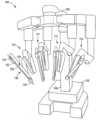
도 1은 예시적인 실시예에 따르는 환자 측 카트의 사시도이다.
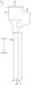
도 2는 예시적인 실시예에 따르는 캐뉼라의 측면도이다.
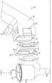
도 3은 예시적인 실시예에 따르는 캐뉼라 마운트 시스템의 부품들에 관한 분해도이다.
도 4는 예시적인 실시예에 따르는 캐뉼라 마운트 시스템의 분해도이다.
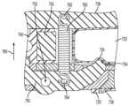
도 5는 도 4의 캐뉼라 마운트 시스템의 횡단방향 단면이 나타나 있는 부분 사시도이다.
도 6은 예시적인 실시예에 따르는 안착된 스프링의 단면도이다.
도 7은 도 4의 캐뉼라 마운트 시스템의 길이방향 단면이 나타나 있는 부분 사시도이다.
도 8에는 핸들이 눌려있는 포지션에 있는 상태의 도 4의 캐뉼라 마운트 시스템의 사시도가 나타나 있다.
도 9에는 클램핑 아암이 열린 포지션에 있고 캐뉼라가 부분적으로 삽입되어 있는 상태의 도 4의 캐뉼라 마운트 시스템이 나타나 있다.
도 10에는 핸들이 눌려있지 않은 포지션에 있는 상태의 도 4의 캐뉼라 마운트 시스템이 나타나 있다.
도 11에는 클램핑 아암이 닫힌 포지션에 있고 캐뉼라가 완전히 삽입되어 있는 상태의 도 4의 캐뉼라 마운트 시스템이 나타나 있다.
도 12는 다른 예시적인 실시예에 따라 내부 부분들이 도시되어 있는 캐뉼라 마운트 시스템의 분해도이다.
도 13은 도 12의 캐뉼라 마운트 시스템의 부분적인 내부가 나타나 있는 평면도이다.
도 14는 그 내부 부분들이 도시되어 있는 도 12의 캐뉼라 마운트 시스템의 부분 평면도이다.
도 15는, 그 내부 부분들이 도시되어 있되 부분적으로 삽입되어 있는 캐뉼라가 나타나 있는 도 12의 캐뉼라 마운트 시스템의 부분 평면도이다.
도 16은 완전히 삽입되어 있는 캐뉼라가 나타나 있는 도 12의 캐뉼라 마운트 시스템의 부분 평면도이다.
도 17은 또 다른 예시적인 실시예에 따르는 캐뉼라 마운트 시스템의 분해 사시도이다.
도 18은 예시적인 실시예에 따르는 캐뉼라의 측면도이다.
도 19는, 그 내부 부분들이 도시되어 있되 도 17의 예시적인 실시예에 관한 캐뉼라와 캐뉼라 마운트의 부분 사시도이다.
도 20은, 그 내부 부분들이 도시되어 있되 도 17에 관한 캐뉼라와 캐뉼라 마운트의 다른 부분 사시도이다.
도 21은 예시적인 실시예에 따르는 도 17의 캐뉼라 마운트 시스템에서 사용되는 이동가능한 블록의 사시도이다.
도 22는 예시적인 실시예에 따르는 도 17의 캐뉼라 마운트 시스템에서 사용되는 클램핑 아암의 사시도이다.
도 23은 그 내부 부분들이 도시되어 있는 도 17의 캐뉼라 마운트와 함께 장착된 포지션에 있는 캐뉼라의 부분 평면도이다.
도 24는 그 내부 부분들이 도시되어 있는 예시적인 실시예에 따르는 잠금 부재를 포함하는 캐뉼라 마운트에 장착된 캐뉼라의 측면도이다.
도 25는 다른 예시적인 실시예에 따르는 캐뉼라 마운트의 부분 분해도이다.
도 26은 다른 예시적인 실시예에 따르는 바디 벽 속에 삽입된 캐뉼라의 부분 측면도이다.
도 27은 다른 예시적인 실시예에 따르는 캐뉼라 살균 어댑터에 장착된 캐뉼라의 부분 사시도이다.
도 28은 도 27의 영역(28)의 확대도이다.
도 29는 다른 예시적인 실시예에 따르는 캐뉼라 살균 어댑터의 측면도이다.The present invention can be understood from the detailed description of the invention that follows only or in conjunction with the accompanying drawings. The drawings are included to provide a further understanding of the invention, and are incorporated in or constitute a part of this specification. The drawings depict one or more illustrative embodiments of the present invention and are used in conjunction with this specification to describe specific principles or operations.
1 is a perspective view of a patient side cart according to an exemplary embodiment.
2 is a side view of a cannula according to an exemplary embodiment.
3 is an exploded view of components of a cannula mount system according to an exemplary embodiment.
4 is an exploded view of a cannula mount system according to an exemplary embodiment.
FIG. 5 is a partial perspective view showing a cross-sectional view of the cannula mount system of FIG. 4;
6 is a cross-sectional view of a seated spring according to an exemplary embodiment.
7 is a partial perspective view showing a longitudinal section of the cannula mount system of FIG. 4;
FIG. 8 shows a perspective view of the cannula mount system of FIG. 4 with the handle in a depressed position.
9 shows the cannula mount system of FIG. 4 with the clamping arm in an open position and the cannula partially inserted.
FIG. 10 shows the cannula mount system of FIG. 4 with the handle in a non-depressed position.
11 shows the cannula mount system of FIG. 4 with the clamping arm in a closed position and the cannula fully inserted.
12 is an exploded view of the cannula mount system with internal parts shown, according to another illustrative embodiment.
13 is a top plan view showing a partial interior of the cannula mount system of FIG. 12;
Fig. 14 is a partial plan view of the cannula mount system of Fig. 12 showing its internal parts;
FIG. 15 is a partial plan view of the cannula mount system of FIG. 12 showing the cannula partially inserted, with its internal parts shown;
16 is a partial plan view of the cannula mount system of FIG. 12 showing the cannula fully inserted.
Fig. 17 is an exploded perspective view of a cannula mount system according to another exemplary embodiment.
18 is a side view of a cannula according to an exemplary embodiment.
Fig. 19 is a partial perspective view of the cannula and cannula mount of the exemplary embodiment of Fig. 17 with internal parts thereof shown;
Fig. 20 is another partial perspective view of the cannula and cannula mount with respect to Fig. 17, showing the internal parts thereof;
Fig. 21 is a perspective view of a movable block used in the cannula mount system of Fig. 17 according to an illustrative embodiment;
Fig. 22 is a perspective view of a clamping arm used in the cannula mount system of Fig. 17 according to an exemplary embodiment;
FIG. 23 is a partial plan view of the cannula in a mounted position with the cannula mount of FIG. 17 showing its internal parts;
24 is a side view of a cannula mounted to a cannula mount including a locking member according to an exemplary embodiment with internal portions thereof shown.
25 is a partially exploded view of a cannula mount according to another exemplary embodiment.
26 is a partial side view of a cannula inserted into a body wall according to another exemplary embodiment.
27 is a partial perspective view of a cannula mounted on a cannula sterile adapter according to another exemplary embodiment.
FIG. 28 is an enlarged view of area 28 of FIG. 27 .
29 is a side view of a cannula sterile adapter according to another exemplary embodiment.
예시적인 실시예들이 도시되어 있는 첨부의 도면들과 본 상세한 설명이 제한하는 것으로 여겨져서는 안된다. 균등물을 포함하여 본 발명의 상세한 설명과 청구범위의 범위를 벗어나지 않으면서 여러 가지 기계적인 변경, 구성요소적인 변경, 구조적인 변경, 전기적인 변경 및 조작상 변경이 행해질 수 있다. 어떤 경우에는 본 명세서를 명료하게 하기 위하여 잘 알려진 구조와 기술은 상세하게 나타나 있지 않거나 설명되어 있지 않는다. 2 이상의 숫자로 되어 있는 유사한 부재번호는 동일하거나 유사한 요소들을 나타낸다. 게다가, 일 실시예를 참조하여 상세하게 기술되어 있는 요소들 및 관련 부재들은 실제 필요한 경우라면 특별히 나타나 있거나 기술되어 있지 않은 다른 실시예들에 포함될 수 있다. 예를 들어, 요소가 일 실시예를 참조하여서는 상세하게 기술되어 있지만 제 2 실시예를 참조하여서는 기술되어 있지 않는 경우라도, 요소는 제 2 실시예에 포함되어 있는 것으로 주장될 수 있다.The accompanying drawings and this detailed description, in which exemplary embodiments are shown, should not be considered limiting. Various mechanical, componential, structural, electrical and operational changes may be made without departing from the scope of the description and claims of the present invention, including equivalents. In some instances, well-known structures and techniques have not been shown or described in detail in order to clarify the present disclosure. Like numbers of two or more digits indicate the same or similar elements. In addition, elements and related members that are described in detail with reference to one embodiment may be included in other embodiments not specifically shown or described if actually necessary. For example, even if an element is described in detail with reference to one embodiment but not with reference to a second embodiment, the element may be claimed to be included in the second embodiment.
본 명세서와 첨부된 청구범위를 위하여, 달리 지시되지 않는 한, 수량, 퍼센트 또는 비율을 표현하는 모든 부재번호와 본 명세서와 청구범위에서 사용되는 다른 수치는 모든 경우에 있어서 "약"이라는 용어로 이미 그렇게 수정되지 않은 범위까지 수정되는 바와 같이 이해되어야 한다. 따라서, 이와 반대로 지시되지 않는 한, 다음에 오는 명세서와 첨부의 청구범위에서 설명되는 숫자 파라미터들은 구하고자 하는 원하는 특성에 따라 달라질 수 있는 근사값이다. 최소한 본 청구범위의 범위에 대한 균등론의 적용을 제한하려는 시도만큼은 아니더라도, 각각의 숫자 파라미터들은 적어도 보고된 유효 자릿수의 숫자의 관점에서 보통의 반올림 기법을 적용하여 해석되어야 한다.For the purposes of this specification and appended claims, unless otherwise indicated, all reference numbers expressing quantities, percentages or ratios and other numerical values used in this specification and claims are in all cases already indicated by the term "about". It should be understood as modified to the extent not so modified. Accordingly, unless indicated to the contrary, the numerical parameters set forth in the following specification and appended claims are approximations that may vary depending on the desired property sought. At least not so much as an attempt to limit the application of the doctrine of equivalents to the scope of the claims, each numerical parameter should at least be construed in light of the number of reported significant digits and applying ordinary rounding techniques.
본 명세서와 첨부의 청구범위에서 사용되는 바와 같이 단수 형태들(영문 명세서 원문상 "a", "an", "the")과 다른 단어의 단수적인 사용은 다른 지시대상으로 분명하면서도 명확하게 제한되지 않는 한 복수의 지시대상들을 포함한다는 점을 유의한다. 본 명세서에서 사용되는 바와 같이, "포함한다(include)"라는 용어와 그 문법적인 변형들을 제한하려는 것은 아니므로, 리스트 내의 아이템들의 열거는 대체되거나 나열된 아이템들에 추가될 수 있는 다른 유사한 아이템들을 배제하는 것은 아니다.As used in this specification and the appended claims, the singular forms ("a", "an", "the" in the original English specification) and the use of the singular of other words are expressly and explicitly not limited to other referents. Note that multiple referents are included unless otherwise specified. As used herein, the term "include" and its grammatical variations are not intended to be limiting, so that enumeration of items in a list excludes other similar items that may be substituted or added to the listed items. It's not.
나아가, 본 상세한 설명의 용어는 본 명세서나 청구범위를 제한하려는 것은 아니다. 예를 들어, "~밑에", "하부", "~위에", "상부", "근위(방향)", "원위(방향)" 및 이와 유사한 공간적으로 상대적인 용어들은 도면에 도시된 바와 같이 다른 요소나 부재에 대한 어느 요소나 부재의 관계를 기술하는데 사용될 수 있다. 이들 공간적으로 상대적인 용어들은 도면에 나타나 있는 포지션과 배향에 추가하여 사용중이거나 조작중인 디바이스의 상이한 포지션(즉 위치)과 배향(즉 회전 배치상태)을 포함하는 것으로 의도되어 있다. 예를 들어, 도면 상의 디바이스가 뒤집히는 경우라면, 다른 요소들이나 부재들 "아래에", 또는 "밑에" 있는 것으로 기술된 요소들은 다른 요소들이나 부재들의 "위쪽에" 또는 "위에" 있을 것이다. 따라서, "~아래에"라는 예시적인 용어는 위쪽이나 아래쪽에 있는 포지션과 배향 모두를 포함할 수 있다. 디바이스는 이와 달리(90도 회전되거나 다른 배향으로) 배향될 수 있고, 공간적으로 상대적인 서술어가 적절히 설명되어 본 명세서에서 사용될 수 있다. 수술 기구들의 상대적인 근위 방향과 원위 방향은 도면에 표지되어 있다.Further, language in this detailed description is not intended to limit either the specification or the claims. For example, "below", "lower", "above", "upper", "proximal (direction)", "distal (direction)" and similar spatially relative terms may be used in other words as shown in the figures. Can be used to describe the relationship of any element or element to an element or element. These spatially relative terms are intended to include different positions (ie positions) and orientations (ie rotational configurations) of the device in use or operation in addition to the positions and orientations shown in the figures. For example, if a device in a figure is inverted, elements described as “beneath” or “beneath” other elements or elements will be “above” or “above” the other elements or elements. Thus, the exemplary term "below" may include both a position and an orientation of being above or below. The device may be otherwise oriented (rotated 90 degrees or at other orientations) and spatially relative descriptors may be used herein as appropriate. The relative proximal and distal directions of the surgical instruments are labeled in the figure.
본 명세서에는 캐뉼라를 수술 시스템의 환자 측 카트의 매니퓰레이터 아암에 장착하기 위한 여러 가지 캐뉼라 마운트 시스템이 고려되어 있다. 예시적인 실시예들은 제조 공차 때문에 크기가 달라질 수 있는 캐뉼라들을 확실하게 파지할 수 있다. 예시적인 실시예들은, 마운트를 열린 포지션과 닫힌 포지션 사이로 이동시키는데 사용되는 걸쇠 뭉치들을 한 손으로 조종할 수 있게 하는 것과 같이, 캐뉼라들이 단순하면서도 신속하고 확실하게 장착되고 제거되는 것을 가능하게 할 수도 있다. 예시적인 실시예들은 또한 캐뉼라가 완전히 장착되었는지의 판정을 용이하게 하는데, 이는 사용자가 캐뉼라에 힘을 가하여 장착되게 하는 일이 일어나는 것을 없애거나 최소화한다. 여러 가지 예시적인 실시예들에서, 캐뉼라의 장착은 캐뉼라 마운트에 의해 부분적으로 작동될 수 있다. 나아가, 캐뉼라 마운트의 구조는 캐뉼라를 장착하는 경우 캐뉼라와 마운트 사이의 적합한 정렬을 용이하게 할 수 있다.Several cannula mount systems are contemplated herein for mounting a cannula to a manipulator arm of a patient side cart of a surgical system. Exemplary embodiments can reliably grip cannulas that may vary in size due to manufacturing tolerances. Exemplary embodiments may allow for simple, quick, and secure mounting and removal of cannulas, such as allowing one-handed manipulation of the clasps used to move the mount between open and closed positions. . Exemplary embodiments also facilitate determining whether a cannula is fully seated, which eliminates or minimizes the occurrence of a user forcing the cannula to seat it. In various exemplary embodiments, the mounting of the cannula may be actuated in part by the cannula mount. Furthermore, the structure of the cannula mount may facilitate proper alignment between the cannula and the mount when mounting the cannula.
본 발명의 여러 가지 예시적인 실시예들에는 수술 시스템을 위한 캐뉼라 마운트들이 고려되어 있다. 마운트는 캐뉼라의 일 부분을 수용하는 구멍을 가지는 바디를 포함한다. 마운트의 피벗가능한 클램핑 아암은 캐뉼라를 클램핑하기 위해서(여기에서 '클램핑하다(clamp)'라는 것은 클램프와 같은 수단으로 어떤 대상을 고정하는 동작 등을 의미하고, 이와 관련하여 '클램핑(clamping)'은 클램프와 같은 수단으로 고정하는 동작이나 고정된 상태 또는 클램프와 같은 수단으로 고정하는 용도 등을 의미하며, 이는 명세서 전체로 동일함) 구멍 안에 수용되는 캐뉼라의 부분에 맞닿을 수 있다. 클램핑 아암은 캠 표면을 구비한다. 마운트는 제 1 포지션과 제 2 포지션 사이에서 이동가능한 블록을 더 포함할 수 있다. 블록은 클램핑 아암을 닫힌 포지션으로 작동하기 위해서 제 1 포지션에 있는 클램핑 아암의 캠 표면에 맞닿는 캠 표면을 포함할 수 있는데, 닫힌 포지션에서는 클램핑 아암이 구멍 안에 수용되는 캐뉼라의 부분에 맞닿는다. 클램프 아암은 열린 포지션으로 이동되는 것이 가능할 수 있는데, 열린 포지션에서는 블록이 제 2 포지션에 있는 경우 클램핑 아암은 캐뉼라에 맞닿지 않는다. 클램핑 아암은 클램핑 아암의 운동 범위에 걸쳐 캐뉼라에 맞닿거나 캐뉼라를 클램핑할 수 있고, 클램핑 아암이 다양한 크기의 캐뉼라들을 감당하는 것을 가능하게 한다. 캐뉼라 마운트는, 블록이 제 2 포지션으로부터 제 1 포지션으로 이동하는 경우 블록의 캠 표면은 캐뉼라의 부분이 클램핑 아암에 의해 클램핑될 때까지 클램핑 아암의 캠 표면에 맞닿으면서 슬라이딩하도록 구성될 수 있다. 캐뉼라 마운트는 단일의 클램핑 아암 또는 복수의 클램핑 아암들을 포함할 수 있다. 캐뉼라 마운트가 복수의 클램핑 아암들을 포함하는 경우, 블록은 클램핑 아암들을 닫힌 포지션으로 작동시키기 위해서 제 1 포지션에 있는 각각의 클램핑 아암들에 맞닿을 수 있는데, 닫힌 포지션에서는 클램핑 아암들이 캐뉼라의 부분에 맞닿는다. 클램핑 아암은, 예컨대 스프링에 의해서 제 1 포지션으로 바이어스될 수 있다. 스프링은 블록을 제 1 포지션으로 바이어스하기 위해서 복수의 스프링들을 구비할 수 있다. 캐뉼라의 부분은 금속 부재를 포함할 수 있고, 블록은 금속 부재와 상호작용하기 위해서 자석을 포함할 수 있다. 캐뉼라 마운트는 원격조작식 수술 시스템의 환자 측 카트의 매니퓰레이터 아암과 같은 수술 시스템의 매니퓰레이터 아암 상에 제공될 수 있다.Several exemplary embodiments of the present invention contemplate cannula mounts for surgical systems. The mount includes a body having an aperture to receive a portion of the cannula. The pivotable clamping arm of the mount is used to clamp the cannula ('clamping' here means an action of fixing an object by means such as a clamp, etc., and in this context, 'clamping' means Refers to the operation of fixing by means such as a clamp or the use of fixing by means such as a clamp or the like, which is the same throughout the specification) Can come into contact with the portion of the cannula accommodated in the hole. The clamping arm has a cam surface. The mount may further include a block movable between the first position and the second position. The block may include a cam surface that abuts against a cam surface of the clamping arm in a first position to actuate the clamping arm into a closed position, where the clamping arm abuts against a portion of the cannula received within the bore. The clamp arm may be capable of being moved to an open position, in which the clamping arm does not abut the cannula when the block is in the second position. The clamping arm is capable of abutting or clamping the cannula over the range of motion of the clamping arm and enabling the clamping arm to accommodate cannulas of various sizes. The cannula mount may be configured such that when the block is moved from the second position to the first position, the cam surface of the block slides against the cam surface of the clamping arm until a portion of the cannula is clamped by the clamping arm. A cannula mount may include a single clamping arm or multiple clamping arms. If the cannula mount includes a plurality of clamping arms, the block may abut each clamping arm in a first position to actuate the clamping arms into a closed position, in which the clamping arms abut a portion of the cannula. all. The clamping arm can be biased into the first position, for example by means of a spring. The spring may include a plurality of springs to bias the block into the first position. A portion of the cannula may include a metal member, and the block may include a magnet to interact with the metal member. The cannula mount may be provided on a manipulator arm of the surgical system, such as a manipulator arm of a patient side cart of a teleoperated surgical system.
여러 가지 예시적인 실시예들에는 강성인 재료를 구비하는 제 1 부분과 연성인 재료를 구비하는 제 2 부분을 포함하는 수술 시스템을 위한 캐뉼라 살균 어댑터가 더 고려되어 있다. 캐뉼라 살균 어댑터는 수술 시스템의 캐뉼라 마운트의 클램핑 아암을 수용하는 함몰부를 구비할 수 있다. 함몰부는, 예컨대 캐뉼라 살균 어댑터의 제 1 부분이나 제 2 부분에 위치되어 있을 수 있다. 제 2 부분은, 예컨대 부드러우면서 가요성인 열가소성 엘라스토머와 같은 열가소성 엘라스토머로 만들어질 수 있다. 예시적인 실시예에 따르면, 수술용 드레이프는 제 2 부분에 연결될 수 있다. 다른 예시적인 실시예에 따르면, 수술용 드레이프는 제 1 부분에 연결될 수 있다. 제 1 부분은 캐뉼라 살균 어댑터를 캐뉼라 마운트에 연결하는 유지 부재를 포함할 수 있다.Various exemplary embodiments further contemplate a cannula sterile adapter for a surgical system comprising a first portion comprising a rigid material and a second portion comprising a soft material. The cannula sterile adapter may have a recess to receive a clamping arm of a cannula mount of a surgical system. The recess may be located, for example, in the first part or the second part of the cannula sterile adapter. The second part may be made of a thermoplastic elastomer, for example a soft and flexible thermoplastic elastomer. According to an exemplary embodiment, the surgical drape may be connected to the second part. According to another exemplary embodiment, a surgical drape may be connected to the first portion. The first portion may include a retaining member connecting the cannula sterile adapter to the cannula mount.
도 1을 참조하면, 원격조작식 수술 시스템의 환자 측 카트(100)의 예시적인 실시예가 나타나 있다. 예컨대 "멀티-포트 수술 로봇 시스템 구조(Multi-Port Surgical Robotic System Architecture)"라는 제목으로 2013년 12월 5일자로 공표된 미국 공보 US 2013/0325033, 및 "하드웨어 구속식 원격 센터 로봇 매니퓰레이터를 위한 여유 축 및 자유도(Redundant Axis and Degree of Freedom for Hardware-constrained Remote Center Robotic Manipulator)"라는 제목으로 2013년 12월 5일자로 공표된 미국 공보 US 2013/0325031에 기술되어 있는 바와 같이, 원격조작식 수술 시스템은 환자 측 카트의 기구들을 제어하기 위해서 사용자로부터 입력값을 수신하기 위한 의사 콘솔(미도시)뿐만 아니라 보조 제어/시각 카트(미도시)를 더 포함할 수 있는데, 각각의 이들 명세서는 그 전체로 참조사항으로 본 명세서에 통합되어 있다. 본 발명의 원리를 이용할 수 있는 원격조작식 수술 시스템의 제한없는 예시적인 실시예들은 캘리포니아 서니베일 소재의 인튜어티브 서지컬 인코포레이티드로부터 입수가능한 다빈치(da Vinci®) Si(모델 넘버 IS3000), 다빈치 Si 수술 시스템, 싱글 사이트 다빈치 수술 시스템 또는 다빈치 Xi 수술 시스템을 포함한다.Referring to FIG. 1 , an exemplary embodiment of a
환자 측 카트(100)는 베이스(102), 메인 칼럼(104), 및 메인 칼럼(104)에 연결되는 메인 붐(106)을 포함할 수 있다. 환자 측 카트(100)는 메인 붐(106)에 각각 연결될 수 있는 복수의 매니퓰레이터 아암들(110, 111, 112, 113)을 포함할 수도 있다. 매니퓰레이터 아암들(110, 111, 112, 113)은 기구(130)가 장착될 수 있는 기구 장착부(120)를 각각 포함할 수 있다. 매니퓰레이터 아암들(110, 111, 112, 113)의 부분들은 의사 콘솔에서 사용자에 의해 제공되는 명령들에 따라 수술 과정 동안 조종될 수 있다. 예시적인 실시예에서, 의사 콘솔로부터 전송된 신호(들)나 입력값(들)은 제어/시각 카트로 전송될 수 있는데, 제어/시각 카트는 기구(130)(도 1에서 장착되어 있는 단 하나의 이러한 기구(130)), 및/또는 기구(130)가 환자 측 카트(100)에서 결합되는 매니퓰레이터 아암(110)의 부분들의 조종을 유발하기 위해서 입력값(들)을 해석하고 환자 측 카트(100)에 전송될 명령(들)이나 출력값(들)을 발생시킬 수 있다.The
기구 장착부(120)는 작동 중계 조립체(122)와 캐뉼라 마운트(124)를 구비할 수 있는데, 예시적인 실시예에 따라 기구(130)의 샤프트(132)는 캐뉼라 마운트(124)를 통해 뻗어있고(수술 과정 동안에는 수술 부위 상에 뻗어있음), 기구(130)의 힘 전달 기구(134)는 작동 중계 조립체(122)와 연결되어 있다. 캐뉼라 마운트(124)는 캐뉼라(도 1에는 미도시)를 파지하도록 구성될 수 있는데, 캐뉼라를 통해서 기구(130)의 샤프트(132)는 수술 과정 동안 수술 부위까지 뻗을 수 있다. 작동 중계 조립체(122)는 당해 기술분야에서의 통상의 기술자에게 익숙한 바와 같이, 의사 콘솔에서 입력된 명령들에 대응하도록 제어되어 기구(130)를 작동하기 위해서 힘 전달 기구(134)에 힘을 전달하는 다양한 드라이브와 다른 메커니즘을 포함하고 있을 수 있다.The
도 1의 예시적인 실시예에는 용이하게 도시하기 위하여 매니퓰레이터 아암(110)에만 부착되어 있는 기구(130)가 나타나 있지만, 기구는 매니퓰레이터 아암들(110, 111, 112, 113) 중 어느 하나나 그 각각에 부착될 수 있다. 기구(130)는 엔드 이펙터가 있는 수술 기구일 수 있고, 또는 내시경 영상 기구, 또는 원격 수술 부위에 관한 정보(예컨대 시각화된 것, 전기생리학적 활성, 압력, 유체 유동 및/또는 다른 감지된 데이터)를 제공하기 위해서 수술 과정 동안 이용되는 다른 감지 기구일 수 있다. 도 1의 예시에서, 엔드 이펙터가 있는 수술 기구나 영상 기구는 매니퓰레이터 아암들(110, 111, 112, 113) 중 어느 하나에 부착되어 이와 함께 사용될 수 있다. 그러나, 본 명세서에 기술된 실시예들은 도 1의 예시적인 실시예로 제한되지 않고, 여러 가지 다른 원격조작식 수술 시스템 구성들이 본 명세서에 기술된 예시적인 실시예들과 함께 사용될 수 있다.Although the exemplary embodiment of FIG. 1 shows the
도 2를 살펴보면, 캐뉼라(300)의 예시적인 실시예의 측면도가 나타나 있다. 캐뉼라(300)는 캐뉼라(300)의 근위 단부(304)를 형성하는 보울 섹션(302), 및 보울 섹션(302)으로부터 캐뉼라(300)의 원위 단부(308)까지 뻗어있는 튜브(306)를 포함할 수 있다. 도 2의 배향에 대한 근위 방향과 원위 방향은 표지되어 있다. 도 2의 예시적인 실시예에 나타나 있는 바와 같이, 튜브(306)는 길이(L)를 가질 수 있고, 원위 단부(308)는 직경(D)을 가질 수 있고, 이들 각각은 당해 기술분야에서의 통상의 기술자에게 익숙한 바와 같이 캐뉼라(300)의 원하는 적용처에 따라 달라질 수 있다. 나아가, 도 2의 예시적인 실시예에 나타나 있는 바와 같이, 본 명세서에 기술된 예시적인 캐뉼라 실시예들이 직선형 튜브로 제한되는 것은 아니지만, 튜브(306)는 직선형일 수 있다. 예를 들어, 튜브(306)는 그 대신 곡선형 튜브일 수 있다(예컨대 길이의 전부나 부분을 따라 곡선형 길이방향 축을 가지는 튜브). 예시적인 실시예에 따르면, 튜브(306)는 강성일 수 있다. 그러나, 본 명세서에 기술된 여러 가지 예시적인 실시예들이 강성인 튜브들이 있는 캐뉼라로 제한되는 것은 아니다. 예를 들어, 튜브(306)는, 예컨대 가요성 튜브일 수 있다.Referring to FIG. 2 , a side view of an exemplary embodiment of a
캐뉼라(300)는 환자의 몸 안의 개구를 통해 수술 부위로 삽입될 수 있다. 예를 들어, 캐뉼라의 원위 단부(308)는, 예컨대 절개부, 자연 개구부 또는 포트와 같은 개구를 통해 수술 부위로 삽입될 수 있다. 도 1의 예시적인 실시예의 기구(160)와 같은 수술 기구는 캐뉼라(300)를 통해 수술 부위로 삽입될 수 있다. 예를 들어, 기구는 캐뉼라의 근위 단부(304) 속으로 삽입되어 보울 섹션(302), 튜브(306) 및 캐뉼라(300)의 원위 단부(308)를 통해 수술 부위 쪽으로 전진이동될 수 있다.
예시적인 실시예에 따르면, 캐뉼라(300)는 캐뉼라를 환자 측 카트의 매니퓰레이터 아암에 연결하기 위해서 도 1의 예시적인 실시예의 환자 측 카트(100)의 매니퓰레이터 아암(110, 111, 112, 113)의 캐뉼라 마운트(124)와 같은 캐뉼라 마운트에 부착될 수 있다. 도 2에 도시된 바와 같이, 캐뉼라(300)는 캐뉼라(300)를 매니퓰레이터 아암의 캐뉼라 마운트에 연결하기 위해서 부착부(310)를 포함할 수 있다. 부착부(310)는, 예컨대 예시적인 실시예에 따라 매니퓰레이터 아암의 캐뉼라 마운트 속으로 삽입되어 매니퓰레이터 아암의 캐뉼라 마운트에 의해 파지되도록 구성되어 있는 돌출부일 수 있다. 도 2의 예시적인 실시예에 나타나 있는 바와 같이, 부착부(310)는 캐뉼라(300)의 보울 섹션(302)의 일부일 수 있고, 또는 이와 달리 캐뉼라(300)의 보울 섹션(302)에 접합될 수 있고, 보울 섹션(302)으로부터 돌출되어 있을 수 있다. 아래에서 설명되는 바와 같이, 캐뉼라 살균 어댑터(도 2에는 미도시)는 캐뉼라 마운트와 캐뉼라(300) 사이에 장착될 수 있는데, 캐뉼라 살균 어댑터는 드레이프(도 2에는 미도시)에 연결되어서 캐뉼라 살균 어댑터와 드레이프는 살균 영역과 비살균 영역 사이에 경계를 형성할 수 있다.According to the exemplary embodiment, the
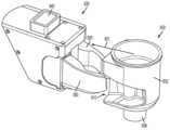
환자 측 카트의 매니퓰레이터 아암에 대한 캐뉼라와 캐뉼라 살균 어댑터의 장착을 개략적으로 설명하기 위하여, 도 3에는 캐뉼라(400), 캐뉼라 살균 어댑터(420), 및 환자 측 카트의 캐뉼라 마운트(430)의 분해도가 도시되어 있다. 캐뉼라 마운트(430)는, 예컨대 도 1의 환자 측 카트(100)의 매니퓰레이터 아암들(110-113) 중 하나에 제공되는 캐뉼라 마운트(124)일 수 있다. 캐뉼라(400)는 도 2의 예시적인 실시예의 캐뉼라(300)와 유사하게 보울 섹션(402), 근위 단부(404), 튜브(406) 및 부착부(410)를 포함할 수 있다. 캐뉼라 살균 어댑터(420)는, 예컨대 캐뉼라 살균 어댑터(420)의 일 부분(421)을 캐뉼라 마운트(430)의 구멍(432) 속으로 삽입함으로써 캐뉼라 마운트(430)에 접합될 수 있다. 당해 기술분야에서의 통상의 기술자에게 익숙한 바와 같이, 캐뉼라 살균 어댑터(420)는 살균 영역과 비살균 영역 사이에 경계를 형성하는 것을 용이하게 할 수 있다. 예를 들어, 수술용 드레이프(426)(점선으로 도 3에 개략적으로 도시됨)는 드레이프(424)의 살균면(426)을 비살균면(428)으로부터 구분하기 위해서 캐뉼라 살균 어댑터(420)에 부착될 수 있다. 캐뉼라(400)의 부착부(410)는 캐뉼라 살균 어댑터(420)의 개구(422) 내면에 들어맞도록 구성결정될 수 있어서, 캐뉼라(400)는 드레이프(424)의 살균면(426) 상에 남아있다. 나아가, 캐뉼라 살균 어댑터(420)가 캐뉼라 마운트(430)에 연결되어 있고 부착부(410)가 캐뉼라 살균 어댑터(420)의 개구(422) 속으로 삽입되는 경우, 캐뉼라(400)는 캐뉼라 마운트(430)에 연결될 수도 있어서 캐뉼라(400)는 수술 과정 동안 캐뉼라 마운트(430)에 의해 파지될 수 있다.To schematically illustrate the mounting of the cannula and cannula sterile adapter to the manipulator arm of the patient side cart, FIG. is shown
예시적인 실시예에 따르면, 캐뉼라 튜브(406)의 일 부분은 캐뉼라(400)를 캐뉼라 마운트(430)에 장착하기 전에, 예컨대 개구부를 통해 환자의 몸 속으로 삽입될 수 있다. 이 경우, 캐뉼라 살균 어댑터(420)는 우선 캐뉼라 마운트(430)에 장착될 수 있고, 캐뉼라 마운트(430)를 포함하는 매니퓰레이터 아암은 캐뉼라 마운트(430)의 구멍(432)이 부착부(410)와 정렬되도록 움직이게 될 수 있다. 순차적으로, 캐뉼라 마운트(430)를 포함하는 매니퓰레이터 아암과 부착부(410)는 부착부(410)가 구멍(432) 내부로 삽입되도록 서로를 향하여 움직이게 될 수 있는데, 살균 어댑터(420)는 캐뉼라(400)를 캐뉼라 마운트(430)에 장착하기 위해서 그 사이에 배치되어 있다. 도 3의 예시적인 실시예에는 캐뉼라 살균 어댑터(420)와 함께 캐뉼라 마운트(430)에 장착되고 있는 캐뉼라(400)가 도시되어 있지만, 캐뉼라(400)는 캐뉼라(400)와 캐뉼라 마운트(430) 사이에 캐뉼라 살균 어댑터(420)가 없는 상태로 캐뉼라 마운트(430)에 직접 장착될 수 있다.According to an exemplary embodiment, a portion of the
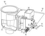
캐뉼라들뿐만 아니라 캐뉼라도 확실하게 파지하는 캐뉼라 살균 어댑터들을 신속하고 용이하면서도 확실하게 장착하기 위한 구조들을 제공하는 것이 바람직하다. 여러 가지 예시적인 실시예들이 이러한 점을 달성하기 위하여 고려되어 있다. 도 4를 살펴보면, 캐뉼라(500), 캐뉼라 살균 어댑터(520), 및 환자 측 카트의 캐뉼라 마운트(530)의 예시적인 실시예에 관한 분해도가 나타나 있다. 캐뉼라 마운트(530)는, 예컨대 도 1의 환자 측 카트(100)의 매니퓰레이터 아암들(110-113) 중 하나 위에 제공되는 캐뉼라 마운트(124)일 수 있다. 캐뉼라(500)는 도 2의 예시적인 실시예의 캐뉼라(300)와 유사하게 보울 섹션(502), 근위 단부(504), 튜브(506)(도 4의 예시적인 실시예에 부분적으로 도시됨) 및 부착부(510)를 포함할 수 있다. 예시적인 실시예에 따르면, 부착부(510)는 아래에서 설명되는 바와 같이 캐뉼라(500)를 캐뉼라 마운트(530)에 장착하는 것을 보조하기 위해서, 예컨대 부착부(510)의 양쪽 측면(도 5에 나타나 있는 바와 같음) 상에 함몰부(512)를 포함할 수 있다. 함몰부(512)는 캐뉼라 살균 어댑터(520)와 캐뉼라 마운트(530)에 대한 캐뉼라(500)의 장착을 용이하게 하도록 구성될 수 있다. 예를 들어, 함몰부(512)들의 각도(513)는 캐뉼라(500)가 장착되는 경우 부착부(510), 캐뉼라 살균 어댑터(520) 및 캐뉼라 마운트(530) 사이에 큰 힘의 적용을 용이하게 하도록 선택될 수 있을 뿐만 아니라, 부착부(510)의 분리도 용이하게 하도록 선택될 수 있다. 예시적인 실시예에 따르면, 각도(513)는, 예컨대 약 50도 내지 약 60도의 범위를 가질 수 있다. 예시적인 실시예에 따르면, 각도(513)는, 예컨대 약 40도일 수 있다.It would be desirable to provide structures for quick, easy and secure mounting of cannulas as well as cannula sterilization adapters that securely grip the cannulas. Several exemplary embodiments are contemplated to accomplish this. Referring to FIG. 4 , an exploded view of an exemplary embodiment of a
캐뉼라 살균 어댑터(520)는 캐뉼라(500)의 부착부(510)를 수용하는 구멍(522)을 포함할 수 있다. 도 3에 관해 상술된 바와 같이, 캐뉼라 살균 어댑터(520)는 살균 영역과 비살균 영역 사이에 경계를 형성하는 것을 용이하게 하기 위해서 수술용 드레이프(도 4에는 미도시)에 부착될 수 있다. 여러 가지 예시적인 실시예들에서, 캐뉼라 살균 어댑터(520)는 캐뉼라 마운트(530)에 대한 캐뉼라 살균 어댑터(520) 및/또는 캐뉼라(500)의 장착을 용이하게 하기 위해서 상이한 부분들(영역들)을 위한 상이한 특성들이 제공될 수 있다. 예를 들어, 캐뉼라 살균 어댑터(520)는 아래에서 보다 상세하게 설명되는 바와 같이 상이한 특성들을 가지는 제 1 부분(524)과 제 2 부분을 포함할 수 있다.The cannula
예시적인 실시예에 따르면, 제 1 부분(524)은, 캐뉼라 살균 어댑터(520)가 캐뉼라 마운트(530)에 장착되는 경우에는 캐뉼라 살균 어댑터(520)를 위한 구조적인 지지뿐만 아니라 캐뉼라(500)가 캐뉼라 살균 어댑터(520)에 장착되는 경우에는 캐뉼라(500)를 위한 구조적인 지지를 제공하는, 비교적 강성인 재료로 만들어질 수 있다. 비교적 강성인 재료는 제 1 부분(524)의 강도와 강성 때문에 부착부(510)가 캐뉼라 살균 어댑터(520)의 구멍(522) 내부에 삽입되는 경우 캐뉼라(500)의 부착부(510)의 정렬을 용이하게 할 수도 있다. 나아가, 비교적 강성인 재료는, 캐뉼라(500)의 부착부(510)가 그 위에서 용이하게 슬라이딩할 수 있는 저 마찰 표면을 제공함으로써 캐뉼라 살균 어댑터(520) 속으로의 캐뉼라(500)의 삽입과 정렬을 용이하게 할 수 있는, 매끄러운 저 마찰 재료일 수 있다. 추가적으로, 제 1 부분(524)은 캐뉼라(500)가 캐뉼라 마운트(530)에 장착되는 경우 클램핑 힘과 바디 벽 힘과 같은, 캐뉼라(500)와 캐뉼라 마운트(530) 사이에 가해지는 힘을 감당하도록 구성될 수 있다.According to an exemplary embodiment,
제 1 부분(524)은, 예컨대 폴리카보네이트, 아크릴로니트릴 부타디엔 스티렌(acrylonitrile butadiene styrene; ABS), 폴리카보네이트/ABS, 폴리우레탄, 및 당해 기술분야에서의 통상의 기술자에게 익숙한 다른 플라스틱과 같은 플라스틱 재료로 만들어질 수 있다. 저 마찰 표면은, 캐뉼라 마운트(530)에 가해지는 거는 힘이 거는 동작 동안 캐뉼라(500)를 장착 포지션이 되게 잡아당기는 경우 캐뉼라(500)의 슬라이딩을 용이하게 함으로써 캐뉼라(500)를 캐뉼라 마운트(530)에 거는 것을 보조할 수도 있다. 예시적인 실시예에 따르면, 캐뉼라 살균 어댑터(520)는 캐뉼라(500)의 삽입 및/또는 제거를 용이하게 하기 위해서 윤활제가 처리될 수 있다. 윤활제는, 예컨대 캐뉼라 살균 어댑터(520)의 표면에 도포되는 폴리테트라플루오로에틸렌(polytetrafluoroethylene; PTFE) 또는 당해 기술분야에서의 통상의 기술자에게 익숙한 다른 윤활제의 드라이 코팅일 수 있다. 다른 예시에서, 윤활 충진제(lubricant filler)는 제 1 부분(524) 및/또는 제 2 부분(526)의 재료와 같은 캐뉼라 살균 어댑터(520)의 재료에 추가될 수 있다. 윤활 충진제는, 예컨대 실리콘 오일, PTFE, 또는 당해 기술분야에서의 통상의 기술자에게 익숙한 다른 윤활제일 수 있다. 제 1 부분(524)은, 예컨대 도 3에 관하여 상술된 바와 같이 수술용 드레이프(도 4에는 미도시)에 연결되는 캐뉼라 살균 어댑터(520)의 부분일 수 있는데, 드레이프의 측면 상의 살균 영역은 캐뉼라(500)를 향하고 있고 드레이프의 측면 상의 비살균 영역은 캐뉼라 마운트(530)를 향하고 있다.
여러 가지 예시적인 실시예들에서, 살균 어댑터는 크기, 형상, 및/또는 캐뉼라 마운트와 캐뉼라 모두와의 그 상호작용을 용이하게 하는 표면 프로파일과 부재들을 포함하는 구성을 가질 수 있다. 도시되어 있는 예시적인 실시예들을 참조하여 아래에서 더 설명되는 바와 같이, 이러한 구성들은 사용자가 캐뉼라와 캐뉼라 어댑터를 캐뉼라 마운트 속으로 삽입할 수 있는 용이성을 향상시킬 수 있고, 그리고/또는 여러 가지 피스들의 부착에 관한 안전성을 향상시킬 수 있다.In various exemplary embodiments, a sterile adapter may have a size, shape, and/or configuration that includes members and a surface profile that facilitates its interaction with both the cannula mount and the cannula. As will be described further below with reference to the exemplary embodiments shown, these configurations can enhance the ease with which a user can insert the cannula and cannula adapter into the cannula mount and/or the use of the various pieces. Safety related to attachment can be improved.
예시적인 실시예에 따르면, 캐뉼라 살균 어댑터(520)의 구멍(522)은, 예컨대 캐뉼라 살균 어댑터(520) 내부에의 캐뉼라(500)의 장착을 용이하게 하기 위해서 캐뉼라(500)의 부착부(510)의 형상에 대응하는 형상을 가지는 캐뉼라 살균 어댑터(520) 안에 개구를 형성한다. 예를 들어, 캐뉼라 살균 어댑터(520)는 구멍(522)에 의해 형성된 개구로부터 캐뉼라 살균 어댑터(520) 속으로 뻗어있는 리세스(575)를 둘러싸는 측벽(523)을 가진다. 예시적인 실시예에 따르면, 부착부(510)는 보울 섹션(502)으로부터 멀어지는 방향으로 테이퍼형상이 되어있다. 예를 들어, 리세스(575)와 둘러싸인 측벽(523)은 방향(521)을 따라, 예컨대 캐뉼라 마운트(530) 속으로의 살균 어댑터(520)의 삽입 방향을 향하는 방향으로 테이퍼형상이 될 수 있다. 나아가, 나타나 있는 바와 같이, 리세스(575)와 측벽(523)은 삽입 방향으로 약간 기다랄 수 있는데, 리세스(575)는 캐뉼라(500)의 부착부(510)의 형상에 대응하는 형상을 가지고 측벽(523)의 외측 표면 프로파일은 살균 어댑터(520)가 캐뉼라 마운트(530) 내부에 수용되는 공간에 대체로 대응하는 형상을 가진다.According to an exemplary embodiment, the
나아가, 도 26을 참조하여 설명되는 바와 같이, 캐뉼라 부착부의 근위 표면과 원위 표면은 테이퍼형상이 될 수 있다. 도 4를 참조하면, 측벽(523)의 외측 표면들은 캐뉼라 마운트(530) 속으로의 캐뉼라 어댑터(520)의 삽입을 보조하기 위해서 라운드처리되고 테이퍼형상이 될 수 있다. 예를 들어, 캐뉼라 살균 어댑터(520)의 측벽(523)의 근위 외측 표면(570)과 원위 외측 표면(572)(그 방향은 도 4의 근위-원위 방향과 같이 캐뉼라가 도 4에서 바라보아 뻗어있는 방향에 대하여 고려되어 있음)은 도 47에 도시된 바와 같이 테이퍼형상이 될 수 있다. 나아가, 대체로 반대방향으로 향하고 있는 외측 측면 표면(576)들(도 4에서는 이러한 표면이 하나만 보임)은 리세스(575)의 형상이 부착부(510)의 형상에 대응하도록 리세스(575)의 4개의 측면을 형성하기 위해서 테이퍼형상이면서 표면들(570, 572)과 협력할 수 있다. 측벽(523)은 도 5에 도시된 바와 같이 원위 내측 표면(582), 근위 내측 표면(도시되지 않았지만 대체로 원위 내측 표면(582)을 향하고 있음) 및 내측 측면 표면(586)들과 같은, 외측 표면들(570, 572, 576)에 대응하는 내측 표면들을 더 포함할 수 있다. 내측 표면들은, 예컨대 외측 표면들(570, 572, 576)과 유사한 방식으로 테이퍼형상이 될 수 있고, 리세스(575)는 그 형상이 부착부(510)의 형상에 대응하도록 리세스(575)의 4개의 측면들을 형성할 수 있다. 예시적인 실시예에 따르면, 측벽(523)의 내측 표면들은 정사각 절두 형상을 가지는 리세스(575)를 제공할 수 있다. 따라서, 리세스(575)를 형성하는 측벽(523)은 도 4와 도 5에 도시된 바와 같이 방향(521)을 따라 테이퍼형상이 되는 4개의 내측 표면들(예컨대 원위 내측 표면(582)과 근위 내측 표면과 같이 대체로 서로 향하고 있는 첫번째 쌍을 이루는 내측 표면들, 및 대체로 반대방향으로 향하고 있는 두번째 쌍을 이루는 표면들)을 포함할 수 있다. 측벽(523)의 외측 표면들은 도 4와 도 5에 도시된 바와 같이 방향(521)을 따라 테이퍼형상이 될 수도 있다. 측벽(523)의 외측 표면들은, 예컨대 캐뉼라 살균 어댑터(520)의 제 2 부분(526) 안에 정사각 절두 형상을 가지는 캐뉼라 살균 어댑터(520)를 제공할 수도 있다. 캐뉼라 살균 어댑터(520)의 측벽(523)의 내측 표면 및/또는 외측 표면은, 예컨대 캐뉼라 살균 어댑터(520)의 테이퍼 형상을 제공하기 위해서 그 형상이 곡선형이거나 편평(예컨대 선형)할 수 있는데, 이는 마운트(530) 속으로의 캐뉼라 살균 어댑터(520)의 삽입 및 캐뉼라 살균 어댑터(520)의 리세스(575) 속으로의 캐뉼라 부착부(510)의 삽입을 용이하게 한다. 나아가, 측벽(523)의 내측 표면들은 2개의 쌍을 이루는 대체로 반대방향으로 배치되어 있는 테이퍼형상 표면들을 형성할 수 있고, 각각의 쌍을 이루는 표면들은 대체로 서로를 향하여 향하고 있다.Further, as described with reference to FIG. 26 , the proximal and distal surfaces of the cannula attachment may be tapered. Referring to FIG. 4 , the outer surfaces of
캐뉼라 살균 어댑터(520)는 아래에서 설명되는 바와 같이 캐뉼라(500)를 캐뉼라 마운트(530)에 장착하는 것을 보조하기 위해서 함몰부 또는 다른 유사한 표면 부재들을 포함할 수 있다. 예시적인 실시예에 따르면, 측벽(523)의 외측 표면(576)들은 함몰부(527)들을 포함한다. 함몰부(527)는, 예컨대 캐뉼라 살균 어댑터(520)의 각각의 양쪽 외측 표면(576)들 상에 위치될 수 있다(도 5의 예시적인 실시예에 나타나 있는 바와 같음). 함몰부(527)는, 예컨대 하나 이상의 곡선형 표면들로 형성될 수 있고, 또는 도 5에 도시된 바와 같이 복수의 편평한 선형 표면들로 형성될 수 있다. 함몰부(527)는 그 형상이 대체로 마운트(530)의 클램핑 아암들의 팁들에 대응할 수 있는데, 이는 아래에서 설명될 것이다. 따라서, 부착부(510)의 형상에 대응하는 형상을 가지는 리세스(575)를 형성하는 측벽(523)은 그 형상이 대응하는 함몰부(527)를 더 포함할 수 있다.Cannula
예시적인 실시예에 따르면, 측벽(523)의 내측 표면들(예컨대 내측 측면 표면(586)들)은 리세스(575) 속으로 뻗어있는 돌출형상부(590)들을 포함한다. 돌출형상부(590)는 그 형상이 캐뉼라(500)의 부착부(510) 안의 함몰부(512)에 대응할 수 있다. 돌출형상부(590)들은, 예컨대 함몰부(527)로부터 측벽(523)의 반대쪽 측면 상에 위치되어 있는 돌출형상부(590)들을 통해 함몰부(527)들의 위치 및/형상에 대응할 수 있다. 돌출형상부(590)들은, 예컨대 하나 이상의 곡선형 표면으로 형성될 수 있고, 또는 도 5에 도시된 바와 같이 복수의 편평한 선형 표면(584)들로 형성될 수 있다. 돌출형상부(590)들의 편평한 표면(584)들은 그 형상이 부착부(510)에 상응하도록 부착부(512)의 함몰부(512)와 실질적으로 동일한 각도(513)로 경사져 있을 수 있다. 함몰부(527)의 편평한 표면들(예컨대 표면(574)들)은 예시적인 실시예에 따라 부착부(512)의 함몰부(512)와 실질적으로 동일한 각도(513)로 유사하게 경사져 있을 수 있다.According to the exemplary embodiment, the inner surfaces of the side wall 523 (eg inner side surfaces 586 ) include
도면에 도시되어 있는 함몰부들과 돌출형상부들은 원래 예시적인 것이고, 본 발명에는, 예컨대 다른 개수의 함몰부들 및/또는 돌출형상부들, 및 함몰부들 및/또는 돌출형상부들을 위한 다른 기하학적 형상부들과 같은 함몰부들과 돌출형상부들로 된 다른 구성들이 고려되어 있다. 나아가, 다른 표면 부재들은, 예컨대 마운트, 캐뉼라 살균 어댑터와 캐뉼라 사이에 확실한 맞닿음(engagement; 여기에서 '맞닿음'이라 함은 어떤 대상이 다른 대상과 특정 지점이나 특정 면에서 단순히 맞닿는 것뿐만 아니라 두 대상이 서로 맞물리는 동작이나 그러한 상태 등을 포함하는 광의의 '결합'을 의미하며, 이는 명세서 전체로 동일함)을 제공하기 위해서 캐뉼라의 부착부 및/또는 캐뉼라 마운트의 상보적인 부재들과 짝을 이루도록 캐뉼라 살균 어댑터에 제공될 수 있다.The depressions and protrusions shown in the drawings are exemplary in nature and the present invention includes, for example, other numbers of depressions and/or protrusions, and other geometrical features for the depressions and/or protrusions. Other configurations of the same depressions and protrusions are contemplated. Further, other surface members may include, for example, a mount, a secure engagement between the cannula sterile adapter and the cannula ('contact' here means not only a simple contact of one object with another object at a specific point or surface, but also two It means 'coupling' in a broad sense, including the action or state in which objects engage with each other, which is the same throughout the specification). A cannula sterile adapter may be provided to achieve this.
예시적인 실시예에 따르면, 캐뉼라 살균 어댑터(520)의 제 1 부분(524)은 측벽(523), 결과적으로는 함몰부(527)들뿐만 아니라 돌출형상부(590)들을 구비할 수 있다. 도 29를 살펴보면, 캐뉼라 살균 어댑터(1320)의 예시적인 실시예의 측면도는 제 1 부분(1324)와 제 2 부분(1326)을 포함하고 있는 것으로 나타나 있다. 본 명세서의 여러 가지 예시적인 실시예에 기술된 바와 같이, 제 1 부분(1324)은, 예컨대 비교적 강성인 재료로 만들어질 수 있고, 제 2 부분(1326)은, 예컨대 비교적 연성인 재료로 만들어질 수 있다. 예시적인 실시예에 따르면, 제 1 부분(1324)은 도 5의 예시적인 실시예에 관하여 상술된 바와 같이 캐뉼라를 캐뉼라 마운트에 장착하는 것을 보조하기 위해서 함몰부(1327)를 구비하는 하나 이상의 돌출형상부(1325)를 포함할 수 있다. 따라서, 도 5의 예시적인 실시예에는 돌출부들(및 함몰부(527)를 형성하는 캐뉼라 살균 어댑터(520)의 제 2 부분(526))이 결여되어 있는 것과 같이 제 1 부분(524)이 도시되어 있지만, 캐뉼라 살균 어댑터의 제 1 부분은 하나 이상의 돌출부(1325)들을 포함하는 도 29의 구성을 포함하여 다른 구성들을 가질 수 있다. 제 1 부분(1324)은, 예컨대 캐뉼라 살균 어댑터(1320)의 측면방향 면들 상에 있는 한 쌍의 돌출부들과 같이 함몰부(1327)들을 구비하는 복수의 돌출부(1325)들을 포함할 수 있다. 예시적인 실시예에 따르면, 제 2 부분(1326)은, 예컨대 제 2 부분(1326)을 돌출부(1325)에 오버몰딩하는 것과 같이 돌출부(1325)에 연결될 수 있다.According to an exemplary embodiment, the
예시적인 실시예에 따르면, 캐뉼라 살균 어댑터(520)의 제 2 부분(526)은 비교적 연성인 재료로 만들어질 수 있다. 비교적 연성인 재료는 제 2 부분(526)이 비교적 용이하게 탄력적으로 변형되는 것을 가능하게 할 수 있는 한편, 살균 영역과 비살균 영역 사이에 경계를 유지하도록 시일을 제공할 수도 있다. 예를 들어, 제 2 부분(526)은 도 3과 관련하여 기술된 바와 같이 수술용 드레이프(도 4에는 미도시)에 연결되는 캐뉼라 살균 어댑터(520)의 부분일 수 있는데, 드레이프의 측면 상의 살균 영역은 캐뉼라(500)를 향하고 있고 드레이프의 측면 상의 비살균 영역은 캐뉼라 마운트(530)를 향하고 있다. 예시적인 실시예에 따르면, 제 2 부분(526)은 제 1 부분(524) 위쪽에 오버몰딩되어 있는 플라스틱 재료로 만들어질 수 있다. 제 2 부분(526)은, 예컨대 열가소성 엘라스토머(thermoplastic elastomer; TPE), 열가소성 폴리우레탄(thermoplastic polyurethane; TPU), 또는 당해 기술분야에서의 통상의 기술자에게 익숙한 다른 플라스틱 재료로 만들어질 수 있다. 예시적인 실시예에 따르면, 캐뉼라 살균 어댑터(520)의 제 2 부분(526)은 아래에서 설명되는 바와 같이 캐뉼라(500)를 캐뉼라 마운트(530)에 장착하는 것을 보조하기 위해서, 예컨대 제 2 부분(526)의 양쪽 측면 상에(도 5의 예시적인 실시예에 나타나 있는 바와 같음) 함몰부(527)(이뿐만 아니라 대응하는 돌출형상부(590)들)를 포함할 수 있다.According to an exemplary embodiment, the
캐뉼라 살균 어댑터(520)는 캐뉼라(500)가 캐뉼라 살균 어댑터(520) 속으로 삽입되거나 캐뉼라 살균 어댑터(520)로부터 후퇴되는 경우와 같이 캐뉼라 살균 어댑터(520)의 변형을 용이하게 하는 구조를 포함할 수 있다. 예시적인 실시예에 따르면, 캐뉼라 살균 어댑터(520)의 제 2 부분(526)은 제 2 부분(526)의 변형을 용이하게 하기 위해서 도 5에 나타나 있는 바와 같이 벨로우즈 구조(528)를 포함할 수 있다. 캐뉼라 살균 어댑터(520)의 제 2 부분(526)은 벨로우즈 구조(528)에 추가하거나 벨로우즈 구조(528)가 없이 제 2 부분(526)의 변형을 가능하게 하기 위해서 비교적 얇은 측벽(523)을 포함할 수 있다. 벨로우즈 구조(528)와 얇은 측벽(523)이 도 5의 예시적인 실시예의 캐뉼라 살균 어댑터(520)에 관하여 기술되어 있지만, 벨로우즈 구조(528)들 및/또는 얇은 측벽(523)은 예시적인 실시예에 따라서 제 1 부분(524)과 제 2 부분(526)을 대신하는 단일의 재료로 만들어지는 캐뉼라 살균 어댑터에서 사용될 수 있다.Cannula
위에서 설명한 바와 같이, 캐뉼라 마운트(530)는 캐뉼라 어댑터에 맞닿는 부재들을 포함할 수 있다. 도 5를 살펴보면, 내부 구조들을 보여주기 위해서 캐뉼라(500), 캐뉼라 살균 어댑터(520) 및 캐뉼라 마운트(530)가 나타나 있다. 예시적인 실시예에 따르면, 캐뉼라 마운트(530)는 캐뉼라 살균 어댑터(520)의 상보적인 유지 부재(525)들과 맞닿는 하나 이상의 유지 부재(541)들을 포함할 수 있다. 유지 부재(525)들은 예시적인 실시예에 따라 캐뉼라 살균 어댑터(520)의 제 1 부분(524)과 함께 하나의 피스로 몰딩될 수 있고, 또는 제 1 부분(524)에 접합되는 별개의 피스로 제공될 수 있다. 캐뉼라 마운트(530)의 유지 부재(541)들은 캐뉼라 살균 어댑터(520)가 캐뉼라 마운트(530)에 장착되는 경우와 같이 캐뉼라 마운트(530)의 바디(536)에 대하여 이동하도록 정렬될 수 있다. 예를 들어, 유지 부재(541)는, 예컨대 스프링(542)에 의하여 맞닿은 포지션으로 바이어스될 수 있다. 따라서, 캐뉼라 살균 어댑터(520)가 캐뉼라 마운트(530)에 장착되는 경우, 캐뉼라 살균 어댑터(520)의 유지 부재(525)는 캐뉼라 마운트(530)의 유지 부재(541)에 맞닿을 수 있고, 상보적인 유지 부재들(525, 541)이 완전히 맞닿을 때까지 처음에는 유지 부재(541)와 스프링(542)이 눌리게 한다. 이러한 완전히 맞닿는 포지션에서, 스프링(542)은 캐뉼라 살균 어댑터(520)를 캐뉼라 마운트(530)에 장착하기 위해서 유지 부재(541)를 맞닿는 포지션으로 바이어스한다. 캐뉼라 살균 어댑터(520)를 연결해제하기 위하여, 유지 부재(541)는, 예컨대 유지 부재(541)의 분리 장치(540)를 눌러서 스프링(542)의 바이어스하는 힘에 대항하여 눌리게 될 수 있다. 도 4에 나타나 있는 바와 같이, 분리 장치(540)는 캐뉼라 마운트(530)의 바디(536)의 외부 표면 상에 노출될 수 있다. 본 명세서에 기술된 여러 가지 실시예들에는, 예컨대 1개의 쌍, 3개의 쌍, 4개의 쌍 또는 그 이상의 개수의 쌍과 같이 다른 개수의 대응하는 유지 부재 쌍(525, 541)이 고려되어 있지만, 도 5의 예시적인 실시예에 나타나 있는 바와 같이, 캐뉼라 살균 어댑터(520)와 캐뉼라 마운트(530)는 2쌍의 대응하는 유지 부재들(525, 541)을 각각 포함할 수 있는데, 유지 부재들(525, 541)은 캐뉼라 살균 어댑터(520)와 캐뉼라 마운트(530)의 마주하는 측면들 상에 있다.As described above, the
캐뉼라 마운트(530)는 사용하기에 용이하면서도 캐뉼라(500)를 안전하고 확실하게 장착하는 여러 가지 구조들을 포함할 수 있다. 도 5에 나타나 있는 바와 같이, 캐뉼라 마운트(530)는 캐뉼라(500)에 맞닿는 한 쌍의 클램핑 아암(550)을 포함할 수 있다. 예를 들어, 캐뉼라(500)의 부착부(510)가 캐뉼라 마운트(530)의 구멍(532) 속으로 삽입되는 경우, 클램핑 아암(550)들의 팁(551)들은 캐뉼라(500)를 캐뉼라 마운트(530)에 장착하기 위해서 부착부(510)의 함몰부(512)에 걸릴 수 있다. 나아가, 캐뉼라 살균 어댑터(520)가 캐뉼라 마운트(530)에 장착되는 경우라면, 부착부(510)는 캐뉼라 살균 어댑터(520)의 구멍(5220) 내부에 삽입될 수 있고, 클램핑 아암(550)의 팁(551)들은 캐뉼라 살균 어댑터(520)의 함몰부(527)들(또는 도 29의 예시적인 실시예의 캐뉼라 살균 어댑터(1320)의 함몰부(1327)들)에 맞닿을 수 있다. 제 2 부분(526)이 비교적 연성이기 때문에, 제 2 부분(526)의 부분과 같은 캐뉼라 살균 어댑터(520)의 일 부분은(예컨대 제 2 부분(526)이 함몰부(527)을 형성하는 경우) 캐뉼라(500)를 캐뉼라 마운트(530)에 장착하기 위해서 클램핑 아암(550)들에 의해 부착부(510)의 함몰부(512)들 속으로 차례로 압축될 수 있다.The
클램핑 아암(550)은 캐뉼라(500)를 장착하고 분리하는 것을 용이하게 하기 위해서 핀(552)을 중심으로 피벗운동하도록 작동될 수 있다. 예시적인 실시예에 따르면, 클램핑 아암(550)은 클램핑 아암(550)을 도 5에 나타나 있는 닫힌(걸린) 포지션으로 맞닿아 이동시키는 이동가능한 블록(554)에 의해 작동될 수 있다. 예를 들어, 블록(554)은 각각의 클램핑 아암(550)들을 맞닿게 하는 클램핑 아암(550)의 캠 팔로워 표면(553)과 같은 캠 표면(556)을 포함할 수 있고, 클램핑 아암(550)을 도 5에 나타나 있는 닫힌 포지션으로 피벗운동하게 한다.Clamping
이동가능한 블록(554)은 캐뉼라(500)를 캐뉼라 마운트(530)에 확실하게 걸기 위해서 이동가능한 블록(554)를 도 5에 나타나 있는 포지션과 같은 닫힌(즉 잠긴)포지션으로 바이어스하는 디바이스를 포함할 수 있다. 예시적인 실시예에 따르면, 스프링(560)은 이동가능한 블록(554)을 도 5에 나타나 있는 포지션으로 바이어스할 수 있다. 스프링(560)은 장착용 블록(562)과 이동가능한 블록(554) 사이에 연결될 수 있지만, 본 명세서에 기술된 여러 가지 실시예들이 이 구조로 제한되지 않고 스프링(560)이 그 대신 캐뉼라 마운트(530)의 바디(536)와 이동가능한 블록(554) 사이에 연결될 수 있다. 예시적인 실시예에 따르면, 캐뉼라 마운트(530)는 스프링(560)이 눌려있는지 여부 및 클램핑 아암(550)이 잠긴 또는 분리된 포지션에 있는지 여부를 추정하기 위해서 이동가능한 블록(554)의 포지션을 탐지하는 센서를 포함할 수 있다. 센서는, 얘컨대 이동가능한 블록(554)이 클램핑 아암(550)을 작동시키기 위해서 전후로 작동됨에 따라 이동가능한 블록(554)이 접촉하는 스위치일 수 있다. 센서로부터의 출력값은, 예컨대 클램핑 아암(550)이 잠긴 또는 분리된 포지션에 있는지 여부를 피드백하기 위해서 수술 시스템의 제어장치로 전송될 수 있다.The
스프링(560)은 예시적인 실시예에 따라 코일 스프링, 또는 당해 기술분야에서의 통상의 기술자에게 익숙한 타입의 스프링일 수 있다. 스프링(560)이 단일의 스프링일 수 있지만, 스프링(560)은 그 대신 복수의 스프링들일 수 있다. 예를 들어, 스프링이 그 평형 길이로부터 변형되는 거리에 비례하여 스프링에 의해 가해지는 힘이 달라지기 때문에, 스프링(560)은 실질적으로 일정하면서도 큰 힘을 스프링(560)이 변형되는 거리를 넘어서 제공하기 위해서 상이한 타입의 복수의 스프링들(예컨대 상이한 스프링 상수들을 가짐)을 포함할 수 있다. 도 6을 살펴보면, 안착된 스프링(600)의 예시적인 실시예는 스프링(560)을 위하여 사용될 수 있는 것으로 나타나 있다. 안착된 스프링(600)은 제 2 스프링(620) 내부에 위치되는 제 1 스프링(610)을 포함한다. 안착된 스프링(600)은 도 5의 장착용 블록(562)과 같이 장착용 블록(602)에 연결될 수 있고, 또는 캐뉼라 마운트(530)의 바디(536)에 장착될 수 있다. 제 1 스프링(610)과 제 2 스프링(620)은 상이한 스프링 상수를 제공하기 위해서 재료 및/또는 기하학적 형상이 상이할 수 있어서, 전체 안착된 스프링(600)은 실질적으로 일정하고 비교적 큰 힘을 안착된 스프링(600)이 압축되는 경우와 같이 안착된 스프링(600)이 변형되는 거리를 넘어 제공한다.
캐뉼라 마운트(530)는 사용자가 이동가능한 블록(554)과 클램핑 아암(550)을 포함하는 캐뉼라 걸쇠 뭉치를 작동시키는 메커니즘을 포함할 수 있다. 도 4에 나타나 있는 바와 같이, 캐뉼라 마운트(530)는 이동가능한 블록(554)을 작동시키는 핸들(534)을 포함할 수 있다. 예시적인 실시예에 따르면, 단일의 핸들(534)은 캐뉼라의 장착과 분리를 용이하게 하기 위해서 제공될 수 있다. 예시적인 실시예에 따르면, 핸들(534)은 사용자가 이동가능한 블록(554), 결과적으로 클램핑 아암(550)들 모두를 작동하는데 사용하는 단일의 메커니즘으로서 제공될 수 있다. 핸들(534)은 사용자가 이동가능한 블록(554), 결과적으로 클램핑 아암(550)들을 한 손으로 작동시킬 수 있게 하므로, 사용자가 캐뉼라(500)를 다른 손으로 조종할 수 있게 한다.The
핸들(534)은 핸들(534)과 이동가능한 블록(554) 사이의 연결을 통해 이동가능한 블록(554)을 작동시킬 수 있다. 도 7을 살펴보면, 여기에는 측면에서 바라본 캐뉼라(500), 캐뉼라 살균 어댑터(520) 및 캐뉼라 마운트(530)의 단면이 나타나 있다. 도 7에 나타나 있는 바와 같이, 핸들(534)은 예시적인 실시예에 따라 링크(535)를 통해 이동가능한 블록(554)에 연결될 수 있다. 핸들(534)이 도 7에서 화살표(537)로 지시되는 방향으로 눌리는 경우, 링크(535)와 이동가능한 블록(554)은 도 7의 방향(539)을 따라 이동된다. 아래에서 설명되는 바와 같이, 이동가능한 블록(554)이 방향(539)을 따라 이동되는 경우, 클램핑 아암(550)들은 캐뉼라(550)가 장착되거나 분리되는 것을 가능하게 하기 위해서 열린 포지션으로 이동된다.The
예시적인 실시예에 따르면, 링크(535)는 핸들(534)을 이동가능한 블록(554)에 연결시킬 수 있으므로, 핸들(534)이 도 7의 방향(537)으로 눌리는 경우, 링크(535)가 방향(539)으로 이동하되 핸들(534)에 연결되는 링크(535)의 일 부분(533)이 방향(531)을 따라 아래쪽을 향하여 이동함에 따라, 링크(535)는 이동가능한 블록(554)의 장축(555)과 정렬되기 시작할 것이다. 결과적으로, 핸들(534)이 처음으로 도 7의 방향(537)을 따라 이동되는 경우, 실질적인 정렬이 링크(535)와 이동가능한 블록(554)의 장축(555) 사이에서 일어나되 핸들(534)과 링크(535) 사이의 각도가 감소하는 경우와 같이 핸들(534)을 작동시키는데 요구되는 힘은 스프링 힘이 증가하는 상태로 처음에는 증가하다가, 나중에는 감소한다. 결과적으로, 핸들(534)이 완전히 눌리면, 핸들(534)은 완전히 눌려있는 포지션으로 남아있을 것인데, 이는 그렇게 하는데 감소된 양의 힘이 필요하기 때문이고, 이는 차례로 캐뉼라(500)를 캐뉼라 마운트(530) 내부에 삽입하고 정렬하는 것 또는 캐뉼라(500)를 캐뉼라 마운트(530)로부터 제거하는 것에 사용자가 집중하는 것을 가능하게 할 수 있다.According to an exemplary embodiment, link 535 may connect handle 534 to
캐뉼라(500)를 장착하기 위한 캐뉼라 마운트(530)의 사용은 도 8-11을 참조하여 이어서 기술될 것이다. 도 8을 살펴보면, 도 5, 도 7 및 도 8의 예시적인 실시예는 핸들(534)이 캐뉼라 마운트(530)의 걸쇠 뭉치를 작동시키기 위해서 방향(537)을 따라 눌려있는 상태로 나타나 있다. 도 9에 나타나 있는 바와 같이, 핸들(534)을 작동시키는 것은 도 7을 참조하여 상술된 바와 같이 이동가능한 블록(554)이 방향(539)을 따라 후진되게 한다. 이동가능한 블록(554)이 방향(539)을 따라 후진되는 경우, 스프링(560)은 압축되고 이동가능한 블록(554)의 캠 표면(556)은 클램핑 아암(550)의 캠 팔로워 표면(553)들로부터 맞닿음해제된다. 스프링은 이동가능한 블록(554)의 캠 표면(556)을 캠 팔로워 표면(553)들과 맞닿도록 더 이상 바이어스하지 않기 때문에, 클램핑 아암(550)들은 도 9에 나타나 있는 열린 포지션으로 자유롭게 피벗운동한다. 도 9에 나타나 있는 열린 포지션에서, 클램핑 아암(550)들의 팁(551)들은, 예컨대 캐뉼라 살균 어댑터(520)의 함몰부(527 또는 1327)와 같은 캐뉼라 살균 어댑터(520)와 맞닿지 않는다.The use of
클램핑 아암(550)들이 도 9에 나타나 있는 열린 포지션에 있는 상태에서, 캐뉼라(500)의 부착부(510)는 이미 캐뉼라 마운트(530)에 장착되어 있는 캐뉼라 살균 어댑터(520)의 구멍(522) 속으로 삽입될 수 있다. 캐뉼라(500)가 환자의 몸 속으로 이미 삽입되어 있을 수 있기 때문에, 부착부(510)를 캐뉼라 살균 어댑터(520) 속으로 삽입하는 것을 포함하여 캐뉼라(500)를 캐뉼라 마운트(530)에 장착하기 위하여 기술된 다음에 오는 이동들은 캐뉼라 마운트(530)를 포함하는 매니퓰레이터 아암을 실질적으로 정지된 캐뉼라(500)에 대하여 이동시킴으로써 달성될 수 있다. 예를 들어, 부착부(510)는 캐뉼라 마운트(530)를 포함하는 매니퓰레이터 아암을 도 9에 나타나 있는 방향(538)을 따라 이동시킴으로써 캐뉼라 살균 어댑터(520) 속으로 삽입될 수 있다.With the clamping
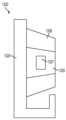
부착부(510)를 캐뉼라 살균 어댑터(520)의 구멍(522) 속으로 삽입하는 경우, 캐뉼라(500)의 이동은 구속될 수 있다. 도 26의 예시적인 실시예에 나타나 있는 바와 같이, 캐뉼라(1100)는 환자의 체벽(1140) 안으로 삽입될 수 있다. 캐뉼라(1100), 캐뉼라 살균 어댑터(1120) 및 캐뉼라 마운트(1130)는 도 5와 도 7-11의 예시적인 실시예에 따라 각각 배열될 수 있다. 체벽(1140) 안으로의 캐뉼라(1100)의 삽입은, 예컨대 도 26의 방향(114)으로 운동의 원격 중심(1142)을 중심으로 피벗운동만하기 위해서 캐뉼라(1100)의 구속되는 이동을 초래한다. 캐뉼라(1100)를 캐뉼라 살균 어댑터(1120)와 캐뉼라 마운트(1130)에 장착하는 경우 피벗 운동을 감당하기 위하여, 캐뉼라 부착부(1110)의 원위 표면(1113)과 근위 표면(1111)의 기하학적 형상은 최적화될 수 있다. 캐뉼라 살균 어댑터의 내측 표면(1121)의 기하학적 형상도 최적화될 수 있다. 예시적인 실시예에 따르면, 표면들(1111, 1113, 1121)은, 예컨대 표면들(1111, 1121)로부터 원격 중심(1142)까지의 거리보다 작은 곡률 반경으로 곡선형일 수 있다. 표면들(1111, 1113, 1121)은, 예컨대 직선 형상, 선형 형상과 같이 곡선형 형상 이외의 다른 형상을 가질 수 있다. 예시적인 실시예에 따르면, 표면들(1111, 1113, 1121)은 2개의 쌍을 이루는 대체로 반대방향으로 배치되어 있는 테이퍼형상 표면들을 제공하고, 각각의 쌍을 이루는 표면들은 서로로부터 멀리 향하고 있다. 표면들(1111, 1113, 1121)을 이러한 방식으로 형상결정함으로써, 캐뉼라 살균 어댑터(1120)의 구멍(1120) 속이나 밖으로의 부착부(1110)의 삽입이나 후퇴는 용이하게 된다.When the
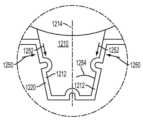
캐뉼라 부착부의 기하학적 형상은 또한 캐뉼라에 가해지는 힘의 관점으로 구성될 수 있다. 도 27을 살펴보면, 캐뉼라(1200)의 예시적인 실시예는 캐뉼라 살균 어댑터(1220)가 장착되어 있는 상태로 나타나 있다. 예컨대 체벽 힘과 같은 힘(1240)은 캐뉼라에 가해질 수 있고, 캐뉼라(1200) 상에 토크를 초래한다. 도 27의 영역에 관한 확대도인 도 28을 살펴보면, 부착부(1210)는 토크를 견디고 캐뉼라 살균 어댑터(1220)로부터의 캐뉼라(1200)의 제거를 방지하거나 최소화하도록 구성될 수 있다. 도 28의 예시적인 실시예에 나타나 있는 바와 같이, 부착부(1210)의 측벽(1212)들은 테이퍼형상이 될 수 있어서, 토크(1242)를 견디기 위해서 측벽(1212)들과 캐뉼라 살균 어댑터(1220) 사이에 가해지는 법선방향 힘(1250)은 캐뉼라 살균 어댑터(1220)로부터 부착부(1210)를 제거하는 토크(1242)를 방지하거나 최소화하기에 충분한 마찰력 성분(1252)을 가진다.The geometry of the cannula attachment can also be configured in terms of the force applied to the cannula. Referring to FIG. 27 , an exemplary embodiment of a
예시적인 실시예에 따르면, 부착부(1210)의 단면은, 예컨대 쐐기 형상의 부착부(1210)를 제공하기 위해서 도 27과 도 28에 도시되어 있는 바와 같이 캐뉼라(1200)의 길이방향 축에 대하여 반경 방향을 따라 테이퍼형상이 될 수 있다. 예를 들어, 측벽(1212)은 부착부(1210)의 길이방향 중심선(1214)에 대하여 각도(1254)로 테이퍼형상이 될 수 있다. 각도(1254)는 예시적인 실시예에 따라, 예컨대 약 8도 내지 약 12도의 범위를 가질 수 있다. 예시적인 실시예에 따르면, 부착부(1210)의 다수의 표면들은 테이퍼형상이 될 수 있다. 도 26에 나타나 있는 바와 같이, 표면들(1111, 1113)은 테이퍼 형상이 될 수 있다. 각각의 표면들(1111, 1113)은 예시적인 실시예에 따라 측벽(1212)들에 대해 실질적으로 수직일 수 있다. 예시적인 실시예에 따르면, 부착부(1210)의 측벽들은 대체로 정사각 절두 형상을 가지는 부착부를 제공한다. 측벽(1212)들과 표면들(1111, 1113)의 테이퍼형상은 사용자가 캐뉼라(1200)를 분리하기 위해서 캐뉼라 마운트(미도시)를 작동시키는 경우 캐뉼라 살균 어댑터(1220)로부터 부착부의 제거를 용이하게 할 수 있다. 예를 들어, 테이퍼형상은 부착부(1210)를 캐뉼라 살균 어댑터(1220) 밖으로 슬라이딩하는 것을 용이하게 할 수 있다.According to an exemplary embodiment, the cross-section of the
도 9를 다시 살펴보면, 부착부(510)는 구멍(522)의 형상에 대응하는 형상을 가질 수 있어서, 부착부(510)는 예시적인 실시예에 따라 특정 배향으로 구멍(522)과 캐뉼라 살균 어댑터(520)의 내부(529) 속에만 들어맞을 수 있다. 따라서, 구멍(522) 내부에서의 부착부(510)의 적당한 정렬은 캐뉼라(500)의 장착 동안 용이하게 되고, 부착부(510)가 구멍(522) 내부에 수용되어 있다면 캐뉼라(500)를 설치하는 사용자는 캐뉼라(500)가 장착을 위하여 적절히 배향되고 정렬된다는 것을 이해할 것이다. 예시적인 실시예에 따르면, 부착부(510)가 구멍(522) 내부에 수용되어 있다면, 캐뉼라(500)는, 예컨대 도 7의 단면도의 평면에 대해 수직인 라인 둘레에서 피벗운동하기 위해서 캐뉼라 마운트(530)에 대한 1자유도만으로 이동할 수 있다. 이 지점에서는 걸린 포지션에 도달하기 위해서 하나의 여유 자유도만 있기 때문에, 사용자는 보다 용이하게 최종 걸린 포지션에 도달하는 이러한 행위를 이용할 수 있다. 예를 들어, 여유 자유도는 도 7의 단면도의 평면에 대해 수직인 라인을 중심으로 하는 회전 자유도이다. 캐뉼라(500)가 부착부(510)를 구멍(522) 속으로 피벗운동시킴으로서 움직여져 있으면, 부착부(510)와 캐뉼라 살균 어댑터(520) 사이의 최종 정렬이 달성될 때까지 사용자는 구멍(522) 속으로의 삽입(예컨대 매니퓰레이터 아암 마운트(530)를 이동시킴으로써 연결됨) 방향을 따라 구멍 내부에서의 부착부(510)의 포지션을 미세 조정할 수 있다. 최종 정렬을 수행하는 것이 용이하게 되는데, 이는 캐뉼라가 모든 다른 자유도로 구속되기 때문이므로, 사용자가 매니퓰레이터 아암을 대략 정확한 방향으로 안내하는 경우라면, 조립상태는 보다 양호하게 정렬될 수 있다.Referring again to FIG. 9 ,
부착부(510)가 도 9의 캐뉼라 살균 어댑터(520) 속으로 삽입됨에 따라, 부착부(510)는 캐뉼라 살균 어댑터(520)의 제 2 부분(526)에 맞닿을 수 있다. 그러나, 제 2 부분(526)이 연성인 재료로 만들어질 수 있기 때문에, 부착부(510)는 제 2 부분(526)을 벌어지도록 변형시킬 수 있고, 부착부(510)가 캐뉼라 살균 어댑터(520)의 내부(529) 속으로 용이하면서도 완전히 삽입되는 것을 가능하게 할 수 있다. 부착부(510)가 캐뉼라 살균 어댑터(520)의 내부(529) 속으로 완전히 삽입되었으면, 캐뉼라 살균 어댑터(520)의 돌출형상부(590)들(또는 도 29의 캐뉼라 살균 어댑터(1320)의 오목부(1327)들)은 도 11에 나타나 있는 바와 같이 부착부(510)의 함몰부(512)들과 안착할 수 있다. 예시적인 실시예에 따르면, 캐뉼라(500)가 캐뉼라 살균 어댑터(520)와 캐뉼라 마운트(530) 속으로 삽입되고 있는 동안, 핸들(534)은 사용자가 핸들(534)를 아래로 파지할 필요가 없이 도 8에 나타나 있는 완전히 눌려있는 포지션으로 남아있을 수 있는데, 이는 캐뉼라 살균 어댑터(520)의 돌출형상부(590)들과 클램핑 아암(550)들의 팁(551)들이 부착부(510)의 함몰부(512)들 속으로 들어갈 수 없기 때문이다. 따라서, 사용자는 부착부(510)를 캐뉼라 살균 어댑터(520)와 캐뉼라 마운트(530) 내부로 삽압하기 위해서 캐뉼라(500)를 캐뉼라 살균 어댑터(520) 및 캐뉼라 마운트(530)와 적절하게 정렬시키는데 자유롭게 집중할 수 있을 것이다.As the
부착부(510)와 캐뉼라 살균 어댑터(520) 사이의 정렬이 달성되었고 부착부(510)가 도 11의 예시에서와 같이 캐뉼라 살균 어댑터(520) 내부로 완전히 삽입되었다면, 핸들(534)은 분리될 수 있다. 핸들이 이동하기 시작하면, 스프링(560)에 의해 가해진 힘은 방향(543)을 따라 핸들(534)을 바이어스 한다. 핸들(534)이 도 11의 방향(543)을 따라 이동되는 경우, 이동가능한 블록(554)(도 7에 나타나 있는 바와 같이 링크(535)를 통해 핸들(534)에 연결될 수 있음)은 도 11에 나타나 있는 방향(565)을 따라 이동한다. 결과적으로, 스프링(560)은 더 이상 구속되지 않고, 이동가능한 블록(554)을 방향(565)을 따라 자유롭게 바이어스한다. 이동가능한 블록(554)이 방향(565)을 따라 이동함에 따라, 이동가능한 블록(554)의 캠 표면(556)은 클램핑 아암(550)의 캠 팔로워 표면(553)들에 맞닿고, 클램핑 아암(550)들에 힘을 가하여 도 11에 나타나 있는 닫힌 포지션이 되게 하고 클램핑 아암(550)들을 적소에(예컨대 닫힌 포지션으로) 잠금고정시킨다. 예시적인 실시예에 따르면, 클램핑 아암(550)과 이동가능한 블록(554)은 서로에 대해 직접 연결되거나 직접 결합되지 않지만, 그 대신 상술된 바와 같이 캐뉼라를 장착하도록 클램핑 힘을 제공하기 위해서 서로 맞닿을 수 있다. 다른 예시적인 실시예에 따르면, 부착부(510)가 캐뉼라 살균 어댑터(520) 내부로 완전히 삽입되어 있기 전에 레버(534)는 분리되어야 하고, 캐뉼라 살균 어댑터(520)와 캐뉼라 마운트(530) 속으로의 캐뉼라(500)의 완전한 삽입을 완료하도록 캐뉼라(500)를 캐뉼라 마운트(530) 속으로 잡아당기기 위해서 레버(550)들의 팁(551)들은 캐뉼라 살균 어댑터(520)의 함몰부(527)들 및 부착부(510)의 함몰부(512)들과 돌출형상부(590)들에 맞닿을 수 있다.Once alignment between
예시적인 실시예에 따르면, 클램핑 아암(550)과 이동가능한 블록(554)은 클램핑 아암(550)들과 블록(554)의 운동 범위에 걸쳐 캐뉼라를 클램핑하고 장착하도록 구조결정될 수 있다. 결과적으로, 클램핑 아암(550)들과 이동가능한 블록(554)은 상이한 크기의 캐뉼라들을 감당하도록 많은 양의 가요성을 제공한다. 예를 들어, 캐뉼라 제조 공정은 원래, 예컨대 여러 가지 제조 공차 내에서 크기가 달라지는 캐뉼라들을 생산할 수 있다. 클램핑 아암(550)들이 고정된 소정의 거리를 이동함으로써, 예컨대 클램핑 아암의 일 부분이 정지부에 맞닿을 때까지, 또는 클램핑 아암을 작동시키는 메커니즘이 정지부에 맞닿을 때까지 고정된 거리를 이동함으로써 닫히도록 작동되는 경우라면, 캐뉼라에 가해지는 클램핑 아암(550)들의 힘의 양은 캐뉼라의 크기에 따라 달라질 것이다. 따라서, 캐뉼라 크기가 제조 공차 중 높은 곳에 있는 경우라면 클램핑 아암들은 비교적 큰 클램핑 힘을 가할 수 있을 것이고, 캐뉼라 크기가 제조 공차 중 낮은 곳에 있는 경우라면 클램핑 아암들은 비교적 작은 클램핑 힘을 가할 수 있을 것이다. 전자의 가정은 캐뉼라 및/또는 장착용 디바이스에 손상을 초래할 수 있을 것인 반면, 후자의 가정은 캐뉼라가 클램핑 아암들의 악력의 범위 내에서 느슨하게 되는 것을 초래할 수 있을 것이다.According to an exemplary embodiment, clamping
도 1을 살펴보면, 이동가능한 블록(554)이, 예컨대 스프링(560)에 의해 가해지는 힘 때문에 방향(565)을 따라 이동되는 경우, 이동가능한 블록(554)은 클램핑 아암(550)들에 맞닿을 수 있다(예컨대 상술된 바와 같이 클램핑 아암(550)들의 캠 팔로워 표면(553)들에 맞닿음으로써 그러함). 이동가능한 블록(554)이 핀(552)들을 중심으로 피벗운동하도록 클램핑 아암(550)들에 힘을 가함에 따라, 클램핑 아암(550)들은 상술된 바와 같이 부착부(510)와 같이 캐뉼라에 맞닿을 수 있고, 캐뉼라를 캐뉼라 마운트(530)에 장착하기 위해서 클램핑 힘을 가할 수 있다. 캐뉼라가 제조 공차 중 높은 곳에 있는 크기를 가지는 경우라면, 클램핑 아암(550)들은 캐뉼라가 제조 공차 중 낮은 곳에 있는 크기를 가지는 상황에 비해 캐뉼라에 맞닿기 전에 더 짧은 거리를 피벗운동할 수 있다. 어떤 경우에도, 클램핑 아암(550)들이 비교적 더 짧은 거리를 피벗운동하든지 비교적 더 긴 거리를 피벗운동하든지, 이동가능한 블록(554)은 클램핑 아암(550)들을 닫힌 포지션으로 배치시키기 위해서 클램핑 아암(550)들에 힘을 가하고(예컨대 캠 표면(556)과 캠 팔로워 표면(553)들을 통해 그러함), 캐뉼라에 맞닿고, 그리고 캐뉼라를 장착하기 위해서 클램핑 힘을 가한다. 따라서, 클램핑 아암(550)들은 클램핑 아암(550)들이 피벗운동하는 여러 가지 거리들에 걸쳐 캐뉼라에 맞닿아서 클램핑할 수 있고, 이는, 예컨대 제조 공차 범위 내에서의 캐뉼라 크기의 변화에도 불구하고 클램핑 아암(550)들이 여러 가지 크기의 캐뉼라들을 감당하면서 강한 클램핑 힘으로 각각의 캐뉼라를 장작하는 것을 가능하게 한다.Referring to FIG. 1 , when
나아가, 클램핑 아암(550)들이 클램핑 아암(550)들의 피벗 운동의 범위에 걸쳐 캐뉼라에 맞닿아서 클램핑할 수 있기 때문에, 클램핑 아암(550)들은 캐뉼라에 가해지는 힘을 감당할 수 있고 캐뉼라의 클램핑상태와 장착상태를 실질적으로 유지할 수 있다. 예를 들어, 캐뉼라(500)가 캐뉼라 마운트(530)에 장착되는 경우 부딪치게 되거나 체벽 힘이 캐뉼라(500)에 전달되는 경우와 같이, 캐뉼라 마운트(530)에 장착되는 캐뉼라는 캐뉼라에 가해지는 여러 가지 큰 힘들을 겪을 수 있다. 클램핑 아암(550)들이 고정된 소정의 거리를 이동함으로써 캐뉼라를 클램핑하면서 장착하는 경우라면, 힘은 클램핑 아암(550)들이 캐뉼라 상에서 가지고 있는 악력을 느슨하게 할 수 있을 것이고 클램핑 아암(550)들은 클램핑 힘을 캐뉼라 상에 재형성하도록 조절되지 않을 것이다. 그러나, 클램핑 아암(550)들이 여러 가지 거리들에 걸쳐 캐뉼라에 맞닿으면서 클램핑할 수 있기 때문에, 캐뉼라에 가해지는 힘이 작아지는 경우라면 클램핑 아암(550)들의 클램핑 힘(예컨대 이동가능한 블록(554)과 스프링(560)을 통해 클램핑 아암(550)들에 가해지는 힘)은 클램핑 아암(550)들이 클램핑 힘을 캐뉼라에 다시 가하게 한다.Furthermore, since the clamping
클램핑 아암(550)들이 닫힌 포지션에 있는 경우라면, 클램핑 아암(550)들의 팁(551)들은 캐뉼라(500)를 캐뉼라 마운트(530)에 확실하게 걸기 위해서 부착부(510)의 함몰부(512)에 맞닿을 수 있다. 클램핑 아암(550)들이 닫힌 포지션에 있는 경우, 이동가능한 블록(554) 상에서의 스프링(560)의 바이어스하는 힘은, 예컨대 부착부(510) 상에 클램핑 아암(550)들의 강한 클램핑 힘을 제공할 수 있다(도 11에 나타나 있는 바와 같이 어댑터(520)도 장착되어 있는 경우의 캐뉼라 살균 어댑터(520)도 마차가지임). 결과적으로, 캐뉼라(500)는 캐뉼라 마운트(530)에 확실하게 장착될 수 있고, 캐뉼라(500)가 체벽 힘을 받으면서 수술 과정 동안 환자 속으로 삽입되는 경우와 같이 하중 하에서의 분리를 견딜 수 있다. 나아가, 캐뉼라 마운트(530)의 걸쇠 뭉치(예컨대 클램핑 아암(550), 이동가능한 블록(554) 및 스프링(560))는 캐뉼라가 적절하게 정렬되면서 걸렸는지를 쉽게 결정하는 것을 용이하게 하는데, 이는 사용자가 차례로 캐뉼라(550) 및/또는 캐뉼라 마운트(530)를 손상시킬 수 있는 물리적인 힘을 캐뉼라 마운트(530) 속으로 캐뉼라(550)에 가하려는 것을 방지하거나 최소화할 수 있다.When the clamping
본 발명의 여러 가지 실시예들은 도 5-11에 관하여 상술된 예시적인 실시얘로 제한되지 않고, 그 대신 캐뉼라를 환자 측 카트의 매니퓰레이터 아암의 캐뉼라 마운트에 장착하기 위한 여러 가지 다른 배열들을 포함할 수 있다. 도 12를 살펴보면, 캐뉼라(700), 캐뉼라 살균 어댑터(720) 및 환자 측 카트의 캐뉼라 마운트(730)가 다른 예시적인 실시예에 따라 나타나 있다. 캐뉼라 마운트(730)는, 예컨대 도 1의 환자 측 카트의 매니퓰레이터 아암들(110-113) 중 하나 위에 제공되어 있는 캐뉼라 마운트(124)일 수 있다. 캐뉼라(700)는 도 2의 예시적인 실시예의 캐뉼라(300)와 유사하게 보울 섹션(702), 근위 단부(704), 튜브(706) 및 부착부(710)를 포함할 수 있다. 예시적인 실시예에 따르면, 부착부(710)는 아래에서 설명되는 바와 같이 캐뉼라(700)를 캐뉼라 마운트(730)에 장착하는 것을 보조하기 위해서 함몰부(712)를 포함할 수 있다. 부착부(710)는, 예컨대 도 12의 예시적인 실시예에 나타나 있는 바와 같이 부착부(710)의 한쪽 측면 상에 단일의 함몰부(712)를 포함할 수 있지만, 부착부(710)는 단일의 함몰부(712)로 제한되지 않고, 그 대신 캐뉼라 마운트(730)가 아래에서 설명되는 복수의 클램핑 아암(750)들을 포함하는 경우와 같이 복수의 함몰부(712)들을 포함한다. 예시적인 실시예에 따르면, 부착부(710)는 아래에서 설명되는 바와 같이 캐뉼라 마운트(730)에 대한 캐뉼라(700)의 장착을 용이하게 하기 위해서 금속 부재(714)를 포함할 수 있다. 금속 부재(714)는, 예컨대 철계 금속 부재일 수 있다. 예시적인 실시예에 따르면, 금속 부재(714)는 자성의 스테인리스 스틸(예컨대 17-4 PH 스테인리스 스틸)과 같은 자석강 합금으로 만들어질 수 있다.Various embodiments of the present invention are not limited to the illustrative embodiment described above with respect to Figures 5-11, but may instead include several other arrangements for mounting the cannula to the cannula mount of the manipulator arm of the patient side cart. there is. Referring to FIG. 12 , a
캐뉼라 살균 어댑터(720)는 캐뉼라(700)의 부착부(710)를 수용할 수 있는 크기와 형상을 가지는 구멍(722)을 포함할 수 있다. 도 3의 예시적인 실시예에 관하여 상술된 바와 같이, 캐뉼라 살균 어댑터(720)는 살균 영역(예컨대 캐뉼라(700)가 위치되어 있는 곳)과 비살균 영역(예컨대 캐뉼라 마운트(730)가 위치되어 있는 곳) 사이에 경계를 형성하는 것을 용이하게 하기 위해서 수술용 드레이프(도 12에는 미도시)에 부착될 수 있다. 캐뉼라 살균 어댑터(720)가 단일의 피스로 만들어지는 것과 같이 도 12의 예시적인 실시예에 기술되어 있지만, 캐뉼라 살균 어댑터(720)는 캐뉼라 마운트(730)에 대한 캐뉼라 살균 어댑터(720) 및/또는 캐뉼라(700)의 장착을 용이하게 하기 위해서 상이한 특성들을 가지는 상이한 부분들을 포함할 수 있다. 예를 들어, 캐뉼라 살균 어댑터(720)는 도 4, 도 5 및 도 7-11의 예시적인 실시예에 관하여 상술된 바와 같이 제 1 부분과 제 2 부분을 포함할 수 있다.The
캐뉼라 살균 어댑터(720)는 캐뉼라 살균 어댑터(720)를 캐뉼라 마운트(730)에 장착하는 구조들을 포함할 수 있다. 예시적인 실시예에 따르면, 캐뉼라 살균 어댑터(720)는 캐뉼라 살균 어댑터(720)를 캐뉼라 마운트(730)에 장착하기 위하여 캐뉼라 마운트(730)의 하나 이상의 상보적인 유지 부재(738)들과 맞닿는 하나 이상의 유지 부재(725)들을 포함할 수 있다. 도 12의 예시적인 실시예에 나타나 있는 바와 같이, 캐뉼라 살균 어댑터(720)와 캐뉼라 마운트(730)는 캐뉼라 살균 어댑터(720)와 캐뉼라 마운트(730)의 각각의 마주하는 측면들 상에 있는 한 쌍의 유지 부재들(725, 738)과 같은 복수의 유지 부재들을 각각 포함할 수 있다. 유지 부재들(725, 738)은 예시적인 실시예에 따라 캐뉼라 살균 어댑터(520)와 캐뉼라 마운트(730)의 바디(736)가 있는 하나의 피스로서 각각 몰딩될 수 있고, 또는 캐뉼라 살균 어댑터(720)와 바디(736)에 각각 접합되는 별개의 피스들로서 제공될 수 있다. 유지 부재들(725, 738)은, 예컨대 캐뉼라 살균 어댑터(720)나 캐뉼라 마운트(730)에 대하여 이동하는 적어도 하나의 유지 부재들(725, 738)을 통해 서로 맞닿음해제되도록 구성될 수 있다. 예시적인 실시예에 따르면, 유지 부재(738)는, 예컨대 도 5에 관하여 상술된 바와 같이 스프링을 바이어스함으로써 가해지는 힘에 대항하여 바디(736)에 대하여 이동하도록 배열될 수 있다.The
캐뉼라 마운트(730)는 사용하기에 용이하면서도 캐뉼라(700)를 안전하고 확실하게 장착하는 구조들을 포함할 수 있다. 예시적인 실시예에 따르면, 캐뉼라 마운트(730)는 도 12에 지시되어 있는 방향(741)을 따라 하우징 바디(736) 내부로 이동하도록 배열되어 있는 이동가능한 블록(740)을 포함할 수 있다. 이동가능한 블록(740)은 자석(742)을 포함할 수 있다. 자석(742)은, 예컨대 당해 기술분야에서의 통상의 기술자에게 익숙한 합금으로 만들어진 영구 자석일 수 있다. 예를 들어, 자석(742)은 네오디뮴 자석, 또는 당해 기술분야에서의 통상의 기술자에게 익숙한 다른 영구 자석일 수 있다. 자석(742)은 아래에서 설명되는 바와 같이 캐뉼라(700)를 캐뉼라 마운트(730)에 장착하는 것을 용이하게 하는데 사용될 수 있다.
캐뉼라 마운트(730)는 캐뉼라 살균 어댑터(720)가 캐뉼라 마운트(730)에 장착되어 있는 경우 캐뉼라(700)뿐만 아니라 캐뉼라 살균 어댑터(720)와 맞닿는 클램핑 아암(750)을 더 포함할 수 있다. 도 12의 예시적인 실시예에 나타나 있는 바와 같이, 클램핑 아암(750)은 캐뉼라 마운트(730)의 구성을 단순화하고 그 비용을 줄이기 위해서 단일의 클램핑 아암일 수 있지만, 캐뉼라 마운트(730)는 도 12에 나타나 있는 바와 같은 단일의 클램핑 아암(750) 대신, 클램핑 아암(750)의 거울상 구성을 가지는 마주하는 제 2 클램핑 아암을 포함하는 복수의 클램핑 아암(750)들을 포함할 수 있다. 클램핑 아암(750)은 열린 포지션과 닫힌 포지션 사이에서 핀(752)을 중심으로 피벗운동하도록 배열될 수 있는데, 클램핑 아암(750)은 바이어스용 디바이스에 의해 닫힌 포지션으로 바이어스되어 있다.The
도 13을 살펴보면, 캐뉼라 마운트(730)의 내부 구성요소들을 더욱 도시하기 위해서 도 12의 마운트(750)의 일 부분에 관한 평면도가 나타나 있다. 도 13에서, 클램핑 아암(750)은 닫힌 포지션으로 도시되어 있는데, 클램핑 아암의 팁(754)은 캐뉼라 살균 어댑터(720)에 맞닿아 있다. 예시적인 실시예에 따르면, 팁(754)은 캐뉼라 마운트(730)에 대한 캐뉼라 살균 어댑터(720)의 장착을 용이하게 하기 위해서 캐뉼라 살균 어댑터(720)의 함몰부(724) 속으로 삽입될 수 있다. 클램핑 아암을 도 13에 나타나 있는 닫힌 포지션으로 바이어스하는 바이어스용 디바이스는, 예컨대 스프링(760), 또는 당해 기술분야에서의 통상의 기술자에게 익숙한 다른 타입의 바이어스용 디바이스일 수 있다. 스프링(760)은, 예컨대 코일 스프링일 수 있다. 스프링(760)은 바디(736)에 연결되는 핀(762)과 클램핑 아암(750)에 연결되는 핀(764) 사이와 같이 캐뉼라 마운트(730)와 클램핑 아암(750) 사이에 연결될 수 있다. 이러한 방식으로, 스프링(760)은 핀(752)을 중심으로 피벗운동하는 클램핑 아암(750)을 도 13에 나타나 있는 닫힌 포지션으로 바이어스할 수 있다. 도 13에는 스프링(760)이 이동가능한 블록(740)과 캐뉼라 살균 어댑터(720) 사이에 위치되어 있는 것으로 나타나 있지만, 스프링(760)은, 예컨대 도 13의 지면 속으로 이동가능한 블록(740)의 수직방향 아래에 위치될 수 있어서, 스프링(760)은 아래에서 설명되는 바와 같이 캐뉼라(700)의 장착을 용이하게 하기 위해서 이동가능한 블록(740)의 기능과 간섭하지 않는다.Referring to FIG. 13 , a plan view of a portion of the
캐뉼라 마운트(730)에 대한 캐뉼라(700)의 장착은 도 14-16을 참조하여 이어서 기술될 것이다. 도 14는 캐뉼라 마운트(730) 내부에 장착된 상태로 있는 캐뉼라 살균 어댑터(720)가 나타나 있으면서 캐뉼라(700)가 나타나 있는 평면도인데, 이때에는 부착부(710)가 캐뉼라 살균 어댑터(720)와 캐뉼라 마운트(730) 속으로(예컨대 도 12에 나타나 있는 캐뉼라 살균 어댑터(720)의 구멍(722)과 캐뉼라 마운트(730)의 구멍(732) 속으로) 삽입되고 있다. 따라서, 도 14에는 캐뉼라(700)를 캐뉼라 마운트(730)에 장착하는 초기 단계가 도시되어 있다. 도 14에 나타나 있는 초기 장착 단계에서, 클램핑 아암(750)은, 예컨대 스프링(760)에 의해 닫힌 포지션으로 바이어스되고, 이동가능한 블록(740)은 바이어스용 디바이스에 의해 도 14에 나타나 있는 바와 같은 안걸린 포지션으로 바이어스된다. 이동가능한 블록(740)은, 예컨대 스프링(744), 또는 캐뉼라 마운트(730)의 바디(736)와 이동가능한 블록(740) 사이에 연결되는 다른 바이어스용 디바이스에 의해 도 14에 나타나 있는 포지션으로 바이어스될 수 있다. 예를 들어, 스프링(744)의 제 1 단부(745)는 이동가능한 블록(740)에 연결될 수 있고, 스프링(744)의 제 2 단부(747)는 바디(73)에 연결될 수 있다. 이동가능한 블록(740)이 도 14에 나타나 있는 안걸린 포지션으로 바이어스될 수 있기 때문에, 부착부의 금속 부재(714)와 자석(742) 사이의 자기 인력은 이동가능한 블록의 바이어스용 디바이스(예컨대 스프링(744))에 의해 가해지는 힘을 극복하기 위해서 도 14의 금속 부재(714)와 자석(742) 사이의 거리에 걸쳐 너무 약해질 수 있다. 따라서, 이동가능한 블록(740)과 자석(742)은 도 14에 나타나 있는 안걸린 포지션으로 남아있다.Mounting of
도 15를 살펴보면, 도 14의 캐뉼라(700)는 도 15의 방향(701)을 따라 삽입되어 있어서, 부착부(710)는 캐뉼라 살균 어댑터(720)와 캐뉼라 마운트(730) 속으로 더욱 삽입된다. 캐뉼라(700)가 방향(701)을 따라 삽입됨에 따라, 부착부(710)는 함몰부(724)를 형성하는 캐뉼라 살균 어댑터(720)의 부분에 맞닿는다. 예시적인 실시예에 따르면, 함몰부(724)를 형성하는 캐뉼라 살균 어댑터의 부분은, 예컨대 도 4, 도 5 및 도 7-11의 예시적인 실시예에 관하여 상술되어 있는 제 2 부분(526)과 같이 가요성일 수 있다(함몰부(724)를 둘러싸고 있는 어댑터(720)의 부분들도 마찬가지로 가요성일 수 있음). 따라서, 부착부(710)가 삽입됨에 따라, 부착부(710)는 함몰부(724)를 형성하는 캐뉼라 살균 어댑터(720)의 부분을 변형시킬 수 있다. 나아가, 캐뉼라(700)의 부착부(710)가 삽입됨에 따라, 함몰부(724)를 형성하는 캐뉼라 살균 어댑터(720)의 부분이 변형되는 경우와 같이 부착부(710)는 클램핑 아암(750)의 팁(754)에 힘을 가할 수 있고, 클램핑 아암(750)이 그 닫힌 포지션으로부터 열리게 한다. 예를 들어, 클램핑 아암(750)은 도 15에 나타나 있는 열린 포지션으로 방향(753)으로 핀(752)을 중심으로 피벗운동할 수 있다. 따라서, 사용자는 클램핑 아암(750)에 힘을 가하여 열기 위해서 부착부(710)를 삽입함으로써 클램핑 아암(750)을 간단히 열 수 있다.Referring to FIG. 15, the
캐뉼라(700)가 도 15에 나타나 있는 포지션으로 삽입됨에 따라, 자석(742)과 금속 부재(714) 사이의 자기 인력은 증가한다. 부착부(710)와 금속 부재(714)가 도 15에 나타나 있는 바와 같이 서로에 대하여 충분히 가까워지는 경우, 인력은 바이어스용 디바이스(예컨대 스프링(744))에 의해 이동가능한 블록(740)에 가해지는 바이어스하는 힘을 극복하기에 충분히 강하고, 이동가능한 블록(740)과 자석(742)은 도 15의 방향(743)을 따라 앞쪽으로 이동하게 된다. 이러한 상황이 일어남에 따라, 이동가능한 블록(740)의 캠 표면(746)은 클램핑 아암(750)의 캠 팔로워 표면(755)과 같은 클램핑 아암(750)의 캠 표면과 맞닿을 수 있고, 자석(742)과 이동가능한 블록(740)의 이동은 캠 표면(746)과 캠 팔로워 표면(755)이 맞닿는 경우 멈추게 된다. 따라서, 클램핑 아암(750)과 부착 부재(710)는 서로에 대해 안걸리고, 캐뉼라(700) 또한 캐뉼라 마운트(730)에 대해 장착된 상태에 있지 않는다.As
도 16을 살펴보면, 캐뉼라(700)는 방향(701)을 따라 캐뉼라 마운트(730)와 캐뉼라 살균 어댑터(720) 안에 완전히 삽입된 포지션으로 도시되어 있다. 완전히 삽입된 포지션에서, 함몰부(724)를 형성하는 캐뉼라 살균 어댑터(720)의 부분은 부착부(710)의 함몰부(712) 내부에 안착할 수 있다. 클램핑 아암(750)의 팁(754)이 함몰부(712)(캐뉼라 살균 어댑터(720)의 함몰부(724)도 마찬가지임) 속으로 들어가는 것을 가능하게 하기 위해서 부착부(710)가 방향(701)을 따라 충분히 삽입되어 있는 경우, 클램핑 아암(750)은 도 16의 방향(757)을 따라 핀(752)을 중심으로 자유롭게 피벗운동할 수 있다.Referring to FIG. 16 ,
나아가, 부착부(710)가 도 16에 나타나 있는 포지션으로 다가감에 따라, 금속 부재(714)와 자석(742) 사이의 자기 인력의 힘은 점점 더 증가한다. 예시적인 실시예에 따르면, 클램핑 아암(750)이 방향(757)을 따라 피벗운동하는 경우, 이동가능한 블록(740)과 자석(742)은 자석(742)이 도 16에 나타나 있는 걸린 포지션에 도달할 때까지 도 16의 방향(743)을 따라 전진이동한다. 클램핑 아암(750)과 이동가능한 블록(740)은 기계적으로 시간이 정해져 있을 수 있어서, 클램핑 아암(750)과 이동가능한 블록(740)은 캐뉼라(700)를 캐뉼라 마운트(730)에 장착하기 위해서 실질적으로 동일한 시간에 이동한다. 따라서, 부착부(710)에 맞닿기 위한 방향(757)으로의 클램핑 아암(750)의 피벗운동 및 자석(742)과 이동가능한 블록(740)의 이동은 예시적인 실시예에 따라 실질적으로 동일한 시간에 이동할 수 있다.Furthermore, as the
이동가능한 블록(740)과 자석(742)이 도 16에 나타나 있는 걸린 포지션에 도달하는 경우, 이동가능한 블록(740)의 캠 표면(746)은 클램핑 아암(750)의 캠 팔로워 표면에 맞닿을 수 있다. 캠 표면(746)이 클램핑 힘을 캐뉼라(700)에 가하기 위해서 클램핑 아암(750)의 제 1 캠 팔로워 표면(755)에 맞닿을 수 있지만, 클램핑 아암(750)은 이동가능한 블록(740)과 맞닿기 위해서 다른 캠 팔로워 표면을 포함할 수 있다. 예를 들어, 클램핑 아암(750)이 방향(757)을 따라 피벗운동하는 경우, 이동가능한 블록(740)의 캠 표면(746)은 제 1 캠 팔로워 표면(755)과는 맞닿음해제될 수 있고 클램핑 아암(750)의 제 2 캠 팔로워 표면(759)과는 맞닿을 수 있다. 예시적인 실시예에 따르면, 제 2 캠 팔로워 표면(759)은 제 1 캠 팔로워 표면(755)보다 더 작은 경사(예컨대 캠 표면(746)에 대한 더 작은 각도)를 가질 수 있어서, 제 2 캠 팔로워 표면(759)은 제 1 캠 팔로워 표면(755)보다 더 큰 각도로 이동가능한 블록(740)의 캠 표면(746)에 맞닿고, 클램핑 아암(750)을 일정한 포지션으로 파지하면서 캐뉼라(700)를 캐뉼라 마운트(730)에 확실하게 장착하기 위해서 캠 팔로워 표면들(755, 759) 사이에 상당한 걸림 힘을 만들어낸다. 캠 표면(746)은 제 2 캠 팔로워 표면(759)에 맞닿도록 구성될 수 있어서, 예시적인 실시예에 따라 팁(754)이 함몰부들(724, 712) 내부에 삽입되도록 위치결정되는 경우 클램핑 힘은 클램핑 아암(750)에 제공된다. 클램핑 아암(750)과 이동가능한 블록(740)의 캠 표면들 사이(예컨대 제 1 캠 팔로워 표면(755)이나 제 2 캠 팔로워 표면(759)과 캠 표면(746) 사이)의 맞닿음 때문에, 클램핑 아암(750)은, 클램핑 아암(750)이 여러 가지 크기의 캐뉼라들을 감당하는 것을 가능하게 하는 이동 범위(예컨대 이동가능한 블록(740)을 위한 최대 이동 거리를 포함함)에 걸쳐 캐뉼라를 클램핑하면서 장착할 수 있다.When the
예시적인 실시예에 따르면, 걸린 포지션에서, 이동가능한 블록(740)은, 예컨대 튼튼한 정지부를 형성하는 캐뉼라 마운트 바디(736)의 부분과 같이 이동가능한 블록(740)의 운동을 정지시키는 튼튼한 정지부를 형성하는 대상과 (예컨대 접촉하여)맞닿게 될 수 있다. 예시적인 실시예에 따르면, 걸린 포지션에서, 자석(742)은 금속 부재(714)에 대해 인력이 작용될 수 있지만 금속 부재(714)에 접촉하는 것은 방지될 수 있다. 예시적인 실시예에 따르면, 자석(742)은 캐뉼라 살균 어댑터(720)에 접촉하는 것이 방지될 수 있다. 예를 들어, 클램핑 아암(750)의 팁(754)은 캐뉼라에 맞닿을 수 있고(또는 캐뉼라 살균 어댑터를 통해 캐뉼라에 맞닿을 수 있음), 클램핑 아암(750)의 제 2 캠 팔로워 표면(759)이 이동가능한 블록(740)의 캠 표면(746)에 맞닿게 하고, 이는 차례로 이동가능한 블록(740)과 자석(742)이 다른 방법으로 블록(740)과 자석(742)의 이동을 정지시키는 자석(742) 앞에 있는 대상을 이동시키는 것을 정지할 수 있다.According to an exemplary embodiment, in the latched position, the
캐뉼라(700)를 캐뉼라 마운트(730)로부터 분리시키기 위하여, 사용자는 캠 블록(740)을 뒤로 당길 수 있으므로, 클램핑 아암(750)이 도 15의 열린 포지션으로 핀(752)을 중심으로 자유롭게 피벗운동하게 하고 나서, 캐뉼라가 제거되게 하기 위해서 레버(750)들을 열기에 충분한 힘으로 캐뉼라(700)를 캐뉼라 마운트(730) 밖으로 당긴다. 예시적인 실시예에 따르면, 캐뉼라 마운트(730)는, 자석(742)과 금속 부재(714)가 떨어지도록 힘을 가하여 캐뉼라 마운트(730)로부터의 캐뉼라(700)의 제거를 용이하게 하기 위해서 도 15의 방향(743)에 대해 반대 방향으로 이동가능한 부재(740)에 힘을 가하는 분리 메커니즘(미도시)을 더 포함할 수 있다. 예를 들어, 분리 메커니즘은 자석(742)과 금속 부재(714) 사이의 자기 인력이 극복될 때까지 도 16의 방향(743)에 대해 반대 방향으로 이동가능한 블록(740)에 힘을 가하기 위해서 자석(742)과 금속 부재(714) 사이에서 아래쪽을 향하여 눌리는 부재일 수 있고, 스프링(744)이 도 14에 나타나 있는 포지션으로 이동가능한 블록(740)을 바이어스하는 것을 가능하게 한다.To detach the
예시적인 실시예에 따르면, 부착부(710)가 충분한 거리만큼 삽입되어 있는 경우라면, 자석(742)은 캐뉼라 마운트(730) 내부로의 캐뉼라(700)의 삽입을 용이하게 하기 위해서 자기력을 제공하도록 선택될 수 있다. 예를 들어, 부착부(710)가 도 15에 나타나 있는 포지션, 또는 도 15의 포지션과 도 16의 포지션 사이의 포지션으로 삽입되어 있는 경우라면, 자석(742)과 금속 부재(714) 사이의 자기 인력은 그 자체로 부착부(710)를 캐뉼라 마운트(730) 속으로, 그리고 도 16에 나타나 있는 포지션으로 잡아당기기에 충분할 수 있고, 클램핑 아암(750)과 자석(742)이 부착부(710)에 걸리는 것과 캐뉼라(700)를 캐뉼라 마운트(730)에 장착하는 것을 가능하게 한다. 결과적으로, 캐뉼라(700)를 캐뉼라 마운트(730) 속으로 삽입하고 캐뉼라(700)를 캐뉼라 마운트(730)에 거는 최종 단계는, 캐뉼라(700)가 자석(742)이 캐뉼라(700)를 캐뉼라 마운트(730) 속으로 잡아당기기에 충분한 거리만큼 삽입되어 있는 경우라면 실질적으로 자동으로 행해질 수 있고, 이는 아암(750)이 캐뉼라(700)를 클램핑하는 것을 초래한다(예컨대 캠 표면(746)과 캠 팔로워 표면(755, 759)을 통해 이동가능한 블록(740)에 의해 가해지는 힘 때문임).According to an exemplary embodiment, when
도 12-16의 예시적인 실시예의 부재들은 본 명세서에 기술된 여러 가지 실시예들의 부재들과 조합되어 사용될 수 있다. 예를 들어, 도 4, 도 5 및 도 7-11의 예시적인 실시예는, 예컨대 이동가능한 블록(554) 안에 있는 것과 같은 자석(예컨대 자석(742))을 포함할 수 있다. 나아가, 도 12-16의 예시적인 실시예는 본 명세서에 기술된 여러 가지 실시예들의 부재들과 조합되어 사용될 수 있다. 예를 들어, 캐뉼라 마운트(730)는 단일의 클램핑 아암(750) 대신에 2개의 클램핑 아암들을 포함할 수 있다.Members of the exemplary embodiment of FIGS. 12-16 may be used in combination with members of various embodiments described herein. For example, the example embodiments of FIGS. 4, 5, and 7-11 may include a magnet (eg, magnet 742), such as within
도 17을 살펴보면, 캐뉼라를 환자 측 카트의 매니퓰레이터 아암의 캐뉼라 마운트에 장착하기 위한 시스템의 다른 예시적인 실시예가 도시되어 있다. 도 17의 예시적인 실시예에서, 캐뉼라(800)를 캐뉼라 마운트(830)의 클램핑 아암(850)들 사이에서 방향(801)을 따라 삽입함으로써 캐뉼라(800)는 캐뉼라 마운트(830)에 장착될 수 있다. 캐뉼라 마운트(830)는, 예컨대 도 1의 환자 측 카트(100)의 매니퓰레이터 아암들(110-113) 중 하나 위에 제공되는 캐뉼라 마운트(124)일 수 있다. 캐뉼라(800)는 보울 섹션(802)과 튜브(806)를 포함할 수 있다. 나아가, 도 17과 도 18에 나타나 있는 바와 같이, 캐뉼라(800)는 클램핑 아암(850)을 수용하는 함몰부(810)를 포함할 수 있다. 함몰부(810)는, 클램핑 아암(850)이 캐뉼라(800)를 캐뉼라 마운트(830)에 장착하기 위해서 캐뉼라(800)를 클램핑하는 경우 함몰부(810)가 클램핑 아암(850)을 수용하는 것을 용이하게 하기 위해서 클램핑 아암(850)들의 형상에 대응하는 형상을 가질 수 있다. 따라서, 클램핑 아암(850)은 캐뉼라 마운트(830) 속으로 삽입되는(또는 캐뉼라 살균 어댑터 속으로 삽입되는) 캐뉼라(800)의 일 부분을 수용하는 구멍을 포함하되 캐뉼라 마운트(830)(또는 캐뉼라 살균 어댑터(미도시))없이 캐뉼라(800)를 장착할 수 있다. 캐뉼라(800)는 도 18에 나타나 있는 바와 같이 금속 부재(812)를 더 포함할 수 있다.Referring to FIG. 17 , another exemplary embodiment of a system for mounting a cannula to a cannula mount of a manipulator arm of a patient side cart is shown. In the exemplary embodiment of FIG. 17 ,
도 17의 예시적인 실시예에는 캐뉼라 살균 어댑터(용이한 관찰을 위하여 생략되어 있음)가 도시되어 있지 않지만, 도 17의 예시적인 실시예는 캐뉼라(800)와 캐뉼라 마운트(830) 사이에 위치결정될 수 있는 캐뉼라 살균 어댑터를 포함할 수 있다. 도 3의 예시적인 실시예에 관하여 상술되어 있는 바와 같이, 캐뉼라 살균 어댑터는 살균 영역(예컨대 캐뉼라(800)가 위치되어 있는 곳)과 비살균 영역(예컨대 캐뉼라 마운트(830)가 위치되어 있는 곳) 사이에 경계를 형성하는 것을 용이하게 하기 위해서 수술용 드레이프(도 17에 미도시됨)에 부착될 수 있다. 나아가, 캐뉼라 살균 어댑터는 도 4, 도 5 및 도 7-11의 예시적인 실시예에 관하여 상술된 바와 같이 단일의 피스 또는 상이한 특성을 가지는 상이한 부품들로 만들어질 수 있다.Although the exemplary embodiment of FIG. 17 does not show a cannula sterile adapter (omitted for ease of observation), the exemplary embodiment of FIG. 17 may be positioned between
캐뉼라 마운트(830)는 클램핑 아암(850)들을 소정의 포지션으로 바이어스하는 디바이스를 포함할 수 있다. 도 19를 살펴보면, 캐뉼라 마운트(830)의 내부가 노출되어 있고 하나의 클램핑 아암(850)만이 나타나 있는 상태로 캐뉼라(800)와 캐뉼라 마운트(830)가 도시되어 있는데, 캐뉼라 마운트(830)는 스프링(860)이나 다른 바이어스용 디바이스를 포함할 수 있다. 각각의 클램핑 아암(850)은 방향(853)과 같이 핀(852)을 중심으로 피벗운동하도록 구조결정될 수 있다. 스프링(860)은 클램핑 아암(850)을 방향(853)을 따라 닫힌 포지션으로 피벗운동시키도록 방향(862)을 따라 힘을 가하기 위해서 클램핑 아암(850)에 연결될 수 있는데, 이 닫힌 포지션에서는 클램핑 아암(850)이 클램핑 힘을 가할 수 있고 캐뉼라(800)를 캐뉼라 마운트(830)에 장착할 수 있다. 도 19에 나타나 있는 바와 같이, 캐뉼라(800)는 캐뉼라(800)를 클램핑 아암(850)들 사이에서 방향(801)을 따라 캐뉼라 마운트(830) 속으로 삽입함으로써(예컨대 캐뉼라(800)가 캐뉼라 마운트(830) 속으로 삽입되도록 캐뉼라 마운트(830)를 포함하는 매니퓰레이터 아암을 이동시킴으로써) 캐뉼라 마운트(830)에 장착될 수 있고, 클램핑 아암(850)이 스프링(860)에 의해 가해지는 힘에 대항하여 방향(803)을 따라(예컨대 클램핑 아암(850)을 핀(852)을 중심으로 피벗운동시킴으로써) 열리게 한다(도 19에 미도시된 쌍을 이루는 클램핑 아암들이 떨어지도록 힘을 받게 함). 다른 예시에서, 캐뉼라 마운트(830)의 클램핑 아암(850)은 방향(801)을 따라 캐뉼라(800)의 삽입을 가능하게 하기 위해서 아래에서 보다 상세하게 기술되는 바와 같이 분리 버튼(840)을 누름으로써 열릴 수 있다.The
상술된 바와 같이, 캐뉼라(800)는 금속 부재(812)를 포함할 수 있다. 예시적인 실시예에 따르면, 캐뉼라 마운트(830)는 금속 부재(812)에 대해 인력이 작용되는 자석을 포함할 수 있다. 따라서, 캐뉼라(800)가 클램핑 아암(850)들 사이의 충분한 거리만큼 삽입되는 경우, 자석은 금속 부재(812)에 인력을 작용할 수 있고, 이는 캐뉼라(800)를 방향(801)을 따라 완전히 장착된 포지션으로 잡아당기는 것을 보조할 수 있다. 자석은 마찬가지로 자석이 캐뉼라의 금속 부재(812)를 향하여 이동하는 것을 가능하게 하기 위해서 캐뉼라 마운트(830) 내부의 이동가능한 부재 상에 위치될 수 있다. 도 20을 살펴보면, 캐뉼라 마운트(830)의 내부 부재들이 용이한 관찰을 위하여 부분적으로 나타나 있는 상태로 캐뉼라(800)와 캐뉼라 마운트(830)가 나타나 있다. 도 20에 나타나 있는 바와 같이, 캐뉼라 마운트(830)는 이동가능한 블록(870)을 포함할 수 있다. 예시적인 실시예에 따르면, 이동가능한 블록(870)은 도 20의 방향(873)을 따르듯이 샤프트(877)를 따라 슬라이딩할 수 있다. 캐뉼라(800)가 스프링(875)의 바이어스하는 힘을 극복하기 위해서 캐뉼라(800)의 금속 부재(812)와 이동가능한 블록(870) 내부에 위치된 자석 사이에 자기력을 유발하기에 충분한 거리만큼 삽입되어 있을 때까지, 이동가능한 블록(870)은, 예컨대 스프링(875)이나 다른 바이어스용 디바이스에 의해 캐뉼라(800)로부터 멀어지는 포지션으로 바이어스될 수 있고, 이동가능한 블록(870)이 캐뉼라(800)를 향하여 샤프트(877)를 따라 슬라이딩하게 한다.As discussed above,
이동가능한 블록(870)은 이동가능한 블록(870)이 이동하여 클램핑 아암(850)들에 맞닿음에 따라 클램핑 아암(850)들을 작동시키는 구조들을 포함할 수 있다. 도 21을 살펴보면, 자석과 구멍(871)을 포함할 수 있는 이동가능한 블록(870)의 사시도가 나타나 있는데, 이 구멍(871)을 통해 샤프트(877)가 뻗어있다. 예시적인 실시예에 따르면, 자석은 말굽 자석(872)일 수 있는데, 그 단부들은 도 21에 나타나 있다. 이동가능한 블록(870)은 각각의 클램핑 아암(예컨대 캐뉼라 마운트(830)가 한 쌍의 클램핑 아암(850)을 포함하는 경우 도 23에 나타나 있는 바와 같이 이동가능한 블록(870)의 양쪽 측면 상에 있음)을 위한 클램핑 아암 맞닿음 표면(874)과 분리 맞닿음 표면(876)을 더 포함할 수 있다. 도 20의 부분 분해도에는 자석(872)뿐만 아니라 클램핑 아암 맞닿음 표면(874)과 분리 맞닿음 표면(876)을 포함하는 이동가능한 블록(870)의 예시적인 실시예의 내부 부재들이 도시되어 있다. 클램핑 아암 맞닿음 표면(874)과 분리 맞닿음 표면(876)은, 예컨대 롤러, 캠 표면, 또는 당해 기술분야에서의 통상의 기술자에게 익숙한 다른 타입의 맞닿음 표면일 수 있다.The
클램핑 아암(850)들은 이동가능한 블록(870)이 이동함에 따라 이동가능한 블록(870)과 맞닿는 구조들을 포함할 수 있어서, 클램핑 아암(850)들은 이동가능한 블록(870)에 의해 작동될 수 있다. 도 22를 살펴보면, 사시도는 캐뉼라 마운트(830)을 위한 클램핑 아암(850)이 나타나 있는데, 클램핑 아암(850)은 이동가능한 블록(870)과 맞닿는 캠 팔로워 표면(854)을 포함하고 있다. 예를 들어, 이동가능한 블록(870)이, 예컨대 캐뉼라(800)의 금속 부재(812)와 이동가능한 부재(870)의 자석(872) 사이의 자기 인력 때문에 캐뉼라(800)를 향하여 도 23의 방향(873)을 따라 이동하는 경우, 이동가능한 블록(870)의 클램핑 아암 맞닿은 표면(874)은 캠 팔로워 표면(854)과 맞닿을 수 있다. 클램핑 아암 맞닿음 표면(874)이 롤러인 경우, 롤러는 이동가능한 블록(870)이 캐뉼라(800)를 향하여 이동함에 따라 캠 팔로워 표면(854)에 대하여 압력을 가하면서 캠 팔로워 표면(854)을 따라 굴러갈 수 있지만, 클램핑 아암 맞닿음 표면(874)은 클램핑 아암(850)의 캠 팔로워 표면(854)에 대하여 슬라이딩하는 캠 표면일 수도 있다. 단일의 클램핑 아암(850)이 도 23에 나타나 있지만, 이동가능한 블록(870)은 이동가능한 블록(870)의 양쪽 측면 상에 위치결정될 수 있는, 도 17에 나타나 있는 쌍을 이루는 클램핑 아암(850)들과 같은 복수의 클램핑 아암들을 작동시킬 수 있다.The clamping
클램핑 아암 맞닿음 표면(874)이 캠 팔로워 표면(854)에 대하여 압력을 가함에 따라, 클램핑 아암(850)은 캐뉼라(800) 상에서 클램핑 아암(850)을 닫기 위해서(예컨대 함몰부(810) 내부에 클램핑 아암(850)을 수용함으로써), 예컨대 도 23의 방향(853)으로 핀(852)을 중심으로 피벗운동하도록 작동되어서, 캐뉼라(800)는 클램핑 아암(850)의 캠 팔로워 표면(854)과 이동가능한 블록(870)의 클램핑 아암 맞닿음 표면(874) 사이의 맞닿음 때문에 클램핑되어 있으면서 장착된 포지션에 있는 캐뉼라(800)가 도시되어 있는 도 23에 나타나 있는 바와 같이 클램핑 아암(850)에 의해 클램핑되어 있고 장착되어 있다. 예시적인 실시예에 따라, 캠 팔로워 표면(854)과 클램핑 아암 맞닿음 표면(874) 사이의 맞닿음은 클램핑 아암(850)들이 스프링(860)에 의해 제공되는 바이어스하는 힘보다 캐뉼라(800)를 클램핑하는데 더 큰 범위까지 닫히게 할 수 있다. 따라서, 이동가능한 블록(870)의 이동은 이동가능한 블록(870)이 클램핑 아암(850)에 맞닿음에 따라 캐뉼라(800)를 클램핑하도록 클램핑 아암(850)을 작동시킬 수 있다. 이동가능한 블록(870)이 클램핑 아암 맞닿음 표면(874)과 캠 팔로워 표면(854) 사이의 맞닿음에 의하여 클램핑 아암(850)들을 작동시키기 때문에, 클램핑 아암(850)은 클램핑 아암(850)과 이동가능한 블록(870)의 운동 범위(예컨대 이동가능한 블록(870)의 최대 이동 거리를 포함함)에 걸쳐 캐뉼라(800)를 클램핑하고 장착할 수 있고, 이는 클램핑 아암(850)들이 여러 가지 크기의 캐뉼라(800)들을 감당하는 것을 가능하게 한다. 나아가, 충분한 자기 인력이 금속 부재(812)와 자석(872) 사이에 일어나면 이동가능한 블록(870)의 이동이 일어날 수 있기 때문에, 클램핑 아암(850)에 의한 캐뉼라(800)의 클램핑은 자동화될 수 있는데, 이는 이동가능한 블록(870)이 금속 부재(812)를 향하여 이동할 것이기 때문이고, 클램핑 아암 맞닿음 표면(874)들과 캠 팔로워 표면(854)들이 맞닿게 하여, 차례로 캐뉼라(800)를 클램핑하도록 클램핑 아암(850)들을 작동시킨다.As the clamping
클램핑 아암(850)들은 단일의 피스 구성을 가질 수 있고, 또는 서로 접합되는 복수의 부품들로 만들어질 수 있다. 예시적인 실시예에 따르면, 클램핑 아암(850)은 클램핑 아암(850)을 보강하는 강화 부재(856)를 포함할 수 있다. 예를 들어, 클램핑 아암(850)이 폴리머로 만들어지는 경우라면, 강화 부재(856)는, 예컨대 금속으로 만들어질 수 있다.The clamping
예시적인 실시예에 따르면, 캐뉼라가 캐뉼라 마운트에 장착되어 있는 경우라면, 캐뉼라 마운트는 캐뉼라로부터의 클램핑 아암들의 잠금해제를 방지하거나 최소화하는 디바이스를 포함할 수 있다. 도 4를 살펴보면, 캐뉼라 마운트(930)에 장착되되 금속 부재(912)를 포함하는 캐뉼라(900)에 관한 측면 단면도가 나타나 있다. 캐뉼라와 캐뉼라 마운트(930)는 도 17-23의 예시적인 실시예에 따라 구성될 수 있다. 캐뉼라 마운트(930)는, 예컨대 도 1의 예시적인 실시예의 매니퓰레이터 아암들(110-113) 중 하나 위에 제공되는 캐뉼라 마운트(124)일 수 있다. 예를 들어, 캐뉼라 마운트(930)는 클램핑 아암(도 24에 미도시됨)을 닫힌 포지션으로 바이어스하는 스프링(960), 분리 버튼(940) 및 이동가능한 블록(970)을 포함할 수 있다. 이동가능한 블록(970)은 자석(972)과 분리 맞닿음 표면(976)을 포함할 수 있고, 샤프트(977)를 따라 슬라이딩할 수 있고, 도 17-23의 예시적인 실시예에 관하여 상술된 바와 같이 스프링(975)에 의해 캐뉼라(900)로부터 떨어져 있는 포지션으로 바이어스될 수 있다.According to an exemplary embodiment, if the cannula is mounted to the cannula mount, the cannula mount may include a device to prevent or minimize unlocking of the clamping arms from the cannula. Referring to FIG. 4 , a side cross-sectional view of a
이동가능한 블록(970)은 잠금 부재(978)를 더 포함할 수 있다. 이동가능한 블록(970)이 캐뉼라(900)를 클램핑하고 장착하기 위해서 클램핑 아암들(도 24에 미도시됨)을 작동시켰던 경우, 잠금 부재(978)는 이동가능한 블록(970)이 도 24의 방향(969)으로 샤프트(977)를 따라 그 이동을 역전시키는 것이 가능하게 되어 있어야 하는 정지 부재(990)에 맞닿도록 위치결정될 수 있으므로, 이동가능한 블록(970)의 이동과 클램핑 아암들의 잠금해제를 방지하거나 최소화한다. 잠금 부재(978)는 이동가능한 블록(970)에 연결되는 핀(979)에 장착될 수 있다. 잠금 부재(978)는 핀(979)을 중심으로 피벗운동할 수 있지만, 잠금 부재(978)는 스프링(980)이나 다른 바이어스용 디바이스와 같은 바이어스용 디바이스에 의해 도 24에 나타나 있는 잠금 포지션으로 바이어스될 수 있다. 잠금 부재(978)는, 예컨대 분리 버튼(940)을 방향(941)으로 누름으로써 분리될 수 있다. 분리 버튼(940)을 누르는 것은 분리 버튼(940)의 팁(844)이 스프링(980)에 의해 가해지는 힘에 대항하여 방향(981)으로 핀(979)을 중심으로 차례로 피벗운동하는 잠금 부재(978)에 맞닿게 한다. 잠금 부재(978)가 방향(981)으로 피벗운동한 경우, 잠금 부재(878)는 이동가능한 블록(970)이 방향(969)을 따라 이동될 때 더 이상 정지 부재(990)에 맞닿지 않을 것이다.The
분리 버튼(940)은 또한 캐뉼라를 장착하는 클램핑 아암들을 열도록 기능할 것이다. 도 24에 나타나 있는 바와 같이, 분리 버튼(940)은 이동가능한 블록(970)의 분리 맞닿음 표면(976)(예컨대 롤러 또는 캠 팔로워 표면일 수 있음)에 맞닿는 곡선 표면(942)을 포함할 수 있다. 표면(942)이 곡선형이기 때문에, 분리 버튼(940)이 방향(941)으로 눌림에 따라 분리 맞닿음 표면(976)은 표면(942)의 굴곡을 따라가고 이동가능한 블록(970)의 잔여부와 함께 대체로 방향(969)을 따라 이동된다. 결과적으로, 이동가능한 블록(970)은 방향(969)을 따라 이동할 수 있고, 클램핑 아암으로부터 맞닿음해제될 수 있다(예컨대 도 21의 클램핑 아암 맞닿음 표면(874)들은 도 22의 클램핑 아암(850)들의 캠 팔로워 표면(854)들로부터 맞닿음해제됨). 도 17-33의 예시적인 실시예의 분리 버튼(840)은 분리 버튼(840)이 눌리는 경우 이동가능한 블록(870)의 분리 맞닿음 표면(876)을 맞닿게 하여 유사한 방식으로 기능할 수 있다. 따라서, 분리 버튼(840, 940)은, 클램핑 아암(850)들을 열린 포지션으로 작동시키고 캐뉼라를 분리시키는 단일의 메커니즘일 수 있다.The
도 25를 살펴보면, 캐뉼라 마운트의 일 부분의 다른 예시적인 실시예는 분해도에 개략적으로 나타나 있다. 도 25의 캐뉼라 마운트의 부분은 핀(1052)들을 중심으로 피벗운동할 수 있는 클램핑 아암(1050)들을 포함한다. 클램핑 아암(1050)들은 클램핑 아암(1050)들을 닫힌(예컨대 클램핑) 포지션으로 바이어스하기 위해서 스프링(미도시)에 각각 연결될 수 있다. 캐뉼라 마운트는 도 17-23의 예시적인 실시예와 유사하게 클램핑 아암(1050)들의 캠 팔로워 표면(1054)들에 맞닿도록 구성된 캠 표면(1044)들을 포함하는 이동가능한 블록(1040)을 더 포함할 수 있다. 스프링(1042)은 이동가능한 블록(1040)을 스프링(1042)을 향하여 방향(1048)을 따라 바이어스하기 위해서 이동가능한 블록(1040)에 연결될 수 있다.Referring to FIG. 25 , another exemplary embodiment of a portion of a cannula mount is shown schematically in an exploded view. The portion of the cannula mount in FIG. 25 includes clamping
예시적인 실시예에 따르면, 이동가능한 블록(1040)은 상술된 도 12-23의 예시적인 실시예들과 유사하게, 예컨대 이동가능한 블록(1040)의 원위부(1041)에 자석(미도시)을 포함할 수 있다. 따라서, 금속 부재(미도시)를 포함하는 캐뉼라가 클램핑 아암(1050)들 사이와 같이 캐뉼라 마운트 속으로 삽입되는 경우, 이동가능한 블록(1040)의 자석은 캐뉼라의 금속 부재에 인력이 작용될 수 있고, 캐뉼라가 클램핑 아암(1050)들 사이에서 충분한 거리만큼 삽입되어 있는 경우라면 이동가능한 블록(1040)이 (스프링(1042)에 의해 가해지는 힘에 대항하여)캐뉼라를 향하여 방향(1048)을 따라 이동하는 것을 초래한다. 이동가능한 블록(1040)이 방향(1048)을 따라 앞쪽으로 이동함에 따라, 이동가능한 블록(1040)의 캠 표면(14044)들은 클램핑 아암(1050)들의 캠 팔로워 표면(1054)들에 맞닿을 수 있고, 도 12-23의 예시적인 실시예와 유사하게 클램핑 아암(1050)들이 피벗운동하게 하고 캐뉼라를 클램핑하게 하고 캐뉼라를 장착하게 한다. 따라서, 도 25의 예시적인 실시예에 부분적으로 도시되어 있는 캐뉼라 마운트는 클램핑 아암(1050)들과 이동가능한 블록(1040)의 운동 범위에 걸쳐 캐뉼라를 클램핑하고 장착할 수 있다.According to an exemplary embodiment, the
도 25의 예시적인 실시예에 부분적으로 도시되어 있는 캐뉼라 마운트는 캐뉼라를 분리시키는 메커니즘을 포함할 수 있다. 도 25에 나타나 있는 바와 같이, 캐뉼라는 샤프트(1020)에 연결되는 핸들(1010)을 포함할 수 있다. 토션 스프링(1030)은 샤프트(1020)의 제 1 단부(1022)를 중심으로 감길 수 있는데, 도 25의 예시적인 실시예에 나타나 있는 바와 같이 토션 스프링(1030)의 제 1 단부(1032)는 핸들(1010)에 연결되어 있고 제 2 단부(1034)는 샤프트(1020)로부터 뻗어있다. 따라서, 핸들(1010)이, 예컨대 방향(1012)으로 이동함으로써 작동되는 경우, 샤프트(1020)는 방향(1036)을 따라 회전하고, 이는 차례로 토션 스프링(1030)과 제 2 단부(1034)가 방향(1036)으로 회전하게 한다. 제 2 단부(1034)가 방향(1036)을 따라 회전함에 따라 제 2 단부(1034)가 이동가능한 블록(1040)의 돌출부(1046)에 맞닿으면서 뒤쪽으로 이동가능한 블록(1040)에 힘을 가하도록, 핸들(1010), 샤프트(1020) 및 토션 스프링(1030)은 위치결정될 수 있고(예컨대 핸들(1010)을 이동가능한 블록(1040) 안의 빈 공간(미도시)을 통해 뻗게 함으로써 그러함), 사용자가 캐뉼라를 클램핑 아암(1050)들 사이로부터 분리하는 것을 가능하게 한다.The cannula mount, shown in part in the exemplary embodiment of FIG. 25 , may include a mechanism to release the cannula. As shown in FIG. 25 , the cannula may include a
단일의 토션 스프링(1030)이 도 25의 예시적인 실시예에서 샤프트(1020)의 제 1 단부(1022) 상에 나타나 있지만, 하나 이상의 토션 스프링은 샤프트(1020) 상에 제공될 수 있다. 예를 들어, 제 2 토션 스프링(미도시)은 돌출부(돌출부(1046)과 유사함)를 제 2 단부(1024)와 같이 이동가능한 블록(1040)의 동일한 측면 상에 맞닿게 하기 위해서 샤프트(1024)의 제 2 단부(1024) 상에 제공될 수 있다. 제 2 토션 스프링은 상술된 토션 스프링(1030)과 유사하게 구성될 수 있다. 따라서, 핸들(1010)이 작동되는 경우, 각각의 토션 스프링들은 캐뉼라 마운트로부터의 캐뉼라의 분리를 용이하게 하기 위해서 뒤쪽 방향에서 이동가능한 블록(1040)에 힘을 가하도록 각각의 돌출부(1046)들에 맞닿을 수 있다.Although a
본 명세서에 기술된 여러 가지 예시적인 실시예에 따라 캐뉼라 마운트를 제공함으로써, 마운트는 제조 공차 때문에 크기가 달라지는 캐뉼라와 같이 여러 가지 크기의 캐뉼라를 감당할 수 있다. 나아가, 캐뉼라를 마운트에 장착하는 것은 간단하고 신속할 뿐만 아니라 캐뉼라를 확실하게 파지한다. 추가적으로, 캐뉼라를 마운트에 거는 것은 적어도 부분적으로 자동화될 수 있다.By providing a cannula mount according to various exemplary embodiments described herein, the mount can accommodate different sizes of cannulas, such as cannulas that vary in size due to manufacturing tolerances. Furthermore, mounting the cannula to the mount is simple and quick as well as providing a secure grip on the cannula. Additionally, attaching the cannula to the mount can be at least partially automated.
추가적인 수정과 대체 실시예들은 본 명세서의 발명의 관점에서 당해 기술분야에서의 통상의 기술자에게 자명할 것이다. 예를 들어, 디바이스, 시스템 및 방법은 조작을 명료하게 하기 위하여 발명의 상세한 설명과 도면으로부터 생략되어 있는 추가적인 구성요소들이나 단계들을 포함할 수 있다. 따라서, 본 발명의 상세한 설명은 설명하기 위한 것으로만 해석되어야 하고, 본 발명을 실시하는 일반적인 방법을 당해 기술분야에서의 통상의 기술자에게 교시하기 위한 것이다. 본 명세서에 기술되어 나타나 있는 여러 가지 실시예들이 예시적인 것으로 여겨져야 하는 것은 이해되어야 한다. 이러한 요소들과 재료들에 관한 요소들과 재료들 및 배열들은 본 명세서에 기술되어 도시되어 있는 것으로 대체될 수 있고, 부품들과 과정들은 반대가 될 수 있고, 본 발명의 특정 특징들은 본 명세서의 발명의 상세한 설명의 이익을 취한 다음에도 당해 기술분야에서의 통상의 기술자에게 모두 자명할 수 있는 바와 같이 독립적으로 활용될 수 있다. 변경은 다음에 오는 청구범위와 본 발명의 범위를 벗어나지 않으면서 본 명세서에 기술된 요소들에서 행해질 수 있다.Additional modifications and alternative embodiments will be apparent to those skilled in the art in light of the disclosure herein. For example, devices, systems, and methods may include additional components or steps that are omitted from the detailed description and drawings for clarity of operation. Accordingly, the detailed description of the present invention is to be construed as illustrative only, and is intended to teach those skilled in the art the general manner of practicing the present invention. It should be understood that the various embodiments shown and described herein are to be regarded as illustrative. Elements and materials and arrangements of such elements and materials may be substituted for those shown and described herein, parts and processes may be reversed, and certain features of the invention may be substituted for those shown and described herein. Even after having had the benefit of a detailed description of the invention, it may be utilized independently as will be apparent to all skilled in the art. Changes may be made in the elements described herein without departing from the scope of the invention and the claims that follow.
본 명세서에서 설명되는 특정 예시들과 실시예들이 제한하는 것이 아니라는 점과, 구조, 치수, 재료 및 방법론에 대한 수정이 본 발명의 범위를 벗어나지 않으면서 행해질 수 있다는 점은 이해되어야 한다.It should be understood that the specific examples and embodiments described herein are not limiting and that modifications in structure, dimensions, materials and methodology may be made without departing from the scope of the invention.
본 발명에 따르는 다른 실시예들은 본 명세서에 개시된 본 발명의 명세서와 실시형태를 고려하여 당해 기술분야에서의 통상의 기술자에게 자명할 수 있다. 본 명세서와 예시들이 다음에 오는 청구범위에 의한 균등물을 포함하는 본 발명이 전체 범위에 속하면서 오직 예시적인 것으로 여겨져야 하는 것이 의도되어 있다.Other embodiments in accordance with the invention may be apparent to those skilled in the art in light of the specification and embodiments of the invention disclosed herein. It is intended that this specification and examples are to be regarded as illustrative only, while giving the full scope of the invention, including equivalents in accordance with the claims that follow.
Claims (15)
Translated fromKorean수술 시스템의 매니퓰레이터 아암의 캐뉼라 마운트와 제거가능하게 맞닿도록 치수 설정되고 구성된 바디를 포함하고,
상기 바디는 인터페이스, 제 1 부분, 및 제 2 부분을 포함하고;
상기 인터페이스는 캐뉼라의 장착 부재를 수용하도록 치수 설정되고;
상기 바디의 제 1 부분은 제 1 강성을 나타내고;
상기 바디의 상기 제 2 부분은 상기 제 1 강성보다 작은 제 2 강성을 나타내고;
상기 바디의 제 1 부분 및 상기 바디의 제 2 부분 중 하나는 표면 부재를 포함하고;
상기 표면 부재는 상기 수술 시스템의 캐뉼라 마운트의 클램핑 아암과 맞닿도록 배열되고 치수 설정되는 함몰부를 포함하는, 살균 어댑터.A sterile adapter for mating a cannula mount on a manipulator arm of a surgical system;
a body dimensioned and configured to removably engage a cannula mount of a manipulator arm of a surgical system;
the body includes an interface, a first part, and a second part;
the interface is dimensioned to receive the mounting member of the cannula;
the first part of the body exhibits a first stiffness;
the second portion of the body exhibits a second stiffness less than the first stiffness;
one of the first part of the body and the second part of the body includes a surface member;
The sterile adapter of claim 1 , wherein the surface member includes a recess arranged and dimensioned to abut a clamping arm of a cannula mount of the surgical system.
상기 유지 부재는 바디의 제 1 부분에 하나 이상의 개구를 포함하고;
상기 하나 이상의 개구의 각각은 상기 캐뉼라 마운트의 하나 이상의 유지부들 중 대응하는 유지부를 수용하도록 배열되고 치수 설정되는, 살균 어댑터.According to claim 4,
the retaining member includes one or more openings in the first portion of the body;
wherein each of the one or more apertures is arranged and dimensioned to receive a corresponding one of the one or more retainers of the cannula mount.
상기 바디의 제 1 부분은 구멍을 포함하고;
상기 구멍은 캐뉼라의 부착부가 살균 어댑터 내의 설치 포지션에 있을 때 구멍을 통해 캐뉼라의 부착부를 수용하도록 치수 설정되고;
상기 바디의 상기 제 2 부분은 상기 구멍을 둘러싸는 변형가능한 구조를 포함하고;
상기 변형가능한 구조는 상기 캐뉼라의 부착부가 상기 살균 어댑터 내의 설치 포지션에 있을 때 상기 캐뉼라의 부착부 주위에서 변형되도록 구성되는, 살균 어댑터.According to claim 1,
The first part of the body includes an aperture;
the aperture is dimensioned to receive the attachment portion of the cannula through the aperture when the attachment portion of the cannula is in an installed position within the sterile adapter;
the second portion of the body includes a deformable structure surrounding the aperture;
wherein the deformable structure is configured to deform around the attachment portion of the cannula when the attachment portion of the cannula is in an installed position within the sterile adapter.
상기 제 1 부분은 플랜지 부분을 포함하고;
상기 제 2 부분은 돌출 부분을 포함하고;
상기 돌출 부분에 리세스가 형성되고;
상기 플랜지 부분에 상기 리세스로 개방되는 구멍이 형성되고;
상기 구멍 및 리세스는 캐뉼라의 장착 부재를 수용하도록 치수 설정되는, 살균 어댑터.According to claim 1,
the first portion includes a flange portion;
the second portion includes a protruding portion;
a recess is formed in the protruding portion;
a hole opening into the recess is formed in the flange portion;
wherein the hole and recess are dimensioned to receive the mounting member of the cannula.
상기 유지 부재는 플랜지 부분에 하나 이상의 개구를 포함하고;
상기 하나 이상의 개구의 각각은 상기 캐뉼라 마운트의 하나 이상의 유지부들 중 대응하는 유지부를 수용하도록 배열되고 치수 설정되는, 살균 어댑터.According to claim 12,
the retaining member includes one or more openings in the flange portion;
wherein each of the one or more apertures is arranged and dimensioned to receive a corresponding one of the one or more retainers of the cannula mount.
제11항의 살균 어댑터; 및
캐뉼라를 포함하고,
상기 캐뉼라는 보울 섹션, 길이방향 축을 따라 상기 보울 섹션으로부터 연장하는 튜브, 및 상기 길이방향 축에 대해 반경 방향을 따라 상기 보울 섹션으로부터 뻗어있는 부착부를 포함하고,
상기 리세스는 매니퓰레이터 아암의 캐뉼라 마운트와 살균 어댑터의 맞닿은 상태에서 캐뉼라의 부착부의 적어도 일 부분을 수용하도록 치수 설정되고 배열되는, 시스템.is a system,
The sterile adapter of claim 11; and
contains a cannula;
the cannula comprising a bowl section, a tube extending from the bowl section along a longitudinal axis, and an attachment portion extending from the bowl section along a radial direction about the longitudinal axis;
wherein the recess is dimensioned and arranged to receive at least a portion of the attachment portion of the cannula in abutment of the cannula mount of the manipulator arm and the sterile adapter.
Priority Applications (1)
| Application Number | Priority Date | Filing Date | Title |
|---|---|---|---|
| KR1020237022605AKR102756116B1 (en) | 2014-03-17 | 2015-03-17 | Surgical cannula mounts and related systems and methods |
Applications Claiming Priority (4)
| Application Number | Priority Date | Filing Date | Title |
|---|---|---|---|
| US201461954222P | 2014-03-17 | 2014-03-17 | |
| US61/954,222 | 2014-03-17 | ||
| KR1020227009455AKR102456408B1 (en) | 2014-03-17 | 2015-03-17 | Surgical cannula mounts and related systems and methods |
| PCT/US2015/020916WO2015142814A1 (en) | 2014-03-17 | 2015-03-17 | Surgical cannula mounts and related systems and methods |
Related Parent Applications (1)
| Application Number | Title | Priority Date | Filing Date |
|---|---|---|---|
| KR1020227009455ADivisionKR102456408B1 (en) | 2014-03-17 | 2015-03-17 | Surgical cannula mounts and related systems and methods |
Related Child Applications (1)
| Application Number | Title | Priority Date | Filing Date |
|---|---|---|---|
| KR1020237022605ADivisionKR102756116B1 (en) | 2014-03-17 | 2015-03-17 | Surgical cannula mounts and related systems and methods |
Publications (2)
| Publication Number | Publication Date |
|---|---|
| KR20220143779A KR20220143779A (en) | 2022-10-25 |
| KR102553082B1true KR102553082B1 (en) | 2023-07-10 |
Family
ID=54145203
Family Applications (4)
| Application Number | Title | Priority Date | Filing Date |
|---|---|---|---|
| KR1020227035606AActiveKR102553082B1 (en) | 2014-03-17 | 2015-03-17 | Surgical cannula mounts and related systems and methods |
| KR1020167025208AActiveKR102379335B1 (en) | 2014-03-17 | 2015-03-17 | Surgical cannula mounts and related systems and methods |
| KR1020227009455AActiveKR102456408B1 (en) | 2014-03-17 | 2015-03-17 | Surgical cannula mounts and related systems and methods |
| KR1020237022605AActiveKR102756116B1 (en) | 2014-03-17 | 2015-03-17 | Surgical cannula mounts and related systems and methods |
Family Applications After (3)
| Application Number | Title | Priority Date | Filing Date |
|---|---|---|---|
| KR1020167025208AActiveKR102379335B1 (en) | 2014-03-17 | 2015-03-17 | Surgical cannula mounts and related systems and methods |
| KR1020227009455AActiveKR102456408B1 (en) | 2014-03-17 | 2015-03-17 | Surgical cannula mounts and related systems and methods |
| KR1020237022605AActiveKR102756116B1 (en) | 2014-03-17 | 2015-03-17 | Surgical cannula mounts and related systems and methods |
Country Status (6)
| Country | Link |
|---|---|
| US (5) | US10456208B2 (en) |
| EP (2) | EP4074279A1 (en) |
| JP (2) | JP6603235B2 (en) |
| KR (4) | KR102553082B1 (en) |
| CN (3) | CN106102642B (en) |
| WO (1) | WO2015142814A1 (en) |
Families Citing this family (571)
| Publication number | Priority date | Publication date | Assignee | Title |
|---|---|---|---|---|
| US9060770B2 (en) | 2003-05-20 | 2015-06-23 | Ethicon Endo-Surgery, Inc. | Robotically-driven surgical instrument with E-beam driver |
| US20070084897A1 (en) | 2003-05-20 | 2007-04-19 | Shelton Frederick E Iv | Articulating surgical stapling instrument incorporating a two-piece e-beam firing mechanism |
| US11890012B2 (en) | 2004-07-28 | 2024-02-06 | Cilag Gmbh International | Staple cartridge comprising cartridge body and attached support |
| US8215531B2 (en) | 2004-07-28 | 2012-07-10 | Ethicon Endo-Surgery, Inc. | Surgical stapling instrument having a medical substance dispenser |
| US11998198B2 (en) | 2004-07-28 | 2024-06-04 | Cilag Gmbh International | Surgical stapling instrument incorporating a two-piece E-beam firing mechanism |
| US9072535B2 (en) | 2011-05-27 | 2015-07-07 | Ethicon Endo-Surgery, Inc. | Surgical stapling instruments with rotatable staple deployment arrangements |
| US11484312B2 (en) | 2005-08-31 | 2022-11-01 | Cilag Gmbh International | Staple cartridge comprising a staple driver arrangement |
| US7669746B2 (en) | 2005-08-31 | 2010-03-02 | Ethicon Endo-Surgery, Inc. | Staple cartridges for forming staples having differing formed staple heights |
| US10159482B2 (en) | 2005-08-31 | 2018-12-25 | Ethicon Llc | Fastener cartridge assembly comprising a fixed anvil and different staple heights |
| US7934630B2 (en) | 2005-08-31 | 2011-05-03 | Ethicon Endo-Surgery, Inc. | Staple cartridges for forming staples having differing formed staple heights |
| US11246590B2 (en) | 2005-08-31 | 2022-02-15 | Cilag Gmbh International | Staple cartridge including staple drivers having different unfired heights |
| US9237891B2 (en) | 2005-08-31 | 2016-01-19 | Ethicon Endo-Surgery, Inc. | Robotically-controlled surgical stapling devices that produce formed staples having different lengths |
| US20070106317A1 (en) | 2005-11-09 | 2007-05-10 | Shelton Frederick E Iv | Hydraulically and electrically actuated articulation joints for surgical instruments |
| US11793518B2 (en) | 2006-01-31 | 2023-10-24 | Cilag Gmbh International | Powered surgical instruments with firing system lockout arrangements |
| US11224427B2 (en) | 2006-01-31 | 2022-01-18 | Cilag Gmbh International | Surgical stapling system including a console and retraction assembly |
| US11278279B2 (en) | 2006-01-31 | 2022-03-22 | Cilag Gmbh International | Surgical instrument assembly |
| US20110295295A1 (en) | 2006-01-31 | 2011-12-01 | Ethicon Endo-Surgery, Inc. | Robotically-controlled surgical instrument having recording capabilities |
| US8820603B2 (en) | 2006-01-31 | 2014-09-02 | Ethicon Endo-Surgery, Inc. | Accessing data stored in a memory of a surgical instrument |
| US20120292367A1 (en) | 2006-01-31 | 2012-11-22 | Ethicon Endo-Surgery, Inc. | Robotically-controlled end effector |
| US7753904B2 (en) | 2006-01-31 | 2010-07-13 | Ethicon Endo-Surgery, Inc. | Endoscopic surgical instrument with a handle that can articulate with respect to the shaft |
| US20110024477A1 (en) | 2009-02-06 | 2011-02-03 | Hall Steven G | Driven Surgical Stapler Improvements |
| US7845537B2 (en) | 2006-01-31 | 2010-12-07 | Ethicon Endo-Surgery, Inc. | Surgical instrument having recording capabilities |
| US8186555B2 (en) | 2006-01-31 | 2012-05-29 | Ethicon Endo-Surgery, Inc. | Motor-driven surgical cutting and fastening instrument with mechanical closure system |
| US8708213B2 (en) | 2006-01-31 | 2014-04-29 | Ethicon Endo-Surgery, Inc. | Surgical instrument having a feedback system |
| US8992422B2 (en) | 2006-03-23 | 2015-03-31 | Ethicon Endo-Surgery, Inc. | Robotically-controlled endoscopic accessory channel |
| US8322455B2 (en) | 2006-06-27 | 2012-12-04 | Ethicon Endo-Surgery, Inc. | Manually driven surgical cutting and fastening instrument |
| US10568652B2 (en) | 2006-09-29 | 2020-02-25 | Ethicon Llc | Surgical staples having attached drivers of different heights and stapling instruments for deploying the same |
| US11980366B2 (en) | 2006-10-03 | 2024-05-14 | Cilag Gmbh International | Surgical instrument |
| US8684253B2 (en) | 2007-01-10 | 2014-04-01 | Ethicon Endo-Surgery, Inc. | Surgical instrument with wireless communication between a control unit of a robotic system and remote sensor |
| US8632535B2 (en) | 2007-01-10 | 2014-01-21 | Ethicon Endo-Surgery, Inc. | Interlock and surgical instrument including same |
| US11291441B2 (en) | 2007-01-10 | 2022-04-05 | Cilag Gmbh International | Surgical instrument with wireless communication between control unit and remote sensor |
| US20080169333A1 (en) | 2007-01-11 | 2008-07-17 | Shelton Frederick E | Surgical stapler end effector with tapered distal end |
| US11039836B2 (en) | 2007-01-11 | 2021-06-22 | Cilag Gmbh International | Staple cartridge for use with a surgical stapling instrument |
| US7673782B2 (en) | 2007-03-15 | 2010-03-09 | Ethicon Endo-Surgery, Inc. | Surgical stapling instrument having a releasable buttress material |
| US11564682B2 (en) | 2007-06-04 | 2023-01-31 | Cilag Gmbh International | Surgical stapler device |
| US8931682B2 (en) | 2007-06-04 | 2015-01-13 | Ethicon Endo-Surgery, Inc. | Robotically-controlled shaft based rotary drive systems for surgical instruments |
| US7753245B2 (en) | 2007-06-22 | 2010-07-13 | Ethicon Endo-Surgery, Inc. | Surgical stapling instruments |
| US11849941B2 (en) | 2007-06-29 | 2023-12-26 | Cilag Gmbh International | Staple cartridge having staple cavities extending at a transverse angle relative to a longitudinal cartridge axis |
| US7819298B2 (en) | 2008-02-14 | 2010-10-26 | Ethicon Endo-Surgery, Inc. | Surgical stapling apparatus with control features operable with one hand |
| US9179912B2 (en) | 2008-02-14 | 2015-11-10 | Ethicon Endo-Surgery, Inc. | Robotically-controlled motorized surgical cutting and fastening instrument |
| US11986183B2 (en) | 2008-02-14 | 2024-05-21 | Cilag Gmbh International | Surgical cutting and fastening instrument comprising a plurality of sensors to measure an electrical parameter |
| JP5410110B2 (en) | 2008-02-14 | 2014-02-05 | エシコン・エンド−サージェリィ・インコーポレイテッド | Surgical cutting / fixing instrument with RF electrode |
| US8573465B2 (en) | 2008-02-14 | 2013-11-05 | Ethicon Endo-Surgery, Inc. | Robotically-controlled surgical end effector system with rotary actuated closure systems |
| US8636736B2 (en) | 2008-02-14 | 2014-01-28 | Ethicon Endo-Surgery, Inc. | Motorized surgical cutting and fastening instrument |
| US7866527B2 (en) | 2008-02-14 | 2011-01-11 | Ethicon Endo-Surgery, Inc. | Surgical stapling apparatus with interlockable firing system |
| US9585657B2 (en) | 2008-02-15 | 2017-03-07 | Ethicon Endo-Surgery, Llc | Actuator for releasing a layer of material from a surgical end effector |
| US9386983B2 (en) | 2008-09-23 | 2016-07-12 | Ethicon Endo-Surgery, Llc | Robotically-controlled motorized surgical instrument |
| US9005230B2 (en) | 2008-09-23 | 2015-04-14 | Ethicon Endo-Surgery, Inc. | Motorized surgical instrument |
| US8210411B2 (en) | 2008-09-23 | 2012-07-03 | Ethicon Endo-Surgery, Inc. | Motor-driven surgical cutting instrument |
| US11648005B2 (en) | 2008-09-23 | 2023-05-16 | Cilag Gmbh International | Robotically-controlled motorized surgical instrument with an end effector |
| US8608045B2 (en) | 2008-10-10 | 2013-12-17 | Ethicon Endo-Sugery, Inc. | Powered surgical cutting and stapling apparatus with manually retractable firing system |
| US8517239B2 (en) | 2009-02-05 | 2013-08-27 | Ethicon Endo-Surgery, Inc. | Surgical stapling instrument comprising a magnetic element driver |
| RU2525225C2 (en) | 2009-02-06 | 2014-08-10 | Этикон Эндо-Серджери, Инк. | Improvement of drive surgical suturing instrument |
| US8220688B2 (en) | 2009-12-24 | 2012-07-17 | Ethicon Endo-Surgery, Inc. | Motor-driven surgical cutting instrument with electric actuator directional control assembly |
| US8851354B2 (en) | 2009-12-24 | 2014-10-07 | Ethicon Endo-Surgery, Inc. | Surgical cutting instrument that analyzes tissue thickness |
| US8783543B2 (en) | 2010-07-30 | 2014-07-22 | Ethicon Endo-Surgery, Inc. | Tissue acquisition arrangements and methods for surgical stapling devices |
| US11925354B2 (en) | 2010-09-30 | 2024-03-12 | Cilag Gmbh International | Staple cartridge comprising staples positioned within a compressible portion thereof |
| US11812965B2 (en) | 2010-09-30 | 2023-11-14 | Cilag Gmbh International | Layer of material for a surgical end effector |
| US9386988B2 (en) | 2010-09-30 | 2016-07-12 | Ethicon End-Surgery, LLC | Retainer assembly including a tissue thickness compensator |
| US12213666B2 (en) | 2010-09-30 | 2025-02-04 | Cilag Gmbh International | Tissue thickness compensator comprising layers |
| US9629814B2 (en) | 2010-09-30 | 2017-04-25 | Ethicon Endo-Surgery, Llc | Tissue thickness compensator configured to redistribute compressive forces |
| US9351730B2 (en) | 2011-04-29 | 2016-05-31 | Ethicon Endo-Surgery, Llc | Tissue thickness compensator comprising channels |
| US10945731B2 (en) | 2010-09-30 | 2021-03-16 | Ethicon Llc | Tissue thickness compensator comprising controlled release and expansion |
| US11298125B2 (en) | 2010-09-30 | 2022-04-12 | Cilag Gmbh International | Tissue stapler having a thickness compensator |
| US9788834B2 (en) | 2010-09-30 | 2017-10-17 | Ethicon Llc | Layer comprising deployable attachment members |
| US9016542B2 (en) | 2010-09-30 | 2015-04-28 | Ethicon Endo-Surgery, Inc. | Staple cartridge comprising compressible distortion resistant components |
| US8695866B2 (en) | 2010-10-01 | 2014-04-15 | Ethicon Endo-Surgery, Inc. | Surgical instrument having a power control circuit |
| DE102011100450B8 (en) | 2011-04-27 | 2013-10-17 | Jörg Gerlach | Apparatus for spraying cells, making the apparatus, method for spraying with the apparatus and a cell suspension sprayed with the apparatus |
| AU2012250197B2 (en) | 2011-04-29 | 2017-08-10 | Ethicon Endo-Surgery, Inc. | Staple cartridge comprising staples positioned within a compressible portion thereof |
| US11207064B2 (en) | 2011-05-27 | 2021-12-28 | Cilag Gmbh International | Automated end effector component reloading system for use with a robotic system |
| JP6224070B2 (en) | 2012-03-28 | 2017-11-01 | エシコン・エンド−サージェリィ・インコーポレイテッドEthicon Endo−Surgery,Inc. | Retainer assembly including tissue thickness compensator |
| BR112014024098B1 (en) | 2012-03-28 | 2021-05-25 | Ethicon Endo-Surgery, Inc. | staple cartridge |
| MX358135B (en) | 2012-03-28 | 2018-08-06 | Ethicon Endo Surgery Inc | Tissue thickness compensator comprising a plurality of layers. |
| US11871901B2 (en) | 2012-05-20 | 2024-01-16 | Cilag Gmbh International | Method for situational awareness for surgical network or surgical network connected device capable of adjusting function based on a sensed situation or usage |
| US9101358B2 (en) | 2012-06-15 | 2015-08-11 | Ethicon Endo-Surgery, Inc. | Articulatable surgical instrument comprising a firing drive |
| US11278284B2 (en) | 2012-06-28 | 2022-03-22 | Cilag Gmbh International | Rotary drive arrangements for surgical instruments |
| US12383267B2 (en) | 2012-06-28 | 2025-08-12 | Cilag Gmbh International | Robotically powered surgical device with manually-actuatable reversing system |
| US9408606B2 (en) | 2012-06-28 | 2016-08-09 | Ethicon Endo-Surgery, Llc | Robotically powered surgical device with manually-actuatable reversing system |
| BR112014032776B1 (en) | 2012-06-28 | 2021-09-08 | Ethicon Endo-Surgery, Inc | SURGICAL INSTRUMENT SYSTEM AND SURGICAL KIT FOR USE WITH A SURGICAL INSTRUMENT SYSTEM |
| JP6290201B2 (en) | 2012-06-28 | 2018-03-07 | エシコン・エンド−サージェリィ・インコーポレイテッドEthicon Endo−Surgery,Inc. | Lockout for empty clip cartridge |
| US9289256B2 (en) | 2012-06-28 | 2016-03-22 | Ethicon Endo-Surgery, Llc | Surgical end effectors having angled tissue-contacting surfaces |
| US20140001231A1 (en) | 2012-06-28 | 2014-01-02 | Ethicon Endo-Surgery, Inc. | Firing system lockout arrangements for surgical instruments |
| US9282974B2 (en) | 2012-06-28 | 2016-03-15 | Ethicon Endo-Surgery, Llc | Empty clip cartridge lockout |
| US10864048B2 (en) | 2012-11-02 | 2020-12-15 | Intuitive Surgical Operations, Inc. | Flux disambiguation for teleoperated surgical systems |
| KR102359702B1 (en)* | 2012-11-02 | 2022-02-09 | 인튜어티브 서지컬 오퍼레이션즈 인코포레이티드 | Flux transmission connectors and systems, flux disambiguation, and systems and methods for mapping flux supply paths |
| BR112015021082B1 (en) | 2013-03-01 | 2022-05-10 | Ethicon Endo-Surgery, Inc | surgical instrument |
| RU2672520C2 (en) | 2013-03-01 | 2018-11-15 | Этикон Эндо-Серджери, Инк. | Hingedly turnable surgical instruments with conducting ways for signal transfer |
| US9629629B2 (en) | 2013-03-14 | 2017-04-25 | Ethicon Endo-Surgey, LLC | Control systems for surgical instruments |
| BR112015026109B1 (en) | 2013-04-16 | 2022-02-22 | Ethicon Endo-Surgery, Inc | surgical instrument |
| US9826976B2 (en) | 2013-04-16 | 2017-11-28 | Ethicon Llc | Motor driven surgical instruments with lockable dual drive shafts |
| US9775609B2 (en) | 2013-08-23 | 2017-10-03 | Ethicon Llc | Tamper proof circuit for surgical instrument battery pack |
| MX369362B (en) | 2013-08-23 | 2019-11-06 | Ethicon Endo Surgery Llc | Firing member retraction devices for powered surgical instruments. |
| CN105813582B (en) | 2013-12-11 | 2019-05-28 | 柯惠Lp公司 | Wrist and jaw assemblies for robotic surgical systems |
| US9962161B2 (en) | 2014-02-12 | 2018-05-08 | Ethicon Llc | Deliverable surgical instrument |
| KR102553082B1 (en) | 2014-03-17 | 2023-07-10 | 인튜어티브 서지컬 오퍼레이션즈 인코포레이티드 | Surgical cannula mounts and related systems and methods |
| US20150272580A1 (en) | 2014-03-26 | 2015-10-01 | Ethicon Endo-Surgery, Inc. | Verification of number of battery exchanges/procedure count |
| US10013049B2 (en) | 2014-03-26 | 2018-07-03 | Ethicon Llc | Power management through sleep options of segmented circuit and wake up control |
| BR112016021943B1 (en) | 2014-03-26 | 2022-06-14 | Ethicon Endo-Surgery, Llc | SURGICAL INSTRUMENT FOR USE BY AN OPERATOR IN A SURGICAL PROCEDURE |
| US12232723B2 (en) | 2014-03-26 | 2025-02-25 | Cilag Gmbh International | Systems and methods for controlling a segmented circuit |
| US10470768B2 (en) | 2014-04-16 | 2019-11-12 | Ethicon Llc | Fastener cartridge including a layer attached thereto |
| CN106456159B (en) | 2014-04-16 | 2019-03-08 | 伊西康内外科有限责任公司 | Fastener Cartridge Assembly and Nail Retainer Cover Arrangement |
| CN106456176B (en) | 2014-04-16 | 2019-06-28 | 伊西康内外科有限责任公司 | Fastener Cartridge Including Extensions With Different Configurations |
| US20150297225A1 (en) | 2014-04-16 | 2015-10-22 | Ethicon Endo-Surgery, Inc. | Fastener cartridges including extensions having different configurations |
| BR112016023825B1 (en) | 2014-04-16 | 2022-08-02 | Ethicon Endo-Surgery, Llc | STAPLE CARTRIDGE FOR USE WITH A SURGICAL STAPLER AND STAPLE CARTRIDGE FOR USE WITH A SURGICAL INSTRUMENT |
| US10327764B2 (en) | 2014-09-26 | 2019-06-25 | Ethicon Llc | Method for creating a flexible staple line |
| WO2016025544A1 (en) | 2014-08-15 | 2016-02-18 | Intuitive Surgical Operations, Inc. | A surgical system with variable entry guide configurations |
| US11311294B2 (en) | 2014-09-05 | 2022-04-26 | Cilag Gmbh International | Powered medical device including measurement of closure state of jaws |
| US10135242B2 (en) | 2014-09-05 | 2018-11-20 | Ethicon Llc | Smart cartridge wake up operation and data retention |
| BR112017004361B1 (en) | 2014-09-05 | 2023-04-11 | Ethicon Llc | ELECTRONIC SYSTEM FOR A SURGICAL INSTRUMENT |
| US10105142B2 (en) | 2014-09-18 | 2018-10-23 | Ethicon Llc | Surgical stapler with plurality of cutting elements |
| CN107427300B (en) | 2014-09-26 | 2020-12-04 | 伊西康有限责任公司 | Surgical suture buttresses and auxiliary materials |
| US11523821B2 (en) | 2014-09-26 | 2022-12-13 | Cilag Gmbh International | Method for creating a flexible staple line |
| US9924944B2 (en) | 2014-10-16 | 2018-03-27 | Ethicon Llc | Staple cartridge comprising an adjunct material |
| US11141153B2 (en) | 2014-10-29 | 2021-10-12 | Cilag Gmbh International | Staple cartridges comprising driver arrangements |
| US10517594B2 (en) | 2014-10-29 | 2019-12-31 | Ethicon Llc | Cartridge assemblies for surgical staplers |
| US11504192B2 (en) | 2014-10-30 | 2022-11-22 | Cilag Gmbh International | Method of hub communication with surgical instrument systems |
| US9844376B2 (en) | 2014-11-06 | 2017-12-19 | Ethicon Llc | Staple cartridge comprising a releasable adjunct material |
| US10736636B2 (en) | 2014-12-10 | 2020-08-11 | Ethicon Llc | Articulatable surgical instrument system |
| EP3232956B1 (en)* | 2014-12-11 | 2019-02-20 | Sudhir Srivastava | Minimally invasive surgical cannula |
| US10085748B2 (en) | 2014-12-18 | 2018-10-02 | Ethicon Llc | Locking arrangements for detachable shaft assemblies with articulatable surgical end effectors |
| MX389118B (en) | 2014-12-18 | 2025-03-20 | Ethicon Llc | SURGICAL INSTRUMENT WITH AN ANVIL THAT CAN BE SELECTIVELY MOVED ON A DISCRETE, NON-MOBILE AXIS RELATIVE TO A STAPLE CARTRIDGE. |
| US9943309B2 (en) | 2014-12-18 | 2018-04-17 | Ethicon Llc | Surgical instruments with articulatable end effectors and movable firing beam support arrangements |
| US9987000B2 (en) | 2014-12-18 | 2018-06-05 | Ethicon Llc | Surgical instrument assembly comprising a flexible articulation system |
| US9844375B2 (en) | 2014-12-18 | 2017-12-19 | Ethicon Llc | Drive arrangements for articulatable surgical instruments |
| US9844374B2 (en) | 2014-12-18 | 2017-12-19 | Ethicon Llc | Surgical instrument systems comprising an articulatable end effector and means for adjusting the firing stroke of a firing member |
| WO2016133633A1 (en) | 2015-02-19 | 2016-08-25 | Covidien Lp | Repositioning method of input device for robotic surgical system |
| US11154301B2 (en) | 2015-02-27 | 2021-10-26 | Cilag Gmbh International | Modular stapling assembly |
| US10245033B2 (en) | 2015-03-06 | 2019-04-02 | Ethicon Llc | Surgical instrument comprising a lockable battery housing |
| US9993248B2 (en) | 2015-03-06 | 2018-06-12 | Ethicon Endo-Surgery, Llc | Smart sensors with local signal processing |
| JP2020121162A (en) | 2015-03-06 | 2020-08-13 | エシコン エルエルシーEthicon LLC | Time dependent evaluation of sensor data to determine stability element, creep element and viscoelastic element of measurement |
| US10548504B2 (en) | 2015-03-06 | 2020-02-04 | Ethicon Llc | Overlaid multi sensor radio frequency (RF) electrode system to measure tissue compression |
| US10441279B2 (en) | 2015-03-06 | 2019-10-15 | Ethicon Llc | Multiple level thresholds to modify operation of powered surgical instruments |
| WO2016144937A1 (en) | 2015-03-10 | 2016-09-15 | Covidien Lp | Measuring health of a connector member of a robotic surgical system |
| US10433844B2 (en) | 2015-03-31 | 2019-10-08 | Ethicon Llc | Surgical instrument with selectively disengageable threaded drive systems |
| EP3313315B1 (en) | 2015-06-23 | 2024-04-10 | Covidien LP | Robotic surgical assemblies |
| US10835249B2 (en) | 2015-08-17 | 2020-11-17 | Ethicon Llc | Implantable layers for a surgical instrument |
| US10105139B2 (en) | 2015-09-23 | 2018-10-23 | Ethicon Llc | Surgical stapler having downstream current-based motor control |
| US10238386B2 (en) | 2015-09-23 | 2019-03-26 | Ethicon Llc | Surgical stapler having motor control based on an electrical parameter related to a motor current |
| AU2016326371B2 (en) | 2015-09-25 | 2020-07-23 | Covidien Lp | Robotic surgical assemblies and instrument drive connectors thereof |
| US10299878B2 (en) | 2015-09-25 | 2019-05-28 | Ethicon Llc | Implantable adjunct systems for determining adjunct skew |
| US10980539B2 (en) | 2015-09-30 | 2021-04-20 | Ethicon Llc | Implantable adjunct comprising bonded layers |
| US11890015B2 (en) | 2015-09-30 | 2024-02-06 | Cilag Gmbh International | Compressible adjunct with crossing spacer fibers |
| US10433846B2 (en) | 2015-09-30 | 2019-10-08 | Ethicon Llc | Compressible adjunct with crossing spacer fibers |
| US10478188B2 (en) | 2015-09-30 | 2019-11-19 | Ethicon Llc | Implantable layer comprising a constricted configuration |
| EP3376988B1 (en) | 2015-11-19 | 2023-08-23 | Covidien LP | Optical force sensor for robotic surgical system |
| US10368865B2 (en) | 2015-12-30 | 2019-08-06 | Ethicon Llc | Mechanisms for compensating for drivetrain failure in powered surgical instruments |
| US10292704B2 (en) | 2015-12-30 | 2019-05-21 | Ethicon Llc | Mechanisms for compensating for battery pack failure in powered surgical instruments |
| US10265068B2 (en) | 2015-12-30 | 2019-04-23 | Ethicon Llc | Surgical instruments with separable motors and motor control circuits |
| EP4248906B1 (en)* | 2016-01-07 | 2025-08-06 | Intuitive Surgical Operations, Inc. | Telescoping cannula arm |
| BR112018016098B1 (en) | 2016-02-09 | 2023-02-23 | Ethicon Llc | SURGICAL INSTRUMENT |
| US11213293B2 (en) | 2016-02-09 | 2022-01-04 | Cilag Gmbh International | Articulatable surgical instruments with single articulation link arrangements |
| US11224426B2 (en) | 2016-02-12 | 2022-01-18 | Cilag Gmbh International | Mechanisms for compensating for drivetrain failure in powered surgical instruments |
| US10448948B2 (en) | 2016-02-12 | 2019-10-22 | Ethicon Llc | Mechanisms for compensating for drivetrain failure in powered surgical instruments |
| EP3422990A4 (en) | 2016-03-04 | 2019-11-13 | Covidien LP | REVERSE KINEMATIC CONTROL SYSTEMS FOR SURGICAL ROBOTIC SYSTEM |
| US11576562B2 (en) | 2016-04-07 | 2023-02-14 | Titan Medical Inc. | Camera positioning method and apparatus for capturing images during a medical procedure |
| US10828028B2 (en) | 2016-04-15 | 2020-11-10 | Ethicon Llc | Surgical instrument with multiple program responses during a firing motion |
| US10426467B2 (en) | 2016-04-15 | 2019-10-01 | Ethicon Llc | Surgical instrument with detection sensors |
| US10492783B2 (en) | 2016-04-15 | 2019-12-03 | Ethicon, Llc | Surgical instrument with improved stop/start control during a firing motion |
| US10357247B2 (en) | 2016-04-15 | 2019-07-23 | Ethicon Llc | Surgical instrument with multiple program responses during a firing motion |
| US10335145B2 (en) | 2016-04-15 | 2019-07-02 | Ethicon Llc | Modular surgical instrument with configurable operating mode |
| US11607239B2 (en) | 2016-04-15 | 2023-03-21 | Cilag Gmbh International | Systems and methods for controlling a surgical stapling and cutting instrument |
| US11179150B2 (en) | 2016-04-15 | 2021-11-23 | Cilag Gmbh International | Systems and methods for controlling a surgical stapling and cutting instrument |
| US10456137B2 (en) | 2016-04-15 | 2019-10-29 | Ethicon Llc | Staple formation detection mechanisms |
| US20170296173A1 (en) | 2016-04-18 | 2017-10-19 | Ethicon Endo-Surgery, Llc | Method for operating a surgical instrument |
| US10363037B2 (en) | 2016-04-18 | 2019-07-30 | Ethicon Llc | Surgical instrument system comprising a magnetic lockout |
| US11317917B2 (en) | 2016-04-18 | 2022-05-03 | Cilag Gmbh International | Surgical stapling system comprising a lockable firing assembly |
| CN107735040B (en) | 2016-06-03 | 2021-06-18 | 柯惠Lp公司 | Control Arms for Robotic Surgical Systems |
| WO2017210497A1 (en) | 2016-06-03 | 2017-12-07 | Covidien Lp | Systems, methods, and computer-readable program products for controlling a robotically delivered manipulator |
| EP3257464B1 (en)* | 2016-06-14 | 2020-09-30 | RenovaCare Sciences Corp. | Disposable apparatus and device with unsterile reusable apparatus for sterile application of a liquid |
| JP6907244B2 (en) | 2016-06-14 | 2021-07-21 | レノバケア・サイエンシズ・コーポレイション | Modular device for cell spraying |
| US11890070B2 (en) | 2016-07-14 | 2024-02-06 | Intuitive Surgical Operations, Inc. | Instrument release |
| US11026757B2 (en) | 2016-07-20 | 2021-06-08 | Intuitive Surgical Operations, Inc. | Surgical cannulas, and related systems and methods |
| US10485582B2 (en)* | 2016-07-22 | 2019-11-26 | Intuitive Surgical Operations, Inc. | Cannulas having body wall retention features, and related systems and methods |
| US11097057B2 (en) | 2016-07-22 | 2021-08-24 | Intuitive Surgical Operations, Inc. | Cannulas having wall strengthening features, and related systems and methods |
| US10500000B2 (en) | 2016-08-16 | 2019-12-10 | Ethicon Llc | Surgical tool with manual control of end effector jaws |
| GB2555654B (en)* | 2016-11-08 | 2021-10-06 | Cmr Surgical Ltd | Attachment structure for securing a robot arm to a support structure |
| US10973516B2 (en) | 2016-12-21 | 2021-04-13 | Ethicon Llc | Surgical end effectors and adaptable firing members therefor |
| JP6983893B2 (en) | 2016-12-21 | 2021-12-17 | エシコン エルエルシーEthicon LLC | Lockout configuration for surgical end effectors and replaceable tool assemblies |
| US10542982B2 (en) | 2016-12-21 | 2020-01-28 | Ethicon Llc | Shaft assembly comprising first and second articulation lockouts |
| US10624671B2 (en) | 2016-12-21 | 2020-04-21 | Ethicon Llc | Trocar attachment devices and methods |
| JP7010957B2 (en) | 2016-12-21 | 2022-01-26 | エシコン エルエルシー | Shaft assembly with lockout |
| US10813638B2 (en) | 2016-12-21 | 2020-10-27 | Ethicon Llc | Surgical end effectors with expandable tissue stop arrangements |
| CN110087565A (en) | 2016-12-21 | 2019-08-02 | 爱惜康有限责任公司 | Surgical stapling system |
| US10582928B2 (en) | 2016-12-21 | 2020-03-10 | Ethicon Llc | Articulation lock arrangements for locking an end effector in an articulated position in response to actuation of a jaw closure system |
| JP2020501815A (en) | 2016-12-21 | 2020-01-23 | エシコン エルエルシーEthicon LLC | Surgical stapling system |
| US10898186B2 (en) | 2016-12-21 | 2021-01-26 | Ethicon Llc | Staple forming pocket arrangements comprising primary sidewalls and pocket sidewalls |
| US11419606B2 (en) | 2016-12-21 | 2022-08-23 | Cilag Gmbh International | Shaft assembly comprising a clutch configured to adapt the output of a rotary firing member to two different systems |
| MX2019007295A (en) | 2016-12-21 | 2019-10-15 | Ethicon Llc | Surgical instrument system comprising an end effector lockout and a firing assembly lockout. |
| US11134942B2 (en) | 2016-12-21 | 2021-10-05 | Cilag Gmbh International | Surgical stapling instruments and staple-forming anvils |
| US11090048B2 (en) | 2016-12-21 | 2021-08-17 | Cilag Gmbh International | Method for resetting a fuse of a surgical instrument shaft |
| JP7010956B2 (en) | 2016-12-21 | 2022-01-26 | エシコン エルエルシー | How to staple tissue |
| US10980536B2 (en) | 2016-12-21 | 2021-04-20 | Ethicon Llc | No-cartridge and spent cartridge lockout arrangements for surgical staplers |
| US20180168625A1 (en) | 2016-12-21 | 2018-06-21 | Ethicon Endo-Surgery, Llc | Surgical stapling instruments with smart staple cartridges |
| US20180168615A1 (en) | 2016-12-21 | 2018-06-21 | Ethicon Endo-Surgery, Llc | Method of deforming staples from two different types of staple cartridges with the same surgical stapling instrument |
| DE102017201451A1 (en)* | 2017-01-30 | 2018-08-02 | Fresenius Medical Care Deutschland Gmbh | Gripper device for cannulas |
| CN110139619A (en) | 2017-02-15 | 2019-08-16 | 柯惠Lp公司 | Anti-Crush Systems and Devices for Medical Robotics Applications |
| EP3629979A4 (en) | 2017-05-24 | 2021-02-17 | Covidien LP | PRESENCE DETECTION FOR ELECTROSURGICAL TOOLS IN A ROBOTIC SYSTEM |
| WO2018217431A1 (en) | 2017-05-25 | 2018-11-29 | Covidien Lp | Robotic surgical system with automated guidance |
| US11382638B2 (en) | 2017-06-20 | 2022-07-12 | Cilag Gmbh International | Closed loop feedback control of motor velocity of a surgical stapling and cutting instrument based on measured time over a specified displacement distance |
| US10980537B2 (en) | 2017-06-20 | 2021-04-20 | Ethicon Llc | Closed loop feedback control of motor velocity of a surgical stapling and cutting instrument based on measured time over a specified number of shaft rotations |
| US10881399B2 (en) | 2017-06-20 | 2021-01-05 | Ethicon Llc | Techniques for adaptive control of motor velocity of a surgical stapling and cutting instrument |
| US11071554B2 (en) | 2017-06-20 | 2021-07-27 | Cilag Gmbh International | Closed loop feedback control of motor velocity of a surgical stapling and cutting instrument based on magnitude of velocity error measurements |
| US11090046B2 (en) | 2017-06-20 | 2021-08-17 | Cilag Gmbh International | Systems and methods for controlling displacement member motion of a surgical stapling and cutting instrument |
| US10779820B2 (en) | 2017-06-20 | 2020-09-22 | Ethicon Llc | Systems and methods for controlling motor speed according to user input for a surgical instrument |
| US11653914B2 (en) | 2017-06-20 | 2023-05-23 | Cilag Gmbh International | Systems and methods for controlling motor velocity of a surgical stapling and cutting instrument according to articulation angle of end effector |
| US10307170B2 (en) | 2017-06-20 | 2019-06-04 | Ethicon Llc | Method for closed loop control of motor velocity of a surgical stapling and cutting instrument |
| US11517325B2 (en) | 2017-06-20 | 2022-12-06 | Cilag Gmbh International | Closed loop feedback control of motor velocity of a surgical stapling and cutting instrument based on measured displacement distance traveled over a specified time interval |
| US11266405B2 (en) | 2017-06-27 | 2022-03-08 | Cilag Gmbh International | Surgical anvil manufacturing methods |
| US11090049B2 (en) | 2017-06-27 | 2021-08-17 | Cilag Gmbh International | Staple forming pocket arrangements |
| US11324503B2 (en) | 2017-06-27 | 2022-05-10 | Cilag Gmbh International | Surgical firing member arrangements |
| US10993716B2 (en) | 2017-06-27 | 2021-05-04 | Ethicon Llc | Surgical anvil arrangements |
| US10758232B2 (en) | 2017-06-28 | 2020-09-01 | Ethicon Llc | Surgical instrument with positive jaw opening features |
| US11246592B2 (en) | 2017-06-28 | 2022-02-15 | Cilag Gmbh International | Surgical instrument comprising an articulation system lockable to a frame |
| EP3420947B1 (en) | 2017-06-28 | 2022-05-25 | Cilag GmbH International | Surgical instrument comprising selectively actuatable rotatable couplers |
| US10765427B2 (en) | 2017-06-28 | 2020-09-08 | Ethicon Llc | Method for articulating a surgical instrument |
| US11259805B2 (en) | 2017-06-28 | 2022-03-01 | Cilag Gmbh International | Surgical instrument comprising firing member supports |
| US11484310B2 (en) | 2017-06-28 | 2022-11-01 | Cilag Gmbh International | Surgical instrument comprising a shaft including a closure tube profile |
| USD906355S1 (en) | 2017-06-28 | 2020-12-29 | Ethicon Llc | Display screen or portion thereof with a graphical user interface for a surgical instrument |
| US11564686B2 (en) | 2017-06-28 | 2023-01-31 | Cilag Gmbh International | Surgical shaft assemblies with flexible interfaces |
| US10932772B2 (en) | 2017-06-29 | 2021-03-02 | Ethicon Llc | Methods for closed loop velocity control for robotic surgical instrument |
| US11471155B2 (en) | 2017-08-03 | 2022-10-18 | Cilag Gmbh International | Surgical system bailout |
| US11304695B2 (en) | 2017-08-03 | 2022-04-19 | Cilag Gmbh International | Surgical system shaft interconnection |
| US11974742B2 (en) | 2017-08-03 | 2024-05-07 | Cilag Gmbh International | Surgical system comprising an articulation bailout |
| US11944300B2 (en) | 2017-08-03 | 2024-04-02 | Cilag Gmbh International | Method for operating a surgical system bailout |
| WO2019036418A1 (en) | 2017-08-16 | 2019-02-21 | Covidien Lp | End effector including wrist assembly and monopolar tool for robotic surgical systems |
| US11076883B2 (en) | 2017-08-21 | 2021-08-03 | Verb Surgical Inc. | Cannula attachment devices and methods for a surgical robotic system |
| WO2019050829A1 (en) | 2017-09-05 | 2019-03-14 | Covidien Lp | Collision handling algorithms for robotic surgical systems |
| US10743872B2 (en) | 2017-09-29 | 2020-08-18 | Ethicon Llc | System and methods for controlling a display of a surgical instrument |
| US11399829B2 (en) | 2017-09-29 | 2022-08-02 | Cilag Gmbh International | Systems and methods of initiating a power shutdown mode for a surgical instrument |
| US11229436B2 (en) | 2017-10-30 | 2022-01-25 | Cilag Gmbh International | Surgical system comprising a surgical tool and a surgical hub |
| US11510741B2 (en) | 2017-10-30 | 2022-11-29 | Cilag Gmbh International | Method for producing a surgical instrument comprising a smart electrical system |
| US11134944B2 (en) | 2017-10-30 | 2021-10-05 | Cilag Gmbh International | Surgical stapler knife motion controls |
| US11925373B2 (en) | 2017-10-30 | 2024-03-12 | Cilag Gmbh International | Surgical suturing instrument comprising a non-circular needle |
| US11311342B2 (en) | 2017-10-30 | 2022-04-26 | Cilag Gmbh International | Method for communicating with surgical instrument systems |
| US11090075B2 (en) | 2017-10-30 | 2021-08-17 | Cilag Gmbh International | Articulation features for surgical end effector |
| US11911045B2 (en) | 2017-10-30 | 2024-02-27 | Cllag GmbH International | Method for operating a powered articulating multi-clip applier |
| US11317919B2 (en) | 2017-10-30 | 2022-05-03 | Cilag Gmbh International | Clip applier comprising a clip crimping system |
| US11291510B2 (en) | 2017-10-30 | 2022-04-05 | Cilag Gmbh International | Method of hub communication with surgical instrument systems |
| US11564756B2 (en) | 2017-10-30 | 2023-01-31 | Cilag Gmbh International | Method of hub communication with surgical instrument systems |
| US11026687B2 (en) | 2017-10-30 | 2021-06-08 | Cilag Gmbh International | Clip applier comprising clip advancing systems |
| US11801098B2 (en) | 2017-10-30 | 2023-10-31 | Cilag Gmbh International | Method of hub communication with surgical instrument systems |
| US10842490B2 (en) | 2017-10-31 | 2020-11-24 | Ethicon Llc | Cartridge body design with force reduction based on firing completion |
| US10779826B2 (en) | 2017-12-15 | 2020-09-22 | Ethicon Llc | Methods of operating surgical end effectors |
| US11197670B2 (en) | 2017-12-15 | 2021-12-14 | Cilag Gmbh International | Surgical end effectors with pivotal jaws configured to touch at their respective distal ends when fully closed |
| US11071543B2 (en) | 2017-12-15 | 2021-07-27 | Cilag Gmbh International | Surgical end effectors with clamping assemblies configured to increase jaw aperture ranges |
| US11033267B2 (en) | 2017-12-15 | 2021-06-15 | Ethicon Llc | Systems and methods of controlling a clamping member firing rate of a surgical instrument |
| US11020112B2 (en) | 2017-12-19 | 2021-06-01 | Ethicon Llc | Surgical tools configured for interchangeable use with different controller interfaces |
| US10835330B2 (en) | 2017-12-19 | 2020-11-17 | Ethicon Llc | Method for determining the position of a rotatable jaw of a surgical instrument attachment assembly |
| US11076853B2 (en) | 2017-12-21 | 2021-08-03 | Cilag Gmbh International | Systems and methods of displaying a knife position during transection for a surgical instrument |
| US12336705B2 (en) | 2017-12-21 | 2025-06-24 | Cilag Gmbh International | Continuous use self-propelled stapling instrument |
| US11311290B2 (en) | 2017-12-21 | 2022-04-26 | Cilag Gmbh International | Surgical instrument comprising an end effector dampener |
| US11179151B2 (en) | 2017-12-21 | 2021-11-23 | Cilag Gmbh International | Surgical instrument comprising a display |
| US11129680B2 (en) | 2017-12-21 | 2021-09-28 | Cilag Gmbh International | Surgical instrument comprising a projector |
| US11304720B2 (en) | 2017-12-28 | 2022-04-19 | Cilag Gmbh International | Activation of energy devices |
| US11559307B2 (en) | 2017-12-28 | 2023-01-24 | Cilag Gmbh International | Method of robotic hub communication, detection, and control |
| US11432885B2 (en) | 2017-12-28 | 2022-09-06 | Cilag Gmbh International | Sensing arrangements for robot-assisted surgical platforms |
| US11013563B2 (en) | 2017-12-28 | 2021-05-25 | Ethicon Llc | Drive arrangements for robot-assisted surgical platforms |
| US11419667B2 (en) | 2017-12-28 | 2022-08-23 | Cilag Gmbh International | Ultrasonic energy device which varies pressure applied by clamp arm to provide threshold control pressure at a cut progression location |
| US11832899B2 (en) | 2017-12-28 | 2023-12-05 | Cilag Gmbh International | Surgical systems with autonomously adjustable control programs |
| US11678881B2 (en) | 2017-12-28 | 2023-06-20 | Cilag Gmbh International | Spatial awareness of surgical hubs in operating rooms |
| US11304763B2 (en) | 2017-12-28 | 2022-04-19 | Cilag Gmbh International | Image capturing of the areas outside the abdomen to improve placement and control of a surgical device in use |
| US11786245B2 (en) | 2017-12-28 | 2023-10-17 | Cilag Gmbh International | Surgical systems with prioritized data transmission capabilities |
| US11540855B2 (en) | 2017-12-28 | 2023-01-03 | Cilag Gmbh International | Controlling activation of an ultrasonic surgical instrument according to the presence of tissue |
| US11969142B2 (en) | 2017-12-28 | 2024-04-30 | Cilag Gmbh International | Method of compressing tissue within a stapling device and simultaneously displaying the location of the tissue within the jaws |
| US20190201142A1 (en) | 2017-12-28 | 2019-07-04 | Ethicon Llc | Automatic tool adjustments for robot-assisted surgical platforms |
| US11529187B2 (en) | 2017-12-28 | 2022-12-20 | Cilag Gmbh International | Surgical evacuation sensor arrangements |
| US11589888B2 (en) | 2017-12-28 | 2023-02-28 | Cilag Gmbh International | Method for controlling smart energy devices |
| US11903601B2 (en) | 2017-12-28 | 2024-02-20 | Cilag Gmbh International | Surgical instrument comprising a plurality of drive systems |
| US10892995B2 (en) | 2017-12-28 | 2021-01-12 | Ethicon Llc | Surgical network determination of prioritization of communication, interaction, or processing based on system or device needs |
| US11026751B2 (en) | 2017-12-28 | 2021-06-08 | Cilag Gmbh International | Display of alignment of staple cartridge to prior linear staple line |
| US20190206569A1 (en) | 2017-12-28 | 2019-07-04 | Ethicon Llc | Method of cloud based data analytics for use with the hub |
| US11464559B2 (en) | 2017-12-28 | 2022-10-11 | Cilag Gmbh International | Estimating state of ultrasonic end effector and control system therefor |
| US11304745B2 (en) | 2017-12-28 | 2022-04-19 | Cilag Gmbh International | Surgical evacuation sensing and display |
| US12396806B2 (en) | 2017-12-28 | 2025-08-26 | Cilag Gmbh International | Adjustment of a surgical device function based on situational awareness |
| US10943454B2 (en) | 2017-12-28 | 2021-03-09 | Ethicon Llc | Detection and escalation of security responses of surgical instruments to increasing severity threats |
| US11051876B2 (en) | 2017-12-28 | 2021-07-06 | Cilag Gmbh International | Surgical evacuation flow paths |
| US20190201090A1 (en) | 2017-12-28 | 2019-07-04 | Ethicon Llc | Capacitive coupled return path pad with separable array elements |
| US11109866B2 (en) | 2017-12-28 | 2021-09-07 | Cilag Gmbh International | Method for circular stapler control algorithm adjustment based on situational awareness |
| US11832840B2 (en) | 2017-12-28 | 2023-12-05 | Cilag Gmbh International | Surgical instrument having a flexible circuit |
| US10849697B2 (en) | 2017-12-28 | 2020-12-01 | Ethicon Llc | Cloud interface for coupled surgical devices |
| US12127729B2 (en) | 2017-12-28 | 2024-10-29 | Cilag Gmbh International | Method for smoke evacuation for surgical hub |
| US11069012B2 (en) | 2017-12-28 | 2021-07-20 | Cilag Gmbh International | Interactive surgical systems with condition handling of devices and data capabilities |
| US11284936B2 (en) | 2017-12-28 | 2022-03-29 | Cilag Gmbh International | Surgical instrument having a flexible electrode |
| US11423007B2 (en) | 2017-12-28 | 2022-08-23 | Cilag Gmbh International | Adjustment of device control programs based on stratified contextual data in addition to the data |
| US11896443B2 (en) | 2017-12-28 | 2024-02-13 | Cilag Gmbh International | Control of a surgical system through a surgical barrier |
| US11311306B2 (en) | 2017-12-28 | 2022-04-26 | Cilag Gmbh International | Surgical systems for detecting end effector tissue distribution irregularities |
| US11376002B2 (en) | 2017-12-28 | 2022-07-05 | Cilag Gmbh International | Surgical instrument cartridge sensor assemblies |
| US11100631B2 (en) | 2017-12-28 | 2021-08-24 | Cilag Gmbh International | Use of laser light and red-green-blue coloration to determine properties of back scattered light |
| US11308075B2 (en) | 2017-12-28 | 2022-04-19 | Cilag Gmbh International | Surgical network, instrument, and cloud responses based on validation of received dataset and authentication of its source and integrity |
| US11786251B2 (en) | 2017-12-28 | 2023-10-17 | Cilag Gmbh International | Method for adaptive control schemes for surgical network control and interaction |
| US11666331B2 (en) | 2017-12-28 | 2023-06-06 | Cilag Gmbh International | Systems for detecting proximity of surgical end effector to cancerous tissue |
| US11291495B2 (en) | 2017-12-28 | 2022-04-05 | Cilag Gmbh International | Interruption of energy due to inadvertent capacitive coupling |
| US11257589B2 (en) | 2017-12-28 | 2022-02-22 | Cilag Gmbh International | Real-time analysis of comprehensive cost of all instrumentation used in surgery utilizing data fluidity to track instruments through stocking and in-house processes |
| US12376855B2 (en) | 2017-12-28 | 2025-08-05 | Cilag Gmbh International | Safety systems for smart powered surgical stapling |
| US11446052B2 (en) | 2017-12-28 | 2022-09-20 | Cilag Gmbh International | Variation of radio frequency and ultrasonic power level in cooperation with varying clamp arm pressure to achieve predefined heat flux or power applied to tissue |
| US11253315B2 (en) | 2017-12-28 | 2022-02-22 | Cilag Gmbh International | Increasing radio frequency to create pad-less monopolar loop |
| US11273001B2 (en) | 2017-12-28 | 2022-03-15 | Cilag Gmbh International | Surgical hub and modular device response adjustment based on situational awareness |
| US11304699B2 (en) | 2017-12-28 | 2022-04-19 | Cilag Gmbh International | Method for adaptive control schemes for surgical network control and interaction |
| US11857152B2 (en) | 2017-12-28 | 2024-01-02 | Cilag Gmbh International | Surgical hub spatial awareness to determine devices in operating theater |
| US11317937B2 (en) | 2018-03-08 | 2022-05-03 | Cilag Gmbh International | Determining the state of an ultrasonic end effector |
| US11896322B2 (en) | 2017-12-28 | 2024-02-13 | Cilag Gmbh International | Sensing the patient position and contact utilizing the mono-polar return pad electrode to provide situational awareness to the hub |
| US11410259B2 (en) | 2017-12-28 | 2022-08-09 | Cilag Gmbh International | Adaptive control program updates for surgical devices |
| US11132462B2 (en) | 2017-12-28 | 2021-09-28 | Cilag Gmbh International | Data stripping method to interrogate patient records and create anonymized record |
| US11096693B2 (en) | 2017-12-28 | 2021-08-24 | Cilag Gmbh International | Adjustment of staple height of at least one row of staples based on the sensed tissue thickness or force in closing |
| US12062442B2 (en) | 2017-12-28 | 2024-08-13 | Cilag Gmbh International | Method for operating surgical instrument systems |
| US11160605B2 (en) | 2017-12-28 | 2021-11-02 | Cilag Gmbh International | Surgical evacuation sensing and motor control |
| US11576677B2 (en) | 2017-12-28 | 2023-02-14 | Cilag Gmbh International | Method of hub communication, processing, display, and cloud analytics |
| US10932872B2 (en) | 2017-12-28 | 2021-03-02 | Ethicon Llc | Cloud-based medical analytics for linking of local usage trends with the resource acquisition behaviors of larger data set |
| US11559308B2 (en) | 2017-12-28 | 2023-01-24 | Cilag Gmbh International | Method for smart energy device infrastructure |
| US20190201039A1 (en) | 2017-12-28 | 2019-07-04 | Ethicon Llc | Situational awareness of electrosurgical systems |
| US11166772B2 (en) | 2017-12-28 | 2021-11-09 | Cilag Gmbh International | Surgical hub coordination of control and communication of operating room devices |
| US11419630B2 (en) | 2017-12-28 | 2022-08-23 | Cilag Gmbh International | Surgical system distributed processing |
| US10758310B2 (en) | 2017-12-28 | 2020-09-01 | Ethicon Llc | Wireless pairing of a surgical device with another device within a sterile surgical field based on the usage and situational awareness of devices |
| US11571234B2 (en) | 2017-12-28 | 2023-02-07 | Cilag Gmbh International | Temperature control of ultrasonic end effector and control system therefor |
| US11266468B2 (en) | 2017-12-28 | 2022-03-08 | Cilag Gmbh International | Cooperative utilization of data derived from secondary sources by intelligent surgical hubs |
| US11179208B2 (en) | 2017-12-28 | 2021-11-23 | Cilag Gmbh International | Cloud-based medical analytics for security and authentication trends and reactive measures |
| US11389164B2 (en) | 2017-12-28 | 2022-07-19 | Cilag Gmbh International | Method of using reinforced flexible circuits with multiple sensors to optimize performance of radio frequency devices |
| US11234756B2 (en) | 2017-12-28 | 2022-02-01 | Cilag Gmbh International | Powered surgical tool with predefined adjustable control algorithm for controlling end effector parameter |
| US10898622B2 (en) | 2017-12-28 | 2021-01-26 | Ethicon Llc | Surgical evacuation system with a communication circuit for communication between a filter and a smoke evacuation device |
| US11969216B2 (en) | 2017-12-28 | 2024-04-30 | Cilag Gmbh International | Surgical network recommendations from real time analysis of procedure variables against a baseline highlighting differences from the optimal solution |
| US11633237B2 (en) | 2017-12-28 | 2023-04-25 | Cilag Gmbh International | Usage and technique analysis of surgeon / staff performance against a baseline to optimize device utilization and performance for both current and future procedures |
| US10755813B2 (en) | 2017-12-28 | 2020-08-25 | Ethicon Llc | Communication of smoke evacuation system parameters to hub or cloud in smoke evacuation module for interactive surgical platform |
| US11179175B2 (en) | 2017-12-28 | 2021-11-23 | Cilag Gmbh International | Controlling an ultrasonic surgical instrument according to tissue location |
| US11324557B2 (en) | 2017-12-28 | 2022-05-10 | Cilag Gmbh International | Surgical instrument with a sensing array |
| US12096916B2 (en) | 2017-12-28 | 2024-09-24 | Cilag Gmbh International | Method of sensing particulate from smoke evacuated from a patient, adjusting the pump speed based on the sensed information, and communicating the functional parameters of the system to the hub |
| US11424027B2 (en) | 2017-12-28 | 2022-08-23 | Cilag Gmbh International | Method for operating surgical instrument systems |
| US10987178B2 (en) | 2017-12-28 | 2021-04-27 | Ethicon Llc | Surgical hub control arrangements |
| US11937769B2 (en) | 2017-12-28 | 2024-03-26 | Cilag Gmbh International | Method of hub communication, processing, storage and display |
| US11696760B2 (en) | 2017-12-28 | 2023-07-11 | Cilag Gmbh International | Safety systems for smart powered surgical stapling |
| US10918310B2 (en) | 2018-01-03 | 2021-02-16 | Biosense Webster (Israel) Ltd. | Fast anatomical mapping (FAM) using volume filling |
| US10944728B2 (en) | 2017-12-28 | 2021-03-09 | Ethicon Llc | Interactive surgical systems with encrypted communication capabilities |
| US11659023B2 (en) | 2017-12-28 | 2023-05-23 | Cilag Gmbh International | Method of hub communication |
| US11602393B2 (en) | 2017-12-28 | 2023-03-14 | Cilag Gmbh International | Surgical evacuation sensing and generator control |
| US11744604B2 (en) | 2017-12-28 | 2023-09-05 | Cilag Gmbh International | Surgical instrument with a hardware-only control circuit |
| US10966791B2 (en) | 2017-12-28 | 2021-04-06 | Ethicon Llc | Cloud-based medical analytics for medical facility segmented individualization of instrument function |
| US11864728B2 (en) | 2017-12-28 | 2024-01-09 | Cilag Gmbh International | Characterization of tissue irregularities through the use of mono-chromatic light refractivity |
| US11076921B2 (en) | 2017-12-28 | 2021-08-03 | Cilag Gmbh International | Adaptive control program updates for surgical hubs |
| US11147607B2 (en) | 2017-12-28 | 2021-10-19 | Cilag Gmbh International | Bipolar combination device that automatically adjusts pressure based on energy modality |
| US10695081B2 (en) | 2017-12-28 | 2020-06-30 | Ethicon Llc | Controlling a surgical instrument according to sensed closure parameters |
| US11056244B2 (en) | 2017-12-28 | 2021-07-06 | Cilag Gmbh International | Automated data scaling, alignment, and organizing based on predefined parameters within surgical networks |
| US20190201112A1 (en) | 2017-12-28 | 2019-07-04 | Ethicon Llc | Computer implemented interactive surgical systems |
| US11998193B2 (en) | 2017-12-28 | 2024-06-04 | Cilag Gmbh International | Method for usage of the shroud as an aspect of sensing or controlling a powered surgical device, and a control algorithm to adjust its default operation |
| US11464535B2 (en) | 2017-12-28 | 2022-10-11 | Cilag Gmbh International | Detection of end effector emersion in liquid |
| US11612444B2 (en) | 2017-12-28 | 2023-03-28 | Cilag Gmbh International | Adjustment of a surgical device function based on situational awareness |
| US11818052B2 (en) | 2017-12-28 | 2023-11-14 | Cilag Gmbh International | Surgical network determination of prioritization of communication, interaction, or processing based on system or device needs |
| WO2019133144A1 (en) | 2017-12-28 | 2019-07-04 | Ethicon Llc | Detection and escalation of security responses of surgical instruments to increasing severity threats |
| US11278281B2 (en) | 2017-12-28 | 2022-03-22 | Cilag Gmbh International | Interactive surgical system |
| US11202570B2 (en) | 2017-12-28 | 2021-12-21 | Cilag Gmbh International | Communication hub and storage device for storing parameters and status of a surgical device to be shared with cloud based analytics systems |
| US11364075B2 (en) | 2017-12-28 | 2022-06-21 | Cilag Gmbh International | Radio frequency energy device for delivering combined electrical signals |
| US10892899B2 (en) | 2017-12-28 | 2021-01-12 | Ethicon Llc | Self describing data packets generated at an issuing instrument |
| CN111556735A (en)* | 2018-01-04 | 2020-08-18 | 柯惠Lp公司 | Systems and assemblies for mounting surgical accessories to robotic surgical systems and providing access therethrough |
| CN111587095A (en) | 2018-01-10 | 2020-08-25 | 柯惠Lp公司 | Robotic surgical system and method of controlling a robotic surgical system |
| GB2570518B8 (en)* | 2018-01-30 | 2023-05-24 | Cmr Surgical Ltd | Interfacing a surgical robotic arm and instrument |
| US12102403B2 (en) | 2018-02-02 | 2024-10-01 | Coviden Lp | Robotic surgical systems with user engagement monitoring |
| US11986233B2 (en) | 2018-03-08 | 2024-05-21 | Cilag Gmbh International | Adjustment of complex impedance to compensate for lost power in an articulating ultrasonic device |
| US12303159B2 (en) | 2018-03-08 | 2025-05-20 | Cilag Gmbh International | Methods for estimating and controlling state of ultrasonic end effector |
| US11534196B2 (en) | 2018-03-08 | 2022-12-27 | Cilag Gmbh International | Using spectroscopy to determine device use state in combo instrument |
| US11259830B2 (en) | 2018-03-08 | 2022-03-01 | Cilag Gmbh International | Methods for controlling temperature in ultrasonic device |
| US10973520B2 (en) | 2018-03-28 | 2021-04-13 | Ethicon Llc | Surgical staple cartridge with firing member driven camming assembly that has an onboard tissue cutting feature |
| US11213294B2 (en) | 2018-03-28 | 2022-01-04 | Cilag Gmbh International | Surgical instrument comprising co-operating lockout features |
| US11207067B2 (en) | 2018-03-28 | 2021-12-28 | Cilag Gmbh International | Surgical stapling device with separate rotary driven closure and firing systems and firing member that engages both jaws while firing |
| US11471156B2 (en) | 2018-03-28 | 2022-10-18 | Cilag Gmbh International | Surgical stapling devices with improved rotary driven closure systems |
| US11090047B2 (en) | 2018-03-28 | 2021-08-17 | Cilag Gmbh International | Surgical instrument comprising an adaptive control system |
| US11096688B2 (en) | 2018-03-28 | 2021-08-24 | Cilag Gmbh International | Rotary driven firing members with different anvil and channel engagement features |
| US11219453B2 (en) | 2018-03-28 | 2022-01-11 | Cilag Gmbh International | Surgical stapling devices with cartridge compatible closure and firing lockout arrangements |
| US11589865B2 (en) | 2018-03-28 | 2023-02-28 | Cilag Gmbh International | Methods for controlling a powered surgical stapler that has separate rotary closure and firing systems |
| US11278280B2 (en) | 2018-03-28 | 2022-03-22 | Cilag Gmbh International | Surgical instrument comprising a jaw closure lockout |
| EP3781367B1 (en) | 2018-04-20 | 2025-03-05 | Covidien LP | Methods for surgical robotic cart placement |
| CN110559078B (en)* | 2018-06-05 | 2021-03-30 | 杭州术创机器人有限公司 | Sleeve fixing assembly for minimally invasive surgery system |
| WO2020009830A1 (en) | 2018-07-03 | 2020-01-09 | Covidien Lp | Systems, methods, and computer-readable media for detecting image degradation during surgical procedures |
| US11039834B2 (en) | 2018-08-20 | 2021-06-22 | Cilag Gmbh International | Surgical stapler anvils with staple directing protrusions and tissue stability features |
| USD914878S1 (en) | 2018-08-20 | 2021-03-30 | Ethicon Llc | Surgical instrument anvil |
| US20200054321A1 (en) | 2018-08-20 | 2020-02-20 | Ethicon Llc | Surgical instruments with progressive jaw closure arrangements |
| US11083458B2 (en) | 2018-08-20 | 2021-08-10 | Cilag Gmbh International | Powered surgical instruments with clutching arrangements to convert linear drive motions to rotary drive motions |
| US11291440B2 (en) | 2018-08-20 | 2022-04-05 | Cilag Gmbh International | Method for operating a powered articulatable surgical instrument |
| US11324501B2 (en) | 2018-08-20 | 2022-05-10 | Cilag Gmbh International | Surgical stapling devices with improved closure members |
| US10912559B2 (en) | 2018-08-20 | 2021-02-09 | Ethicon Llc | Reinforced deformable anvil tip for surgical stapler anvil |
| US11253256B2 (en) | 2018-08-20 | 2022-02-22 | Cilag Gmbh International | Articulatable motor powered surgical instruments with dedicated articulation motor arrangements |
| US11045192B2 (en) | 2018-08-20 | 2021-06-29 | Cilag Gmbh International | Fabricating techniques for surgical stapler anvils |
| US11207065B2 (en) | 2018-08-20 | 2021-12-28 | Cilag Gmbh International | Method for fabricating surgical stapler anvils |
| US12178528B2 (en) | 2018-09-14 | 2024-12-31 | Covidien Lp | Surgical robotic systems and methods of tracking usage of surgical instruments thereof |
| US12186040B2 (en) | 2018-09-17 | 2025-01-07 | Covidien Lp | Surgical robotic systems |
| WO2020060790A1 (en) | 2018-09-17 | 2020-03-26 | Covidien Lp | Surgical robotic systems |
| AU2019391083B2 (en) | 2018-12-04 | 2025-07-24 | Mako Surgical Corp. | Mounting system with sterile barrier assembly for use in coupling surgical components |
| US11576733B2 (en) | 2019-02-06 | 2023-02-14 | Covidien Lp | Robotic surgical assemblies including electrosurgical instruments having articulatable wrist assemblies |
| US11331100B2 (en) | 2019-02-19 | 2022-05-17 | Cilag Gmbh International | Staple cartridge retainer system with authentication keys |
| US11464511B2 (en) | 2019-02-19 | 2022-10-11 | Cilag Gmbh International | Surgical staple cartridges with movable authentication key arrangements |
| US11317915B2 (en) | 2019-02-19 | 2022-05-03 | Cilag Gmbh International | Universal cartridge based key feature that unlocks multiple lockout arrangements in different surgical staplers |
| US11369377B2 (en) | 2019-02-19 | 2022-06-28 | Cilag Gmbh International | Surgical stapling assembly with cartridge based retainer configured to unlock a firing lockout |
| US11357503B2 (en) | 2019-02-19 | 2022-06-14 | Cilag Gmbh International | Staple cartridge retainers with frangible retention features and methods of using same |
| US11147553B2 (en) | 2019-03-25 | 2021-10-19 | Cilag Gmbh International | Firing drive arrangements for surgical systems |
| US11172929B2 (en) | 2019-03-25 | 2021-11-16 | Cilag Gmbh International | Articulation drive arrangements for surgical systems |
| US11147551B2 (en) | 2019-03-25 | 2021-10-19 | Cilag Gmbh International | Firing drive arrangements for surgical systems |
| US11696761B2 (en) | 2019-03-25 | 2023-07-11 | Cilag Gmbh International | Firing drive arrangements for surgical systems |
| JP6866417B2 (en)* | 2019-03-28 | 2021-04-28 | 株式会社メディカロイド | Adapter and how to install the adapter |
| US11426251B2 (en) | 2019-04-30 | 2022-08-30 | Cilag Gmbh International | Articulation directional lights on a surgical instrument |
| US11648009B2 (en) | 2019-04-30 | 2023-05-16 | Cilag Gmbh International | Rotatable jaw tip for a surgical instrument |
| US11452528B2 (en) | 2019-04-30 | 2022-09-27 | Cilag Gmbh International | Articulation actuators for a surgical instrument |
| US11471157B2 (en) | 2019-04-30 | 2022-10-18 | Cilag Gmbh International | Articulation control mapping for a surgical instrument |
| US11903581B2 (en) | 2019-04-30 | 2024-02-20 | Cilag Gmbh International | Methods for stapling tissue using a surgical instrument |
| US11432816B2 (en) | 2019-04-30 | 2022-09-06 | Cilag Gmbh International | Articulation pin for a surgical instrument |
| US11253254B2 (en) | 2019-04-30 | 2022-02-22 | Cilag Gmbh International | Shaft rotation actuator on a surgical instrument |
| US12376934B2 (en) | 2019-05-22 | 2025-08-05 | Covidien Lp | Surgical robotic arm storage assemblies and methods of replacing surgical robotic arms using the storage assemblies |
| USD952144S1 (en) | 2019-06-25 | 2022-05-17 | Cilag Gmbh International | Surgical staple cartridge retainer with firing system authentication key |
| USD964564S1 (en) | 2019-06-25 | 2022-09-20 | Cilag Gmbh International | Surgical staple cartridge retainer with a closure system authentication key |
| USD950728S1 (en) | 2019-06-25 | 2022-05-03 | Cilag Gmbh International | Surgical staple cartridge |
| US11246678B2 (en) | 2019-06-28 | 2022-02-15 | Cilag Gmbh International | Surgical stapling system having a frangible RFID tag |
| US11638587B2 (en) | 2019-06-28 | 2023-05-02 | Cilag Gmbh International | RFID identification systems for surgical instruments |
| US11478241B2 (en) | 2019-06-28 | 2022-10-25 | Cilag Gmbh International | Staple cartridge including projections |
| US11771419B2 (en) | 2019-06-28 | 2023-10-03 | Cilag Gmbh International | Packaging for a replaceable component of a surgical stapling system |
| US11684434B2 (en) | 2019-06-28 | 2023-06-27 | Cilag Gmbh International | Surgical RFID assemblies for instrument operational setting control |
| US11464601B2 (en) | 2019-06-28 | 2022-10-11 | Cilag Gmbh International | Surgical instrument comprising an RFID system for tracking a movable component |
| US11051807B2 (en) | 2019-06-28 | 2021-07-06 | Cilag Gmbh International | Packaging assembly including a particulate trap |
| US11627959B2 (en) | 2019-06-28 | 2023-04-18 | Cilag Gmbh International | Surgical instruments including manual and powered system lockouts |
| US11523822B2 (en) | 2019-06-28 | 2022-12-13 | Cilag Gmbh International | Battery pack including a circuit interrupter |
| US11241235B2 (en) | 2019-06-28 | 2022-02-08 | Cilag Gmbh International | Method of using multiple RFID chips with a surgical assembly |
| US11399837B2 (en) | 2019-06-28 | 2022-08-02 | Cilag Gmbh International | Mechanisms for motor control adjustments of a motorized surgical instrument |
| US11497492B2 (en) | 2019-06-28 | 2022-11-15 | Cilag Gmbh International | Surgical instrument including an articulation lock |
| US11291451B2 (en) | 2019-06-28 | 2022-04-05 | Cilag Gmbh International | Surgical instrument with battery compatibility verification functionality |
| US11553971B2 (en) | 2019-06-28 | 2023-01-17 | Cilag Gmbh International | Surgical RFID assemblies for display and communication |
| US11224497B2 (en) | 2019-06-28 | 2022-01-18 | Cilag Gmbh International | Surgical systems with multiple RFID tags |
| US11376098B2 (en) | 2019-06-28 | 2022-07-05 | Cilag Gmbh International | Surgical instrument system comprising an RFID system |
| US11219455B2 (en) | 2019-06-28 | 2022-01-11 | Cilag Gmbh International | Surgical instrument including a lockout key |
| US11298132B2 (en) | 2019-06-28 | 2022-04-12 | Cilag GmbH Inlernational | Staple cartridge including a honeycomb extension |
| US11660163B2 (en) | 2019-06-28 | 2023-05-30 | Cilag Gmbh International | Surgical system with RFID tags for updating motor assembly parameters |
| US11259803B2 (en) | 2019-06-28 | 2022-03-01 | Cilag Gmbh International | Surgical stapling system having an information encryption protocol |
| US11298127B2 (en) | 2019-06-28 | 2022-04-12 | Cilag GmbH Interational | Surgical stapling system having a lockout mechanism for an incompatible cartridge |
| US11426167B2 (en) | 2019-06-28 | 2022-08-30 | Cilag Gmbh International | Mechanisms for proper anvil attachment surgical stapling head assembly |
| US12004740B2 (en) | 2019-06-28 | 2024-06-11 | Cilag Gmbh International | Surgical stapling system having an information decryption protocol |
| CN114269279A (en)* | 2019-08-02 | 2022-04-01 | 奥瑞斯健康公司 | System and method for adjusting remote center distance in medical procedures |
| WO2021046752A1 (en) | 2019-09-11 | 2021-03-18 | Covidien Lp | Systems and methods for neural-network based color restoration |
| US12223629B2 (en) | 2019-09-11 | 2025-02-11 | Covidien Lp | Systems and methods for smoke-reduction in images |
| EP3811892A1 (en)* | 2019-10-24 | 2021-04-28 | Point Robotics Medtech Inc. | Calibration device and calibration method for surgical instrument |
| US11529734B2 (en)* | 2019-10-31 | 2022-12-20 | Verb Surgical Inc. | Systems and methods for visual sensing of and docking with a trocar |
| US12350828B2 (en) | 2019-12-16 | 2025-07-08 | Covidien Lp | Surgical robotic systems including surgical instruments with articulation |
| US11931033B2 (en) | 2019-12-19 | 2024-03-19 | Cilag Gmbh International | Staple cartridge comprising a latch lockout |
| US11304696B2 (en) | 2019-12-19 | 2022-04-19 | Cilag Gmbh International | Surgical instrument comprising a powered articulation system |
| US11559304B2 (en) | 2019-12-19 | 2023-01-24 | Cilag Gmbh International | Surgical instrument comprising a rapid closure mechanism |
| US11576672B2 (en) | 2019-12-19 | 2023-02-14 | Cilag Gmbh International | Surgical instrument comprising a closure system including a closure member and an opening member driven by a drive screw |
| US11291447B2 (en) | 2019-12-19 | 2022-04-05 | Cilag Gmbh International | Stapling instrument comprising independent jaw closing and staple firing systems |
| US11504122B2 (en) | 2019-12-19 | 2022-11-22 | Cilag Gmbh International | Surgical instrument comprising a nested firing member |
| US12035913B2 (en) | 2019-12-19 | 2024-07-16 | Cilag Gmbh International | Staple cartridge comprising a deployable knife |
| US11607219B2 (en) | 2019-12-19 | 2023-03-21 | Cilag Gmbh International | Staple cartridge comprising a detachable tissue cutting knife |
| US11234698B2 (en) | 2019-12-19 | 2022-02-01 | Cilag Gmbh International | Stapling system comprising a clamp lockout and a firing lockout |
| US11529139B2 (en) | 2019-12-19 | 2022-12-20 | Cilag Gmbh International | Motor driven surgical instrument |
| US11529137B2 (en) | 2019-12-19 | 2022-12-20 | Cilag Gmbh International | Staple cartridge comprising driver retention members |
| US11911032B2 (en) | 2019-12-19 | 2024-02-27 | Cilag Gmbh International | Staple cartridge comprising a seating cam |
| US11701111B2 (en) | 2019-12-19 | 2023-07-18 | Cilag Gmbh International | Method for operating a surgical stapling instrument |
| US11844520B2 (en) | 2019-12-19 | 2023-12-19 | Cilag Gmbh International | Staple cartridge comprising driver retention members |
| US11446029B2 (en) | 2019-12-19 | 2022-09-20 | Cilag Gmbh International | Staple cartridge comprising projections extending from a curved deck surface |
| US11464512B2 (en) | 2019-12-19 | 2022-10-11 | Cilag Gmbh International | Staple cartridge comprising a curved deck surface |
| EP4081152A1 (en) | 2019-12-23 | 2022-11-02 | Covidien LP | System for guiding surgical procedures |
| SE544416C2 (en)* | 2020-02-18 | 2022-05-17 | Nordic Windows Ab | A tool support adapted to adjustably fit and hold a sterile cover for surgical machinery |
| JP6795163B1 (en)* | 2020-02-20 | 2020-12-02 | リバーフィールド株式会社 | Surgical tool holding device and surgical support device |
| JP6757059B1 (en)* | 2020-02-20 | 2020-09-16 | リバーフィールド株式会社 | Surgical tool holding device and surgical support device |
| CN115135273A (en)* | 2020-02-20 | 2022-09-30 | 瑞德医疗机器股份有限公司 | Surgical instrument holding device and surgical assistance device |
| JP6795164B1 (en)* | 2020-02-20 | 2020-12-02 | リバーフィールド株式会社 | Surgical tool holding device and surgical support device |
| EP4110221A1 (en) | 2020-02-26 | 2023-01-04 | Covidien LP | Robotic surgical instrument including linear encoders for measuring cable displacement |
| CN115461008A (en) | 2020-04-24 | 2022-12-09 | 威博外科公司 | Remote center of motion control for surgical robot |
| WO2021231508A1 (en) | 2020-05-12 | 2021-11-18 | Covidien Lp | Systems and methods for image mapping and fusion during surgical procedures |
| USD975850S1 (en) | 2020-06-02 | 2023-01-17 | Cilag Gmbh International | Staple cartridge |
| USD976401S1 (en) | 2020-06-02 | 2023-01-24 | Cilag Gmbh International | Staple cartridge |
| USD975278S1 (en) | 2020-06-02 | 2023-01-10 | Cilag Gmbh International | Staple cartridge |
| USD966512S1 (en) | 2020-06-02 | 2022-10-11 | Cilag Gmbh International | Staple cartridge |
| USD975851S1 (en) | 2020-06-02 | 2023-01-17 | Cilag Gmbh International | Staple cartridge |
| USD967421S1 (en) | 2020-06-02 | 2022-10-18 | Cilag Gmbh International | Staple cartridge |
| USD974560S1 (en) | 2020-06-02 | 2023-01-03 | Cilag Gmbh International | Staple cartridge |
| USD963851S1 (en) | 2020-07-10 | 2022-09-13 | Covidien Lp | Port apparatus |
| US11871925B2 (en) | 2020-07-28 | 2024-01-16 | Cilag Gmbh International | Surgical instruments with dual spherical articulation joint arrangements |
| US12329410B2 (en) | 2020-08-12 | 2025-06-17 | Mazor Robotics Ltd. | Cannulation devices, systems, and methods |
| AU2021338193A1 (en)* | 2020-09-02 | 2023-03-02 | Nuvasive, Inc. | Surgical systems |
| US20220096120A1 (en)* | 2020-09-30 | 2022-03-31 | Verb Surgical Inc. | Systems and methods for docking surgical robotic arms |
| JP7736238B2 (en)* | 2020-09-30 | 2025-09-09 | バーブ サージカル インコーポレイテッド | Systems and methods for docking a surgical robotic arm |
| US11793597B2 (en) | 2020-09-30 | 2023-10-24 | Verb Surgical Inc. | Attachment mechanism for docking cannulas to surgical robotic arms |
| US11793500B2 (en)* | 2020-09-30 | 2023-10-24 | Verb Surgical Inc. | Adjustable force and ball bearing attachment mechanism for docking cannulas to surgical robotic arms |
| US11534259B2 (en) | 2020-10-29 | 2022-12-27 | Cilag Gmbh International | Surgical instrument comprising an articulation indicator |
| US11931025B2 (en) | 2020-10-29 | 2024-03-19 | Cilag Gmbh International | Surgical instrument comprising a releasable closure drive lock |
| US11717289B2 (en) | 2020-10-29 | 2023-08-08 | Cilag Gmbh International | Surgical instrument comprising an indicator which indicates that an articulation drive is actuatable |
| US11779330B2 (en) | 2020-10-29 | 2023-10-10 | Cilag Gmbh International | Surgical instrument comprising a jaw alignment system |
| US11896217B2 (en) | 2020-10-29 | 2024-02-13 | Cilag Gmbh International | Surgical instrument comprising an articulation lock |
| US11517390B2 (en) | 2020-10-29 | 2022-12-06 | Cilag Gmbh International | Surgical instrument comprising a limited travel switch |
| US11452526B2 (en) | 2020-10-29 | 2022-09-27 | Cilag Gmbh International | Surgical instrument comprising a staged voltage regulation start-up system |
| USD1013170S1 (en) | 2020-10-29 | 2024-01-30 | Cilag Gmbh International | Surgical instrument assembly |
| US12053175B2 (en) | 2020-10-29 | 2024-08-06 | Cilag Gmbh International | Surgical instrument comprising a stowed closure actuator stop |
| US11617577B2 (en) | 2020-10-29 | 2023-04-04 | Cilag Gmbh International | Surgical instrument comprising a sensor configured to sense whether an articulation drive of the surgical instrument is actuatable |
| US11844518B2 (en) | 2020-10-29 | 2023-12-19 | Cilag Gmbh International | Method for operating a surgical instrument |
| USD980425S1 (en) | 2020-10-29 | 2023-03-07 | Cilag Gmbh International | Surgical instrument assembly |
| US11653920B2 (en) | 2020-12-02 | 2023-05-23 | Cilag Gmbh International | Powered surgical instruments with communication interfaces through sterile barrier |
| US11627960B2 (en) | 2020-12-02 | 2023-04-18 | Cilag Gmbh International | Powered surgical instruments with smart reload with separately attachable exteriorly mounted wiring connections |
| US11737751B2 (en) | 2020-12-02 | 2023-08-29 | Cilag Gmbh International | Devices and methods of managing energy dissipated within sterile barriers of surgical instrument housings |
| US11678882B2 (en) | 2020-12-02 | 2023-06-20 | Cilag Gmbh International | Surgical instruments with interactive features to remedy incidental sled movements |
| US11849943B2 (en) | 2020-12-02 | 2023-12-26 | Cilag Gmbh International | Surgical instrument with cartridge release mechanisms |
| US11744581B2 (en) | 2020-12-02 | 2023-09-05 | Cilag Gmbh International | Powered surgical instruments with multi-phase tissue treatment |
| US11653915B2 (en) | 2020-12-02 | 2023-05-23 | Cilag Gmbh International | Surgical instruments with sled location detection and adjustment features |
| US11890010B2 (en) | 2020-12-02 | 2024-02-06 | Cllag GmbH International | Dual-sided reinforced reload for surgical instruments |
| US11944296B2 (en) | 2020-12-02 | 2024-04-02 | Cilag Gmbh International | Powered surgical instruments with external connectors |
| US11723657B2 (en) | 2021-02-26 | 2023-08-15 | Cilag Gmbh International | Adjustable communication based on available bandwidth and power capacity |
| US11751869B2 (en) | 2021-02-26 | 2023-09-12 | Cilag Gmbh International | Monitoring of multiple sensors over time to detect moving characteristics of tissue |
| US11701113B2 (en) | 2021-02-26 | 2023-07-18 | Cilag Gmbh International | Stapling instrument comprising a separate power antenna and a data transfer antenna |
| US11696757B2 (en) | 2021-02-26 | 2023-07-11 | Cilag Gmbh International | Monitoring of internal systems to detect and track cartridge motion status |
| US11980362B2 (en) | 2021-02-26 | 2024-05-14 | Cilag Gmbh International | Surgical instrument system comprising a power transfer coil |
| US11950777B2 (en) | 2021-02-26 | 2024-04-09 | Cilag Gmbh International | Staple cartridge comprising an information access control system |
| US11744583B2 (en) | 2021-02-26 | 2023-09-05 | Cilag Gmbh International | Distal communication array to tune frequency of RF systems |
| US11925349B2 (en) | 2021-02-26 | 2024-03-12 | Cilag Gmbh International | Adjustment to transfer parameters to improve available power |
| US12108951B2 (en) | 2021-02-26 | 2024-10-08 | Cilag Gmbh International | Staple cartridge comprising a sensing array and a temperature control system |
| US11793514B2 (en) | 2021-02-26 | 2023-10-24 | Cilag Gmbh International | Staple cartridge comprising sensor array which may be embedded in cartridge body |
| US11730473B2 (en) | 2021-02-26 | 2023-08-22 | Cilag Gmbh International | Monitoring of manufacturing life-cycle |
| US11950779B2 (en) | 2021-02-26 | 2024-04-09 | Cilag Gmbh International | Method of powering and communicating with a staple cartridge |
| US11812964B2 (en) | 2021-02-26 | 2023-11-14 | Cilag Gmbh International | Staple cartridge comprising a power management circuit |
| US12324580B2 (en) | 2021-02-26 | 2025-06-10 | Cilag Gmbh International | Method of powering and communicating with a staple cartridge |
| US11749877B2 (en) | 2021-02-26 | 2023-09-05 | Cilag Gmbh International | Stapling instrument comprising a signal antenna |
| US11826042B2 (en) | 2021-03-22 | 2023-11-28 | Cilag Gmbh International | Surgical instrument comprising a firing drive including a selectable leverage mechanism |
| US11737749B2 (en) | 2021-03-22 | 2023-08-29 | Cilag Gmbh International | Surgical stapling instrument comprising a retraction system |
| US11717291B2 (en) | 2021-03-22 | 2023-08-08 | Cilag Gmbh International | Staple cartridge comprising staples configured to apply different tissue compression |
| US11759202B2 (en) | 2021-03-22 | 2023-09-19 | Cilag Gmbh International | Staple cartridge comprising an implantable layer |
| US11826012B2 (en) | 2021-03-22 | 2023-11-28 | Cilag Gmbh International | Stapling instrument comprising a pulsed motor-driven firing rack |
| US11806011B2 (en) | 2021-03-22 | 2023-11-07 | Cilag Gmbh International | Stapling instrument comprising tissue compression systems |
| US11723658B2 (en) | 2021-03-22 | 2023-08-15 | Cilag Gmbh International | Staple cartridge comprising a firing lockout |
| EP4312858A1 (en)* | 2021-03-23 | 2024-02-07 | Levita Magnetics International Corp. | Robotic surgery systems, devices, and methods of use |
| US11832816B2 (en) | 2021-03-24 | 2023-12-05 | Cilag Gmbh International | Surgical stapling assembly comprising nonplanar staples and planar staples |
| US11857183B2 (en) | 2021-03-24 | 2024-01-02 | Cilag Gmbh International | Stapling assembly components having metal substrates and plastic bodies |
| US11849945B2 (en) | 2021-03-24 | 2023-12-26 | Cilag Gmbh International | Rotary-driven surgical stapling assembly comprising eccentrically driven firing member |
| US11786243B2 (en) | 2021-03-24 | 2023-10-17 | Cilag Gmbh International | Firing members having flexible portions for adapting to a load during a surgical firing stroke |
| US11793516B2 (en) | 2021-03-24 | 2023-10-24 | Cilag Gmbh International | Surgical staple cartridge comprising longitudinal support beam |
| US11849944B2 (en) | 2021-03-24 | 2023-12-26 | Cilag Gmbh International | Drivers for fastener cartridge assemblies having rotary drive screws |
| US11903582B2 (en) | 2021-03-24 | 2024-02-20 | Cilag Gmbh International | Leveraging surfaces for cartridge installation |
| US12102323B2 (en) | 2021-03-24 | 2024-10-01 | Cilag Gmbh International | Rotary-driven surgical stapling assembly comprising a floatable component |
| US11896218B2 (en) | 2021-03-24 | 2024-02-13 | Cilag Gmbh International | Method of using a powered stapling device |
| US11744603B2 (en) | 2021-03-24 | 2023-09-05 | Cilag Gmbh International | Multi-axis pivot joints for surgical instruments and methods for manufacturing same |
| US11786239B2 (en) | 2021-03-24 | 2023-10-17 | Cilag Gmbh International | Surgical instrument articulation joint arrangements comprising multiple moving linkage features |
| US11944336B2 (en) | 2021-03-24 | 2024-04-02 | Cilag Gmbh International | Joint arrangements for multi-planar alignment and support of operational drive shafts in articulatable surgical instruments |
| US11896219B2 (en) | 2021-03-24 | 2024-02-13 | Cilag Gmbh International | Mating features between drivers and underside of a cartridge deck |
| CN113081315A (en)* | 2021-04-27 | 2021-07-09 | 深圳市精锋医疗科技有限公司 | Sterile cover of surgical system and surgical system |
| US12409003B2 (en) | 2021-05-14 | 2025-09-09 | Covidien Lp | Instrument cassette assemblies for robotic surgical instruments |
| US11948226B2 (en) | 2021-05-28 | 2024-04-02 | Covidien Lp | Systems and methods for clinical workspace simulation |
| US11826047B2 (en) | 2021-05-28 | 2023-11-28 | Cilag Gmbh International | Stapling instrument comprising jaw mounts |
| US12369998B2 (en) | 2021-05-28 | 2025-07-29 | Covidien Lp | Real time monitoring of a robotic drive module |
| CN113598957A (en)* | 2021-07-05 | 2021-11-05 | 深圳康诺思腾科技有限公司 | Sleeve pipe adapter and surgical robot |
| CN113456237A (en)* | 2021-07-05 | 2021-10-01 | 深圳康诺思腾科技有限公司 | Sleeve pipe adapter and surgical robot |
| US20230098670A1 (en) | 2021-09-29 | 2023-03-30 | Cilag Gmbh International | Surgical devices, systems, and methods using multi-source imaging |
| US20230102358A1 (en) | 2021-09-29 | 2023-03-30 | Cilag Gmbh International | Surgical devices, systems, and methods using fiducial identification and tracking |
| US12290319B2 (en) | 2021-09-29 | 2025-05-06 | Cilag Gmbh International | Methods for controlling cooperative surgical instruments |
| US12376910B2 (en) | 2021-09-29 | 2025-08-05 | Cilag Gmbh International | Methods for controlling cooperative surgical instruments |
| US12137986B2 (en) | 2021-09-29 | 2024-11-12 | Cilag Gmbh International | Methods for controlling cooperative surgical instruments |
| US12364545B2 (en) | 2021-09-29 | 2025-07-22 | Cilag Gmbh International | Surgical devices, systems, and methods using fiducial identification and tracking |
| US12295667B2 (en) | 2021-09-29 | 2025-05-13 | Cilag Gmbh International | Surgical devices, systems, and methods using multi-source imaging |
| CN115869073A (en)* | 2021-09-30 | 2023-03-31 | 深圳康诺思腾科技有限公司 | Sleeve pipe adapter and surgical robot |
| US11877745B2 (en) | 2021-10-18 | 2024-01-23 | Cilag Gmbh International | Surgical stapling assembly having longitudinally-repeating staple leg clusters |
| US12239317B2 (en) | 2021-10-18 | 2025-03-04 | Cilag Gmbh International | Anvil comprising an arrangement of forming pockets proximal to tissue stop |
| US11957337B2 (en) | 2021-10-18 | 2024-04-16 | Cilag Gmbh International | Surgical stapling assembly with offset ramped drive surfaces |
| US11980363B2 (en) | 2021-10-18 | 2024-05-14 | Cilag Gmbh International | Row-to-row staple array variations |
| US12089841B2 (en) | 2021-10-28 | 2024-09-17 | Cilag CmbH International | Staple cartridge identification systems |
| US11937816B2 (en) | 2021-10-28 | 2024-03-26 | Cilag Gmbh International | Electrical lead arrangements for surgical instruments |
| US12432790B2 (en) | 2021-10-28 | 2025-09-30 | Cilag Gmbh International | Method and device for transmitting UART communications over a security short range wireless communication |
| US12390294B2 (en) | 2021-12-14 | 2025-08-19 | Covidien Lp | Robotic surgical assemblies including surgical instruments having articulatable wrist assemblies |
| CN114305706B (en)* | 2021-12-17 | 2024-01-23 | 上海微创医疗机器人(集团)股份有限公司 | Mechanical arm connecting mechanism, sleeve assembly and surgical robot system |
| US12433699B2 (en) | 2022-02-10 | 2025-10-07 | Covidien Lp | Surgical robotic systems and robotic arm carts thereof |
| CN115227403A (en)* | 2022-07-13 | 2022-10-25 | 上海微创医疗机器人(集团)股份有限公司 | Sleeve locking mechanism, sleeve mounting device and surgical robot |
| CN115670672A (en)* | 2022-09-13 | 2023-02-03 | 杭州三坛医疗科技有限公司 | A terminal instrument fixing structure of a surgical robot |
| USD1066378S1 (en) | 2023-01-13 | 2025-03-11 | Covidien Lp | Display screen with graphical user interface |
| USD1066382S1 (en) | 2023-01-13 | 2025-03-11 | Covidien Lp | Display screen with graphical user interface |
| USD1066404S1 (en) | 2023-01-13 | 2025-03-11 | Covidien Lp | Display screen with graphical user interface |
| USD1066383S1 (en) | 2023-01-13 | 2025-03-11 | Covidien Lp | Display screen with graphical user interface |
| USD1066379S1 (en) | 2023-01-13 | 2025-03-11 | Covidien Lp | Display screen with graphical user interface |
| USD1066381S1 (en) | 2023-01-13 | 2025-03-11 | Covidien Lp | Display screen with graphical user interface |
| USD1066405S1 (en) | 2023-01-13 | 2025-03-11 | Covidien Lp | Display screen with graphical user interface |
| USD1066380S1 (en) | 2023-01-13 | 2025-03-11 | Covidien Lp | Display screen with graphical user interface |
| DE102023118545B4 (en)* | 2023-07-13 | 2025-10-02 | B. Braun New Ventures GmbH | Medical attachment adapter for detachable attachment to a medical robot, medical attachment system and medical device |
| USD1087135S1 (en) | 2023-08-02 | 2025-08-05 | Covidien Lp | Surgeon display screen with a graphical user interface having spent staple icon |
| USD1087995S1 (en) | 2023-08-02 | 2025-08-12 | Covidien Lp | Surgeon display screen with a transitional graphical user interface having staple firing icon |
| CN117179905A (en)* | 2023-10-12 | 2023-12-08 | 上海微创医疗机器人(集团)股份有限公司 | Surgical cannula mounting structure and surgical robot system |
Citations (1)
| Publication number | Priority date | Publication date | Assignee | Title |
|---|---|---|---|---|
| US20060161136A1 (en) | 1997-11-21 | 2006-07-20 | Intuitive Surgical Inc. | Surgical accessory clamp and system method |
Family Cites Families (56)
| Publication number | Priority date | Publication date | Assignee | Title |
|---|---|---|---|---|
| US4799779A (en)* | 1988-03-22 | 1989-01-24 | Mesmer Jeffrey C | Microscope drape |
| GB2274674B (en)* | 1990-11-20 | 1995-06-21 | Claude Paul Genero | An engaging device |
| US5400772A (en)* | 1991-05-24 | 1995-03-28 | Minnesota Scientific, Inc. | Surgical retractor apparatus with improved clamping device |
| US5397046A (en)* | 1991-10-18 | 1995-03-14 | United States Surgical Corporation | Lockout mechanism for surgical apparatus |
| US5336191A (en)* | 1992-08-13 | 1994-08-09 | Dlp, Incorporated | Surgical needle assembly |
| US5779623A (en)* | 1993-10-08 | 1998-07-14 | Leonard Medical, Inc. | Positioner for medical instruments |
| AU7601094A (en)* | 1993-12-15 | 1995-07-03 | Computer Motion, Inc. | Automated endoscope system for optimal positioning |
| DE4401794C2 (en)* | 1994-01-22 | 1997-07-03 | Maier G Paschal Werk | Clamp for connecting formwork panels with their clamping jaws compressing their edge profiles |
| US6056281A (en)* | 1997-10-03 | 2000-05-02 | Phd, Inc. | Adjustable stoppers and mounting assemblies for parts grippers |
| US8206406B2 (en)* | 1996-12-12 | 2012-06-26 | Intuitive Surgical Operations, Inc. | Disposable sterile surgical adaptor |
| US7699855B2 (en) | 1996-12-12 | 2010-04-20 | Intuitive Surgical Operations, Inc. | Sterile surgical adaptor |
| US7666191B2 (en) | 1996-12-12 | 2010-02-23 | Intuitive Surgical, Inc. | Robotic surgical system with sterile surgical adaptor |
| US7727244B2 (en)* | 1997-11-21 | 2010-06-01 | Intuitive Surgical Operation, Inc. | Sterile surgical drape |
| US6206903B1 (en)* | 1999-10-08 | 2001-03-27 | Intuitive Surgical, Inc. | Surgical tool with mechanical advantage |
| US6862780B2 (en)* | 2000-01-17 | 2005-03-08 | Arnos Australia Pty Ltd | Clamps |
| AU2002250471A1 (en) | 2001-03-29 | 2002-10-15 | Endius Incorporated | Apparatus for adjustably supporting an endoscope |
| US6695270B1 (en)* | 2002-08-15 | 2004-02-24 | Ole Falk Smed | Flat panel display system |
| US8905977B2 (en)* | 2004-07-28 | 2014-12-09 | Ethicon Endo-Surgery, Inc. | Surgical stapling instrument having an electroactive polymer actuated medical substance dispenser |
| US7766291B2 (en)* | 2006-04-19 | 2010-08-03 | Kohler Co. | Handshower slide bar |
| KR101477133B1 (en)* | 2006-06-13 | 2014-12-29 | 인튜어티브 서지컬 인코포레이티드 | Minimally invasive surgical system |
| DE102006042337B3 (en)* | 2006-09-08 | 2008-04-03 | Airbus Deutschland Gmbh | Retaining element for fastening an equipment element to a mounting rail |
| US7819800B2 (en)* | 2006-12-15 | 2010-10-26 | Ethicon Endo-Surgery, Inc. | Fully automated iris seal for hand assisted laparoscopic surgical procedures |
| US20130338679A1 (en)* | 2007-05-04 | 2013-12-19 | Technische Universiteit Eindhoven | Surgical Robot |
| US9096033B2 (en)* | 2007-06-13 | 2015-08-04 | Intuitive Surgical Operations, Inc. | Surgical system instrument sterile adapter |
| US8752749B2 (en)* | 2008-02-14 | 2014-06-17 | Ethicon Endo-Surgery, Inc. | Robotically-controlled disposable motor-driven loading unit |
| GB2460392B (en)* | 2008-02-29 | 2012-08-01 | Surgical Innovations Ltd | Handle |
| WO2010138499A1 (en)* | 2009-05-25 | 2010-12-02 | Stereotaxis, Inc. | Remote manipulator device |
| DE102009034722A1 (en)* | 2009-07-24 | 2011-01-27 | J. Eberspächer GmbH & Co. KG | Fastening device and holding device |
| CN101627921B (en) | 2009-08-05 | 2011-12-14 | 天津大学 | Rapid replacing interface for assisted minimally invasive surgical operation robot |
| US8545515B2 (en) | 2009-09-23 | 2013-10-01 | Intuitive Surgical Operations, Inc. | Curved cannula surgical system |
| US8465476B2 (en)* | 2009-09-23 | 2013-06-18 | Intuitive Surgical Operations, Inc. | Cannula mounting fixture |
| NL1037348C2 (en) | 2009-10-02 | 2011-04-05 | Univ Eindhoven Tech | Surgical robot, instrument manipulator, combination of an operating table and a surgical robot, and master-slave operating system. |
| CA2776937C (en)* | 2009-10-07 | 2018-05-29 | Umc Utrecht Holding B.V. | Holding device for holding a manually operated medical device |
| US8448270B2 (en)* | 2010-01-26 | 2013-05-28 | Globe Union Industrial Corp. | Movable support seat for a shower head |
| CN103037799B (en)* | 2010-08-02 | 2016-03-09 | 约翰霍普金斯大学 | For tool changing interface and the control algolithm of the operating robot that cooperates |
| US8292150B2 (en)* | 2010-11-02 | 2012-10-23 | Tyco Healthcare Group Lp | Adapter for powered surgical devices |
| US9364171B2 (en) | 2010-12-22 | 2016-06-14 | Veebot Systems, Inc. | Systems and methods for autonomous intravenous needle insertion |
| CN102119872B (en)* | 2011-01-10 | 2012-11-07 | 天津大学 | Compact quick-change mechanism of robot for minimally invasive surgery |
| WO2013075205A1 (en) | 2011-11-25 | 2013-05-30 | Titan Medical Inc. | Apparatus and method for mounting a trocar |
| WO2013116869A1 (en)* | 2012-02-02 | 2013-08-08 | Transenterix, Inc. | Mechanized multi-instrument surgical system |
| KR102386692B1 (en) | 2012-06-01 | 2022-04-14 | 인튜어티브 서지컬 오퍼레이션즈 인코포레이티드 | Redundant axis and degree of freedom for hardware-constrained remote center robotic manipulator |
| EP4070755A1 (en) | 2012-06-01 | 2022-10-12 | Intuitive Surgical Operations, Inc. | Multi-port surgical robotic system architecture |
| TWM477125U (en)* | 2013-11-18 | 2014-04-21 | Wistron Corp | Holding structure |
| CN111938820B (en) | 2014-02-21 | 2024-12-10 | 直观外科手术操作公司 | Mechanical joints and related systems and methods |
| KR102536576B1 (en)* | 2014-03-17 | 2023-05-26 | 인튜어티브 서지컬 오퍼레이션즈 인코포레이티드 | Surgical cannulas and related systems and methods of identifying surgical cannulas |
| KR102553082B1 (en) | 2014-03-17 | 2023-07-10 | 인튜어티브 서지컬 오퍼레이션즈 인코포레이티드 | Surgical cannula mounts and related systems and methods |
| US9651069B2 (en)* | 2014-03-31 | 2017-05-16 | Iottie, Inc. | Mounting system for portable device |
| EP4179997A3 (en)* | 2015-06-08 | 2023-08-30 | Covidien LP | Mounting device for surgical systems and method of use |
| EP4248906B1 (en)* | 2016-01-07 | 2025-08-06 | Intuitive Surgical Operations, Inc. | Telescoping cannula arm |
| US10238422B2 (en)* | 2016-12-15 | 2019-03-26 | Ethicon, Llc | Trocar support |
| US10617422B2 (en)* | 2017-05-05 | 2020-04-14 | Covidien Lp | Snap ring cam actuator release for a loading unit |
| WO2018209042A2 (en)* | 2017-05-10 | 2018-11-15 | Mako Surgical Corp. | Robotic spine surgery system and methods |
| US11076883B2 (en)* | 2017-08-21 | 2021-08-03 | Verb Surgical Inc. | Cannula attachment devices and methods for a surgical robotic system |
| CN111556735A (en)* | 2018-01-04 | 2020-08-18 | 柯惠Lp公司 | Systems and assemblies for mounting surgical accessories to robotic surgical systems and providing access therethrough |
| CN118662240A (en)* | 2018-01-26 | 2024-09-20 | 马科外科公司 | End effector, system, and method for impacting a prosthesis guided by a surgical robot |
| US11389252B2 (en)* | 2020-06-15 | 2022-07-19 | Augmedics Ltd. | Rotating marker for image guided surgery |
- 2015
- 2015-03-17KRKR1020227035606Apatent/KR102553082B1/enactiveActive
- 2015-03-17USUS15/126,725patent/US10456208B2/enactiveActive
- 2015-03-17KRKR1020167025208Apatent/KR102379335B1/enactiveActive
- 2015-03-17JPJP2016557989Apatent/JP6603235B2/enactiveActive
- 2015-03-17CNCN201580013954.9Apatent/CN106102642B/enactiveActive
- 2015-03-17CNCN202010168924.8Apatent/CN111281497B/enactiveActive
- 2015-03-17EPEP22176396.4Apatent/EP4074279A1/enactivePending
- 2015-03-17EPEP15764077.2Apatent/EP3119312B1/enactiveActive
- 2015-03-17KRKR1020227009455Apatent/KR102456408B1/enactiveActive
- 2015-03-17WOPCT/US2015/020916patent/WO2015142814A1/enactiveApplication Filing
- 2015-03-17CNCN202311668753.5Apatent/CN117653293A/enactivePending
- 2015-03-17KRKR1020237022605Apatent/KR102756116B1/enactiveActive
- 2019
- 2019-10-07USUS16/594,705patent/US11197729B2/enactiveActive
- 2019-10-10JPJP2019186823Apatent/JP6880138B2/enactiveActive
- 2021
- 2021-11-22USUS17/531,956patent/US11678945B2/enactiveActive
- 2023
- 2023-05-16USUS18/318,370patent/US12053252B2/enactiveActive
- 2024
- 2024-07-19USUS18/777,746patent/US20250025249A1/enactivePending
Patent Citations (1)
| Publication number | Priority date | Publication date | Assignee | Title |
|---|---|---|---|---|
| US20060161136A1 (en) | 1997-11-21 | 2006-07-20 | Intuitive Surgical Inc. | Surgical accessory clamp and system method |
Also Published As
| Publication number | Publication date |
|---|---|
| US20200107896A1 (en) | 2020-04-09 |
| US12053252B2 (en) | 2024-08-06 |
| WO2015142814A1 (en) | 2015-09-24 |
| CN106102642A (en) | 2016-11-09 |
| JP2020018887A (en) | 2020-02-06 |
| KR20220044847A (en) | 2022-04-11 |
| KR102756116B1 (en) | 2025-01-21 |
| KR20220143779A (en) | 2022-10-25 |
| EP3119312A4 (en) | 2017-08-30 |
| EP4074279A1 (en) | 2022-10-19 |
| KR20160135195A (en) | 2016-11-25 |
| US20230363840A1 (en) | 2023-11-16 |
| US11678945B2 (en) | 2023-06-20 |
| US20220079695A1 (en) | 2022-03-17 |
| KR102379335B1 (en) | 2022-03-29 |
| US11197729B2 (en) | 2021-12-14 |
| CN117653293A (en) | 2024-03-08 |
| EP3119312B1 (en) | 2022-07-27 |
| CN106102642B (en) | 2020-03-31 |
| US20170086930A1 (en) | 2017-03-30 |
| JP6880138B2 (en) | 2021-06-02 |
| CN111281497A (en) | 2020-06-16 |
| US10456208B2 (en) | 2019-10-29 |
| US20250025249A1 (en) | 2025-01-23 |
| KR20230107708A (en) | 2023-07-17 |
| KR102456408B1 (en) | 2022-10-20 |
| CN111281497B (en) | 2023-12-26 |
| JP2017513552A (en) | 2017-06-01 |
| JP6603235B2 (en) | 2019-11-06 |
| EP3119312A1 (en) | 2017-01-25 |
Similar Documents
| Publication | Publication Date | Title |
|---|---|---|
| KR102553082B1 (en) | Surgical cannula mounts and related systems and methods | |
| US12343037B2 (en) | Cannula attachment devices and methods for a surgical robotic system | |
| US10780573B2 (en) | Surgical instrument housing, and related systems, and methods | |
| US12414829B2 (en) | Instrument release | |
| JP2016514562A (en) | Surgical system with sterile packaging material | |
| CN117338438A (en) | Quick sleeve inserting device for surgical robot |
Legal Events
| Date | Code | Title | Description |
|---|---|---|---|
| A107 | Divisional application of patent | ||
| PA0104 | Divisional application for international application | Comment text:Divisional Application for International Patent Patent event code:PA01041R01D Patent event date:20221013 Application number text:1020227009455 Filing date:20220322 | |
| PA0201 | Request for examination | ||
| PG1501 | Laying open of application | ||
| E902 | Notification of reason for refusal | ||
| PE0902 | Notice of grounds for rejection | Comment text:Notification of reason for refusal Patent event date:20221201 Patent event code:PE09021S01D | |
| E701 | Decision to grant or registration of patent right | ||
| PE0701 | Decision of registration | Patent event code:PE07011S01D Comment text:Decision to Grant Registration Patent event date:20230403 | |
| GRNT | Written decision to grant | ||
| PR0701 | Registration of establishment | Comment text:Registration of Establishment Patent event date:20230704 Patent event code:PR07011E01D | |
| PR1002 | Payment of registration fee | Payment date:20230705 End annual number:3 Start annual number:1 | |
| PG1601 | Publication of registration |