KR102549949B1 - Electronic device with multi-element display lighting system - Google Patents
Electronic device with multi-element display lighting systemDownload PDFInfo
- Publication number
- KR102549949B1 KR102549949B1KR1020207033661AKR20207033661AKR102549949B1KR 102549949 B1KR102549949 B1KR 102549949B1KR 1020207033661 AKR1020207033661 AKR 1020207033661AKR 20207033661 AKR20207033661 AKR 20207033661AKR 102549949 B1KR102549949 B1KR 102549949B1
- Authority
- KR
- South Korea
- Prior art keywords
- light emitting
- light
- emitting diodes
- emitting elements
- red
- Prior art date
- Legal status (The legal status is an assumption and is not a legal conclusion. Google has not performed a legal analysis and makes no representation as to the accuracy of the status listed.)
- Active
Links
Images


Classifications
- G—PHYSICS
- G02—OPTICS
- G02B—OPTICAL ELEMENTS, SYSTEMS OR APPARATUS
- G02B27/00—Optical systems or apparatus not provided for by any of the groups G02B1/00 - G02B26/00, G02B30/00
- G02B27/01—Head-up displays
- G02B27/017—Head mounted
- G02B27/0172—Head mounted characterised by optical features
- G—PHYSICS
- G02—OPTICS
- G02B—OPTICAL ELEMENTS, SYSTEMS OR APPARATUS
- G02B19/00—Condensers, e.g. light collectors or similar non-imaging optics
- G02B19/0033—Condensers, e.g. light collectors or similar non-imaging optics characterised by the use
- G02B19/0047—Condensers, e.g. light collectors or similar non-imaging optics characterised by the use for use with a light source
- G02B19/0052—Condensers, e.g. light collectors or similar non-imaging optics characterised by the use for use with a light source the light source comprising a laser diode
- G02B19/0057—Condensers, e.g. light collectors or similar non-imaging optics characterised by the use for use with a light source the light source comprising a laser diode in the form of a laser diode array, e.g. laser diode bar
- G—PHYSICS
- G02—OPTICS
- G02B—OPTICAL ELEMENTS, SYSTEMS OR APPARATUS
- G02B19/00—Condensers, e.g. light collectors or similar non-imaging optics
- G02B19/0033—Condensers, e.g. light collectors or similar non-imaging optics characterised by the use
- G02B19/0047—Condensers, e.g. light collectors or similar non-imaging optics characterised by the use for use with a light source
- G02B19/0061—Condensers, e.g. light collectors or similar non-imaging optics characterised by the use for use with a light source the light source comprising a LED
- G02B19/0066—Condensers, e.g. light collectors or similar non-imaging optics characterised by the use for use with a light source the light source comprising a LED in the form of an LED array
- G—PHYSICS
- G02—OPTICS
- G02B—OPTICAL ELEMENTS, SYSTEMS OR APPARATUS
- G02B26/00—Optical devices or arrangements for the control of light using movable or deformable optical elements
- G02B26/08—Optical devices or arrangements for the control of light using movable or deformable optical elements for controlling the direction of light
- G02B26/0816—Optical devices or arrangements for the control of light using movable or deformable optical elements for controlling the direction of light by means of one or more reflecting elements
- G02B26/0833—Optical devices or arrangements for the control of light using movable or deformable optical elements for controlling the direction of light by means of one or more reflecting elements the reflecting element being a micromechanical device, e.g. a MEMS mirror, DMD
- G—PHYSICS
- G02—OPTICS
- G02B—OPTICAL ELEMENTS, SYSTEMS OR APPARATUS
- G02B27/00—Optical systems or apparatus not provided for by any of the groups G02B1/00 - G02B26/00, G02B30/00
- G02B27/10—Beam splitting or combining systems
- G02B27/1006—Beam splitting or combining systems for splitting or combining different wavelengths
- G02B27/102—Beam splitting or combining systems for splitting or combining different wavelengths for generating a colour image from monochromatic image signal sources
- G02B27/1026—Beam splitting or combining systems for splitting or combining different wavelengths for generating a colour image from monochromatic image signal sources for use with reflective spatial light modulators
- G02B27/1033—Beam splitting or combining systems for splitting or combining different wavelengths for generating a colour image from monochromatic image signal sources for use with reflective spatial light modulators having a single light modulator for all colour channels
- G—PHYSICS
- G02—OPTICS
- G02B—OPTICAL ELEMENTS, SYSTEMS OR APPARATUS
- G02B27/00—Optical systems or apparatus not provided for by any of the groups G02B1/00 - G02B26/00, G02B30/00
- G02B27/10—Beam splitting or combining systems
- G02B27/12—Beam splitting or combining systems operating by refraction only
- G02B27/126—The splitting element being a prism or prismatic array, including systems based on total internal reflection
- G—PHYSICS
- G02—OPTICS
- G02B—OPTICAL ELEMENTS, SYSTEMS OR APPARATUS
- G02B27/00—Optical systems or apparatus not provided for by any of the groups G02B1/00 - G02B26/00, G02B30/00
- G02B27/30—Collimators
- G—PHYSICS
- G02—OPTICS
- G02B—OPTICAL ELEMENTS, SYSTEMS OR APPARATUS
- G02B3/00—Simple or compound lenses
- G02B3/0006—Arrays
- G02B3/0037—Arrays characterized by the distribution or form of lenses
- G—PHYSICS
- G02—OPTICS
- G02B—OPTICAL ELEMENTS, SYSTEMS OR APPARATUS
- G02B27/00—Optical systems or apparatus not provided for by any of the groups G02B1/00 - G02B26/00, G02B30/00
- G02B27/01—Head-up displays
- G02B27/0101—Head-up displays characterised by optical features
- G02B2027/0112—Head-up displays characterised by optical features comprising device for genereting colour display
- G02B2027/0114—Head-up displays characterised by optical features comprising device for genereting colour display comprising dichroic elements
- G—PHYSICS
- G02—OPTICS
- G02B—OPTICAL ELEMENTS, SYSTEMS OR APPARATUS
- G02B27/00—Optical systems or apparatus not provided for by any of the groups G02B1/00 - G02B26/00, G02B30/00
- G02B27/01—Head-up displays
- G02B27/0101—Head-up displays characterised by optical features
- G02B2027/0118—Head-up displays characterised by optical features comprising devices for improving the contrast of the display / brillance control visibility
- G—PHYSICS
- G02—OPTICS
- G02B—OPTICAL ELEMENTS, SYSTEMS OR APPARATUS
- G02B27/00—Optical systems or apparatus not provided for by any of the groups G02B1/00 - G02B26/00, G02B30/00
- G02B27/01—Head-up displays
- G02B27/0101—Head-up displays characterised by optical features
- G02B2027/013—Head-up displays characterised by optical features comprising a combiner of particular shape, e.g. curvature
Landscapes
- Physics & Mathematics (AREA)
- General Physics & Mathematics (AREA)
- Optics & Photonics (AREA)
- Projection Apparatus (AREA)
- Optical Elements Other Than Lenses (AREA)
Abstract
Translated fromKoreanDescription
Translated fromKorean본 출원은 2019년 5월 10일자로 출원된 미국 특허 출원 제16/409,681호, 및 2018년 6월 28일자로 출원된 미국 가특허 출원 제62/691,513호의 이익을 주장하며, 이들은 그 전체가 본 명세서에 참조로서 포함된다.This application claims the benefit of U.S. Patent Application Serial No. 16/409,681, filed on May 10, 2019, and U.S. Provisional Patent Application No. 62/691,513, filed on June 28, 2018, which are incorporated herein by reference in their entirety. incorporated by reference into the specification.
본 발명은 대체적으로 전자 디바이스들에 관한 것으로, 보다 상세하게는 디스플레이들을 갖는 전자 디바이스들에 관한 것이다.The present invention relates generally to electronic devices, and more particularly to electronic devices having displays.
전자 디바이스들은 종종 디스플레이들을 포함한다. 예를 들어, 한 쌍의 가상 현실 또는 혼합 현실 안경들과 같은 머리 장착형(head-mounted) 디바이스는 사용자를 위한 이미지들을 디스플레이하기 위한 디스플레이를 가질 수 있다. 디스플레이는 사용자를 위한 이미지들을 생성하는 픽셀들을 갖는 공간 광 변조기(spatial light modulator)를 포함할 수 있다. 광학 시스템은 사용자가 이미지들을 볼 수 있도록 공간 광 변조기에 대한 조명을 제공한다.Electronic devices often include displays. For example, a head-mounted device such as a pair of virtual reality or mixed reality glasses may have a display for displaying images for a user. The display may include a spatial light modulator having pixels that generate images for a user. An optical system provides illumination to the spatial light modulator so that a user can view the images.
머리 장착형 디바이스들과 같은 디바이스들에 대한 디스플레이 조명 시스템들을 형성하는 것은 어려울 수 있다. 주의하지 않으면, 조명 시스템은 사용자의 머리에 착용하기에 충분히 컴팩트하지 않을 것이거나 또는 만족스러운 광학 성능을 나타내지 않을 수 있다.Forming display lighting systems for devices such as head mounted devices can be difficult. If care is not taken, the lighting system will not be compact enough to be worn on the user's head or may not exhibit satisfactory optical performance.
전자 디바이스는 공간 광 변조기를 가질 수 있다. 전자 디바이스 내의 제어 회로부는 이미지들을 생성하기 위해 공간 광 변조기를 사용할 수 있다. 광원은 공간 광 변조기에 대한 조명을 생성하는 데 사용될 수 있다. 광학 시스템은 조명을 공간 광 변조기 상으로 지향시킬 수 있고, 대응하는 반사된 이미지 광을 사용자에 의한 관찰을 위해 아이 박스(eye box)들을 향해 지향시킬 수 있다.The electronic device may have a spatial light modulator. Control circuitry within an electronic device may use a spatial light modulator to generate images. A light source may be used to create illumination for the spatial light modulator. The optical system can direct illumination onto the spatial light modulator and direct the corresponding reflected image light towards eye boxes for viewing by a user.
공간 광 변조기, 광원, 및 광학 시스템을 지지하기 위해 머리 장착형 지지 구조체들이 사용될 수 있다. 광원은 발광 다이오드들 또는 레이저들과 같은 발광 요소들을 포함할 수 있다. 다수의 발광 요소들이 광원 내에 1차원 또는 2차원 어레이로 제공될 수 있다. 동작 동안, 제어 회로부는 발광 요소들을 개별적으로 조정할 수 있다.Head mounted support structures may be used to support the spatial light modulator, light source, and optical system. The light source may include light emitting elements such as light emitting diodes or lasers. A number of light emitting elements may be provided in a one-dimensional or two-dimensional array within the light source. During operation, the control circuitry may individually adjust the light emitting elements.
발광 요소들은, 상이한 발광 요소들이 공간 광 변조기의 상이한 영역들을 조명하는 광을 생성하도록 하는 어레이로 배열될 수 있다. 발광 요소들은 백색 발광 요소들 또는 유색(colored) 발광 요소들, 예컨대 적색, 녹색 및 청색 발광 요소들을 포함할 수 있다.The light emitting elements can be arranged in an array such that different light emitting elements produce light that illuminates different areas of the spatial light modulator. The light emitting elements may include white light emitting elements or colored light emitting elements, such as red, green and blue light emitting elements.
광학 시스템은 렌즈들, 이색성 웨지들에 기초한 광학 조합기들, 홀로그램들, 튜닝가능 격자들, 메타구조체들, 또는 다른 광학 조합기 구조체들을 사용할 수 있고, 편광 빔 스플리터들을 포함할 수 있고, 프리즘들, 빔 조향 디바이스들을 포함할 수 있고/있거나 다른 광학 컴포넌트들을 포함할 수 있다.The optical system may use lenses, optical combiners based on dichroic wedges, holograms, tunable gratings, metastructures, or other optical combiner structures, may include polarizing beam splitters, may include prisms, may include beam steering devices and/or may include other optical components.
도 1은 일 실시예에 따른, 디스플레이를 갖는 예시적인 전자 디바이스의 도면이다.
도 2 및 도 3은 실시예들에 따른, 공간 광 변조기에 조명을 제공하기 위한 그리고 이미지 광을 사용자에 의한 관찰을 위해 아이 박스로 지향시키기 위한 예시적인 광학 시스템 컴포넌트들의 도면들이다.
도 4는 일 실시예에 따른 예시적인 디스플레이 시스템의 도면이다.
도 5는 일 실시예에 따른, 도 4의 공간 광 변조기를 가로지르는 거리의 함수로서 조명 세기가 도식화된 그래프이다.
도 6, 도 7 및 도 8은 실시예들에 따른, 디스플레이 조명 시스템들에 대한 예시적인 다중요소 광원들의 도면들이다.
도 9는 일 실시예에 따른, 테이퍼형 광 터널 어레이 및 연관된 광원 요소의 일부분의 측단면도이다.
도 10은 일 실시예에 따른, 상이한 파장들의 광을 조합하여 다파장 조명을 제공하는 조합기를 포함하는 예시적인 조명 시스템의 도면이다.
도 11 및 도 12는 일 실시예에 따른, 도 10의 예시적인 시스템을 위한 다중요소 광원을 형성하는 데 사용될 수 있는 발광 요소들의 예시적인 패턴들의 도면들이다.
도 13은 일 실시예에 따른, 공간 광 변조기에 다파장 조명을 제공하기 위해 다수의 파장들의 광을 조합하기 위한 컴포넌트들을 구비한 광학 시스템을 갖는 예시적인 디스플레이 시스템의 도면이다.
도 14 및 도 15는 일 실시예에 따른, 플라이 아이(fly's eye) 어레이 및 다중요소 광원들을 갖는 예시적인 디스플레이 시스템의 도면들이다.
도 16은 일 실시예에 따른, 웨지형 기판들을 포함하는 광학 조합기를 갖는 예시적인 디스플레이 시스템의 도면이다.
도 17은 일 실시예에 따른, 웨지형 기판들이 없는 광학 조합기를 갖는 예시적인 디스플레이 시스템의 도면이다.
도 18은 일 실시예에 따른, 발광 요소들 사이의 갭들을 최소화하기 위해 발광 요소들 위에 마이크로렌즈들을 갖는 예시적인 디스플레이 시스템의 도면이다.
도 19는 일 실시예에 따른, 공간 광 변조기에 제공되는 조명에서의 축외(off-axis) 세기 변동들을 보상하기 위해 발광 요소들이 픽셀 위치의 함수로서 독립적으로 제어될 수 있는 방법을 도시하는 도면이다.1 is a diagram of an exemplary electronic device having a display, according to one embodiment.
2 and 3 are diagrams of example optical system components for providing illumination to a spatial light modulator and for directing image light to an eye box for viewing by a user, according to embodiments.
4 is a diagram of an exemplary display system according to one embodiment.
5 is a graph plotting illumination intensity as a function of distance across the spatial light modulator of FIG. 4, according to one embodiment.
6, 7 and 8 are diagrams of exemplary multi-element light sources for display lighting systems, according to embodiments.
9 is a cross-sectional side view of a portion of a tapered light tunnel array and associated light source element, according to one embodiment.
10 is a diagram of an exemplary lighting system including a combiner that combines light of different wavelengths to provide multi-wavelength illumination, according to one embodiment.
11 and 12 are diagrams of example patterns of light emitting elements that may be used to form a multi-element light source for the example system of FIG. 10, according to one embodiment.
13 is a diagram of an example display system having an optical system with components for combining multiple wavelengths of light to provide multi-wavelength illumination to a spatial light modulator, according to one embodiment.
14 and 15 are diagrams of an exemplary display system with a fly's eye array and multi-element light sources, according to one embodiment.
16 is a diagram of an exemplary display system having an optical combiner including wedge-shaped substrates, according to one embodiment.
17 is a diagram of an exemplary display system with an optical combiner without wedge-shaped substrates, according to one embodiment.
18 is a diagram of an example display system with microlenses over light emitting elements to minimize gaps between light emitting elements, according to one embodiment.
19 is a diagram illustrating how light emitting elements can be independently controlled as a function of pixel position to compensate for off-axis intensity variations in the illumination provided to a spatial light modulator, according to one embodiment. .
머리 장착형 디바이스들 및 다른 전자 디바이스들은 가상 현실 및 혼합 현실(증강 현실) 시스템들에 사용될 수 있다. 이들 디바이스들은 휴대용 소비자 전자기기(예컨대, 셀룰러 전화들, 태블릿 컴퓨터들, 안경, 기타 착용 장비와 같은 휴대용 전자 디바이스들), 조종석, 차량들 등의 헤드-업(head-up) 디스플레이들, 디스플레이 기반 장비(프로젝터들, 텔레비전들 등)를 포함할 수 있다. 이들과 같은 디바이스들은 디스플레이들 및 다른 광학 컴포넌트들을 포함할 수 있다. 가상 현실 및/또는 혼합 현실 콘텐츠가 머리 장착형 디스플레이 디바이스와 함께 사용자(관찰자)에게 제공되는 디바이스 구성들이 본 명세서에서 일례로서 설명된다. 그러나, 이는 예시적일 뿐이다. 가상 현실 및/또는 혼합 현실 콘텐츠와 같은 시각적 콘텐츠를 사용자에게 제공하는 데 임의의 적합한 장비가 사용될 수 있다.Head-mounted devices and other electronic devices may be used in virtual reality and mixed reality (augmented reality) systems. These devices include portable consumer electronics (e.g., portable electronic devices such as cellular phones, tablet computers, eyeglasses, and other wearable equipment), cockpits, head-up displays in vehicles, etc., display-based It may include equipment (projectors, televisions, etc.). Devices such as these may include displays and other optical components. Device configurations in which virtual reality and/or mixed reality content are presented to a user (observer) together with a head-mounted display device are described herein as an example. However, this is exemplary only. Any suitable equipment may be used to present visual content, such as virtual reality and/or mixed reality content, to a user.
사용자의 머리 상에 착용되는 한 쌍의 증강 현실 안경과 같은 머리 장착형 디바이스는 실세계 콘텐츠의 상부에 오버레이되는 컴퓨터 생성된 콘텐츠를 사용자에게 제공하기 위해 사용될 수 있다. 실세계 콘텐츠는 광학 시스템의 투명 부분을 통해 사용자에 의해 직접 관찰될 수 있다. 광학 시스템은 디스플레이 시스템 내의 하나 이상의 픽셀 어레이들로부터의 이미지들을 사용자의 눈으로 라우팅하는 데 사용될 수 있다. 유리 또는 플라스틱 또는 다른 도광체와 같은 투명 재료의 시트로부터 형성된 얇은 평면 도파관과 같은 도파관이 픽셀 어레이들로부터의 이미지 광을 사용자에게 전달하기 위해 광학 시스템 내에 포함될 수 있다. 디스플레이 시스템은 액정 온 실리콘(liquid-crystal-on-silicon) 디스플레이들, 마이크로전자기계 시스템(MEMS) 디스플레이들(때때로, 디지털 마이크로미러 디바이스들로 지칭됨), 또는 다른 디스플레이들과 같은 반사형 디스플레이들을 포함할 수 있다.A head-mounted device, such as a pair of augmented reality glasses worn on a user's head, can be used to present computer-generated content to the user overlaid on top of real-world content. Real-world content can be directly viewed by the user through the transparent portion of the optical system. An optical system may be used to route images from one or more pixel arrays in a display system to a user's eye. A waveguide, such as a thin planar waveguide formed from a sheet of transparent material such as glass or plastic or other light guide, may be included in the optical system to convey image light from the pixel arrays to a user. The display system includes reflective displays such as liquid-crystal-on-silicon displays, microelectromechanical systems (MEMS) displays (sometimes referred to as digital micromirror devices), or other displays. can include
머리 장착형 디바이스와 같은 예시적인 전자 디바이스의 개략도가 도 1에 도시되어 있다. 도 1에 도시된 바와 같이, 머리 장착형 디바이스(10)는 지지 구조체(20)와 같은 머리 장착가능 지지 구조체를 가질 수 있다. 머리 장착형 디스플레이(10)의 컴포넌트들은 지지 구조체(20)에 의해 지지될 수 있다. 때때로 하우징으로 지칭될 수 있는 지지 구조체(20)는 한 쌍의 안경의 프레임(예컨대, 좌측 및 우측 템플(temple)들 및 다른 프레임 부재들)을 형성하도록 구성될 수 있거나, 헬멧을 형성하도록 구성될 수 있거나, 한 쌍의 고글을 형성하도록 구성될 수 있거나, 다른 머리 장착가능 구성들을 가질 수 있다.A schematic diagram of an exemplary electronic device, such as a head mounted device, is shown in FIG. 1 . As shown in FIG. 1 , head mounted
디바이스(10)의 동작은 제어 회로부(16)를 사용하여 제어될 수 있다. 제어 회로부(16)는 저장소, 및 머리 장착형 디스플레이(10)의 동작을 제어하기 위한 프로세싱 회로부를 포함할 수 있다. 회로부(16)는 하드 디스크 드라이브 저장소, 비휘발성 메모리(예컨대, 솔리드 스테이트 드라이브를 형성하도록 구성된 전기적으로 프로그래밍가능한 판독 전용 메모리), 휘발성 메모리(예컨대, 정적 또는 동적 랜덤 액세스 메모리) 등과 같은 저장소를 포함할 수 있다. 제어 회로부(16) 내의 프로세싱 회로부는 하나 이상의 마이크로프로세서들, 마이크로제어기들, 디지털 신호 프로세서들, 기저대역 프로세서들, 전력 관리 유닛들, 오디오 칩들, 그래픽 프로세싱 유닛들, 주문형 집적 회로(application specific integrated circuit)들 및 다른 집적 회로들에 기초할 수 있다. 소프트웨어 코드는 회로부(16) 내의 저장소 상에 저장될 수 있고, 머리 장착형 디스플레이(10)에 대한 동작들(예컨대, 데이터 수집 동작들, 제어 신호들을 사용하는 컴포넌트들의 조정을 수반하는 동작들, 사용자를 위해 디스플레이될 이미지 콘텐츠를 생성하는 이미지 렌더링 동작들 등)을 구현하기 위해 회로부(16) 내의 프로세싱 회로부 상에서 실행될 수 있다.Operation of
머리 장착형 디바이스(10)는 입출력 디바이스들(12)과 같은 입출력 회로부를 포함할 수 있다. 입출력 디바이스들(12)은 외부 장비(예컨대, 테더링된 컴퓨터, 휴대용 디바이스, 예컨대, 핸드헬드 디바이스 또는 랩톱 컴퓨터, 또는 다른 전기 장비)로부터 머리 장착형 디스플레이(10)에 의해 데이터가 수신되게 하고 사용자가 사용자 입력을 머리 장착형 디바이스(10)에 제공하게 하는 데 사용될 수 있다. 입출력 디바이스들(12)은 또한, 머리 장착형 디바이스(10)가 동작하고 있는 환경에 대한 정보를 수집하기 위해 사용될 수 있다. 디바이스들(12) 내의 출력 컴포넌트들은 머리 장착형 디바이스(10)가 사용자에게 출력을 제공할 수 있게 하고, 외부 전기 장비와 통신하기 위해 사용될 수 있다. 입출력 디바이스들(12)은 센서들 및 다른 컴포넌트들(18)(예컨대, 디바이스(10) 내의 디스플레이 상의 가상 객체들과 디지털 병합되는 실세계 객체의 이미지들을 수집하기 위한 이미지 센서들, 가속도계들, 깊이 센서들, 광 센서들, 햅틱 출력 디바이스들, 스피커들, 배터리들, 디바이스(10)와 외부 전자 장비 사이에서 통신하기 위한 무선 통신 회로들 등)을 포함할 수 있다.Head mounted
도 1에 도시된 바와 같이, 입출력 디바이스들(12)은 디스플레이 시스템(14)과 같은 디스플레이 시스템 내의 하나 이상의 디스플레이들을 포함할 수 있다. 때때로 디스플레이로 지칭될 수 있는 디스플레이 시스템(14)은 머리 장착형 디바이스(10)의 사용자를 위한 이미지들을 디스플레이하는 데 사용될 수 있다. 디스플레이 시스템(14)은 조명(22)을 생성하는 광원(14)과 같은 광원을 포함한다. 조명(22)은 광학 시스템(14B)을 통과하여 공간 광 변조기(14C)로부터 반사될 수 있다. 공간 광 변조기(14C)는 액정 온 실리콘 디바이스, 마이크로전자기계 시스템(MEMS) 디바이스(예컨대, 때때로 디지털 마이크로미러 디바이스로 지칭되는 마이크로미러들의 어레이를 갖는 디바이스), 또는 다른 공간 광 변조기일 수 있다.As shown in FIG. 1 , input/
공간 광 변조기(14C)는 개별적으로 조정가능한 픽셀들(P)의 어레이를 갖는다. 동작 동안, 제어 회로부(16)는 조명(22)에 의해 조명되는 이미지를 생성하기 위해 공간 광 변조기(14C)를 사용할 수 있다. 대응하는 이미지 광(22R)(예컨대, 공간 광 변조기(14C) 내의 픽셀들(P)로부터 반사되고, 따라서 공간 광 변조기에 의해 형성된 컴퓨터 생성된 (가상의) 이미지에 대응하는 조명(22))은 사용자의 눈에 의한 관찰을 위해 아이 박스(24)와 같은 아이 박스들로 지향될 수 있다.Spatial
광학 시스템(14B)은 프리즘들, 미러들, 빔스플리터들, 홀로그램들, 격자들(예컨대, 전기적으로 튜닝가능한 격자들), 렌즈들, 도파관들, 편광기들, 및/또는 다른 광학 컴포넌트들을 사용할 수 있다. 광학 시스템(14B)은 이들과 같은 컴포넌트들을 사용하여, 이미지 광(22)을 공간 광 변조기(14C)로 통과시키면서 반사된 이미지 광(22R)을 아이 박스(24)로 지향시키는 광학 조합기를 형성할 수 있다. 시스템(14B)은 렌즈 구조체들(연관된 렌즈 굴절력을 갖는 하나 이상의 개별 렌즈들 및/또는 광학 구조체들)을 포함하여, 관찰가능한 이미지가 아이 박스(24) 내의 사용자에 대해 형성되게 할 수 있다. 원하는 경우, 시스템(14B)은 실세계 이미지 광(26)(예컨대, 실세계 이미지들 또는 실세계 객체(28)와 같은 실세계 객체들)이 이미지 광(22) 내의 가상 이미지들과 같은 가상의 (컴퓨터 생성된) 이미지들과 광학적으로 조합될 수 있게 하는 컴포넌트들(예컨대, 광학 조합기 등)을 포함할 수 있다. 때때로 증강 현실 시스템으로 지칭되는 이러한 유형의 시스템에서, 디바이스(10)의 사용자는 실세계 콘텐츠 및 실세계 콘텐츠의 상부에 오버레이되는 컴퓨터 생성된 콘텐츠 둘 모두를 볼 수 있다. 카메라 기반 증강 현실 시스템들은 또한, 디바이스(10)에서 (예컨대, 카메라가 객체(28)의 실세계 이미지들을 캡처하고 이러한 콘텐츠가 디스플레이(14C) 상의 가상 콘텐츠와 디지털 병합되는 배열로) 사용될 수 있다. 디스플레이 시스템(14)은 가상 현실 시스템(예컨대, 병합된 실세계 콘텐츠를 갖지 않는 시스템) 및/또는 임의의 적합한 유형의 시스템에서 사용될 수 있다.
조명을 공간 광 변조기(14C)로 통과시키면서 공간 광 변조기(14C)로부터의 반사된 이미지 광을 아이 박스(24)와 같은 아이 박스들로 지향시키는 데 사용될 수 있는 광학 시스템(14B)의 부분들에 대한 예시적인 구성들이 도 2 및 도 3에 도시되어 있다. 도 2의 예에서, 광학 시스템(14B)은 편광 빔스플리터(30) 및 1/4 파장판(quarter wave plate)(32)을 포함한다. 광원(14A)으로부터의 광(22)은 편광 빔스플리터(30)를 통과한다. 광(22)은 초기에, 주어진 편광 상태를 가질 수 있다(예컨대, 광(22)은 도 2에 도시된 바와 같이 빔스플리터(30)의 출력에서 s-편광될 수 있음). 1/4 파장판(32)을 통과하고 공간 광 변조기(14C)의 표면으로부터 반사된 후에, 광(22R)은 상이한 편광 상태(예컨대, 도 2의 예에서의 p-편광 상태와 같은 직교 선형 편광 상태)를 가질 수 있다. 이는 반사된 광(22R)이 편광 빔스플리터(30)에 의해 아이 박스(24)를 향해 지향되게 한다. 도 3의 예에서, 조명(22)은 프리즘(34)을 통해 공간 광 변조기(14C)를 향해 지향되고, 공간 광 변조기(14C)로부터의 반사된 이미지 광(22R)은 프리즘(34)에 의해 아이 박스(24)를 향해 반사된다. 원하는 경우, 조명을 공간 광 변조기(14C)로 통과시키면서 반사된 이미지 광을 아이 박스들로 지향시키는 광학 시스템(14B)에 대한 다른 구성들(예컨대, 도파관들, 홀로그램들로부터 형성된 커플링 요소들 등을 사용하는 시스템들)이 사용될 수 있다. 광학 시스템(14B)은 또한, 발광 다이오드들 또는 다른 발광 디바이스들로부터 공간 광 변조기(14C)로 조명을 수집하고 지향시키는 것을 돕는 광학 컴포넌트들을 포함할 수 있다.To portions of
디스플레이 시스템(14)은 다중요소 광원 구성을 사용할 수 있다. 광원(14A)은 발광 다이오드들 또는 레이저들(예컨대, 빅셀(VCSEL, vertical cavity surface emitting laser)들 또는 다른 다이오드 레이저들)에 기초할 수 있다. 일례로서, 광원(14A)은 3개의 적색 발광 다이오드들, 3개의 녹색 발광 다이오드들, 및 3개의 청색 발광 다이오드들의 어레이를 가질 수 있다. 이러한 예에서 유색 발광 다이오드들의 각각의 어레이는 다수의 개별적으로 제어가능한 발광 요소들(예컨대, 다이오드들)을 가질 수 있다. 개별적으로 제어가능한 발광 요소들이 레이저들에 기초하는 배열들이 또한 사용될 수 있다.
동작 동안, 제어 회로부(16)는 광원(14A) 내의 발광 요소들 각각을 별도로 제어할 수 있다. 이러한 방식으로, 조명 균일성이 향상될 수 있고/있거나, 사용자를 위해 디스플레이되고 있는 이미지에 대해 로컬 디밍 동작들이 수행될 수 있고/있거나, 전력을 절약하기 위해 사용자의 시야의 미사용 부분들에서 디스플레이 출력이 선택적으로 턴오프될 수 있다.During operation,
예시적인 다중요소 디스플레이 시스템이 도 4에 도시되어 있다. 도 4에 도시된 바와 같이, 다중요소 광원(14A)은 다수의 개별적으로 제어된 발광 요소들(44)을 가질 수 있다. 시준 렌즈들(36), 선택적 확산기(38), 및 집광 렌즈(40)가 공간 광 변조기(14C)에 대한 조명(22)을 생성하는 데 사용될 수 있다. 광학 시스템 컴포넌트들(예컨대, 도 2 또는 도 3의 예시적인 광학 컴포넌트들 참조)은, (예컨대, 조명(22)을 공간 광 변조기(14C)로 통과시키면서 공간 광 변조기(14C)로부터의 대응하는 반사된 이미지 광을 아이 박스(24)와 같은 아이 박스로 지향시키기 위해) 위치(42)와 같은 위치에서 광원(14A)과 공간 광 변조기(14C) 사이의 광학 경로에 개재될 수 있다. 그러한 광학 시스템 컴포넌트들은 도면들을 과도하게 복잡하게 하는 것을 회피하기 위해 도 4의 광학 시스템(14B) 및 후속하는 도면들로부터 생략된다.An exemplary multi-element display system is shown in FIG. 4 . As shown in FIG. 4 , multi-element
도 4의 예에서 3개의 발광 요소들(44)이 있지만, 원하는 경우, 다른 수들(예컨대, 적어도 3개, 적어도 10개, 적어도 50개, 적어도 100개, 150개 미만, 75개 미만, 40개 미만, 30개 미만, 20개 미만, 12개 미만, 5개 미만 등)의 발광 요소들(44)이 광원(14A)에 포함될 수 있다. 요소들(44)은 임의의 적합한 색상들(예컨대, 백색, 적색, 녹색, 청색, 황색 등)의 광(22)을 생성할 수 있다. 일부 배열들에서, 발광 요소들(44)의 세트들(예컨대, 3개의 적색 발광 다이오드들의 하나 이상의 그룹들, 3개의 녹색 발광 다이오드들의 하나 이상의 그룹들 등)이 광원(14A)에 포함될 수 있다.Although there are three light emitting
도 4에 도시된 바와 같이, 시스템(14)의 광학 컴포넌트들은, 제1 발광 요소(44-1)로부터의 광이 공간 광 변조기(14C)의 제1 영역(46-3) 상으로 지향되도록, 제2 발광 요소(44-2)로부터의 광이 공간 광 변조기(14C)의 제2 영역(46-2) 상으로 지향되도록, 그리고 제3 발광 요소(44-3)로부터의 광이 제3 영역(46-1) 상으로 지향되도록 구성될 수 있다. 각각의 광원은 램버트 세기(Lambertian intensity) 분포 또는 다른 적합한 세기 프로파일을 갖는 광을 생성할 수 있고, 각각의 광원으로부터의 방출된 광은 약간 중첩될 수 있다. 공간 광 변조기(14C) 상의 광원(14A)에 대한 결과적인 전체 광 분포가 도 5의 곡선(48)에 의해 도시되어 있는데, 이는 공간 광 변조기(14C)를 조명하고 있는 광원(14B)으로부터의 조명의 조도(I)가 공간 광 변조기(14C)를 가로지르는 측방향 거리(X)의 함수로서 도식화되어 있는 그래프이다. 곡선(48)의 3개의 피크들은 도 4의 예에서 광원(14A)의 3개의 요소들(44)에 대응하며, (예컨대, 전력을 절약하기 위해 디스플레이 시스템(14)의 미사용 부분들에 대한 조명을 턴오프하도록, 균일한 광 분포를 생성하는 것을 돕기 위해 상대적 광 세기를 조정하도록, 등등) 개별적으로 조정될 수 있다. 각각의 조명된 영역 내의 광 세기의 변동들은 그에 따라 공간 광 변조기(14C)의 픽셀들을 조정함으로써 보상될 수 있다. 확산기(38) 이외의 광 균질화기들(예컨대, 플라이 아이 렌즈 어레이들)이 시스템(14B)에 포함될 필요는 없으며, 이는 시스템(14B) 및 디스플레이 시스템(14)에 의해 점유되는 체적을 감소시키는 것을 돕는다. 원하는 경우, 확산기(38)는 시스템(14B)으로부터 생략될 수 있다.As shown in FIG. 4, the optical components of
도 4의 발광 요소들(44-1, 44-2, 44-3)은, 원하는 경우, 도 6에 도시된 바와 같이 백색 광원들(W)일 수 있다. 도 4의 광원(14A)은 3개의 요소들을 갖는 1차원 어레이를 갖는다. 대체적으로, 광원(14A) 내에 N x M개의 요소들(44)이 있을 수 있으며, 여기서 N 및/또는 M은 적어도 1, 적어도 2, 적어도 3, 적어도 4, 적어도 5, 적어도 10, 적어도 20, 적어도 50, 100 미만, 25 미만, 11 미만, 6 미만, 또는 다른 적합한 값들일 수 있다.Light-emitting elements 44-1, 44-2, and 44-3 of FIG. 4 may, if desired, be white light sources W as shown in FIG.
도 7은 요소들(44)이 적색(R), 녹색(G), 및 청색(B) 발광 요소들(44)의 2차원 어레이로 배열될 수 있는 방법을 도시한다. (예컨대, 녹색 광에 대한 사람의 눈의 향상된 감도에 부합하기 위해) 적색 및 청색 요소들보다 더 많은 녹색 요소들이 있을 수 있고/있거나, 다른 수들의 적색, 녹색 및 청색 요소들이 광원(14A)에 포함될 수 있다.7 shows how
도 8은 다른 예시적인 배열을 도시한다. 도 8의 예에서, R, G, 및 B 발광 요소들(44)의 각각의 세트는 3×3 어레이 내의 상이한 어레이 위치에 위치된다(예컨대, 3×3 어레이의 위치들 각각은 3개의 발광 요소들(44)을 포함하는 패키징된 발광 디바이스를 포함할 수 있음). 대체적으로, 요소들(44)에 대해 임의의 적합한 패키징 스킴(예컨대, 통상적으로 유색의 발광 요소들이 공통 패키지들 내에 형성되는 스킴들, 상이한 색상들의 발광 요소들이 공통 패키지들 내에 배치되는 스킴들, 광원(14A) 내의 요소들(44) 모두가 공통 기판 상에 형성되는 배열들 등)이 사용될 수 있다.8 shows another exemplary arrangement. In the example of FIG. 8 , each set of R, G, and B
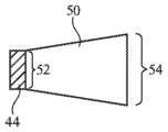
광원(14A)에 대한 일부 배열들에서, 비교적 작은 치수들을 갖는 발광 다이오드들(예컨대, 10 마이크로미터 미만의 측방향 치수들을 갖는 마이크로 발광 다이오드들 또는 빅셀들)이 요소들(44)을 형성하는 데 사용될 수 있다. 발광 요소들(발광 다이오드들 또는 레이저들)의 측방향 치수들이 10 마이크로미터 초과, 10 내지 200 마이크로미터, 적어도 40 마이크로미터, 500 마이크로미터 미만, 또는 다른 적합한 크기들인 구성들이 또한 사용될 수 있다. 원하는 경우, 발광 요소들(44)에는 도 9의 테이퍼형(tapered) 터널(50)과 같은 선택적 테이퍼형 터널들이 제공될 수 있다. 예를 들어, 발광 디바이스들(44)의 대응하는 2차원 어레이와 정합하는 2차원 터널 어레이의 일부일 수 있는 각각의 터널은 투명 중합체(clear polymer) 또는 다른 투명 재료로 형성될 수 있고, 각각의 발광 요소(44)의 방출된 광 영역의 크기를 (예컨대, 테이퍼형 터널(50)의 입력에서의 도 9의 더 작은 영역(52)으로부터 테이퍼형 터널(50)의 출력 표면에서의 확대된 영역(54)으로) 확장할 수 있다.In some arrangements for
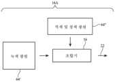
원하는 경우, 파장 선택적 광학 조합기가 상이한 파장들의 조명(22)을 병합하는 데 사용될 수 있다. 일례로서, 도 10의 예시적인 다파장 광원(14A)을 고려한다. 도 10에 도시된 바와 같이, 광원(14A)은 제1 세트의 발광 요소들(44')(예컨대, 녹색 발광 요소들(44)) 및 제2 세트의 발광 요소들(44")(예컨대, 적색 및 청색 발광 요소들(44)의 세트들)을 포함할 수 있다. 조합기(56)는 광원(44')으로부터의 녹색 광 및 광원(44")으로부터의 적색 및 청색 광을 조합하여 적색, 녹색 및 청색 조명(22)을 생성할 수 있다. 조합기(56)는 웨지 이색성 조합기(예컨대, 광원(44")을 향하는 기판의 제1 표면 상에 적색 광 반사 및 녹색 광 통과(red-light-reflecting-and-green-light-passing)의 이색성 코팅을 포함하고, 기판의 제2 반대편 표면 상에 청색 광 반사 및 녹색 광 통과(blue-light-reflecting-and-green-light passing)의 이색성 코팅을 포함하는 웨지형 기판)에 기초할 수 있다. 웨지 이색성 조합기는 공간 광 변조기(14C)를 향해 적색 및 청색 광을 반사시킬 것이고, 녹색 광이 공간 광 변조기(14C)를 향해 통과할 수 있게 할 것이다. 이러한 배열 또는 다른 파장 다중화 배열들(예컨대, 홀로그램들, 나노구조체들, 튜닝가능 격자들과 같은 튜닝가능 광학 컴포넌트들, 등에 기초한 파장 멀티플렉서들)은 광원들(44', 44")로부터 출력된 광을 조합하여, 조명(22)이 개별적으로 조정가능한 적색, 녹색 및 청색 광 컴포넌트들을 포함하도록 할 수 있다. 공간 광 변조기(14C)의 상이한 영역들이 상이한 요소들(44)로부터의 광에 의해 조명될 수 있다. 동작 동안, 개별 요소들(44)은 공간 광 변조기(14C) 상의 조명(22)의 공간 분포를 조정하도록 독립적으로 조정될 수 있다. 하나의 예시적인 구성에서, 광원(44")은 도 11에 도시된 바와 같이 적색 발광 요소들(44)의 3×3 어레이 및 청색 발광 요소들(44)의 3×3 어레이를 포함하고, 광원(44')은 도 12에 도시된 바와 같이 녹색 발광 요소들(44)의 3×3 어레이를 포함하며, 각각의 발광 요소(44)는 개별적으로 조정될 수 있다. 원하는 경우, 다른 수들의 요소들(44)이 광원(14A)에 포함될 수 있다.If desired, a wavelength selective optical combiner may be used to combine
도 13에 도시되는 광원(14A)의 예시적인 구성에서, 시준기 및 빔 조향 요소들(60)은 청색 요소(B), 녹색 요소들(G), 및 적색 요소들(R)과 같은 발광 요소들(44)로부터의 광을 스펙트럼 및 각도 조합기 요소들(62)로 선택적으로 라우팅하는 데 사용된다. 스펙트럼 및 각도 조합기 요소들은 대응하는 적색, 녹색, 및 청색 요소들(44)로부터의 적색, 녹색, 및 청색 광을 조명(22)의 일부분으로 조합한다. 요소들(60 및/또는 62)은, 다중화된 체적 홀로그램들, 스위칭가능 브래그 격자들(예컨대, 전기적으로 조정가능한 액정 격자들), 및 메타재료 요소들(예컨대, 각각의 요소가 그 요소의 기판을 통과하는 광에 대한 파장 멀티플렉서로서 기능하게 하도록 구성되는 높이들 및 다른 속성들을 갖는 투명 기판 상의 투명 재료의 나노필러들의 어레이로부터 각각 형성된 나노구조체 요소들)로부터 형성될 수 있다. 도 13에 도시된 바와 같이, 요소들(44)의 제1 세트(44A)는 공간 광 변조기(14C)의 제1 영역(46-3)에 조명(22)을 제공하도록 구성될 수 있고, 요소들(44)의 제2 세트(44B)는 공간 광 변조기(14C)의 제2 영역(46-2)에 조명(22)을 제공하도록 구성될 수 있고, 요소들(44)의 제3 세트(44C)는 공간 광 변조기(14C)의 제3 광 영역(46-1)에 조명(22)을 제공하도록 구성될 수 있다. 요소들(44)은 1차원 어레이로 배열될 수 있거나(예컨대, 요소들(44)은 모두 도 13의 페이지 내에 놓일 수 있음), 또는 2차원 어레이로 형성될 수 있다.In the exemplary configuration of
디스플레이 시스템(14)에 대한 다른 예시적인 배열이 도 14 및 도 15에 도시되어 있다. 이러한 예시적인 구성에서, 발광 요소 세트(44R)는 (예컨대, 3×3 어레이로) 적색 광을 생성하는 9개의 요소들(44)을 포함하고, 발광 요소 세트(44G)는 (예컨대, 3×3 어레이로) 녹색 광을 생성하는 9개의 요소들(44)을 포함하고, 발광 세트(44B)는 (예컨대, 3×3 어레이로) 3개의 청색 발광 요소들(44)을 포함한다. 일례로서, 세트들의 3×3 어레이 내에 9개 세트들의 요소들(44)이 있을 수 있다(세트들의 하나의 컬럼만이 도 14에 도시되어 있음). 광학 시스템(14B)은 플라이 아이 렌즈 어레이(66) 및 릴레이 렌즈(relay lens)(68)(예컨대, 둘 이상의 렌즈 요소들로부터 형성된 릴레이 렌즈 또는 다른 적합한 릴레이 렌즈)를 포함할 수 있다.Another exemplary arrangement for
도 15에 도시된 바와 같이, 렌즈 어레이(66)는, 각각의 발광 요소(44)로부터 방출된 광을 각각 수용하고 균질화하고 그 광을 릴레이 렌즈(68)에 제공하는 렌즈들(66E)과 같은 마이크로렌즈들을 포함할 수 있다. 요소들(44)은 1차원 어레이 또는 2차원 어레이로 조직화될 수 있다. 광학 시스템(14B)은, 요소들(44)이 광을 공간 광 변조기(14C)의 상이한 영역들에 제공하도록 구성될 수 있다. 예를 들어, 도 15의 세트(14R)의 3개의 적색 요소들(R) 각각은 공간 광 변조기(14C) 상의 3개의 각각의 영역들(70) 내의 광(22)을 개별적으로 제어하도록 개별적으로 조정될 수 있다.As shown in FIG. 15 ,
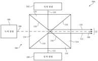
도 16은 상이한 파장들의 조명(22)을 병합하는 데 사용될 수 있는 다른 예시적인 광학 조합기의 도면이다. 도 16에 도시된 바와 같이, 광원(14A)은 녹색 광원(100), 적색 광원(102), 및 청색 광원(104)을 포함할 수 있다. 녹색 광원(100)은 녹색 발광 요소들(44)의 MxN 또는 NxN 어레이일 수 있다. 적색 광원(102)은 적색 발광 요소들(44)의 MxN 또는 NxN 어레이일 수 있다. 청색 광원(104)은 청색 발광 요소들(44)의 MxN 또는 NxN 어레이일 수 있다. 광원들(100, 102, 104)은 단지 몇몇 예들로서, 발광 요소들(44)의 7×7 어레이들, 1×1 어레이들, 또는 3×3 어레이들일 수 있다.16 is a diagram of another exemplary optical combiner that may be used to merge
광원(14A)은 광학 조합기(106)(예컨대, 도 10의 광학 조합기(56)와 같은 광학 조합기)를 포함할 수 있다. 광학 조합기(106)는 적색 광 반사 및 녹색 광 통과의 이색성 코팅(116)과, 청색 광 반사 및 녹색 광 통과의 이색성 코팅(118)을 포함할 수 있다. 코팅들(116, 118)은 웨지형 기판(114)의 표면들 상에 형성될 수 있다. 광학 조합기(106)는 적색 광원(102)으로부터의 적색 광(110)을 반사할 것이고, 청색 광원(104)으로부터의 청색 광(112)을 반사할 것이고, 녹색 광원(100)으로부터의 녹색 광(108)이 공간 광 변조기(예컨대, 도 1 내지 도 4 및 도 13 내지 도15의 공간 광 변조기(14C))를 향해 조명(22)으로서 통과하도록 할 것이다. 이러한 방식으로 구성될 때, 광(110, 108, 112)은 공간 광 변조기에 제공될 때 동축으로 정렬될 수 있다.
도 16의 예에서, 광학 조합기(106)는 4개의 웨지형 기판(114)을 포함한다. 이는 단지 예시적인 것이며, 대체적으로, 광학 조합기(106)는 임의의 원하는 수의 웨지형 기판(114)을 포함할 수 있거나, 또는 다른 형상들의 기판들을 포함할 수 있다. 광원들(100, 102, 104)은 임의의 원하는 파장들의 광을 방출할 수 있다(예컨대, 코팅(116)은 광원(100)으로부터의 광을 통과시키면서 광원(102)으로부터의 광을 반사시키는 반면, 코팅(118)은 광원(100)으로부터의 광을 통과시키면서 광원(104)으로부터의 광을 반사시킴). 원하는 경우, 광원들(100, 102, 104)과 광학 조합기(106) 사이에는 렌즈들과 같은 선택적 시준 광학기기가 개재될 수 있다. 다른 적합한 배열에서, 광학 조합기(106)는 도 17의 예에 도시된 바와 같이, 웨지형 기판들 없이 형성될 수 있다. 도 17에 도시된 바와 같이, 광학 조합기(106)는 적색 광 반사 및 녹색 광 통과의 플레이트(122)와, 청색 광 반사 및 녹색 광 통과의 이색성 플레이트(120)를 포함할 수 있다. 플레이트들(120, 122)은, 예를 들어, 유리 기판들 또는 이색성 코팅들이 제공되어 있는 다른 실질적으로 평면의 기판들을 포함할 수 있다.In the example of FIG. 16 ,
마이크로렌즈들(66E)이 렌즈 어레이(66)에 제공되는 도 15의 예는 단지 예시적인 것이다. 다른 적합한 배열에서, 각각의 발광 요소(44)에는 도 18에 도시된 바와 같이, 각각의 마이크로렌즈들이 제공될 수 있다. 도 18에 도시된 바와 같이, 광원(14A) 내의 발광 요소들(44)은 비교적 작아서, 요소들(44)이 갭들(130)에 의해 분리되게 할 수 있다. 각각의 마이크로렌즈(132)가 각각의 요소(44) 위에 제공될 수 있다. 각각의 마이크로렌즈(132)는 인접한 마이크로렌즈들(132)이 요소들(44) 사이의 갭들(130)을 브리지(bridge)하도록, 아래에 놓인 요소(44)보다 훨씬 더 넓은 폭(134)을 가질 수 있다. 이는, 마이크로렌즈들(132)의 부재 하에서 달리 제공되는 것보다, 각각의 요소(44)로부터의 광이 더 큰 영역(예컨대, 마이크로렌즈들(132)에 의해 제공되는 영역)에 걸쳐 방출되는 것처럼 보이도록 할 수 있다.The example of FIG. 15 in which microlenses 66E are provided in
원하는 경우, 광원(14A) 내의 발광 요소들(44)의 세기는 광학기기(예컨대, 광학 시스템(14B) 내의 광학기기)와 연관된 주변 픽셀들로부터의 광에 대한 세기 및/또는 왜곡에서의 내재적인 축외 롤 오프(off-axis roll off)를 보상하도록 독립적으로 제어될 수 있다. 도 19는 발광 요소들(44)의 세기가 이들 효과들을 완화시키도록 독립적으로 제어될 수 있는 방법을 도시하는 도면이다.If desired, the intensity of
도 19에 도시된 바와 같이, 수평축은 광원(14A)의 횡축을 따르는 픽셀 포지션(예컨대, 도 4 내지 도 18과 관련되어 전술된 바와 같이, M × N 또는 N × N 발광 요소들(44)의 어레이를 가로지르는 수평 또는 수직 픽셀 포지션)을 예시한다. 도 19의 곡선(156)은 광원(14A)에 의해 생성된 조명(22)의 세기를 예시한다. 곡선(150)은 광원(14A)에 의해 생성될 수 있는 최대 세기를 예시한다. 곡선(156)에 의해 도시된 바와 같이, 조명(22)은 (예컨대, 어레이의 주변에서의 픽셀들에 대해) 중심축(C)에서의 피크 세기로부터 중심축(C)에서 벗어난 픽셀 포지션들에서의 최소 세기로의 롤 오프를 나타낼 수 있다. 이러한 세기의 변동은, 예를 들어, 광원(14A) 및/또는 광학 시스템(14B)과 연관된 세기의 내재적인 축외 롤 오프 및/또는 광학 시스템(14B) 내의 렌즈 요소들(예컨대, 가변 배율을 픽셀 포지션의 함수로서 제공하는 렌즈 요소들)에 의해 생성된 주변 픽셀들로부터의 광에 대한 축외 왜곡에 의해 생성될 수 있다.As shown in FIG. 19, the horizontal axis is the pixel position along the abscissa axis of
이러한 변동을 완화시키기 위해, 중심축(C)을 벗어나 (예컨대, 어레이의 주변부에) 위치된 발광 요소들(44)은 화살표들(154)에 의해 도시된 바와 같이, 증가된 세기를 갖는 광을 방출하도록 독립적으로 제어될 수 있다. 주변 픽셀 세기에서의 이러한 부스트는, 광이 광학 시스템(14B)을 통과할 때까지 각각의 픽셀 포지션에 대해 균일한 세기를 갖는 조명(22)을 제공할 수 있다. 다른 적합한 배열에서, 중심축(C)에 위치된 발광 요소들(44)은 화살표(158)에 의해 도시된 바와 같이, 감소된 세기를 갖는(예컨대, 최저 세기 픽셀들의 세기와 일치하는 세기를 갖는) 광을 방출하도록 독립적으로 제어될 수 있다. 중심 픽셀 세기에서의 이러한 감소는, 광이 광학 시스템(14B)을 통과할 때까지 각각의 픽셀 포지션에 대해 균일한 세기를 갖는 조명(22)을 제공할 수 있다. 이러한 세기의 조정들은 각각의 발광 요소(44)에 제공되는 전류를 조정함으로써, 각각의 발광 요소(44)를 제어하는 데 사용되는 펄스 폭 변조를 조정함으로써, 등등으로써 제공될 수 있다. 어레이 내의 각각의 발광 요소(44)의 세기를 픽셀 포지션의 함수로서 독립적으로 제어함으로써, 광학 시스템(14B)에 의해 도입된 왜곡들에도 불구하고 균일한 세기의 광이 제공될 수 있다. 다른 적합한 배열에서, 균일한 세기로 조명(22)을 제공하기 위해 이러한 픽셀별 세기 조정들 대신에 또는 그에 더하여 사전 왜곡 기법들이 사용될 수 있다. 도 19의 예는 단지 예시적인 것이다. 곡선들(150, 156 및 152)은 다른 형상들을 가질 수 있다.To mitigate these fluctuations,
일 실시예에 따르면, 머리 장착형 지지 구조체, 제어 회로부, 머리 장착형 지지 회로부에 의해 지지되는 공간 광 변조기 - 공간 광 변조기는 픽셀들을 갖고, 제어 회로부는 픽셀들을 사용하여 이미지를 생성하도록 구성됨 -, 조명을 생성하도록 구성된 다수의 발광 요소들을 갖는 광원, 및 조명을 공간 광 변조기로 지향시키도록 그리고 공간 광 변조기로부터의 대응하는 반사된 이미지 광을 아이 박스로 지향시키도록 구성된 광학 시스템을 포함하는 전자 디바이스가 제공되고, 제어 회로부는 공간 광 변조기의 상이한 각각의 영역들에서 조명을 독립적으로 조정하기 위해 발광 요소들 각각을 독립적으로 조정하도록 구성된다.According to one embodiment, a head mounted support structure, control circuitry, a spatial light modulator supported by the head mounted support circuitry, wherein the spatial light modulator has pixels, and the control circuitry is configured to use the pixels to generate an image; An electronic device comprising a light source having a plurality of light emitting elements configured to generate, and an optical system configured to direct illumination to a spatial light modulator and to direct corresponding reflected image light from the spatial light modulator to an eye box. and the control circuitry is configured to independently adjust each of the light emitting elements to independently adjust illumination in different respective regions of the spatial light modulator.
다른 실시예에 따르면, 다수의 발광 요소들은 발광 요소들의 1차원 어레이를 형성하도록 구성된다.According to another embodiment, multiple light emitting elements are configured to form a one-dimensional array of light emitting elements.
다른 실시예에 따르면, 다수의 발광 요소들은 발광 요소들의 세트들의 어레이를 형성하도록 구성된다.According to another embodiment, multiple light emitting elements are configured to form an array of sets of light emitting elements.
다른 실시예에 따르면, 발광 요소들의 각각의 세트는 발광 요소들 중 적어도 2개의 발광요소들을 포함한다.According to another embodiment, each set of light emitting elements includes at least two of the light emitting elements.
다른 실시예에 따르면, 발광 요소들의 각각의 세트는 발광 요소들의 2차원 어레이를 포함한다.According to another embodiment, each set of light emitting elements includes a two-dimensional array of light emitting elements.
다른 실시예에 따르면, 발광 요소들의 세트들의 어레이는 세트들의 2차원 어레이를 형성하도록 구성된다.According to another embodiment, the array of sets of light emitting elements is configured to form a two-dimensional array of sets.
다른 실시예에 따르면, 발광 요소들은 제어 회로부에 의해 독립적으로 조정되도록 구성된 다수의 적색 발광 다이오드들, 제어 회로부에 의해 독립적으로 조정되도록 구성된 다수의 녹색 발광 다이오드들, 및 제어 회로부에 의해 독립적으로 조정되도록 구성된 다수의 청색 발광 다이오드들을 포함하고, 광학 시스템은 플라이 아이 렌즈 어레이, 및 플라이 아이 렌즈 어레이와 공간 광 변조기 사이에 개재된 릴레이 렌즈를 포함한다.According to another embodiment, the light emitting elements are a plurality of red light emitting diodes configured to be independently regulated by control circuitry, a plurality of green light emitting diodes configured to be independently regulated by control circuitry, and a plurality of green light emitting diodes configured to be independently regulated by control circuitry. A plurality of blue light emitting diodes are configured, and the optical system includes a fly-eye lens array and a relay lens interposed between the fly-eye lens array and the spatial light modulator.
다른 실시예에 따르면, 광학 시스템은 시준 렌즈, 확산기, 및 집광 렌즈를 포함하고, 광원과 공간 광 변조기 사이에는 플라이 아이 렌즈 어레이가 존재하지 않는다.According to another embodiment, the optical system includes a collimating lens, a diffuser, and a condensing lens, and there is no fly-eye lens array between the light source and the spatial light modulator.
다른 실시예에 따르면, 발광 요소들은 적색 발광 다이오드들, 녹색 발광 다이오드들, 및 청색 발광 다이오드들을 포함한다.According to another embodiment, the light emitting elements include red light emitting diodes, green light emitting diodes, and blue light emitting diodes.
다른 실시예에 따르면, 공간 광 변조기는 액정 온 실리콘 디바이스 및 디지털 마이크로미러 디바이스로 이루어진 그룹으로부터 선택된 공간 광 변조기를 포함한다.According to another embodiment, the spatial light modulator comprises a spatial light modulator selected from the group consisting of a liquid crystal on silicon device and a digital micromirror device.
또 다른 실시예에 따르면, 발광 요소들은 발광 다이오드들을 포함한다.According to another embodiment, the light emitting elements include light emitting diodes.
또 다른 실시예에 따르면, 발광 요소들은 레이저들을 포함한다.According to another embodiment, the light emitting elements include lasers.
다른 실시예에 따르면, 발광 요소들은 적어도 3개의 적색 발광 다이오드들, 적어도 3개의 녹색 발광 다이오드들, 및 적어도 3개의 청색 발광 다이오드들을 포함한다.According to another embodiment, the light emitting elements include at least three red light emitting diodes, at least three green light emitting diodes, and at least three blue light emitting diodes.
다른 실시예에 따르면, 광원은 적색 발광 다이오드들로부터의 적색 광, 청색 발광 다이오드들로부터의 청색 광, 및 녹색 발광 다이오드들로부터의 녹색 광을 조합하여 조명을 형성하도록 구성된 이색성 웨지 조합기를 포함한다.According to another embodiment, the light source includes a dichroic wedge combiner configured to combine red light from red light emitting diodes, blue light from blue light emitting diodes, and green light from green light emitting diodes to form illumination. .
다른 실시예에 따르면, 발광 요소들은 적색, 녹색, 및 청색 발광 다이오드들을 포함하고, 광원은 스펙트럼 및 각도 조합기 요소, 적색 발광 다이오드로부터 스펙트럼 및 각도 조합기 요소로 적색 광을 라우팅하도록 구성된 적색 시준기 및 빔 조향 요소, 녹색 발광 다이오드로부터 스펙트럼 및 각도 조합기 요소로 녹색 광을 라우팅하도록 구성된 녹색 시준기 및 빔 조향 요소, 및 청색 발광 다이오드로부터 스펙트럼 및 각도 조합기 요소로 청색 광을 라우팅하도록 구성된 청색 시준기 및 빔 조향 요소를 포함한다.According to another embodiment, the light emitting elements include red, green, and blue light emitting diodes, the light source is a spectral and angle combiner element, a red collimator configured to route red light from the red light emitting diodes to the spectral and angle combiner element, and beam steering. element, a green collimator and beam steering element configured to route green light from the green light emitting diode to the spectral and angle combiner element, and a blue collimator and beam steering element configured to route blue light from the blue light emitting diode to the spectral and angle combiner element. do.
다른 실시예에 따르면, 스펙트럼 및 각도 조합기 요소는 적색, 녹색 및 청색 광을 조합하여 공간 광 변조기의 제2 영역을 조명하지 않고서 공간 광 변조기의 제1 영역을 조명하는 조명의 일부분을 생성하도록 구성된다.According to another embodiment, the spectral and angle combiner element is configured to combine red, green and blue light to create a portion of illumination that illuminates a first region of the spatial light modulator without illuminating a second region of the spatial light modulator. .
일 실시예에 따르면, 공간 광 변조기, 조명을 생성하도록 구성된 광원, 및 조명을 공간 광 변조기로 지향시키도록 그리고 공간 광 변조기로부터의 대응하는 반사된 이미지 광을 아이 박스로 지향시키도록 구성된 광학 시스템을 포함하는 디스플레이 시스템 - 광원은 다수의 적색 발광 다이오드들, 다수의 녹색 발광 다이오드들, 및 다수의 청색 발광 다이오드들을 포함함 -, 및 적색 발광 다이오드들 각각을 독립적으로 조정하도록, 녹색 발광 다이오드들 각각을 독립적으로 조정하도록, 그리고 청색 발광 다이오드들 각각을 독립적으로 조정하도록 구성된 제어 회로부를 포함하는 머리 장착형 디바이스가 제공된다.According to one embodiment, a spatial light modulator, a light source configured to generate illumination, and an optical system configured to direct illumination to the spatial light modulator and to direct corresponding reflected image light from the spatial light modulator to an eye box are provided. A display system comprising a light source comprising a plurality of red light emitting diodes, a plurality of green light emitting diodes, and a plurality of blue light emitting diodes, and each of the green light emitting diodes to independently adjust each of the red light emitting diodes. A head mounted device is provided that includes control circuitry configured to independently adjust and to independently adjust each of the blue light emitting diodes.
다른 실시예에 따르면, 광원은 적색, 녹색 및 청색 광을 생성하고, 적색, 녹색 및 청색 광을 조합하여 조명을 제공하도록 구성된 광학 요소를 포함한다.According to another embodiment, the light source includes optical elements configured to generate red, green and blue light and provide illumination by combining the red, green and blue light.
다른 실시예에 따르면, 광학 요소는 홀로그램, 메타구조체, 및 스위칭가능 격자로 이루어진 그룹으로부터 선택된 광학 요소를 포함한다.According to another embodiment, the optical element includes an optical element selected from the group consisting of holograms, metastructures, and switchable gratings.
일 실시예에 따르면, 조명을 생성하도록 구성된 광원 - 광원은 다중요소 발광 디바이스들의 N x N 어레이를 갖고, N은 적어도 2이며, 각각의 다중요소 발광 디바이스는 적어도 3개의 발광 다이오드들을 가짐 -, 공간 광 변조기, 및 조명을 공간 광 변조기로 지향시키도록 그리고 공간 광 변조기로부터의 대응하는 반사된 이미지 광을 아이 박스로 지향시키도록 구성된 광학 시스템을 포함하는 디스플레이 시스템이 제공된다.According to one embodiment, a light source configured to generate illumination, wherein the light source has an N x N array of multi-component light emitting devices, where N is at least 2, each multi-component light emitting device having at least 3 light emitting diodes, space A display system is provided that includes a light modulator and an optical system configured to direct illumination to the spatial light modulator and to direct corresponding reflected image light from the spatial light modulator to the eye box.
전술한 것은 단지 예시적인 것이며 설명된 실시예들에 대해 다양한 수정들이 이루어질 수 있다. 전술한 실시예들은 개별적으로 또는 임의의 조합으로 구현될 수 있다.The foregoing is merely illustrative and various modifications may be made to the described embodiments. The foregoing embodiments may be implemented individually or in any combination.
Claims (20)
Translated fromKorean머리 장착형 지지 구조체;
제어 회로부;
상기 머리 장착형 지지 구조체에 의해 지지되는 공간 광 변조기 - 상기 공간 광 변조기는 픽셀들을 갖고 상기 제어 회로부는 상기 픽셀들을 사용하여 이미지를 생성하도록 구성됨 -;
조명을 생성하도록 구성된 다수의 발광 요소들을 갖는 광원; 및
상기 조명을 상기 공간 광 변조기로 지향시키도록 그리고 상기 공간 광 변조기로부터의 대응하는 반사된 이미지 광을 아이 박스(eye box)로 지향시키도록 구성된 광학 시스템 - 상기 제어 회로부는 상기 공간 광 변조기의 상이한 각각의 영역들에서 상기 조명을 독립적으로 조정하기 위해 상기 발광 요소들을 독립적으로 조정하도록 구성되고, 상기 제어 회로부는 상기 반사된 이미지 광의 시야의 미사용 부분에 대응하는 적어도 하나의 발광 요소를 디밍함으로써 상기 발광 요소들을 독립적으로 조정하도록 구성되고, 상기 광학 시스템은 상기 반사된 이미지 광을 재지향시키도록 구성된 적어도 하나의 렌즈를 포함하고, 상기 적어도 하나의 렌즈는 상기 반사된 이미지 광의 시야를 가로지르는 상기 반사된 이미지 광에 부여된 세기에서 축외 롤 오프(off-axis roll off)를 나타내고, 상기 제어 회로부는 상기 적어도 하나의 렌즈에 의해 생성된 세기에서 상기 축외 롤 오프를 보상하기 위해 상기 시야에 걸쳐 변화하는 세기 프로파일을 상기 조명에 제공하기 위해 상기 광원을 독립적으로 조정하도록 구성됨 - 을 포함하는, 전자 디바이스.As an electronic device,
a head-mounted support structure;
control circuitry;
a spatial light modulator supported by the head mounted support structure, the spatial light modulator having pixels and the control circuitry being configured to use the pixels to generate an image;
a light source having a plurality of light emitting elements configured to generate illumination; and
An optical system configured to direct the illumination to the spatial light modulator and to direct corresponding reflected image light from the spatial light modulator to an eye box, wherein the control circuitry is configured to direct each of the different spatial light modulators to an eye box. and the control circuitry is configured to independently adjust the light emitting elements to independently adjust the illumination in areas of the light emitting element by dimming the at least one light emitting element corresponding to an unused portion of the field of view of the reflected image light. and the optical system comprises at least one lens configured to redirect the reflected image light, the at least one lens configured to direct the reflected image light across a field of view of the reflected image light. Indicates an off-axis roll off at an intensity imparted to , wherein the control circuitry determines an intensity profile that varies across the field of view to compensate for the off-axis roll off at an intensity produced by the at least one lens. configured to independently adjust the light source to provide the illumination.
플라이 아이(fly's eye) 렌즈 어레이; 및
상기 플라이 아이 렌즈 어레이와 상기 공간 광 변조기 사이에 개재된 릴레이 렌즈(relay lens)를 포함하는, 전자 디바이스.2. The method of claim 1, wherein the light emitting elements are configured to be independently controlled by a plurality of red light emitting diodes configured to be independently controlled by the control circuitry, a plurality of green light emitting diodes configured to be independently controlled by the control circuitry, and configured to be independently controlled by the control circuitry. comprising a plurality of blue light emitting diodes configured to be independently adjusted, the optical system comprising:
a fly's eye lens array; and
and a relay lens interposed between the fly eye lens array and the spatial light modulator.
스펙트럼 및 각도 조합기 요소;
상기 적색 발광 다이오드로부터의 적색 광을 상기 스펙트럼 및 각도 조합기 요소로 라우팅하도록 구성된 적색 시준기 및 빔 조향 요소;
상기 녹색 발광 다이오드로부터의 녹색 광을 상기 스펙트럼 및 각도 조합기 요소로 라우팅하도록 구성된 녹색 시준기 및 빔 조향 요소; 및
상기 청색 발광 다이오드로부터의 청색 광을 상기 스펙트럼 및 각도 조합기 요소로 라우팅하도록 구성된 청색 시준기 및 빔 조향 요소를 포함하는, 전자 디바이스.The method of claim 1, wherein the light emitting elements include red, green and blue light emitting diodes, and the light source comprises:
spectral and angle combiner elements;
a red collimator and beam steering element configured to route red light from the red light emitting diode to the spectral and angle combiner element;
a green collimator and beam steering element configured to route green light from the green light emitting diode to the spectral and angle combiner element; and
and a blue collimator and beam steering element configured to route blue light from the blue light emitting diode to the spectral and angle combiner element.
공간 광 변조기, 조명을 생성하도록 구성된 광원, 및 상기 조명을 상기 공간 광 변조기로 지향시키도록 그리고 상기 공간 광 변조기로부터의 대응하는 반사된 이미지 광을 아이 박스로 지향시키도록 구성된 광학 시스템을 포함하는 디스플레이 시스템 - 상기 광원은 다수의 적색 발광 다이오드들, 다수의 녹색 발광 다이오드들, 및 다수의 청색 발광 다이오드들을 포함하고, 상기 광학 시스템은 상기 반사된 이미지 광을 재지향시키도록 구성된 적어도 하나의 렌즈를 포함하고, 상기 적어도 하나의 렌즈는 상기 반사된 이미지 광의 시야를 가로지르는 상기 반사된 이미지 광에 부여된 세기에서 축외 롤 오프(off-axis roll off)를 나타냄 -; 및
제어 회로부를 포함하고, 상기 제어 회로부는:
상기 공간 광 변조기의 제2 부분을 적색 광으로 조명하면서 상기 공간 광 변조기의 제1 영역에 대한 상기 조명의 적색 부분을 턴오프하도록 상기 적색 발광 다이오드들 각각을 독립적으로 조정하고 - 상기 공간 광 변조기의 상기 제1 영역은 상기 반사된 이미지 광의 시야의 미사용 부분에 대응함 -;
상기 녹색 발광 다이오드들 각각을 독립적으로 조정하고;
상기 청색 발광 다이오드들 각각을 독립적으로 조정하고;
상기 적어도 하나의 렌즈에 의해 생성된 세기에서 상기 축외 롤 오프를 보상하는 방식으로 상기 시야에 걸쳐 변화하는 세기 프로파일을 상기 조명에 제공하기 위해 상기 적색, 청색 및 녹색 발광 다이오드들 중 하나 이상을 독립적으로 조정하도록 구성되는, 머리 장착형 디바이스.As a head-mounted device,
A display comprising a spatial light modulator, a light source configured to generate illumination, and an optical system configured to direct the illumination to the spatial light modulator and to direct corresponding reflected image light from the spatial light modulator to an eye box. system - the light source comprises a plurality of red light emitting diodes, a plurality of green light emitting diodes, and a plurality of blue light emitting diodes, the optical system comprising at least one lens configured to redirect the reflected image light; , the at least one lens exhibits an off-axis roll off in intensity imparted to the reflected image light across the field of view of the reflected image light; and
comprising control circuitry, wherein the control circuitry comprises:
independently adjusting each of the red light emitting diodes to turn off a red portion of the illumination for a first region of the spatial light modulator while illuminating a second portion of the spatial light modulator with red light; the first region corresponds to an unused portion of the field of view of the reflected image light;
independently adjust each of the green light emitting diodes;
independently adjusting each of the blue light emitting diodes;
independently one or more of the red, blue, and green light emitting diodes to provide the illumination with an intensity profile that varies across the field of view in a manner that compensates for the off-axis roll-off in the intensity produced by the at least one lens. A head-mounted device configured to adjust.
조명을 생성하도록 구성된 광원 - 상기 광원은 다중요소 발광 디바이스들의 어레이를 갖고, 각각의 다중요소 발광 디바이스는 적어도 3개의 발광 다이오드들을 가짐 -;
공간 광 변조기;
상기 조명을 상기 공간 광 변조기로 지향시키도록 그리고 상기 공간 광 변조기로부터의 대응하는 반사된 이미지 광을 아이 박스로 지향시키도록 구성된 광학 시스템;
상기 반사된 이미지 광을 지향시키도록 구성되고 상기 반사된 이미지 광의 시야를 가로지르는 상기 반사된 이미지 광에 부여된 세기에서 축외 롤 오프(off-axis roll off)를 나타내는 적어도 하나의 렌즈; 및
상기 적어도 하나의 렌즈에 의해 생성된 세기에서 상기 축외 롤 오프를 보상하기 위해 상기 시야에 걸쳐 변화하는 세기 프로파일을 상기 조명에 제공하기 위해 상기 다중요소 발광 디바이스들의 어레이를 독립적으로 조정하도록 구성된 제어 회로부를 포함하는, 디스플레이 시스템.As a display system,
a light source configured to produce illumination, the light source having an array of multi-component light emitting devices, each multi-component light emitting device having at least three light emitting diodes;
spatial light modulator;
an optical system configured to direct the illumination to the spatial light modulator and to direct corresponding reflected image light from the spatial light modulator to an eye box;
at least one lens configured to direct the reflected image light and exhibit an off-axis roll off in an intensity imparted to the reflected image light across the field of view of the reflected image light; and
control circuitry configured to independently adjust the array of multi-element light emitting devices to provide the illumination with a varying intensity profile across the field of view to compensate for the off-axis roll-off in the intensity produced by the at least one lens; Including, the display system.
Applications Claiming Priority (5)
| Application Number | Priority Date | Filing Date | Title |
|---|---|---|---|
| US201862691513P | 2018-06-28 | 2018-06-28 | |
| US62/691,513 | 2018-06-28 | ||
| US16/409,681 | 2019-05-10 | ||
| US16/409,681US12111467B2 (en) | 2018-06-28 | 2019-05-10 | Electronic device with multi-element display illumination system |
| PCT/US2019/036168WO2020005507A1 (en) | 2018-06-28 | 2019-06-07 | Electronic device with multi-element display illumination system |
Publications (2)
| Publication Number | Publication Date |
|---|---|
| KR20210002614A KR20210002614A (en) | 2021-01-08 |
| KR102549949B1true KR102549949B1 (en) | 2023-06-29 |
Family
ID=67003762
Family Applications (1)
| Application Number | Title | Priority Date | Filing Date |
|---|---|---|---|
| KR1020207033661AActiveKR102549949B1 (en) | 2018-06-28 | 2019-06-07 | Electronic device with multi-element display lighting system |
Country Status (6)
| Country | Link |
|---|---|
| US (1) | US12111467B2 (en) |
| EP (1) | EP3781980A1 (en) |
| JP (1) | JP7204783B2 (en) |
| KR (1) | KR102549949B1 (en) |
| CN (1) | CN110658629B (en) |
| WO (1) | WO2020005507A1 (en) |
Families Citing this family (9)
| Publication number | Priority date | Publication date | Assignee | Title |
|---|---|---|---|---|
| US11450297B1 (en)* | 2018-08-30 | 2022-09-20 | Apple Inc. | Electronic device with central and peripheral displays |
| WO2020235816A1 (en)* | 2019-05-21 | 2020-11-26 | Samsung Electronics Co., Ltd. | Glasses-type display apparatus |
| CN112051670A (en)* | 2019-06-05 | 2020-12-08 | 苹果公司 | Electronic device with multi-element display illumination system |
| US11852816B1 (en) | 2020-07-13 | 2023-12-26 | Apple Inc. | Optical systems with resolution-enhancing spectral shifting |
| US12105287B1 (en) | 2020-07-13 | 2024-10-01 | Apple Inc. | Optical systems for leveraging the non-zero transition time of display panel mirrors |
| JP2024526684A (en)* | 2021-07-12 | 2024-07-19 | アップル インコーポレイテッド | System with adjustable lights |
| US11775021B2 (en)* | 2021-08-17 | 2023-10-03 | Apple Inc. | Moisture-insensitive optical touch sensors |
| WO2024129738A1 (en)* | 2022-12-16 | 2024-06-20 | Lumileds Llc | Light-emitting device with multiple metastructured optical elements |
| EP4575591A1 (en)* | 2023-12-22 | 2025-06-25 | Imec VZW | An optical metamaterial-based color combiner |
Citations (2)
| Publication number | Priority date | Publication date | Assignee | Title |
|---|---|---|---|---|
| US20130208362A1 (en)* | 2012-02-15 | 2013-08-15 | David D. Bohn | Laser illumination scanning |
| CN105334687A (en)* | 2014-08-01 | 2016-02-17 | 欧司朗股份有限公司 | Projection system |
Family Cites Families (61)
| Publication number | Priority date | Publication date | Assignee | Title |
|---|---|---|---|---|
| US4058753A (en)* | 1974-08-02 | 1977-11-15 | Zenith Radio Corporation | Electron gun having an extended field beam focusing and converging lens |
| US5504514A (en) | 1992-02-13 | 1996-04-02 | Texas Instruments Incorporated | System and method for solid state illumination for spatial light modulators |
| EP0742940A4 (en) | 1994-01-31 | 1998-09-30 | Sdl Inc | Laser illuminated display system |
| JPH08202292A (en) | 1995-01-25 | 1996-08-09 | Sony Corp | Image display device |
| JP2007065677A (en) | 1997-03-24 | 2007-03-15 | Sony Corp | Picture display apparatus |
| JPH10269802A (en) | 1997-03-24 | 1998-10-09 | Sony Corp | Lighting system and image display unit |
| US6079833A (en) | 1999-02-17 | 2000-06-27 | Hughes-Jvc Technology Corporation | Laser imaging using a spatial light modulator |
| CN1298175C (en) | 2001-07-06 | 2007-01-31 | 以克斯普雷有限公司 | Image projecting device and method |
| KR100403599B1 (en) | 2001-11-06 | 2003-10-30 | 삼성전자주식회사 | Illumination system and a projection system imploying it |
| JP4348457B2 (en) | 2002-03-13 | 2009-10-21 | ドルビー ラボラトリーズ ライセンシング コーポレイション | High dynamic range display, display controller, and image display method |
| JP3866651B2 (en) | 2002-12-02 | 2007-01-10 | Necビューテクノロジー株式会社 | Projection display |
| JP2005012303A (en) | 2003-06-17 | 2005-01-13 | Nikon Corp | Color separation optical system and projection display device |
| JP4068551B2 (en) | 2003-11-21 | 2008-03-26 | Necディスプレイソリューションズ株式会社 | LIGHT SOURCE DEVICE AND ITS DRIVE METHOD AND VIDEO DISPLAY DEVICE |
| KR100636179B1 (en)* | 2004-09-24 | 2006-10-19 | 삼성전자주식회사 | Lighting unit employing LED and image projector using the same |
| US20060066557A1 (en) | 2004-09-27 | 2006-03-30 | Floyd Philip D | Method and device for reflective display with time sequential color illumination |
| EP1834320B1 (en) | 2004-12-23 | 2017-08-30 | Dolby Laboratories Licensing Corporation | Wide color gamut displays |
| US20070177275A1 (en) | 2006-01-04 | 2007-08-02 | Optical Research Associates | Personal Display Using an Off-Axis Illuminator |
| US8585207B1 (en) | 2006-06-07 | 2013-11-19 | University of Central Florida Research Research Foundation, Inc. | Up converters and GaAs based semiconductor light source system for large color gamut display and projection displays |
| US8520290B2 (en) | 2007-08-16 | 2013-08-27 | Silicon Quest Kabushiki Kaisha | Display system for higher grayscale with a varying light source |
| DE102007053481B4 (en) | 2007-11-09 | 2020-01-02 | Diehl Aerospace Gmbh | Method for dimming light sources designed to generate mixed light colors |
| US7909474B2 (en) | 2007-12-05 | 2011-03-22 | Eastman Kodak Company | Display apparatus using bilinear electromechanical modulator |
| EP2085961A1 (en)* | 2008-01-30 | 2009-08-05 | Koninklijke Philips Electronics N.V. | Control of a display |
| JP2009211819A (en) | 2008-02-29 | 2009-09-17 | Effect Meiji:Kk | Lighting device for display use |
| US20100149073A1 (en) | 2008-11-02 | 2010-06-17 | David Chaum | Near to Eye Display System and Appliance |
| JP5402293B2 (en) | 2009-06-22 | 2014-01-29 | ソニー株式会社 | Head-mounted display and image display method in head-mounted display |
| CN101989033A (en) | 2009-07-31 | 2011-03-23 | 华柏光电股份有限公司 | Illuminating system for miniaturized projector |
| WO2011025724A1 (en) | 2009-08-27 | 2011-03-03 | Dolby Laboratories Licensing Corporation | Optical mixing and shaping system for display backlights and displays incorporating the same |
| US8860751B2 (en) | 2009-09-01 | 2014-10-14 | Entertainment Experience Llc | Method for producing a color image and imaging device employing same |
| US8964298B2 (en) | 2010-02-28 | 2015-02-24 | Microsoft Corporation | Video display modification based on sensor input for a see-through near-to-eye display |
| CN101881936B (en) | 2010-06-04 | 2013-12-25 | 江苏慧光电子科技有限公司 | Holographical wave guide display and generation method of holographical image thereof |
| US8444275B2 (en) | 2010-08-12 | 2013-05-21 | Eastman Kodak Company | Light source control for projector with multiple pulse-width modulated light sources |
| CN103430553B (en) | 2011-03-14 | 2016-08-31 | 杜比实验室特许公司 | Display device and method for generating images |
| CN102542927B (en) | 2012-01-06 | 2015-04-08 | 广东威创视讯科技股份有限公司 | Device for removing display pixel particle effect and OLED (organic light emitting diode) display screen |
| JP6008086B2 (en) | 2012-03-26 | 2016-10-19 | セイコーエプソン株式会社 | Head-mounted display device |
| GB201304659D0 (en) | 2013-03-14 | 2013-05-01 | Sec Dep For Business Innovation & Skills The | Display and method of operating a display |
| WO2014155288A2 (en) | 2013-03-25 | 2014-10-02 | Ecole Polytechnique Federale De Lausanne (Epfl) | Method and apparatus for head worn display with multiple exit pupils |
| CN203224665U (en) | 2013-04-17 | 2013-10-02 | 宁波舜宇仪器有限公司 | LED fluorescence lighting device |
| CN103578367A (en) | 2013-11-13 | 2014-02-12 | 广东威创视讯科技股份有限公司 | LED display device |
| DE102014003351B4 (en) | 2014-03-07 | 2022-11-03 | Dioptic Gmbh | Head-up display and display method |
| US10746994B2 (en) | 2014-08-07 | 2020-08-18 | Microsoft Technology Licensing, Llc | Spherical mirror having a decoupled aspheric |
| US9494794B2 (en)* | 2014-09-02 | 2016-11-15 | Ostendo Technologies, Inc. | Split exit pupil heads-up display systems and methods |
| TWI531215B (en) | 2014-09-10 | 2016-04-21 | 台達電子工業股份有限公司 | Coded illuminator and light field projection device using the same |
| EP3226799A4 (en) | 2014-12-05 | 2018-07-25 | Camplex, Inc. | Surgical visualization systems and displays |
| CN105988266A (en) | 2015-02-05 | 2016-10-05 | 深圳市绎立锐光科技开发有限公司 | Projection equipment, projection control system and projection control method |
| KR102580771B1 (en) | 2015-05-04 | 2023-09-19 | 매직 립, 인코포레이티드 | Separated pupil optical systems for virtual and augmented reality and methods for displaying images using the same |
| US10094530B2 (en) | 2015-06-25 | 2018-10-09 | Texas Instruments Incorporated | Apparatus for spatially and spectrally adaptable dichromatic white light source using spatial light modulator |
| US20170285343A1 (en) | 2015-07-13 | 2017-10-05 | Mikhail Belenkii | Head worn display with foveal and retinal display |
| KR102069024B1 (en) | 2015-09-03 | 2020-01-22 | 쓰리엠 이노베이티브 프로퍼티즈 컴파니 | Optical system |
| JP6779984B2 (en) | 2015-09-05 | 2020-11-04 | レイア、インコーポレイテッドLeia Inc. | Condensing backlight and near-eye display system using it |
| US20180284441A1 (en) | 2015-10-08 | 2018-10-04 | Corning Incorporated | Wide field head mounted display |
| US10151924B2 (en) | 2016-02-10 | 2018-12-11 | Nvidia Corporation | Holographic reflective slim virtual/augmented reality display system and method |
| CN108698513B (en)* | 2016-03-02 | 2019-06-18 | 富士胶片株式会社 | Projection type display device, projection control method, and recording medium |
| WO2017180919A1 (en)* | 2016-04-15 | 2017-10-19 | Phoseon Technology, Inc. | Method and system for emission of and curing via narrow width radiation |
| EP3347893B1 (en) | 2016-08-04 | 2020-11-18 | Apple Inc. | Display with pixel dimming for curved edges |
| JP7128179B2 (en) | 2016-10-21 | 2022-08-30 | マジック リープ, インコーポレイテッド | Systems and methods for presenting image content on multiple depth planes by providing multiple intra-pupillary suggestive views |
| US20180129054A1 (en)* | 2016-11-10 | 2018-05-10 | Thalmic Labs Inc. | Systems, devices, and methods for beam shaping in a wearable heads-up display |
| KR102579249B1 (en) | 2017-03-21 | 2023-09-15 | 매직 립, 인코포레이티드 | Methods, devices, and systems for illuminating spatial light modulators |
| EP3704531B1 (en) | 2017-11-02 | 2023-12-06 | InterDigital Madison Patent Holdings, SAS | Method and system for aperture expansion in light field displays |
| CN108051917A (en) | 2017-12-08 | 2018-05-18 | 深圳创维新世界科技有限公司 | Augmented reality display optical system and augmented reality display methods |
| CN108107579B (en) | 2017-12-18 | 2021-02-19 | 杭州光粒科技有限公司 | Holographic light field large-view-field large-exit-pupil near-to-eye display system based on spatial light modulator |
| CN112051670A (en) | 2019-06-05 | 2020-12-08 | 苹果公司 | Electronic device with multi-element display illumination system |
- 2019
- 2019-05-10USUS16/409,681patent/US12111467B2/enactiveActive
- 2019-06-07EPEP19733356.0Apatent/EP3781980A1/ennot_activeWithdrawn
- 2019-06-07WOPCT/US2019/036168patent/WO2020005507A1/ennot_activeCeased
- 2019-06-07JPJP2020564368Apatent/JP7204783B2/enactiveActive
- 2019-06-07KRKR1020207033661Apatent/KR102549949B1/enactiveActive
- 2019-06-28CNCN201910570892.1Apatent/CN110658629B/enactiveActive
Patent Citations (2)
| Publication number | Priority date | Publication date | Assignee | Title |
|---|---|---|---|---|
| US20130208362A1 (en)* | 2012-02-15 | 2013-08-15 | David D. Bohn | Laser illumination scanning |
| CN105334687A (en)* | 2014-08-01 | 2016-02-17 | 欧司朗股份有限公司 | Projection system |
Also Published As
| Publication number | Publication date |
|---|---|
| JP7204783B2 (en) | 2023-01-16 |
| US12111467B2 (en) | 2024-10-08 |
| WO2020005507A1 (en) | 2020-01-02 |
| EP3781980A1 (en) | 2021-02-24 |
| CN110658629B (en) | 2022-09-16 |
| CN110658629A (en) | 2020-01-07 |
| JP2021524062A (en) | 2021-09-09 |
| US20200004020A1 (en) | 2020-01-02 |
| KR20210002614A (en) | 2021-01-08 |
Similar Documents
| Publication | Publication Date | Title |
|---|---|---|
| KR102549949B1 (en) | Electronic device with multi-element display lighting system | |
| US11822078B2 (en) | Head-mounted display system | |
| US6185016B1 (en) | System for generating an image | |
| EP1952189B1 (en) | Display with image-guiding substrate | |
| US20210382307A1 (en) | Light-field mixed reality system with correct monocular depth cues to a viewer | |
| US11686938B2 (en) | Augmented reality device for providing 3D augmented reality and operating method of the same | |
| CN113966482B (en) | Display system with multiple light paths for performing concave | |
| WO2020047150A1 (en) | Dynamic incoupling gratings in imaging systems | |
| US10728534B2 (en) | Volumetric display system and method of displaying three-dimensional image | |
| CN112051670A (en) | Electronic device with multi-element display illumination system | |
| US10690919B1 (en) | Superluminous LED array for waveguide display | |
| KR20240000484A (en) | Enlarged field of view with near-eye display | |
| US20250130447A1 (en) | Zonal illumination with photonic circuits for displays | |
| GB2630966A (en) | Illumination optics system | |
| KR20220086456A (en) | Augmented reality device providing 3d augmented reality and operating method of the same | |
| WO2000043841A9 (en) | System for generating images using switchable holographic optical elements | |
| WO2000043841A1 (en) | System for generating images using switchable holographic optical elements |
Legal Events
| Date | Code | Title | Description |
|---|---|---|---|
| PA0105 | International application | Patent event date:20201123 Patent event code:PA01051R01D Comment text:International Patent Application | |
| PA0201 | Request for examination | ||
| PG1501 | Laying open of application | ||
| E902 | Notification of reason for refusal | ||
| PE0902 | Notice of grounds for rejection | Comment text:Notification of reason for refusal Patent event date:20220610 Patent event code:PE09021S01D | |
| AMND | Amendment | ||
| E601 | Decision to refuse application | ||
| PE0601 | Decision on rejection of patent | Patent event date:20221213 Comment text:Decision to Refuse Application Patent event code:PE06012S01D Patent event date:20220610 Comment text:Notification of reason for refusal Patent event code:PE06011S01I | |
| X091 | Application refused [patent] | ||
| AMND | Amendment | ||
| PX0901 | Re-examination | Patent event code:PX09011S01I Patent event date:20221213 Comment text:Decision to Refuse Application Patent event code:PX09012R01I Patent event date:20220803 Comment text:Amendment to Specification, etc. | |
| PX0701 | Decision of registration after re-examination | Patent event date:20230406 Comment text:Decision to Grant Registration Patent event code:PX07013S01D Patent event date:20230314 Comment text:Amendment to Specification, etc. Patent event code:PX07012R01I Patent event date:20221213 Comment text:Decision to Refuse Application Patent event code:PX07011S01I Patent event date:20220803 Comment text:Amendment to Specification, etc. Patent event code:PX07012R01I | |
| X701 | Decision to grant (after re-examination) | ||
| GRNT | Written decision to grant | ||
| PR0701 | Registration of establishment | Comment text:Registration of Establishment Patent event date:20230627 Patent event code:PR07011E01D | |
| PR1002 | Payment of registration fee | Payment date:20230627 End annual number:3 Start annual number:1 | |
| PG1601 | Publication of registration |