KR102549421B1 - LED device having one or more communication units and method of using the same - Google Patents
LED device having one or more communication units and method of using the sameDownload PDFInfo
- Publication number
- KR102549421B1 KR102549421B1KR1020197030853AKR20197030853AKR102549421B1KR 102549421 B1KR102549421 B1KR 102549421B1KR 1020197030853 AKR1020197030853 AKR 1020197030853AKR 20197030853 AKR20197030853 AKR 20197030853AKR 102549421 B1KR102549421 B1KR 102549421B1
- Authority
- KR
- South Korea
- Prior art keywords
- light emitting
- led
- communication
- instructions
- module
- Prior art date
- Legal status (The legal status is an assumption and is not a legal conclusion. Google has not performed a legal analysis and makes no representation as to the accuracy of the status listed.)
- Active
Links
Images


Classifications
- G—PHYSICS
- G09—EDUCATION; CRYPTOGRAPHY; DISPLAY; ADVERTISING; SEALS
- G09F—DISPLAYING; ADVERTISING; SIGNS; LABELS OR NAME-PLATES; SEALS
- G09F9/00—Indicating arrangements for variable information in which the information is built-up on a support by selection or combination of individual elements
- G09F9/30—Indicating arrangements for variable information in which the information is built-up on a support by selection or combination of individual elements in which the desired character or characters are formed by combining individual elements
- G09F9/33—Indicating arrangements for variable information in which the information is built-up on a support by selection or combination of individual elements in which the desired character or characters are formed by combining individual elements being semiconductor devices, e.g. diodes
- G—PHYSICS
- G06—COMPUTING OR CALCULATING; COUNTING
- G06F—ELECTRIC DIGITAL DATA PROCESSING
- G06F3/00—Input arrangements for transferring data to be processed into a form capable of being handled by the computer; Output arrangements for transferring data from processing unit to output unit, e.g. interface arrangements
- G06F3/14—Digital output to display device ; Cooperation and interconnection of the display device with other functional units
- G06F3/1423—Digital output to display device ; Cooperation and interconnection of the display device with other functional units controlling a plurality of local displays, e.g. CRT and flat panel display
- G06F3/1446—Digital output to display device ; Cooperation and interconnection of the display device with other functional units controlling a plurality of local displays, e.g. CRT and flat panel display display composed of modules, e.g. video walls
- G—PHYSICS
- G06—COMPUTING OR CALCULATING; COUNTING
- G06F—ELECTRIC DIGITAL DATA PROCESSING
- G06F3/00—Input arrangements for transferring data to be processed into a form capable of being handled by the computer; Output arrangements for transferring data from processing unit to output unit, e.g. interface arrangements
- G06F3/14—Digital output to display device ; Cooperation and interconnection of the display device with other functional units
- G06F3/147—Digital output to display device ; Cooperation and interconnection of the display device with other functional units using display panels
- G—PHYSICS
- G09—EDUCATION; CRYPTOGRAPHY; DISPLAY; ADVERTISING; SEALS
- G09G—ARRANGEMENTS OR CIRCUITS FOR CONTROL OF INDICATING DEVICES USING STATIC MEANS TO PRESENT VARIABLE INFORMATION
- G09G3/00—Control arrangements or circuits, of interest only in connection with visual indicators other than cathode-ray tubes
- G09G3/03—Control arrangements or circuits, of interest only in connection with visual indicators other than cathode-ray tubes specially adapted for displays having non-planar surfaces, e.g. curved displays
- G09G3/035—Control arrangements or circuits, of interest only in connection with visual indicators other than cathode-ray tubes specially adapted for displays having non-planar surfaces, e.g. curved displays for flexible display surfaces
- G—PHYSICS
- G09—EDUCATION; CRYPTOGRAPHY; DISPLAY; ADVERTISING; SEALS
- G09G—ARRANGEMENTS OR CIRCUITS FOR CONTROL OF INDICATING DEVICES USING STATIC MEANS TO PRESENT VARIABLE INFORMATION
- G09G3/00—Control arrangements or circuits, of interest only in connection with visual indicators other than cathode-ray tubes
- G09G3/20—Control arrangements or circuits, of interest only in connection with visual indicators other than cathode-ray tubes for presentation of an assembly of a number of characters, e.g. a page, by composing the assembly by combination of individual elements arranged in a matrix no fixed position being assigned to or needed to be assigned to the individual characters or partial characters
- G09G3/22—Control arrangements or circuits, of interest only in connection with visual indicators other than cathode-ray tubes for presentation of an assembly of a number of characters, e.g. a page, by composing the assembly by combination of individual elements arranged in a matrix no fixed position being assigned to or needed to be assigned to the individual characters or partial characters using controlled light sources
- G09G3/30—Control arrangements or circuits, of interest only in connection with visual indicators other than cathode-ray tubes for presentation of an assembly of a number of characters, e.g. a page, by composing the assembly by combination of individual elements arranged in a matrix no fixed position being assigned to or needed to be assigned to the individual characters or partial characters using controlled light sources using electroluminescent panels
- G09G3/32—Control arrangements or circuits, of interest only in connection with visual indicators other than cathode-ray tubes for presentation of an assembly of a number of characters, e.g. a page, by composing the assembly by combination of individual elements arranged in a matrix no fixed position being assigned to or needed to be assigned to the individual characters or partial characters using controlled light sources using electroluminescent panels semiconductive, e.g. using light-emitting diodes [LED]
- H—ELECTRICITY
- H04—ELECTRIC COMMUNICATION TECHNIQUE
- H04B—TRANSMISSION
- H04B3/00—Line transmission systems
- H04B3/54—Systems for transmission via power distribution lines
- H—ELECTRICITY
- H04—ELECTRIC COMMUNICATION TECHNIQUE
- H04W—WIRELESS COMMUNICATION NETWORKS
- H04W84/00—Network topologies
- H04W84/02—Hierarchically pre-organised networks, e.g. paging networks, cellular networks, WLAN [Wireless Local Area Network] or WLL [Wireless Local Loop]
- H04W84/10—Small scale networks; Flat hierarchical networks
- H—ELECTRICITY
- H05—ELECTRIC TECHNIQUES NOT OTHERWISE PROVIDED FOR
- H05B—ELECTRIC HEATING; ELECTRIC LIGHT SOURCES NOT OTHERWISE PROVIDED FOR; CIRCUIT ARRANGEMENTS FOR ELECTRIC LIGHT SOURCES, IN GENERAL
- H05B47/00—Circuit arrangements for operating light sources in general, i.e. where the type of light source is not relevant
- H05B47/10—Controlling the light source
- H05B47/175—Controlling the light source by remote control
- H05B47/185—Controlling the light source by remote control via power line carrier transmission
- H—ELECTRICITY
- H05—ELECTRIC TECHNIQUES NOT OTHERWISE PROVIDED FOR
- H05B—ELECTRIC HEATING; ELECTRIC LIGHT SOURCES NOT OTHERWISE PROVIDED FOR; CIRCUIT ARRANGEMENTS FOR ELECTRIC LIGHT SOURCES, IN GENERAL
- H05B47/00—Circuit arrangements for operating light sources in general, i.e. where the type of light source is not relevant
- H05B47/10—Controlling the light source
- H05B47/175—Controlling the light source by remote control
- H05B47/19—Controlling the light source by remote control via wireless transmission
- G—PHYSICS
- G09—EDUCATION; CRYPTOGRAPHY; DISPLAY; ADVERTISING; SEALS
- G09G—ARRANGEMENTS OR CIRCUITS FOR CONTROL OF INDICATING DEVICES USING STATIC MEANS TO PRESENT VARIABLE INFORMATION
- G09G2300/00—Aspects of the constitution of display devices
- G09G2300/04—Structural and physical details of display devices
- G09G2300/0421—Structural details of the set of electrodes
- G—PHYSICS
- G09—EDUCATION; CRYPTOGRAPHY; DISPLAY; ADVERTISING; SEALS
- G09G—ARRANGEMENTS OR CIRCUITS FOR CONTROL OF INDICATING DEVICES USING STATIC MEANS TO PRESENT VARIABLE INFORMATION
- G09G2320/00—Control of display operating conditions
- G09G2320/08—Arrangements within a display terminal for setting, manually or automatically, display parameters of the display terminal
- G—PHYSICS
- G09—EDUCATION; CRYPTOGRAPHY; DISPLAY; ADVERTISING; SEALS
- G09G—ARRANGEMENTS OR CIRCUITS FOR CONTROL OF INDICATING DEVICES USING STATIC MEANS TO PRESENT VARIABLE INFORMATION
- G09G2330/00—Aspects of power supply; Aspects of display protection and defect management
- G09G2330/02—Details of power systems and of start or stop of display operation
- G—PHYSICS
- G09—EDUCATION; CRYPTOGRAPHY; DISPLAY; ADVERTISING; SEALS
- G09G—ARRANGEMENTS OR CIRCUITS FOR CONTROL OF INDICATING DEVICES USING STATIC MEANS TO PRESENT VARIABLE INFORMATION
- G09G2330/00—Aspects of power supply; Aspects of display protection and defect management
- G09G2330/06—Handling electromagnetic interferences [EMI], covering emitted as well as received electromagnetic radiation
- G—PHYSICS
- G09—EDUCATION; CRYPTOGRAPHY; DISPLAY; ADVERTISING; SEALS
- G09G—ARRANGEMENTS OR CIRCUITS FOR CONTROL OF INDICATING DEVICES USING STATIC MEANS TO PRESENT VARIABLE INFORMATION
- G09G2370/00—Aspects of data communication
- G09G2370/04—Exchange of auxiliary data, i.e. other than image data, between monitor and graphics controller
- G09G2370/042—Exchange of auxiliary data, i.e. other than image data, between monitor and graphics controller for monitor identification
- G—PHYSICS
- G09—EDUCATION; CRYPTOGRAPHY; DISPLAY; ADVERTISING; SEALS
- G09G—ARRANGEMENTS OR CIRCUITS FOR CONTROL OF INDICATING DEVICES USING STATIC MEANS TO PRESENT VARIABLE INFORMATION
- G09G2370/00—Aspects of data communication
- G09G2370/16—Use of wireless transmission of display information
- G—PHYSICS
- G09—EDUCATION; CRYPTOGRAPHY; DISPLAY; ADVERTISING; SEALS
- G09G—ARRANGEMENTS OR CIRCUITS FOR CONTROL OF INDICATING DEVICES USING STATIC MEANS TO PRESENT VARIABLE INFORMATION
- G09G2380/00—Specific applications
- G09G2380/02—Flexible displays
- G—PHYSICS
- G09—EDUCATION; CRYPTOGRAPHY; DISPLAY; ADVERTISING; SEALS
- G09G—ARRANGEMENTS OR CIRCUITS FOR CONTROL OF INDICATING DEVICES USING STATIC MEANS TO PRESENT VARIABLE INFORMATION
- G09G2380/00—Specific applications
- G09G2380/06—Remotely controlled electronic signs other than labels
- H—ELECTRICITY
- H05—ELECTRIC TECHNIQUES NOT OTHERWISE PROVIDED FOR
- H05B—ELECTRIC HEATING; ELECTRIC LIGHT SOURCES NOT OTHERWISE PROVIDED FOR; CIRCUIT ARRANGEMENTS FOR ELECTRIC LIGHT SOURCES, IN GENERAL
- H05B45/00—Circuit arrangements for operating light-emitting diodes [LED]
- H—ELECTRICITY
- H05—ELECTRIC TECHNIQUES NOT OTHERWISE PROVIDED FOR
- H05B—ELECTRIC HEATING; ELECTRIC LIGHT SOURCES NOT OTHERWISE PROVIDED FOR; CIRCUIT ARRANGEMENTS FOR ELECTRIC LIGHT SOURCES, IN GENERAL
- H05B45/00—Circuit arrangements for operating light-emitting diodes [LED]
- H05B45/20—Controlling the colour of the light
- H—ELECTRICITY
- H05—ELECTRIC TECHNIQUES NOT OTHERWISE PROVIDED FOR
- H05B—ELECTRIC HEATING; ELECTRIC LIGHT SOURCES NOT OTHERWISE PROVIDED FOR; CIRCUIT ARRANGEMENTS FOR ELECTRIC LIGHT SOURCES, IN GENERAL
- H05B45/00—Circuit arrangements for operating light-emitting diodes [LED]
- H05B45/40—Details of LED load circuits
- H05B45/44—Details of LED load circuits with an active control inside an LED matrix
- H05B45/46—Details of LED load circuits with an active control inside an LED matrix having LEDs disposed in parallel lines
Landscapes
- Engineering & Computer Science (AREA)
- Theoretical Computer Science (AREA)
- Physics & Mathematics (AREA)
- General Physics & Mathematics (AREA)
- Computer Networks & Wireless Communication (AREA)
- Computer Hardware Design (AREA)
- General Engineering & Computer Science (AREA)
- Human Computer Interaction (AREA)
- Signal Processing (AREA)
- Multimedia (AREA)
- Power Engineering (AREA)
- Control Of Indicators Other Than Cathode Ray Tubes (AREA)
- Control Of El Displays (AREA)
- Devices For Indicating Variable Information By Combining Individual Elements (AREA)
- Controls And Circuits For Display Device (AREA)
Abstract
Translated fromKoreanDescription
Translated fromKorean본 출원은 2017년 3월 22일 출원된 미국 가특허출원 제62/475,062의 이점을 주장하고 있으며, 상기 가특허출원의 내용은 본 출원에 참조로서 전체적으로 통합된다.This application claims the benefit of US Provisional Patent Application No. 62/475,062, filed March 22, 2017, the contents of which are incorporated herein by reference in their entirety.
본 발명은 발광 다이오드(LED) 장치 및 시스템에 관한 것으로, 특히 하나 이상의 통신 유닛을 구비한 LED 장치 및 시스템, 및 이를 이용하는 방법에 관한 것이다.The present invention relates to light emitting diode (LED) devices and systems, and more particularly to LED devices and systems having one or more communication units, and methods of using the same.
발광 다이오드(LED)는 공지되어 있으며 산업 분야에서 주로 저전력 광 표시기로 널리 사용되고 있다. 최근 들어, 증가된 전력 출력 또는 증가된 광도를 갖는 LED가 개발되어 전등에 사용되고 있다. LED 조명은 개선된 에너지 효율, 안정성 및 신뢰성을 제공하고, 시장에서 백열등, 소형 형광 램프(Compact Fluorescent Lamps, CFLs) 등과 같은 다른 유형의 조명을 대체하고 있다. 일상 조명은 전력망의 부담에 주요하게 기여하고 발전에 대한 전반적인 요구 사항을 크게 증가 시켜, LED의 에너지 효율은 향후 에너지 절약에 중요한 역할을 할 것이다. 우수한 에너지 효율로 인해 LED가 조명 시장을 지배할 가능성이 높다.BACKGROUND OF THE INVENTION Light emitting diodes (LEDs) are well known and widely used in industry, primarily as low power light indicators. In recent years, LEDs having increased power output or increased luminous intensity have been developed and used for electric lighting. LED lighting offers improved energy efficiency, stability and reliability, and is replacing other types of lighting in the market, such as incandescent and Compact Fluorescent Lamps (CFLs). As daily lighting contributes significantly to the burden on the power grid and greatly increases the overall requirement for power generation, the energy efficiency of LEDs will play an important role in energy saving in the future. LEDs are likely to dominate the lighting market due to their superior energy efficiency.
증가된 전력 출력 또는 증가된 광도를 갖는 LED는, 또한 디지털 사이니지 등과 같은 이미지/비디오 디스플레이에 사용된다. 디지털 LED 사이니지는 마케팅, 광고 등에 대한 수요가 증가함에 따라 빠르게 성장하는 산업이다.LEDs with increased power output or increased luminous intensity are also used in image/video displays such as digital signage and the like. Digital LED signage is a fast-growing industry as demand for marketing and advertising increases.
LED 사이니지 디스플레이와 같은 일부 LED 장치에서, LED 사이니지 디스플레이의 LED는 개별적으로 제어될 필요가 있다. 기존의 LED 사이니지 디스플레이에서, 색상, 조명 강도, 디밍(dimming) 등과 같은 LED의 정보는 센더 박스(sender box)를 통해 사이니지로 전송된다.In some LED devices, such as LED signage displays, the LEDs of the LED signage displays need to be individually controlled. In a conventional LED signage display, LED information such as color, light intensity, dimming, etc. is transmitted to the signage through a sender box.
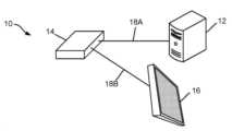
도 1은 종래의 LED 사이니지 디스플레이(10)의 실시예를 도시한다. 도시된 바와 같이, LED 사이니지 디스플레이 시스템(10)은 케이블(18B)를 통해 센더 박스에 전기적으로 연결된 LED 사이니지 디스플레이(16)를 포함한다. 센더 박스(14)는 케이블(18A)을 통해 컴퓨터(12)에 전기적으로 연결된다. 데이터는 먼저 케이블(18A)을 통해 컴퓨터(12)로부터 센더 박스(14)로 전송된다. 이후, 센더 박스(14)는 케이블(18B)을 통해 수신된 데이터를 LED 사이니지 디스플레이(16)의 캐비넷 내에 설치된 LED 수신기(미도시)로 전송한다. LED 수신기에 의해 수신된 데이터는 LED 사이니지 디스플레이(16)의 LED의 조명을 제어(예를 들어, 켜기, 끄기, 조명 강도, 색상 등)하기 위해 중앙 제어기(미도시)에 의해 사용된다.1 shows an embodiment of a conventional
도 2에서 도시된 바와 같이, 종래의 디지털 LED 사이니지 디스플레이(16)는 중앙 제어기(32)와 리본 케이블과 같은 케이블(38)을 통해 중앙 제어기(32)에 연결된 하나 이상의 LED 디스플레이 모듈(34)을 포함한다.As shown in FIG. 2, a conventional digital
각각의 LED 디스플레이 모듈(34)은 복수의 LED(36) 및 하나 이상의 LED 드라이버(미도시)를 포함한다. LED 드라이버는 LED(36)에 전달되는 전력을 조절함으로써, LED의 조명을 제어(예를 들어, 끄기, 켜기, 조명 강도, 색상 등)한다. LED 드라이버의 구동 용량에 따라, 각각의 LED 드라이버는 LED(36)의 서브세트, 예를 들어, 4, 8, 16개의 LED(36)에 전기적으로 연결되고 조절할 수 있다.Each
각각의 LED 디스플레이 모듈(34)에서, 모든 LED 드라이버는 케이블(38)을 통해 중앙 제어기(32)에 배선된다. 따라서, 종래의 디지털 LED 사이니지 디스플레이(16)는, 특히 많은 수의 LED(36)를 갖는 디지털 LED 사이니지 디스플레이(16)(예를 들어, 큰 디스플레이 표면을 구비한 디지털 LED 사이니지)는 일반적으로 많은 숫자의 케이블/와이어를 포함한다. 불행하게도, 이러한 케이블은 종종 종래의 디지털 LED 사이니지 디스플레이(10)의 고장 포인트이다.In each
또한, 종래의 LED 사이니지 디스플레이에서 사용되는 데이터 통신 방법은 많은 단점을 갖는다. 예를 들어, 종래의 LED 사이니지 디스플레이(10)는 일반적으로 LED(36)를 제어하도록 컴퓨팅 장치로부터 LED 사이니지 디스플레이(10)로 데이터를 전송하기 위하여 센더 박스, 수신기 카드, 중앙 제어기, LED 드라이버 등과 같은 복수의 데이터 통신 컴포넌트를 포함하여, 이에 의해 LED 사이니지 디스플레이의 비용이 증가된다.In addition, the data communication method used in the conventional LED signage display has many disadvantages. For example, a conventional
복수의 데이터 통신 컴포넌트가 요구됨에 따라, 종래 LED 사이니지 디스플레이(10)에서의 통신 시스템은 개별적인 데이터 통신 컴포넌트 각각의 고장 위험 증가로 인해 신뢰성이 떨어질 수도 있다. 또한, 각각의 LED 드라이버는 중앙 제어기에 유선 연결됨에 따라, 다수의 LED를 갖는 디지털 LED 사이니지 디스플레이(10)는 일반적으로 LED(36)를 제어하기 위해 다수의 와이어를 포함하여, 디지털 LED 사이니지 디스플레이(10)의 비용을 증가시키고, 리본 케이블의 와이어가, 특허 실외 용도로 사용시, 시간에 지남에 따라 분리 및/또는 손상될 위험이 높기 때문에 신뢰성을 감소시킨다.As a plurality of data communication components are required, the communication system in the conventional
여기에서, 발광 다이오드(LED) 장치의 실시 양태들이 개시된다. 본 발명의 일 실시 양태에 따르면, LED 장치는: (i) 하나 이상의 LED 디스플레이 모듈로서, 각각의 LED 디스플레이 모듈은 적어도 하나의 무선 통신 유닛을 포함하고 LED 디스플레이 모듈 안에 통합된, LED 디스플레이 모듈; (ii) 복수의 LED 디스플레이 서브모듈로써, 복수의 LED 디스플레이 서브모듈 각각은 하나 이상의 LED를 갖는, LED 디스플레이 서브모듈; 및 (iii) 복수의 LED의 조명을 조절하기 위하여 LED 디스플레이 서브모듈에 지시하기 위해 하나 이상의 무선 통신 유닛과 무선 통신하기 위한 게이트웨이;를 포함한다.Here, embodiments of a light emitting diode (LED) device are disclosed. According to one embodiment of the present invention, an LED device includes: (i) one or more LED display modules, each LED display module comprising at least one wireless communication unit and integrated into the LED display module; (ii) a plurality of LED display submodules, each of the plurality of LED display submodules having one or more LEDs; and (iii) a gateway for wireless communication with one or more wireless communication units to instruct the LED display submodule to adjust the illumination of the plurality of LEDs.
본 발명의 일 실시 양태에 따르면, LED 장치가 제공된다. LED 장치는: 적어도 하나의 LED 디스플레이 모듈, 복수의 LED 및 적어도 하나의 통신 유닛을 포함하는 적어도 하나의 LED 디스플레이 모듈; 및 적어도 하나의 통신 유닛에 기능적으로 커플링된 게이트웨이로써, 게이트웨이는 LED 장치를 제어하기 위해 하나 이상의 명령을 무선으로 수신하고, 수신된 하나 이상의 명령에 응답으로, 복수의 LED의 조명을 조절하기 위해 무선으로 또는 직류(DC) 전력선을 통해 하나 이상의 무선 통신 유닛으로 하나 이상의 지시(instruction)를 전송하도록 구성된, 게이트웨이;를 포함한다.According to one embodiment of the present invention, an LED device is provided. The LED device includes: at least one LED display module including at least one LED display module, a plurality of LEDs, and at least one communication unit; and a gateway operatively coupled to the at least one communication unit, wherein the gateway is configured to wirelessly receive one or more commands to control the LED device and, in response to the received one or more commands, to adjust illumination of the plurality of LEDs. and a gateway, configured to transmit one or more instructions to one or more wireless communication units wirelessly or over a direct current (DC) power line.
일부 실시 양태에서, 각각의 LED 디스플레이 모듈은, 복수의 LED 디스플레이 서브모듈로서, 각각의 LED 디스플레이 서브모듈은 복수의 LED 서브세트를 포함하는, LED 디스플레이 서브모듈;을 더 포함한다.In some embodiments, each LED display module further includes a plurality of LED display submodules, each LED display submodule comprising a plurality of LED subsets.
일부 실시 양태에서, 각각의 LED 디스플레이 모듈은 복수의 통신 유닛을 포함하고, 복수의 LED 디스플레이 서브모듈 각각은 복수의 통신 유닛 중 하나를 포함한다.In some embodiments, each LED display module includes a plurality of communication units, and each of the plurality of LED display submodules includes one of the plurality of communication units.
일부 실시 양태에서, 각각의 LED 디스플레이 모듈은 단지 하나의 통신 유닛을 포함한다.In some embodiments, each LED display module includes only one communication unit.
일부 실시 양태에서, 각각의 LED 서브모듈은 적어도 하나의 통신 유닛과 신호 통신하는 제어 유닛을 더 포함하고, LED 서브모듈에서 복수의 LED의 조명을 조절하도록 구성된다.In some embodiments, each LED sub-module further includes a control unit in signal communication with the at least one communication unit and is configured to regulate illumination of the plurality of LEDs in the LED sub-module.
일부 실시 양태에서, 적어도 하나의 LED 디스플레이 모듈은 비평면 디스플레이 표면으로 구성될 수 있는 가요성 디스플레이 표면을 포함한다.In some embodiments, the at least one LED display module includes a flexible display surface that can be configured as a non-planar display surface.
일부 실시 양태에서, 전력선은 약 48V의 전압을 갖는다.In some embodiments, the power line has a voltage of about 48V.
일부 실시 양태에서, 게이트웨이는 DC 전력선을 통해 적어도 하나의 통신 유닛과 통신하도록 구성되고; 적어도 하나의 통신 유닛은, 간섭 및/또는 노이즈를 줄이기 위해 DC 전력선의 전기적인 전류를 필터링하는 저역 통과 필터(LPF)를 포함한다.In some embodiments, the gateway is configured to communicate with the at least one communication unit via a DC power line; At least one communication unit includes a low pass filter (LPF) that filters the electrical current of the DC power line to reduce interference and/or noise.
일부 실시 양태에서, 적어도 하나의 통신 유닛은 LED의 데이터를 수집하고 LED의 조명을 조절하기 위해 데이터 획득 컴포넌트를 더 포함한다.In some embodiments, the at least one communication unit further includes a data acquisition component to collect data of the LEDs and adjust illumination of the LEDs.
일부 실시 양태에서, 적어도 하나의 통신 유닛은, 데이터 획득 컴포넌트로 및 데이터 획득 컴포넌트로부터 데이터를 전송하기 위해 데이터 획득 컴포넌트에 기능적으로 커플링된 통신 컴포넌트를 더 포함한다.In some embodiments, the at least one communication unit further includes a communication component functionally coupled to the data acquisition component for transferring data to and from the data acquisition component.
본 발명의 일 실시 양태에 따르면, LED 디스플레이 모듈이 제공된다. LED 디스플레이 모듈은: 복수의 LED 디스플레이 서브모듈로서, 각각의 LED 디스플레이 서브모듈은 하나 이상의 LED를 포함하는, LED 디스플레이 서브모듈; 하나 이상의 LED의 조명을 조절하기 위해 복수의 LED 디스플레이 서브모듈과 통신하도록 구성된 통신 허브; 및 무선 통신 허브와 통신하고 하나 이상의 컴퓨터 장치와 무선 통신하도록 구성된 게이트웨이;를 포함한다.According to one embodiment of the present invention, an LED display module is provided. The LED display module includes: a plurality of LED display submodules, each LED display submodule including one or more LEDs; a communications hub configured to communicate with a plurality of LED display submodules to adjust illumination of one or more LEDs; and a gateway configured to communicate with the wireless communication hub and wirelessly communicate with one or more computer devices.
일부 실시 양태에서, LED 디스플레이 모듈은 복수의 LED 디스플레이 서브모듈을 수용하기 위한 복수의 포켓 및 통신 허브를 수용하기 위한 중앙 포켓을 포함하는 가요성 하우징 구조를 더 포함한다.In some embodiments, the LED display module further includes a flexible housing structure that includes a plurality of pockets for accommodating the plurality of LED display submodules and a central pocket for accommodating the communication hub.
일부 실시 양태에서, 통신 허브는 게이트웨이와 무선 통신을 위한 무선 통신 허브이다.In some embodiments, the communication hub is a wireless communication hub for wireless communication with a gateway.
일부 실시 양태에서, 통신 허브는 DC 전력선을 통해 게이트웨이와 통신하기 위한 유선 통신 허브이다.In some embodiments, the communications hub is a wired communications hub for communicating with a gateway over a DC power line.
일부 실시 양태에서, DC 전력선은 약 48V의 전압을 갖는다.In some embodiments, the DC power line has a voltage of about 48V.
일부 실시 양태에서, 통신 허브는 간섭 및/또는 노이즈를 줄이기 위하여 DC 전력선의 전기적 전류를 필터링하기 위해 저역 통과 필터(LPF)를 포함한다.In some embodiments, the communication hub includes a low pass filter (LPF) to filter the electrical current of the DC power line to reduce interference and/or noise.
일부 실시 양태에서, 통신 허브는 LED의 데이터를 수집하고 LED의 조명을 조절하기 위하여 데이터 획득 컴포넌트를 더 포함한다.In some embodiments, the communication hub further includes a data acquisition component to collect data of the LEDs and adjust the lighting of the LEDs.
일부 실시 양태에서, 통신 허브는 데이터 획득 컴포넌트로 및 데이터 획득 컴포넌트로부터 데이터를 전송하기 위해 데이터 획득 컴포넌트에 기능적으로 커플링된 통신 컴포넌트를 더 포함한다.In some embodiments, the communication hub further includes a communication component functionally coupled to the data acquisition component for transferring data to and from the data acquisition component.
본 발명의 실시 양태는, 다른 도면에서 동일한 참조 번호는 동일한 구성 요소는 나타내는 다음 도면들을 참조하여 설명될 것이다:
도 1은 데이터가 컴퓨터로부터 LED 사이니지 디스플레이로 전송되는 방법을 나타내는 종래의 LED 사이니지의 개략도이다;
도 2는 도 1에 도시된 종래의 디지털 LED 사이니지 디스플레이의 중앙 제어기의 블록 다이어그램이다;
도 3A 및 3B는 본 발명의 일부 실시 양태에 따른 LED 사이니지 디스플레이를 갖는 LED 디스플레이 시스템의 간략화된 개략적인 블록 다이어그램이다;
도 4A는 도 3A에 도시된 LED 디스플레이 시스템의 LED 사이니지 디스플레이의 가요성 LED 디스플레이 모듈의 개략적인 사시도로서, 복수의 LED 디스플레이 서브모듈은 가요성 LED 모듈을 갖는다;
도 4B는 곡면 디스플레이 표면으로 구성된, 도 4A에 도시된 가요성 LED 디스플레이 모듈의 개략적인 사시도이다;
도 5A는 도 4A에 도시된 LED 디스플레이 모듈의 각각의 LED 디스플레이 서브모듈 내에서 LED 전력 통합 회로(IC) 칩의 개락적인 사시도로서, LED 전력 IC 칩은 칩상에 통합된 무선 통신 유닛을 갖는다;
도 5B는 도 4A에 도시된 LED 디스플레이 모듈의 LED 서브모듈의 간락화된 블록 다이어그램이다;
도 6은 도 3A에 도시된 LED 디스플레이 시스템의 소프트웨어 구조를 도시하는 블록 다이어그램이다;
도 7은 본 발명의 일부 실시 양태에 따른 도 3A에 도시된 LED 디스플레이 시스템의 소프트웨어 구조를 도시하는 블록 다이어그램이다;
도 8A는 본 발명의 일부 대안적인 실시 양태에 따른 LED 사이니지 디스플레이를 갖는 LED 디스플레이 시스템의 개략도이다;
도 8B는 도 8A에 도시된 LED 디스플레이 시스템의 LED 모듈의 개략적인 사시도로서, LED 모듈은 가요성 하우징 구조를 포함한다;
도 9는 도 8A에 도시된 LED 디스플레이 시스템의 소프트웨어 구조를 도시한 블록 다이어그램이다;
도 10은 본 발명의 일부 대안적인 실시 양태에 따른 LED 사이니지 디스플레이를 갖는 LED 디스플레이 시스템의 개략도이다;
도 11은 도 10에 도시된 LED 디스플레이 시스템의 각각의 LED 디스플레이 모듈 내에 통합된 통신 서브-허브의 개략적인 사시도이고;
도 12는 도 11에 도시된 통신 서브-허브의 PLC 유닛의 간략화된 회로도이다;Embodiments of the present invention will be described with reference to the following drawings in which like reference numbers indicate like elements in different drawings:
1 is a schematic diagram of a conventional LED signage showing how data is transmitted from a computer to an LED signage display;
Fig. 2 is a block diagram of a central controller of the conventional digital LED signage display shown in Fig. 1;
3A and 3B are simplified schematic block diagrams of LED display systems having LED signage displays in accordance with some embodiments of the invention;
Fig. 4A is a schematic perspective view of a flexible LED display module of the LED signage display of the LED display system shown in Fig. 3A, wherein a plurality of LED display submodules have flexible LED modules;
Fig. 4B is a schematic perspective view of the flexible LED display module shown in Fig. 4A, constructed with a curved display surface;
Fig. 5A is a schematic perspective view of a LED power integrated circuit (IC) chip within each LED display sub-module of the LED display module shown in Fig. 4A, the LED power IC chip having an integrated wireless communication unit on the chip;
Fig. 5B is a simplified block diagram of the LED sub-module of the LED display module shown in Fig. 4A;
Fig. 6 is a block diagram showing the software structure of the LED display system shown in Fig. 3A;
7 is a block diagram illustrating the software structure of the LED display system shown in FIG. 3A in accordance with some embodiments of the present invention;
8A is a schematic diagram of a LED display system having an LED signage display according to some alternative embodiments of the present invention;
Fig. 8B is a schematic perspective view of an LED module of the LED display system shown in Fig. 8A, wherein the LED module includes a flexible housing structure;
Fig. 9 is a block diagram showing the software structure of the LED display system shown in Fig. 8A;
10 is a schematic diagram of a LED display system having an LED signage display according to some alternative embodiments of the present invention;
Fig. 11 is a schematic perspective view of a communication sub-hub incorporated in each LED display module of the LED display system shown in Fig. 10;
Fig. 12 is a simplified circuit diagram of a PLC unit of the communication sub-hub shown in Fig. 11;
여기에서, LED 디스플레이의 실시 양태가 개시된다. 일부 실시 양태에서, LED 장치는 LED 사이니지 디스플레이일 수 있다. 일부 실시 양태에서, LED 장치는, 구부릴 수 있고 비평면 디스플레이 표면을 형성할 수 있는 하나 이상의 가요성 LED 모듈을 갖는 LED 사이니지 디스플레이일 수 있다.Here, an embodiment of an LED display is disclosed. In some embodiments, the LED device may be an LED signage display. In some embodiments, the LED device may be an LED signage display having one or more flexible LED modules that can be bent and form a non-planar display surface.
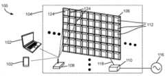
도 3A 및 3B를 참조하면, LED 디스플레이 시스템이 도시되고 일반적으로 참조 번호 100을 사용하여 표시된다. 이러한 실시 양태에서 LED 디스플레이 시스템(100)은 WI-FI®(WI-FI는 미국 조지아주 애틀랜타 DBA Hartsfield-Jackson Atlanta International Airport Municipal Corp.의 등록 상표이다), 블루투스®(BLUETOOTH, BLUETOOTH는 미국 워싱턴주 커클랜드 Bluetooth Sig Inc.의 등록 상표이다), 직비®(ZIGBEE, ZIGBEE는 미국 캘리포니아 샌 라몬 ZigBee Alliance Corp.의 등록 상표이다), (GSM, CDMA, LET 등과 같은) 무선 이동 통신 기술 등과 같은 임의의 적합한 무선 통신 기술과 같은 적합한 무선 통신 기술을 이용하여 하나 이상의 데스크톱 컴퓨터, 랩톱 컴퓨터, 스마트폰, 태블릿 등과 같은 하나 이상의 컴퓨팅 장치(102)와 무선 통신하는 LED 사이니지 디스플레이(104)를 포함한다.Referring to FIGS. 3A and 3B , an LED display system is shown and generally designated using the
LED 사이니지 디스플레이(104)는 하나 이상의 LED 디스플레이 모듈(106)(도 3A는 LED 디스플레이 모듈의 후면을 나타내고, 도 3B는 LED 디스플레이 모듈의 전면을 나타냄), 게이트웨이(108) 및 교류(AC) 대 직류(DC) 전원 공급기(AC/DC 전원 공급기로 표시됨)를 포함한다. AC/DC 전원 공급기(110)는 외부 전원(116)으로부터의 전력을 DC 전력으로 변환하고, 케이블(118)을 통해 DC 전력을 LED 디스플레이 모듈(106)로 출력한다.The
이러한 실시 양태에서, 하나 이상의 LED 디스플레이 모듈(106)은 게이트웨이(108)와 무선 통신한다. 또한, 게이트웨이(108)는 컴퓨터 장치(102)와 LED 디스플레이 모듈(106) 사이에서 데이터를 전송하기 위해 하나 이상의 컴퓨팅 장치(102)와 무선 통신한다.In this embodiment, one or more
또한, (LED 디스플레이 모듈(106)의 후면을 도시한) 도 4A를 참조하면, 이러한 실시 양태에서, 각각의 LED 디스플레이 모듈(106)은 가요성 LED 디스플레이 모듈이고, 상기 각각의 LED 디스플레이 모듈(106)은 가요성 방식으로 서로 커플링되는 복수의 LED 디스플레이 서브모듈(112)을 포함한다. 각각의 LED 디스플레이 서브모듈(112)는 하나 이상의 LED(114)를 포함한다. 따라서, 일반적으로 평면 디스플레이 표면을 갖는 종래의 LED 사이니지 디스플레이와 달리, 가요성 LED 디스플레이 모듈(106)은 예를 들어, 도 4B에 도시된 곡면 디스플레이 표면의 비평면 디스플레이 표면을 형성하도록 구성될 수 있다. 다른 실시 양태에서, 적어도 하나의 LED 디스플레이 모듈(106)은 종래의 비-가요성 LED 디스플레이 모듈일 수 있다.4A (which shows the rear side of the LED display module 106), in this embodiment, each
이러한 실시 양태에서, 각각의 LED 디스플레이 서브모듈(112)은 서브모듈 내에 통합된 무선 통신 유닛을 포함한다. 도 5A는, 게이트웨이(108)와 무선 통신하기 위한 무선 통신 유닛(124)을 포함하는 LED 전력 통합 회로(IC) 칩(122)의 개략적인 사시도이다In this embodiment, each
도 5B는 LED 서브모듈(112)의 간략화된 블록 다이어그램이다. 도시된 바와 같이, LED 서브모듈(112)은, 서브모듈 내에 하나 이상의 LED(114)와 LED 서브모듈(112)의 LED(114)에 개별적으로 전력을 공급하고 그 LED(114)를 제어하기 위한 다기능, 통합 솔루션을 제공하는 LED 전력 통합 회로(IC) 칩(122)을 포함하고 통합한다. LED 전력 IC(122)는 무선 주파수(RF) 송수신기와 같은 무선 통신 유닛(124), 디지털 제어 유닛(126), 또는 다중-출력 DC/DC 변환기(128)를 포함한다.5B is a simplified block diagram of
무선 통신 유닛(124)은, 디지털 사이니지(100)의 게이트웨이(108)(또는 중앙 제어기)로부터 색상, 조명 강도 등과 같은 제어 정보를 수신한다. 이러한 실시 양태에서, 게이트웨이(108)는, 향상된 LED 디스플레이 모듈(106)으로부터 물리적으로 분리되어 있고, 하나 이상의 컴퓨팅 장치(102)로부터 수신된 지시에 응답하여, 각각의 LED 서브모듈(112) 내의 대응하는 LED(114)를 제어하기 위해, 무선 통신 연결부(109)를 통해 각각의 LED 서브모듈(112)의 LED 전력 IC(122)의 무선 통신 유닛(124)과 통신한다. 또한, 무선 통신 유닛(124)은 진단 및 문제 해결 목적으로 LED 서버모듈(112)의 각각의 LED의 상태를 컴퓨팅 장치(102)에 보고한다. 따라서, 무선 통신 유닛(124)은 종래의 설계에서 요구되는 제어 와이어의 필요성을 제거한다.The
디지털 제어 유닛(126)은 다중-출력 DC/DC 변환기(128)를 위해 제어 신호를 제공한다. 또한, 무선 통신 유닛(124)으로부터 높은-레벨 신호를 수신한 이후에, 신호에서 정보를 디코딩하고, 다중-출력 DC/DC 변환기(128)의 금속 산화막 반도체 전계효과 트랜지스터(MOSFET) 스위치와 같은 디지털 스위치를 위한 적합한 게이트웨이 신호를 생성한다. 각각의 디지털 제어 유닛(126)은 최적화된 방법으로 각각의 LED 서브모듈(112)의 LED(114)를 제어하기 위한 실질적인 유연성을 제공하고, 무선 통신 유닛(124)을 통해 필요한 정보를 업데이트하고, 시스템 엡데이트를 수신한다.
도 3A 및 3B에 도시된 실시 양태를 참조하면, 컴퓨팅 장치(102)는, 하나 이상의 LED 디스플레이 서브모듈(106)에 걸친 LED 사이니지 디스플레이 표면(120)에 영상을 디스플레이 하기 위해 무선 통신 유닛(124)을 통해 LED 디스플레이 서브모듈(112)과 무선으로 통신할 수 있다. 또한, 일부 실시 양태에서, 각각의 LED 디스플레이 서브모듈(112)은 서브모듈의 상태, 진단 등을 레포팅하기 위해 컴퓨팅 장치(102)에 데이터를 전송할 수 있다.Referring to the embodiment shown in FIGS. 3A and 3B , a
따라서, 이러한 설계로, LED 디스플레이 시스템(100)은 컴퓨팅 장치(102)와 LED 디스플레이 모듈(106) 사이의 데이터 통신을 위한 데이터 케이블 및 센더 박스의 필요성을 제거한다.Thus, with this design, the
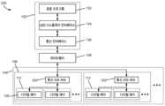
도 6은 LED 디스플레이 시스템(100)의 소프트웨어 구조(130)를 도시한 블록 다이어그램이다. 도시된 바와 같이, 컴퓨팅 장치(102)는 응용 프로그램(132), LED 디스플레이 소프트웨어 드라이버와 같은 LED 디스플레이 인터페이스(134), 및 무선 통신 인터페이스(136)를 포함하고 실행한다. 응용 프로그램(132)은, 이미지를 디스플레이하기 위해 LED 사이니지 디스플레이(104)에 지시 및/또는 그 상태를 레포팅하기 위해 LED 사이니지 디스플레이(104)에 지시하는 등과 같은 응용-레벨 동작을 수행하도록 LED 디스플레이 인터페이스(134)와 통신한다.6 is a block diagram illustrating the
LED 디스플레이 인터페이스(134)는, 응용 프로그램(132)로부터 응용-레벨 응용-레벨 명령을 수신하고, 응용-레벨 지시를 LED 사이니지 디스플레이(104)에 의해 수행될 수 있는 머신-레벨 지시로 변환하고, 머신-레벨 지시를 컴퓨팅 장치(102)의 통신 인터페이스(136)를 통해 게이트웨이(108)로 전송한다.The
예를 들어, LED 사이니지 디스플레이(104)는 복수의 LED 디스플레이 모듈(106)을 포함할 수 있다. 응용 프로그램(132)이 하나 이상의 LED 디스플레이 모듈(106)에 걸친 LED 사이니지 디스플레이(104)상에 이미지를 디스플레이할 때, 상기 응용 프로그램(132)은 디스플레이될 이미지를 응용-레벨 이미지-디스플레이 지시와 함께 LED 디스플레이 인터페이스(134)에 전송한다.For example, the
LED 디스플레이 인터페이스(134)는 이미지-디스플레이 지시를 하나 이상의 머신-레벨 이미지-디스플레이 지시로 변환하고, 각각의 LED 디스플레이 모듈(106)의 각각의 LED 디스플레이 서브모듈(112)에 디스플레이될 때 필요한 이미지 부분을 결정하여 표시하고, 통신 인터페이스(136)를 통해 표시된 이미지 및 머신-레벨 이미지-디스플레이 지시 세트를 게이트웨이(108)로 무선으로 전송한다.The
게이트웨이(108)는 표시된 이미지 및 머신-레벨 이미지-디스플레이 지시 세트를 LED 디스플레이 인터페이스(134)로부터 수신하고, 각각의 LED 디스플레이 서브모듈(112)로 전송될 데이터(지시 및 이미지 데이터를 포함하는)를 식별하고, 식별된 데이터를 각각의 LED 디스플레이 서브모듈(112)로 무선으로 전송한다.
각각의 디스플레이 서브모듈(112)의 RF 송수신기(124)는 데이터를 수신하고, 서브모듈의 각각의 LED의 조명(예를 들어, 켜기, 끄기, 조명 강도, 색상 등)을 조절하기 위해 LED 디스플레이 서브모듈의 디지털 제어 유닛(126)에 지시한다. 결과적으로, 이미지는 LED 사이니지 디스플레이(104)의 하나 이상의 LED 디스플레이 모듈(106)에 걸쳐 디스플레이된다.The
도 7은, 일부 대안적인 실시 양태에 따른, LED 디스플레이 시스템(100)의 소프트웨어 구조(150)를 도시한 블록 다이어그램이다. 소프트웨어 구조(150)는, 이러한 실시 양태에서, 컴퓨팅 장치(102)가 어떠한 LED 디스플레이 인터페이스를 포함하지 않는 것을 제외하고, 도 6에 도시된 소프트웨어 구조(130)와 유사하다. 대신에, 게이트웨이(108)는, 예를 들어, 펌웨어 프로그램 형태인 LED 디스플레이 인터페이스(154)를 포함한다.7 is a block diagram illustrating the
이미지가 디스플레이될 때, 컴퓨팅 장치(102)에서 구동되는 응용 프로그램(132)은 이미지-디스플레이 지시 및 디스플레이될 이미지를 무선 통신 인터페이스(136)를 통해 게이트웨에(108)로 무선으로 전송한다. 게이트웨이(108)는 이미지-디스플레이 지시 및 이미지를 게이트웨이의 무선 통신 인터페이스(152)를 통해 무선으로 수신하고, 이미지-디스플레이 지시를 하나 이상의 머신-레벨 이미지-디스플레이 지시로 변환하기 위해 LED 디스플레이 인터페이스(154)를 이용하고, 각각의 LED 디스플레이 서브모듈(112)에 전송될 데이터(지시 및 이미지 데이터를 포함하는)를 식별하고, 무선 통신 인터페이스(152)를 통해 각각의 LED 디스플레이 서브모듈(112)로 식별된 데이터를 무선으로 전송한다.When an image is displayed, the
각각의 LED 디스플레이 서브모듈(112)의 RF 송수신기(124)는, 상기 데이터를 수신하고, 서브모듈의 각각의 LED의 조명(예를 들어, 끄기, 켜기, 조명 강도, 색상 등)을 조절하기 위해 LED 디스플레이 서브모듈(112)의 디지털 제어 유닛(126)에 지시한다. 결과적으로, 이미지는 LED 사이니지 디스플레이(104)의 하나 이상의 LED 디스플레이 모듈(106)에 걸쳐 디스플레이된다.The
도 8A는 일부 대안적인 실시 양태에 따른 LED 디스플레이 시스템(200)을 도시한다. 도 3에 도시된 LED 디스플레이 시스템(100)과 유사하게, 이러한 실시 양태에서 LED 디스플레이 시스템(200)은 적합한 무선 통신 기술을 사용하여 LED 사이니지 디스플레이(104)와 무선 통신하는 하나 이상의 컴퓨팅 장치(102)를 포함한다. 이러한 실시 양태에서 LED 사이니지 디스플레이(104)는 게이트웨이(108)와 무선 통신하는 하나 이상의 LED 디스플레이 모듈(106)을 포함한다. 또한, 게이트웨이(108)는 컴퓨팅 장치(102) 및 LED 디스플레이 모듈(106) 사이에서 데이터를 전송하기 위해 하나 이상의 컴퓨팅 장치(102)와 무선 통신한다.8A shows an
각각의 LED 디스플레이 모듈(106)은 가요성 LED 디스플레이 모듈일 수 있고, 유연한 방법으로 서로 커플링되는 복수의 LED 디스플레이 서브모듈(112)을 포함할 수 있다. 따라서, 가요성 LED 디스플레이 모듈(106)은 비평면 디스플레이 표면을 형성하도록 구성될 수 있다. 다른 실시 양태에서, 적어도 하나의 LED 디스플레이 모듈(106)은 종래의 비-가요성 LED 디스플레이 모듈일 수 있다.Each
도 3에 도시된 LED 디스플레이 시스템(100)과 다르게, LED 디스플레이 모듈(106)의 서브모듈(112)은 임의의 무선 통신 유닛을 포함하지 않는다. 대신에, 각각의 LED 디스플레이 모듈(106)은 적합한 회로(미도시)를 통해 디스플레이 모듈의 서브모듈(112)에 연결된 무선 통신 서브-허브(202)를 디스플레이 모듈 내에 더 포함하고 통합한다.Unlike the
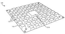
또한, 도 8B에 도시된 바와 같이, 이러한 실시 양태에서 LED 디스플레이 모듈(106)은 가요성 고무와 같은 적합한 가요성 재료로 만들어진 가요성 하우징 구조(119)를 포함한다. 가요성 하우징 구조(119)는 복수의 LED 디스플레이 서브모듈(112)(도 8B에 미도시)을 수용하기 위한 복수의 셀 또는 포켓(121)과, 무선 통신 서브-허브(도 8B에 미도시)를 수용하기 위한 중앙 포켓(121A)을 포함한다. 또한, 가요성 하우징 구조(119)는, 포켓(121, 121A)에 수용되는 LED 디스플레이 서브모듈(112) 및 무선 통신 서브-허브(202)를 상호 연결하기 위해 그 하우징 구조 내에 내장된 복수의 전기 도전체 또는 와이어를 포함한다.8B, the
도 9는 LED 디스플레이 시스템(100)의 소프트웨어 구조(230)를 도시한 블록 다이어그램이다. 도시된 바와 같이, 컴퓨팅 장치(102)는 응용 프로그램(132), LED 디스플레이 인터페이스(134), 및 무선 통신 인터페이스(136)를 포함하고 실행한다. 응용 프로그램(132)은, 이미지를 디스플레하도록 LED 사이니지 디스플레이(104)에 지시하거나, LED 사이니지 디스플레이의 상태를 레포팅하도록 LED 사이니지 디스플레이(104)에 지시하는 것과 같은 응용-레벨 동작을 수행하기 위해 LED 디스플레이 인터페이스(134)와 통신한다.9 is a block diagram illustrating the
LED 디스플레이 인터페이스(134)는 응용 프로그램(132)로부터 응용-레벨 지시를 수신하고, 응용-레벨 지시를 LED 사이니지 디스플레이(104)에 의해 실행될 수 있는 머신-레벨 지시로 변환하고, 컴퓨팅 장치(102)의 통신 인터페이스(136)를 통해 게이트웨이(108)로 머신-레벨 지시를 전송한다.The
예를 들어, LED 사이니지 디스플레이(104)는 복수의 LED 디스플레이 모듈(106)을 포함할 수 있다. 응용 프로그램(132)이 복수의 LED 디스플레이 모듈(106)에 걸쳐 LED 사이니지 디스플레이(104)상에 이미지를 디스플레이할 때, 용용 프로그램(132)은, LED 디스플레이 인터페이스(134)에 응용-레벨 이미지 디스플레이 지시와 함께 디스플레이될 이미지를 전송한다.For example, the
LED 디스플레이 인터페이스(134)는 이미지-디스플레이 지시를 하나 이상의 머신-레벨 이미지-디스플레이 지시로 변환하고, 각각의 LED 디스플레이 모듈(106)의 각각의 LED 디스플레이 서브모듈(112) 상에 디스플레이되는데 필요한 이미지 부분을 결정하여 표시하고, 통신 인터페이스(136)를 통해 게이트웨이(108)로 상기 표시된 이미지 및 머신-레벨 이미지-디스플레이 지시 세트를 무선으로 전송한다.The
게이트웨이(108)는 LED 디스플레이 드라이버(134)로부터 표시된 이미지 및 머신-레벨 이미지-디스플레이 지시 세트를 수신하고, 각각의 LED 디스플레이 모듈(106)에 전송될 데이터(지시 및 이미지 데이터를 포함하는)를 식별하고, 각각의 LED 디스플레이 모듈(106)의 통신 서브-허브(202)에 식별된 데이터를 무선으로 전송한다.
각각의 LED 디스플레이 모듈(106)에서, LED 디스플레이 모듈의 통신 서브-허브(202)는 게이트웨이(108)로부터 상기 데이터를 수신하고, 각각의 LED 디스플레이 서브모듈(112)에 전송될 데이터(지시 및 이미지 데이터를 포함하는)를 식별하고, 각각의 LED 디스플레이 서브모듈(112)의 디지털 제어 유닛(126)에 식별된 데이터를 전송한다. 이에 응답으로, LED 디스플레이 서브모듈(112)의 각각의 디지털 제어 유닛(126)은 LED 디스플레이 서브모듈의 각각의 LED의 조명을 조절(예를 들어, 끄기, 켜기, 조명 강도, 색상 등)한다. 결과적으로, 상기 이미지는 LED 사이니지 디스플레이(104)의 복수의 LED 디스플레이 모듈(106)에 걸쳐 디스플레이된다.In each
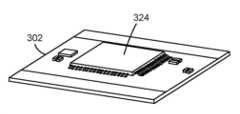
도 10은 대안적인 실시 양태에 따른 LED 디스플레이 시스템(300)을 도시한다. 이러한 실시 양태에서, 각각의 LED 디스플레이 모듈(106)이 전력선(118)을 통해 게이트웨이(108)와 통신하는 유선 통신 서브-허브(302)를 포함하는 것을 제외하고, LED 디스플레이 시스템(300)은 도 8A에 도시된 LED 디스플레이 시스템(200)과 유사하다. 도 10에서, 참조 번호(118)로 표시된 굵은 선은 LED 디스플레이 모듈(106)에 전력을 공급하기 위한 전력선(118)을 나타내고, 참조 번호(118)로 표시된 얇은 링크는 데이터 통신을 위한 같은 전력선을 나타낸다.10 shows an
이러한 실시 양태의 장점은 게이트웨이(108)와 마찬가지로 상기 LED 디스플레이 모듈(106)이 데이터 통신 케이블로서 전력 코드를 사용할 수 있고, 따라서, 별도의 데이터 통신 케이블 또는 무선 통신 유닛의 필요성이 없다는 것이다.An advantage of this embodiment is that, like the
도 11은 유선 통신 서브-허브(302)의 개략적인 사시도를 도시한다. 이러한 실시 양태에서, 유선 통신 서브-허브(302)는 게이트웨이(108)와 통신하기 위해 전력선 통신(Power Line Communication, PLC) 유닛(324)을 포함한다.11 shows a schematic perspective view of a
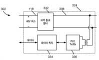
도 12는 통신 서브-허브(302)의 PLC 유닛(324)의 간략화된 회도로이다. 도시된 바와 같이, PLC 유닛(324)은 저역-통과 필터(LPF) 블록(332), 데이터 취득 블록(334), 및 PLC 통신 블록(336)을 포함한다. 통신 서브-허브가 전력선을 통해 게이트웨이(108)와 통신하는 것을 제외하고, LED 디스플레이 시스템(300)의 소프트웨어 구조는 도 9에 도시된 소프트웨어 구조와 유사하다.12 is a simplified circuit diagram of the
도 12에 도시된 바와 같이, LPF 블록(332)은 DC 전력선(118)에 전기적으로 연결된다. 전술한 바와 같이, DC 전력선(118)은 AC/DC 변환기(110)를 통해 AC 전원(116)에 전기적으로 연결되고(도 3 및 도 10 참조), 일부 실시 양태에서 약 48V의 DC 전압을 가질 수 있다.As shown in FIG. 12 , LPF block 332 is electrically connected to
LPF 블록(332)은 간섭 및/또는 노이즈를 줄이기 위해 전류를 필터링한다. 데이터 취득 블록(334)은 디지털 제어 유닛(126)으로부터 데이터를 취득하거나/취득하고, LED의 조명을 조정하기 위해 디지털 제어 유닛(126)을 이용한다. 데이터 송수신기인 PLC 통신 블록(336)은 데이터 취득 블록(334)으로부터 데이터를 수신하고, 전력선(338)을 통해 수신된 데이터를 전송하는데 사용된다. 또한, PLC 통신 블록(336)은 전력선(338)으로부터 데이터를 수신하고, 데이터 취득 블록(334)으로 수신된 데이터를 전송할 수 있다.The
도 10에 도시된 실시 양태에서, 데이터 와이어는, 각각의 LED 디스플레이 서브모듈(112)과 통신 서브-허브(302) 사이의 데이터 통신을 형성하기 위해 요구된다. 도 10에 도시된 LED 디스플레이 시스템(300)과 유사한 일부 대안적인 실시 양태에서, LED 디스플레이 서브모듈(112) 및 통신 서브-허브(302)는 전절한 전력 와이어를 통해, 약 48V(DC 전원)와 같은 일반적인 고전압에 의해 전력을 공급 받는다. 또한, 이러한 실시 양태에서, 각각의 LED 디스플레이 서브모듈(112)은, 48V DC 전력 와이어를 통해 통신 서브-허브(302)와 통신하기 위한 PLC 유닛(324)을 포함한다.In the embodiment shown in FIG. 10 , data wires are required to establish data communication between each
도 3에 도시된 LED 디스플레이 시스템(100)과 유사한 일부 대안적인 실시 양태에서, 각각의 LED 디스플레이 서브모듈(112)은 전력선(304)을 통해 게이트웨이(108)와 직접 통신하기 위해 PLC 유닛(324)을 갖는 유선 통신 서브-허브(302)를 포함한다.In some alternative embodiments similar to
일부 대안적인 실시 양태에서, LED 사이니지 디스플레이는 조명의 목적으로 사용될 수 있는 LED 조명 장치일 수 있다. 이에 따라, 이러한 실시 양태에서 LED 시스템은 LED 조명 시스템으로 지칭된다.In some alternative embodiments, the LED signage display may be an LED lighting device that may be used for lighting purposes. Accordingly, the LED system in this embodiment is referred to as an LED lighting system.
실시 양태가 첨부된 도면을 참조하여 전술되었지만, 통상의 기술자는 첨부된 청구 범위에 의해 정의된 바와 같이 실시 양태의 범위를 벗어나지 않고 변경 및 수정이 이루어질 수 있음을 이해할 것이다.Although the embodiments have been described above with reference to the accompanying drawings, those skilled in the art will appreciate that changes and modifications may be made without departing from the scope of the embodiments as defined by the appended claims.
Claims (19)
Translated fromKorean상기 적어도 하나의 통신 유닛과 기능적으로 커플링된 게이트웨이;
상기 적어도 하나의 통신 유닛에 커플링된 적어도 하나의 제어 유닛; 및
상기 적어도 하나의 제어 유닛 및 상기 복수의 발광 구성 요소에 커플링된 적어도 하나의 DC-DC 변환기;를 포함하고,
상기 게이트웨이는 발광 장치를 제어하기 위해 하나 이상의 컴퓨팅 장치로부터 하나 이상의 명령을 무선으로 수신하고, 상기 수신된 하나 이상의 명령에 응답하여 상기 적어도 하나의 통신 유닛으로 직접적으로 하나 이상의 지시(instruction)를 무선으로 전송하도록 구성되고,
상기 통신 유닛은 상기 게이트웨이로부터 상기 하나 이상의 지시를 수신하고, 상기 적어도 하나의 제어 유닛으로 상기 수신된 하나 이상의 지시를 전송하도록 구성되고, 그리고
상기 적어도 하나의 제어 유닛은 상기 하나 이상의 지시를 수신하고, 상기 하나 이상의 지시를 디코딩하고, 상기 복수의 발광 구성 요소의 발광을 제어하기 위해 상기 디코딩된 하나 이상의 지시에 기초하여 상기 적어도 하나의 DC-DC 변환기를 제어하도록 구성되는,
발광 장치.at least one light emitting module, each light emitting module comprising a plurality of light emitting components and at least one communication unit; and
a gateway operatively coupled with the at least one communication unit;
at least one control unit coupled to the at least one communication unit; and
at least one DC-DC converter coupled to the at least one control unit and the plurality of light emitting components;
The gateway wirelessly receives one or more commands from one or more computing devices to control a light emitting device, and wirelessly transmits one or more instructions directly to the at least one communication unit in response to the received one or more commands. configured to transmit;
the communication unit is configured to receive the one or more instructions from the gateway and transmit the received one or more instructions to the at least one control unit; and
The at least one control unit receives the one or more instructions, decodes the one or more instructions, and based on the decoded one or more instructions to control light emission of the plurality of light emitting components, the at least one DC- configured to control the DC converter,
light emitting device.
각각의 발광 모듈은 각각의 발광 서브모듈이 상기 복수의 발광 구성 요소를 포함하는 복수의 발광 서브모듈;을 더 포함하고,
각각의 발광 모듈은 복수의 통신 유닛을 포함하고;
각각의 발광 서브모듈은 직접 회로(Integrated Circuit) 칩을 포함하고,
상기 직접 회로 칩은 상기 적어도 하나의 제어 유닛, 및 상기 복수의 통신 유닛 중 하나를 포함하는,
발광 장치.According to claim 1,
Each light emitting module further includes a plurality of light emitting submodules, each light emitting submodule including the plurality of light emitting components;
Each light emitting module includes a plurality of communication units;
Each light emitting submodule includes an integrated circuit chip,
wherein the integrated circuit chip includes the at least one control unit and one of the plurality of communication units;
light emitting device.
각각의 발광 서브모듈의 상기 직접 회로 칩은 상기 적어도 하나의 DC-DC 변환기 중 하나를 더 포함하는,
발광 장치.According to claim 2,
the integrated circuit chip of each light emitting submodule further comprises one of the at least one DC-DC converter;
light emitting device.
상기 적어도 하나의 DC-DC 변환기는 다중-출력 DC-DC 변환기인,
발광 장치.According to any one of claims 1 to 3,
The at least one DC-DC converter is a multi-output DC-DC converter,
light emitting device.
상기 적어도 하나의 통신 유닛은 상기 발광 구성 요소의 데이터를 수집하고 상기 발광 구성 요소의 발광을 조절하기 위해 데이터 획득 컴포넌트를 더 포함하는,
발광 장치.According to any one of claims 1 to 3,
wherein the at least one communication unit further comprises a data acquisition component for collecting data of the light emitting component and adjusting light emission of the light emitting component.
light emitting device.
복수의 발광 서브모듈로서, 각각의 발광 서브모듈은 복수의 발광 구성 요소 및 상기 복수의 발광 구성 요소를 제어하기 위해 DC-DC 변환기에 커플링된 제어 유닛을 포함하는, 복수의 발광 서브모듈;
그 복수의 발광 구성 요소의 발광을 개별적으로 조절하기 위해 상기 복수의 발광 서브모듈의 제어 유닛과 통신하는, 상기 발광 모듈과 통합된, 통신 허브; 및
상기 통신 허브와 통신하고 하나 이상의 컴퓨팅 장치와 통신하는 게이트웨이;를 포함하고,
상기 게이트웨이는 상기 하나 이상의 컴퓨팅 장치로부터 하나 이상의 명령을 수신하고, 상기 수신된 하나 이상의 명령에 응답하여 상기 통신 허브로 하나 이상의 지시를 전송하도록 구성되고,
상기 통신 허브는 상기 게이트웨이로부터 상기 하나 이상의 지시를 수신하고, 각각의 발광 서브모듈의 상기 제어 유닛으로 상기 수신된 하나 이상의 지시를 선택적으로 전송하도록 구성되고, 그리고
각각의 발광 서브모듈의 상기 제어 유닛은 상기 하나 이상의 지시를 디코딩하고, 상기 복수의 발광 구성 요소의 조명을 제어하기 위해 상기 디코딩된 하나 이상의 지시에 기초하여 상기 DC-DC 변환기를 제어하도록 구성되는,
발광 모듈.In the light emitting module,
a plurality of light emitting submodules, each light emitting submodule including a plurality of light emitting components and a control unit coupled to a DC-DC converter for controlling the plurality of light emitting components;
a communication hub, integrated with the light emitting module, in communication with a control unit of the plurality of light emitting submodules to individually regulate light emission of the plurality of light emitting components; and
a gateway in communication with the communication hub and in communication with one or more computing devices;
the gateway is configured to receive one or more commands from the one or more computing devices and send one or more instructions to the communication hub in response to the received one or more commands;
the communication hub is configured to receive the one or more instructions from the gateway and selectively transmit the received one or more instructions to the control unit of each light emitting submodule; and
wherein the control unit of each light emitting submodule is configured to decode the one or more instructions and control the DC-DC converter based on the decoded one or more instructions to control lighting of the plurality of light emitting components.
light module.
상기 통신 허브는 상기 발광 구성 요소의 데이터를 수집하고 상기 발광 구성 요소의 발광을 조절하기 위한 데이터 획득 컴포넌트를 더 포함하는,
발광 모듈.According to claim 6,
wherein the communication hub further comprises a data acquisition component for collecting data of the light emitting component and adjusting light emission of the light emitting component.
light module.
상기 복수의 발광 구성 요소에 커플링된 DC-DC 변환기;
상기 DC-DC 변환기에 커플링된 제어 유닛; 및
상기 제어 유닛과 통신하고, 하나 이상의 컴퓨팅 장치와 통신하는, 상기 회로와 통합된, 통신 허브;를 포함하고,
상기 통신 허브는 상기 하나 이상의 컴퓨팅 장치로부터 하나 이상의 지시를 수신하고, 상기 제어 유닛으로 상기 수신된 하나 이상의 지시를 선택적으로 전송하도록 구성되고,
상기 제어 유닛은 상기 하나 이상의 지시를 디코딩하고 상기 복수의 발광 구성 요소의 발광을 조절하기 위해 상기 디코딩된 하나 이상의 지시에 기초하여 상기 DC-DC 변환기를 제어하도록 구성되는,
발광 모듈의 복수의 발광 구성 요소를 제어하기 위한 회로.A circuit for controlling a plurality of light emitting components of a light emitting module, the circuit comprising:
a DC-DC converter coupled to the plurality of light emitting components;
a control unit coupled to the DC-DC converter; and
a communication hub, integrated with the circuitry, in communication with the control unit and in communication with one or more computing devices;
the communication hub is configured to receive one or more instructions from the one or more computing devices and selectively transmit the received one or more instructions to the control unit;
wherein the control unit is configured to decode the one or more instructions and control the DC-DC converter based on the decoded one or more instructions to adjust light emission of the plurality of light emitting components.
A circuit for controlling a plurality of light emitting components of a light emitting module.
상기 통신 허브는 상기 복수의 발광 구성 요소의 데이터를 수집하고 상기 복수의 발광 구성 요소의 발광을 조절하기 위해 데이터 획득 컴포넌트를 더 포함하는,
발광 모듈의 복수의 발광 구성 요소를 제어하기 위한 회로.According to claim 8,
wherein the communication hub further comprises a data acquisition component to collect data of the plurality of light emitting components and to adjust light emission of the plurality of light emitting components.
A circuit for controlling a plurality of light emitting components of a light emitting module.
상기 통신 허브는 상기 데이터 획득 컴포넌트로 데이터를 전송하고 상기 데이터 획득 컴포넌트로부터 데이터를 전송받기 위해 상기 데이터 획득 컴포넌트에 기능적으로 커플링된 통신 컴포넌트를 더 포함하는,
발광 모듈의 복수의 발광 구성 요소를 제어하기 위한 회로.According to claim 9,
The communication hub further comprises a communication component functionally coupled to the data acquisition component for transmitting data to and receiving data from the data acquisition component.
A circuit for controlling a plurality of light emitting components of a light emitting module.
상기 통신 허브는 상기 하나 이상의 컴퓨팅 장치와 통신하기 위해 직류 전력선을 통해 게이트웨이와 통신하도록 구성되고, 그리고
상기 통신 허브는 간섭 및/또는 노이즈를 줄이기 위해 상기 직류 전력선의 전기적인 전류를 필터링하는 LPF를 포함하는,
발광 모듈의 복수의 발광 구성 요소를 제어하기 위한 회로.
According to any one of claims 8 to 10,
the communications hub is configured to communicate with a gateway over a direct current power line to communicate with the one or more computing devices; and
The communication hub includes an LPF for filtering the electrical current of the DC power line to reduce interference and / or noise.
A circuit for controlling a plurality of light emitting components of a light emitting module.
Applications Claiming Priority (3)
| Application Number | Priority Date | Filing Date | Title |
|---|---|---|---|
| US201762475062P | 2017-03-22 | 2017-03-22 | |
| US62/475,062 | 2017-03-22 | ||
| PCT/CA2018/050349WO2018170601A1 (en) | 2017-03-22 | 2018-03-22 | Led apparatus having one or more communication units and a method of employing same |
Publications (2)
| Publication Number | Publication Date |
|---|---|
| KR20190129107A KR20190129107A (en) | 2019-11-19 |
| KR102549421B1true KR102549421B1 (en) | 2023-06-29 |
Family
ID=63585877
Family Applications (1)
| Application Number | Title | Priority Date | Filing Date |
|---|---|---|---|
| KR1020197030853AActiveKR102549421B1 (en) | 2017-03-22 | 2018-03-22 | LED device having one or more communication units and method of using the same |
Country Status (8)
| Country | Link |
|---|---|
| US (1) | US11212900B2 (en) |
| EP (1) | EP3602532A4 (en) |
| JP (1) | JP2020518866A (en) |
| KR (1) | KR102549421B1 (en) |
| CN (1) | CN110692096B (en) |
| CA (3) | CA3013132C (en) |
| SG (1) | SG11201908774SA (en) |
| WO (1) | WO2018170601A1 (en) |
Families Citing this family (4)
| Publication number | Priority date | Publication date | Assignee | Title |
|---|---|---|---|---|
| EP3602532A4 (en)* | 2017-03-22 | 2020-12-23 | 10644137 Canada Inc. | LED DEVICE WITH ONE OR MORE COMMUNICATION UNITS AND METHOD OF USING THEREOF |
| US11889607B2 (en)* | 2020-12-30 | 2024-01-30 | Panduit Corp. | Lighting control system using pulsed power and single pair ethernet |
| WO2022146621A1 (en) | 2020-12-30 | 2022-07-07 | Panduit Corp. | Lighting control system using pulsed power and single pair ethernet |
| CN117914421A (en)* | 2024-01-17 | 2024-04-19 | 北京小鸟科技股份有限公司 | Receiving card with built-in wireless diagnosis module and debugging method |
Citations (3)
| Publication number | Priority date | Publication date | Assignee | Title |
|---|---|---|---|---|
| JP2008281718A (en) | 2007-05-09 | 2008-11-20 | Sharp Corp | Image display system |
| JP2014167527A (en)* | 2013-02-28 | 2014-09-11 | Denso Corp | Unit device and radio power feeding information service system |
| US20150057013A1 (en)* | 2013-08-21 | 2015-02-26 | Cisco Technology, Inc. | Network-enabled light fixture for locating movable object |
Family Cites Families (40)
| Publication number | Priority date | Publication date | Assignee | Title |
|---|---|---|---|---|
| CA2177167A1 (en)* | 1994-09-27 | 1996-04-04 | Shinsuke Nishida | Display device |
| US5740031A (en)* | 1995-09-07 | 1998-04-14 | Smart Rain Corp. Inc. | Control system for the irrigation of watering stations |
| US6608453B2 (en)* | 1997-08-26 | 2003-08-19 | Color Kinetics Incorporated | Methods and apparatus for controlling devices in a networked lighting system |
| US6089453A (en)* | 1997-10-10 | 2000-07-18 | Display Edge Technology, Ltd. | Article-information display system using electronically controlled tags |
| US6314669B1 (en)* | 1999-02-09 | 2001-11-13 | Daktronics, Inc. | Sectional display system |
| US7358929B2 (en)* | 2001-09-17 | 2008-04-15 | Philips Solid-State Lighting Solutions, Inc. | Tile lighting methods and systems |
| JP2003092195A (en)* | 2001-09-18 | 2003-03-28 | Toritsu Tsushin Kogyo Kk | Led display device |
| US6677918B2 (en)* | 2001-09-21 | 2004-01-13 | Yuji Yuhara | Light emitting diode display system |
| US20070069975A1 (en)* | 2001-11-28 | 2007-03-29 | Palm, Inc. | Detachable expandable flexible display |
| US7646028B2 (en)* | 2003-06-17 | 2010-01-12 | Semiconductor Components Industries, L.L.C. | LED driver with integrated bias and dimming control storage |
| US7310074B2 (en)* | 2004-11-24 | 2007-12-18 | Artled Technology Corp. | System for controlling LED devices |
| DE102006014800B4 (en) | 2006-03-29 | 2012-03-22 | Insta Elektro Gmbh | LED module, LED display system, LED display assembly, use, procedures |
| US20080136348A1 (en)* | 2006-06-09 | 2008-06-12 | Element Labs, Inc. | Light-emitting display architecture |
| US8742686B2 (en)* | 2007-09-24 | 2014-06-03 | Integrated Illumination Systems, Inc. | Systems and methods for providing an OEM level networked lighting system |
| GB2453540A (en)* | 2007-10-08 | 2009-04-15 | Art Led B V | Wirelessly controlled light unit for use as part of a multi-light unit array |
| US20090316836A1 (en) | 2008-04-23 | 2009-12-24 | Green Mark Technology Inc. | Single-wire, serial, daisy-chain digital communication network and communication method thereof |
| JP5130114B2 (en)* | 2008-05-21 | 2013-01-30 | パナソニック株式会社 | Power line carrier communication apparatus and method |
| CA2762363A1 (en)* | 2009-05-21 | 2010-11-25 | Leonid Mordoukhovski | Improved data handling for modular display systems |
| CN102440076B (en)* | 2009-05-27 | 2014-08-27 | 罗姆股份有限公司 | lighting device |
| EP2256620A1 (en) | 2009-05-29 | 2010-12-01 | Koninklijke Philips Electronics N.V. | Picture selection method for modular lighting system |
| US8902128B2 (en)* | 2009-11-04 | 2014-12-02 | Christie Digital Systems Usa, Inc. | Tiled display system and improvement therein |
| US8344659B2 (en)* | 2009-11-06 | 2013-01-01 | Neofocal Systems, Inc. | System and method for lighting power and control system |
| JP5237921B2 (en)* | 2009-11-27 | 2013-07-17 | ルネサスエレクトロニクス株式会社 | LED control device and LED control method |
| JP5845430B2 (en)* | 2010-06-17 | 2016-01-20 | パナソニックIpマネジメント株式会社 | COMMUNICATION DEVICE, ITS POWER SUPPLY METHOD, AND POWER SUPPLY SYSTEM |
| JP5641795B2 (en)* | 2010-07-05 | 2014-12-17 | 三菱電機株式会社 | Large video display device |
| KR101179912B1 (en)* | 2011-12-06 | 2012-09-06 | 이순창 | Dummy touch screen system for connecting a plurality of mobile terminal |
| US9203369B2 (en)* | 2012-10-01 | 2015-12-01 | Octoscope Inc. | Composite electromagnetic isolation filters |
| US9358444B2 (en)* | 2012-10-05 | 2016-06-07 | Oes, Inc. | Display system including DC locally synchronized power line communication |
| US9153171B2 (en)* | 2012-12-17 | 2015-10-06 | LuxVue Technology Corporation | Smart pixel lighting and display microcontroller |
| KR20140131113A (en)* | 2013-05-03 | 2014-11-12 | 삼성전자주식회사 | Display device and calibration method thereof |
| US9860949B2 (en)* | 2013-08-22 | 2018-01-02 | The L.D. Kichler Co. | Individually addressable dimmer systems and methods |
| US9727295B2 (en)* | 2013-12-17 | 2017-08-08 | Lenovo (Singapore) Pte. Ltd. | Extendable display mechanism |
| US9311847B2 (en)* | 2014-07-16 | 2016-04-12 | Ultravision Technologies, Llc | Display system having monitoring circuit and methods thereof |
| JP2016095502A (en)* | 2014-11-11 | 2016-05-26 | 株式会社半導体エネルギー研究所 | Display system, display device |
| KR102253315B1 (en)* | 2014-12-04 | 2021-05-17 | 엘지전자 주식회사 | Video Wall system |
| US10121080B2 (en)* | 2015-01-15 | 2018-11-06 | vClick3d, Inc. | Systems and methods for controlling the recording, storing and transmitting of video surveillance content |
| TWI575906B (en) | 2015-06-18 | 2017-03-21 | 東林科技股份有限公司 | Wired/wireless control system and data bridging method thereof |
| KR102517336B1 (en)* | 2016-03-29 | 2023-04-04 | 삼성전자주식회사 | Display panel and multi-vision apparatus |
| EP3602532A4 (en)* | 2017-03-22 | 2020-12-23 | 10644137 Canada Inc. | LED DEVICE WITH ONE OR MORE COMMUNICATION UNITS AND METHOD OF USING THEREOF |
| CA3122404C (en)* | 2018-12-18 | 2023-10-10 | Polydeck Screen Corporation | Monitoring systems and methods for screening system |
- 2018
- 2018-03-22EPEP18772639.3Apatent/EP3602532A4/enactivePending
- 2018-03-22JPJP2020500935Apatent/JP2020518866A/enactivePending
- 2018-03-22KRKR1020197030853Apatent/KR102549421B1/enactiveActive
- 2018-03-22CACA3013132Apatent/CA3013132C/enactiveActive
- 2018-03-22WOPCT/CA2018/050349patent/WO2018170601A1/ennot_activeCeased
- 2018-03-22CNCN201880033293.XApatent/CN110692096B/enactiveActive
- 2018-03-22CACA3069163Apatent/CA3069163C/enactiveActive
- 2018-03-22CACA3047444Apatent/CA3047444A1/ennot_activeAbandoned
- 2018-03-22SGSG11201908774Spatent/SG11201908774SA/enunknown
- 2018-03-22USUS16/496,323patent/US11212900B2/enactiveActive
Patent Citations (3)
| Publication number | Priority date | Publication date | Assignee | Title |
|---|---|---|---|---|
| JP2008281718A (en) | 2007-05-09 | 2008-11-20 | Sharp Corp | Image display system |
| JP2014167527A (en)* | 2013-02-28 | 2014-09-11 | Denso Corp | Unit device and radio power feeding information service system |
| US20150057013A1 (en)* | 2013-08-21 | 2015-02-26 | Cisco Technology, Inc. | Network-enabled light fixture for locating movable object |
Also Published As
| Publication number | Publication date |
|---|---|
| US11212900B2 (en) | 2021-12-28 |
| CA3069163C (en) | 2022-01-11 |
| CN110692096B (en) | 2022-04-26 |
| US20200111409A1 (en) | 2020-04-09 |
| WO2018170601A1 (en) | 2018-09-27 |
| SG11201908774SA (en) | 2019-10-30 |
| CA3047444A1 (en) | 2018-10-05 |
| EP3602532A1 (en) | 2020-02-05 |
| CA3069163A1 (en) | 2018-10-05 |
| CN110692096A (en) | 2020-01-14 |
| CA3013132A1 (en) | 2018-10-05 |
| CA3013132C (en) | 2019-07-30 |
| EP3602532A4 (en) | 2020-12-23 |
| JP2020518866A (en) | 2020-06-25 |
| KR20190129107A (en) | 2019-11-19 |
Similar Documents
| Publication | Publication Date | Title |
|---|---|---|
| KR102549421B1 (en) | LED device having one or more communication units and method of using the same | |
| US9166685B2 (en) | Lighting apparatus for visible light communication, and visible light communication system using the apparatus | |
| US10636290B2 (en) | Communication interface device for a solid-state luminaire | |
| US20090171510A1 (en) | Method and system for controlling led with power line carrier | |
| US20120019490A1 (en) | Modular led display structure with connecting edge banding to connect each other | |
| US11576241B2 (en) | LED apparatus with integrated power supply and a method of employing same | |
| CN102318442A (en) | Light emitting device system and driver | |
| US20150373792A1 (en) | Light emitting diode (led) driving device and lighting apparatus including the same | |
| US9723694B2 (en) | Light emitting diode street lamp control system | |
| EP3542473B1 (en) | Optical wireless communication system | |
| US20190212001A1 (en) | Lighting module and method of controlling a lighting system | |
| KR101379968B1 (en) | Apparatus, system and method for communicating data using light | |
| JP7196423B2 (en) | Illumination optical communication device | |
| CN108347808B (en) | Lighting lamp | |
| CN116498937B (en) | Rail lamp and working method | |
| KR20140071083A (en) | Led system combined frequency midulator |
Legal Events
| Date | Code | Title | Description |
|---|---|---|---|
| PA0105 | International application | Patent event date:20191018 Patent event code:PA01051R01D Comment text:International Patent Application | |
| PG1501 | Laying open of application | ||
| PA0201 | Request for examination | Patent event code:PA02012R01D Patent event date:20210319 Comment text:Request for Examination of Application | |
| E902 | Notification of reason for refusal | ||
| PE0902 | Notice of grounds for rejection | Comment text:Notification of reason for refusal Patent event date:20220527 Patent event code:PE09021S01D | |
| E701 | Decision to grant or registration of patent right | ||
| PE0701 | Decision of registration | Patent event code:PE07011S01D Comment text:Decision to Grant Registration Patent event date:20230324 | |
| GRNT | Written decision to grant | ||
| PR0701 | Registration of establishment | Comment text:Registration of Establishment Patent event date:20230626 Patent event code:PR07011E01D | |
| PR1002 | Payment of registration fee | Payment date:20230627 End annual number:3 Start annual number:1 | |
| PG1601 | Publication of registration |