KR102547956B1 - Biaxial Hinge Apparatus - Google Patents
Biaxial Hinge ApparatusDownload PDFInfo
- Publication number
- KR102547956B1 KR102547956B1KR1020210017793AKR20210017793AKR102547956B1KR 102547956 B1KR102547956 B1KR 102547956B1KR 1020210017793 AKR1020210017793 AKR 1020210017793AKR 20210017793 AKR20210017793 AKR 20210017793AKR 102547956 B1KR102547956 B1KR 102547956B1
- Authority
- KR
- South Korea
- Prior art keywords
- rotation
- shaft
- rotation shaft
- rotational
- plate
- Prior art date
- Legal status (The legal status is an assumption and is not a legal conclusion. Google has not performed a legal analysis and makes no representation as to the accuracy of the status listed.)
- Active
Links
Images


Classifications
- F—MECHANICAL ENGINEERING; LIGHTING; HEATING; WEAPONS; BLASTING
- F16—ENGINEERING ELEMENTS AND UNITS; GENERAL MEASURES FOR PRODUCING AND MAINTAINING EFFECTIVE FUNCTIONING OF MACHINES OR INSTALLATIONS; THERMAL INSULATION IN GENERAL
- F16C—SHAFTS; FLEXIBLE SHAFTS; ELEMENTS OR CRANKSHAFT MECHANISMS; ROTARY BODIES OTHER THAN GEARING ELEMENTS; BEARINGS
- F16C11/00—Pivots; Pivotal connections
- F16C11/04—Pivotal connections
- G—PHYSICS
- G06—COMPUTING OR CALCULATING; COUNTING
- G06F—ELECTRIC DIGITAL DATA PROCESSING
- G06F1/00—Details not covered by groups G06F3/00 - G06F13/00 and G06F21/00
- G06F1/16—Constructional details or arrangements
- G06F1/1613—Constructional details or arrangements for portable computers
- G06F1/1633—Constructional details or arrangements of portable computers not specific to the type of enclosures covered by groups G06F1/1615 - G06F1/1626
- G06F1/1675—Miscellaneous details related to the relative movement between the different enclosures or enclosure parts
- G06F1/1681—Details related solely to hinges
- H—ELECTRICITY
- H04—ELECTRIC COMMUNICATION TECHNIQUE
- H04M—TELEPHONIC COMMUNICATION
- H04M1/00—Substation equipment, e.g. for use by subscribers
- H04M1/02—Constructional features of telephone sets
- H04M1/0202—Portable telephone sets, e.g. cordless phones, mobile phones or bar type handsets
- H04M1/0206—Portable telephones comprising a plurality of mechanically joined movable body parts, e.g. hinged housings
- H04M1/0208—Portable telephones comprising a plurality of mechanically joined movable body parts, e.g. hinged housings characterized by the relative motions of the body parts
- H04M1/0214—Foldable telephones, i.e. with body parts pivoting to an open position around an axis parallel to the plane they define in closed position
- H04M1/0216—Foldable in one direction, i.e. using a one degree of freedom hinge
- H04M1/022—The hinge comprising two parallel pivoting axes
Landscapes
- Engineering & Computer Science (AREA)
- General Engineering & Computer Science (AREA)
- Computer Hardware Design (AREA)
- Theoretical Computer Science (AREA)
- Human Computer Interaction (AREA)
- Physics & Mathematics (AREA)
- General Physics & Mathematics (AREA)
- Mechanical Engineering (AREA)
- Signal Processing (AREA)
- Pivots And Pivotal Connections (AREA)
Abstract
Translated fromKoreanDescription
Translated fromKorean본 발명은 노트북, 휴대용 단말기 등에 사용하기 적합한 2축 힌지 장치에 관한 것이다.The present invention relates to a two-axis hinge device suitable for use in notebook computers, portable terminals, and the like.
선행기술로서 일본 특허 제 5704613호에 개시된 2축 힌지는 2개의 회전축과, 2개의 회전축과 결합된 2개의 취부 플레이트가 마련되고, 2개의 회전축 사이에는 록부재가 마련된 구조로서, 2개의 회전축 중심선상에 록부재가 마련된 구조이기 때문에, 폴더블 디스플레이 패널을 구비하는 경우에는 접힘 동작시 폴더블 디스플레이 패널의 만곡부가 수용될 수 있는 공간이 확보되지 못하여 정확한 접힘 동작을 구현하기 어렵다.As a prior art, the two-axis hinge disclosed in Japanese Patent No. 5704613 has two rotation shafts and two mounting plates coupled to the two rotation shafts, and a lock member is provided between the two rotation shafts. Due to the structure in which the lock member is provided, in the case of having a foldable display panel, it is difficult to implement an accurate folding operation because a space capable of accommodating the curved portion of the foldable display panel is not secured during a folding operation.
본 발명은 노트북, 휴대용 단말기 등과 같은 장치를 구성하는 제1 부재와 제2 부재를 접힘 및 펼침 상태인 개폐 동작이 자유롭게 구현할 수 있고, 폴더블 디스플레이 패널의 만곡부를 확실하게 수용할 수 있는 2축 힌지 장치를 제공하는 것이다.The present invention is a two-axis hinge that can freely open and close the first and second members constituting devices such as notebooks and portable terminals in a folded and unfolded state, and can reliably accommodate the curved portion of a foldable display panel. to provide the device.
본 발명은 회전하는 제1 회전축을 구비하는 제1 힌지 유니트; 상기 제2 힌지 유니트의 맞은편에 구비되고 회전하는 제2 회전축을 구비하는 제2 힌지 유니트; 상기 제1 힌지 유니트와 제2 힌지 유니트의 사이에 마련되고 상기 제1 회전축과 제2 회전축의 회전 동작을 제어하는 이동 부재; 를 포함하고,The present invention relates to a first hinge unit having a first rotating shaft that rotates; a second hinge unit provided on the opposite side of the second hinge unit and having a second rotating shaft that rotates; a moving member provided between the first hinge unit and the second hinge unit and controlling rotational motions of the first rotational shaft and the second rotational shaft; including,
상기 제1 힌지 유니트와 상기 제2 힌지 유니트는 서로에 대해 독립되게 회전되며, 상기 이동 부재는 수납 공간부가 형성되도록 상기 제1 회전축과 제2 회전축의 중심선상으로부터 이격된 위치에 배치되는 힌지 장치가 제공될 수 있다.The first hinge unit and the second hinge unit are rotated independently of each other, and the moving member is disposed at a position spaced apart from the center line of the first rotation shaft and the second rotation shaft so that an accommodation space is formed. can be provided.
본 발명은 상기 제1 힌지 유니트와 제2 힌지 유니트는 각각 상기 제1 회전축과 제2 회전축과 결합되어 회전되는 제1 회전판 및 제2 회전판이 마련되고, 상기 제1 회전판 및 제2 회전판의 일면에는 폴더블 디스플레이 패널이 구비되며, 상기 제1 회전판 또는 상기 제2 회전판의 회전에 의해 상기 폴더블 디스플레이 패널은 접힘 및 펼침 동작이 이루어지고, 상기 폴더블 디스플레이 패널의 접힘 동작시, 만곡부는 상기 수납 공간부에 수용될 수 있다.In the present invention, the first hinge unit and the second hinge unit are provided with a first rotating plate and a second rotating plate that are rotated by being coupled to the first rotating shaft and the second rotating shaft, respectively, and on one surface of the first rotating plate and the second rotating plate A foldable display panel is provided, and the folding and unfolding operations of the foldable display panel are performed by rotation of the first rotating plate or the second rotating plate. can be accepted by the department.
상기 제1 힌지 유니트와 제2 힌지 유니트는 각각 상기 제1 회전축과 제2 회전축과 결합되어 회전되는 제1 회전판 및 제2 회전판이 마련되고, 상기 제1 회전축이 회전하면, 상기 이동 부재의 걸림편에 의해 제2 회전축은 정지한 상태이며, 상기 제2 회전축이 회전하면 상기 이동 부재는 상기 제1 회전축 방향으로 이동하여 상기 제1 회전축의 회전 동작이 정지되고, 상기 제1 회전축 및 제2 회전축의 회전 동작에 의해 상기 제1 회전판 및 제2 회전판은 복수의 각도로 변화될 수 있다.The first hinge unit and the second hinge unit are provided with a first rotation plate and a second rotation plate that are coupled to and rotated with the first rotation shaft and the second rotation shaft, respectively, and when the first rotation shaft rotates, the engaging piece of the moving member The second rotation shaft is in a stopped state, and when the second rotation shaft rotates, the moving member moves in the direction of the first rotation shaft to stop the rotation operation of the first rotation shaft, and the rotation of the first rotation shaft and the second rotation shaft By the rotation operation, the first rotation plate and the second rotation plate may change to a plurality of angles.
상기 제1 힌지 유니트와 제2 힌지 유니트는, 상기 제1 회전축과 제2 회전축의 회전시 회전 각도를 규제해주는 회전 규제 수단이 구비되고, 상기 회전 규제 수단은 상기 제1 회전축과 제2 회전축상에 결합되는 캠 부재, 상기 캠 부재와 대면되고 상기 제1 회전축과 제2 회전축과 동시에 회전되면서 슬라이딩 이동 가능하게 결합되는 캠 슬라이더, 캠 슬라이더의 일면에 탄지되는 탄성 부재를 포함할 수 있다.The first hinge unit and the second hinge unit are provided with rotation regulating means for regulating rotation angles when the first and second rotation shafts rotate, and the rotation regulating means is provided on the first rotation shaft and the second rotation shaft. It may include a coupled cam member, a cam slider facing the cam member and being slidably coupled while being rotated simultaneously with the first and second rotation shafts, and an elastic member supported on one surface of the cam slider.
상기 제1 회전축과 제2 회전축의 단부측에는 각각 돌출부가 형성되고, 상기 돌출부에는 상기 이동 부재의 양 단부에 형성된 걸림편이 이동하여 걸림되는 걸림홈이 각각 형성될 수 있다.Protrusions may be formed at end sides of the first rotation shaft and the second rotation shaft, respectively, and locking grooves in which the locking pieces formed at both ends of the moving member move and lock may be formed in the protrusions.
상기 제1 회전판과 제2 회전판의 하부에는 상기 제1 회전축과 제2 회전축에 결합되는 아암이 각각 마련되고, 상기 아암에는 상기 제1 회전판과 제2 회전판의 하부에 형성된 이동 통로 부재에 결합되는 걸림핀이 마련될 수 있다.Arms coupled to the first rotational shaft and the second rotational shaft are provided below the first rotational plate and the second rotational plate, respectively, and the arm is engaged with a moving passage member formed below the first rotational plate and the second rotational plate. A pin may be provided.
상기 제1 회전축과 제2 회전축의 단부에는 돌출부가 각각 형성되고, 상기 돌출부에는 각각 회전 규제홈이 형성되며, 상기 제1 회전축과 제2 회전축의 사이에는 상기 회전 규제홈과 대면되는 걸림편이 양측에 형성된 스토퍼가 고정되며, 상기 제1 회전축 또는 상기 제2 회전축의 회전시 상기 스토퍼의 걸림편에 상기 제1 회전축 또는 상기 제2 회전축의 상기 회전 규제홈이 걸려서 정지될 수 있다.Protrusions are formed at ends of the first rotation shaft and the second rotation shaft, and rotation regulating grooves are formed on the protrusions, respectively, and between the first rotation shaft and the second rotation shaft, locking pieces facing the rotation regulation grooves are formed on both sides. The formed stopper is fixed, and when the first rotation shaft or the second rotation shaft rotates, the rotation regulating groove of the first rotation shaft or the second rotation shaft may be caught and stopped by the locking piece of the stopper.
상기 제1 회전축과 제2 회전축의 돌출부에 형성되는 상기 회전 규제홈은, 상기 제1 회전축과 제2 회전축에 각각 결합되는 제1 회전판과 제2 회전판의 접힘 및 펼침 동작시 회전 각도를 제한할 수 있다.The rotation regulating groove formed on the protrusions of the first rotation shaft and the second rotation shaft may limit rotation angles during folding and unfolding operations of the first rotation plate and the second rotation plate coupled to the first rotation shaft and the second rotation shaft, respectively. there is.
상기 제1 회전축과 제2 회전축에는 각각 제1 회전판과 제2 회전판이 함께 회전되도록 결합되고, 상기 제1 회전판과 제2 회전판의 저면에는 제1 회전판과 제2 회전판의 회전 동작이 가이드하는 원호형의 회전 돌기가 형성되며, 상기 회전 돌기는 상기 제1 회전판과 제2 회전판의 하부에 고정되는 가이드 부재에 대면되고 원호 동작으로 가이드될 수 있다.The first rotational shaft and the second rotational shaft are coupled to rotate together with the first rotational plate and the second rotational plate, respectively, and the bottom surface of the first rotational plate and the second rotational plate has an arc shape guided by the rotational motion of the first rotational plate and the second rotational plate. A rotation protrusion is formed, and the rotation protrusion faces a guide member fixed to the lower portions of the first rotation plate and the second rotation plate and may be guided in an arc motion.
이와 같이, 본 발명은 2개의 회전축을 통해 접힘 및 펼침 동작을 수행하고, 2개의 회전축인 제1 회전축 또는 제2 회전축의 사이에는 이동 가능한 이동 부재가 마련된 구조로서, 제1 회전축과 제2 회전축은 동시에 회전되지 않고, 어느 한쪽이 회전하면 다른 한쪽은 정지된 상태가 되면서 회전 동작을 구현하며, 이동 부재는 제1 회전축과 제2 회전축의 중심선상으로부터 이격된 위치에 배치되어서 수납 공간부를 형성할 수 있다.As such, the present invention performs folding and unfolding operations through two rotation shafts, and has a structure in which a movable member is provided between the first rotation shaft and the second rotation shaft, which are two rotation shafts, and the first rotation shaft and the second rotation shaft are It does not rotate at the same time, and when one side rotates, the other side becomes stationary and implements a rotational operation. there is.
제1 회전축과 제2 회전축에는 각각 걸림홈이 형성되고, 이동 부재의 양 단부에는 돌출된 걸림편이 형성된 구조를 가지며, 제1 회전축의 걸림홈 또는 제2 회전축의 걸림홈중 어느 한쪽에 이동 부재의 걸림편이 걸림된 상태이고, 따라서, 제1 회전축 또는 제2 회전축은 이동 부재의 걸림편에 각각의 걸림홈이 걸림되지 않는 범위내에서 자유롭게 회전되어서 접힘 및 펼침 동작을 할 수 있다.Each of the first rotational shaft and the second rotational shaft has a locking groove formed, and both ends of the moving member have a structure in which a protruding locking piece is formed, and either the locking groove of the first rotating shaft or the locking groove of the second rotating shaft has a structure in which the moving member is positioned. The hooking piece is in a hooked state, and thus, the first rotating shaft or the second rotating shaft is freely rotated within a range in which the hooking groove is not hooked on the hooking piece of the moving member, so that folding and unfolding operations can be performed.
제1 회전축과 제2 회전축에는 각각 제1 회전판과 제2 회전판이 함께 회전 가능하게 결합되고, 제1 회전판과 제2 회전판에 걸쳐서 폴더블 디스플레이 패널이 구비될 수 있으며, 제1 회전판 또는 제2 회전판의 회전 동작에 의해 폴더블 디스플레이 패널이 구부러지면 접힘 위치에 만곡부가 형성되면서 수납 공간부안에 자동적으로 수용될 수 있으므로, 노트북과 같은 전자 장치는 물론, 폴더블 디스플레이 패널을 구비한 휴대용 단말기에 장착하여 사용할 수 있다.The first rotation plate and the second rotation plate are rotatably coupled to the first rotation shaft and the second rotation shaft, respectively, and a foldable display panel may be provided across the first rotation plate and the second rotation plate, and the first rotation plate or the second rotation plate may be provided. When the foldable display panel is bent by the rotational operation of the foldable display panel, a curved portion is formed at the folded position and can be automatically accommodated in the storage space. can be used
본 발명은 제1 회전축과 제2 회전축상에 회전 규제 수단을 마련하고, 제1 회전축과 제2 회전축의 회전시 아이들(idle) 상태로 회전되지 않고 고정된 상태의 캠 부재 및 회전축과 함께 회전함과 동시에 회전축의 길이 방향을 따라 슬라이딩 이동하는 캠 슬라이더에 의해 제한을 받으면서 회전될 수 있고, 그에 따라 소정의 각도로 회전후 일시 정지된 상태를 유지할 수 있다.The present invention provides a rotation regulating means on the first rotation shaft and the second rotation shaft, and when the first rotation shaft and the second rotation shaft rotate, they do not rotate in an idle state and rotate together with the cam member and the rotation shaft in a fixed state. At the same time, it can be rotated while being restricted by the cam slider sliding along the longitudinal direction of the rotation shaft, and accordingly, after rotating at a predetermined angle, it can maintain a temporarily stopped state.
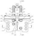
도 1은 본 발명의 2축 힌지 장치의 구성도이다.
도 2는 본 발명의 2축 힌지 장치의 회전 각도별 도면이다.
도 3은 본 발명의 결합 사시도이다.
도 4는 본 발명의 저면 결합 사시도이다.
도 5는 본 발명의 평면도이다.
도 6은 본 발명의 저면도이다.
도 7은 도 5에서 제1 회전판과 제2 회전판이 분리된 상태의 평면도이다.
도 8은 도 5의 A-A선 단면도이다.
도 9는 도 5의 B-B선 단면도이다.
도 10은 본 발명의 일부 분해 사시도이다.
도 11은 도 10으로부터 한쪽 회전 규제 수단을 분리한 상태의 분해 사시도이다.
도 12는 본 발명의 회전축의 사시도이다.
도 13은 본 발명의 힌지 장치에 마련된 스토퍼의 사시도이다.
도 14는 본 발명의 제1 회전축과 제2 회전축 및 이동 부재간의 결합 관계를 나타낸 도면이다.1 is a configuration diagram of a two-axis hinge device of the present invention.
2 is a view for each rotation angle of the two-axis hinge device of the present invention.
3 is a perspective view of the combination of the present invention.
Figure 4 is a perspective view of the bottom coupling of the present invention.
5 is a plan view of the present invention.
6 is a bottom view of the present invention.
FIG. 7 is a plan view of a state in which the first rotation plate and the second rotation plate are separated from each other in FIG. 5 .
8 is a cross-sectional view along line AA of FIG. 5 .
9 is a cross-sectional view along line BB of FIG. 5 .
10 is a partially exploded perspective view of the present invention.
Fig. 11 is an exploded perspective view of a state in which one rotation regulating means is separated from Fig. 10;
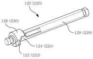
12 is a perspective view of a rotating shaft of the present invention.
13 is a perspective view of a stopper provided in the hinge device of the present invention.
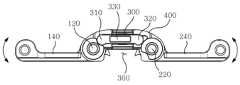
14 is a view showing the coupling relationship between the first rotation shaft and the second rotation shaft and the moving member according to the present invention.
도 1은 본 발명의 2축 힌지 장치를 나타낸 설명도이다. 도 1을 참조하면, 제1 회전축(10)과 제2 회전축(20)이 서로 간격을 두고 구비되고, 제1 회전축(10)과 제2 회전축(20)의 사이에 이동 가능한 이동 부재(30)가 구비되는 구조일 수 있다.1 is an explanatory view showing a two-axis hinge device of the present invention. Referring to FIG. 1, a first
제1 회전축(10)과 제2 회전축(20)의 사이에는 폴더블 디스플레이 패널(F)의 만곡부(F1)가 수용되는 수납 공간부(40)가 형성되도록 이동 부재(30)가 편심되게 설치될 수 있다. 즉, 이동 부재(30)는 제1 회전축(10)과 제2 회전축(20)의 중심선을 연결한 수평선상으로부터 이격된 위치에 편심되게 마련될 수 있다.The moving
다시 말해서, 이동 부재(30)는 폴더블 디스플레이 패널(F)로부터 멀어지는 방향으로 배열될 수 있다.In other words, the moving
제1 회전축(10)과 제2 회전축(20)은 각각 걸림홈(11)(21)이 형성되고, 이동 부재(30)의 양단부에는 걸림홈(11)(21)에 삽입되어 걸림이 이루어지는 걸림편(31)이 형성될 수 있다.The first
걸림홈(11)(21)의 위치는 제1 회전축(10)과 제2 회전축(20)의 중심(C1)(C2)으로부터 이격된 위치에 형성될 수 있다. 따라서, 편심되게 마련되는 이동 부재(30)는 도면상 수평 이동하면서 제1 회전축(10)의 걸림홈(11) 또는 제2 회전축(20)의 걸림홈(21)중 어느 한쪽에 걸림될 수 있다.The
제1 회전판(10)과 제2 회전축(20)에는 폴더블 디스플레이 패널(F)의 접힘 및 펼침 동작이 가능하도록 각각 제1 회전판(50)과 제2 회전판(60)이 갖추어질 수 있다.The first rotating
제1 회전축(10)과 제2 회전축(20)은 동시에 회전되지 않고 어느 한쪽의 회전축이 회전하면, 나머지 한쪽의 회전축은 이동 부재(30)의 걸림편(31)에 걸려서 정지된 상태일 수 있다.The first
이동 부재(30)는 제1 회전축(10)과 제2 회전축(20)의 회전시, 동시 회전되지 않고 각자 단독으로 회전 동작이 이루어지도록 제어하며, 제1 회전축(10)과 제2 회전축(20)의 중심(C1)(C2)을 연결한 수평선으로부터 이격된 위치에 배치됨에 따라 수납 공간부(40)가 형성되며, 이러한 수납 공간부(40)에는 폴더블 디스플레이 패널(F)의 접힘 동작시 형성되는 만곡부(F1)를 수용할 수 있다.When the
따라서, 본 발명은 예를 들어 여러 각도로 회전이 가능하고, 폴더블 디스플레이 패널(F)의 접힘 및 펼침 동작시 원활하게 동작이 이루어질 수 있다.Therefore, in the present invention, for example, rotation is possible at various angles, and operations can be performed smoothly during folding and unfolding operations of the foldable display panel F.
또한, 본 발명은 제1 회전축(10)과 제2 회전축(20)의 반경을 r이라고 할때, 제1 회전축(10)의 중심(C1)과 제2 회전축(20)의 중심(C2)간의 거리를 d, 제1 회전축(10)과 제2 회전축(10) 사이의 간격을 L이라고 할 때, L=d-2r이 될 수 있다.In addition, when the radius of the
제1 회전축(10)과 제2 회전축(20)의 반경 r이 커지면 그에 비례하여 수납 공간부(40)의 깊이(도면상 수직 방향 길이)도 증가할 수 있다.When the radii r of the first
도 2를 참조하면, (a)는 제1 회전축(10)과 제2 회전축(20)에 결합된 제1 회전판(50)과 제2 회전판(60)간의 각도가 0도인 경우로서, 닫힌 상태로 볼 수 있다.Referring to FIG. 2, (a) is a case where the angle between the first rotating
(b)는 (a) 상태인 0도로부터 제1 회전판(50)의 회전으로 90도 전환된 상태일 수 있다. 이때 제2 회전판(60)은 제2 회전축(20)의 걸림홈(21)안에 이동 부재(30)의 단부가 걸림된 상태이기 때문에 회전하지 못하고 정지된 상태일 수 있다.(b) may be a state in which 90 degrees are converted from 0 degrees, which is the state of (a), to rotation of the first
(c)는 (b) 상태에서 제2 회전판(60)의 회전으로 180도 펼쳐진 상태일 수 있다. 이때 제2 회전판(60)의 회전시, 제2 회전축(20)에서 걸림 상태의 이동 부재(30)는 제1 회전축(10)으로 밀려서 이동할 수 있고, 제1 회전축(10)의 걸림홈(11)안에 이동 부재(30)의 단부가 걸림될 수 있으며, 그에 따라 제1 회전축(10)은 회전되지 못하고 정지된 상태일 수 있다.(c) may be a state in which the second
(d)는 (c) 상태에서 제2 회전판(60)을 더 회전시킨 상태로서, (b)의 상태와 반대의 90도 각도로 회전된 상태가 될 수 있다.(d) is a state in which the second
(e)는 다시 0도 위치로 복귀시킨 상태로서, (c) 상태에서 제2 회전축(20)을 회전시켜서 걸림홈(21)이 이동 부재(30)의 단부가 삽입되는 위치로 변경한 다음, 제1 회전축(10)을 회전시키면, 제1 회전축(10)의 걸림홈(11)안에 걸려있던 이동 부재(30)는 제2 회전축(20) 방향으로 수평 이동하여 제2 회전축(20)의 걸림홈(21)안에 삽입되어 걸림된 상태가 될 수 있다.(e) is a state returned to the 0 degree position, and in (c), the second
그러나, 본 발명은 도 2에 도시된 제1 회전축(10), 제2 회전축(20), 이동 부재(30), 제1 회전판(50) 및 제2 회전판(60)간의 배치 구조에 한정되지 않고, 다양하게 제1 회전축(10) 및 제2 회전축(20)에 각각 결합되는 제1 회전판(50) 및 제2 회전판(60)의 결합 위치를 달리하고 접힘 및 펼침 동작을 구현할 수 있다.However, the present invention is not limited to the arrangement structure between the first
즉, 예를 들어 도 2에서 180도로 펼쳐진 상태를 (c)에 도시하였으나, 제1 회전축(10)의 걸림홈(11)에 이동 부재(30)의 걸림편(31)이 삽입되지 않고, 제2 회전축(20)의 걸림홈(21)에 이동 부재(30)의 걸림편(31)이 삽입되어 걸림된 상태로 배치할 수 있다. 이때, 제1 회전축(10)의 걸림홈(11)은 도 2의 (c) 상태에서 90도 시계방향으로 회전되어 하향 위치된 상태일 수 있다.That is, for example, although (c) shows a state unfolded at 180 degrees in FIG. 2, the locking
한편, 도 2의 (a)에만 폴더블 디스플레이 패널(F)을 도시하였지만, 나머지 (b) 내지 (e)에도 폴더블 디스플레이 패널(F)가 마련된 것으로서 설명의 편의상 생략한 것일 뿐이다.Meanwhile, although the foldable display panel F is shown only in (a) of FIG. 2 , the foldable display panel F is also provided in the remaining (b) to (e) and is omitted for convenience of explanation.
[실시 예][Example]
도 3은 본 발명의 결합 사시도, 도 4는 본 발명의 저면 결합 사시도, 도 5는 본 발명의 평면도, 도 6은 본 발명의 저면도이다.Figure 3 is a combined perspective view of the present invention, Figure 4 is a bottom combined perspective view of the present invention, Figure 5 is a plan view of the present invention, Figure 6 is a bottom view of the present invention.
도 3 내지 도 6을 참조하면, 본 발명의 2축 힌지 장치는 회전 가능하게 연결되고 서로 대칭되게 마련되는 제1 힌지 유니트(100)와 제2 힌지 유니트(200)를 포함하여 구성될 수 있다.Referring to FIGS. 3 to 6 , the two-axis hinge device of the present invention may include a
제1 힌지 유니트(100)와 제2 힌지 유니트(200)는 공통적으로 회전판, 회전판과 함께 회전하는 회전축, 회전축에 결합되는 아암, 회전축의 회전 각도를 규제하는 회전 규제 수단, 결합판과 연결되는 커넥터를 구비할 수 있다.The
구체적으로, 제1 힌지 유니트(100)는 제1 회전판(110), 제1 회전판(110)과 결합되어 회전되는 제1 회전축(120), 제1 회전축(120)상에 구비되는 제1 회전 규제 수단(130), 제1 회전축(120)의 회전에 의해 제1 회전판(110)이 회전되도록 연결되는 제1 아암(140)을 포함할 수 있다.Specifically, the
제2 힌지 유니트(200)는 제2 회전판(210), 제2 회전판(210)과 결합되어 회전되는 제2 회전축(220), 제2 회전축(220)상에 구비되는 제2 회전 규제 수단(230), 제2 회전축(220)의 회전에 의해 제2 회전판(210)이 회전되도록 연결되는 제2 아암(240)을 포함할 수 있다.The
또한, 제1 회전축(120)과 제2 회전축(220)은 서로 소정의 간격을 두고 배치될 수 있고, 제1 회전축(120)과 제2 회전축(220)의 사이에는 제1 회전축(120) 및 제2 회전축(220)의 회전시 서로간의 회전 동작을 제어해주는 이동 부재(300)가 구비될 수 있다.In addition, the first
제1 회전축(120)과 제2 회전축(220)의 사이를 연결하고 제1 회전축(120)과 제2 회전축(220)이 관통하여 연결되는 스토퍼(400)가 구비되고, 제1 아암(140)과 제2 아암(240)의 반대편에는 제1 회전 규제 수단(130)과 제2 회전 규제 수단(230) 사이에 연결되고 회전 규제 수단과 대면되면서 회전축의 회전 동작을 규제하는 캠 부재(500)가 마련될 수 있다. 캠부재(500)의 양측에는 후술하는 캠 슬라이더(131,231)과 대면되는 캠(510)(520)이 형성될 수 있다. 캠(510)(520)의 내부에는 제1 회전축(120)과 제2 회전축(220)이 관통될 수 있다.A
도 8을 참조하면, 회전 규제 수단(130,230)은 캠 부재(500)와 대면되면서 회전축(120,220)의 회전 각도를 규제해주는 캠 슬라이더(131,231), 탄성 부재(132,232) 및 간격 유지 부재(600)가 포함될 수 있다. 따라서, 제1 회전 규제 수단(130)에는 제1 캠 슬라이더(131), 제1 탄성 부재(132)를 포함할 수 있고, 제2 회전 규제 수단(230)에는 제2 캠 슬라이더(231), 제2 탄성 부재(232)를 포함할 수 있다.Referring to FIG. 8, the rotation regulating means 130 and 230 include
회전 규제 수단(130,230)은 모두 회전축(120,220)의 외주면에 결합될 수 있고, 캠 슬라이더(131,231)는 회전축(120,220)의 길이 방향을 따라 탄성 부재(132,232)를 압축하면서 슬라이딩 이동 가능하게 결합될 수 있다.All of the rotation control means 130 and 230 may be coupled to the outer circumferential surfaces of the
다시 말해서, 캠 부재(500)와 캠 슬라이더(131,231)은 서로 대면하는 부분에 원주 방향을 따라 간격을 두고 돌출된 돌기가 형성되고, 고정된 상태의 캠 부재(500)에 대하여 회전축(120,220)의 회전에 의해 캠 슬라이더(131,231)가 회전하면서 캠 부재(500)의 돌기와 캠 슬라이더(131,231)의 돌기가 서로 만나면 캠 슬라이더(131,231)는 회전축을 따라 탄성 부재를 압축하면서 이동하고, 캠 부재(500)의 돌기로부터 캠 슬라이더(131,231)의 돌기가 벗어나면 압축된 탄성 부재의 반발력에 의해 캠 슬라이더(131,231)의 돌기는 다시 캠 부재(500)의 돌기와 돌기 사이의 홈에 끼워지도록 슬라이딩 이동할 수 있다.In other words, the
회전 규제 수단(130,230)에는 캠 슬라이더(131,231) 및 탄성 부재(132,232)의 일단부에는 각각 체결 부재가 결합되어 고정될 수 있다. 체결 부재는 제1 체결 부재(150)와 제2 체결 부재(250)로 이루어지고, 제1 회전축(120) 및 제2 회전축(220)의 단부측에 끼워져서 고정된 상태를 유지할 수 있다.Fastening members may be coupled to and fixed to one end of the
제1 체결 부재(150) 및 제2 체결 부재(250)는 결합링, 스냅링, 고정 링 등으로 이루어질 수 있고, 간격 유지 부재(600)와 함께 제1 회전축(120) 및 제2 회전축(220)상에 고정된 상태로 결합될 수 있다. 따라서, 탄성 부재(132,232)는 체결 부재(150,250)에 의해 탄성 지지될 수 있다.The
또한, 제1 회전판(110)과 제2 회전판(210)의 저면에는 각각 원호형을 이루는 회전 돌기(112)(212)가 돌출되게 형성되고, 일측에는 장공이 형성된 이동 통로 부재(114)(214)가 형성될 수 있다.In addition, on the bottom surfaces of the first
또한, 제1 회전판(110)과 제2 회전판(210)의 하부에는 고정 브래킷(700)이 마련되고, 고정 브래킷(700)의 내부에는 제1 회전판(110)과 제2 회전판(210)의 회전 돌기(112)(212)가 삽입되어서 회전시 원호 동작으로 가이드해주는 가이드 부재(710)(720)가 마련될 수 있다.In addition, a fixing
도 9 내지 도 12를 참조하면, 가이드 부재(710)(720)는 각각 제1 회전판(110)과 제2 회전판(210)의 하부에 돌출된 회전 돌기(112)(212)가 삽입되어서 가이드되도록 원호형으로 형성되고, 간격을 두고 한쌍의 가이드 부재로 구비될 수 있다. 한쌍의 가이드 부재(710)(720)의 사이에 회전 돌기(112)(212)가 삽입되어서 제1 회전판(110)과 제2 회전판(210)의 회전시 가이드될 수 있다.Referring to FIGS. 9 to 12 , the
도 12를 참조하면, 제1 회전축(120)과 제2 회전축(220)의 일측 소정 위치에는 걸림홈인 제1 걸림홈(122)과 제2 걸림홈(222)이 형성되고, 제1 걸림홈(122)과 제2 걸림홈(222)의 안쪽 위치에는 회전 규제홈인 제1 회전 규제홈(124)과 제2 회전 규제홈(224)이 형성될 수 있다.Referring to FIG. 12, a
제1 회전축(120)과 제2 회전축(220)의 선단부에는 제1 아암(140)과 제2 아암(240)의 전방에서 걸림된 상태로 위치하도록 직경이 상대적으로 큰 돌출부인 제1 돌출부(126)와 제2 돌출부(226)가 형성될 수 있고, 이 돌출부(126,226)에 걸림홈(122,222) 및 회전 규제홈(124,224)이 형성될 수 있다.The
또한, 제1 회전축(120)과 제2 회전축(220)의 몸체부의 일부분, 구체적으로는 양측에는 각각 평탄면인 복수의 제1 평탄면(128)과 제2 평탄면(228)이 형성될 수 있다. 제1 회전축(120)과 제2 회전축(220)에 각각 형성된 제1 평탄면(128)과 제2 평탄면(228)은 제1 회전축(120)과 제2 회전축(220)이 관통하는 캠 슬라이더(131,231)의 결합공도 동일 구조의 평탄면이 형성된 장공 구조로 형성되어 결합되므로, 제1 회전축(120)과 제2 회전축(220)의 회전시 캠 슬라이더(131,231)도 동시에 회전되고, 캠 부재(500)의 캠(510,520)에 형성된 돌기에 의해 밀리면 제1 회전축(120)과 제2 회전축(220)의 길이 방향을 따라 슬라이딩 이동될 수 있다.In addition, a plurality of first
제1 아암(140)과 제2 아암(240)에는 각각 제1 회전판(110)과 제2 회전판(210)의 하부에 마련된 이동 통로부재(114)(214)에 삽입되는 걸림핀(142,242)이 구비될 수 있다.The
제1 회전축(120)과 제1 회전축(220)의 사이에 마련되는 이동 부재(300)의 양측에는, 각각 제1 회전축(120)과 제1 회전축(220)의 제1 돌출부(126) 및 제2 돌출부(226)에 대면되고 걸림홈인 제1 걸림홈(122) 및 제2 걸림홈(222)에 걸림이 이루어지는 걸림 돌기(310,320)가 형성될 수 있다.On both sides of the moving
도 14를 참조하면, 이동 부재(300)는 제1 회전축(120)과 제2 회전축(220)의 중심을 연결한 수평선으로부터 이격된 위치에 편심되게 마련되고, 수납 공간부(360)가 형성될 수 있다.Referring to FIG. 14 , the
제1 회전판(110) 또는 제2 회전판(210)의 회전시, 제1 회전축(120)의 제1 걸림홈(122)에 이동 부재(300)의 걸림돌기(310)가 삽입된 상태에서 제1 회전축(120) 이 회전하면, 제1 회전축(120)의 걸림돌기(310)가 회전 이동하면서 이동 부재(300)의 걸림돌기(310)를 밀게 되고, 이때 제1 회전축(220)의 제2 걸림홈(222)은 수평 이동하는 이동 부재(300)의 걸림돌기(320)가 삽입되는 위치의 회전 상태일 수 있다. 그에 따라 이동 부재(300)는 제1 회전축(220) 방향으로 수평 이동할 수 있다.When the
이동 부재(300)의 전면에는 이동 부재(300)가 지지되는 지지 부재(350)가 구비될 수 있다. 지지 부재(350)의 양측에는 제1 회전축(120)과 제2 회전축(220)의 단부에 끼워지는 결합공(351), 양쪽의 결합공(351) 사이에 형성되고 이동 부재(300)의 중앙에 돌출된 돌기부(330)가 도면상 회전축(110,210) 방향으로 이동가능하게 삽입되는 장공 구조의 삽입공(352)이 형성될 수 있다. 다시 말해서, 삽입공(352)은 돌기부(330)의 이동 방향 길이보다 길게 형성될 수 있다.A
제1 회전판(110) 및 제 2회전판(210)은 각각 회전시, 제1 회전판(110) 및 제2 회전판(210)이 서로 근접한 일단부가 회동될때, 서로 간섭되지 않고, 제1 회전판(110) 및 제2 회전판(210)의 일단부가 회동되는 방향으로 마련된 이동 부재(300), 스토퍼(400) 등에 걸리지 않게 배치될 수 있다. 본 발명은 제1 회전축(120)과 제2 회전축(220)의 중심으로부터 이격된 위치에 이동 부재(300)가 마련된 구조이므로, 이동 부재(300)의 후퇴에 따른 수납 공간부(360)가 확보되며, 수납 공간부(360)의 공간 크기에 의해 회전하는 제1 회전판(110)과 제2 회전판(210)의 일단부가 수납 공간부(360)안에 수용되므로, 아무런 간섭없이 회전 동작을 할 수 있다.When the first
도 13을 참조하면, 예를 들어 스토퍼(400)의 양측에는 제1 회전축(120)과 제1 회전축(220)의 제1 회전 규제홈(124) 및 제2 회전 규제홈(224)에 대면되면서 회전 각도를 제한해주는 걸림편(410)(420)이 돌출되게 형성될 수 있다.Referring to FIG. 13, for example, both sides of the
또한, 스토퍼(400)의 양측에는 제1 회전축(120)과 제1 회전축(220)이 관통되는 관통공(430)(432)이 형성될 수 있다.In addition, the first
다시 말해서, 제1 회전축(120)과 제1 회전축(220)의 회전시, 각각의 회전축은 360도 회전되지 않고 180도 범위내에서 회전될 수 있다. 따라서, 제1 회전축(120)과 제1 회전축(220)은 서로 접하는 상태의 각도를 0도라고 할때, 각각 서로멀어지는 방향으로 180도 까지 회전되면서 서로 접할 수 있다.In other words, when the
본 발명의 실시 예에 있어서, 구체적으로 도시하지는 않았으나 2축 힌지 장치의 하부를 덮는 케이스가 마련될 수 있거나 또는 노트북에 설치되는 경우에는 제1 회전판과 제2 회전판은 각각 노트북의 화면부와 본체부에 결합되고, 나머지 부분은 케이스안에 구비될 수 있다.In an embodiment of the present invention, although not specifically shown, a case covering the lower portion of the two-axis hinge device may be provided, or when installed in a notebook, the first rotation plate and the second rotation plate are the screen portion and the main body portion of the notebook, respectively. coupled to, and the remaining parts may be provided in the case.
또한, 본 발명은 폴더블 디스플레이 패널이 구비된 경우, 접힘 동작시 제1 회전축(120)과 제1 회전축(220)의 사이에 공간이 마련되어 있으므로, 폴더블 디스플레이 패널의 만곡부가 아무 간섭없이 수용될 수 있다.In addition, in the present invention, when a foldable display panel is provided, since a space is provided between the first
따라서, 본 발명의 2축 힌지 장치는 노트북과 같이 화면부와 본체부가 분할된 구조는 물론, 폴더블 디스플레이 패널이 구비된 폴더블 폰과 같은 휴대용 단말기 등에 적합하게 장착하여 사용될 수 있다.Therefore, the two-axis hinge device of the present invention can be suitably mounted and used in a portable terminal such as a foldable phone equipped with a foldable display panel as well as a structure in which a screen portion and a body portion are divided like a laptop computer.
10... 제1 회전축11,21... 걸림홈
20... 제2 회전축30... 이동 부재
31... 걸림편40... 수납 공간부
50... 제1 회전판60... 제2 회전판
100... 제1 힌지 유니트110... 제1 회전판
112,212... 회전 돌기114,214... 이동 통로 부재
120... 제1 회전축122... 제1 걸림홈
124... 제1 회전 규제홈126... 제1 돌출부
128... 제1 평탄면
130... 제1 회전 규제 수단131... 제1 캠 슬라이더
132... 제1 탄성 부재
140.... 제1 아암142,242... 걸림핀
150... 제1 체결 부재
200... 제2 힌지 유니트210... 제2 회전판
220... 제2 회전축222... 제2 걸림홈
224... 제2 회전 규제홈226... 제2 돌출부
228... 제2 평탄면
230... 제2 회전 규제 수단231... 제2 캠 슬라이더
232... 제2 탄성 부재240... 제2 아암
250... 제2 체결 부재
300... 록킹 부재310,320... 걸림 돌기
330... 돌기부350... 지지 부재
351... 결합공352... 삽입공
360... 수납 공간부
400... 스토퍼410,420... 걸림편
430,432... 관통공500... 캠 부재
510,520... 캠600... 간격 유지 부재
700... 고정 브래킷710,720... 가이드 부재
C1,C2... 중심10... 1st
20... second
31 ...
50... 1st
100...
112,212... rotating protrusion 114,214... moving passage member
120...
124... first
128... first flat surface
130... first rotation regulating means 131... first cam slider
132... first elastic member
140... first arm 142,242... locking pin
150... first fastening member
200...
220... 2nd
224... second
228... second flat surface
230... second rotation regulating means 231... second cam slider
232... second
250 ... second fastening member
300... locking
330...
351...
360 ... Storage space part
400...
430,432... through
510,520...
700... fixing bracket 710,720... guide element
C1,C2... center
Claims (10)
Translated fromKorean상기 제1 힌지 유니트의 맞은편에 이격되게 구비되고 회전하는 제2 회전축을 구비하는 제2 힌지 유니트;
상기 제1 힌지 유니트의 제1 회전축과 상기 제2 힌지 유니트의 제2 회전축의 사이에 마련되고, 상기 제1 회전축 또는 상기 제2 회전축의 회전에 의해 상기 제1 회전축 또는 상기 제2 회전축에 걸림되어 회전 상태를 제어하도록 이동하는 이동 부재; 를 포함하고,
상기 제1 힌지 유니트와 상기 제2 힌지 유니트는 상기 이동 부재가 상기 제1 회전축 또는 상기 제2 회전축에 걸림되게 이동함에 따라 서로 독립되게 회전되며,
상기 이동 부재는 수납 공간부가 형성되도록 상기 제1 회전축과 제2 회전축의 중심선상으로부터 이격된 위치에 배치되는 힌지 장치.
A first hinge unit having a rotating first rotation shaft;
a second hinge unit spaced apart from the first hinge unit and having a rotating second rotation shaft;
It is provided between the first rotational shaft of the first hinge unit and the second rotational shaft of the second hinge unit, and is caught on the first rotational shaft or the second rotational shaft by rotation of the first rotational shaft or the second rotational shaft. a moving member that moves to control a rotational state; including,
The first hinge unit and the second hinge unit are rotated independently of each other as the moving member is moved to be caught on the first rotation shaft or the second rotation shaft,
The hinge device is disposed at a position spaced apart from the center line of the first rotation shaft and the second rotation shaft to form an accommodation space.
상기 제1 힌지 유니트와 제2 힌지 유니트는 각각 상기 제1 회전축과 제2 회전축과 결합되어 회전되는 제1 회전판 및 제2 회전판이 마련되고,
상기 제1 회전판 및 제2 회전판의 일면에는 폴더블 디스플레이 패널이 구비되며,
상기 제1 회전판 또는 상기 제2 회전판의 회전에 의해 상기 폴더블 디스플레이 패널은 접힘 및 펼침 동작이 이루어지고,
상기 폴더블 디스플레이 패널의 접힘 동작시, 만곡부는 상기 수납 공간부에 수용되는 힌지 장치.
According to claim 1,
The first hinge unit and the second hinge unit are provided with a first rotation plate and a second rotation plate rotated by being coupled to the first rotation shaft and the second rotation shaft, respectively,
A foldable display panel is provided on one surface of the first rotation plate and the second rotation plate,
The foldable display panel is folded and unfolded by rotation of the first rotating plate or the second rotating plate,
The hinge device of claim 1 , wherein the curved portion is accommodated in the storage space portion during a folding operation of the foldable display panel.
상기 제1 힌지 유니트와 제2 힌지 유니트는 각각 상기 제1 회전축과 제2 회전축과 결합되어 회전되는 제1 회전판 및 제2 회전판이 마련되고,
상기 제1 회전축이 회전하면, 상기 이동 부재의 걸림편에 의해 제2 회전축은 정지한 상태이며,
상기 제2 회전축이 회전하면 상기 이동 부재는 상기 제1 회전축 방향으로 이동하여 상기 제1 회전축의 회전 동작이 정지되고,
상기 제1 회전축 및 제2 회전축의 회전 동작에 의해 상기 제1 회전판 및 제2 회전판은 복수의 각도로 변화되는 힌지 장치.
According to claim 1,
The first hinge unit and the second hinge unit are provided with a first rotation plate and a second rotation plate rotated by being coupled to the first rotation shaft and the second rotation shaft, respectively,
When the first rotational shaft rotates, the second rotational shaft is stopped by the engaging piece of the moving member,
When the second rotational shaft rotates, the moving member moves in the direction of the first rotational shaft to stop the rotational operation of the first rotational shaft;
The hinge device wherein the first rotation plate and the second rotation plate are changed at a plurality of angles by the rotational operation of the first rotation shaft and the second rotation shaft.
상기 제1 힌지 유니트와 제2 힌지 유니트는,
상기 제1 회전축과 제2 회전축의 회전시 회전 각도를 규제해주는 회전 규제 수단이 구비되고,
상기 회전 규제 수단은 상기 제1 회전축과 제2 회전축상에 결합되는 캠 부재, 상기 캠 부재와 대면되고 상기 제1 회전축과 제2 회전축과 동시에 회전되면서 슬라이딩 이동 가능하게 결합되는 캠 슬라이더, 캠 슬라이더의 일면에 탄지되는 탄성 부재를 포함하는 힌지 장치.
According to claim 1,
The first hinge unit and the second hinge unit,
A rotation regulating means is provided for regulating a rotation angle when the first rotation shaft and the second rotation shaft rotate,
The rotation regulating means includes a cam member coupled to the first rotational shaft and the second rotational shaft, a cam slider facing the cam member and being slidably coupled while rotating simultaneously with the first rotational shaft and the second rotational shaft, and a cam slider. A hinge device comprising an elastic member supported on one surface.
상기 제1 회전축과 제2 회전축의 단부측에는 상기 이동 부재의 양 단부에 형성된 걸림편이 상기 제1 회전축 또는 제2 회전축의 회전에 따라 상기 제1 회전축 또는 상기 제2 회전축 방향으로 이동하여 걸림되는 걸림홈이 각각 형성되는 힌지 장치.
According to claim 1,
At the ends of the first rotation shaft and the second rotation shaft, locking pieces formed at both ends of the movable member are moved in the direction of the first rotation shaft or the second rotation shaft according to the rotation of the first rotation shaft or the second rotation shaft, and the locking groove is engaged. Hinge devices are formed respectively.
상기 제1 회전축과 제2 회전축의 단부측에는 상기 이동 부재의 양 단부에 형성된 걸림편이 상기 제1 회전축 또는 제2 회전축의 회전에 따라 상기 제1 회전축 또는 상기 제2 회전축 방향으로 이동하여 걸림되는 걸림홈이 각각 형성되고,
상기 걸림홈은 상기 제1 회전축과 제2 회전축의 중심으로부터 이격된 위치에 편심되게 형성되며,
상기 이동 부재의 걸림편은 상기 제1 회전축 또는 제2 회전축 방향으로 이동하면서 상기 걸림홈중 어느 한쪽에 걸림되는 힌지 장치.
According to claim 1,
At the ends of the first rotation shaft and the second rotation shaft, locking pieces formed at both ends of the movable member are moved in the direction of the first rotation shaft or the second rotation shaft according to the rotation of the first rotation shaft or the second rotation shaft, and the locking groove is engaged. are formed, respectively,
The locking groove is formed eccentrically at a position spaced apart from the center of the first rotation shaft and the second rotation shaft,
The hinge device of claim 1 , wherein the engaging piece of the movable member is engaged in one of the engaging grooves while moving in the direction of the first rotational axis or the second rotational axis.
상기 제1 회전판과 제2 회전판의 하부에는 상기 제1 회전축과 제2 회전축에 결합되는 아암이 각각 마련되고,
상기 아암에는 상기 제1 회전판과 제2 회전판의 하부에 형성된 이동 통로 부재에 결합되는 걸림핀이 마련되는 힌지 장치.
According to claim 2,
Arms coupled to the first rotational shaft and the second rotational shaft are respectively provided below the first rotational plate and the second rotational plate,
The arm is provided with a locking pin coupled to a moving passage member formed below the first and second rotation plates.
상기 제1 회전축과 제2 회전축의 단부에는 각각 회전 규제홈이 형성되며,
상기 제1 회전축과 제2 회전축의 사이에는 상기 회전 규제홈과 대면되는 걸림편이 양측에 형성된 스토퍼가 고정되며,
상기 제1 회전축 또는 상기 제2 회전축의 회전시 상기 스토퍼의 걸림편에 상기 제1 회전축 또는 상기 제2 회전축의 상기 회전 규제홈이 걸려서 정지되는 힌지 장치.
According to claim 1,
Rotation regulating grooves are formed at ends of the first rotation shaft and the second rotation shaft, respectively,
A stopper having locking pieces facing the rotation regulating groove on both sides is fixed between the first rotation shaft and the second rotation shaft,
A hinge device in which the rotation regulating groove of the first rotation shaft or the second rotation shaft is caught and stopped by the locking piece of the stopper when the first rotation shaft or the second rotation shaft rotates.
상기 제1 회전축과 제2 회전축에 형성되는 상기 회전 규제홈은,
상기 제1 회전축과 제2 회전축에 각각 결합되는 제1 회전판과 제2 회전판의 접힘 및 펼침 동작시 회전 각도를 제한하는 힌지 장치.
According to claim 8,
The rotation regulating groove formed on the first rotation shaft and the second rotation shaft,
A hinge device for limiting rotational angles during folding and unfolding operations of the first rotation plate and the second rotation plate coupled to the first rotation shaft and the second rotation shaft, respectively.
상기 제1 회전축과 제2 회전축에는 각각 제1 회전판과 제2 회전판이 함께 회전되도록 결합되고,
상기 제1 회전판과 제2 회전판의 저면에는 제1 회전판과 제2 회전판의 회전 동작이 가이드하는 원호형의 회전 돌기가 형성되며,
상기 회전 돌기는 상기 제1 회전판과 제2 회전판의 하부에 고정되는 가이드 부재에 대면되고 원호 동작으로 가이드되는 힌지 장치.According to claim 1,
The first rotating shaft and the second rotating shaft are coupled so that the first rotating plate and the second rotating plate are rotated together, respectively,
Arc-shaped rotating protrusions are formed on the bottom surfaces of the first rotating plate and the second rotating plate to guide rotational motions of the first rotating plate and the second rotating plate,
The hinge device of claim 1, wherein the rotating protrusion faces a guide member fixed to lower portions of the first rotating plate and the second rotating plate and is guided in an arc motion.
Priority Applications (2)
| Application Number | Priority Date | Filing Date | Title |
|---|---|---|---|
| KR1020210017793AKR102547956B1 (en) | 2021-02-08 | 2021-02-08 | Biaxial Hinge Apparatus |
| CN202220089788.8UCN217234111U (en) | 2021-02-08 | 2022-01-13 | Double-shaft hinge device |
Applications Claiming Priority (1)
| Application Number | Priority Date | Filing Date | Title |
|---|---|---|---|
| KR1020210017793AKR102547956B1 (en) | 2021-02-08 | 2021-02-08 | Biaxial Hinge Apparatus |
Publications (2)
| Publication Number | Publication Date |
|---|---|
| KR20220114371A KR20220114371A (en) | 2022-08-17 |
| KR102547956B1true KR102547956B1 (en) | 2023-06-27 |
Family
ID=82829625
Family Applications (1)
| Application Number | Title | Priority Date | Filing Date |
|---|---|---|---|
| KR1020210017793AActiveKR102547956B1 (en) | 2021-02-08 | 2021-02-08 | Biaxial Hinge Apparatus |
Country Status (2)
| Country | Link |
|---|---|
| KR (1) | KR102547956B1 (en) |
| CN (1) | CN217234111U (en) |
Families Citing this family (1)
| Publication number | Priority date | Publication date | Assignee | Title |
|---|---|---|---|---|
| WO2024048968A1 (en)* | 2022-09-02 | 2024-03-07 | 삼성전자 주식회사 | Hinge structure and electronic device comprising same |
Citations (2)
| Publication number | Priority date | Publication date | Assignee | Title |
|---|---|---|---|---|
| CN102693683A (en) | 2011-03-21 | 2012-09-26 | 纬创资通股份有限公司 | Display device |
| US20130021762A1 (en) | 2011-07-11 | 2013-01-24 | Polymer Vision B.V. | Flexible display with display support |
Family Cites Families (4)
| Publication number | Priority date | Publication date | Assignee | Title |
|---|---|---|---|---|
| JPS6319694Y2 (en) | 1980-06-10 | 1988-06-01 | ||
| KR101875855B1 (en)* | 2014-02-17 | 2018-07-06 | 삼성전자주식회사 | Hinge apparatus and foldable display apparatus having the same |
| KR102062240B1 (en)* | 2018-06-20 | 2020-03-02 | (주)파인테크닉스 | Hinge appratus for flexible liquid crystal and terminal with the same |
| KR102310162B1 (en)* | 2019-07-23 | 2021-10-08 | 주식회사 에스코넥 | Hinge Apparatus And Foldable Display Apparatus Having The Same |
- 2021
- 2021-02-08KRKR1020210017793Apatent/KR102547956B1/enactiveActive
- 2022
- 2022-01-13CNCN202220089788.8Upatent/CN217234111U/enactiveActive
Patent Citations (2)
| Publication number | Priority date | Publication date | Assignee | Title |
|---|---|---|---|---|
| CN102693683A (en) | 2011-03-21 | 2012-09-26 | 纬创资通股份有限公司 | Display device |
| US20130021762A1 (en) | 2011-07-11 | 2013-01-24 | Polymer Vision B.V. | Flexible display with display support |
Also Published As
| Publication number | Publication date |
|---|---|
| CN217234111U (en) | 2022-08-19 |
| KR20220114371A (en) | 2022-08-17 |
Similar Documents
| Publication | Publication Date | Title |
|---|---|---|
| RU2382864C1 (en) | Pull-out module fixed on hinges and pull-out device, where it is used | |
| CN108286860B (en) | Refrigerator with a door | |
| KR102114080B1 (en) | Folding Hinge Apparatus and Electronic Device having it | |
| JP7223402B2 (en) | MULTI-AXIS HINGE DEVICE AND ELECTRONIC DEVICE USING THIS MULTI-AXIS HINGE DEVICE | |
| JP4731539B2 (en) | Hinge mechanism | |
| US8520377B2 (en) | Electronic device adjustable display member | |
| US5937062A (en) | Hinge module for mounting a flip onto a portable telephone set | |
| EP2581613A1 (en) | Hinge device | |
| EP2131559B1 (en) | Mechanisum for sliding casing, slidable casing and mobile phone using the same | |
| KR102298726B1 (en) | Folding hinge module for mobile terminal | |
| KR102432149B1 (en) | Hinge Apparatus and Electronic Device having it | |
| CN108286862B (en) | Embedded hinge device | |
| KR102547956B1 (en) | Biaxial Hinge Apparatus | |
| US20210151857A1 (en) | Portable electronic device | |
| JP2013100900A (en) | Biaxial hinge device | |
| CN115059681A (en) | Hinge components and end products | |
| CN113027899A (en) | Synchronous hinge | |
| KR100998942B1 (en) | Portable electronic devices and sliding / rotating switch modules and parts for them | |
| CN115263904A (en) | Rotating structure and electronic equipment | |
| CN114542583A (en) | Locking Mechanisms and Folding Electronics | |
| KR100984896B1 (en) | Mobile device hinges and mobile devices | |
| CN108204180B (en) | Embedded hinge device | |
| EP3922001B1 (en) | Slidable hinge mechanism and foldable device having same | |
| JP2009068550A (en) | Hinge structure of foldable portable electronic equipment | |
| US12360575B2 (en) | Dual axis slider hinge |
Legal Events
| Date | Code | Title | Description |
|---|---|---|---|
| PA0109 | Patent application | St.27 status event code:A-0-1-A10-A12-nap-PA0109 | |
| PA0201 | Request for examination | St.27 status event code:A-1-2-D10-D11-exm-PA0201 | |
| D13-X000 | Search requested | St.27 status event code:A-1-2-D10-D13-srh-X000 | |
| D14-X000 | Search report completed | St.27 status event code:A-1-2-D10-D14-srh-X000 | |
| PG1501 | Laying open of application | St.27 status event code:A-1-1-Q10-Q12-nap-PG1501 | |
| E902 | Notification of reason for refusal | ||
| PE0902 | Notice of grounds for rejection | St.27 status event code:A-1-2-D10-D21-exm-PE0902 | |
| P11-X000 | Amendment of application requested | St.27 status event code:A-2-2-P10-P11-nap-X000 | |
| P13-X000 | Application amended | St.27 status event code:A-2-2-P10-P13-nap-X000 | |
| E701 | Decision to grant or registration of patent right | ||
| PE0701 | Decision of registration | St.27 status event code:A-1-2-D10-D22-exm-PE0701 | |
| PR0701 | Registration of establishment | St.27 status event code:A-2-4-F10-F11-exm-PR0701 | |
| PR1002 | Payment of registration fee | St.27 status event code:A-2-2-U10-U11-oth-PR1002 Fee payment year number:1 | |
| PG1601 | Publication of registration | St.27 status event code:A-4-4-Q10-Q13-nap-PG1601 |