KR102543222B1 - Method and apparatus for transmitting and receiving signal with non-orthogonal multiple access in wirelss communication system - Google Patents
Method and apparatus for transmitting and receiving signal with non-orthogonal multiple access in wirelss communication systemDownload PDFInfo
- Publication number
- KR102543222B1 KR102543222B1KR1020180133410AKR20180133410AKR102543222B1KR 102543222 B1KR102543222 B1KR 102543222B1KR 1020180133410 AKR1020180133410 AKR 1020180133410AKR 20180133410 AKR20180133410 AKR 20180133410AKR 102543222 B1KR102543222 B1KR 102543222B1
- Authority
- KR
- South Korea
- Prior art keywords
- terminal
- base station
- transmission
- access
- rrc
- Prior art date
- Legal status (The legal status is an assumption and is not a legal conclusion. Google has not performed a legal analysis and makes no representation as to the accuracy of the status listed.)
- Active
Links
Images


Classifications
- H—ELECTRICITY
- H04—ELECTRIC COMMUNICATION TECHNIQUE
- H04W—WIRELESS COMMUNICATION NETWORKS
- H04W74/00—Wireless channel access
- H04W74/08—Non-scheduled access, e.g. ALOHA
- H04W74/0833—Random access procedures, e.g. with 4-step access
- H04W74/0841—Random access procedures, e.g. with 4-step access with collision treatment
- H—ELECTRICITY
- H04—ELECTRIC COMMUNICATION TECHNIQUE
- H04W—WIRELESS COMMUNICATION NETWORKS
- H04W76/00—Connection management
- H04W76/30—Connection release
- H—ELECTRICITY
- H04—ELECTRIC COMMUNICATION TECHNIQUE
- H04W—WIRELESS COMMUNICATION NETWORKS
- H04W72/00—Local resource management
- H04W72/20—Control channels or signalling for resource management
- H—ELECTRICITY
- H04—ELECTRIC COMMUNICATION TECHNIQUE
- H04J—MULTIPLEX COMMUNICATION
- H04J99/00—Subject matter not provided for in other groups of this subclass
- H—ELECTRICITY
- H04—ELECTRIC COMMUNICATION TECHNIQUE
- H04W—WIRELESS COMMUNICATION NETWORKS
- H04W72/00—Local resource management
- H04W72/04—Wireless resource allocation
- H04W72/044—Wireless resource allocation based on the type of the allocated resource
- H—ELECTRICITY
- H04—ELECTRIC COMMUNICATION TECHNIQUE
- H04W—WIRELESS COMMUNICATION NETWORKS
- H04W72/00—Local resource management
- H04W72/12—Wireless traffic scheduling
- H04W72/1263—Mapping of traffic onto schedule, e.g. scheduled allocation or multiplexing of flows
- H—ELECTRICITY
- H04—ELECTRIC COMMUNICATION TECHNIQUE
- H04W—WIRELESS COMMUNICATION NETWORKS
- H04W74/00—Wireless channel access
- H04W74/002—Transmission of channel access control information
- H04W74/004—Transmission of channel access control information in the uplink, i.e. towards network
- H—ELECTRICITY
- H04—ELECTRIC COMMUNICATION TECHNIQUE
- H04W—WIRELESS COMMUNICATION NETWORKS
- H04W74/00—Wireless channel access
- H04W74/08—Non-scheduled access, e.g. ALOHA
- H04W74/0833—Random access procedures, e.g. with 4-step access
- H—ELECTRICITY
- H04—ELECTRIC COMMUNICATION TECHNIQUE
- H04W—WIRELESS COMMUNICATION NETWORKS
- H04W76/00—Connection management
- H04W76/20—Manipulation of established connections
- H—ELECTRICITY
- H04—ELECTRIC COMMUNICATION TECHNIQUE
- H04W—WIRELESS COMMUNICATION NETWORKS
- H04W76/00—Connection management
- H04W76/20—Manipulation of established connections
- H04W76/27—Transitions between radio resource control [RRC] states
- H—ELECTRICITY
- H04—ELECTRIC COMMUNICATION TECHNIQUE
- H04L—TRANSMISSION OF DIGITAL INFORMATION, e.g. TELEGRAPHIC COMMUNICATION
- H04L5/00—Arrangements affording multiple use of the transmission path
- H04L5/003—Arrangements for allocating sub-channels of the transmission path
- H04L5/0048—Allocation of pilot signals, i.e. of signals known to the receiver
- H04L5/0051—Allocation of pilot signals, i.e. of signals known to the receiver of dedicated pilots, i.e. pilots destined for a single user or terminal
- H—ELECTRICITY
- H04—ELECTRIC COMMUNICATION TECHNIQUE
- H04L—TRANSMISSION OF DIGITAL INFORMATION, e.g. TELEGRAPHIC COMMUNICATION
- H04L5/00—Arrangements affording multiple use of the transmission path
- H04L5/003—Arrangements for allocating sub-channels of the transmission path
- H04L5/0053—Allocation of signalling, i.e. of overhead other than pilot signals
- H—ELECTRICITY
- H04—ELECTRIC COMMUNICATION TECHNIQUE
- H04W—WIRELESS COMMUNICATION NETWORKS
- H04W74/00—Wireless channel access
- H04W74/002—Transmission of channel access control information
- H—ELECTRICITY
- H04—ELECTRIC COMMUNICATION TECHNIQUE
- H04W—WIRELESS COMMUNICATION NETWORKS
- H04W74/00—Wireless channel access
- H04W74/08—Non-scheduled access, e.g. ALOHA
- H04W74/0833—Random access procedures, e.g. with 4-step access
- H04W74/0836—Random access procedures, e.g. with 4-step access with 2-step access
- H—ELECTRICITY
- H04—ELECTRIC COMMUNICATION TECHNIQUE
- H04W—WIRELESS COMMUNICATION NETWORKS
- H04W74/00—Wireless channel access
- H04W74/08—Non-scheduled access, e.g. ALOHA
- H04W74/0833—Random access procedures, e.g. with 4-step access
- H04W74/0838—Random access procedures, e.g. with 4-step access using contention-free random access [CFRA]
Landscapes
- Engineering & Computer Science (AREA)
- Computer Networks & Wireless Communication (AREA)
- Signal Processing (AREA)
- Mobile Radio Communication Systems (AREA)
Abstract
Translated fromKoreanDescription
Translated fromKorean본 개시는 무선 통신 시스템에서 비직교 다중접속(Non-Orthogonal Multiple Access, NOMA) 지원을 위한 신호 송수신 방법을 제안한다.The present disclosure proposes a signal transmission/reception method for supporting Non-Orthogonal Multiple Access (NOMA) in a wireless communication system.
4G 통신 시스템 상용화 이후 증가 추세에 있는 무선 데이터 트래픽 수요를 충족시키기 위해, 개선된 5G 통신 시스템 또는 pre-5G 통신 시스템을 개발하기 위한 노력이 이루어지고 있다. 이러한 이유로, 5G 통신 시스템 또는 pre-5G 통신 시스템은 4G 네트워크 이후 (Beyond 4G Network) 통신 시스템 또는 LTE 시스템 이후 (Post LTE) 이후의 시스템이라 불리어지고 있다. 높은 데이터 전송률을 달성하기 위해, 5G 통신 시스템은 초고주파(mmWave) 대역 (예를 들어, 60기가(80GHz) 대역과 같은)에서의 구현이 고려되고 있다. 초고주파 대역에서의 전파의 경로손실 완화 및 전파의 전달 거리를 증가시키기 위해, 5G 통신 시스템에서는 빔포밍(beamforming), 거대 배열 다중 입출력(massive MIMO), 전차원 다중입출력(Full Dimensional MIMO: FD-MIMO), 어레이 안테나(array antenna), 아날로그 빔형성(analog beam-forming), 및 대규모 안테나 (large scale antenna) 기술들이 논의되고 있다. 또한 시스템의 네트워크 개선을 위해, 5G 통신 시스템에서는 진화된 소형 셀, 개선된 소형 셀 (advanced small cell), 클라우드 무선 액세스 네트워크 (cloud radio access network: cloud RAN), 초고밀도 네트워크 (ultra-dense network), 기기 간 통신 (Device to Device communication: D2D), 무선 백홀 (wireless backhaul), 이동 네트워크 (moving network), 협력 통신 (cooperative communication), CoMP (Coordinated Multi-Points), 및 수신 간섭제거 (interference cancellation) 등의 기술 개발이 이루어지고 있다. 이 밖에도, 5G 시스템에서는 진보된 코딩 변조(Advanced Coding Modulation: ACM) 방식인 FQAM (Hybrid FSK and QAM Modulation) 및 SWSC (Sliding Window Superposition Coding)과, 진보된 접속 기술인 FBMC(Filter Bank Multi Carrier), NOMA(non-orthogonal multiple access), 및 SCMA(sparse code multiple access) 등이 개발되고 있다.Efforts are being made to develop an improved 5G communication system or pre-5G communication system to meet the growing demand for wireless data traffic after the commercialization of the 4G communication system. For this reason, the 5G communication system or pre-5G communication system is being called a system after a 4G network (Beyond 4G Network) communication system or an LTE system (Post LTE). In order to achieve a high data rate, the 5G communication system is being considered for implementation in a mmWave band (eg, 60 gigabytes (80 GHz) band). In order to mitigate the path loss of radio waves and increase the propagation distance of radio waves in the ultra-high frequency band, beamforming, massive MIMO, and Full Dimensional MIMO (FD-MIMO) are used in 5G communication systems. ), array antenna, analog beam-forming, and large scale antenna technologies are being discussed. In addition, to improve the network of the system, in the 5G communication system, an evolved small cell, an advanced small cell, a cloud radio access network (cloud RAN), and an ultra-dense network , Device to Device communication (D2D), wireless backhaul, moving network, cooperative communication, Coordinated Multi-Points (CoMP), and interference cancellation etc. are being developed. In addition, in the 5G system, advanced coding modulation (Advanced Coding Modulation: ACM) methods FQAM (Hybrid FSK and QAM Modulation) and SWSC (Sliding Window Superposition Coding), advanced access technologies FBMC (Filter Bank Multi Carrier), NOMA (non-orthogonal multiple access), SCMA (sparse code multiple access), and the like are being developed.
한편, 인터넷은 인간이 정보를 생성하고 소비하는 인간 중심의 연결 망에서, 사물 등 분산된 구성 요소들 간에 정보를 주고 받아 처리하는 IoT(Internet of Things, 사물인터넷) 망으로 진화하고 있다. 클라우드 서버 등과의 연결을 통한 빅데이터(Big data) 처리 기술 등이 IoT 기술에 결합된 IoE (Internet of Everything) 기술도 대두되고 있다. IoT를 구현하기 위해서, 센싱 기술, 유무선 통신 및 네트워크 인프라, 서비스 인터페이스 기술, 및 보안 기술과 같은 기술 요소 들이 요구되어, 최근에는 사물간의 연결을 위한 센서 네트워크(sensor network), 사물 통신(Machine to Machine, M2M), MTC(Machine Type Communication)등의 기술이 연구되고 있다. IoT 환경에서는 연결된 사물들에서 생성된 데이터를 수집, 분석하여 인간의 삶에 새로운 가치를 창출하는 지능형 IT(Internet Technology) 서비스가 제공될 수 있다. IoT는 기존의 IT(information technology)기술과 다양한 산업 간의 융합 및 복합을 통하여 스마트홈, 스마트 빌딩, 스마트 시티, 스마트 카 또는 커넥티드 카, 스마트 그리드, 헬스 케어, 스마트 가전, 첨단의료서비스 등의 분야에 응용될 수 있다.On the other hand, the Internet is evolving from a human-centered connection network in which humans create and consume information to an Internet of Things (IoT) network in which information is exchanged and processed between distributed components such as things. IoE (Internet of Everything) technology, which combines IoT technology with big data processing technology through connection with a cloud server, etc., is also emerging. In order to implement IoT, technical elements such as sensing technology, wired/wireless communication and network infrastructure, service interface technology, and security technology are required, and recently, sensor networks for connection between objects and machine to machine , M2M), and MTC (Machine Type Communication) technologies are being studied. In the IoT environment, intelligent IT (Internet Technology) services that create new values in human life by collecting and analyzing data generated from connected objects can be provided. IoT is a field of smart home, smart building, smart city, smart car or connected car, smart grid, health care, smart home appliances, advanced medical service, etc. can be applied to
이에, 5G 통신 시스템을 IoT 망에 적용하기 위한 다양한 시도들이 이루어지고 있다. 예를 들어, 센서 네트워크(sensor network), 사물 통신(Machine to Machine, M2M), MTC(Machine Type Communication)등의 기술이 5G 통신 기술인 빔 포밍, MIMO 및 어레이 안테나 등의 기법에 의해 구현되고 있는 것이다. 앞서 설명한 빅데이터 처리 기술로써 클라우드 무선 액세스 네트워크(cloud RAN)가 적용되는 것도 3eG 기술과 IoT 기술 융합의 일 예라고 할 수 있을 것이다.Accordingly, various attempts are being made to apply the 5G communication system to the IoT network. For example, technologies such as sensor network, machine to machine (M2M), and machine type communication (MTC) are implemented by techniques such as beamforming, MIMO, and array antenna, which are 5G communication technologies. . The application of the cloud radio access network (cloud RAN) as the big data processing technology described above can be said to be an example of convergence of 3eG technology and IoT technology.
상술한 것과 무선통신 시스템의 발전에 따라 다양한 서비스를 제공할 수 있게 됨으로써, 이러한 서비스들을 원활하게 제공하기 위한 방안이 요구되고 있다.As various services can be provided according to the above and the development of wireless communication systems, a method for smoothly providing these services is required.
본 개시는 무선 통신 시스템에서 비직교 다중접속(Non-Orthogonal Multiple Access, NOMA) 지원을 위한 신호 송수신 방법 및 장치를 제안한다.The present disclosure proposes a signal transmission/reception method and apparatus for supporting Non-Orthogonal Multiple Access (NOMA) in a wireless communication system.
본 개시는 무선 통신 시스템에서 제어 신호 처리 방법에 있어서, 기지국으로부터 전송되는 제1 제어 신호를 수신하는 단계; 상기 수신된 제1 제어 신호를 처리하는 단계; 및 상기 처리에 기반하여 생성된 제2 제어 신호를 상기 기지국으로 전송하는 단계를 포함하는 것을 특징으로 한다.The present disclosure provides a control signal processing method in a wireless communication system, comprising: receiving a first control signal transmitted from a base station; processing the received first control signal; and transmitting a second control signal generated based on the processing to the base station.
본 개시는 무선 통신 시스템에서 비직교 다중접속 신호 송수신 방법 및 장치를 제공할 수 있다.The present disclosure may provide a method and apparatus for transmitting and receiving a non-orthogonal multiple access signal in a wireless communication system.
또한, 본 개시에서 제안하는 상향 제어 정보 송수신 방법을 통해 비직교 다중 접속 상향 데이터 채널의 전송을 위해 할당된 자원을 효율적으로 활용할 수 있다.In addition, resources allocated for transmission of a non-orthogonal multiple access uplink data channel can be efficiently utilized through the uplink control information transmission/reception method proposed in the present disclosure.
도 1은 본 개시에 따른 5G 시스템에서 데이터 또는 제어채널이 전송되는 무선 자원 영역인 시간-주파수 영역의 기본 구조를 도시한 도면이다.
도 2는 본 개시에 따른 5G 시스템에서 고려하는 슬롯 구조를 도시한 도면이다.
도 3은 본 개시에 따른 5G에서의 상향링크 데이터채널 전송을 위한 송신단 구조를 설명하기 위한 도면이다.
도 4은 본 개시에 따른 5G에서 비직교다중접속 모드에서의 송신단 구조를 도시한 도면이다.
도 5은 본 개시에 따른 5G에서 논의하고 있는 NOMA를 위한 수신단 구조를 설명하기 위한 도면이다.
도 6은 본 개시에 따른 5G의 비승인-기반 전송 방식의 일 예를 설명하기 위한 도면이다.
도 7은 본 개시에 따른 5G에서 기지국이 단말의 연결을 해제하여 단말이 RRC 연결 모드(RRC connected mode)에서 RRC 유휴 모드(RRC idle mode)로 전환하는 절차와, 단말이 기지국과 연결을 설정하여 RRC 유휴 모드(RRC idle mode)에서 RRC 연결 모드(RRC connected mode)로 전환하는 절차를, 설명한 도면이다.
도 8은 본 개시에 따른 5G에서 기지국이 단말의 연결을 해제하여 단말이 RRC 연결 모드(RRC connected mode)에서 RRC 비활성화 모드(RRC inactive mode)로 전환하는 절차와 단말이 기지국과 연결을 설정하여 RRC 비활성화 모드(RRC inactive mode)에서 RRC 연결 모드(RRC connected mode)로 전환하는 절차를 설명한 도면이다.
도 9는 본 개시에 따른 5G에서 4단계 랜덤 억세스 절차(4-step Random Access Channel Procedure)를 나타낸 도면이다.
도 10은 본 개시에 따른 5G에서 2단계 랜덤 억세스 절차(2-step Random Access Channel Procedure)를 나타낸 도면이다.
도 11a는 본 개시 일 실시예에 따른 RRC 비활성화 모드에서 NOMA를 통해 2단계 랜덤액세스 절차를 수행하는 경우 충돌 발생을 설명하기 위한 도면이다.
도 11b는 본 개시의 일 실시예에 따른 RRC 비활성화 모드에서 NOMA를 통해 2단계 랜덤액세스 절차를 수행하는 경우 또 다른 충돌 발생을 설명하기 위한 도면이다.
도 12는 본 개시의 제 2 실시 예에 따른 하나의 단말이 동시에 eMBB 서비스 데이터와 URLLC 서비스 데이터를 동시에 송신하는 경우를 설명하기 위한 도면이다.
도 13은 본 개시의 제 2 실시 예에 따른 하나의 단말에서 동일한 시간 및 주파수 자원에서 서로 다른 서비스 데이터 전송을 설명하기 위한 도면이다.
도 14는 본 개시의 제 2 실시예에 따른 기지국의 동작을 설명하기 위한 흐름도이다.
도 15는 본 개시의 제 2 실시예에 따른 단말의 동작을 설명하기 위한 흐름도이다.
도 16는 본 개시에 따른 단말의 구성을 나타내는 도면이다.
도 17은 본 개시에 따른 기지국의 구성을 나타내는 도면이다.1 is a diagram showing the basic structure of a time-frequency domain, which is a radio resource domain in which data or control channels are transmitted in a 5G system according to the present disclosure.
2 is a diagram illustrating a slot structure considered in a 5G system according to the present disclosure.
3 is a diagram for explaining the structure of a transmitter for transmission of an uplink data channel in 5G according to the present disclosure.
4 is a diagram illustrating a structure of a transmitter in a non-orthogonal multiple access mode in 5G according to the present disclosure.
5 is a diagram for explaining a structure of a receiving end for NOMA discussed in 5G according to the present disclosure.
6 is a diagram for explaining an example of a 5G non-grant-based transmission scheme according to the present disclosure.
7 is a procedure in which the base station disconnects the terminal in 5G according to the present disclosure and the terminal switches from the RRC connected mode to the RRC idle mode, and the terminal establishes a connection with the base station A diagram explaining a procedure for switching from an RRC idle mode to an RRC connected mode.
8 is a procedure in which the base station disconnects the terminal in 5G according to the present disclosure and the terminal switches from an RRC connected mode to an RRC inactive mode, and the terminal establishes a connection with the base station to perform RRC It is a diagram explaining a procedure for switching from an RRC inactive mode to an RRC connected mode.
9 is a diagram illustrating a 4-step random access channel procedure in 5G according to the present disclosure.
10 is a diagram illustrating a 2-step random access channel procedure in 5G according to the present disclosure.
11A is a diagram for explaining collision occurrence when performing a two-step random access procedure through NOMA in an RRC inactivation mode according to an embodiment of the present disclosure.
11B is a diagram for explaining another collision occurrence when a two-step random access procedure is performed through NOMA in an RRC inactivation mode according to an embodiment of the present disclosure.
12 is a diagram for explaining a case in which one terminal simultaneously transmits eMBB service data and URLLC service data according to a second embodiment of the present disclosure.
13 is a diagram for explaining different service data transmission in the same time and frequency resource in one terminal according to the second embodiment of the present disclosure.
14 is a flowchart for explaining an operation of a base station according to a second embodiment of the present disclosure.
15 is a flowchart for explaining an operation of a terminal according to a second embodiment of the present disclosure.
16 is a diagram illustrating a configuration of a terminal according to the present disclosure.
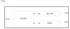
17 is a diagram showing the configuration of a base station according to the present disclosure.
이하, 본 개시의 실시예를 첨부된 도면을 참조하여 상세하게 설명한다.Hereinafter, embodiments of the present disclosure will be described in detail with reference to the accompanying drawings.
실시예를 설명함에 있어서 본 발명이 속하는 기술 분야에 익히 알려져 있고 본 발명과 직접적으로 관련이 없는 기술 내용에 대해서는 설명을 생략한다. 이는 불필요한 설명을 생략함으로써 본 발명의 요지를 흐리지 않고 더욱 명확히 전달하기 위함이다.In describing the embodiments, descriptions of technical contents that are well known in the technical field to which the present invention pertains and are not directly related to the present invention will be omitted. This is to more clearly convey the gist of the present invention without obscuring it by omitting unnecessary description.
마찬가지 이유로 첨부된 도면에 있어서 일부 구성요소는 과장되거나 생략되거나 개략적으로 도시되었다. 또한, 각 구성요소의 크기는 실제 크기를 전적으로 반영하는 것이 아니다. 각 도면에서 동일한 또는 대응하는 구성 요소에는 동일한 참조 번호를 부여하였다.For the same reason, in the accompanying drawings, some components are exaggerated, omitted, or schematically illustrated. Also, the size of each component does not entirely reflect the actual size. In each figure, the same reference number is given to the same or corresponding component.
본 개시의 이점 및 특징, 그리고 그것들을 달성하는 방법은 첨부되는 도면과 함께 상세하게 후술되어 있는 실시예들을 참조하면 명확해질 것이다. 그러나 본 개시는 이하에서 설명되는 실시예들에 한정되는 것이 아니라 서로 다른 다양한 형태로 구현될 수 있으며, 단지 본 실시예들은 본 발명의 개시가 완전하도록 하고, 본 개시가 속하는 기술분야에서 통상의 지식을 가진 자에게 기술적 사상의 범주를 완전하게 알려주기 위해 제공되는 것이며, 본 개시는 청구항의 범주에 의해 정의될 뿐이다. 명세서 전체에 걸쳐 동일 참조 부호는 동일 구성 요소를 지칭한다. 또한, 본 개시를 설명함에 있어서 관련된 기능 또는 구성에 대한 구체적인 설명이 본 개시의 요지를 불필요하게 흐릴 수 있다고 판단된 경우 그 상세한 설명은 생략한다. 그리고 후술되는 용어들은 본 개시에서의 기능을 고려하여 정의된 용어들로서 이는 사용자, 운용자의 의도 또는 관례 등에 따라 달라질 수 있다. 그러므로 그 정의는 본 명세서 전반에 걸친 내용을 토대로 내려져야 할 것이다.Advantages and features of the present disclosure, and methods of achieving them, will become clear with reference to the embodiments described below in detail in conjunction with the accompanying drawings. However, the present disclosure is not limited to the embodiments described below and may be implemented in various different forms, only the present embodiments make the disclosure of the present invention complete, and common knowledge in the art to which the present disclosure belongs. It is provided to completely inform those who have the scope of the technical idea, and the present disclosure is only defined by the scope of the claims. Like reference numbers designate like elements throughout the specification. In addition, in describing the present disclosure, if it is determined that a detailed description of a related function or configuration may unnecessarily obscure the gist of the present disclosure, the detailed description will be omitted. In addition, terms to be described later are terms defined in consideration of functions in the present disclosure, which may vary according to intentions or customs of users or operators. Therefore, the definition should be made based on the contents throughout this specification.
이하, 기지국은 단말의 자원할당을 수행하는 주체로서, gNode B, eNode B, Node B, BS (Base Station), 무선 접속 유닛, 기지국 제어기, 또는 네트워크 상의 노드 중 적어도 하나일 수 있다. 단말은 UE (User Equipment), MS (Mobile Station), 셀룰러폰, 스마트폰, 컴퓨터, 또는 통신기능을 수행할 수 있는 멀티미디어시스템을 포함할 수 있다. 본 개시에서 하향링크(Downlink; DL)는 기지국이 단말에게 전송하는 신호의 무선 전송경로이고, 상향링크는(Uplink; UL)는 단말이 기국에게 전송하는 신호의 무선 전송경로를 의미한다. 또한, 이하에서 LTE 또는 LTE-A 시스템을 일예로서 설명할 수도 있지만, 유사한 기술적 배경 또는 채널형태를 갖는 여타의 통신시스템에도 본 개시의 실시예가 적용될 수 있다. 예를 들어 LTE-A 이후에 개발되는 5세대 이동통신 기술(5G, new radio, NR)이 이에 포함될 수 있으며, 이하의 5G는 기존의 LTE, LTE-A 및 유사한 다른 서비스를 포함하는 개념일 수도 있다. 또한, 본 개시는 숙련된 기술적 지식을 가진 자의 판단으로써 본 개시의 범위를 크게 벗어나지 아니하는 범위에서 일부 변형을 통해 다른 통신시스템에도 적용될 수 있다.Hereinafter, a base station is a subject that performs resource allocation of a terminal, and may be at least one of a gNode B, an eNode B, a Node B, a base station (BS), a wireless access unit, a base station controller, or a node on a network. The terminal may include a user equipment (UE), a mobile station (MS), a cellular phone, a smart phone, a computer, or a multimedia system capable of performing communication functions. In the present disclosure, downlink (DL) is a radio transmission path of a signal transmitted from a base station to a terminal, and uplink (UL) refers to a radio transmission path of a signal transmitted from a terminal to a base station. In addition, although an LTE or LTE-A system may be described below as an example, embodiments of the present disclosure may be applied to other communication systems having a similar technical background or channel type. For example, the 5th generation mobile communication technology (5G, new radio, NR) developed after LTE-A may be included in this, and the following 5G may be a concept including existing LTE, LTE-A and other similar services there is. In addition, the present disclosure can be applied to other communication systems through some modifications within a range that does not greatly deviate from the scope of the present disclosure as determined by those skilled in the art.
이때, 처리 흐름도 도면들의 각 블록과 흐름도 도면들의 조합들은 컴퓨터 프로그램 인스트럭션들에 의해 수행될 수 있음을 이해할 수 있을 것이다. 이들 컴퓨터 프로그램 인스트럭션들은 범용 컴퓨터, 특수용 컴퓨터 또는 기타 프로그램 가능한 데이터 프로세싱 장비의 프로세서에 탑재될 수 있으므로, 컴퓨터 또는 기타 프로그램 가능한 데이터 프로세싱 장비의 프로세서를 통해 수행되는 그 인스트럭션들이 흐름도 블록(들)에서 설명된 기능들을 수행하는 수단을 생성하게 된다. 이들 컴퓨터 프로그램 인스트럭션들은 특정 방식으로 기능을 구현하기 위해 컴퓨터 또는 기타 프로그램 가능한 데이터 프로세싱 장비를 지향할 수 있는 컴퓨터 이용 가능 또는 컴퓨터 판독 가능 메모리에 저장되는 것도 가능하므로, 그 컴퓨터 이용가능 또는 컴퓨터 판독 가능 메모리에 저장된 인스트럭션들은 흐름도 블록(들)에서 설명된 기능을 수행하는 인스트럭션 수단을 내포하는 제조 품목을 생산하는 것도 가능하다. 컴퓨터 프로그램 인스트럭션들은 컴퓨터 또는 기타 프로그램 가능한 데이터 프로세싱 장비 상에 탑재되는 것도 가능하므로, 컴퓨터 또는 기타 프로그램 가능한 데이터 프로세싱 장비 상에서 일련의 동작 단계들이 수행되어 컴퓨터로 실행되는 프로세스를 생성해서 컴퓨터 또는 기타 프로그램 가능한 데이터 프로세싱 장비를 수행하는 인스트럭션들은 흐름도 블록(들)에서 설명된 기능들을 실행하기 위한 단계들을 제공하는 것도 가능하다.At this time, it will be understood that each block of the process flow chart diagrams and combinations of the flow chart diagrams can be performed by computer program instructions. These computer program instructions may be embodied in a processor of a general purpose computer, special purpose computer, or other programmable data processing equipment, so that the instructions executed by the processor of the computer or other programmable data processing equipment are described in the flowchart block(s). It creates means to perform functions. These computer program instructions may also be stored in a computer usable or computer readable memory that can be directed to a computer or other programmable data processing equipment to implement functionality in a particular way, such that the computer usable or computer readable memory The instructions stored in are also capable of producing an article of manufacture containing instruction means that perform the functions described in the flowchart block(s). The computer program instructions can also be loaded on a computer or other programmable data processing equipment, so that a series of operational steps are performed on the computer or other programmable data processing equipment to create a computer-executed process to generate computer or other programmable data processing equipment. Instructions for performing processing equipment may also provide steps for performing the functions described in the flowchart block(s).
또한, 각 블록은 특정된 논리적 기능(들)을 실행하기 위한 하나 이상의 실행 가능한 인스트럭션들을 포함하는 모듈, 세그먼트 또는 코드의 일부를 나타낼 수 있다. 또, 몇 가지 대체 실행 예들에서는 블록들에서 언급된 기능들이 순서를 벗어나서 발생하는 것도 가능함을 주목해야 한다. 예를 들면, 잇달아 도시되어 있는 두 개의 블록들은 사실 실질적으로 동시에 수행되는 것도 가능하고 또는 그 블록들이 때때로 해당하는 기능에 따라 역순으로 수행되는 것도 가능하다.Additionally, each block may represent a module, segment, or portion of code that includes one or more executable instructions for executing specified logical function(s). It should also be noted that in some alternative implementations it is possible for the functions mentioned in the blocks to occur out of order. For example, it is possible that two blocks shown in succession may in fact be performed substantially concurrently, or that the blocks may sometimes be performed in reverse order depending on their function.
이때, 본 실시예에서 사용되는 '~부'라는 용어는 소프트웨어 또는 FPGA(Field Programmable Gate Array) 또는 ASIC(Application Specific Integrated Circuit)과 같은 하드웨어 구성요소를 의미하며, '~부'는 어떤 역할들을 수행한다. 그렇지만 '~부'는 소프트웨어 또는 하드웨어에 한정되는 의미는 아니다. '~부'는 어드레싱할 수 있는 저장 매체에 있도록 구성될 수도 있고 하나 또는 그 이상의 프로세서들을 재생시키도록 구성될 수도 있다. 따라서, 일 예로서 '~부'는 소프트웨어 구성요소들, 객체지향 소프트웨어 구성요소들, 클래스 구성요소들 및 태스크 구성요소들과 같은 구성요소들과, 프로세스들, 함수들, 속성들, 프로시저들, 서브루틴들, 프로그램 코드의 세그먼트들, 드라이버들, 펌웨어, 마이크로코드, 회로, 데이터, 데이터베이스, 데이터 구조들, 테이블들, 어레이들, 및 변수들을 포함한다. 구성요소들과 '~부'들 안에서 제공되는 기능은 더 작은 수의 구성요소들 및 '~부'들로 결합되거나 추가적인 구성요소들과 '~부'들로 더 분리될 수 있다. 뿐만 아니라, 구성요소들 및 '~부'들은 디바이스 또는 보안 멀티미디어카드 내의 하나 또는 그 이상의 CPU들을 재생시키도록 구현될 수도 있다. 또한 실시예에서 ‘~부’는 하나 이상의 프로세서를 포함할 수 있다.At this time, the term '~unit' used in this embodiment means software or hardware components such as FPGA (Field Programmable Gate Array) or ASIC (Application Specific Integrated Circuit), and '~unit' performs certain roles. do. However, '~ part' is not limited to software or hardware. '~bu' may be configured to be in an addressable storage medium and may be configured to reproduce one or more processors. Therefore, as an example, '~unit' refers to components such as software components, object-oriented software components, class components, and task components, processes, functions, properties, and procedures. , subroutines, segments of program code, drivers, firmware, microcode, circuitry, data, databases, data structures, tables, arrays, and variables. Functions provided within components and '~units' may be combined into smaller numbers of components and '~units' or further separated into additional components and '~units'. In addition, components and '~units' may be implemented to play one or more CPUs in a device or a secure multimedia card. Also, in the embodiment, '~ unit' may include one or more processors.
무선 통신 시스템은 초기의 음성 위주의 서비스를 제공하던 것에서 벗어나 예를 들어, 3GPP의 HSPA(High Speed Packet Access), LTE(Long Term Evolution 또는 E-UTRA (Evolved Universal Terrestrial Radio Access)), LTE-Advanced (LTE-A), LTE-Pro, 3GPP2의 HRPD(High Rate Packet Data), UMB(Ultra Mobile Broadband), 및 IEEE의 802.16e 등의 통신 표준과 같이 고속, 고품질의 패킷 데이터 서비스를 제공하는 광대역 무선 통신 시스템으로 발전하고 있다.The wireless communication system has moved away from providing voice-oriented services in the early days and, for example, 3GPP's HSPA (High Speed Packet Access), LTE (Long Term Evolution or E-UTRA (Evolved Universal Terrestrial Radio Access)), LTE-Advanced (LTE-A), LTE-Pro, 3GPP2's High Rate Packet Data (HRPD), UMB (Ultra Mobile Broadband), and IEEE's 802.16e, a broadband wireless network that provides high-speed, high-quality packet data services. evolving into a communication system.
광대역 무선 통신 시스템의 대표적인 예로, LTE 시스템에서는 하향링크(Downlink; DL)에서는 OFDM(Orthogonal Frequency Division Multiplexing) 방식을 채용하고 있고, 상향링크(Uplink; UL)에서는 SC-FDMA(Single Carrier Frequency Division Multiple Access) 방식을 채용하고 있다. 상향링크는 단말(UE(User Equipment) 또는 MS(Mobile Station))이 기지국(eNode B, 또는 base station(BS))으로 데이터 또는 제어신호를 전송하는 무선링크를 뜻하고, 하향링크는 기지국이 단말로 데이터 또는 제어신호를 전송하는 무선링크를 뜻한다. 또한, 전술한 다중 접속 방식은, 통상 각 사용자 별로 데이터 또는 제어정보를 실어 보낼 시간-주파수 자원을 서로 겹치지 않도록, 즉 직교성 (Orthogonality)이 성립하도록, 할당 및 운용함으로써 각 사용자의 데이터 또는 제어정보를 구분한다.As a representative example of a broadband wireless communication system, in an LTE system, an Orthogonal Frequency Division Multiplexing (OFDM) method is adopted in downlink (DL), and SC-FDMA (Single Carrier Frequency Division Multiplexing Access) in uplink (UL) ) method is used. Uplink refers to a radio link in which a terminal (UE (User Equipment) or MS (Mobile Station)) transmits data or control signals to a base station (eNode B or base station (BS)), and downlink refers to a radio link in which a base station transmits data or a control signal to a terminal. A radio link that transmits data or control signals. In addition, the above-described multiple access method is usually used to transmit data or control information for each user by allocating and operating time-frequency resources not to overlap each other, that is, to establish orthogonality. distinguish
LTE 이후의 통신 시스템인 5G 통신시스템은 사용자 및 서비스 제공자 등의 다양한 요구 사항을 자유롭게 반영할 수 있어야 하기 때문에 다양한 요구사항을 동시에 만족하는 서비스가 지원되어야 한다. 5G 통신시스템을 위해 고려되는 서비스로는 향상된 모바일 광대역 통신(enhanced Mobile Broadband, eMBB), 대규모 기계형 통신(massive machine type communication, mMTC), 초신뢰 저지연 통신(Ultra Reliability Low Latency Communciation, URLLC) 등이 있다.Since the 5G communication system, which is a communication system after LTE, must be able to freely reflect various requirements of users and service providers, services that satisfy various requirements at the same time must be supported. Services considered for the 5G communication system include enhanced mobile broadband (eMBB), massive machine type communication (mMTC), ultra reliability low latency communication (URLLC), etc. there is
eMBB는 기존의 LTE, LTE-A 또는 LTE-Pro가 지원하는 데이터 전송 속도보다 더욱 향상된 데이터 전송 속도를 제공하는 것을 목표로 한다. 예를 들어, 5G 통신시스템에서 eMBB는 하나의 기지국 관점에서 하향링크에서는 20Gbps의 최대 전송 속도(peak data rate), 상향링크에서는 10Gbps의 최대 전송 속도를 제공할 수 있어야 한다. 또한 5G 통신시스템은 최대 전송 속도를 제공하는 동시에, 증가된 단말의 실제 체감 전송 속도(User perceived data rate)를 제공해야 한다. 이와 같은 요구 사항을 만족시키기 위해, 더욱 향상된 다중 안테나 (Multi Input Multi Output, MIMO) 전송 기술을 포함하여 다양한 송수신 기술의 향상이 요구될 수 있다. 또한 LTE에서는 2GHz 대역에서 최대 20MHz 전송대역폭을 사용하여 신호가 전송되는 반면에 5G 통신시스템에서는 3~6GHz 또는 6GHz 이상의 주파수 대역에서 20MHz 보다 넓은 주파수 대역폭을 사용함으로써 5G 통신시스템에서 요구하는 데이터 전송 속도를 만족시킬 수 있다.eMBB aims to provide a data transmission rate that is more improved than that supported by existing LTE, LTE-A or LTE-Pro. For example, in a 5G communication system, an eMBB must be able to provide a peak data rate of 20 Gbps in downlink and a peak data rate of 10 Gbps in uplink from the perspective of one base station. In addition, the 5G communication system should provide a maximum transmission rate and, at the same time, an increased user perceived data rate of the terminal. In order to satisfy these requirements, various transmission/reception technologies may be required to be improved, including a more advanced multi-input multi-output (MIMO) transmission technology. In LTE, signals are transmitted using a transmission bandwidth of up to 20 MHz in the 2 GHz band, whereas in the 5G communication system, a frequency bandwidth wider than 20 MHz is used in the 3 to 6 GHz or 6 GHz frequency band, thereby increasing the data transmission rate required by the 5G communication system. can satisfy
동시에, 5G 통신시스템에서 사물 인터넷(Internet of Thing, IoT)과 같은 응용 서비스를 지원하기 위해 mMTC가 고려되고 있다. mMTC에서는 효율적으로 사물 인터넷을 제공하기 위해 셀 내에서 대규모 단말의 접속 지원, 단말의 커버리지 향상, 향상된 배터리 시간, 단말의 비용 감소 등이 요구된다. 사물 인터넷은 여러 가지 센서 및 다양한 기기에 부착되어 통신 기능을 제공하므로 셀 내에서 많은 수의 단말(예를 들어, 1,000,000 단말/km2)을 지원할 수 있어야 한다. 또한 mMTC를 지원하는 단말은 서비스의 특성상 건물의 지하와 같이 셀이 커버하지 못하는 음영지역에 위치할 가능성이 높으므로 5G 통신시스템에서 제공하는 다른 서비스 대비 더욱 넓은 커버리지를 요구한다. mMTC를 지원하는 단말은 저가의 단말로 구성되어야 하며, 단말의 배터리를 자주 교환하기 힘들기 때문에 10~15년과 같이 매우 긴 배터리 생명시간(battery life time)이 요구된다.At the same time, mMTC is being considered to support application services such as Internet of Things (IoT) in 5G communication systems. In mMTC, in order to efficiently provide IoT, support for large-scale terminal access within a cell, improved terminal coverage, improved battery time, and reduced terminal cost are required. Since the Internet of Things is attached to various sensors and various devices to provide communication functions, it must be able to support a large number of terminals (eg, 1,000,000 terminals/km2) in a cell. In addition, terminals supporting mMTC are likely to be located in shadow areas that are not covered by cells, such as the basement of a building due to the nature of the service, so they require wider coverage than other services provided by the 5G communication system. A terminal supporting mMTC must be configured as a low-cost terminal, and since it is difficult to frequently replace a battery of the terminal, a very long battery life time such as 10 to 15 years is required.
마지막으로, URLLC의 경우, 특정한 목적(mission-critical)으로 사용되는 셀룰라 기반 무선 통신 서비스이다. 예를 들어, 로봇(Robot) 또는 기계 장치(Machinery)에 대한 원격 제어(remote control), 산업 자동화(industrial automation), 무인 비행장치(Unmaned Aerial Vehicle), 원격 건강 제어(Remote health care), 비상 상황 알림(emergency alert) 등에 사용되는 서비스 등을 고려할 수 있다. 따라서 URLLC가 제공하는 통신은 매우 낮은 저지연 및 매우 높은 신뢰도를 제공해야 한다. 예를 들어, URLLC을 지원하는 서비스는 0.5 밀리초보다 작은 무선 접속 지연시간(Air interface latency)을 만족해야 하며, 동시에 10-5 이하의 패킷 오류율(Packet Error Rate)의 요구사항을 만족해야 한다. 따라서, URLLC을 지원하는 서비스를 위해 5G 시스템은 다른 서비스보다 작은 전송 시간 구간(Transmit Time Interval, TTI)을 제공해야 하며, 동시에 통신 링크의 신뢰성을 확보하기 위해 주파수 대역에서 넓은 리소스를 할당해야 한다.Finally, in the case of URLLC, it is a cellular-based wireless communication service used for a specific purpose (mission-critical). For example, remote control of robots or machinery, industrial automation, unmaned aerial vehicles, remote health care, emergency situations A service used for emergency alert or the like may be considered. Therefore, the communication provided by URLLC must provide very low latency and very high reliability. For example, a service supporting URLLC must satisfy air interface latency of less than 0.5 milliseconds, and at the same time must satisfy requirements of a packet error rate of 10-5 or less. Therefore, for services supporting URLLC, the 5G system must provide a smaller transmit time interval (TTI) than other services, and at the same time allocate wide resources in the frequency band to secure the reliability of the communication link.
5G의 세가지 서비스들, 즉 eMBB, URLLC, mMTC는 하나의 시스템에서 다중화되어 전송될 수 있다. 이 때, 각각의 서비스들이 갖는 상이한 요구사항을 만족시키기 위해 서비스간에 서로 다른 송수신 기법 및 송수신 파라메터를 사용할 수 있다.The three services of 5G, namely eMBB, URLLC, and mMTC, can be multiplexed and transmitted in one system. At this time, different transmission/reception techniques and transmission/reception parameters may be used between services in order to satisfy different requirements of each service.
이하 본 개시의 다양한 실시 예를 첨부한 도면과 함께 상세히 설명한다. 이하에서는 5G 무선 통신 시스템을 일례로서 본 개시의 다양한 실시 예를 설명하지만, 유사한 기술적 배경 또는 채널형태를 갖는 여타의 통신시스템에도 본 개시의 다양한 실시예가 적용될 수 있다. 5G 통신 시스템뿐만 아니라 LTE 및 LTE-A 또는 5G 이후의 통신 시스템에도 본 개시의 다양한 실시예가 적용될 수 있다. 또한, 본 개시의 다양한 실시 예는 숙련된 기술적 지식을 가진자의 판단으로써 본 개시의 범위를 크게 벗어나지 아니하는 범위에서 일부 변형을 통해 다른 통신시스템에도 적용될 수 있다.Hereinafter, various embodiments of the present disclosure will be described in detail with accompanying drawings. Hereinafter, various embodiments of the present disclosure are described using a 5G wireless communication system as an example, but various embodiments of the present disclosure may be applied to other communication systems having a similar technical background or channel type. Various embodiments of the present disclosure may be applied not only to 5G communication systems but also to communication systems after LTE and LTE-A or 5G. In addition, various embodiments of the present disclosure can be applied to other communication systems through some modification within a range that does not greatly deviate from the scope of the present disclosure based on the judgment of a person having skilled technical knowledge.
본 개시를 설명함에 있어서 관련된 기능 또는 구성에 대한 구체적인 설명이 본 개시의 요지를 불필요하게 흐릴 수 있다고 판단된 경우 그 상세한 설명은 생략한다. 그리고 후술되는 용어들은 본 발명에서의 기능을 고려하여 정의된 용어들로서 이는 사용자, 운용자의 의도 또는 관례 등에 따라 달라질 수 있다. 그러므로 그 정의는 본 명세서 전반에 걸친 내용을 토대로 내려져야 할 것이다.In describing the present disclosure, if it is determined that a detailed description of a related function or configuration may unnecessarily obscure the subject matter of the present disclosure, the detailed description will be omitted. In addition, terms to be described later are terms defined in consideration of functions in the present invention, which may vary according to the intention or custom of a user or operator. Therefore, the definition should be made based on the contents throughout this specification.
이하 5G 시스템의 프레임 구조에 대해 도면을 참조하여 보다 구체적으로 설명한다.Hereinafter, the frame structure of the 5G system will be described in more detail with reference to the drawings.
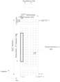
도 1은 본 개시에 따른 5G 시스템에서 데이터 또는 제어채널이 전송되는 무선 자원 영역인 시간-주파수 영역의 기본 구조를 도시한 도면이다.1 is a diagram showing the basic structure of a time-frequency domain, which is a radio resource domain in which data or control channels are transmitted in a 5G system according to the present disclosure.
도 1에서, 가로축은 시간 영역을 나타내고, 세로축은 주파수 영역을 나타낸다. 시간 및 주파수 영역에서 자원의 기본 단위는 자원 요소(Resource Element, RE, 101)로서 시간 축으로 1개의 OFDM(Orthogonal Frequency Division Multiplexing) 심볼(102) 및 주파수 축으로 1개의 부반송파(Subcarrier)(103)로 정의될 수 있다. 주파수 영역에서

도 2는 본 개시에 따른 5G 시스템에서 고려하는 슬롯 구조를 도시한 도면이다.2 is a diagram illustrating a slot structure considered in a 5G system according to the present disclosure.
도 2에는 프레임(Frame, 200), 서브프레임(Subframe, 201), 슬롯(Slot, 202) 구조의 일 예가 도시되어 있다. 1개의 프레임(200)은 10ms로 정의될 수 있다. 1개의 서브프레임(201)은 1ms로 정의될 수 있으며, 따라서 1개의 프레임(200)은 총 10개의 서브프레임(201)으로 구성될 수 있다. 또한, 1개의 슬롯(202, 203)은 14개의 OFDM 심볼로 정의될 수 있다 (즉, 1개의 슬롯 당 심볼 수 (


[표 1][Table 1]

다음으로 5G에서 상향링크 데이터채널(physical uplink shared channel, PUSCH)를 전송하는 방법에 대해 구체적으로 설명하도록 한다.Next, a method of transmitting a physical uplink shared channel (PUSCH) in 5G will be described in detail.
단말이 기지국으로 PUSCH를 전송하는 방법은 크게 승인(Grant)-기반 전송 방식과 비승인(Grant free 또는 Configured grant 또는 Configured scheduling으로 명명될 수 있음)-기반 전송 방식으로 구분될 수 있다.A method of transmitting a PUSCH from a UE to a base station may be largely divided into a grant-based transmission method and a non-grant (which may be named as Grant free, Configured grant, or Configured scheduling)-based transmission method.
승인-기반 PUSCH 전송 방식에서는 단말이, 기지국으로 전송하고자 하는 트래픽(Traffic)이 발생하였을 경우, 기지국으로 스케쥴링 요청(Scheduling Request) 메시지를 상향링크 제어채널(Physical Uplink Control Channel, PUCCH)로 전송할 수 있다. 이 때, 스케쥴링 요청 메시지를 수신한 기지국은 해당 단말에게 스케쥴링 승인에 해당하는 상향링크 스케쥴링을 위한 DCI를 전송할 수 있다. 단말은 PDCCH에 대한 모니터링을 통해 상향링크 스케쥴링을 위한 DCI를 수신할 수 있고, DCI로 통지된 제어 정보에 기반하여 기지국으로 PUSCH를 전송할 수 있다.In the grant-based PUSCH transmission method, when traffic to be transmitted to the base station occurs, the terminal transmits a scheduling request message to the base station through a physical uplink control channel (PUCCH). . At this time, the base station receiving the scheduling request message may transmit DCI for uplink scheduling corresponding to scheduling grant to the corresponding terminal. The terminal may receive DCI for uplink scheduling through monitoring of the PDCCH, and may transmit the PUSCH to the base station based on control information notified through the DCI.
비승인-기반 PUSCH 전송 방식에서는 먼저 기지국이 단말에게 준정적(Semi-static)인 시간/주파수 자원을 상위 계층 시그널링(higher layer signaling), 예컨대 RRC(Radio Resource Control) 시그널링)으로 설정할 수 있다. 단말은 기지국으로 전송하고자 하는 트래픽(Traffic)이 발생하였을 경우, 설정된 시간/주파수 자원에서 기지국 승인 없이 바로 PUSCH를 전송할 수 있다. 비승인-기반 전송 방식에 대해서는 보다 구체적으로 후술하도록 한다.In the non-acknowledgment-based PUSCH transmission scheme, the base station may first set semi-static time/frequency resources to the terminal through higher layer signaling, for example, radio resource control (RRC) signaling. When traffic to be transmitted to the base station occurs, the terminal may directly transmit the PUSCH without approval of the base station in a set time/frequency resource. The non-acknowledgment-based transmission method will be described later in more detail.
다음으로 5G에서 상향링크 데이터채널(Physical Uplink Shared Channel; PUSCH) 전송을 위한 송신 구조를 설명하도록 한다.Next, a transmission structure for transmission of a physical uplink shared channel (PUSCH) in 5G will be described.
도 3은 본 개시에 따른 5G에서의 상향링크 데이터채널 전송을 위한 송신단 구조를 설명하기 위한 도면이다.3 is a diagram for explaining the structure of a transmitter for transmission of an uplink data channel in 5G according to the present disclosure.
도 3에 따르면, PUSCH를 위한 송신단은 FEC(Forward Error Correction)(301), 비트-레벨 스크램블러(Bit Level Scrambler)(302), 변조기(modulator)(303) 및 RE 매퍼(RE mapper)(304)로 구성될 수 있다. FEC(301)는 입력된 비트 시퀀스(bit Sequence, 300)에 대한 채널 코딩을 수행하는 역할을 수행할 수 있다. 또한 FEC(301)는 입력된 비트 시퀀스를 반복(repetition)하는 역할을 수행할 수 있다.According to FIG. 3, the transmitter for the PUSCH includes a Forward Error Correction (FEC) 301, a
비트-레벨 스크램블러(302)는 FEC(301)를 거쳐 출력된 총 Mbit 비트의 비트 시퀀스(


[표 2][Table 2]

비트-레벨 스크램블러(302)를 거친 비트 시퀀스(

[표 3][Table 3]

변조기(303)을 거친 변조 심볼 시퀀스(
하기의 표 4에 따르면, PUSCH의 송신을 위해 사용되는 안테나 포트들 각각에 대해, 송신 파워를 [5, TS 38.213]에 맞추기 위해 콤플렉스-값의 심볼들의 블록인


[표 4][Table 4]

다음으로 5G에서 NOMA에 기반한 PUSCH 전송을 위한 송신 구조를 설명하도록 한다. 도 4은 본 개시에 따른 5G에서 비직교다중접속 모드에서의 송신단 구조를 도시한 도면이다.Next, a transmission structure for PUSCH transmission based on NOMA in 5G will be described. 4 is a diagram illustrating a structure of a transmitter in a non-orthogonal multiple access mode in 5G according to the present disclosure.
도 4에 따르면, NOMA를 위해 송신단에서 수행되는 동작은 비트-레벨 동작(bit-level operation)(401)과 심볼-레벨 동작(symbol-level operation)(402)으로 구성될 수 있다.According to FIG. 4, an operation performed by a transmitter for NOMA may include a bit-
비트-레벨 동작(401)을 수행하는 장치는 FEC(403)와 비트-레벨 인터리버/스크램블러(bit-level interleaver/scrambler)(404)를 포함할 수 있다. FEC(403)는 입력된 비트 시퀀스(bit Sequence, 400)에 대한 채널 코딩을 수행하는 역할을 수행할 수 있다. 또한 입력된 비트 시퀀스(400)를 반복(repetition)할 수 있다. 비트-레벨 인터리버/스크램블러(404)는 FEC(403)를 거쳐 출력된 비트에 대한 인터리빙 및 스크램블링 동작을 수행할 수 있다. 비트-레벨 인터리버/스크램블러(404) 블록에서 사용될 인터리버/스크램블러는 셀-특정적이거나 단말-특정적일 수 있으며, 이를 통해 같은 시간 및 주파수 자원을 이용해 신호를 전송하는 다른 단말에게 미치는 간섭을 랜덤화할 수 있다.A device performing the bit-
심볼-레벨 동작(402)을 수행하는 장치는 변조된 심볼 시퀀스 생성기(modulated (405)와 심볼-to-RE 매핑(406)을 포함할 수 있다. 변조된 심볼 시퀀스 생성기(405) 및 심볼-to-RE 매핑(406) 블록은 단일 또는 다중 톤(tone) 변조, (반복을 통한) 단말-특정 심볼 스프레딩(Spreading), 셀 또는/및 단말-특정적인 심볼-레벨 인터리버/스크램블러, 희박한(sparse)_또는 희박하지 않은(non-sparse) 자원 매핑, 송신 전력 조절 기능 등을 포함할 수 있다.Devices that perform symbol-
이러한 NOMA를 위한 송신단 구조는 도 4에 도시된 구조에 한정되지 않으며, 이러한 동작은 다른 구조에 의해서도 수행될 수 있다.The transmitter structure for this NOMA is not limited to the structure shown in FIG. 4, and this operation can be performed by other structures as well.
NOMA로 동작하는 단말들은 전술한 도 4의 송신 구조에 따라 전송하고자 하는 상향링크 데이터를 변조하여 PUSCH를 통해 기지국으로 전송할 수 있다. 이 때, NOMA를 수행하는 다수의 단말들은 동일한 시간 및 주파수 자원에서 자신의 PUSCH를 동시에 전송할 수 있다. 따라서 다수의 단말들의 PUSCH는 서로 간섭을 미칠 수 있다. 하지만 각각의 단말들은 기지국으로부터 직접적으로 MA(multiple access) 시그니쳐(Signature) ID를 받거나 간접적으로 단말-특정적인 식별자(단말 ID, DMRS 스크램블링 ID, 기지국이 추가로 설정한 ID 등)를 통해 MA 시그니쳐 ID를 추정 할 수 있다. 따라서 NOMA를 수행하는 다수 단말의 PUSCH를 수신한 기지국은 각각의 단말이 사용한 MA 시그니쳐 ID(비승인 기반 전송에서는 기지국이 MA 시그니쳐 ID를 통해 특정 단말이 전송한 것을 추정할 수 있다.)를 기반으로 전술한 송신 구조를 고려한 수신기를 이용하여 각 단말의 상향링크 데이터를 복구할 수 있다.Terminals operating in NOMA may modulate uplink data to be transmitted according to the transmission structure of FIG. 4 and transmit the modulated uplink data to the base station through the PUSCH. At this time, a plurality of terminals performing NOMA may simultaneously transmit their own PUSCHs in the same time and frequency resources. Therefore, PUSCHs of multiple UEs may interfere with each other. However, each terminal receives a multiple access (MA) signature ID directly from the base station or indirectly through a terminal-specific identifier (terminal ID, DMRS scrambling ID, ID additionally set by the base station, etc.) can be estimated. Therefore, the base station receiving the PUSCH of multiple terminals performing NOMA is based on the MA signature ID used by each terminal (in unacknowledged transmission, the base station can estimate that a specific terminal has transmitted through the MA signature ID). Uplink data of each terminal can be recovered using a receiver considering the above-described transmission structure.
다음으로 5G에서 고려 중인 상향링크 비직교다중접속(NOMA)을 위한 수신단 구조에 대해 구체적으로 설명하도록 한다. 비직교다중접속이란 동일한 시간 및 주파수 자원에서 다수의 단말에게 통신 서비스를 제공하는 기술을 의미한다. 예컨대 동일한 시간 및 주파수 자원에서 다수의 단말이 상향링크 데이터 채널을 전송할 수 있다.Next, a structure of a receiving end for uplink non-orthogonal multiple access (NOMA) being considered in 5G will be described in detail. Non-orthogonal multiple access means a technology that provides communication services to multiple terminals in the same time and frequency resources. For example, multiple terminals may transmit uplink data channels in the same time and frequency resources.
도 5은 본 개시에 따른 5G에서 논의하고 있는 NOMA를 위한 수신단 구조를 설명하기 위한 도면이다.5 is a diagram for explaining a structure of a receiving end for NOMA discussed in 5G according to the present disclosure.
도 5에 따르면, NOMA를 위한 수신단은 검출기 (Detector, 501), 복호기 (Decoder, 502), 간섭제거기 (Interference Cancellation, 503)의 블록으로 구성될 수 있다.According to FIG. 5, a receiving end for NOMA may be composed of blocks of a detector (501), a decoder (502), and an interference cancellation (503).
수신기로 수신된 신호(500)는 검출기(501)를 거쳐 채널에 의한 신호 왜곡이 보상될 수 있다. 검출기(501)를 거친 출력 신호는 복호기(502)로 입력되어 채널 코딩에 대한 복호 과정을 거칠 수 있다. 복호기(502)를 거친 출력 신호는 간섭제거기(503)를 거쳐 추가적인 간섭 제거 동작이 수행될 수 있다. 여기서 간섭 제거 동작이란 예컨대 NOMA에서 사용자간 신호 간섭을 제거하기 위한 목적의 다양한 신호처리 기법이 포함될 수 있다. 간섭제거기(503)를 거친 출력 값은 다시 복호기(501)로 입력될 수 있고, 전술한 절차가 반복 수행될 수 있다. 전술한 절차의 반복 수행 후 NOMA 수신기는 최종 출력 값으로 비트 시퀀스(504)를 출력할 수 있다.The
다음으로 5G의 비승인-기반 전송 방식에 대해 설명하도록 한다.Next, the non-grant-based transmission method of 5G will be described.
도 6은 본 개시에 따른 5G의 비승인-기반 전송 방식의 일 예를 설명하기 위한 도면이다.6 is a diagram for explaining an example of a 5G non-grant-based transmission scheme according to the present disclosure.
5G에서는 상향링크 데이터 채널(Physical Uplink Shared Channel; PUSCH)에 대한 비승인(Configured Grant, Grant free, 등으로 명명됨)-기반 전송 방법에 대하여 두 가지 타입(비승인-기반 PUSCH 전송 타입-1 (Type-1 PUSCH transmission with a configured grant), 비승인-기반 PUSCH 전송 타입-2 (Type-1 PUSCH transmission with a configured grant)을 지원한다.In 5G, two types (unacknowledged-based PUSCH transmission type-1 (named as Configured Grant, Grant free, etc.)-based transmission method for an uplink data channel (Physical Uplink Shared Channel; PUSCH) Supports Type-1 PUSCH transmission with a configured grant) and unacknowledgment-based PUSCH transmission Type-2 (Type-1 PUSCH transmission with a configured grant).
[비승인-기반 PUSCH 전송 타입-1][Unacknowledged-based PUSCH transmission type-1]
비승인-기반 PUSCH 전송 타입-1에서는 기지국이 단말에게 비승인-기반 PUSCH 전송을 허용하는 특정 시간/주파수 자원(600)을 상위 계층 시그널링, 예컨대 RRC 시그널링을 통해 설정해줄 수 있다. 예컨대 도 6에 도시된 바와 같이 자원(600)에 대한 시간축 할당 정보(601), 주파수축 할당 정보(602), 주기 정보(603) 등이 RRC 시그널링을 통해 설정될 수 있다. 또한 기지국은 단말에게 PUSCH 전송을 위한 다양한 파라미터들(예컨대, 주파수 호핑, DMRS 설정, MCS(modulation and coding scheme) 테이블, MCS, RBG(Resource Block Group) 크기, 반복 전송 횟수, RV(Redundancy Version) 등)을 상위 계층 시그널링을 통해 설정해 줄 수 있다. 보다 구체적으로는 하기 표 5의 설정 정보들이 포함될 수 있다.In the non-grant-based PUSCH transmission type-1, the base station may set a specific time/
[표 5][Table 5]


기지국으로부터 비승인-기반 PUSCH 전송 타입-1을 위한 설정정보를 수신하였을 경우, 단말은 주기적으로 설정된 자원(600)으로 기지국의 승인 없이 PUSCH를 전송할 수 있다. PUSCH를 전송하기 위해 필요한 다양한 파라미터들 (예컨대, 주파수 호핑, DMRS 설정, MCS, RBG(Resource Block Group) 크기, 반복 전송 횟수, RV(Redundancy Version), 프리코딩과 레이어 수, 안테나 포트, 주파수 호핑 오프셋 등)은 모두 기지국의 통지한 설정 값을 따를 수 있다.When receiving configuration information for non-acknowledgment-based PUSCH transmission type-1 from the base station, the terminal may transmit the PUSCH through the periodically configured
[비승인-기반 PUSCH 전송 타입-2][Unacknowledged-based PUSCH Transmission Type-2]
비승인-기반 PUSCH 전송 타입-2에서는 기지국이 단말에게 비승인-기반 PUSCH 전송을 허용하는 특정 시간/주파수 자원(600)에 대한 정보 중 일부(예컨대 주기 정보(603) 등)를 상위 계층 시그널링 (예컨대 RRC 시그널링)으로 설정할 수 있다. 또한 기지국은 단말에게 PUSCH 전송을 위한 다양한 파라미터들 (예컨대, 주파수 호핑, DMRS 설정, MCS 테이블, RBG(Resource Block Group) 크기, 반복 전송 횟수, RV(Redundancy Version) 등)을 상위 계층 시그널링으로 설정해 줄 수 있다. 보다 구체적으로는 기지국은 단말에게 하기 표 6의 설정 정보들을 상위 계층 시그널링으로 설정해 줄 수 있다.In unlicensed-based PUSCH transmission type-2, the base station transmits some of the information (eg, period information 603) on a specific time/
[표 6][Table 6]

기지국은 단말에게 CS-RNTI(Configured Scheduling-RNTI)를 설정할 수 있고, 단말은 CS-RNTI로 스크램블링된 DCI 포맷을 모니터링할 수 있다. CS-RNTI로 스크램블링된 DCI는 비승인-기반 PUSCH 전송 타입-2를 활성화하는 목적 (즉, 단말에게 비승인-기반 PUSCH를 허용하는 목적)으로 사용될 수 있다. 예컨대 단말이 수신한 CS-RNTI로 스크램블링 되어 있는 DCI 포맷의 DCI 필드가 하기의 표 7에 기재된 값을 만족할 경우, 이는 비승인-기반 PUSCH 전송에 대한 트리거(Trigger)로 판단될 수 있다.The base station may configure CS-RNTI (Configured Scheduling-RNTI) for the UE, and the UE may monitor the DCI format scrambled with the CS-RNTI. The DCI scrambled with the CS-RNTI may be used for the purpose of activating the unacknowledged-based PUSCH transmission type-2 (ie, the purpose of allowing the unacknowledged-based PUSCH to the UE). For example, if the DCI field of the DCI format scrambled with the CS-RNTI received by the UE satisfies the values listed in Table 7 below, this may be determined as a trigger for non-grant-based PUSCH transmission.
[표 7][Table 7]

기지국은 단말에게 상기 특정 필드들의 값을 이용하여 비승인-기반 PUSCH 전송에 대한 트리거를 지시함과 동시에 비승인-기반 PUSCH 전송을 수행할 수 있는 자원 영역(600)에 대한 구체적인 시간 할당 정보(601) 및 주파수 할당 정보(602)를 해당 DCI의 자원 할당 필드로 단말에게 통지할 수 있다. 단말은 상위 계층으로 설정된 주기 정보(603)와 트리거에 해당하는 CS-RNTI로 스크램블링된 DCI로부터 획득한 시간 자원할당 정보(601) 및 주파수 자원할당 정보(602)로부터 비승인-기반 PUSCH 전송을 위한 자원 영역(600)을 판단할 수 있고, 해당 자원 영역(600)으로 비승인-기반 PUSCH 전송을 수행할 수 있다. 즉 트리거에 해당하는 DCI를 수신한 시점 이후부터, 단말은 주기적으로 설정된 자원(600)으로 기지국의 승인 없이 PUSCH를 전송할 수 있다. 단말은 PUSCH를 전송하기 위해 필요한 다양한 파라미터들 중에서 일부 (예컨대, DMRS 설정 정보, MCS 테이블, RBG 크기, 반복 전송 횟수, RV, 전력 조절 파라미터 등 상기 표 6의 파라미터들)은 모두 기지국이 상위 계층 시그널링으로 설정한 값을 따를 수 있고, 그 외 파라미터들(예컨대, MCS, 프리코딩과 레이어 수, 안테나 포트, 주파수 호핑 오프셋 등 DCI 포맷 0_0/0_1의 필드에 해당하는 파라미터들)은 수신한 트리거 용 CS-RNTI로 스크램블링된 DCI로부터 통지된 설정 값을 따를 수 있다.The base station instructs the terminal to trigger the unlicensed-based PUSCH transmission using the values of the specific fields, and at the same time, the specific
기지국은 단말에게 비승인-기반 PUSCH 전송을 릴리즈하는 목적(즉, 단말에게 비승인-기반 PUSCH 전송 허용을 중단하는 목적)으로 CS-RNTI로 스크램블링된 DCI를 전송할 수 있고, 이 때 단말이 수신한 CS-RNTI로 스크램블링된 DCI 포맷의 필드가 하기의 표 8의 값을 만족할 경우, 단말은 이를 비승인-기반 PUSCH 전송에 대한 릴리즈(Release)로 판단할 수 있다.The base station may transmit the DCI scrambled with the CS-RNTI for the purpose of releasing the unlicensed-based PUSCH transmission to the UE (ie, the purpose of stopping the UE from allowing the unlicensed-based PUSCH transmission). If the field of the DCI format scrambled with the CS-RNTI satisfies the value of Table 8 below, the terminal may determine this as a release for non-acknowledgment-based PUSCH transmission.
[표 8][Table 8]

다음으로 비승인-기반 전송 방식의 NOMA로 동작하는 단말들이 MA 시그니쳐를 선택하는 방법에 대해 설명하도록 한다.Next, a method for selecting MA signatures by UEs operating in the non-grant-based transmission NOMA will be described.
비승인-기반 PUSCH 전송을 NOMA로 동작하는 단말들이 MA 시그니쳐를 선택하는 방법으로 “Random activation”방법과 “Random Selection”방법이 논의 되고 있다. 상기 두 방법의 이름은 본 개시의 이해를 돕기 위해 명명된 것이며, 다르게 표현 될 수도 있다.“Random activation” method and “Random selection” method are being discussed as a method for UEs operating non-acknowledgment-based PUSCH transmission as NOMA to select MA signatures. The names of the two methods are named to aid understanding of the present disclosure, and may be expressed differently.
“Random activation”방법은 기지국이 동일한 비승인-기반 PUSCH 전송 자원을 사용하는 각각의 단말들에게 비승인-기반 PUSCH 전송 타입에 따라 RRC 신호 또는 DCI를 통해 직접적인 인덱스 또는 간접적(단말-특정 ID, slot index, 비승인-기반 전송 자원 등의 조합으로 표현될 수 있다.)으로 단말-특정 MA 시그니쳐를 할당한다. 기지국과 단말 사이에서 사용 가능한 MA 시그니쳐에 대한 pool Spool = { S1, S2, …, SK }가 정의될 수 있고, 기지국은 단말에게 MA 시그니쳐 인덱스를 RRC 신호 또는 DCI를 통해 지시할 수 있다. 이와 같은 방법의 경우 기지국이 동일한 자원에서 지원하려고 하는 단말의 수와 비교하여 그 이상의 개수의 MA 시그니쳐를 갖고 있다면 여러 단말들이 같은 MA 시그니쳐를 사용하여 전송할 때 발생하는 충돌(NOMA에서 같은 시그니쳐로 여러 단말이 전송하면 기지국이 전송한 단말들을 구분 할 수 없어 수신을 할 수 없게 된다.)이 발생 하지 않을 수 있다.The “Random activation” method is a direct index or indirect (UE-specific ID, slot) through RRC signal or DCI according to the unlicensed-based PUSCH transmission type for each terminal using the same unlicensed-based PUSCH transmission resource. It can be expressed as a combination of index, non-grant-based transmission resource, etc.) and allocates a UE-specific MA signature. Pool Spool for MA signatures available between the base station and the terminal = { S1, S2, ... , SK } may be defined, and the base station may indicate the MA signature index to the terminal through an RRC signal or DCI. In this method, if the base station has a greater number of MA signatures compared to the number of MSs it intends to support in the same resource, collisions that occur when multiple MSs transmit using the same MA signature (multiple MSs with the same signature in NOMA) If this transmission occurs, the base station cannot distinguish the transmitted terminals, so that reception cannot be performed.) may not occur.
“Random selection”방법에 따르면, 기지국의 동일한 비승인-기반 PUSCH 전송 자원을 사용하는 공통의 단말들에게 공통의 MA 시그니쳐 pool(서로 다른 여러 개의 MA 시그니쳐가 포함된다.)이 할당될 수 있다. 그리고 단말들은 무작위 하게 MA 시그니쳐 pool내에 있는 MA 시그니쳐를 선택하고 이를 이용하여 전송을 수행할 수 있다. 이와 같은 방법의 경우 기지국이 한정된 MA 시그니쳐 개수 보다 더 많은 단말을 동일한 자원에서 지원할 수 있다. 특히, 각각의 단말의 전송 주기가 독립적이면서 긴 경우에 유리하다. 하지만 앞서 설명처럼 첫 번째 방법은 단말간의 동일한 MA 시그니쳐 사용을 막을 수 있지만 두 번째 방법은 단말간의 충돌을 막을 수 없다.According to the “Random selection” method, a common MA signature pool (including several different MA signatures) can be allocated to common terminals using the same unlicensed-based PUSCH transmission resource of the base station. In addition, UEs can randomly select an MA signature in the MA signature pool and transmit using it. In this method, the base station can support more terminals than the limited number of MA signatures in the same resource. In particular, it is advantageous when the transmission period of each terminal is independent and long. However, as described above, the first method can prevent the use of the same MA signature between terminals, but the second method cannot prevent collision between terminals.
이 때, MA 시그니쳐를 선택하는 두 가지 방법은 기지국이 단말들에게 상위 계층 시그널링 (RRC 시그널링) 또는 L1 시그널링 (DCI 시그널링)을 통해 설정하거나 각각의 단말들에게 단말-특정 MA 시그니쳐를 설정하는 경우 “Random activation”방법으로 간주될 수 있으며, 각각의 단말들에게 MA 시그니쳐 pool만을 설정해 주는 경우는 “Random selection”방법으로 간주 될 수 있다.At this time, the two methods for selecting the MA signature are when the base station configures the UEs through higher layer signaling (RRC signaling) or L1 signaling (DCI signaling), or when the UE-specific MA signature is configured for each UE. It can be regarded as a “Random activation” method, and the case where only the MA signature pool is set for each terminal can be regarded as a “Random selection” method.
<제 1 실시 예><First Embodiment>
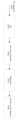
도 7은 본 개시의 일 실시 예에 따라, 기지국이 단말의 연결을 해제하여 단말이 RRC 연결 모드(RRC connected mode)에서 RRC 유휴 모드(RRC idle mode)로 전환하는 절차와, 단말이 기지국과 연결을 설정하여 RRC 유휴 모드(RRC idle mode)에서 RRC 연결 모드(RRC connected mode)로 전환하는 절차를, 설명한 도면이다.7 is a procedure for switching the terminal from an RRC connected mode to an RRC idle mode by disconnecting the terminal by the base station, and connecting the terminal to the base station according to an embodiment of the present disclosure. It is a diagram explaining a procedure for switching from RRC idle mode to RRC connected mode by setting.
기지국은 RRC 연결 모드에서 데이터를 송수신하는 단말이 소정의 이유로 혹은 일정 시간 동안 데이터의 송수신이 없으면 RRC 연결 해제 메시지(RRCRelease 메시지)를 단말에게 보내어 단말을 RRC 유휴모드로 전환하도록 할 수 있다(701). 추후에 현재 연결이 설정되어 있지 않은 단말(이하 idle mode UE)은 전송할 데이터가 발생하면 기지국과 RRC 연결 확립(RRC connection establishment) 과정을 수행할 수 있다. 단말은 랜덤 액세스 과정을 통해서 기지국과 역방향 전송 동기를 수립하고 RRC 연결 요청 메시지(RRCSetupRequest 메시지)를 기지국으로 전송한다(705). RRC 연결 요청 메시지에는 단말의 식별자와 연결을 설정하고자 하는 이유(establishmentCause) 등이 포함될 수 있다. 기지국은 단말이 RRC 연결을 설정하도록 RRC 연결 설정 메시지(RRCSetup 메시지)를 전송한다(710). RRC 연결 설정 메시지에는 RRC 연결 구성 정보 등이 수납될 수 있다. RRC 연결은 SRB (Signaling Radio Bearer)라고도 하며, 단말과 기지국 사이의 제어 메시지인 RRC 메시지 송수신에 사용된다. RRC 연결을 설정한 단말은 RRC 연결 설정 완료 메시지(RRCSetupComplete 메시지)를 기지국으로 전송한다(715). RRC 연결 설정 완료 메시지에는 단말이 소정의 서비스를 위한 베어러 설정을 AMF(access and mobility management function)에게 요청하는 서비스 요청 메시지(Service Request 메시지)가 포함되어 있다. 기지국은 RRC 연결 설정 완료 메시지에 수납된 서비스 요청 메시지가 수납된 초기 단말 메시지를 AMF로 전송하고(720), AMF는 단말이 요청한 서비스를 제공할지 여부를 판단한다. 판단 결과 단말이 요청한 서비스를 제공하기로 결정하였다면 AMF는 기지국에게 초기 단말 컨텍스트 설정 요청 메시지(Initial UE Context Setup Request 메시지)를 전송한다(725). 초기 단말 컨텍스트 설정 요청 메시지에는 DRB (Data Radio Bearer) 설정 시 적용할 QoS (Quality of Service) 정보, 그리고 DRB에 적용할 보안 관련 정보 (예를 들어 Security Key, Security Algorithm) 등이 포함된다. 기지국은 단말과 보안을 설정하기 위해서 보안 모드 명령 메시지(SecurityModeCommand 메시지)(730)와 보안 모드 완료 메시지(SecurityModeComplete 메시지)(735)를 교환한다. 보안 설정이 완료되면 기지국은 단말에게 RRC 연결 재설정 메시지(RRCReconfiguration 메시지)를 전송한다(740). 메시지에는 사용자 데이터가 처리될 DRB의 설정 정보가 포함되며, 단말은 상기 정보를 적용해서 DRB를 설정하고, 기지국에게 RRC 연결 재설정 완료 메시지(RRCReconfigurationComplete 메시지)를 전송한다(745). 단말과 DRB 설정을 완료한 기지국은 AMF에게 초기 단말 컨텍스트 설정 요청 응답 메시지(Initial UE Context Setup Response 메시지)를 전송하고 (750), 이를 수신한 AMF는 UPF(user plane function)와 세션 관리 절차(Session Management Procedure)를 수행하여 PDU 세션을 확립한다(755). 상기 과정이 모두 완료되면 단말은 기지국과 UPF를 통해 데이터를 송수신한다(760, 765). 이처럼 일반적인 데이터 전송 과정은 크게 RRC 연결 설정, 보안 설정, DRB설정의 3단계로 구성된다. 또한 기지국은 소정의 이유로 단말에게 설정을 새로 해주거나 추가하거나 변경하기 위해서 RRCReconfiguration 메시지를 전송할 수 있다(770).The base station may send an RRC connection release message (RRCRelease message) to the terminal to switch the terminal to the RRC idle mode if the terminal transmitting and receiving data in the RRC connection mode does not transmit or receive data for a predetermined reason or for a certain period of time (701) . In the future, when data to be transmitted occurs, a UE (hereinafter referred to as an idle mode UE) for which a connection is not currently established may perform an RRC connection establishment process with the base station. The terminal establishes synchronization with the base station through a random access process and transmits an RRC connection request message (RRCSetupRequest message) to the base station (705). The RRC connection request message may include an identifier of the terminal and a reason for establishing a connection (establishmentCause). The base station transmits an RRC connection setup message (RRCSetup message) to allow the terminal to establish an RRC connection (710). RRC connection configuration information and the like may be stored in the RRC connection establishment message. RRC connection is also referred to as Signaling Radio Bearer (SRB) and is used for transmitting and receiving RRC messages, which are control messages between a terminal and a base station. The terminal that has established the RRC connection transmits an RRC connection setup completion message (RRCSetupComplete message) to the base station (715). The RRC connection establishment completion message includes a service request message (Service Request message) in which the terminal requests an access and mobility management function (AMF) to establish a bearer for a predetermined service. The base station transmits an initial terminal message containing the service request message stored in the RRC connection establishment complete message to the AMF (720), and the AMF determines whether to provide the service requested by the terminal. As a result of the determination, if it is determined to provide the service requested by the terminal, the AMF transmits an initial terminal context setup request message (Initial UE Context Setup Request message) to the base station (725). The initial terminal context setup request message includes Quality of Service (QoS) information to be applied when configuring a Data Radio Bearer (DRB) and security-related information (eg, Security Key, Security Algorithm) to be applied to the DRB. The base station exchanges a security mode command message (SecurityModeCommand message) 730 and a security mode complete message (SecurityModeComplete message) 735 to establish security with the terminal. When the security setting is completed, the base station transmits an RRC connection reconfiguration message (RRCReconfiguration message) to the terminal (740). The message includes configuration information of the DRB in which user data will be processed, and the terminal configures the DRB by applying the information and transmits an RRC connection reconfiguration complete message (RRCReconfigurationComplete message) to the base station (745). The base station that has completed DRB setup with the terminal transmits an initial terminal context setup request response message (Initial UE Context Setup Response message) to the AMF (750), and the AMF that receives it performs a user plane function (UPF) and a session management procedure (Session Management Procedure) to establish a PDU session (755). When all of the above processes are completed, the terminal transmits and receives data with the base station through the UPF (760, 765). As such, the general data transmission process is largely composed of three steps: RRC connection setup, security setup, and DRB setup. In addition, the base station may transmit an RRCReconfiguration message to update, add, or change the configuration to the terminal for a predetermined reason (770).
상기와 같이 단말이 RRC 연결을 설정하여 RRC 유휴 모드에서 RRC 연결 모드로 전환하기 위해서는 많은 시그날링 절차가 요구된다. 따라서 차세대 이동 통신 시스템에서는 RRC 비활성 모드를 정의하였고, 상기와 같은 모드에서는 단말과 기지국이 단말의 컨텍스트를 저장하고 있고, 필요하다면 S1 베어러를 유지하고 있을 수 있기 때문에 상기 RRC 비활성화 모드 단말이 네트워크에 다시 접속하려고 하는 경우, 하기에서 설명하는 RRC 재연결 설정 절차를 통해 더 적은 시그날링 절차로 더 빠르게 접속하고 데이터를 송수신할 수 있다.As described above, many signaling procedures are required for the UE to configure the RRC connection and switch from the RRC idle mode to the RRC connected mode. Therefore, in the next-generation mobile communication system, the RRC inactive mode is defined, and in this mode, the terminal and the base station store the context of the terminal and, if necessary, can maintain the S1 bearer, so that the RRC inactive mode terminal can reconnect to the network. When trying to access, it is possible to access faster and transmit/receive data with fewer signaling procedures through an RRC reconnection setup procedure described below.
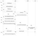
도 8은 본 발명 개시의 일 실시 예에 따라, 기지국이 단말의 연결을 해제하여 단말이 RRC 연결 모드(RRC connected mode)에서 RRC 비활성화 모드(RRC inactive mode)로 전환하는 절차와 단말이 기지국과 연결을 설정하여 RRC 비활성화 모드(RRC inactive mode)에서 RRC 연결 모드(RRC connected mode)로 전환하는 절차를 설명한 도면이다.8 illustrates a procedure for the base station to release the connection of the terminal and the terminal to switch from an RRC connected mode to an RRC inactive mode and a terminal connected to the base station according to an embodiment of the present disclosure. It is a diagram explaining a procedure for switching from RRC inactive mode to RRC connected mode by setting.
도 8에서 단말(801)은 기지국(802)과 네트워크 연결을 수행하고 데이터를 송수신할 수 있다. 만약 소정의 이유로 기지국이 상기 단말을 RRC 비활성화 모드로 천이시켜야 할 필요가 생기면 기지국은 suspend 설정 정보(suspendConfig)를 포함하는 RRC 연결 해제 메시지(RRCRelease 메시지)(805)를 보내어 단말을 RRC 비활성화 모드로 천이시킬 수 있다. RRC 비활성화 모드로 천이한 단말(801)은 이동을 하다가 현재 equivalent PLMN 혹은 registered PLMN에서 다른 equivalent PLMN을 재선택(reselect) 하거나 천이(switch/transit)할 수 있다(815). 단말(801)의 상위 계층에서 RRC 연결 재개를 요청하거나 RRC에서 RRC연결 재개를 요청할 경우, RRC 비활성화 모드 단말(801)은 랜덤액세스 절차를 수행하고, RRCResumeRequest 메시지 또는 RRCResumeRequest1 메시지를 기지국(802)으로 전송한다(825). 단말은 RRC 연결 재개 요청에 대한 응답으로 RRC 연결 재개 메시지(RRCResume 메시지)를 기지국(802)으로부터 수신한다. RRC 연결 재개 메시지를 수신 후 단말(801)은 RRC 연결 모드로 천이한다(835). 그리고 하위 계층 장치들로 전송을 위해서 RRC 연결 재개 완료 메시지(RRCResumeComplete 메시지)를 전달한다(840). 그리고 기지국(802)은 바로 suspend 설정 정보를 포함하는 RRCRelease 메시지를 단말(801)에게 전송할 수 있다(845). 또는 845 단계에서 기지국(802)이 suspend 설정 정보를 포함하는 RRCRelease 메시지를 단말(801)에게 전송하지 않을 경우, 단말(801)은 기지국(802)과 데이터를 송수신할 수 있다. 또는 845 단계에서 기지국은 다른 RRC 메시지(예를 들면, RRCReject 메시지, suspend 설정 정보를 포함하지 않는 RRCRelease 메시지)를 단말에게 전송할 수 있다.In FIG. 8 , a terminal 801 may perform a network connection with a
상기 설명처럼 RRC 비활성화 모드에서 RRC 연결 재개를 요청하는 경우 랜덤액세스 절차를 수행하게 되는데 이 때 하기와 같은 절차를 수행한다. 랜덤 액세스 절차를 완료하면 단말은 connected 상태로 전환하고, 기지국과 단말 사이에 일대일 통신이 가능하게 된다.As described above, when requesting to resume the RRC connection in the RRC inactive mode, a random access procedure is performed. At this time, the following procedure is performed. When the random access procedure is completed, the terminal switches to a connected state, and one-to-one communication between the base station and the terminal is possible.
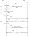
이하 도 9을 참조하여 4단계 랜덤 액세스 절차(4-step RACH procedure)를 상세히 설명한다. 도 9을 참조하면, 랜덤 액세스 절차의 제 1 단계(901)로서 단말은 랜덤 액세스 프리앰블(random access preamble)을 기지국으로 전송한다. 그러면 기지국은 단말과 기지국 사이의 전송 지연값을 측정하고, 상향링크 동기를 맞춘다. 이 때 단말은 어떤 랜덤 액세스 프리앰블을 사용할지는 사전에 시스템 정보에 의해 주어진 랜덤 액세스 프리앰블 세트 내에서 임의로 선택한다. 그리고 랜덤 액세스 프리앰블의 초기 전송전력은 단말이 측정한 기지국과 단말 사이의 경로손실(pathloss)에 따라 결정한다. 또한 단말은 기지국으로부터 수신한 동기신호로부터 랜덤 액세스 프리앰블의 송신 빔 방향을 결정해서 랜덤 액세스 프리앰블을 전송한다.Hereinafter, referring to FIG. 9, a 4-step random access procedure (4-step RACH procedure) will be described in detail. Referring to FIG. 9, as a
제2 단계(902)에서 기지국은 제1 단계에서 수신한 랜덤 액세스 프리앰블로부터 측정한 전송지연 값으로부터 단말에게 상향링크 전송 타이밍 조절 명령을 전송한다. 또한 기지국은 스케쥴링 정보로서 단말이 사용할 상향 링크 자원 및 전력제어 명령을 전송한다. 상기 스케쥴링 정보에 단말의 상향링크 송신 빔에 대한 제어정보가 포함될 수 있다.In
만약 단말이 제2 단계(902)에서 message 3 에 대한 스케쥴링 정보인 랜덤 액세스 응답 (Random Access Response; RAR, message 2)을 기지국으로부터 소정의 시간 동안 수신하지 못하면, 제1 단계(901)를 다시 진행한다. 만약 상기 제 1 단계를 다시 진행하는 경우, 단말은 랜덤 액세스 프리앰블의 전송전력을 소정의 스텝만큼 증가 시켜서 전송함으로써 (power ramping), 기지국의 랜덤 액세스 프리앰블 수신확률을 높인다.If the terminal does not receive a Random Access Response (RAR, message 2), which is scheduling information for
제3 단계(903)에서 단말은 기지국에게 자신의 단말 아이디를 포함한 상향링크 데이터(message 3)를 제2 단계(902)에서 할당 받은 상향링크 자원을 사용해 상향링크 데이터 채널 (PUSCH; Physicla Uplink Shared Channel)을 통해 전송한다. Message 3 를 전송하기 위한 상향링크 데이터채널의 전송타이밍은 제2 단계(902)에서 기지국으로부터 수신한 타이밍 제어 명령을 따른다. 그리고 Message 3 를 전송하기 위한 상향링크 데이터채널의 전송전력은 제2 단계(902)에서 기지국으로부터 수신한 전력제어 명령과 랜덤 액세스 프리앰블의 파워램핑 값을 고려해서 결정한다. 상기 Message 3 를 전송하기 위한 상향링크 데이터채널은 단말이 랜덤 액세스 프리앰블 전송 이후, 단말이 기지국으로 전송하는 최초의 상향링크 데이터 신호이다.In step 3 (903), the terminal transmits uplink data (message 3) including its own terminal ID to the base station using the uplink resources allocated in step 2 (902). ) is sent via Transmission timing of the uplink data channel for transmitting
마지막으로 제4 단계(904)에서 기지국은 단말이 다른 단말과 충돌 없이 랜덤 액세스를 수행한 것으로 판단되면, 제3 단계(903)에서 상향링크 데이터를 전송한 단말의 아이디를 포함하는 데이터(message 4)를 해당 단말에게 전송한다. 단말은 기지국으로부터 제4 단계(904)에서 기지국이 전송한 신호가 수신되면, 랜덤 액세스가 성공했음을 판단한다. 그리고 단말은 상기 message 4 에 대한 성공적인 수신 여부를 나타내는 HARQ-ACK/NACK 을 상향링크 제어채널 (PUCCH; Physical Uplink Control Channel)을 통해서 기지국으로 전송한다.Finally, in step 4 (904), when the base station determines that the terminal has performed random access without collision with other terminals, in step 3 (903), the base station sends data (message 4) including the ID of the terminal that has transmitted uplink data. ) is transmitted to the corresponding terminal. When the terminal receives the signal transmitted by the base station in
만일 단말이 제3 단계(903)에서 전송한 데이터와 다른 단말의 데이터가 서로 충돌하여 기지국이 단말로부터의 데이터 신호 수신에 실패하면, 기지국은 단말에게 더 이상의 데이터 전송을 하지 않는다. 이에 단말은 일정 시간 구간 동안 기지국으로부터 제4 단계(904)에서 전송되는 데이터 수신을 하지 못하면, 랜덤 액세스 절차 실패로 판단하고, 제 1 단계(901)부터 다시 시작한다.If the base station fails to receive a data signal from the terminal because data transmitted by the terminal in
상기와 같이 4단계 랜덤액세스 절차는 많은 시그날링 절차가 요구된다. 따라서 차세대 이동 통신 시스템에서는 더 적은 시그날링 절차로 단말은 connected 상태로 전환하고, 기지국과 단말 사이에 일대일 통신이 가능하게 되는 2단계 랜덤액세스 절차 (2-step RACH procedure)를 새로 정의 할 수 있다.As described above, the 4-step random access procedure requires many signaling procedures. Therefore, in the next-generation mobile communication system, a 2-step random access procedure (2-step RACH procedure) can be newly defined in which a terminal is switched to a connected state with fewer signaling procedures and one-to-one communication between the base station and the terminal is possible.
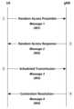
도 10처럼 상기와 같은 새로운 절차에서는 단말이 기지국에게 기존 절차의 1 단계인 랜덤 액세스 프리앰블과 3 단계인 자신의 단말 아이디를 포함한 상향링크 데이터 (message 3)를 동시에 전송한다(1001). 기지국은 상기 신호를 수신한 후 단말에게 상향링크 전송 타이밍 조절 명령이 포함된 2 단계와 랜덤 액세스 성공을 판단하는 신호 4단계를 동시에 전송 함으로써(1002) 더 적은 시그날링 절차로 더 빠르게 접속하고 데이터를 송수신할 수 있다.As shown in FIG. 10, in the above new procedure, the terminal simultaneously transmits the random access preamble, which is
이 때, 2단계 랜덤액세스 절차를 NOMA를 통해 전송하게 된다면 랜덤액세스의 특성상 동시에 여러 단말이 접속 할 수 있는데 message 3에 해당하는 데이터를 여러 단말이 동일한 물리적 자원에서 다른 MA 시그니쳐를 사용함으로써 동시에 전송 할 수 있어 수 많은 단말을 위한 자원을 할당 해 줄 필요 없이 훨씬 효율적으로 전송 할 수 있다.At this time, if the two-step random access procedure is transmitted through NOMA, several terminals can access at the same time due to the nature of random access. Therefore, transmission can be performed much more efficiently without the need to allocate resources for numerous terminals.
하지만 상기 랜덤액세스 절차에서 4단계 랜덤 액세스 절차의 1단계와 3단계를 동시에 전송하기 때문에 message 3 (PUSCH)를 전송하기 위해 필요한 다양한 파라미터들(상향 링크 자원 및 전력제어 명령, MCS, 주파수 호핑 등)을 수신할 수 없기 때문에 4단계 랜덤액세스와는 다른 방법으로 상기 파라미터 정보를 수신하거나 혹은 default 값을 정해야 한다. 특히, NOMA를 통해 프리엠블과 meassage3를 동시에 전송하는 경우 단말들이 동일한 MA 시그니쳐 사용에 따라 충돌이 발생 할 수 있기 때문에 단말들이 각각 다른 MA 시그니쳐를 사용하여 랜덤액세스 절차를 수행해야 한다. 하지만 RRC 비활성화 모드에 있는 단말은 CONNECTED 모드에서 사용한 MA 시그니쳐 정보를 갖고 있지만 기지국에서 구별할 수 있는 MA 시그니쳐 개수는 한정되어 있기 때문에 기지국에서 CONNECTED 모드에 있는 단말들을 효율적으로 더 많은 수를 지원하기 위하여 RRC 비활성화 모드로 전환된 단말이 사용했던 MA 시그니쳐를 CONNECTED 모드에 있는 단말에게 할당 할 수 있다. 이 때, RRC 비활성화 모드에 있는 단말이 RRC 연결 재개를 위해 NOMA를 이용한 2단계 랜덤액세스 절차를 수행하는 경우 프리엠블과 데이터(message 3)를 동시에 전송하기 위하여 기존 CONNECTED 모드에서 사용한 MA 시그니쳐를 사용해서 전송할 수 있다. 이 경우 CONNECTED 모드에서 동일한 MA 시그니쳐를 사용하고 있는 단말과 충돌이 발생 할 수 있으며, 또한 CONNECTED 모드에서 다른 시간대에 동일한 MA 시그니쳐를 사용했지만 마찬가지로 RRC 비활성화 모드로 전환된 단말들이 다시 CONNECTED 모드로 전환하고 싶을 때 충돌이 발생 할 수 있다.However, since
도 11a과 11b는 상기 설명을 나타내는 예제 이다. 도 11a에서 단말 1이 MA 시그니쳐 1을 사용하다가(11a-01) RRC 비활성화 모드로 전환된 경우(11a-02), 기지국은 새로운 단말 K+1을 지원하기 위하여 RRC 비활성화 모드로 전환된 단말 1이 사용 했던 MA 시그니쳐 1(11a-11)을 사용하라고 할당 할 수 있다. 이 때 단말 1이 다시 RRC 비활성화 모드에서 RRC 연결 재개를 위해 NOMA를 이용한 2단계 랜덤액세스 절차를 수행하는 경우 프리엠블과 데이터(message 3)를 동시에 전송하기 위하여 기존 CONNECTED 모드에서 사용한 MA 시그니쳐 1을 사용해서 전송하는 경우 CONNECTED 모드에서 동일한 MA 시그니쳐를 사용하고 있는 단말 K+1과 충돌이 발생 할 수 있다.11A and 11B are examples illustrating the above description. In FIG. 11a, when
다른 예제로 도 11b에서 처럼 단말1부터 단말 k가 CONNECTED 모드에서는 다른 시간대에서 모두 MA 시그니쳐 1을 사용(11b-01, 11b-02, 11b-03)하였고 RRC 비활성화 모드로 전환 된 경우(11b-11, 11b-12, 11b-13) RRC 비활성화 모드로 전환된 단말들이 다시 CONNECTED 모드로 전환하고 싶은 시간대가 겹칠 경우 기존 CONNECTED 모드에서 사용한 MA 시그니쳐 1을 사용하는 경우 충돌이 발생 할 수 있다.As another example, as shown in FIG. 11b, when terminal 1 to terminal k use MA signature 1 (11b-01, 11b-02, 11b-03) in CONNECTED mode in different time zones and switch to RRC inactive mode (11b-11 , 11b-12, 11b-13) When terminals switched to RRC inactive mode overlap with the time zones in which they want to switch back to CONNECTED mode, a collision may occur when using
따라서, 본 개시의 일 실시예에서는 단말이 RRC 비활성화 모드에서 RRC 연결 재개를 위해 NOMA를 이용한 2단계 랜덤액세스 절차를 수행하는 경우 단말간 충돌을 줄이기 위해 MA 시그니쳐를 선택하는 방안을 제안한다.Therefore, in an embodiment of the present disclosure, when a UE performs a two-step random access procedure using NOMA to resume an RRC connection in an RRC inactive mode, a method of selecting an MA signature is proposed to reduce collision between UEs.
MA 시그니쳐를 선택하는 방법으로 하기의 방법들이 고려될 수 있다.As a method of selecting an MA signature, the following methods may be considered.
[방법 1][Method 1]
상기 설명처럼 기지국이 상기 단말을 RRC 비활성화 모드로 천이시켜야 할 필요가 생기면 기지국은 suspend 설정 정보(suspendConfig)를 포함하는 상위 계층 시그널링 RRC 연결 해제 메시지(RRCRelease 메시지)(805)를 보내어 단말을 RRC 비활성화 모드로 천이시킬 수 있다. 이 때, 기지국은 RRC 연결 해제 메시지 (RRCRelease 메시지)를 통해 단말이 RRC 비활성화 모드에서 RRC 연결 모드로 전환하기 위한 2단계 랜덤 액세스 절차에서 사용할 MA 시그니쳐를 명시적으로 설정해 줄 수 있다.As described above, if the base station needs to transition the terminal to the RRC inactive mode, the base station sends an upper layer signaling RRC connection release message (RRCRelease message) 805 including suspend configuration information (suspendConfig) to the terminal in the RRC inactive mode. can be transitioned to At this time, the base station may explicitly set the MA signature to be used in the 2-step random access procedure for the terminal to switch from the RRC inactive mode to the RRC connected mode through an RRC connection release message (RRCRelease message).
[방법 2][Method 2]
상기 설명처럼 기지국이 상기 단말을 RRC 비활성화 모드로 천이시켜야 할 필요가 생기면 기지국은 suspend 설정 정보(suspendConfig)를 포함하는 상위 계층 시그널링 RRC 연결 해제 메시지(RRCRelease 메시지)(805)를 보내어 단말을 RRC 비활성화 모드로 천이시킬 수 있다. 이 때, 기지국은 RRC 연결 해제 메시지 (RRCRelease 메시지)에 포함된 I-RNTI 값을 기반으로 다음과 같은 수식으로 단말에게 MA 시그니쳐 인덱스
[수식 1][Formula 1]

상기 수식에서I-RNTI 는 상기 설명처럼 RRC 연결 해제 메시지에 포함된 값으로 기지국이 RRC 비활성화 모드로 전환되는 단말에게 지정해주는 값이다. 또한
[방법 3][Method 3]
상기 설명처럼 기지국이 상기 단말을 RRC 비활성화 모드로 천이시켜야 할 필요가 생기면 기지국은 suspend 설정 정보(suspendConfig)를 포함하는 상위 계층 시그널링 RRC 연결 해제 메시지(RRCRelease 메시지)(805)를 보내어 단말을 RRC 비활성화 모드로 천이시킬 수 있다. 이 때, 기지국은 RRC 연결 해제 메시지 (RRCRelease 메시지)에 포함된 I-RNTI 값을 기반으로 다음과 같은 수식으로 단말에게 MA 시그니쳐 pool의 인덱스
[수식 2][Formula 2]

상기 수식에서I-RNTI 는 상기 설명처럼 RRC 연결 해제 메시지에 포함된 값으로 기지국이 RRC 비활성화 모드로 전환되는 단말에게 지정해주는 값이다. 또한
[방법 4] [Method 4]
상기 설명처럼 기지국이 상기 단말을 RRC 비활성화 모드로 천이시켜야 할 필요가 생기면 기지국은 suspend 설정 정보(suspendConfig)를 포함하는 상위 계층 시그널링 RRC 연결 해제 메시지(RRCRelease 메시지)(805)를 보내어 단말을 RRC 비활성화 모드로 천이시킬 수 있다. 이 때, 기지국은 RRC 연결 해제 메시지 (RRCRelease 메시지)에 포함된 I-RNTI 값을 기반으로 다음과 같은 수식으로 단말에게 데이터 전송 자원의 인덱스
[수식 3][Formula 3]

상기 수식에서I-RNTI 는 상기 설명처럼 RRC 연결 해제 메시지에 포함된 값으로 기지국이 RRC 비활성화 모드로 전환되는 단말에게 지정해주는 값이다. 또한
이 수식을 통해 기존에 RRC 시그널링의 추가 혹은 변경 없이 기지국이 단말에게 인덱스를 지시할 수 있고 이를 기반으로 단말은 RRC 비활성화 모드에서 CONNECTED 모드로 전환할 때 랜덤액세스 절차에서 지시된 물리적 자원(주파수 및 시간 자원)에서 RRC 비활성화 모드로 전환되기 전에 CONNECTED 모드에서 사용한 MA 시그니쳐를 기반으로 프리엠블 및 데이터를 전송 할 수 있다.Through this formula, the base station can indicate the index to the terminal without adding or changing the existing RRC signaling, and based on this, the physical resources (frequency and time) indicated in the random access procedure when the terminal switches from the RRC inactive mode to the CONNECTED mode resource) before switching to RRC inactive mode, preamble and data can be transmitted based on the MA signature used in CONNECTED mode.
상기 방법 1, 방법 2, 방법 3, 방법 4에서는 기지국이 각 단말이 RRC 비활성화 모드로 전환 되는 경우에 RRC 비활성화 모드에서 사용할 MA 시그니쳐를 할당 해주기 때문에 효율적으로 할당해 줄 수 있다. 또한 동적으로 MA 시그니쳐를 변경 할 수 있기 때문에 지원해야 하는 단말들의 수가 급격히 증가하거나 환경이 급격히 변경되었을 때 효율적으로 사용할 수 있다. 예를 들어, 여러 단말이 동시에 RRC 비활성화 모드에서 CONNECTED 모드로 전환하는 경우는 확률적으로 적기 때문에 기지국이 RRC 비활성화 모드에서 사용할 MA 시그니쳐를 RRC 비활성화 모드에 있는 단말들의 수보다 적게 할당 해주고 CONNECTED 모드에 있는 단말들에게 더 많이 할당 해 줄 수 있으며 기지국이 단말의 수에 따라 혹은 상황에 따라 단말 각각에게 할당 해줄 수 있어 효율적으로 할당 해 줄 수 있다.In
[방법 5][Method 5]
단말은 RRC 비활성 모드에서 CONNECTED 모드로 전환할 때 2단계 랜덤 액세스 절차에서 데이터 전송에 사용하는 MA 시그니쳐 혹은 MA 시그니쳐 pool을 CONNECTED 모드에서 사용하는 MA 시그니쳐 혹은 MA 시그니쳐 pool과는 별개로 CONNECTED 모드에서 RRC 시그널링 혹은 L1 시그널링을 통해 명시적으로 할당 받을 수 있다. 상기 방법의 경우 어떤 단말들이 RRC 비활성 모드로 변경될지 모르기 때문에 동적으로 RRC 비활성 모드로 전환될 때 단말에게 알려주는 방법 1, 방법 2, 방법 3, 방법 4와는 다르게 반정적(semi-static)으로 알려주기 때문에 상기 방법들과 비교해서 비효율적으로 MA 시그니쳐들이 사용될 수 있다.When the UE switches from RRC inactive mode to CONNECTED mode, the MA signature or MA signature pool used for data transmission in the second-step random access procedure is different from the MA signature or MA signature pool used in CONNECTED mode. Alternatively, it may be explicitly allocated through L1 signaling. In the case of the above method, since it is not known which terminals will change to the RRC inactive mode, it is notified in a semi-static manner, unlike
[방법 6][Method 6]
단말은 RRC 비활성 모드에서 CONNECTED 모드로 전환할 때 2단계 랜덤 액세스 절차에서 데이터 전송에 사용하는 MA 시그니쳐 혹은 MA 시그니쳐 pool을 시스템 정보를 통해 명시적으로 설정해 줄 수 있다. 시스템 정보는 RRC 유휴 모드와 RRC 비활성 모드에 있는 모든 단말들이 공통으로 받기 때문에 여러 단말이 동시에 같은 MA 시그니쳐를 선택하여 전송하기 때문에 충돌이 날 확률이 증가한다. 또한 동적으로 MA 시그니쳐를 변경 할 수 없기 때문에 지원해야 하는 단말들의 수가 급격히 증가하거나 환경이 급격히 변경되었을 때 변경하기 쉽지 않다. 하지만 단말들의 수가 급격히 변하지 않는 환경에서는 시스템 정보를 기반으로 공통적으로 단말들이 MA 시그니쳐를 선택 할 수 있다.When switching from RRC inactive mode to CONNECTED mode, the UE can explicitly set the MA signature or MA signature pool used for data transmission in the 2-step random access procedure through system information. Since system information is commonly received by all terminals in RRC idle mode and RRC inactive mode, the probability of collision increases because several terminals select and transmit the same MA signature at the same time. In addition, since the MA signature cannot be dynamically changed, it is not easy to change it when the number of terminals to be supported increases rapidly or the environment changes rapidly. However, in an environment in which the number of terminals does not change rapidly, terminals may commonly select an MA signature based on system information.
전술한 방법 1, 방법 2, 방법 3, 방법 4, 방법 5, 방법 6은 서로 조합되어 운용될 수 있다.
본 개시의 제 1 실시예를 통해 각 단말은 RRC 비활성화 모드에서 2단계 랜덤액세스 절차를 수행할 때 NOMA를 통해 여러 단말들이 데이터를 같은 자원에서 하여도 충돌을 줄일 수 있는 MA 시그니쳐 혹은 MA 시그니쳐 pool를 지시 받을 수 있다. 기지국은 미리 각 단말이 RRC 비활성화 모드에서 어떤 MA 시그니쳐를 사용 하는지 판단 할 수 있고, 이에 따라 NOMA에서 각 단말의 PUSCH 전송 여부를 판단하는데 요구되는 복잡도를 최소화할 수 있다.Through the first embodiment of the present disclosure, when each terminal performs a two-step random access procedure in the RRC inactive mode, an MA signature or an MA signature pool that can reduce collision even when multiple terminals transmit data in the same resource through NOMA can be instructed. The base station can determine in advance which MA signature each terminal uses in the RRC inactive mode, and accordingly, complexity required for determining whether each terminal transmits the PUSCH in NOMA can be minimized.
<제 2 실시 예><Second Embodiment>
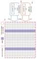
기지국이 단말에게 다중 PUSCH들이 같은 시간 인덱스를 갖는 심볼에서 일부 또는 전체 주파수 대역을 공유하여 다중 상향 데이터를 전송하도록 물리 신호(예를 들어, DCI)들 혹은 상위 계층 신호(예를 들어, RRC 시그널링)에 의해 지시되었을 경우, NOMA를 통해 여러 데이터를 동시에 전송 할 수 있는 방법에 대해서 서술한다. 상기 환경에 관련된 하나의 예는 하기와 같다.Physical signals (eg, DCI) or higher layer signals (eg, RRC signaling) so that the base station transmits multiple uplink data by sharing some or all frequency bands in symbols having the same time index in multiple PUSCHs to the terminal. If indicated by , describes how to transmit multiple data simultaneously through NOMA. One example related to the environment is as follows.
도 12처럼 기지국이 단말에게 URLLC 서비스 데이터를 전송하는 용도로 준정적(semi-static)인 시간/주파수 자원(1202)을 상위 계층 시그널링 (RRC 시그널링)으로 설정 할 수 있다. 단말은 기지국으로 전송하고자 하는 URLLC 트래픽(1210)이 발생하였을 경우 비승인 기반 전송 방식으로 URLLC 트래픽(1210)을 전송한다. 이 때, 단말은 시간/주파수 자원이 많이 필요한 eMBB 서비스 데이터를 기지국으로 전송하고자 하는 경우, 기지국으로 스케쥴링 요청 메시지를 상향링크 제어채널로 전송한다. 스케쥴링 요청 메시지를 수신한 기지국은 해당 단말에게 스케쥴링 승인에 해당하는 상향링크 스케쥴링 DCI(1220)를 전송할 수 있다. 기지국은 스케쥴링 DCI(1220)를 기반으로 단말이 특정 여러 심볼에서 PUSCH를 통해 eMBB 서비스에 해당하는 상향 데이터를 전송하도록 지시 할 수 있다(1201). 이 경우, 상기 특정 여러 심볼과 같은 시간 인덱스를 갖는 심볼에서 단말이 URLLC 서비스에 해당하는 비승인 기반 상향 데이터를 전송해야 할 상황이 발생하였을 경우(1230), 이미 단말이 eMBB 데이터를 스케줄링된 자원에서 전송하고 있는 주파수 대역에서 eMBB 데이터 일부를 전송하지 않고, 상기 발생한 URLLC 데이터를 상기 주파수 대역에서 전송할 수 있다. 이와 같은 경우 단말이 이미 스케줄링하여 전송하고 있던 eMBB 데이터 일부를 전송하지 않는 부분이 생기기 때문에 eMBB 데이터가 손상될 가능성이 크게 증가한다. 이를 해결 하기 위해 eMBB 데이터 일부 전송하지 않는 부분을 다시 재전송 하거나 혹은 eMBB 데이터 전체를 다시 재전송 하게되어 자원 및 시간 손실이 발생하게 된다.As shown in FIG. 12, the base station may set a semi-static time/frequency resource 1202 as higher layer signaling (RRC signaling) for the purpose of transmitting URLLC service data to the terminal. When the
상기와 같은 예에서 NOMA를 통해서 일부 또는 전체 주파수 대역을 공유하여 eMBB와 URLLC에 따른 정보가 스케줄링 될 때, 혹은 mMTC와 URLLC에 따른 정보가 동시에 스케줄링 될 때, 혹은 mMTC와 eMBB에 따른 정보가 동시에 스케줄링 될 때, 혹은 eMBB와 URLLC와 mMTC에 따른 정보가 동시에 스케줄링 될 때 각 서비스에 따른 정보를 전송할 수 있는 이종서비스간 공존 방법에 대해서 서술한다.In the above example, when information according to eMBB and URLLC is scheduled by sharing some or all frequency bands through NOMA, or information according to mMTC and URLLC is scheduled simultaneously, or information according to mMTC and eMBB is simultaneously scheduled When information according to eMBB, URLLC, and mMTC is scheduled at the same time, a coexistence method between heterogeneous services that can transmit information according to each service is described.
상기 설명처럼 NOMA를 통해서 다수의 단말들은 기지국으로부터 직접적 혹은 간접적으로 받은 서로 다른 MA 시그니쳐를 통해 동일한 시간 및 주파수 자원에서 자신의 PUSCH를 동시에 전송할 수 있다. 이는 하나의 단말 내 에서도 동일하게 적용될 수 있다. 도 13처럼 하나의 단말에서 서로 다른 MA 시그니쳐(1301, 1302)를 통해 동일한 시간 및 주파수 자원(1311)에서 상기 설명처럼 다른 서비스(eMBB, URLLC, mMTC)를 위한 다수의 PUSCH를 동시에 전송할 수 있다. 하지만 하나의 단말에서 다수의 PUSCH를 동시에 같은 자원에서 전송하는 것은 고려되어 있지 않기 때문에 하나의 PUSCH 스케쥴링에 하나의 제어 정보(예컨대, MCS(Modulation and Coding Scheme)정보와 전력 정보 등)가 포함되어지기 때문에 하기와 같은 문제가 발생한다.As described above, through NOMA, a plurality of terminals can simultaneously transmit their own PUSCHs in the same time and frequency resources through different MA signatures directly or indirectly received from the base station. This can be equally applied within one terminal. As shown in FIG. 13, a plurality of PUSCHs for different services (eMBB, URLLC, mMTC) can be simultaneously transmitted in one terminal through
기지국이 먼저 단말에게 비승인-기반 PUSCH 전송방식으로 스케쥴링을 지시한 경우에 하나의 PUSCH가 전송 될 것으로 고려되어 MCS(Modulation and Coding Scheme)정보가 결정 된다. 그 후, 승인-기반 PUSCH 전송방식으로 스케쥴링을 지시한 경우에도 비승인-기반 PUSCH 전송 방식에서는 단말이 기지국으로 전송하고자 하는 트래픽(Traffic)이 발생하였을 경우에만 설정된 시간/주파수 자원에서 기지국 승인 없이 바로 PUSCH를 전송하기 때문에 기지국은 승인-기반 PUSCH의 전송방식에서도 다수의 PUSCH에 전송 되는 것을 보장하여 MCS(Modulation and Coding Scheme)정보가 결정 될 수 없다. 이와 같은 경우 하나의 단말에서 다수의 PUSCH가 전송되는 경우 기지국은 상기 단말에서 하나의 PUSCH가 전송될 경우를 기반으로 MCS를 설정 해주었기 때문에 다수의 PUSCH가 전송될 때 기존 동일한 MCS기반으로 전송한다면 성능(reliability 등) 감소가 발생 할 수 있어 MCS 값을 조절 해주어야 할 수 있다.When the base station first instructs the terminal to perform scheduling in an unacknowledged-based PUSCH transmission scheme, it is considered that one PUSCH will be transmitted and Modulation and Coding Scheme (MCS) information is determined. After that, even when scheduling is instructed in the grant-based PUSCH transmission method, in the non-grant-based PUSCH transmission method, only when traffic to be transmitted to the base station by the terminal occurs, the time/frequency resource is set immediately without base station approval. Since the PUSCH is transmitted, the base station guarantees that multiple PUSCHs are transmitted even in the grant-based PUSCH transmission method, so that Modulation and Coding Scheme (MCS) information cannot be determined. In this case, when multiple PUSCHs are transmitted from one UE, the base station configures the MCS based on the case where one PUSCH is transmitted from the UE, so if multiple PUSCHs are transmitted based on the existing MCS, performance (reliability, etc.) may decrease, so the MCS value may need to be adjusted.
따라서, 본 개시의 일 실시예에서는 단말이 NOMA를 통해 다수의 PUSCH를 전송할 때 MCS(Modulation and Coding Scheme)정보를 선택하는 방법으로 하기의 방법들이 고려될 수 있다.Accordingly, in an embodiment of the present disclosure, the following methods may be considered as a method for selecting Modulation and Coding Scheme (MCS) information when a UE transmits multiple PUSCHs through NOMA.
[방법 1][Method 1]
상기 설명처럼 기지국이 단말에게 승인-기반 PUSCH 전송방식 혹은 비승인-기반 PUSCH 전송방식으로 스케쥴링을 지시하는 상위 계층 시그널링(RRC 시그널링) 혹은 L1 시그널링(DCI)에 각각 여러 개의 MCS 값을 명시적으로 지시할 수 있다. 이 때, 단말은 동시에 하나 혹은 다수개의 PUSCH를 전송하는지에 따라 각각 승인-기반과 비승인-기반 PUSCH 전송방식을 위한 각각의 MCS 값을 선택할 수 있다.As described above, the base station explicitly indicates several MCS values in higher layer signaling (RRC signaling) or L1 signaling (DCI) instructing the UE to schedule a grant-based PUSCH transmission method or a non-grant-based PUSCH transmission method. can do. At this time, the UE may select respective MCS values for grant-based and non-grant-based PUSCH transmission schemes depending on whether one or multiple PUSCHs are simultaneously transmitted.
[방법 2][Method 2]
기지국이 단말에게 상향링크 스케쥴링 DCI(예컨대 L1 시그널링) 혹은 상위 계층 시그널링(예컨대 RRC(Radio Resource Control) 시그널링)을 통해 PUSCH 전송을 설정할 수 있다. 이 때, 기지국은 단말에게 동시에 다중 PUSCH들이 같은 시간 인덱스를 갖는 심볼에서 일부 또는 전체 주파수 대역을 공유하여 다중 상향 데이터를 전송하도록 물리 신호(DCI)들 혹은 상위 계층 신호(RRC 시그널링)에 의해 지시되었을 경우, 시간적으로 나중에 지시하는 L1 시그널링 혹은 상위 계층 시그널링에 이전에 스케쥴링 된 PUSCH와 관련된 MCS 값과 상기 시그널링을 통해 지시되는 PUSCH와 관련된 MCS값을 포함하여 명시적으로 지시할 수 있다. 좀 더 구체적으로, 기지국이 처음에 단말에게 상향 데이터 전송을 지시 하는 L1 시그널링 혹은 상위 계층 시그널링에는 같은 시간 인덱스를 갖는 심볼에서 단말이 하나의 PUSCH만을 전송하는 것을 알기 때문에 하나의 MCS 정보를 전달 해줄 수 있다. 그 다음 기지국이 단말에게 추가적으로 상기 첫 PUSCH와 같은 시간 인덱스를 갖는 심볼에서 상향 데이터 전송을 지시하는 L1시그널링 혹은 상위 계층 시그널링에는 단말이 하나 혹은 다중의 PUSCH를 전송할 수 있다는 것을 알기 때문에 추가적으로 지시하는 PUSCH의 MCS 정보뿐만 아니라 이전 PUSCH를 위한 추가적인 MCS 정보도 포함 할 수 있다.The base station may configure PUSCH transmission to the terminal through uplink scheduling DCI (eg, L1 signaling) or higher layer signaling (eg, radio resource control (RRC) signaling). At this time, the base station is instructed by physical signals (DCI) or higher layer signals (RRC signaling) to transmit multiple uplink data by sharing some or all frequency bands in symbols having the same time index on multiple PUSCHs at the same time. In this case, it may be explicitly indicated by including an MCS value related to a previously scheduled PUSCH in L1 signaling or higher layer signaling indicated later in time and an MCS value related to the PUSCH indicated through the signaling. More specifically, since the base station knows that the terminal transmits only one PUSCH in a symbol having the same time index in L1 signaling or higher layer signaling that initially instructs the terminal to transmit uplink data, it can deliver one MCS information. there is. Then, since the base station knows that the terminal can transmit one or multiple PUSCHs in L1 signaling or higher layer signaling in which the base station additionally instructs the terminal to transmit uplink data in a symbol having the same time index as the first PUSCH, In addition to MCS information, additional MCS information for the previous PUSCH may be included.
[방법 3][Method 3]
기지국과 단말이 서로 약속된 정보를 기반으로 단말은 동시에 하나 혹은 다수개의 PUSCH를 전송하는지에 따라 각각 승인-기반과 비승인-기반 PUSCH 전송방식을 위한 각각의 MCS 값을 계산하여 선택할 수 있다. 예를 들어, 기존에 지시된 MCS 인덱스에서 추가적인 PUSCH를 전송해야 하는 경우에 동시에 전송하는 PUSCH 수에 따라 단말은 MCS 인덱스를 계산 후 선택한다. 동시에 전송하는 PUSCH 수가 2개인 경우 각 PUSCH에 지시받은 MCS 인덱스에서 한단계 낮은 인덱스를 선택한다. 이는 다음과 같은 수식으로 표현될 수 있다.Based on information agreed between the base station and the terminal, the terminal may calculate and select respective MCS values for grant-based and non-grant-based PUSCH transmission schemes depending on whether one or multiple PUSCHs are simultaneously transmitted. For example, when an additional PUSCH needs to be transmitted in a previously indicated MCS index, the UE calculates and selects the MCS index according to the number of simultaneously transmitted PUSCHs. When the number of simultaneously transmitted PUSCHs is two, an index lower by one step is selected from the MCS index indicated for each PUSCH. This can be expressed in the following formula.
[수식 4][Formula 4]

상기 수식에서


본 개시의 제 2 실시예를 통해 단말은 같은 시간 인덱스를 갖는 심볼에서 일부 또는 전체 주파수 대역을 공유하여 다중 상향 데이터를 전송할 때 발생할 수 있는 성능 감소 혹은 환경 변화를 고려하여 MCS를 수정 할 수 있다.Through the second embodiment of the present disclosure, the terminal can modify the MCS in consideration of performance degradation or environmental change that may occur when transmitting multi-uplink data by sharing a part or the entire frequency band in a symbol having the same time index.
<제 2-1 실시 예><Example 2-1>
상기 제 2실시 예처럼 하나의 단말이 여러 상위 시그널링 혹은 L1 시그널링을 통해 같은 시간 인덱스를 갖는 심볼에서 일부 또는 전체 주파수 대역을 공유하여 다중 상향 데이터 전송을 지시 받았을 때, 각각의 상위 시그널링 혹은 L1 시그널링은 하나의 단말에서 다수의 PUSCH를 동시에 같은 자원에서 전송하는 것은 고려되어 있지 않기 때문에 하나의 PUSCH 스케쥴링에 하나의 전력 정보가 포함되어지기 때문에 하기와 같은 문제가 발생한다.As in the second embodiment, when one UE is instructed to transmit multiple uplink data by sharing some or all frequency bands in a symbol having the same time index through several higher-order signaling or L1 signaling, each higher-order signaling or L1 signaling Since transmission of a plurality of PUSCHs on the same resource at the same time in one UE is not considered, the following problem occurs because one power information is included in one PUSCH scheduling.
기지국이 먼저 단말에게 비승인-기반 PUSCH 전송방식으로 스케쥴링을 지시한 경우에 하나의 PUSCH가 전송 될 것으로 고려되어 전력 정보가 결정 된다. 그 후, 승인-기반 PUSCH 전송방식으로 스케쥴링을 지시한 경우에도 비승인-기반 PUSCH 전송 방식에서는 단말이 기지국으로 전송하고자 하는 트래픽(Traffic)이 발생하였을 경우에만 설정된 시간/주파수 자원에서 기지국 승인 없이 바로 PUSCH를 전송한다. 따라서 기지국은 승인-기반 PUSCH의 전송방식에서도 다수의 PUSCH에 전송 되는 것을 보장하여 전력 정보를 결정할 수 없다. 이와 같은 경우 하나의 단말에서 다수의 PUSCH가 전송될 때, 기지국은 상기 단말에서 하나의 PUSCH가 전송될 경우를 기반으로 전력을 설정 해주었기 때문에 다수의 PUSCH가 전송될 때 기존 동일한 전력으로 전송한다면 다수의 PUSCH를 위한 전력의 합이 한 단말이 전송 할 수 있는 최대 전력을 초과 할 수 있으므로 단말은 전력을 조절해야 한다.When the base station first instructs the terminal to perform scheduling in an unlicensed-based PUSCH transmission scheme, power information is determined considering that one PUSCH is transmitted. After that, even when scheduling is instructed in the grant-based PUSCH transmission method, in the non-grant-based PUSCH transmission method, only when traffic to be transmitted to the base station by the terminal occurs, the time/frequency resource is set immediately without base station approval. Transmit PUSCH. Therefore, the base station cannot determine power information by guaranteeing transmission on multiple PUSCHs even in the grant-based PUSCH transmission scheme. In this case, when multiple PUSCHs are transmitted from one terminal, the base station sets the power based on the case in which one PUSCH is transmitted from the terminal, so if multiple PUSCHs are transmitted with the same power as before, multiple PUSCHs are transmitted. Since the sum of the powers for PUSCH can exceed the maximum transmittable power of one UE, the UE must adjust the power.
이 때, URLLC와 같이 높은 요구사항(초고신뢰도, 초저지연)을 요구하는 서비스 타입에 해당하는 트래픽에 대하여, 해당 요구사항을 만족시키기 위해, eMBB 또는 mMTC에 해당하는 트래픽에 비해 높은 우선순위를 두고 처리할 수 있다. 즉, 낮은 우선순위를 갖는 트래픽부터 전력을 조절 하여 우선 순위가 높은 트래픽에 대하여 요구사항을 만족시킬 수 있다.At this time, traffic corresponding to a service type requiring high requirements (ultra high reliability, ultra low latency) such as URLLC is given a higher priority than traffic corresponding to eMBB or mMTC in order to satisfy the corresponding requirements. can be dealt with That is, it is possible to satisfy the requirements for high-priority traffic by controlling power from traffic with low priority.
본 발명에서는 상대적으로 높은 우선순위가 필요한 서비스에 해당하는 트래픽을 “제1트래픽”, 상대적으로 낮은 우선순위를 갖는 서비스에 대한 트래픽을 “제2트래픽”으로 명명하도록 한다. 예를 들면, URLLC는 제1트래픽에 해당할 수 있고, eMBB 또는 mMTC는 제2트래픽에 해당할 수 있다. 또는 기지국의 판단 하에 제1트래픽과 제2트래픽을 구분하여 단말에게 통지할 수 있다. 물리계층에서 단말이 제1트래픽 또는 제2트래픽을 구분할 수 있다면, 그에 따라 다양한 물리계층 채널의 송수신에 있어서 서로 다른 우선 순위, 즉 제1트래픽에 보다 높은 우선 순위를 적용하여 처리할 수 있는 장점이 있다. 여기서 높은 우선 순위를 적용하여 처리한다는 것은, 제1트래픽과 제 2트래픽에 해당하는 데이터 채널, 참조 신호 등을 동시에 전송하는데 있어서 제1트래픽의 전력은 기지국으로부터 지시 받은 그대로 고정시키는 것을 의미한다. 그리고 제 2트래픽을 위해 지시 받은 전력과 단말이 최대로 전송할 수 있는 전력에서 상기 제 1트래픽 전송을 위해 지시 받은 전력을 제외한 남은 전력과 비교해서 더 적은 전력으로 제 2트래픽을 전송할 수 있다. 다음과 같은 수식으로 표현될 수 있다.In the present invention, traffic corresponding to a service requiring a relatively high priority is referred to as “first traffic” and traffic for a service having a relatively low priority is referred to as “second traffic”. For example, URLLC may correspond to the first traffic, and eMBB or mMTC may correspond to the second traffic. Alternatively, the base station may classify the first traffic and the second traffic under the determination and notify the terminal. If the terminal can distinguish the first traffic or the second traffic in the physical layer, there is an advantage in that different priorities in transmission and reception of various physical layer channels can be processed by applying a higher priority to the first traffic. there is. Here, processing by applying a high priority means fixing the power of the first traffic as instructed by the base station in simultaneously transmitting data channels and reference signals corresponding to the first and second traffic. In addition, the second traffic can be transmitted with less power compared to the power indicated for the second traffic and the remaining power excluding the power indicated for transmitting the first traffic from the maximum transmittable power of the terminal. It can be expressed in the following formula.
[수식 5][Formula 5]

상기 수식에서 Pmax는 단말이 전송할 수 있는 최대 전력을 나타내고, P1은 우선순위가 높은 제 1트래픽 전송을 위해 지시된 전력, P2는 우선순위가 낮은 제 2트래픽 전송을 위해 지시된 전력을 나타낸다. 마지막으로 P2,new는 우선순위가 낮은 제 2트래픽 전송을 위해 조절된 전력을 나타낸다.In the above formula, Pmax represents the maximum power that can be transmitted by the terminal, P1 is the power indicated for transmitting the first traffic having a high priority, and P2 represents the power indicated for transmitting the second traffic having a low priority. indicate Finally, P2,new indicates power adjusted for transmission of second traffic having a lower priority.
따라서, 단말이 물리 계층에서 현재 송수신하고자 하는 채널이 제1트래픽에 해당하는 채널인지의 여부를 인지할 수 있는 것이 중요하다. 본 발명의 제 2-1 실시 예에 따라 단말은 하기의 방법들 중 적어도 하나 또는 복수 개 또는 복수 개의 조합으로 제1트래픽을 구분할 수 있고 제 1트래픽의 지시 받은 전력은 고정하고 우선 순위가 낮은 트래픽의 전력을 조절한다.Therefore, it is important for the terminal to be able to recognize whether a channel to be currently transmitted/received in the physical layer is a channel corresponding to the first traffic. According to the 2-1 embodiment of the present invention, the terminal may classify the first traffic by at least one of the following methods, a plurality of methods, or a combination of a plurality of methods, the indicated power of the first traffic is fixed, and traffic having a low priority adjust the power of
[방법 1][Method 1]
제1트래픽에 해당하는 데이터채널을 스케쥴링하는 DCI가 특정 RNTI(예를 들어 C1-RNTI)로 스크램블링 될 수 있다. 단말은 기지국으로부터 C1-RNTI를 할당받을 수 있고, C1-RNTI로 스크램블링 된 DCI로 스케쥴링되는 데이터채널은 제1트래픽에 해당한다고 판단할 수 있다.A DCI scheduling a data channel corresponding to the first traffic may be scrambled with a specific RNTI (eg, C1-RNTI). The terminal may be allocated C1-RNTI from the base station, and may determine that a data channel scheduled with a DCI scrambled with the C1-RNTI corresponds to the first traffic.
[방법 2][Method 2]
제1트래픽에 해당하는 데이터채널을 스케쥴링하는 DCI가 특정 포맷(예를 들어 상향링크에 대하여 DCI 포맷 0-2 또는 하향링크에 대하여 DCI 포맷 1-2)으로 정의될 수 있다. 단말은 기지국으로부터 DCI 포맷 0-2/1-2를 모니터링하라는 설정을 통지받을 수 있고, 설정에 따라 DCI 포맷 0-2/1-2를 모니터링할 수 있다. 단말은 DCI 포맷 0-2/1-2로 스케쥴링되는 데이터채널은 제1트래픽에 해당한다고 판단할 수 있다.DCI scheduling a data channel corresponding to the first traffic may be defined in a specific format (eg DCI format 0-2 for uplink or DCI format 1-2 for downlink). The terminal may be notified of the setting to monitor the DCI format 0-2/1-2 from the base station, and may monitor the DCI format 0-2/1-2 according to the setting. The terminal may determine that the data channel scheduled in the DCI format 0-2/1-2 corresponds to the first traffic.
[방법 3][Method 3]
제1트래픽에 해당하는 데이터채널을 스케쥴링하는 DCI가 모니터링되는 탐색공간의 타입이 특정 탐색공간 타입(예를 들어 USS1)으로 정의될 수 있다. 단말은 기지국으로부터 탐색공간 타입이 USS1인 탐색공간을 설정 받을 수 있고, 탐색공간 타입이 USS1에 해당하는 탐색공간에서 검출된 DCI로 스케쥴링되는 데이터채널은 제1트래픽에 해당한다고 판단할 수 있다.A type of search space in which a DCI scheduling a data channel corresponding to the first traffic is monitored may be defined as a specific search space type (eg, USS1). The terminal may receive a search space of which the search space type is USS1 from the base station, and may determine that a data channel scheduled with a DCI detected in the search space having a search space type of USS1 corresponds to the first traffic.
[방법 4][Method 4]
제1트래픽에 해당하는 데이터채널을 스케쥴링하는 DCI가 모니터링되는 탐색공간이 특정 설정(이를 제1탐색공간설정으로 명명함)을 가질 수 있다. 제1탐색공간설정은 예를 들어 하기의 설정 정보들 중 적어도 하나 또는 복수 개를 포함할 수 있다.A search space in which a DCI scheduling a data channel corresponding to the first traffic is monitored may have a specific setting (this is referred to as a first search space setting). The first search space setting may include, for example, at least one or a plurality of items of the following setting information.
-가장 가까운 모니터링 occasion의 간격이 X (심볼) 이하에 해당하는 설정- Settings where the interval of the nearest monitoring occasion is less than X (symbol)
-슬롯 내 모니터링 occasion의 개수가 Y개 이상에 해당하는 설정- Settings where the number of monitoring occasions in a slot corresponds to Y or more
-탐색공간 ID(또는 인덱스)가 선정의 된 특정 값으로 지정- Search space ID (or index) is specified as a predefined value
-탐색공간 내 설정 파라미터로 제1트래픽 또는 제2트래픽의 여부를 명시적으로 설정- Explicitly set whether it is the first traffic or the second traffic as a setting parameter in the search space
단말은 기지국으로부터 제1탐색공간설정을 갖는 탐색공간을 설정 받을 수 있고, 해당 탐색공간에서 검출된 DCI로 스케쥴링되는 데이터채널은 제1트래픽에 해당한다고 판단할 수 있다.The terminal may receive a search space having a first search space setting from the base station, and may determine that a data channel scheduled with a DCI detected in the search space corresponds to the first traffic.
[방법 5][Method 5]
제1트래픽에 해당하는 데이터채널을 스케쥴링하는 DCI가 모니터링되는 제어영역이 특정 설정(이를 제1제어영역설정으로 명명함)을 가질 수 있다. 제1제어영역설정은 예를 들어 하기의 설정 정보들 중 적어도 하나 또는 복수 개를 포함할 수 있다.A control region in which a DCI scheduling a data channel corresponding to the first traffic is monitored may have a specific setting (this is referred to as a first control region setting). The first control area setting may include, for example, at least one or a plurality of items of the following setting information.
-제어영역 ID(또는 인덱스)가 선정의 된 특정 값으로 지정- Control area ID (or index) is designated as a predefined specific value
-제어영역 내 설정 파라미터로 제1트래픽 또는 제2트래픽의 여부를 명시적으로 설정- Explicitly set whether it is 1st traffic or 2nd traffic as a setting parameter in the control area
단말은 기지국으로부터 제1제어영역설정을 갖는 제어영역을 설정 받을 수 있고, 해당 탐색공간에서 검출된 DCI로 스케쥴링되는 데이터채널은 제1트래픽에 해당한다고 판단할 수 있다.The terminal may receive a control region having a first control region setting from the base station, and may determine that a data channel scheduled with a DCI detected in the corresponding search space corresponds to the first traffic.
[방법 6][Method 6]
기지국은 단말에게 제1트래픽에 해당하는 데이터채널이 스케쥴링될 수 있는 특정 대역폭부분(이를 제1대역폭부분으로 명명함)을 미리 설정할 수 있다. 제1대역폭부분은 예를 들어 하기의 설정 정보들 중 적어도 하나 또는 복수개를 포함할 수 있다.The base station may preset a specific bandwidth portion (referred to as a first bandwidth portion) in which a data channel corresponding to the first traffic can be scheduled to the UE. The first bandwidth part may include, for example, at least one or a plurality of items of the following setting information.
-대역폭부분의 부반송파간격이 선정의된 특정 값(X)보다 큰 값으로 설정될 수 있다.- The subcarrier spacing of the bandwidth part can be set to a value larger than a predefined specific value (X).
-대역폭부분의 ID(또는 인덱스)가 선정의 된 특정 값으로 지정- The ID (or index) of the bandwidth part is designated as a predefined specific value
-대역폭부분 내 설정 파라미터로 제1트래픽 또는 제2트래픽의 여부를 명시적으로 설정- Explicitly set whether the first traffic or the second traffic is a setting parameter in the bandwidth part
단말은 기지국으로부터 제1대역폭부분을 설정 받을 수 있고, 제1대역폭부분에서 검출된 DCI로 스케쥴링되는 데이터채널 또는 제1대역폭부분으로 스케쥴링된 데이터채널 또는 제1대역폭부분에서 검출된 DCI에 의해 제1대역폭부분으로 스케쥴링된 데이터채널은 제1트래픽에 해당한다고 판단할 수 있다.The terminal may receive a first bandwidth portion configured by the base station, and a data channel scheduled with the DCI detected in the first bandwidth portion or a data channel scheduled with the first bandwidth portion or a DCI detected in the first bandwidth portion may receive the first channel. It may be determined that the data channel scheduled by the bandwidth part corresponds to the first traffic.
단말은 상기의 방법들로 제1트래픽에 해당하는지의 여부를 판단할 수 있고, 이에 기반하여 우선순위를 차등적으로 부여할 수 있다. 우선순위 부여 후, 제 1트래픽의 지시 받은 전력은 고정하고 우선 순위가 낮은 트래픽의 전력을 조절할 수 있다.The terminal can determine whether the first traffic corresponds to the first traffic by the above methods, and based on this, it can give a priority. After prioritization, the indicated power of the first traffic may be fixed, and the power of traffic having a lower priority may be adjusted.
도 14은 본 개시의 제 2 실시예에 따른 기지국의 동작을 설명하기 위한 흐름도이다.14 is a flowchart for explaining an operation of a base station according to a second embodiment of the present disclosure.
단계 1410에서, 기지국은 여러 개의 상향 데이터(PUSCH) 전송을 위한 자원, MA 시그니쳐, MCS 및 전송 전력에 관한 정보를 단말에 송신할 수 있다. 여기에서, MCS 및 전송 전력에 관한 정보는 전술한 제 2 실시예 내지 제 2-1 실시예에서 설명한 바에 따라 결정된 MCS 및 전송 전력에 관한 정보가 포함될 수 있다.In
단계 1420에서, 기지국은 다중의 상향 데이터(PUSCH)가 단말로부터 다중화되어 수신되었는지 여부를 블라인드 디코딩을 통해 판단할 수 있다. 예를 들어, 기지국은 단말에 다중의 상향 데이터 스케쥴링 정보에서 지시된 각각의 MA 시그니쳐을 기반으로 블라인드 디코딩을 통해 각각의 상향 데이터의 존재 여부를 판단할 수 있다. 다만, 이는 일 예일 뿐, 기지국이 다중의 상향 데이터 여부를 판단하는 방법이 전술한 예에 한정되는 것은 아니다.In
단계 1430에서, 기지국은 판단 결과에 기초하여, 단말로부터 수신된 신호에서 상향 데이터 중 적어도 하나를 디코딩할 수 있다.In
도 15는 본 개시의 제 2 실시예에 따른 단말의 동작을 설명하기 위한 흐름도이다.15 is a flowchart for explaining an operation of a terminal according to a second embodiment of the present disclosure.
단계 1510에서, 단말은 여러 개의 상향 데이터(PUSCH) 전송을 위한 자원, MA 시그니쳐, MCS 및 전송 전력에 관한 정보를 수신할 수 있다.In
단계 1520에서, 단말은 여러 개의 상향 데이터 전송 자원을 기초로, 다중의 상향 데이터 전송에 할당된 자원과 서로 오버랩되는지 여부를 판단할 수 있다.In
단계 1530에서, 단말은 판단 결과, 다중의 상향 데이터 전송을 오버랩 되는 자원에서 전송하는 경우 각 상향 데이터 전송에 관련된 MCS와 전송 전력을 결정할 수 있다. 단말이 각 상향 데이터 전송에 관련된 MCS와 전송 전력을 결정하는 방법은 본 명세서에서 전술한 방법이 사용될 수 있다.In
단계 1540에서, 단말은 결정에 따라, 각 상향 데이터 전송에 관련된 MCS와 전송 전력을 기초로 다중의 상향 데이터를 송신할 수 있다.In
도 16는본 개시에 따른 단말(1600)의 구성을 나타내는 도면이다.16 is a diagram showing the configuration of a terminal 1600 according to the present disclosure.
도 16를 참조하면, 단말(1600)은 송수신부(1610), 프로세서(1620) 및 메모리(1630)를 포함할 수 있다. 전술한 실시 예에 해당하는 5G 통신 시스템에서 비직교다중접속(NOMA)를 지원하기 위한 비승인-기반 상향링크 데이터 채널 전송 방법 및 하향링크 제어정보 전송 방법에 따라, 단말(1600)의 송수신부(1610), 프로세서(1620) 및 메모리(1630)가 동작할 수 있다. 다만, 일 실시예에 따른 단말(1600)의 구성 요소가 전술한 예에 한정되는 것은 아니다. 다른 실시예에 따라, 단말(1600)은 전술한 구성 요소들 보다 더 많은 구성 요소를 포함하거나 더 적은 구성 요소를 포함할 수도 있다. 뿐만 아니라 특정한 경우 송수신부(1610), 프로세서(1620) 및 메모리(1630)가 하나의 칩(chip) 형태로 구현될 수도 있다.Referring to FIG. 16 , a terminal 1600 may include a
송수신부(1610)는 다른 실시예에 따라, 송신부 및 수신부로 구성될 수도 있다. 송수신부(1610)는 기지국과 신호를 송수신할 수 있다. 상기 신호는 제어 정보와, 데이터를 포함할 수 있다. 이를 위해, 송수신부(1610)는 송신되는 신호의 주파수를 상승 변환 및 증폭하는 RF 송신기와, 수신되는 신호를 저 잡음 증폭하고 주파수를 하강 변환하는 RF 수신기 등으로 구성될 수 있다. 또한, 송수신부(1610)는 무선 채널을 통해 신호를 수신하여 이를 프로세서(1620)로 출력하고, 프로세서(1620)로부터 출력된 신호를 무선 채널을 통해 전송할 수 있다.The transmission/
프로세서(1620)는 상술한 본 개시의 실시 예에 따라 단말(1600)이 동작할 수 있는 일련의 과정을 제어할 수 있다. 예컨대, 프로세서(1620)는 본 개시의 실시 예에 따르는 비직교다중접속을 위한 비승인-기반 전송 방법, 즉 비승인 전송 자원의 일부로 상향링크 데이터를 전송하는 방법, 상향링크 제어정보 전송 방법, DMRS 전송 방법 등을 상이하게 제어할 수 있다.The
메모리(1630)는 단말(1600)에서 획득되는 신호에 포함된 MA 시그니쳐 설정에 관한 정보 등의 제어 정보 또는 데이터를 저장할 수 있으며, 프로세서(1620)의 제어에 필요한 데이터 및 프로세서(1620)에서 제어 시 발생되는 데이터 등을 저장하기 위한 영역을 가질 수 있다.The
도 17은 본 개시에 따른 기지국(1700)의 구성을 나타내는 도면이다.17 is a diagram showing the configuration of a
도 17을 참조하면, 기지국(1700)은 송수신부(1710), 프로세서(1720) 및 메모리(1730)를 포함할 수 있다. 전술한 실시 예에 해당하는 5G 통신 시스템에서 비직교다중접속(NOMA)를 지원하기 위한 비승인-기반 상향링크 데이터 채널 전송 방법 및 하향링크 제어정보 전송 방법에 따라, 기지국(1700)의 송수신부(1710), 프로세서(1720) 및 메모리(1730)가 동작할 수 있다. 다만, 일 실시예에 따른 기지국(1700)의 구성 요소가 전술한 예에 한정되는 것은 아니다. 다른 실시예에 따라, 기지국(1700)은 전술한 구성 요소들 보다 더 많은 구성 요소를 포함하거나 더 적은 구성 요소를 포함할 수도 있다. 뿐만 아니라 특정한 경우, 송수신부(1710), 프로세서(1720) 및 메모리(1730)가 하나의 칩(chip) 형태로 구현될 수도 있다. 송수신부(1710)는 다른 실시예에 따라, 송신부 및 수신부로 구성될 수도 있다. 송수신부(1710)는 단말과 신호를 송수신할 수 있다. 상기 신호는 제어 정보와, 데이터를 포함할 수 있다. 이를 위해, 송수신부(1710)는 송신되는 신호의 주파수를 상승 변환 및 증폭하는 RF 송신기와, 수신되는 신호를 저 잡음 증폭하고 주파수를 하강 변환하는 RF 수신기 등으로 구성될 수 있다. 또한, 송수신부(1710)는 무선 채널을 통해 신호를 수신하여 이를 프로세서(1720)로 출력하고, 프로세서(1720)로부터 출력된 신호를 무선 채널을 통해 전송할 수 있다.Referring to FIG. 17 , a
프로세서(1720)는 상술한 본 개시의 실시 예에 따라 기지국(1700)이 동작할 수 있도록 일련의 과정을 제어할 수 있다. 예컨대, 프로세서(1720)는 본 개시의 실시 예에 따르는 비직교다중접속을 위한 비승인-기반 전송 방법, 비승인-기반 전송 자원 설정 방법, 비승인 전송 자원의 일부로 상향링크 데이터에 대한 모니터링 및 수신 방법, 상향링크 제어정보 수신 방법, DMRS 수신 방법 등을 상이하게 제어할 수 있다.The
메모리(1730)는 기지국(1700)에서 결정된 MA 시그니쳐 설정에 관한 정보 등의 제어 정보, 데이터 또는 단말로부터 수신된 제어 정보, 데이터를 저장할 수 있으며, 프로세서(1720)의 제어에 필요한 데이터 및 프로세서(1720)에서 제어 시 발생되는 데이터 등을 저장하기 위한 영역을 가질 수 있다.The
한편, 본 명세서와 도면에 개시된 본 발명의 실시예들은 본 발명의 기술 내용을 쉽게 설명하고 본 발명의 이해를 돕기 위해 특정 예를 제시한 것일 뿐이며, 본 발명의 범위를 한정하고자 하는 것은 아니다. 즉 본 발명의 기술적 사상에 바탕을 둔 다른 변형예들이 실시 가능하다는 것은 본 발명의 속하는 기술 분야에서 통상의 지식을 가진 자에게 자명한 것이다. 또한 상기 각각의 실시 예는 필요에 따라 서로 조합되어 운용할 수 있다.On the other hand, the embodiments of the present invention disclosed in the present specification and drawings are only presented as specific examples to easily explain the technical content of the present invention and help understanding of the present invention, and are not intended to limit the scope of the present invention. That is, it is obvious to those skilled in the art that other modifications based on the technical idea of the present invention can be implemented. In addition, each of the above embodiments can be operated in combination with each other as needed.
Claims (15)
Translated fromKoreanRRC(radio resource control) 비활성화 관련 설정을 포함하는 RRC 해제 메시지를 수신하는 단계;
RRC 연결 재개 요청에 기반하여, 데이터 전송을 위한 엑세스 시그니쳐를 확인하는 단계;
상기 엑세스 시그니쳐에 기반하여 데이터 및 랜덤 액세스 프리앰블을 전송하는 단계; 및
상기 랜덤 액세스 프리앰블에 대응하는 랜덤 액세스 응답을 수신하는 단계를 포함하고,
상기 엑세스 시그니쳐는 상기 RRC 비활성화 관련 설정에 포함되는 I-RNTI(inactive-radio network temporary identifier) 및 엑세스 시그니쳐의 총 개수에 기반하여 결정되는 것을 특징으로 하는 방법.In the operating method of the terminal,
Receiving an RRC release message including radio resource control (RRC) inactivation-related settings;
Based on the RRC connection resumption request, checking an access signature for data transmission;
Transmitting data and random access preambles based on the access signature; and
Receiving a random access response corresponding to the random access preamble;
Wherein the access signature is determined based on an inactive-radio network temporary identifier (I-RNTI) included in the RRC deactivation-related setting and the total number of access signatures.
상기 엑세스 시그니쳐는 아래 수식에 기반하여 결정되고,
isig = mod (I-RNTI, Nsig)
상기 수식에서 isig 는 엑세스 시그니쳐, Nsig는 엑세스 시그니쳐의 총 개수에 대응하는 것을 특징으로 하는 방법.According to claim 1,
The access signature is determined based on the formula below,
isig = mod (I-RNTI, Nsig )
In the above formula, isig corresponds to an access signature, and Nsig corresponds to the total number of access signatures.
상기 데이터 전송을 위한 전송 자원을 식별하는 단계를 더 포함하고,
상기 전송 자원은 전송 자원의 인덱스에 기반하여 결정되고,
상기 전송 자원의 인덱스는 상기 I-RNTI 및 상기 데이터 전송을 위해 할당된 총 자원의 개수에 기반하여 식별되는 것을 특징으로 하는 방법.According to claim 1,
Further comprising identifying a transmission resource for the data transmission,
The transmission resource is determined based on the index of the transmission resource,
Characterized in that the index of the transmission resource is identified based on the I-RNTI and the total number of resources allocated for the data transmission.
상기 RRC 비활성화에서 상기 데이터 전송을 위한 엑세스 시그니쳐 풀(pool)에 대한 정보가 시스템를 통해서 제공되고,
상기 엑세스 시그니쳐 풀 내에서 상기 엑세스 시그니쳐가 선택되는 것을 특징으로 하는 방법.According to claim 1,
In the RRC deactivation, information on an access signature pool for data transmission is provided through a system,
Wherein the access signature is selected from the access signature pool.
송수신부; 및
제어부를 포함하고,
상기 제어부는,
RRC(radio resource control) 비활성화 관련 설정을 포함하는 RRC 해제 메시지를 수신하며,
RRC 연결 재개 요청에 기반하여, 데이터 전송을 위한 엑세스 시그니쳐를 확인하고,
상기 엑세스 시그니쳐에 기반하여 데이터 및 랜덤 액세스 프리앰블을 전송하며,
상기 랜덤 액세스 프리앰블에 대응하는 랜덤 액세스 응답을 수신하도록 제어하고,
상기 엑세스 시그니쳐는 상기 RRC 비활성화 관련 설정에 포함되는 I-RNTI(inactive-radio network temporary identifier) 및 엑세스 시그니쳐의 총 개수에 기반하여 결정되는 것을 특징으로 하는 단말.In the terminal,
transceiver; and
including a control unit;
The control unit,
Receiving an RRC release message including settings related to radio resource control (RRC) inactivation;
Based on the RRC connection resumption request, check the access signature for data transmission,
Transmitting data and random access preambles based on the access signature;
Control to receive a random access response corresponding to the random access preamble;
The access signature is determined based on an inactive-radio network temporary identifier (I-RNTI) included in the RRC deactivation-related configuration and the total number of access signatures.
상기 엑세스 시그니쳐는 아래 수식에 기반하여 결정되고,
isig = mod (I-RNTI, Nsig)
상기 수식에서 isig 는 엑세스 시그니쳐, Nsig는 엑세스 시그니쳐의 총 개수에 대응하는 것을 특징으로 하는 단말.According to claim 5,
The access signature is determined based on the formula below,
isig = mod (I-RNTI, Nsig )
In the above equation, isig corresponds to an access signature, and Nsig corresponds to the total number of access signatures.
상기 제어부는 상기 데이터 전송을 위한 전송 자원을 식별하도록 제어하고,
상기 전송 자원은 전송 자원의 인덱스에 기반하여 결정되고,
상기 전송 자원의 인덱스는 상기 I-RNTI 및 상기 데이터 전송을 위해 할당된 총 자원의 개수에 기반하여 식별되는 것을 특징으로 하는 단말.According to claim 5,
The control unit controls to identify a transmission resource for transmitting the data,
The transmission resource is determined based on the index of the transmission resource,
Characterized in that the index of the transmission resource is identified based on the I-RNTI and the total number of resources allocated for data transmission.
상기 RRC 비활성화에서 상기 데이터 전송을 위한 엑세스 시그니쳐 풀(pool)에 대한 정보가 시스템를 통해서 제공되고,
상기 엑세스 시그니쳐 풀 내에서 상기 엑세스 시그니쳐가 선택되는 것을 특징으로 하는 단말.According to claim 5,
In the RRC deactivation, information on an access signature pool for data transmission is provided through a system,
The terminal, characterized in that the access signature is selected from the access signature pool.
단말로부터 랜덤 액세스 프리앰블 및 데이터를 수신하는 단계; 및
상기 랜덤 액세스 프리앰블 수신에 기반하여 상기 단말에게 랜덤 액세스 응답을 전송하는 단계를 포함하고,
상기 데이터의 전송을 위한 엑세스 시그니쳐는 RRC(radio resource control) 해제 메시지의 RRC 비활성화 관련 설정에 포함되는 I-RNTI(inactive-radio network temporary identifier) 및 엑세스 시그니쳐의 총 개수에 기반하여 결정되는 것을 특징으로 하는 방법.In the operation method of the base station,
Receiving a random access preamble and data from a terminal; and
Transmitting a random access response to the terminal based on receiving the random access preamble;
The access signature for the transmission of the data is determined based on the total number of inactive-radio network temporary identifier (I-RNTI) and access signatures included in RRC deactivation-related settings of a radio resource control (RRC) release message. How to.
상기 엑세스 시그니쳐는 아래 수식에 기반하여 결정되고,
isig = mod (I-RNTI, Nsig)
상기 수식에서 isig 는 엑세스 시그니쳐, Nsig는 엑세스 시그니쳐의 총 개수에 대응하는 것을 특징으로 하는 방법.According to claim 9,
The access signature is determined based on the formula below,
isig = mod (I-RNTI, Nsig )
In the above formula, isig corresponds to an access signature, and Nsig corresponds to the total number of access signatures.
상기 데이터 전송을 위한 전송 자원은 전송 자원의 인덱스에 기반하여 결정되고,
상기 전송 자원의 인덱스는 상기 I-RNTI 및 상기 데이터 전송을 위해 할당된 총 자원의 개수에 기반하여 식별되는 것을 특징으로 하는 방법.According to claim 9,
A transmission resource for the data transmission is determined based on an index of the transmission resource,
Characterized in that the index of the transmission resource is identified based on the I-RNTI and the total number of resources allocated for the data transmission.
상기 RRC 비활성화에서 상기 데이터 전송을 위한 엑세스 시그니쳐 풀(pool)에 대한 정보가 시스템를 통해서 제공되고,
상기 엑세스 시그니쳐 풀 내에서 상기 엑세스 시그니쳐가 선택되는 것을 특징으로 하는 방법.According to claim 9,
In the RRC deactivation, information on an access signature pool for data transmission is provided through a system,
Wherein the access signature is selected from the access signature pool.
송수신부; 및
제어부를 포함하고,
상기 제어부는,
상기 송수신부와 연결되고, 단말로부터 랜덤 액세스 프리앰블 및 데이터를 수신하며, 상기 랜덤 액세스 프리앰블 수신에 기반하여 상기 단말에게 랜덤 액세스 응답을 전송하도록 제어하는 제어부를 포함하고,
상기 데이터의 전송을 위한 엑세스 시그니쳐는 RRC(radio resource control) 해제 메시지의 RRC 비활성화 관련 설정에 포함되는 I-RNTI(inactive-radio network temporary identifier) 및 엑세스 시그니쳐의 총 개수에 기반하여 결정되는 것을 특징으로 하는 기지국.In the base station,
transceiver; and
including a control unit;
The control unit,
A controller connected to the transceiver, receiving a random access preamble and data from a terminal, and controlling transmission of a random access response to the terminal based on the reception of the random access preamble;
The access signature for the transmission of the data is determined based on the total number of inactive-radio network temporary identifier (I-RNTI) and access signatures included in RRC deactivation-related settings of a radio resource control (RRC) release message. base station.
상기 엑세스 시그니쳐는 아래 수식에 기반하여 결정되고,
isig = mod (I-RNTI, Nsig)
상기 수식에서 isig 는 엑세스 시그니쳐, Nsig는 엑세스 시그니쳐의 총 개수에 대응하는 것을 특징으로 하는 기지국.According to claim 13,
The access signature is determined based on the formula below,
isig = mod (I-RNTI, Nsig )
In the above equation, isig corresponds to an access signature, and Nsig corresponds to the total number of access signatures.
상기 데이터 전송을 위한 전송 자원을 식별하는 단계를 더 포함하고,
상기 전송 자원은 전송 자원의 인덱스에 기반하여 결정되고,
상기 전송 자원의 인덱스는 상기 I-RNTI 및 상기 데이터 전송을 위해 할당된 총 자원의 개수에 기반하여 식별되는 것을 특징으로 하는 기지국.According to claim 13,
Further comprising identifying a transmission resource for the data transmission,
The transmission resource is determined based on the index of the transmission resource,
The base station, characterized in that the index of the transmission resource is identified based on the I-RNTI and the total number of resources allocated for data transmission.
Priority Applications (3)
| Application Number | Priority Date | Filing Date | Title |
|---|---|---|---|
| KR1020180133410AKR102543222B1 (en) | 2018-11-02 | 2018-11-02 | Method and apparatus for transmitting and receiving signal with non-orthogonal multiple access in wirelss communication system |
| PCT/KR2019/014324WO2020091363A1 (en) | 2018-11-02 | 2019-10-29 | Method and device for transmitting and receiving non-orthogonal multiple access signals in wireless communication system |
| US17/290,404US11979917B2 (en) | 2018-11-02 | 2019-10-29 | Method and device for transmitting and receiving non-orthogonal multiple access signals in wireless communication system |
Applications Claiming Priority (1)
| Application Number | Priority Date | Filing Date | Title |
|---|---|---|---|
| KR1020180133410AKR102543222B1 (en) | 2018-11-02 | 2018-11-02 | Method and apparatus for transmitting and receiving signal with non-orthogonal multiple access in wirelss communication system |
Publications (2)
| Publication Number | Publication Date |
|---|---|
| KR20200050615A KR20200050615A (en) | 2020-05-12 |
| KR102543222B1true KR102543222B1 (en) | 2023-06-13 |
Family
ID=70462583
Family Applications (1)
| Application Number | Title | Priority Date | Filing Date |
|---|---|---|---|
| KR1020180133410AActiveKR102543222B1 (en) | 2018-11-02 | 2018-11-02 | Method and apparatus for transmitting and receiving signal with non-orthogonal multiple access in wirelss communication system |
Country Status (3)
| Country | Link |
|---|---|
| US (1) | US11979917B2 (en) |
| KR (1) | KR102543222B1 (en) |
| WO (1) | WO2020091363A1 (en) |
Families Citing this family (7)
| Publication number | Priority date | Publication date | Assignee | Title |
|---|---|---|---|---|
| CN109729580B (en)* | 2018-01-12 | 2020-01-03 | 华为技术有限公司 | Communication method and device |
| US11477738B2 (en)* | 2018-09-28 | 2022-10-18 | Ntt Docomo, Inc. | Method and device for uplink power control |
| CN113303006B (en)* | 2019-01-18 | 2024-06-25 | 株式会社Ntt都科摩 | User equipment and base station and methods performed by user equipment and base station |
| US10951442B2 (en)* | 2019-07-31 | 2021-03-16 | Rampart Communications, Inc. | Communication system and method using unitary braid divisional multiplexing (UBDM) with physical layer security |
| JP7511016B2 (en)* | 2020-03-24 | 2024-07-04 | 鴻穎創新有限公司 | Method and user equipment for setting configured grant |
| EP4132184A4 (en)* | 2020-06-30 | 2023-10-11 | Samsung Electronics Co., Ltd. | METHOD AND APPARATUS FOR PROGRAMMING DATA IN A WIRELESS COMMUNICATION SYSTEM |
| WO2025150006A1 (en)* | 2024-02-15 | 2025-07-17 | Lenovo (Singapore) Pte. Ltd. | Subgroup based random access |
Family Cites Families (7)
| Publication number | Priority date | Publication date | Assignee | Title |
|---|---|---|---|---|
| KR101216751B1 (en) | 2006-02-07 | 2012-12-28 | 엘지전자 주식회사 | Method for avoiding collision using identifier in mobile network |
| EP2795935B1 (en)* | 2011-12-23 | 2019-08-28 | BlackBerry Limited | A method implemented in a user equipment ue for use in a wireless system |
| CN106454922B (en) | 2015-08-10 | 2018-11-02 | 电信科学技术研究院 | A kind of uplink detection method and device in non-orthogonal multiple access system |
| CN108811015B (en)* | 2015-12-31 | 2021-06-29 | 华为技术有限公司 | Mobility management method, user equipment and base station |
| KR102380612B1 (en) | 2016-09-29 | 2022-03-30 | 삼성전자 주식회사 | Method and apparatus for transmitting data in rrc inactive state or rrc active state |
| US20180124626A1 (en)* | 2016-11-03 | 2018-05-03 | Mediatek Inc. | Method of Data Transmission and Reception in Random Access Procedure |
| CN110035567B (en)* | 2018-01-11 | 2021-05-28 | 维沃移动通信有限公司 | A reference signal measurement method and user terminal |
- 2018
- 2018-11-02KRKR1020180133410Apatent/KR102543222B1/enactiveActive
- 2019
- 2019-10-29USUS17/290,404patent/US11979917B2/enactiveActive
- 2019-10-29WOPCT/KR2019/014324patent/WO2020091363A1/ennot_activeCeased
Non-Patent Citations (2)
| Title |
|---|
| 3GPP R1-1811486* |
| 3GPP R2-1814008* |
Also Published As
| Publication number | Publication date |
|---|---|
| WO2020091363A1 (en) | 2020-05-07 |
| KR20200050615A (en) | 2020-05-12 |
| US11979917B2 (en) | 2024-05-07 |
| US20210360705A1 (en) | 2021-11-18 |
Similar Documents
| Publication | Publication Date | Title |
|---|---|---|
| US11330580B2 (en) | Method and apparatus for indicating preempted resource information | |
| KR102543222B1 (en) | Method and apparatus for transmitting and receiving signal with non-orthogonal multiple access in wirelss communication system | |
| KR102609731B1 (en) | Method and apparatus for transmitting different uplink control information in wirelss communication system | |
| KR102636342B1 (en) | A method and apparatus for downlink control informaton transmission and reception in a wireless communication systems | |
| KR20200140745A (en) | Method and apparatus for determiing of search space sets for physical downlink control channel (pdcch) monitoring | |
| KR20190139260A (en) | Scheduling and Transmission Scheme for Periodic and Aperiodic Control Information | |
| KR102670264B1 (en) | Method and apparatus for configuring of demodulation reference signals for uplink control channel in mobile communication system | |
| KR102791554B1 (en) | Method and apparatus for transmitting and receiving signal in wireless communication system | |
| KR20240127934A (en) | Method and apparatus for controlling transmitting power in a wireless communication system | |
| KR102579339B1 (en) | Method and device for transmitting and receiving a physical sidelink feedback channel in a wireless communication system | |
| KR20240023107A (en) | Method and device for transmitting and receiving a physical sidelink shared channel in a wireless communication system | |
| KR20220039751A (en) | Method and apparatus for transmitting and receiving phase tracking reference signal in wireless communication system | |
| US12302308B2 (en) | Method for transmitting and receiving inter-UE coordination information in a wireless communication system and apparatus therefor | |
| US20230056574A1 (en) | Method for transmitting and receiving inter-ue coordination information in a wireless communication system and apparatus therefor | |
| US20250024367A1 (en) | Method and apparatus for carrying out sl drx operation in nr v2x | |
| KR20200088721A (en) | Method and apparatus of assigning secondary node v2x resource for rrc_idle ue in case of dual connectivity network | |
| US20230299935A1 (en) | Method and apparatus for performing nr sidelink communication on lte carrier | |
| KR20240037333A (en) | Method and device for transmitting and receiving information related to conflict of reserved resources in a wireless communication system | |
| US12396013B2 (en) | Multi-mode configuration for coverage enhancements | |
| US20240032140A1 (en) | Method and apparatus for performing sl communication on basis of sl drx configurations in nr v2x | |
| KR102581243B1 (en) | Method and device for performing wireless communication related to SL DRX in NR V2X | |
| US20240237137A1 (en) | Method and device for determining sl drx configurations in nr v2x | |
| CN119698899A (en) | Operation method of device in wireless communication system and device using the same | |
| KR20240041992A (en) | Method and device for transmitting and receiving information related to coordination between terminals in a wireless communication system | |
| KR20240042643A (en) | Method and device for transmitting and receiving sidelink data in a wireless communication system |
Legal Events
| Date | Code | Title | Description |
|---|---|---|---|
| PA0109 | Patent application | St.27 status event code:A-0-1-A10-A12-nap-PA0109 | |
| PG1501 | Laying open of application | St.27 status event code:A-1-1-Q10-Q12-nap-PG1501 | |
| P11-X000 | Amendment of application requested | St.27 status event code:A-2-2-P10-P11-nap-X000 | |
| P13-X000 | Application amended | St.27 status event code:A-2-2-P10-P13-nap-X000 | |
| PA0201 | Request for examination | St.27 status event code:A-1-2-D10-D11-exm-PA0201 | |
| P22-X000 | Classification modified | St.27 status event code:A-2-2-P10-P22-nap-X000 | |
| P22-X000 | Classification modified | St.27 status event code:A-2-2-P10-P22-nap-X000 | |
| P22-X000 | Classification modified | St.27 status event code:A-2-2-P10-P22-nap-X000 | |
| PE0902 | Notice of grounds for rejection | St.27 status event code:A-1-2-D10-D21-exm-PE0902 | |
| P11-X000 | Amendment of application requested | St.27 status event code:A-2-2-P10-P11-nap-X000 | |
| P13-X000 | Application amended | St.27 status event code:A-2-2-P10-P13-nap-X000 | |
| E701 | Decision to grant or registration of patent right | ||
| PE0701 | Decision of registration | St.27 status event code:A-1-2-D10-D22-exm-PE0701 | |
| PR0701 | Registration of establishment | St.27 status event code:A-2-4-F10-F11-exm-PR0701 | |
| PR1002 | Payment of registration fee | St.27 status event code:A-2-2-U10-U11-oth-PR1002 Fee payment year number:1 | |
| PG1601 | Publication of registration | St.27 status event code:A-4-4-Q10-Q13-nap-PG1601 | |
| P22-X000 | Classification modified | St.27 status event code:A-4-4-P10-P22-nap-X000 |