KR102541817B1 - External force sensor with self-powered - Google Patents
External force sensor with self-poweredDownload PDFInfo
- Publication number
- KR102541817B1 KR102541817B1KR1020210078778AKR20210078778AKR102541817B1KR 102541817 B1KR102541817 B1KR 102541817B1KR 1020210078778 AKR1020210078778 AKR 1020210078778AKR 20210078778 AKR20210078778 AKR 20210078778AKR 102541817 B1KR102541817 B1KR 102541817B1
- Authority
- KR
- South Korea
- Prior art keywords
- external force
- conductive sponge
- electrodes
- current
- self
- Prior art date
- Legal status (The legal status is an assumption and is not a legal conclusion. Google has not performed a legal analysis and makes no representation as to the accuracy of the status listed.)
- Active
Links
- 238000012544monitoring processMethods0.000claimsabstractdescription28
- 238000001514detection methodMethods0.000claimsabstractdescription25
- 230000008859changeEffects0.000claimsabstractdescription22
- 238000004891communicationMethods0.000claimsdescription5
- 230000005611electricityEffects0.000abstractdescription8
- 230000003068static effectEffects0.000abstractdescription6
- 238000000034methodMethods0.000description14
- 238000005516engineering processMethods0.000description12
- 230000008569processEffects0.000description11
- 238000012545processingMethods0.000description8
- 238000003306harvestingMethods0.000description7
- 239000007769metal materialSubstances0.000description7
- 238000010586diagramMethods0.000description6
- 239000000463materialSubstances0.000description5
- 239000002210silicon-based materialSubstances0.000description4
- 230000014509gene expressionEffects0.000description3
- BASFCYQUMIYNBI-UHFFFAOYSA-NplatinumChemical compound[Pt]BASFCYQUMIYNBI-UHFFFAOYSA-N0.000description3
- 239000002253acidSubstances0.000description2
- 239000010949copperSubstances0.000description2
- 239000010931goldSubstances0.000description2
- 229910001416lithium ionInorganic materials0.000description2
- 239000000203mixtureSubstances0.000description2
- 238000012986modificationMethods0.000description2
- 230000004048modificationEffects0.000description2
- 239000002245particleSubstances0.000description2
- 229920000642polymerPolymers0.000description2
- 238000010248power generationMethods0.000description2
- 239000011800void materialSubstances0.000description2
- RYGMFSIKBFXOCR-UHFFFAOYSA-NCopperChemical compound[Cu]RYGMFSIKBFXOCR-UHFFFAOYSA-N0.000description1
- GYHNNYVSQQEPJS-UHFFFAOYSA-NGalliumChemical compound[Ga]GYHNNYVSQQEPJS-UHFFFAOYSA-N0.000description1
- XEEYBQQBJWHFJM-UHFFFAOYSA-NIronChemical compound[Fe]XEEYBQQBJWHFJM-UHFFFAOYSA-N0.000description1
- WHXSMMKQMYFTQS-UHFFFAOYSA-NLithiumChemical compound[Li]WHXSMMKQMYFTQS-UHFFFAOYSA-N0.000description1
- HBBGRARXTFLTSG-UHFFFAOYSA-NLithium ionChemical compound[Li+]HBBGRARXTFLTSG-UHFFFAOYSA-N0.000description1
- BQCADISMDOOEFD-UHFFFAOYSA-NSilverChemical compound[Ag]BQCADISMDOOEFD-UHFFFAOYSA-N0.000description1
- ATJFFYVFTNAWJD-UHFFFAOYSA-NTinChemical compound[Sn]ATJFFYVFTNAWJD-UHFFFAOYSA-N0.000description1
- 230000008901benefitEffects0.000description1
- OJIJEKBXJYRIBZ-UHFFFAOYSA-Ncadmium nickelChemical compound[Ni].[Cd]OJIJEKBXJYRIBZ-UHFFFAOYSA-N0.000description1
- 239000003990capacitorSubstances0.000description1
- 230000008602contractionEffects0.000description1
- 229910052802copperInorganic materials0.000description1
- 238000007599dischargingMethods0.000description1
- 229920005839ecoflex®Polymers0.000description1
- 230000000694effectsEffects0.000description1
- 229910001084galinstanInorganic materials0.000description1
- 229910052733galliumInorganic materials0.000description1
- PCHJSUWPFVWCPO-UHFFFAOYSA-NgoldChemical compound[Au]PCHJSUWPFVWCPO-UHFFFAOYSA-N0.000description1
- 229910052737goldInorganic materials0.000description1
- 229910052738indiumInorganic materials0.000description1
- APFVFJFRJDLVQX-UHFFFAOYSA-Nindium atomChemical compound[In]APFVFJFRJDLVQX-UHFFFAOYSA-N0.000description1
- 230000001788irregularEffects0.000description1
- 229910052744lithiumInorganic materials0.000description1
- 229910052751metalInorganic materials0.000description1
- 239000002184metalSubstances0.000description1
- 229910052987metal hydrideInorganic materials0.000description1
- 229910052697platinumInorganic materials0.000description1
- 229920001296polysiloxanePolymers0.000description1
- 238000011160researchMethods0.000description1
- 230000004044responseEffects0.000description1
- 238000000926separation methodMethods0.000description1
- 229910052709silverInorganic materials0.000description1
- 239000004332silverSubstances0.000description1
- 229910052718tinInorganic materials0.000description1
- 238000012546transferMethods0.000description1
- XLYOFNOQVPJJNP-UHFFFAOYSA-NwaterSubstancesOXLYOFNOQVPJJNP-UHFFFAOYSA-N0.000description1
Images


Classifications
- G—PHYSICS
- G01—MEASURING; TESTING
- G01L—MEASURING FORCE, STRESS, TORQUE, WORK, MECHANICAL POWER, MECHANICAL EFFICIENCY, OR FLUID PRESSURE
- G01L1/00—Measuring force or stress, in general
- G01L1/20—Measuring force or stress, in general by measuring variations in ohmic resistance of solid materials or of electrically-conductive fluids; by making use of electrokinetic cells, i.e. liquid-containing cells wherein an electrical potential is produced or varied upon the application of stress
- G01L1/22—Measuring force or stress, in general by measuring variations in ohmic resistance of solid materials or of electrically-conductive fluids; by making use of electrokinetic cells, i.e. liquid-containing cells wherein an electrical potential is produced or varied upon the application of stress using resistance strain gauges
- G01L1/225—Measuring circuits therefor
- G—PHYSICS
- G01—MEASURING; TESTING
- G01L—MEASURING FORCE, STRESS, TORQUE, WORK, MECHANICAL POWER, MECHANICAL EFFICIENCY, OR FLUID PRESSURE
- G01L1/00—Measuring force or stress, in general
- G01L1/20—Measuring force or stress, in general by measuring variations in ohmic resistance of solid materials or of electrically-conductive fluids; by making use of electrokinetic cells, i.e. liquid-containing cells wherein an electrical potential is produced or varied upon the application of stress
- G01L1/22—Measuring force or stress, in general by measuring variations in ohmic resistance of solid materials or of electrically-conductive fluids; by making use of electrokinetic cells, i.e. liquid-containing cells wherein an electrical potential is produced or varied upon the application of stress using resistance strain gauges
- G01L1/2287—Measuring force or stress, in general by measuring variations in ohmic resistance of solid materials or of electrically-conductive fluids; by making use of electrokinetic cells, i.e. liquid-containing cells wherein an electrical potential is produced or varied upon the application of stress using resistance strain gauges constructional details of the strain gauges
- G—PHYSICS
- G08—SIGNALLING
- G08C—TRANSMISSION SYSTEMS FOR MEASURED VALUES, CONTROL OR SIMILAR SIGNALS
- G08C17/00—Arrangements for transmitting signals characterised by the use of a wireless electrical link
- G08C17/02—Arrangements for transmitting signals characterised by the use of a wireless electrical link using a radio link
- H—ELECTRICITY
- H02—GENERATION; CONVERSION OR DISTRIBUTION OF ELECTRIC POWER
- H02N—ELECTRIC MACHINES NOT OTHERWISE PROVIDED FOR
- H02N1/00—Electrostatic generators or motors using a solid moving electrostatic charge carrier
- H02N1/04—Friction generators
Landscapes
- Physics & Mathematics (AREA)
- General Physics & Mathematics (AREA)
- Engineering & Computer Science (AREA)
- Computer Networks & Wireless Communication (AREA)
- Force Measurement Appropriate To Specific Purposes (AREA)
Abstract
Translated fromKoreanDescription
Translated fromKorean본 발명은 전도성 스펀지를 이용한 외력 감지 센서에 관한 것으로, 구체적으로는 전도성 스펀지에 의해 발생되는 정전기에 의해 구동하는 자가 구동 방식의 외력 감지 센서에 관한 것이다.The present invention relates to an external force detection sensor using a conductive sponge, and more particularly, to a self-driving external force detection sensor driven by static electricity generated by a conductive sponge.
에너지 하베스팅 기술은 크게 태양광, 온도 변화 등을 에너지원으로 이용해서 전기를 생산하는 기술이다. 이들 기술은 공통적으로 에너지원이 불규칙하며 주변 환경에 의해 에너지 효율이 크게 달라진다는 문제점이 있다. 예를 들어, 빛을 이용하여 에너지를 하베스팅 하는 경우 에너지 하베스팅 장치가 반드시 빛에 노출되어야 하기 때문에 에너지 하베스팅 장치가 건물 내부에 있을 경우에는 효율이 낮아지는 문제점을 가지고 있다. 열전(Thermoelectric) 재료를 이용해 에너지를 하베스팅 하는 경우 에너지 하베스팅 장치의 안과 밖의 온도 차이가 커야만 효과를 볼 수 있기 때문에 실제로 그 온도차가 크지 않은 경우에는 효율적으로 활용되기 어렵다. 이에 반해 정전기는 압전과 같이 인간의 움직임, 자동차의 엔진 등 주변의 모든 기계적인 에너지를 전기 에너지로 변환할 수 있다는 장점을 가지고 있다. 특히, 최근 연구 결과에 의하면 압전과 더불어 두 물질의 접촉에 의해 발생되는 마찰 전기를 이용하는 정전기 발전 소자는 고효율의 출력을 가지며 외부 환경에 의한 영향이 적어 다양한 연구가 지속되고 있다. 일반적으로 정전기는 두 개의 서로 다른 물체가 접촉하였을 때 각각의 물질에서 전하들이 편극 되어 전하가 상대를 향하여 병행하는 전기 이중층을 형성하게 된다. 그 후 물체가 분리하게 되면 전지 이중 층의 전하 분리가 일어나 두 개의 물체에는 각각 극성이 다른 전하가 발생하며, 대부분의 물질에서 전기의 효과를 볼 수 있기 때문에 정전기를 이용한 에너지 하베스팅은 물질적인 제한과 기존의 압전 소자에서의 출력보다 더 높은 출력을 갖는다.Energy harvesting technology is a technology that generates electricity by using sunlight, temperature change, and the like as energy sources. These technologies commonly have problems in that the energy source is irregular and the energy efficiency varies greatly depending on the surrounding environment. For example, when harvesting energy using light, since the energy harvesting device must be exposed to light, efficiency is lowered when the energy harvesting device is located inside a building. In the case of energy harvesting using a thermoelectric material, since the temperature difference between the inside and outside of the energy harvesting device can be effective, it is difficult to use it effectively when the temperature difference is not large. On the other hand, static electricity, like piezoelectricity, has the advantage of being able to convert all surrounding mechanical energy, such as human motion and automobile engines, into electrical energy. In particular, according to recent research results, electrostatic generators using piezoelectricity and triboelectricity generated by the contact of two materials have high-efficiency output and are less affected by external environments, and various studies are ongoing. In general, when two different objects come into contact with each other, the charges in each material are polarized, forming an electric double layer in which the charges run parallel to each other. After that, when the objects are separated, charge separation occurs in the double layer of the battery, and charges of different polarities are generated in the two objects, and since the effect of electricity can be seen in most materials, energy harvesting using static electricity is materially limited. and has a higher output than that of the conventional piezoelectric element.
본 발명은 전도성 스펀지를 이용한 자가 구동형 외력 감지 센서 기술을 제공하는 것을 목적으로 한다.An object of the present invention is to provide a self-powered external force sensor technology using a conductive sponge.
또한, 본 발명은 전도성 스펀지를 이용하여 외력의 방향을 감지하는 센서 기술을 제공하는 것을 목적으로 한다.In addition, an object of the present invention is to provide a sensor technology for sensing the direction of an external force using a conductive sponge.
또한, 본 발명은 전도성 스펀지를 이용하여 외력의 세기를 감지하는 센서 기술을 제공하는 것을 목적으로 한다.In addition, an object of the present invention is to provide a sensor technology for sensing the intensity of an external force using a conductive sponge.
또한, 본 발명은 전도성 스펀지를 이용하여 외력의 지속 시간 등을 감지하는 센서 기술을 제공하는 것을 목적으로 한다.In addition, an object of the present invention is to provide a sensor technology for sensing the duration of an external force using a conductive sponge.
본 발명의 일 측면에 따르면, 자가 구동 외력 감지 센서는, 외력에 의한 형상 변화로 전기 에너지를 생산하는 다공성 구조의 전도성 스펀지, 외력이 전도성 스펀지에 작용하기 전에는 전도성 스펀지와 모두 이격 되고 외력에 전도성 스펀지에 작용하면 적어도 하나가 전도성 스펀지와 접촉하도록 서로 상이한 위치에 배열되는 복수의 제1 전극, 복수의 제1 전극의 전압 및 전류 중 적어도 하나를 모니터링하는 전류-전압 모니티링부 및 복수의 제1 전극의 전압 변화 및 전류 변화 중 적어도 하나와, 제1 전극의 배열 정보를 기반으로 전도성 스펀지에 작용하는 외력의 방향을 판단하는 외력 분석부를 포함할 수 있다.According to one aspect of the present invention, the self-driving external force sensor includes a porous structured conductive sponge that generates electrical energy by a shape change caused by an external force, and is spaced apart from the conductive sponge before an external force acts on the conductive sponge, and the external force is applied to the conductive sponge. , a plurality of first electrodes arranged at different positions so that at least one contacts the conductive sponge, a current-voltage monitoring unit for monitoring at least one of voltage and current of the plurality of first electrodes, and a plurality of first electrodes. and an external force analyzer configured to determine a direction of an external force acting on the conductive sponge based on at least one of a voltage change and a current change of and arrangement information of the first electrode.
일 실시예에서, 외력 분석부는 복수의 제1 전극 중 전압 또는 전류 중 적어도 하나의 변화가 발생한 적어도 하나의 제1 전극이 배열된 위치 방향으로, 외력이 작용하는 것으로 판단할 수 있다.In one embodiment, the external force analyzer may determine that an external force acts in a direction in which at least one first electrode is arranged where a change in at least one of voltage or current among the plurality of first electrodes is arranged.
일 실시예에서, 외력 분석부는 복수의 제1 전극의 전압 변화 크기 또는 전류 변화 크기를 기반으로, 전도성 스펀지에 작용하는 외력의 세기를 더 판단할 수 있다.In one embodiment, the external force analyzer may further determine the intensity of the external force acting on the conductive sponge based on the magnitude of voltage change or current change of the plurality of first electrodes.
일 실시예에서, 전도성 스펀지는, 외력의 세기에 상응하여 증가하는 전기 에너지를 생성할 수 있다.In one embodiment, the conductive sponge may generate electrical energy that increases according to the strength of the external force.
일 실시예에서, 외력 분석부는 복수의 제1 전극의 전압 극성 변화 또는 전류의 방향 변화를 기반으로, 외력의 지속 시간을 판단할 수 있다.In one embodiment, the external force analyzer may determine the duration of the external force based on a change in voltage polarity or a change in the direction of current of the plurality of first electrodes.
일 실시예에서, 전도성 스펀지는 외력에 의한 형상 변화가 있은 후 더 이상 외력이 작용하지 않으면, 다시 원 형상으로 돌아가는 탄성을 가질 수 있다.In one embodiment, the conductive sponge may have elasticity to return to its original shape when the external force no longer acts after the shape is changed by an external force.
일 실시예에서, 복수의 제1 전극 중 적어도 하나의 전압의 극성 또는 전류의 방향은 전도성 스펀지가 외력에 의해 형상에 변화가 일어나는 시간 동안과 탄성에 의해 다시 원 형상으로 돌아 가는 시간 동안 서로 상반될 수 있다.In one embodiment, the polarity of the voltage or the direction of the current of at least one of the plurality of first electrodes may be opposite to each other during the time during which the shape of the conductive sponge changes due to external force and during the time during which the sponge returns to its original shape due to elasticity. can
일 실시예에서, 자가 구동 외력 감지 센서는 전도성 스펀지에 의해 생산된 전기 에너지를 저장하고, 전류-전압 모니터링부 및 외력 분석부의 구동 전력을 공급하는 전원부를 더 포함할 수 있다.In one embodiment, the self-driving external force detection sensor may further include a power supply unit that stores electric energy generated by the conductive sponge and supplies driving power to the current-voltage monitoring unit and the external force analysis unit.
일 실시예에서, 자가 구동 외력 감지 센서는 판단된 외력의 방향을 포함하는 외력 분석 결과를 출력하는 출력부를 더 포함할 수 있다.In one embodiment, the self-driving external force detection sensor may further include an output unit that outputs an external force analysis result including the determined direction of the external force.
일 실시예에서, 출력부는 외력 분석 결과를 외부 기기로 전송하는 유선 또는 무선 통신 모듈일 수 있다.In one embodiment, the output unit may be a wired or wireless communication module that transmits an external force analysis result to an external device.
일 실시예에서, 외력 분석 결과를 시각적으로 출력하는 디스플레이일 수 있다.In one embodiment, it may be a display that visually outputs the external force analysis result.
본 발명의 일측면에 따르면 전도성 스펀지를 이용한 자가 구동형 외력 감지 센서 기술이 가능하게 된다.According to one aspect of the present invention, a self-powered external force detection sensor technology using a conductive sponge is possible.
또한, 본 발명의 다른 측면에 따르면 전도성 스펀지를 이용하여 외력의 방향을 감지하는 센서 기술이 가능하게 된다.In addition, according to another aspect of the present invention, a sensor technology for detecting the direction of an external force using a conductive sponge becomes possible.
또한, 본 발명의 다른 측면에 따르면 전도성 스펀지를 이용하여 외력의 세기를 감지하는 센서 기술이 가능하게 된다.In addition, according to another aspect of the present invention, a sensor technology for sensing the intensity of an external force using a conductive sponge becomes possible.
또한, 본 발명의 다른 측면에 따르면 전도성 스펀지를 이용하여 외력의 지속 시간을 감지하는 센서 기술이 가능하게 된다.In addition, according to another aspect of the present invention, a sensor technology for detecting the duration of an external force using a conductive sponge becomes possible.
도 1 및 도 2는 본 발명의 일 실시예에 다른 전도성 스펀지를 설명하기 위한 도면이다.
도 3은 본 발명의 일 실시예에 따른 저가 구동 외력 감지 센서의 블록도이다.
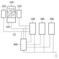
도 4는 본 발명의 일 실시예에 따른 자가 구동 외력 감지 센서의 회로도이다.
도 5는 본 발명의 일 실시예에 따른 외력이 전도성 스펀지에 작용하는 과정을 설명하기 위한 도면이다.
도 6은 본 발명의 일 실시예에 따른 제1 전극의 배치를 설명하기 위한 도면이다.1 and 2 are views for explaining a conductive sponge according to an embodiment of the present invention.
3 is a block diagram of a low-cost driving external force detection sensor according to an embodiment of the present invention.
4 is a circuit diagram of a self-driving external force detection sensor according to an embodiment of the present invention.
5 is a view for explaining a process in which an external force acts on a conductive sponge according to an embodiment of the present invention.
6 is a diagram for explaining the arrangement of the first electrode according to an embodiment of the present invention.
본 명세서에 개시되어 있는 본 발명의 개념에 따른 실시예들에 대해서 특정한 구조적 또는 기능적 설명들은 단지 본 발명의 개념에 따른 실시예들을 설명하기 위한 목적으로 예시된 것으로서, 본 발명의 개념에 따른 실시예들은 다양한 형태로 실시될 수 있으며 본 명세서에 설명된 실시예들에 한정되지 않는다.Specific structural or functional descriptions of the embodiments according to the concept of the present invention disclosed in this specification are only illustrated for the purpose of explaining the embodiments according to the concept of the present invention, and the embodiments according to the concept of the present invention These may be embodied in various forms and are not limited to the embodiments described herein.
본 발명의 개념에 따른 실시예들은 다양한 변경들을 가할 수 있고 여러 가지 형태들을 가질 수 있으므로 실시예들을 도면에 예시하고 본 명세서에 상세하게 설명하고자 한다. 그러나, 이는 본 발명의 개념에 따른 실시예들을 특정한 개시형태들에 대해 한정하려는 것이 아니며, 본 발명의 사상 및 기술 범위에 포함되는 변경, 균등물, 또는 대체물을 포함한다.Embodiments according to the concept of the present invention can apply various changes and can have various forms, so the embodiments are illustrated in the drawings and described in detail herein. However, this is not intended to limit the embodiments according to the concept of the present invention to specific disclosures, and includes modifications, equivalents, or substitutes included in the spirit and scope of the present invention.
제1 또는 제2 등의 용어를 다양한 구성요소들을 설명하는데 사용될 수 있지만, 상기 구성요소들은 상기 용어들에 의해 한정되어서는 안 된다. 상기 용어들은 하나의 구성요소를 다른 구성요소로부터 구별하는 목적으로만, 예를 들어 본 발명의 개념에 따른 권리 범위로부터 이탈되지 않은 채, 제1 구성요소는 제2 구성요소로 명명될 수 있고, 유사하게 제2 구성요소는 제1 구성요소로도 명명될 수 있다.Terms such as first or second may be used to describe various components, but the components should not be limited by the terms. The above terms are used only for the purpose of distinguishing one component from another component, for example, without departing from the scope of rights according to the concept of the present invention, a first component may be named a second component, Similarly, the second component may also be referred to as the first component.
어떤 구성요소가 다른 구성요소에 "연결되어" 있다거나 "접속되어" 있다고 언급된 때에는, 그 다른 구성요소에 직접적으로 연결되어 있거나 또는 접속되어 있을 수도 있지만, 중간에 다른 구성요소가 존재할 수도 있다고 이해되어야 할 것이다. 반면에, 어떤 구성요소가 다른 구성요소에 "직접 연결되어" 있다거나 "직접 접속되어" 있다고 언급된 때에는, 중간에 다른 구성요소가 존재하지 않는 것으로 이해되어야 할 것이다. 구성요소들 간의 관계를 설명하는 표현들, 예를 들어 "~사이에"와 "바로~사이에" 또는 "~에 직접 이웃하는" 등도 마찬가지로 해석되어야 한다.It is understood that when an element is referred to as being "connected" or "connected" to another element, it may be directly connected or connected to the other element, but other elements may exist in the middle. It should be. On the other hand, when an element is referred to as “directly connected” or “directly connected” to another element, it should be understood that no other element exists in the middle. Expressions describing the relationship between components, such as "between" and "directly between" or "directly adjacent to" should be interpreted similarly.
본 명세서에서 사용한 용어는 단지 특정한 실시예들을 설명하기 위해 사용된 것으로, 본 발명을 한정하려는 의도가 아니다. 단수의 표현은 문맥상 명백하게 다르게 뜻하지 않는 한, 복수의 표현을 포함한다. 본 명세서에서, "포함하다" 또는 "가지다" 등의 용어는 설시된 특징, 숫자, 단계, 동작, 구성요소, 부분품 또는 이들을 조합한 것이 존재함으로 지정하려는 것이지, 하나 또는 그 이상의 다른 특징들이나 숫자, 단계, 동작, 구성요소, 부분품 또는 이들을 조합한 것들의 존재 또는 부가 가능성을 미리 배제하지 않는 것으로 이해되어야 한다.Terms used in this specification are only used to describe specific embodiments, and are not intended to limit the present invention. Singular expressions include plural expressions unless the context clearly dictates otherwise. In this specification, terms such as "comprise" or "have" are intended to designate that the described feature, number, step, operation, component, part, or combination thereof exists, but one or more other features or numbers, It should be understood that the presence or addition of steps, operations, components, parts, or combinations thereof is not precluded.
다르게 정의되지 않는 한, 기술적이거나 과학적인 용어를 포함해서 여기서 사용되는 모든 용어들은 본 발명이 속하는 기술 분야에서 통상의 지식을 가진 자에 의해 일반적으로 이해되는 것과 동일한 의미를 가진다. 일반적으로 사용되는 사전에 정의되어 있는 것과 같은 용어들은 관련 기술의 문맥상 가지는 의미와 일치하는 의미를 갖는 것으로 해석되어야 하며, 본 명세서에서 명백하게 정의하지 않는 한, 이상적이거나 과도하게 형식적인 의미로 해석되지 않는다.Unless defined otherwise, all terms used herein, including technical or scientific terms, have the same meaning as commonly understood by one of ordinary skill in the art to which the present invention belongs. Terms such as those defined in commonly used dictionaries should be interpreted as having a meaning consistent with the meaning in the context of the related art, and unless explicitly defined in this specification, it should not be interpreted in an ideal or excessively formal meaning. don't
이하, 실시예들을 첨부된 도면을 참조하여 상세하게 설명한다. 그러나, 특허출원의 범위가 이러한 실시예들에 의해 제한되거나 한정되는 것은 아니다. 각 도면에 제시된 동일한 참조 부호는 동일한 부재를 나타낸다.Hereinafter, embodiments will be described in detail with reference to the accompanying drawings. However, the scope of the patent application is not limited or limited by these examples. Like reference numerals in each figure indicate like elements.
도 1 및 도 2는 본 발명의 일 실시예에 따른 다공성 구조의 전도성 스펀지를 설명하기 위한 도면이다.1 and 2 are views for explaining a conductive sponge having a porous structure according to an embodiment of the present invention.
도 1을 참조하면, 본 발명의 일 실시예에 따른 다공성 구조의 전도성 스펀지는 실리콘 물질, 금속성 물질 및 설탕 입자를 혼합하고, 혼합물을 주형 틀에 넣어 사용하고자 하는 형상을 갖도록 굳히며, 굳은 혼합물을 온수를 이용하여 용해시키면 설탕 입자가 용해됨에 따라 공극(air gap)이 형성됨으로써 얻어질 수 있다.Referring to FIG. 1, a conductive sponge having a porous structure according to an embodiment of the present invention mixes a silicon material, a metallic material, and sugar particles, puts the mixture into a mold and hardens it to have a shape to be used, and forms the hardened mixture. When dissolved using hot water, it can be obtained by forming an air gap as the sugar particles are dissolved.
실리콘 물질은 다공성 구조의 전도성 스펀지의 탄성(복원력)에 기여할 수 있다.The silicone material can contribute to the elasticity (resilience) of the porous structure conductive sponge.
금속성 물질은 스펀지의 내부에 산재되어 있으며, 스펀지의 형상 변화에 따라 상호 마찰되어 전기 에너지를 생성하는데 기여할 수 있다.Metallic materials are interspersed inside the sponge, and may contribute to generating electrical energy by rubbing against each other according to the shape change of the sponge.
본 발명에 대한 실험예에서는 시판되는 Ecoflex?? 00-30을 실리콘 물질로 사용하였으며, 갈륨, 인듐 및 주석 등으로 구성되며 시판되는 갈린스탄(Galinstan)을 금속성 물질로 사용하였다.In the experimental example for the present invention, commercially available Ecoflex?? 00-30 was used as a silicon material, and commercially available Galinstan, which is composed of gallium, indium and tin, was used as a metallic material.
이하, 본 명세서에서 언급되는 다공성 구조의 전도성 스펀지는 외력에 의해 형상이 변화하고 탄성에 의해 다시 원 형상으로 되돌아 가는 과정에서 내부 금속성 물질의 마찰에 의해 전기 에너지를 발생시키는 스펀지를 일체를 의미할 수 있다. 따라서,, 본 발명의 이해를 돕기 위한 일 예시로서 도 1과 관련하여 언급된 예에 한정되는 것은 아니다.Hereinafter, the porous conductive sponge referred to in this specification may refer to a sponge that generates electric energy by friction of an internal metallic material in the process of changing its shape by external force and returning to its original shape by elasticity. there is. Therefore, it is not limited to the example mentioned in relation to FIG. 1 as an example to help understanding of the present invention.
이때, 발생하는 전기 에너지는 다공성 구조의 전도성 스펀지에 가해지는 외력에 비례할 수 있다.At this time, the generated electrical energy may be proportional to the external force applied to the conductive sponge having a porous structure.
도 2를 참조하면, 본 발명의 일 실시예에 따른 다공성 구조의 전도성 스펀지의 전력 발생 원리가 도시되어 있다.Referring to FIG. 2 , a principle of power generation of a porous conductive sponge according to an embodiment of the present invention is illustrated.
도 2 (A)에서, 다공성 구조의 전도성 스펀지의 일 공극 영역이 도시되어 있으며, 이러한 일 공극 영역은 스펀지 구조를 형성하는 실리콘 물질과 실리콘 물질에 부분적으로 산재된 금속성 물질을 포함할 수 있다.In FIG. 2(A), one void region of the conductive sponge having a porous structure is shown, and this one void region may include a silicon material forming the sponge structure and a metallic material partially interspersed in the silicon material.
도 2 (B)와 같이, 다공성 구조의 전도성 스펀지에 외력이 가해지면 다공성 구조의 전도성 스펀지가 수축 또는 변형됨에 따라 금속성 물질들 간의 마찰에 의한 정전기가 발생할 수 있다.As shown in FIG. 2 (B), when an external force is applied to the porous conductive sponge, the porous conductive sponge shrinks or deforms, and static electricity may be generated due to friction between metallic materials.
도 2 (C)와 같이, 다공성 구조의 전도성 스펀지에 가해지던 외력이 사라지면, 다공성 구조의 전도성 스펀지가 탄력에 의해 원래 형상으로 돌아가는 과정에서 금속성 물질들 간의 마찰에 의한 정전기가 발생할 수 있다.As shown in FIG. 2 (C), when the external force applied to the porous conductive sponge disappears, static electricity may be generated due to friction between metallic materials while the porous conductive sponge returns to its original shape due to elasticity.
이때, 도 2 (B)와 같이 외력에 의해 다공성 구조의 전도성 스펀지가 수축되는 과정에서 발생하는 전류 또는 전압의 방향과 도 2 (C)와 같이 다공성 구조의 전도성 스펀지에 가해지던 외력이 사라짐에 따라 원래 형상으로 돌아 가는 과정에서 발생하는 전류 또는 전압의 방향은 상반될 수 있다.At this time, as shown in FIG. 2 (B), the direction of the current or voltage generated in the process of shrinking the porous structure conductive sponge by the external force and the external force applied to the porous structure conductive sponge as shown in FIG. 2 (C) disappear. The direction of the current or voltage generated in the process of returning to the original shape may be reversed.
또한, 이러한 다공성 구조의 전도성 스펀지를 이용하여 전력을 발생하는 기술은 이미 해당 기술분야에 널리 알려져 있으므로 이에 대한 상세한 설명은 생략한다.In addition, since a technology for generating power using such a porous conductive sponge is already well known in the art, a detailed description thereof will be omitted.
도 3은 본 발명의 일 실시예에 따른 자가 구동 외력 감지 센서의 블록도이다.3 is a block diagram of a self-driving external force detection sensor according to an embodiment of the present invention.
도 3을 참조하면, 자가 구동 외력 감지 센서(3000)는 전도성 스펀지(3100), 전극부(3200), 전류-전압 모니터링부(3300), 외력 분석부(3400), 출력부(350) 및 전원부(3600)를 포함할 수 있다.Referring to FIG. 3 , the self-driving external
전도성 스펀지(3100)는 외력에 의해 수축 등 변형되는 과정에서 마찰 전기를 발생시키고, 외력에 의해 변형된 형상이 다시 원 형상으로 돌아 가는 과정에 마찰 전기를 발생시키는 다공성 구조의 전도성 스펀지를 의미할 수 있다. 따라서, 도 1 및 도 2에 설명된 다공성 구조의 전도성 스펀지에 반드시 한정되는 것은 아니다.The
일 실시예에서, 외력은 사람, 기구, 바람 등에 의해 직접적으로 가해지는 힘, 모터 등과 같이 특정 동작을 수행하는 기계 장치에 의해 발생하는 진동 등을 의미할 수 있다. 따라서, 본 발명에 따른 자가 구동 외력 감지 센서는 단순히 외력의 세기, 방향 등 뿐만 아니라, 모터 등의 기계에 의해 발생되는 진동까지 분석할 수 있음은 자명하다.In one embodiment, the external force may mean force directly applied by a person, instrument, wind, or the like, vibration generated by a mechanical device that performs a specific operation, such as a motor, or the like. Therefore, it is obvious that the self-driving external force detection sensor according to the present invention can analyze not only the intensity and direction of external force, but also vibration generated by a machine such as a motor.
전극부(3200)는 전도성 스펀지(3100)와 전기적 접촉이 없는 이격된 상태를 유지하다가 전도성 스펀지(3100)에 외력이 가해져 전도성 스펀지(3100)가 변형됨에 따라 적어도 하나가 전도성 스펀지(3100)의 일 영역과 접촉하는 복수의 제1 전극(3210)과, 전도성 스펀지(3100)의 타 영역과 항시 전기적으로 접촉된 상태를 유지하는 제2 전극(3220)을 포함할 수 있다.The
일 실시예에서, 복수의 제1 전극(3210)은 전도성 스펀지(3100) 주변에 서로 이격되어 배치될 수 있다. 이때, 복수의 제1 전극(3210)이 배치 정보는 미리 설정될 수 있다.In one embodiment, the plurality of
일 실시예에서, 복수의 제1 전극(3210)의 배치 정보는 외력의 방향을 판단하는데 이용되므로 제1 전극(3210)의 개수 및 배치는 사용 목적에 따라 결정될 수 있다. 예를 들어, 복수의 제1 전극(3210)은 2 개의 제1 전극(3210) 각각이 전도성 스펀지(3100)를 중심으로 좌측 및 우측 각각에 배치되거나 4개의 제1 전극(3210)이 전도성 스펀지(3100)를 중심으로 4방에 배치될 수 있다.In an embodiment, since information about the arrangement of the plurality of
일 실시예에서, 제1 전극(3210) 및 제2 전극(3220)은 금(Au), 은(Ag), 백금(Pt), 철(Fe), 구리(Cu) 등의 전도성 금속일 수 있다.In one embodiment, the
전류-전압 모니터링부(3300)는 외력에 의해 전도성 스펀지(3100)에 발생하는 전류 또는 전압을 모니터링할 수 있다. 구체적으로, 전류-전압 모니터링부(3300)는 복수의 제1 전극(3210) 및 제2 전극(3220)과 전기적으로 연결되며, 복수의 제1 전극(3210) 및 제2 전극(3220) 사이에 발생하는 전류 또는 전압을 측정함으로써 외력에 의해 전도성 스펀지(3100)에 의해 발생하는 전류 또는 전압을 모니터링할 수 있다.The current-
일 실시예에서, 전류-전압 모니터링부(3300)는 복수의 제1 전극과 제2 전극 사이에 발생하는 전류를 측정하기 위한 전류계를 포함할 수 있다.In one embodiment, the current-
일 실시예에서, 전류-전압 모니터링부(3300)는 복수의 제1 전극과 제2 전극 사이에 발생하는 전압을 측정하기 위한 전압계를 포함할 수 있다.In one embodiment, the current-
일 실시예에서, 전류-전압 모니터링부(3300)는 전도성 스펀지(3100)에 외력이 가해진 경우, 복수의 제1 전극(3210) 중 어느 전극과 제2 전극(3220) 사이에 전류 또는 전압이 발생하는지를 모니터링할 수 있다. 구체적으로, 전류-전압 모니터링부(3300)는 전도성 스펀지(3100)의 우측에 배치된 제1 전극(3210) 방향으로 외력이 작용하여 전도성 스펀지(3100)가 우측에 배치된 제1 전극(3210)과 접촉하게 되면, 복수의 제1 전극(3210) 중 전도성 스펀지(3100)의 우측에 배치된 제1 전극(3210)과 제2 전극(3220) 사이에 전류 또는 전압이 발생하고, 복수의 제1 전극(3210) 중 전도성 스펀지(3100)의 우측에 배치된 제1 전극(3210)을 제외한 나머지 제1 전극(3210)과 제2 전극(3220) 사이에는 전류 또는 전압이 발생하지 않음을 모니터링할 수 있다.In one embodiment, the current-
일 실시예에서, 전류-전압 모니터링부(3300)는 복수의 제1 전극(3210)과 제2 전극(3220) 사이에 발생하는 전류의 방향 또는 전압의 극성 변화를 모니터링할 수 있다. 전도성 스펀지(3100)에 외력이 작용하여 전도성 스펀지(3100)의 형상이 변경되는 과정에서 복수의 제1 전극(3210)과 제2 전극 사이에 발생하는 전류의 방향 또는 전압의 극성은, 더 이상 전도성 스펀지(3100)에 외력이 작용하지 않아 전도성 스펀지(3100)의 자체 탄성(또는 복원력)에 의해서 전도성 스펀지(3100)의 원형상으로 돌아가는 과정에서 복수의 제1 전극(3210)과 제2 전극 사이에 발생하는 전류의 방향 또는 전압의 극성이 상반될 수 있다. 따라서, 본 발명에 따른 자가 구동 외력 감지 센서(3000)는 복수의 제1 전극(3210)과 제2 전극(3220) 사이에 발생하는 전류의 방향 또는 전압의 극성을 모니터링함으로써 외력이 작용하는(유지되는) 시간을 판단할 수 있다.In an embodiment, the current-
일 실시예에서, 전류-전압 모니터링부(3300)는 제1 전극(3210)과 제2 전극(3220) 사이에 발생하는 전류 또는 전압의 크기를 모니터링할 수 있다. 전도성 스펀지(3100)에 의해 발생하는 전류 또는 전압은 전도성 스펀지(3100)에 작용하는 외력의 크기에 상응하여 복수의 제1 전극(3210)과 제2 전극(3220) 사이에 발생하는 전류 또는 전압의 크기가 증가할 수 있다. 따라서, 본 발명에 다른 자가 구동 외력 감지 센서(3000)는 복수의 제1 전극(3210)과 제2 전극(3220) 사이에 발생하는 전류 또는 전압의 크기를 기반으로 외력의 세기를 판단할 수 있다.In one embodiment, the current-
일 실시예에서, 전류-전압 모니터링부(3300)는 제1 전극(3210)과 제2 전극(3220) 사이에 발생하는 전류 또는 전압의 지속시간을 모니터링할 수 있다. 외력 분석부(3400)는 전도성 스펀지(3100)에 가해지는 외력을 분석할 수 있다. 구체적으로, 외력 분석부(3400)는 복수의 제1 전극(3210) 및 제2 전극(3220) 사이에 발생하는 전류 또는 전압을 모니터링한 결과를 기반으로, 전도성 스펀지(3100)에 가해지는 외력의 방향, 세기, 지속 시간 등을 분석할 수 있다.In one embodiment, the current-
일 실시예에서, 외력 분석부(3400)는 외력의 방향을 분석할 수 있다. 구체적으로, 외력 분석부(3400)는 복수의 제1 전극(3210) 중 제2 전극(3220)과 사이에서 전류 또는 전압이 발생한 제1 전극(3210)의 배치 정보를 기반으로 전도성 스펀지(3100)에 가해지는 외력의 방향을 분석할 수 있다. 예를 들어, 복수의 제1 전극(3210)이 각각 전도성 스펀지(3100)의 좌측 및 우측에 각각 배열된 경우, 전도성 스펀지(3100)에 외력이 작용하여 우측에 배열된 제1 전극(3210)과 제2 전극(3220) 사이에 전류 또는 전압이 발생하면, 외력 분석부(3400)는 전도성 스펀지(3100)에 좌측에서 우측 방향으로 외력이 작용한 것으로 판단할 수 있다.In one embodiment, the
일 실시예에서, 외력 분석부(3400)는 외력의 지속 시간을 분석할 수 있다. 구체적으로, 외력 분석부(3400)는 전도성 스펀지(3100)가 외력에 의해 형상이 변형되는 과정에 제1 전극(3210)과 제2 전극(3220) 사이에 전류 또는 전압이 발생하기 시작한 시간(t1)과 전도성 스펀지(3100)가 탄성에 의해 원 형상으로 돌아가는 과정에 의해 제1 전극(3210)과 제2 전극(3220) 사이에 다시 전류 또는 전압이 발생하는 시간(t2)을 기반으로 외력이 작용한 시간을 분석할 수 있다. 이 경우, 외력이 지속된 시간은 t2- t1가 된다.In one embodiment, the
일 실시예에서, 외력 분석부(3400)는 외력의 세기를 분석할 수 있다. 구체적으로, 외력에 의해 전도성 스펀지(3100)에 발생하는 전압 또는 전류의 크기는 외력의 세기에 비례하거나 외력의 세기의 증가시에 함께 증가하는 경향으로 가지므로, 외력 분석부(3400)는 제1 전극(3210)과 제2 전극(3220) 사이에 발생하는 전류 또는 전압의 세기를 기반으로 전도성 스펀지(3100)에 가해지는 외력의 세기를 분석할 수 있다.In one embodiment, the
출력부(350)는 외력의 방향, 세기, 지속 시간 등을 포함하는 외력 분석 결과를 출력할 수 있다.The output unit 350 may output an external force analysis result including the direction, intensity, and duration of the external force.
일 실시예에서, 출력부(350)는 외력 분석 결과를 유무선 통신 수단을 이용하여 외부 기기로 전송할 수 있으며, 이를 위해 유무선 통신 모듈(미도시)을 포함할 수 있다.In one embodiment, the output unit 350 may transmit the external force analysis result to an external device using a wired/wireless communication means, and may include a wired/wireless communication module (not shown) for this purpose.
일 실시예에서, 출력부(350)는 외력 분석 결과를 사람이 시각, 청각 등을 통해 인식할 수 있도록 출력할 수 있으며, 이를 위해 오디오 모듈(미도시), 디스플레이 모듈(미도시) 등을 포함할 수 있다.In one embodiment, the output unit 350 may output the external force analysis result so that a person can recognize it through sight, hearing, etc., and for this purpose, an audio module (not shown), a display module (not shown), and the like are included. can do.
전원부(3600)는 복수의 제1 전극(3210) 및 제2 전극(3220)에 연결되어, 전도성 스펀지(3100)에 작용하여 외력에 의해 발생하는 전력을 저장할 수 있다. 전원부(3600)는 저장된 전력을 기반으로 자가 구동 외력 감지 센서(3000)가 동작하기 위한 전력을 공급할 수 있다.The
일 실시예에서, 전원부(3600)는 커패시터 또는 인덕터와 같이 전력의 저장 및 방전이 가능한 소자일 수 있다.In one embodiment, the
일 실시예에서, 전원부(3600)는 전력을 충전 및 방전하는 납 축전지(Lead_Acid), 니켈 카드뮴(Ni-Cd) 전지, 니켈 수소(Ni-MH) 전지, 리튬 이온(Li-ion) 전지, 리튬 폴리머(Li-Polymer) 전지 등의 2차 전지를 포함할 수 있다.In one embodiment, the
도 4는 본 발명의 일 실시예에 따른 자가 구동 외력 감지 센서의 회로도이다.4 is a circuit diagram of a self-driving external force detection sensor according to an embodiment of the present invention.
도 4를 참조하면, 복수의 제1 전극(3210) 각각은 전도성 스펀지(3100)의 좌측 및 우측에 전도성 스펀지(3100)와 이격되어 배치되며, 제2 전극(3220)은 전도성 스펀지(3100)의 하면에 접촉하여 배치된다. 전도성 스펀지(3100)에 우측 방향으로 외력이 작용하는 경우 우측에 배치된 제1 전극(3210)과 제2 전극(3220) 사이에 전류 또는 전압이 발생하고, 전도성 스펀지(3100)에 좌측 방향으로 외력이 작용하는 경우 좌측에 배치된 제1 전극(3210)과 제2 전극(3220) 사이에 전류 또는 전압이 발생할 수 있다.Referring to FIG. 4 , each of the plurality of
전류-전압 모니터링부(3300)는 복수의 제1 전극(3210) 및 제2 전극(3220)과 전기적으로 연결되어, 복수의 제1 전극(3210) 중 적어도 하나와 제2 전극(3220) 사이에 발생하는 전류 또는 전압의 크기, 방향, 지속 시간 등의 모니터링할 수 있다. 전류-전압 모니터링부(3300)는 외력 분석부(3400)와 연결된 데이터 라인을 통해 전류-전압 모니터링 결과를 외력 분석부(3400)에 전달할 수 있다.The current-
외력 분석부(3400)는 전류-전압 모니터링부(3300)와 연결된 데이터 라인(미도시)을 통해 전류-전압 모니터링 결과를 전류-전압 모니터링부(3300)로부터 수신할 수 있다. 외력 부석부는 전류-전압 모니터링 결과를 기반으로 외력의 방향, 세기, 지속 시간 등을 포함하는 외력 분석 결과를 생성할 수 있다. 외력 분석부(3400)는 출력부(350)와 연결된 데이터 라인(미도시)을 통해 외력 분석 결과를 출력부(350)에 전달할 수 있다.The
출력부(350)는 외력 분석부(3400)와 연결된 데이터 라인을 통해 외력 분석 결과를 외력 분석부(3400)로부터 수신할 수 있다. 출력부(350)는 외력 분석 결과를 유무선 통신 수단을 이용하여 외부 장치로 전송하거나 사용자가 인식할 수 있도록 출력할 수 있다.The output unit 350 may receive an external force analysis result from the
전력부는 전류-전압 모니터링부(3300), 외력 분석부(3400) 및 출력부(350) 각각에 연결되며, 이들을 구동하기 위한 전력을 공급할 수 있다. 전력부는 복수의 제1 전극(3210) 및 제2 전극(3220)에 연결되며, 스펀지에 가해지는 외력에 의해 발생하는 전력을 저장할 수 있다.The power unit is connected to each of the current-
도 5는 본 발명의 일 실시예에 따른 외력이 전도성 스펀지에 작용하는 과정을 설명하기 위한 도면이다.5 is a view for explaining a process in which an external force acts on a conductive sponge according to an embodiment of the present invention.
도 5를 참조하면, 도 5 (A) 및 도 5 (B) 각각은 외력이 가해지기 전의 자가 구동 외력 감지 장치의 상면 및 측면을 나타내고, 도 5 (C) 및 도 5 (D) 각각은 외력이 가해지는 과정의 자가 구동 외력 감지 장치의 상면 및 측면을 나타낸다.Referring to FIG. 5 , FIGS. 5 (A) and 5 (B) each show a top and side view of the self-driving external force sensing device before an external force is applied, and FIGS. 5 (C) and 5 (D) each show an external force The top and side views of the self-driving external force sensing device in the process of being applied are shown.
도 5 (A) 및 도 5 (B)에서, 복수의 제1 전극(3210)은 전도성 스펀지(3100)의 좌우측에 각각 이격되어 배치되어 있다. 따라서, 전도성 스펀지(3100)에 외력이 작용하기 전에는 전도성 스펀지(3100)와 제1 전극(3210) 사이가 이격되어 있다. 또한, 도시되지 않았으나 제2 전극(3220)은 전도성 스펀지(3100)의 하면에 접촉되어 배치된 것으로 가정한다.5(A) and 5(B) , the plurality of
도 5 (C) 및 (D)에서, 전도성 스펀지(3100)에 우측 방향으로 외력이 작용하면 전도성 스펀지(3100)는 우측 방향으로 밀리는 형태로 변형되어 우측에 배치된 제1 전극(3210)과 접촉하게 된다. 이때, 전도성 스펀지(3100)는 우측에 배치된 제1 전극(3210)과 제2 전극(3220) 사이에 전류 또는 전압을 발생시키게 된다.5(C) and (D), when an external force is applied to the
또한, 외력이 전도성 스펀지(3100)에 집중될 수 있도록 전도성 스펀지(3100)의 상부는 아치형으로 형성될 수 있다.Also, an upper portion of the
또한, 제1 전극(3210) 및 제2 전극(3220)의 높이는 전도성 스펀지(3100)와 대비하여 상대적으로 낮게 설정될 수 있다.Also, the heights of the
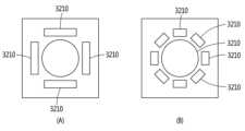
도 6은 본 발명의 일 실시예에 따른 제1 전극의 배치를 설명하기 위한 도면이다.6 is a diagram for explaining the arrangement of the first electrode according to an embodiment of the present invention.
도 6을 참조하면, 도 6 (A)는 전도성 스펀지(3100)를 중심으로 4방 각각에 배치된 4개의 제1 전극(3210)의 예가 도시되고, 도 6 (B)는 전도성 스펀지(3100)를 중심으로 8방 각각에 배치된 8개의 제1 전극(3210)의 예가 도시되어 있다.Referring to FIG. 6, FIG. 6 (A) shows an example of four
도 6 (A)에서, 전도성 스펀지(3100)를 중심으로 4방 각각에 제1 전극(3210)이 배치되어 있으므로, 자가 구동 외력 감지 센서(3000)는 4방 중 어느 하나에 작용하는 외력의 방향, 세기, 지속 시간 등을 분석할 있다. 또한, 자가 구동 외력 감지 센서(3000)는 4방 중 어느 하나에 배치된 제1 전극(3210)과 이와 인접하여 배치된 제1 전극(3210) 각각과 제2 전극(3220) 사이에 전류 또는 전압이 발생하는 경우, 상기 두 개의 제1 전극(3210)이 배치된 중간 지점 방향으로 외력이 작용한 것으로 분석할 수 있다.6(A), since the
도 6 (B)에서, 전도성 스펀지(3100)를 중심으로 8방 각각에 제1 전극(3210)이 배치되어 있으므로, 자가 구동 외력 감지 센서(3000)는 8방 중 어느 하나에 작용하는 외력의 방향, 세기, 지속 시간 등을 분석할 있다. 또한, 자가 구동 외력 감지 센서(3000)는 8방 중 어느 하나에 배치된 제1 전극(3210)과 이와 인접하여 배치된 제1 전극(3210) 각각과 제2 전극(3220) 사이에 전류 또는 전압이 발생하는 경우, 상기 두 개의 제1 전극(3210)이 배치된 중간 지점 방향으로 외력이 작용한 것으로 분석할 수 있다.6(B), since the
따라서, 도 6 (A) 및 도 6 (B)를 통해 확인할 수 있는 바와 같이, 전도성 스펀지(3100) 주변에 배치되는 제1 전극(3110)의 개수를 늘릴수록, 자가 구동 외력 감지 센서(3000)가 측정할 수 있는 외력의 작용 방향이 증가함을 확인할 수 있다. 즉, 본 명세서에서 예시된 제1 전극(3110)의 개수는 본 발명의 이해를 돕기 위한 예시적인 것에 불과하므로, 자가 구동 외력 감지 센서(3000)가 사용되는 목적에 따라 제1 전극(3110)의 개수 및 배치를 상이하게 할 수 있음은 통상의 기술자에게 자명하다.Therefore, as can be seen through FIGS. 6(A) and 6(B) , as the number of first electrodes 3110 disposed around the
이상에서 설명된 장치는 하드웨어 구성요소, 소프트웨어 구성요소, 및/또는 하드웨어 구성요소 및 소프트웨어 구성요소의 조합으로 구현될 수 있다. 예를 들어, 실시예들에서 설명된 장치 및 구성요소는, 예를 들어, 프로세서, 콘트롤러, ALU(arithmetic logic unit), 디지털 신호 프로세서(digital signal processor), 마이크로컴퓨터, FPGA(field programmable gate array), PLU(programmable logic unit), 마이크로프로세서, 또는 명령(instruction)을 실행하고 응답할 수 있는 다른 어떠한 장치와 같이, 하나 이상의 범용 컴퓨터 또는 특수 목적 컴퓨터를 이용하여 구현될 수 있다. 처리 장치는 운영 체제(OS) 및 운영 체제 상에서 수행되는 하나 이상의 소프트웨어 애플리케이션을 수행할 수 있다. 또한, 처리 장치는 소프트웨어의 실행에 응답하여, 데이터를 접근, 저장, 조작, 처리 및 생성할 수도 있다. 이해의 편의를 위하여, 처리 장치는 하나가 사용되는 것으로 설명된 경우도 있지만, 해당 기술분야에서 통상의 지식을 가진 자는, 처리 장치가 복수 개의 처리 요소(processing element) 및/또는 복수 유형의 처리 요소를 포함할 수 있음을 알 수 있다. 예를 들어, 처리 장치는 복수 개의 프로세서 또는 하나의 프로세서 및 하나의 콘트롤러를 포함할 수 있다. 또한, 병렬 프로세서(parallel processor)와 같은, 다른 처리 구성(processing configuration)도 가능하다.The devices described above may be implemented as hardware components, software components, and/or a combination of hardware components and software components. For example, devices and components described in the embodiments may include, for example, a processor, a controller, an arithmetic logic unit (ALU), a digital signal processor, a microcomputer, a field programmable gate array (FPGA) , a programmable logic unit (PLU), microprocessor, or any other device capable of executing and responding to instructions. The processing device may run an operating system (OS) and one or more software applications running on the operating system. A processing device may also access, store, manipulate, process, and generate data in response to execution of software. For convenience of understanding, there are cases in which one processing device is used, but those skilled in the art will understand that the processing device includes a plurality of processing elements and/or a plurality of types of processing elements. It can be seen that it can include. For example, a processing device may include a plurality of processors or a processor and a controller. Other processing configurations are also possible, such as parallel processors.
이상과 같이 실시예들이 비록 한정된 도면에 의해 설명되었으나, 해당 기술분야에서 통상의 지식을 가진 자라면 상기의 기재로부터 다양한 수정 및 변형이 가능하다. 예를 들어, 설명된 기술들이 설명된 방법과 다른 순서로 수행되거나, 및/또는 설명된 시스템, 구조, 장치, 회로 등의 구성요소들이 설명된 방법과 다른 형태로 결합 또는 조합되거나, 다른 구성요소 또는 균등물에 의하여 대치되거나 치환되더라도 적절한 결과가 달성될 수 있다.As described above, although the embodiments have been described with limited drawings, those skilled in the art can make various modifications and variations from the above description. For example, the described techniques may be performed in an order different from the method described, and/or components of the described system, structure, device, circuit, etc. may be combined or combined in a different form than the method described, or other components may be used. Or even if it is replaced or substituted by equivalents, appropriate results can be achieved.
그러므로, 다른 구현들, 다른 실시예들 및 특허청구범위와 균등한 것들도 후술하는 특허청구범위의 범위에 속한다.Therefore, other implementations, other embodiments, and equivalents of the claims are within the scope of the following claims.
3000: 자가 구동 외력 감지 센서3100: 전도성 스펀지
3200: 전극부3300: 전류-전압 모니터링부
3400: 외력 분석부3500: 출력부
3600: 전원부3000: self-driving external force detection sensor 3100: conductive sponge
3200: electrode unit 3300: current-voltage monitoring unit
3400: external force analysis unit 3500: output unit
3600: power supply
Claims (11)
Translated fromKorean상기 외력이 상기 전도성 스펀지에 작용하기 전에는 상기 전도성 스펀지와 모두 이격 되고 상기 외력에 상기 전도성 스펀지에 작용하면 적어도 하나가 상기 전도성 스펀지와 접촉하도록, 서로 상이한 위치에 배열되는 복수의 제1 전극;
상기 복수의 제1 전극의 전압 및 전류 중 적어도 하나를 모니터링하는 전류-전압 모니티링부; 및
상기 복수의 제1 전극의 전압 변화 및 전류 변화 중 적어도 하나와, 상기 제1 전극의 배열 정보를 기반으로, 상기 전도성 스펀지에 작용하는 상기 외력의 방향을 판단하는 외력 분석부;
를 포함하고,
상기 전도성 스펀지에 의해 생산된 전기 에너지를 저장하고, 상기 전류-전압 모니터링부 및 상기 외력 분석부의 구동 전력을 공급하는 전원부를 더 포함하는, 자가 구동 외력 감지 센서.
A conductive sponge with a porous structure that produces electrical energy by changing its shape due to external force;
A plurality of first electrodes arranged at different positions from each other such that all of them are spaced apart from the conductive sponge before the external force acts on the conductive sponge and at least one contacts the conductive sponge when the external force acts on the conductive sponge;
a current-voltage monitoring unit monitoring at least one of voltage and current of the plurality of first electrodes; and
an external force analyzer configured to determine a direction of the external force acting on the conductive sponge based on at least one of a voltage change and a current change of the plurality of first electrodes and arrangement information of the first electrodes;
including,
A self-driving external force detection sensor further comprising a power supply unit for storing electric energy produced by the conductive sponge and supplying driving power to the current-voltage monitoring unit and the external force analysis unit.
상기 외력 분석부는,
상기 복수의 제1 전극 중 전압 또는 전류 중 적어도 하나의 변화가 발생한 적어도 하나의 제1 전극이 배열된 위치 방향으로, 상기 외력이 작용하는 것으로 판단하는, 자가 구동 외력 감지 센서.
According to claim 1,
The external force analysis unit,
A self-driving external force detection sensor that determines that the external force acts in a direction where at least one first electrode of the plurality of first electrodes where a change in at least one of voltage or current occurs is arranged.
상기 외력 분석부는,
상기 복수의 제1 전극의 전압 변화 크기 또는 전류 변화 크기를 기반으로, 상기 전도성 스펀지에 작용하는 상기 외력의 세기를 더 판단하는, 자가 구동 외력 감지 센서.
According to claim 1,
The external force analysis unit,
A self-driving external force sensor that further determines the intensity of the external force acting on the conductive sponge based on the magnitude of voltage change or current change of the plurality of first electrodes.
상기 전도성 스펀지는, 상기 외력의 세기에 상응하여 증가하는 전기 에너지를 생성하는, 자가 구동 외력 감지 센서.
According to claim 1,
The conductive sponge generates electrical energy that increases in correspondence with the intensity of the external force, the self-driving external force detection sensor.
상기 외력 분석부는,
상기 복수의 제1 전극의 전압 극성 변화 또는 전류의 방향 변화를 기반으로, 상기 외력의 지속 시간을 더 판단하는, 자가 구동 외력 감지 센서.
According to claim 1,
The external force analysis unit,
The self-driving external force detection sensor further determines a duration of the external force based on a change in voltage polarity or a change in direction of current of the plurality of first electrodes.
상기 전도성 스펀지는,
상기 외력에 의한 형상 변화가 있은 후 더 이상 외력이 작용하지 않으면, 다시 원 형상으로 돌아가는 탄성을 갖는, 자가 구동 외력 감지 센서.
According to claim 1,
The conductive sponge,
A self-driving external force detection sensor having elasticity that returns to the original shape when the external force no longer acts after the shape change due to the external force.
상기 복수의 제1 전극 중 적어도 하나의 전압의 극성 또는 전류의 방향은,
상기 전도성 스펀지가 상기 외력에 의해 형상에 변화가 일어나는 시간 동안과 상기 탄성에 의해 다시 원 형상으로 돌아 가는 시간 동안 서로 상반되는, 자가 구동 외력 감지 센서.
According to claim 6,
The polarity of the voltage or the direction of the current of at least one of the plurality of first electrodes,
The self-driving external force sensor, which is opposite to each other during the time when the shape of the conductive sponge is changed by the external force and the time when the shape is returned to the original shape by the elasticity.
판단된 외력의 방향을 포함하는 외력 분석 결과를 출력하는 출력부를 더 포함하는, 자가 구동 외력 감지 센서.
According to claim 1,
A self-driving external force detection sensor further comprising an output unit outputting an external force analysis result including a direction of the determined external force.
상기 출력부는,
상기 외력 분석 결과를 외부 기기로 전송하는 유선 또는 무선 통신 모듈인, 자가 구동 외력 감지 센서.
According to claim 9,
the output unit,
A self-driving external force detection sensor that is a wired or wireless communication module that transmits the external force analysis result to an external device.
상기 출력부는, 상기 외력 분석 결과를 시각적으로 출력하는 디스플레이인, 자가 구동 외력 감지 센서.
According to claim 9,
The output unit is a display that visually outputs the external force analysis result, a self-driving external force sensor.
Priority Applications (1)
| Application Number | Priority Date | Filing Date | Title |
|---|---|---|---|
| KR1020210078778AKR102541817B1 (en) | 2021-06-17 | 2021-06-17 | External force sensor with self-powered |
Applications Claiming Priority (1)
| Application Number | Priority Date | Filing Date | Title |
|---|---|---|---|
| KR1020210078778AKR102541817B1 (en) | 2021-06-17 | 2021-06-17 | External force sensor with self-powered |
Publications (2)
| Publication Number | Publication Date |
|---|---|
| KR20220168818A KR20220168818A (en) | 2022-12-26 |
| KR102541817B1true KR102541817B1 (en) | 2023-06-12 |
Family
ID=84547701
Family Applications (1)
| Application Number | Title | Priority Date | Filing Date |
|---|---|---|---|
| KR1020210078778AActiveKR102541817B1 (en) | 2021-06-17 | 2021-06-17 | External force sensor with self-powered |
Country Status (1)
| Country | Link |
|---|---|
| KR (1) | KR102541817B1 (en) |
Citations (3)
| Publication number | Priority date | Publication date | Assignee | Title |
|---|---|---|---|---|
| JP2003242849A (en) | 2002-02-14 | 2003-08-29 | Fujitsu Component Ltd | Pressing direction detection sensor and input device using the same |
| KR102139819B1 (en) | 2019-04-24 | 2020-07-30 | (주)일렉콤 | self-generating device using piezoelectric elementbn |
| JP2021067542A (en)* | 2019-10-23 | 2021-04-30 | 株式会社Kri | pressure sensor |
Family Cites Families (1)
| Publication number | Priority date | Publication date | Assignee | Title |
|---|---|---|---|---|
| KR101973011B1 (en) | 2017-11-17 | 2019-04-26 | 한국생산기술연구원 | Triboelectric energy harvester having conductive sponge |
- 2021
- 2021-06-17KRKR1020210078778Apatent/KR102541817B1/enactiveActive
Patent Citations (3)
| Publication number | Priority date | Publication date | Assignee | Title |
|---|---|---|---|---|
| JP2003242849A (en) | 2002-02-14 | 2003-08-29 | Fujitsu Component Ltd | Pressing direction detection sensor and input device using the same |
| KR102139819B1 (en) | 2019-04-24 | 2020-07-30 | (주)일렉콤 | self-generating device using piezoelectric elementbn |
| JP2021067542A (en)* | 2019-10-23 | 2021-04-30 | 株式会社Kri | pressure sensor |
Also Published As
| Publication number | Publication date |
|---|---|
| KR20220168818A (en) | 2022-12-26 |
Similar Documents
| Publication | Publication Date | Title |
|---|---|---|
| JP6250809B2 (en) | Battery pack having a spring for connecting to at least two battery cells | |
| US11334164B2 (en) | Portable electronic device having a haptic device with a moving battery element | |
| JP2016526866A (en) | Single-electrode friction nano-generator, power generation method, and self-driven tracking device | |
| TWI596825B (en) | Constrained anode fiber for rechargeable battery | |
| WO2016060694A1 (en) | Battery management system and method | |
| CN106159356B (en) | A kind of battery and electronic equipment | |
| US20230296676A1 (en) | System for assessment of battery cell dimensional variation | |
| CN104733796A (en) | Touch Sensor Element For Detecting Critical Situations In Battery Cell | |
| JP2020506498A5 (en) | ||
| Wang et al. | A passive DC current sensing methodology | |
| CN110542767A (en) | A kind of high-sensitivity self-powered acceleration sensor and preparation method thereof | |
| KR102541817B1 (en) | External force sensor with self-powered | |
| KR102026170B1 (en) | electrical energy harvester capable of measuring deformation and tactile force | |
| CN114754859B (en) | Self-driven mechanical vibration sensor and mechanical vibration monitoring method | |
| CN111313741A (en) | A stretchable power generation device | |
| KR20230018169A (en) | Triboelectric energy harvester using wind power | |
| KR20180137308A (en) | Battery module | |
| CN111829647A (en) | A pendulum type three-dimensional vibration acceleration sensor | |
| JP2012252934A (en) | Battery, power generator, battery drive system, and method for detecting expansion of battery | |
| KR20220111587A (en) | Battery inspection apparatus and battery inspection method | |
| CN107525554B (en) | Flow sensor | |
| KR920004497Y1 (en) | Multi axes type vibration measuring apparatus using piezoelectric devices | |
| Xu et al. | A Hybridized Metal/Polydimethylsiloxane Sponge for Multidirectional Pressure Energy Harvesting | |
| CN221652408U (en) | Motor monitoring device | |
| CN110849509A (en) | Self-powered stress detection device, detection method and application |
Legal Events
| Date | Code | Title | Description |
|---|---|---|---|
| PA0109 | Patent application | Patent event code:PA01091R01D Comment text:Patent Application Patent event date:20210617 | |
| PA0201 | Request for examination | ||
| PG1501 | Laying open of application | ||
| E902 | Notification of reason for refusal | ||
| PE0902 | Notice of grounds for rejection | Comment text:Notification of reason for refusal Patent event date:20230118 Patent event code:PE09021S01D | |
| E701 | Decision to grant or registration of patent right | ||
| PE0701 | Decision of registration | Patent event code:PE07011S01D Comment text:Decision to Grant Registration Patent event date:20230602 | |
| GRNT | Written decision to grant | ||
| PR0701 | Registration of establishment | Comment text:Registration of Establishment Patent event date:20230605 Patent event code:PR07011E01D | |
| PR1002 | Payment of registration fee | Payment date:20230607 End annual number:3 Start annual number:1 | |
| PG1601 | Publication of registration |