KR102541728B1 - Multi-pivot hinge - Google Patents
Multi-pivot hingeDownload PDFInfo
- Publication number
- KR102541728B1 KR102541728B1KR1020177017523AKR20177017523AKR102541728B1KR 102541728 B1KR102541728 B1KR 102541728B1KR 1020177017523 AKR1020177017523 AKR 1020177017523AKR 20177017523 AKR20177017523 AKR 20177017523AKR 102541728 B1KR102541728 B1KR 102541728B1
- Authority
- KR
- South Korea
- Prior art keywords
- individual
- computing device
- rotation
- hinge assembly
- sequential multi
- Prior art date
- Legal status (The legal status is an assumption and is not a legal conclusion. Google has not performed a legal analysis and makes no representation as to the accuracy of the status listed.)
- Active
Links
Images


Classifications
- G—PHYSICS
- G06—COMPUTING OR CALCULATING; COUNTING
- G06F—ELECTRIC DIGITAL DATA PROCESSING
- G06F1/00—Details not covered by groups G06F3/00 - G06F13/00 and G06F21/00
- G06F1/16—Constructional details or arrangements
- G06F1/1613—Constructional details or arrangements for portable computers
- G06F1/1633—Constructional details or arrangements of portable computers not specific to the type of enclosures covered by groups G06F1/1615 - G06F1/1626
- G06F1/1675—Miscellaneous details related to the relative movement between the different enclosures or enclosure parts
- G06F1/1681—Details related solely to hinges
- E—FIXED CONSTRUCTIONS
- E05—LOCKS; KEYS; WINDOW OR DOOR FITTINGS; SAFES
- E05D—HINGES OR SUSPENSION DEVICES FOR DOORS, WINDOWS OR WINGS
- E05D11/00—Additional features or accessories of hinges
- E05D11/0054—Covers, e.g. for protection
- E—FIXED CONSTRUCTIONS
- E05—LOCKS; KEYS; WINDOW OR DOOR FITTINGS; SAFES
- E05D—HINGES OR SUSPENSION DEVICES FOR DOORS, WINDOWS OR WINGS
- E05D11/00—Additional features or accessories of hinges
- E05D11/0081—Additional features or accessories of hinges for transmitting energy, e.g. electrical cable routing
- E—FIXED CONSTRUCTIONS
- E05—LOCKS; KEYS; WINDOW OR DOOR FITTINGS; SAFES
- E05D—HINGES OR SUSPENSION DEVICES FOR DOORS, WINDOWS OR WINGS
- E05D11/00—Additional features or accessories of hinges
- E05D11/06—Devices for limiting the opening movement of hinges
- E—FIXED CONSTRUCTIONS
- E05—LOCKS; KEYS; WINDOW OR DOOR FITTINGS; SAFES
- E05D—HINGES OR SUSPENSION DEVICES FOR DOORS, WINDOWS OR WINGS
- E05D11/00—Additional features or accessories of hinges
- E05D11/10—Devices for preventing movement between relatively-movable hinge parts
- E05D11/1014—Devices for preventing movement between relatively-movable hinge parts for maintaining the hinge in only one position, e.g. closed
- E—FIXED CONSTRUCTIONS
- E05—LOCKS; KEYS; WINDOW OR DOOR FITTINGS; SAFES
- E05D—HINGES OR SUSPENSION DEVICES FOR DOORS, WINDOWS OR WINGS
- E05D3/00—Hinges with pins
- E05D3/06—Hinges with pins with two or more pins
- E—FIXED CONSTRUCTIONS
- E05—LOCKS; KEYS; WINDOW OR DOOR FITTINGS; SAFES
- E05D—HINGES OR SUSPENSION DEVICES FOR DOORS, WINDOWS OR WINGS
- E05D7/00—Hinges or pivots of special construction
- E05D7/12—Hinges or pivots of special construction to allow easy detachment of the hinge from the wing or the frame
- G—PHYSICS
- G06—COMPUTING OR CALCULATING; COUNTING
- G06F—ELECTRIC DIGITAL DATA PROCESSING
- G06F1/00—Details not covered by groups G06F3/00 - G06F13/00 and G06F21/00
- G06F1/16—Constructional details or arrangements
- G06F1/1613—Constructional details or arrangements for portable computers
- G06F1/1615—Constructional details or arrangements for portable computers with several enclosures having relative motions, each enclosure supporting at least one I/O or computing function
- G06F1/1616—Constructional details or arrangements for portable computers with several enclosures having relative motions, each enclosure supporting at least one I/O or computing function with folding flat displays, e.g. laptop computers or notebooks having a clamshell configuration, with body parts pivoting to an open position around an axis parallel to the plane they define in closed position
- H—ELECTRICITY
- H04—ELECTRIC COMMUNICATION TECHNIQUE
- H04M—TELEPHONIC COMMUNICATION
- H04M1/00—Substation equipment, e.g. for use by subscribers
- H04M1/02—Constructional features of telephone sets
- H04M1/0202—Portable telephone sets, e.g. cordless phones, mobile phones or bar type handsets
- H04M1/0206—Portable telephones comprising a plurality of mechanically joined movable body parts, e.g. hinged housings
- H04M1/0208—Portable telephones comprising a plurality of mechanically joined movable body parts, e.g. hinged housings characterized by the relative motions of the body parts
- H04M1/0214—Foldable telephones, i.e. with body parts pivoting to an open position around an axis parallel to the plane they define in closed position
- H04M1/0216—Foldable in one direction, i.e. using a one degree of freedom hinge
- H04M1/022—The hinge comprising two parallel pivoting axes
- E—FIXED CONSTRUCTIONS
- E05—LOCKS; KEYS; WINDOW OR DOOR FITTINGS; SAFES
- E05D—HINGES OR SUSPENSION DEVICES FOR DOORS, WINDOWS OR WINGS
- E05D7/00—Hinges or pivots of special construction
- E05D7/12—Hinges or pivots of special construction to allow easy detachment of the hinge from the wing or the frame
- E05D2007/128—Hinges or pivots of special construction to allow easy detachment of the hinge from the wing or the frame in a radial direction
- E—FIXED CONSTRUCTIONS
- E05—LOCKS; KEYS; WINDOW OR DOOR FITTINGS; SAFES
- E05Y—INDEXING SCHEME ASSOCIATED WITH SUBCLASSES E05D AND E05F, RELATING TO CONSTRUCTION ELEMENTS, ELECTRIC CONTROL, POWER SUPPLY, POWER SIGNAL OR TRANSMISSION, USER INTERFACES, MOUNTING OR COUPLING, DETAILS, ACCESSORIES, AUXILIARY OPERATIONS NOT OTHERWISE PROVIDED FOR, APPLICATION THEREOF
- E05Y2999/00—Subject-matter not otherwise provided for in this subclass
Landscapes
- Engineering & Computer Science (AREA)
- Computer Hardware Design (AREA)
- Theoretical Computer Science (AREA)
- Physics & Mathematics (AREA)
- Mechanical Engineering (AREA)
- Human Computer Interaction (AREA)
- General Engineering & Computer Science (AREA)
- General Physics & Mathematics (AREA)
- Signal Processing (AREA)
- Mathematical Physics (AREA)
- Pivots And Pivotal Connections (AREA)
- Hinges (AREA)
Abstract
Translated fromKorean
Description
Translated fromKoreanUS2013135890호는 힌지 디바이스 및 이러한 힌지 디바이스를 구비하는 접철식 장치(folded apparatus)를 개시한다. 힌지 디바이스는 힌지 브라켓, 서로 평행하게 제공되며 힌지 브라켓에 의해 회전 가능하게 지지되는 제1 축 및 제2 축을 포함한다. 제1 축은 장치의 제1 본체(body)에 연결되고, 제2 축은 장치의 제2 본체에 연결된다. 제1 본체는, 제1 축 및 제2 축을 통해 제2 본체에 대해 0도에서부터 360도까지 및/또는 360도에서부터 0도까지 회전할 수 있다.
EP276478호는, 제1 및 제2 디바이스 유닛 및 제2 디바이스 유닛을 제1 디바이스 유닛에 선회 가능하게(pivotably) 연결하도록 구성되는 적어도 하나의 힌지 어셈블리를 포함하는 휴대형 전자 디바이스를 개시하는데, 힌지 어셈블리는 제1 디바이스 유닛에 고정되도록 구성되는 제1 고정 유닛, 제2 디바이스 유닛에 고정되도록 구성되는 제2 고정 유닛 및 서로 평행하게 배열되도록 구성되는 복수의 샤프트 부재를 포함한다.
첨부의 도면은 본 문서에서 전달되는 개념의 구현예를 예시한다. 예시된 구현예의 특징은 첨부의 도면과 연계하여 취해지는 하기의 설명을 참조로 더 쉽게 이해될 수 있다. 동일한 엘리먼트를 나타내기에 적합한 곳마다, 다양한 도면에서 동일한 도면 부호가 사용된다. 또한, 각각의 도면 부호의 가장 왼쪽의 숫자는, 그 도면 부호가 처음으로 도입되는 도면 및 관련 논의를 시사한다.
도 1 내지 도 4는 본 발명의 몇몇 구현예에 따른 순차적 멀티 피벗 힌지 어셈블리 예를 포함하는 예시적인 디바이스의 사시도를 도시한다.
도 5 내지 도 6은 사시도이고, 도 7은 본 개념의 몇몇 구현예에 따른 순차적 멀티 피벗 힌지 어셈블리 예의 분해 사시도이다.
도 8은 도 7에서 도입되는 개개의 힌지 스택 예의 분해 사시도이다.
도 8a는 도 8의 개개의 링크의 사시도이다.
도 9 및 도 10은 본 개념의 몇몇 구현예에 따른 순차적 멀티 피벗 힌지 어셈블리 예의 입면도이다.US2013135890 discloses a hinge device and a folded apparatus having such a hinge device. The hinge device includes a hinge bracket, a first shaft and a second shaft provided parallel to each other and rotatably supported by the hinge bracket. The first shaft is connected to the first body of the device and the second shaft is connected to the second body of the device. The first body can rotate from 0 degrees to 360 degrees and/or from 360 degrees to 0 degrees with respect to the second body through the first axis and the second axis.
EP276478 discloses a portable electronic device comprising first and second device units and at least one hinge assembly configured to pivotably connect the second device unit to the first device unit, the hinge assembly comprising: It includes a first fixing unit configured to be fixed to the first device unit, a second fixing unit configured to be fixed to the second device unit, and a plurality of shaft members configured to be arranged parallel to each other.
The accompanying drawings illustrate implementations of the concepts conveyed herein. Features of the illustrated implementations may be more readily understood with reference to the following description taken in conjunction with the accompanying drawings. Like reference numerals are used in the various drawings wherever appropriate to refer to like elements. Also, the leftmost digit of each reference number indicates the drawing and related discussion in which the reference number was first introduced.
1-4 show perspective views of exemplary devices that include examples of sequential multi-pivot hinge assemblies in accordance with some implementations of the present invention.
5-6 are perspective views, and FIG. 7 is an exploded perspective view of an example sequential multi-pivot hinge assembly in accordance with some implementations of the present concepts.
8 is an exploded perspective view of an individual hinge stack example introduced in FIG. 7;
Figure 8a is a perspective view of the individual links of Figure 8;
9 and 10 are elevation views of an example sequential multi-pivot hinge assembly in accordance with some implementations of the present concepts.
본 개념은 컴퓨팅 디바이스의 일부를 회전 가능하게 고정하기 위해 멀티 피벗 또는 다축(multi-axis) 힌지 어셈블리를 활용하는 컴퓨팅 디바이스에 관한 것이다. 본 발명의 힌지는, 개개의 힌지가 회전하는 상대적인 순서를 멀티 피벗 힌지 어셈블리가 제어할 수 있다는 점에서, 순차적 힌지(sequential hinge)로서 생각될 수 있다. 하나의 이러한 구성은 힌지가 처음부터 끝까지 미리 정의된 순서대로(예를 들면, 순차적으로) 동작하게 할 수 있다. 그러한 만큼, 멀티 피벗 힌지 어셈블리는 '순차적 멀티 피벗 힌지 어셈블리'로 칭해질 수 있다.The concept relates to a computing device that utilizes a multi-pivot or multi-axis hinge assembly to rotatably secure a portion of the computing device. The hinge of the present invention can be thought of as a sequential hinge in that the multi-pivot hinge assembly can control the relative order in which the individual hinges rotate. One such configuration may cause the hinges to operate in a predefined order (eg sequentially) from start to finish. To that extent, the multi-pivot hinge assembly can be referred to as a 'sequential multi-pivot hinge assembly'.
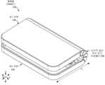
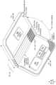
입문적인(introductory) 도 1 내지 도 3은 컴퓨팅 디바이스(100)의 예를 총괄하여 도시한다. 이 예에서, 컴퓨팅 디바이스(100)는 순차적 멀티 피벗 힌지 어셈블리(106)에 의해 함께 회전 가능하게 고정되는 제1 및 제2 부분(102 및 104)을 구비한다. 도 1 및 도 2는 '닫힌' 위치에 있는 컴퓨팅 디바이스를 도시한다. 도 1은 컴퓨팅 디바이스(100)를 '전방(front)'에서부터 도시하고, 도 2는 컴퓨팅 디바이스를 '후방(back)'에서부터 도시한다. 도 3은, '열린' 또는 '전개된' 위치에 있는 컴퓨팅 디바이스를 도시하는 부분 절개 사시도이다. 이 예에서, 전개된 위치에서, 제1 및 제2 부분은, 도 1 및 2의 닫힌 위치에서의 제로에 가까운 각도와는 대조적으로, 서로에 대해 둔각(α)을 정의할 수 있다. 다른 구현예에서, 전개된 위치는 90도 이하 또는 180도 이상일 수 있다(예를 들면, 책과 같은 구성). 예를 들면, 전개된 위치는, 유저에게 편안한 시야각인 90도 내지 180도의 범위 안의 어느 곳일 수 있다.The introductory FIGS. 1-3 collectively illustrate an
도 3으로부터 알 수 있는 바와 같이, 순차적 멀티 피벗 힌지 어셈블리(106)는 다수의 힌지 스택(302)을 포함할 수 있다. 순차적 멀티 피벗 힌지 어셈블리(106)의 양태는 도 5 내지 도 10과 관련하여 이하에서 보다 상세하게 설명된다. 이 예에서, 순차적 멀티 피벗 힌지 어셈블리는, 힌지 스택(302)을 비롯한 기저의 엘리먼트(underlying element)를 덮어 감출 수 있는 및/또는 보호할 수 있는 강성의(rigid) 관절식으로 이어진(articulating) 힌지 커버(304)를 포함한다. 다른 구현예는 강성의 관절식으로 이어진 커버를 포함하지 않는다. 또 다른 구현예는, 순차적 멀티 피벗 힌지 어셈블리(106)에 걸쳐 제1 부분(102)과 제2 부분(104) 사이에서 연장하는 가요성 힌지 커버를 포함할 수 있다.As can be seen from FIG. 3 , sequential multi-pivot hinge assembly 106 can include
도 3에서 입증되는 바와 같이, 컴퓨팅 디바이스(100)는 또한 입력 엘리먼트 또는 디바이스(308)를 포함할 수 있다. 이 경우, 입력 디바이스(308)는 키보드(310)로서 나타난다. 다른 구현예는 다른 입력 디바이스를 활용할 수 있다. 이 예에서, 컴퓨팅 디바이스는 또한 터치 감지형 디스플레이 스크린과 같은 디스플레이 스크린(312)을 포함할 수 있다. 컴퓨팅 디바이스는 또한, 다른 컴포넌트/엘리먼트 중에서도, 프로세서(314), 메모리/스토리지(316), 배터리(318), 및/또는 비디오 또는 그래픽 프로세서(320)를 포함할 수 있다. 이들 엘리먼트는 제1 부분(102) 및/또는 제2 부분(104)에 배치될 수 있다.As demonstrated in FIG. 3 ,
이 경우, 제2 부분(104)은 테이블 상부와 같은 일반적으로 수평인 표면(특별히 지정되지는 않음) 상에 배치되도록 구성될 수 있다. 도 1 및 도 2의 닫힌 위치에서, 제1 및 제2 부분은 일반적으로 서로에 대해 그리고 수평면에 평행하다(예를 들면, 제1 부분은 제2 부분 위에 병치된다(juxtapose)). 대조적으로, 도 3의 전개된 위치에서, 제1 부분은 제2 부분으로부터, 이 경우에서는 둔각으로 회전된다.In this case, the
도 1 및 도 2의 닫힌 위치에서, 순차적 멀티 피벗 힌지 어셈블리(106)는 작고 운반하기 쉬운 풋프린트(footprint)(fc)를 제공할 수 있다는 것에 유의한다. 이 구현예에서, 순차적 멀티 피벗 힌지 어셈블리(106)의 점진적인 또는 순차적 성질(nature)은, 디바이스가 도 1 및 도 2의 닫힌 또는 보관 위치(storage position)로부터 도 3의 열린 또는 전개된 위치로 전환될 때 컴퓨팅 디바이스의 풋프린트를 증가 또는 확장시킬 수 있다는 것에 또한 유의한다. 예를 들면, 닫힌 풋프린트(fc)를 전개된 또는 확장된 풋프린트(fd)와 비교한다. 이 확장된 풋프린트 특징은, 디스플레이(312), 프로세서(314), 메모리/스토리지(316), 및 배터리(318)와 같은 전자 컴포넌트 중 일부 또는 전부가 제1 부분(102)에 배치되는 이 구현에서 특히 중요할 수 있다. 순차적 멀티 피벗 힌지 어셈블리에 의해 제공되는 확장된 풋프린트는 컴퓨팅 디바이스의 안정성을 증가시킬 수 있고, 이들 컴포넌트의 중량으로부터 전개된 위치에서 디바이스가 후방으로 뒤집힐(tip over) 가능성을 감소시킬 수 있다. 환언하면, 순차적 멀티 피벗 힌지 어셈블리의 순차적 성질은, 컴퓨팅 디바이스(100)를 안정화시키고 뒤집힘을 감소시키는(예를 들면, 풋프린트 위에 질량의 중심을 유지하는) 것을 도울 수 있는 전개된 위치에서의 풋(foot)(322)을 생성할 수 있다.Note that in the closed position of FIGS. 1 and 2 , the sequential multi-pivot hinge assembly 106 can provide a small, easy-to-carry footprint fc . In this implementation, the gradual or sequential nature of the sequential multi-pivot hinge assembly 106 allows the device to transition from the closed or storage position of FIGS. 1 and 2 to the open or deployed position of FIG. 3 . It is also noted that the footprint of the computing device may be increased or expanded when it is available. For example, a closed footprint (fc ) is compared to an expanded or expanded footprint (fd ). This extended footprint feature is such that some or all of the electronic components such as display 312, processor 314, memory/
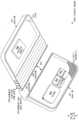
도 3에서 도시되는 구현예에서, 순차적 멀티 피벗 힌지 어셈블리(106)는, 비교적 영구적인 방식으로(예를 들면, 최종 사용 소비자에 의해 쉽게 분리될 수 있도록 의도되지 않는 방식으로) 제1 및 제2 부분(102 및 104)에 고정될 수 있다. 대안적으로, 순차적 멀티 피벗 힌지 어셈블리(106)는 비교적 신속하게 부착가능한/분리가능한 방식으로(예를 들면 최종 사용 소비자에 의해 쉽게 분리될 수 있도록 의도되는 방식으로) 제1 및 제2 부분(102, 104)에 고정될 수 있다. 이 후자 구성의 하나의 이러한 예가 도 4에 도시되어 있다.In the implementation shown in FIG. 3 , the sequential multi-pivot hinge assembly 106 connects the first and second in a relatively permanent manner (eg, in a manner not intended to be readily detachable by the end-use consumer). It can be fixed to
도 4는 도 3의 뷰와 유사한 뷰에서 다른 컴퓨팅 디바이스(100A)를 도시한다. 이 예에서, 순차적 멀티 피벗 힌지 어셈블리(106A)는 최종 사용 소비자가 화살표(402)에 의해 나타내어지는 바와 같이 순차적 멀티 피벗 힌지 어셈블리(106A)로부터 제1 및 제2 부분(102 및 104) 중 어느 하나 또는 둘 모두를 쉽게 분리하는 것을 허용하도록 구성된다. 이 예에서, 순차적 멀티 피벗 힌지 어셈블리(106)는 신속한 부착/분리 어셈블리(404)를 포함할 수 있다. 신속한 부착/분리 어셈블리(404)는 제1 부분(102) 및 순차적 멀티 피벗 힌지 어셈블리(106A) 상에 각각 배치되는 협력적으로 동작하는 엘리먼트(406, 408)를 포함할 수도 있다.FIG. 4 shows another computing device 100A in a view similar to that of FIG. 3 . In this example, the sequential multi-pivot hinge assembly 106A is configured so that the end-use consumer can select one of the first and
하나의 예에서, 엘리먼트(406)는 래치로서 나타날 수 있고 엘리먼트(408)는 수신기로서 나타날 수 있다. 래치는 수신기와 결합하여 제1 부분(102)을 순차적 멀티 피벗 힌지 어셈블리(106A)와 분리 가능하게 커플링할 수 있다. 다른 예에서, 엘리먼트(406 및 408)는, 순차적 멀티 피벗 힌지 어셈블리(106A)로부터 제1 부분을 분리하기 위해 유저에 의해 극복될 수 있는 방식으로 서로 자기적으로 커플링될 수 있다. 다른 신속한 부착/분리 어셈블리(404)가 고려된다. 순차적 멀티 피벗 힌지 어셈블리(106A)는 제1 및/또는 제2 부분 중 어느 하나 또는 둘 모두와 분리 가능하게 연결될 수도 있다. 기계적 커플링에 대안적으로 또는 부가적으로, 신속한 부착/분리 어셈블리(404)는 제1 및 제2 부분의 전자 컴포넌트를 분리 가능하게 전기적으로 커플링할 수 있다. 예를 들면, 신속한 부착/분리 어셈블리(404)는, 프로세서(314), 스토리지/메모리(316), 및/또는 배터리(318)를, 제1 부분(102)으로부터, 제2 부분(104)의 그래픽 프로세서(320) 및/또는 키보드(310)로 전기적으로 커플링할 수도 있다.In one example,
따라서, 신속한 부착/분리 어셈블리(404)는, 유저가 제1 부분(102) 또는 제2 부분(104)을 분리하여 어느 한 부분을 다른 부분과는 독립적으로 사용할 수 있게 할 수 있다. 예를 들면, 제1 부분(102)은 독립형 태블릿 디바이스로서 동작될 수 있고, 순차적 멀티 피벗 힌지 어셈블리(106A)를 통해 제2 부분(104)에 부착되어 랩탑 디바이스와 더욱 유사한 디바이스를 형성할 수도 있다. 유저는 또한 애플리케이션 고유의 디바이스에 대해 제1 부분(102) 또는 제2 부분(104)을 교환할 수 있을 수도 있다. 예를 들면, 개개의 제2 부분은 키보드 및/또는 터치스크린을 포함할 수도 있다. 특정 시나리오에서, 유저는 제1 부분으로서 제1 터치스크린을 부착할 수도 있고 제2 부분으로서 제2 터치스크린을 부착할 수 있으며, 책과 같은 디바이스를 활용할 수도 있다. 다른 시나리오에서, 유저는 제1 부분으로서 터치스크린을 그리고 제2 부분으로서, 키보드 및 트랙 패드로서 나타나는 입력 디바이스를 부착할 수도 있고, 랩톱과 같은 디바이스를 활용할 수도 있다. 다른 구성 및 구현예가 고려된다.Thus, the quick attach/detach assembly 404 allows a user to detach either the
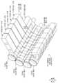
도 5 내지 도 10은, 도 3과 관련하여 상기에서 소개되는 힌지 스택(302)을 포함하는 예시적인 순차적 멀티 피벗 힌지 어셈블리(106)에 관한 더 세부적인 사항을 총괄하여 예시한다. 도면 페이지 상의 공간적 제약으로 인해, 모든 요소가 각각의 도면에서 라벨링되는 것은 아니며 모든 엘리먼트의 모든 인스턴스가 라벨링되는 것은 아니고, 오히려 대표적인 엘리먼트가 라벨링된다. 도 5는 도 1과 유사한 닫힌 또는 보관 위치에 있는 순차적 멀티 피벗 힌지 어셈블리(106)를 도시한다. 도 6은 도 3과 유사한 열린 또는 전개된 위치에 있는 순차적 멀티 피벗 힌지 어셈블리(106)를 도시한다. 도 7은 도 6의 뷰와 유사한 분해도를 도시한다. 도 8은 개개의 힌지 스택(302(5))의 분해도이다.5-10 collectively illustrate further details regarding an exemplary sequential multi-pivot hinge assembly 106 including
도 5 내지 도 8을 참조하면, 예시적인 순차적 멀티 피벗 힌지 어셈블리(106)는 회전 제한기(rotation limiter; 502), 키형 샤프트(keyed shaft; 504), 시퀀스화 핀(sequencing pin; 506)(도 7)을 포함할 수 있다. 개개의 힌지 스택(302)은 제1 부분 엘리먼트(510), 다수의 방사상으로 배열된 링크(512), 및 제2 부분 엘리먼트(514)를 포함할 수 있다. 키형 샤프트(504)는 힌지 스택(302) 및 회전 제한기(502)를 통과한다. 키형 샤프트(504)는 링크(512)가 회전(또는 피벗)하는 회전축을 정의한다. 시퀀스화 핀은, 링크(512)를 통해 형성되는 채널(516)(도 7)에 존재하는 일종의 로킹 캠 부재(locking cam member)로서 생각될 수 있다. 다양한 유형의 회전 제한기(502)가 활용될 수 있다. 도 6과 관련하여 도시되는 바와 같이, 개개의 회전 제한기는 개개의 회전축 주위의 회전의 각도(b)(도 6)를 정의할 수 있다.5-8, an exemplary sequential multi-pivot hinge assembly 106 includes a
도 8은 부분적으로 분해된 개개의 힌지 스택(302(5))을 도시한다. 이 경우, 링크(512(5)A)는 제2 부분 엘리먼트(514)(5)에 대해 배치된다. 이 도면에서, 링크(512(5)A)로부터 제2 부분 엘리먼트를 구별함에 있어서 독자를 돕기 위해, 제2 부분 엘리먼트(514(5))는 크로스 해칭으로 도시되어 있다. 개개의 링크(512)는 중심 영역(806)에 의해 제2 영역(804)에 연결되는 제1 영역(802)을 갖는 오프셋 구성을 갖는다. 도 8은 다수의 구조체 및 지정자(designator)를 포함한다. 명확화를 위해, 도 8a는 개개의 제1 영역(802), 제2 영역(804) 및 중앙 영역(806)을 원으로 둘러싼 개개의 링크(512(5))를 분리하여 도시한다. 하나의 관점에서, 개개의 링크의 오프셋 성질은 (예를 들면, xz 기준 평면(reference plane)을 따라 볼 때) 번개 표시(lighting bolt) 형상의 일부를 근사하는 것으로 특성화될 수 있다.8 shows an individual hinge stack 302(5) partially exploded. In this case, link 512(5)A is positioned relative to second partial element 514(5). In this figure, to assist the reader in distinguishing the second portion element from link 512(5)A, second portion element 514(5) is shown with cross hatching. Each
도 8 및 도 8a를 참조하면, 제1 영역(802)은 제1 통로(808)를 정의할 수 있다. 마찬가지로, 제2 영역(804)은 제1 영역에 평행한 제2 통로(810)를 정의할 수 있다. 링크(512(5)B)와 같은 개개의 링크의 제1 영역(802)은, 링크(512(5)A)와 같은 인접한 링크의 제2 영역(804)과 정렬되어, 개개의 키형 샤프트(504), 예컨대 화살표(812)에 의해 나타내어지는 바와 같은 키형 샤프트(504(2))를 받을 수도 있다.Referring to FIGS. 8 and 8A , a
링크의 중심 영역(806)은 키형 샤프트(504)에 의해 정의되는 힌지 축에 일반적으로 평행하게 연장할 수 있다. 이로써, 중앙 영역(806)은, 제1 및 제2 영역(802, 804)이 평행하게 정의하나 통로(808 및 810)를 오프셋시킬 수 있는 것인 링크(512(5))의 오프셋 구성을 지지하기 위해 키형 샤프트(504)에 일반적으로 평행하게 연장할 수 있다. 따라서, 이 예에서, 상기에서 언급되는 바와 같이, 링크(512(5)B)의 제1 영역(802)은 화살표(812)에 의해 나타내어지는 바와 같이 키형 샤프트(504(2))를 받도록 링크(512(5)A)의 제2 영역에 대해 배치될 수 있다. 링크(512(5)A)의 제1 영역(802)은 차례로 제2 부분 엘리먼트(514(5))와 정렬될 수 있다. 제2 부분 엘리먼트는 종단(terminus)(814)을 포함할 수 있다. 종단은 통로(816)를 정의할 수 있다. 화살표(818)에 의해 나타내어지는 바와 같이 제2 부분 엘리먼트(514(5))를 링크(512(5)A)에 회전 가능하게 결합하기 위해, 키형 샤프트(504(1))는 링크(822(2)A)의 통로(816) 및 통로(808)(링크(822(2)A)의 통로(808)는 보이지는 않지만, 통로는 링크(512(5)B)와 관련하여 지정된다)를 통과할 수 있다. 마찬가지로, 키형 샤프트(504(3))는 화살표(820)에 의해 나타내어지는 바와 같이 링크(512(5)B)의 제2 영역(804)을 링크(512(5)C)의 제1 영역(802)에 회전 가능하게 결합할 수 있다.The
이 구현예에서, 키형 샤프트(504)는 그들의 장축을 가로 질러 봤을 때(예를 들면, xz 기준 평면을 따라 봤을 때) 원형 프로파일을 갖지 않는다. 대신, 이 경우, 키형 샤프트는 대문자 "D"에 근사하는 프로파일을 갖는다. 제2 통로(810)는, 키형 샤프트가 제2 영역(804)에 대해 적합되도록(keyed) 또는 로킹되도록 유사한 프로파일을 갖는다. 대조적으로, 제1 통로(808)는 원형 프로파일을 갖는다. 이 구성은, '전방' 링크가 키형 샤프트 주위로 회전하는 것을 방지하면서 '후방' 링크가 키형 샤프트를 중심으로 회전하는 것을 허용할 수 있다. 따라서, 키형 샤프트가 제1 링크에 대해 회전 불가능하게 하고 제2 링크에 대해 회전 가능하게 하는 다른 키형 샤프트 프로파일이 활용될 수 있다는 것이 고려된다. 예를 들면, 전방 링크의 통로가 별(star) 프로파일과 일치하고 후방 링크가 별의 외측 점에 의해 정의되는 직경을 갖는 원형인 별 형상의 프로파일이 활용될 수 있을 것이다.In this embodiment, the
링크(512(5)B)와 같은 개개의 링크(512)는 다수의 캠 표면(822)을 정의할 수 있다. 이 예에서, 링크는 4 개의 지정된 캠 표면(822)을 정의할 수 있다. 중앙 영역(806)에 근접한 제1 영역(802)에 제1 개개의 캠 표면(822(1))이 형성될 수 있다. 중앙 영역으로부터 떨어진 제1 영역(802)에 제2 개개의 캠 표면(822(2))이 형성될 수 있다. 마찬가지로, 중앙 영역(806)에 근접한 제2 영역(804)에 제3 개개의 캠 표면(822(3))이 형성될 수 있고, 중앙 영역으로부터 떨어진 제1 영역(802)에 제4 개개의 캠 표면(822(4))이 형성될 수 있다. 개개의 링크(512(5))의 캠 표면(822(1) 및 822(3))은 채널(516)을 부분적으로 정의할 수 있고, 따라서 개개의 시퀀스화 핀(506)에 대해 (예를 들면, 도 8과 관련하여 x 기준 방향에서) 전후 방향의 병진 자유도(fore-aft translational degree of freedom)를 규정할 수 있다. 따라서, 몇몇 경우에서, 하기에서 더 상세히 설명되는 바와 같이, 캠 표면(822(1) 및 822(3))이 채널(516)(도 7)을 간단히 정의하지만, 개개의 링크에 의한 회전을 제어함에 있어서 표면(822(2) 및 822(4))이 수반된다. 또한 모든 캠 표면이 특별히 논의되고 지정되는 것은 아니다는 것에 유의한다. 예를 들면, 시퀀스화 핀(506(2))을 (예를 들면, 도 8과 관련하여 음의 x 기준 방향에서) 병진적으로(translationally) 이동시키기 위해, 추가의 캠 표면(823)(링크(512(5)C)에 대해서만 지정됨)이 캠 표면(822(2)C)과 협력하여 동작할 수 있다. 제1 부분 엘리먼트(510(5))는 링크(512(5)C)와 협력하여 동작하는 캠 표면(824)을 가지며, 제2 부분 엘리먼트(514(5))는 화살표(828)에 의해 나타내어지는 바와 같이 시퀀스화 핀(506(1))을 받도록 링크(512(5))와 협력하여 동작하는 캠 표면(826)을 갖는다는 것에 또한 유의한다. 하나의 관점에서, 캠 표면 및 시퀀스화 핀은 회전 제어 엘리먼트 또는 회전 제어 서브 어셈블리(830)로서 기능할 수 있다. 예를 들면, 키형 샤프트(504(2), 504(4))(도 7) 주위의 회전과 관련하여 키형 샤프트(504(3))에 의해 정의되는 회전축 주위로 회전이 발생하는 때를 제어하기 위해, 링크(512(5)A)의 캠 표면(822(4)A), 링크(512(5)C)의 캠 표면(822(2)C), 및 시퀀스화 핀(506(2))은 회전 제어 엘리먼트(830(2))로서 기능한다. 다른 회전 제어 엘리먼트(830)가 고려된다.
도 9는 힌지 스택(302(5))의 세 위치에서의 단면도를 도시한다. 이들 단면도는 xz 기준 평면을 따라 취해진다. 위치 1은 도 5의 닫힌 위치와 유사하다. 이 경우, 양의 x 방향으로 힌지 스택에 힘이 인가되고 있다. 회전 제어 엘리먼트(830(1))에 관련하여, 힘은 링크(512(5)A)로 하여금 키형 샤프트(504(1)) 주위로 회전하게 할 수 있다. 그러나, 회전 제어 엘리먼트(830(2))와 관련하여, 시퀀스화 핀(506(1))이 링크(512(5)B)의 캠 표면(822(2)B)(도 9의 뷰에서는 가려져 있음, 도 8 참조)에 결합하기 때문에, 키형 샤프트(504(2)) 주위의 회전은 차단된다. 이 지점에서 시퀀스화 핀(506(1))이 종단(814)의 캠 표면(826)과 정렬되지 않기 때문에, 시퀀스화 핀(506(1))은 캠 표면(822(2)B)으로부터 떨어져 캠 운동될(cammed) 수 없다. 마찬가지로, 회전 제어 엘리먼트(830(3))(위치 2)와 관련하여, 시퀀스화 핀(506(2))이 링크(512(5)C)의 캠 표면(822(2)C)(도 8 참조)과 결합하고 링크(512(5)A)의 캠 표면(822(4)A)과 정렬되지 않기 때문에, 시퀀스화 핀(506(2))은 키형 샤프트(504(3)) 주위의 회전을 차단하고 있다.9 shows cross-sectional views of hinge stack 302(5) at three positions. These cross-sections are taken along the xz reference plane.
위치 2는, 캠 표면(826)이 시퀀스화 핀(506(1)) 및 링크(512(5)B)의 캠 표면(822(2)B)(뷰에서는 가려져 있음)과 정렬되는 지점까지의 키형 샤프트(504(1)) 주위의 회전을 도시한다. 이 지점에서, 힘은 키형 샤프트(504(2)) 주위의 회전을 야기하기 시작할 수 있고, 링크(512(5)B)(도 8 참조)의 캠 표면(822(2)B)(도 8 참조)은, 음의 x 기준 방향에서(예를 들면, 캠 표면(826)을 향해) 시퀀스화 핀(506(1))을 캠 운동(예를 들면, 이동)할 수 있고, 키형 샤프트(504(2)) 주위를 계속 회전할 수 있다.
위치 3은, 도 5의 닫힌 위치와 도 6의 전개된 위치 사이의 중간 위치(예를 들면, 부분적으로 전개됨)이며, 링크(512(5)A)의 캠 표면(822(4))이 시퀀스화 핀(506(2))과 정렬되는 지점까지의 키형 샤프트(504(3)) 주위의 회전을 도시한다. 이제, 시퀀스화 핀(506(2))이 이동할 위치가 있기 때문에, 키형 샤프트(504(3)) 주위에서 회전이 시작됨에 따라, 힘은 링크(512(5)C)의 캠 표면(822(2)C 및 823)(도 8 참조)으로 하여금 음의 x 기준 방향으로 시퀀스화 핀을 캠 운동하게 할 수 있다. 이 과정은 시퀀스화 핀(506(3)) 및 키형 샤프트(504(3))에 대해 반복될 수 있다.
따라서, 위치 1의 닫힌 위치에서 시작하여, 힘이 힌지 스택(302(5))에(예를 들면, 순차적 멀티 피벗 힌지 어셈블리에) 인가되면, 제2 부분(104)에 가장 가까운 힌지 축(예를 들면, 키형 샤프트(504(1)))에서 회전이 시작한다. 다음으로 가장 가까운 힌지 축 주위의 회전은, 가장 가까운 힌지 축 주위의 회전이 캠 표면의 회전의 정의된 영역을 완료할 때까지 시작할 수 없다(도 10의 각도 c 참조. 도 10은 도 9의 위치 1과 유사하다). 이 과정은, 제2 부분에 가장 가까운 곳으로부터 제2 부분에서 가장 먼 곳까지 순차적 방식으로 반복된다. 유사한 방식으로, 컴퓨팅 디바이스를 닫도록 처리가 반대로 될 때, 회전은 제2 부분으로부터 가장 먼 힌지 축 주위에서 시작하여 각각의 힌지 축이 자신의 정의된 회전을 완료할 때에만 제2 부분을 향해 이동하고, 각각의 시퀀스화 핀(506)은 양의 x 기준 방향으로 이동할 수 있다. 따라서, 회전 제어 엘리먼트는 순차적 멀티 피벗 힌지 어셈블리(106)(도 7)의 힌지 스택(302)의 개개의 힌지 축 주위의 상대적인 회전 순서를 제어할 수 있다.Thus, starting from the closed position of
따라서, 순차적 다중 피벗 힌지 어셈블리의 몇몇 구현예는, 개개의 시퀀스화 핀을 잠그고 잠금해제 하기 위해, 대향하는 링크 캠 표면에서 떨어지게 캠 운동하는 슬라이딩 시퀀스화 엘리먼트, 예컨대 핀을 활용할 수 있다. 이 구성은, 순차적 멀티 피벗 힌지 어셈블리가, 예를 들면, 랩탑과 같은 디바이스를 지지하기 위한 풋으로서 힌지가 사용되는 것을 가능하게 하는 제어된 순차 방식으로 돌돌 말리거나(roll) 펴지는(unroll) 것을 허용할 수 있다. 펴지는 액션은, 디바이스 받침점(fulcrum)을 뒤로 이동시켜, 디바이스에 대한 더 긴 휠 베이스(예를 들면, 확장된 풋프린트)를 제공하고 결국에는 유저가 터치 스크린과 상호 작용할 때 디바이스가 덜 뒤집힐 수 있다.Accordingly, some implementations of sequential multi-pivot hinge assemblies may utilize sliding sequencing elements, such as pins, that are cammed away from opposing link cam surfaces to lock and unlock individual sequencing pins. This configuration allows the sequential multi-pivot hinge assembly to roll and unroll in a controlled sequential manner enabling the hinge to be used as a foot to support a device such as a laptop, for example. can be allowed The unfolding action moves the device fulcrum back, providing a longer wheelbase for the device (e.g., an extended footprint) and consequently making the device less prone to tipping over when the user interacts with the touch screen. there is.
또한, 순차적 멀티 피벗 힌지 어셈블리의 몇몇 구현예는 다수의 피벗 또는 회전축 및 링크를 포함할 수 있다. 각각의 피벗 사이에서, 개개의 링크는, 회전 잠금 엘리먼트에게 전후로 힘을 가하여 연결용 링크를 잠그고 잠금해제하는 위치로, 링크 내에 삽입되는(embed) 캠 운동 동작(camming action)을 통해 이동되는 슬라이딩(또는 다른 방식으로 움직이는) 회전 잠금 엘리먼트를 구비할 수 있다. 회전 잠금 엘리먼트는, 링크 사이의 연결(communication)이 한 번에 하나의 활성 피벗만을 인에이블하는 것이 가능하다.Additionally, some implementations of sequential multi-pivot hinge assemblies may include multiple pivots or pivots and links. Between each pivot, an individual link slides, moved via a camming action embedded in the link, into position to lock and unlock the linking link by forcing the rotating locking element back and forth. or a rotational locking element (moved in another way). The rotational locking element enables communication between the links to enable only one active pivot at a time.
예시적인 방법exemplary method
도 1 내지 도 10과 관련하여 상기에서 나타내어진 것을 넘는 순차적 멀티 피벗 힌지 어셈블리에 대한 다양한 제조, 조립 및 사용 방법이 고려된다.Various methods of manufacture, assembly, and use of sequential multi-pivot hinge assemblies beyond those shown above with respect to FIGS. 1-10 are contemplated.
추가적인 예more examples
다양한 예가 상기에서 설명되어 있다. 추가적인 예가 하기에서 설명된다. 하나의 예는, 디스플레이 스크린을 포함하는 제1 부분 및 입력 디바이스를 포함하는 제2 부분으로서 나타난다. 이 예는 또한, 제1 부분이 제2 부분 위에 병치되는 보관 위치로부터, 제1 부분이 제2 부분에 대해 둔각으로 배향되는 전개된 위치까지, 제1 부분 및 제2 부분을 회전 가능하게 고정하는 순차적 멀티 피벗 힌지 어셈블리를 포함한다. 순차적 멀티 피벗 힌지 어셈블리는 다수의 힌지 스택 및 회전 제어 엘리먼트를 포함할 수 있다. 개개의 힌지 스택은, 제1 및 제2 부분에 커플링될 수 있고, 개개의 힌지 축 주위로 회전하는 다수의 방사상으로 배열된 링크를 포함할 수 있다. 제1 부분 및 제2 부분이 보관 위치로부터 전개된 위치로 회전되고 있는지 또는 전개된 위치로부터 보관 위치로 회전되고 있는지의 여부에 따라, 개개의 인접한 링크의 상대적인 회전 순서를 제어하기 위해 개개의 인접한 링크 사이에 개개의 회전 제어 엘리먼트가 삽입(interpose)될 수 있다.Various examples have been described above. Additional examples are described below. One example is shown as a first part comprising a display screen and a second part comprising an input device. This example also relates to rotatably securing the first and second parts from a stowed position in which the first part is juxtaposed over the second part to a deployed position in which the first part is oriented obtusely with respect to the second part. It includes sequential multi-pivot hinge assemblies. A sequential multi-pivot hinge assembly can include multiple hinge stacks and rotational control elements. An individual hinge stack may include a plurality of radially arranged links that may be coupled to the first and second portions and rotate about a respective hinge axis. To control the relative rotational order of individual adjacent links, depending on whether the first and second portions are being rotated from the stowed position to the deployed position or from the deployed position to the stowed position. Individual rotational control elements may be interposed between them.
회전 제어 엘리먼트는 시퀀스화 핀을 포함하는 상기 및/또는 하기의 예의 임의의 조합.Any combination of the examples above and/or below, wherein the rotational control element includes a sequencing pin.
개개의 링크는 중심 영역에 의해 연결되는 대향하여 오프셋된 제1 및 제2 영역을 구비하는 상기 및/또는 하기 예의 임의의 조합. 개개의 제1 영역은 제1 통로를 정의할 수 있고, 개개의 제2 영역은 제1 통로와 평행한 제2 통로를 정의한다. 개개의 제1 링크의 개개의 제1 영역은, 순차적 멀티 피벗 힌지 어셈블리의 개개의 회전축을 정의하는 샤프트에 의해 개개의 제2 링크의 개개의 제2 영역에 회전 가능하게 고정될 수 있다. 제3 개개의 링크의 개개의 제2 영역은, 제2 샤프트를 통해 제2 개개의 링크의 제1 영역에 고정될 수 있다.Any combination of the foregoing and/or the following examples wherein the individual links have oppositely offset first and second regions connected by a central region. The respective first regions may define a first passage and the respective second regions define a second passage parallel to the first passage. The respective first regions of the respective first links may be rotatably secured to the respective second regions of the respective second links by shafts defining respective axes of rotation of the sequential multi-pivot hinge assembly. The respective second region of the third individual link can be secured to the first region of the second individual link via a second shaft.
제1 링크의 중심 영역은 개개의 시퀀스화 핀이 존재하는 채널을 부분적으로 정의하고, 개개의 제1 링크의 개개의 제1 영역은 제1 캠 표면을 정의하고, 제3 개개의 링크의 개개의 제2 영역은 제2 캠 표면을 정의하는 상기 및/또는 하기 예의 임의의 조합. 또한, 제1 및 제2 캠 표면에 대한 개개의 시퀀스화 핀의 상대적 위치는, 제2 개개의 링크가 제1 개개의 링크에 대해 회전할 수 있는지의 여부를 결정할 수 있다.The central region of the first link partially defines the channel in which the respective sequencing pin resides, the respective first region of the respective first link defines the first cam surface, and the respective first region of the respective first link defines a first cam surface, and the respective first region of the third respective link defines Any combination of the foregoing and/or following examples wherein the second region defines a second cam surface. Also, the relative position of the individual sequencing pins relative to the first and second cam surfaces may determine whether the second individual link can rotate relative to the first individual link.
샤프트는 회전축을 가로 질러 봤을 때 원형 프로파일을 갖거나 또는 샤프트는 원형이 아닌 상기 및/또는 하기의 예의 임의의 조합.Any combination of the foregoing and/or following examples wherein the shaft has a circular profile when viewed across the axis of rotation, or the shaft is not circular.
샤프트는 키 형상이고 제1 링크의 개개의 제1 통로의 프로파일이 샤프트의 프로파일과 일치하고 제2 링크의 개개의 제2 통로의 프로파일이 원형인 상기 및/또는 하기의 예의 임의의 조합.Any combination of the foregoing and/or the following examples wherein the shaft is key-shaped and the profile of the respective first passage of the first link matches the profile of the shaft and the profile of the respective second passage of the second link is circular.
회전 제어 엘리먼트는, 제1 개개의 힌지 축이 정의된 수의 회전 각도를 완료할 때까지, 제2 개개의 힌지 축 주위의 회전을 방지하는 상기 및/또는 하기 예의 임의의 조합.Any combination of the above and/or the following examples, wherein the rotational control element prevents rotation about a second individual hinge axis until the first individual hinge axis has completed a defined number of rotational angles.
순차적 멀티 피벗 힌지 어셈블리는 보관 위치보다 전개된 위치에서 컴퓨팅 디바이스의 더 큰 풋프린트를 생성하도록 구성되는 상기 및/또는 하기 예의 임의의 조합.Any combination of the foregoing and/or the following examples wherein the sequential multi-pivot hinge assembly is configured to create a larger footprint of the computing device in a deployed position than in a stowed position.
순차적 멀티 피벗 힌지 어셈블리는, 각각의 회전축 주위의 회전을 정의된 수의 각도로 제한하는 회전 제한기를 더 포함하는 상기 및/또는 하기 예의 임의의 조합.Any combination of the foregoing and/or the following examples, wherein the sequential multi-pivot hinge assembly further includes a rotation limiter that limits rotation about each axis of rotation to a defined number of degrees.
순차적 멀티 피벗 힌지 어셈블리는, 보관 위치에 있을 때 및 전개 위치에 있을 때 둘 다에서 보이는 상기 및/또는 하기 예의 임의의 조합.A sequential multi-pivot hinge assembly can be any combination of the foregoing and/or following examples seen both when in the stowed position and when in the deployed position.
힌지 커버를 더 포함하는 상기 및/또는 하기 예의 임의의 조합.Any combination of the above and/or below examples further comprising a hinged cover.
힌지 커버는 다수의 강성의 힌지 커버를 포함하거나 또는 힌지 커버는 제1 부분으로부터 제2 부분까지 연장하는 가요성 힌지 커버를 포함하는 상기 및/또는 하기 예의 임의의 조합.Any combination of the foregoing and/or the following examples, wherein the hinged cover includes a plurality of rigid hinged covers or the hinged cover includes a flexible hinged cover extending from the first portion to the second portion.
다른 예는 제1 부분 및 제2 부분으로서 나타난다. 그 예는, 제1 부분 및 제2 부분을 회전 가능하게 고정하는 그리고 순차적 멀티 피벗 힌지 어셈블리의 회전축 주위의 상대적인 회전 순서를 제어하도록 구성되는 회전 제어 엘리먼트를 포함하는 순차적 멀티 피벗 힌지 어셈블리를 포함할 수 있다.Another example is presented as the first part and the second part. Examples may include sequential multi-pivot hinge assemblies that rotatably secure the first portion and the second portion and include rotational control elements configured to control the relative rotational order of the sequential multi-pivot hinge assembly about an axis of rotation of the sequential multi-pivot hinge assembly. there is.
회전 제어 엘리먼트는 개개의 회전축 주위로 회전하는 링크 상에 정의되는 캠 표면과 결합하는 로킹 캠 부재를 포함하는 상기 및/또는 하기 예의 임의의 조합.Any combination of the foregoing and/or the following examples wherein the rotational control elements include locking cam members engaging cam surfaces defined on links that rotate about respective axes of rotation.
로킹 캠 부재는 순차적 멀티 피벗 힌지 어셈블리의 회전축에 평행하게 배향되는 가늘고 긴(elongate) 시퀀스화 핀을 포함하는 상기 및/또는 하기 예의 임의의 조합.Any combination of the above and/or the following examples wherein the locking cam member includes an elongate sequencing pin oriented parallel to the axis of rotation of the sequential multi-pivot hinge assembly.
보관 위치에서 제1 부분이 제2 부분 위에 병치된 경우 제2 부분은 컴퓨팅 디바이스의 풋프린트를 정의하고, 제1 부분이 제2 부분으로부터 떨어져 둔각으로 회전되면, 회전 제어 엘리먼트는 풋프린트를 확장하는 상기 및/또는 하기 예의 임의의 조합.In the stored position, the first portion defines a footprint of the computing device when juxtaposed over the second portion, and when the first portion is rotated at an obtuse angle away from the second portion, the rotational control element extends the footprint. Any combination of the above and/or below examples.
제1 부분에 배치되는 전자 컴포넌트를 더 포함하며, 컴퓨팅 디바이스의 질량 중심은 확장된 풋프린트 위에 배치되는 상기 및/또는 하기 예의 임의의 조합.Any combination of the foregoing and/or following examples further comprising an electronic component disposed in the first portion, wherein the center of mass of the computing device is disposed above the extended footprint.
회전 제어 엘리먼트는 한 번에 단일의 회전축 주위의 회전만을 허용하는 상기 및/또는 하기 예의 임의의 조합.Any combination of the foregoing and/or the following examples wherein the rotational control element only permits rotation around a single axis of rotation at a time.
다른 예는 제1 부분 및 제2 부분으로서 나타난다. 그 예는, 제1 부분 및 제2 부분을 떨어져 회전시키는 경우 제2 부분에 근접하여 시작하고, 제1 부분 및 제2 부분을 서로를 향해 이동시키는 경우 제1 부분에 근접하여 시작하는 개개의 축 주위의 회전을 제어하도록 제1 부분 및 제2 부분을 회전 가능하게 고정하는 순차적 멀티 피벗 힌지 어셈블리를 포함할 수 있다.Another example is presented as the first part and the second part. Examples include individual axes that start proximate the second portion when rotating the first and second portions apart, and start proximate the first portion when moving the first and second portions toward each other. It may include a sequential multi-pivot hinge assembly rotatably fixing the first part and the second part to control rotation of the circumference.
순차적 멀티 피벗 힌지 어셈블리는 회전 제어 엘리먼트를 포함하는 상기 및/또는 하기 예의 임의의 조합. 제1 및 제2 부분이 떨어져 이동하고 있는 경우, 회전 제어 엘리먼트는, 제2 부분에 근접한 다른 개개의 축 주위의 회전이 정의된 회전 각도를 완료할 때까지, 제1 부분에 인접한 개개의 축 주위의 회전을 방지한다. 제1 및 제2 부분이 서로를 향해 이동하고 있는 경우, 회전 제어 엘리먼트는, 개개의 축 주위의 회전이 정의된 회전 각도를 완료할 때까지, 다른 개개의 축 주위의 회전을 방지한다.Any combination of the foregoing and/or following examples, wherein the sequential multi-pivot hinge assembly includes a rotational control element. When the first and second parts are moving apart, the rotational control element is controlled around a respective axis adjacent to the first part until rotation around another respective axis proximate to the second part completes a defined angle of rotation. prevent rotation of When the first and second parts are moving towards each other, the rotational control element prevents rotation around the other respective axis until rotation around the respective axis completes the defined angle of rotation.
다른 예는 제1 부분 및 제2 부분으로서 나타난다. 그 예는, 제1 부분 및 제2 부분을 회전 가능하게 고정하며, 제1 및 제2 부분이 서로로부터 떨어져 회전되는 경우 컴퓨팅 디바이스의 풋프린트를 연장하도록 그리고 제1 및 제2 부분이 서로를 향해 회전되는 경우 풋프린트를 접촉시키도록 구성되는 순차적 멀티 피벗 힌지 어셈블리를 포함할 수 있다.Another example is presented as the first part and the second part. An example is to rotatably secure the first and second portions so as to extend the footprint of the computing device when the first and second portions are rotated away from each other and the first and second portions towards each other. It may include an in-order multi-pivot hinge assembly configured to contact the footprint when rotated.
다른 예는 제1 인터페이스 및 제2 인터페이스를 갖는 힌지로서 나타난다. 힌지는 또한, 제1 및 제2 인터페이스를 떨어져 회전시키는 경우 제2 인터페이스에 근접하여 시작하고 그리고 제1 및 제2 인터페이스를 서로를 향해 이동시키는 경우 상기 제1 인터페이스에 근접하여 시작하는 개개의 축 주위의 회전을 제어하도록 제1 인터페이스 및 상기 제2 인터페이스를 회전 가능하게 고정하는 순차적 멀티 피벗 힌지 어셈블리를 구비할 수 있다.Another example is shown as a hinge having a first interface and a second interface. The hinge may also be about a respective axis starting proximate the second interface when rotating the first and second interfaces apart and starting proximate the first interface when moving the first and second interfaces toward each other. A sequential multi-pivot hinge assembly may be provided to rotatably fix the first interface and the second interface so as to control rotation.
순차적 멀티 피벗 힌지 어셈블리는 회전 제어 엘리먼트를 포함하는 상기 및/또는 하기의 예의 임의의 조합. 제1 및 제2 인터페이스가 떨어져 이동하고 있는 경우, 회전 제어 엘리먼트는, 제2 인터페이스에 근접한 다른 개개의 축 주위의 회전이 정의된 회전 각도를 완료할 때까지, 제1 인터페이스에 인접한 개개의 축 주위의 회전을 방지한다. 제1 및 제2 인터페이스가 서로를 향해 이동하고 있는 경우, 회전 제어 엘리먼트는, 개개의 축 주위의 회전이 정의된 회전 각도를 완료할 때까지, 다른 개개의 축 주위의 회전을 방지한다.Any combination of the foregoing and/or following examples wherein the sequential multi-pivot hinge assembly includes a rotational control element. When the first and second interfaces are moving apart, the rotational control element is controlled around the respective axis adjacent to the first interface until rotation around the other respective axis proximal to the second interface completes the defined angle of rotation. prevent rotation of When the first and second interfaces are moving towards each other, the rotational control element prevents rotation around the other respective axis until the rotation around the respective axis completes the defined angle of rotation.
제1 인터페이스는 전기 커넥터 및 기계적 래치를 포함하는 상기 및/또는 하기의 예의 임의의 조합.Any combination of the examples above and/or below, wherein the first interface includes an electrical connector and a mechanical latch.
결론conclusion
비록 순차적 멀티 피벗 힌지 어셈블리에 관한 기술, 방법, 디바이스, 시스템, 등등이 구조적 특징 및/또는 방법론적 동작에 고유한 언어로 설명되었지만, 첨부된 청구범위에서 정의되는 주제는 반드시 설명된 특정한 특징 또는 동작에 제한되는 것은 아니다는 것이 이해되어야 한다. 오히려, 특정한 특징 및 동작은 청구되는 방법, 디바이스, 시스템, 등등을 구현하는 예시적 형태로서 개시된다.Although techniques, methods, devices, systems, etc. relating to sequential multi-pivot hinge assemblies have been described in language specific to structural features and/or methodological operations, subject matter defined in the appended claims necessarily refers to the specific features or operations described. It should be understood that it is not limited to. Rather, the specific features and acts are disclosed as example forms of implementing the claimed methods, devices, systems, etc.
Claims (19)
Translated fromKorean디스플레이 스크린을 포함하는 제1 부분 및 입력 디바이스를 포함하는 제2 부분; 및
상기 제1 부분이 상기 제2 부분 위에 병치되는(juxtapose) 보관 위치(storage position)로부터 상기 제1 부분이 상기 제2 부분에 대해 둔각으로 배향되는 전개된 위치까지, 상기 제1 부분 및 상기 제2 부분을 회전 가능하게 고정하는 순차적 멀티 피벗 힌지 어셈블리로서, 상기 순차적 멀티 피벗 힌지 어셈블리는 복수의 힌지 스택들을 포함하는 것인, 상기 순차적 멀티 피벗 힌지 어셈블리
를 포함하고,
개개의 힌지 스택들은, 상기 제1 및 제2 부분에 커플링되며, 복수의 시퀀스화 핀(sequencing pin)들, 및 개개의 힌지 축들 주위를 회전하는 복수의 방사상으로 배열된 링크들을 포함하고, 상기 제1 부분 및 제2 부분이, 상기 보관 위치로부터 상기 전개된 위치로 회전되고 있는지 또는 상기 전개된 위치로부터 상기 보관 위치로 회전되고 있는지의 여부에 따라, 개개의 인접한 링크들의 상대적인 회전 순서를 제어하기 위해 상기 개개의 인접한 링크들 사이에 개개의 시퀀스화 핀들이 삽입(interpose)되는 것인 컴퓨팅 디바이스.As a computing device,
a first portion comprising a display screen and a second portion comprising an input device; and
From a storage position where the first portion juxtaposes over the second portion to a deployed position where the first portion is oriented obtusely with respect to the second portion, the first portion and the second portion A sequential multi-pivot hinge assembly rotatably securing a portion, the sequential multi-pivot hinge assembly comprising a plurality of hinge stacks.
including,
Individual hinge stacks coupled to the first and second portions include a plurality of sequencing pins and a plurality of radially arranged links rotating about respective hinge axes; Controlling the relative rotational order of individual adjacent links depending on whether the first part and the second part are being rotated from the stowed position to the deployed position or from the deployed position to the stowed position. wherein individual sequencing pins are interposed between the respective adjacent links for
디스플레이 스크린을 포함하는 제1 부분 및 입력 디바이스를 포함하는 제2 부분; 및
상기 제1 부분이 상기 제2 부분 위에 병치되는 보관 위치로부터 상기 제1 부분이 상기 제2 부분에 대해 둔각으로 배향되는 전개된 위치까지, 상기 제1 부분 및 상기 제2 부분을 회전 가능하게 고정하는 순차적 멀티 피벗 힌지 어셈블리로서, 상기 순차적 멀티 피벗 힌지 어셈블리는, 복수의 힌지 스택들, 회전 제어 엘리먼트들, 및 각각의 회전축 주위의 회전을 정의된 수의 각도로 제한하는 회전 제한기를 구비하는 것인, 상기 순차적 멀티 피벗 힌지 어셈블리
를 포함하고,
개개의 힌지 스택들은, 상기 제1 및 제2 부분에 커플링되며, 개개의 힌지 축들 주위를 회전하는 복수의 방사상으로 배열된 링크들을 포함하고, 상기 제1 부분 및 제2 부분이, 상기 보관 위치로부터 상기 전개된 위치로 회전되고 있는지 또는 상기 전개된 위치로부터 상기 보관 위치로 회전되고 있는지의 여부에 따라, 개개의 인접한 링크들의 상대적인 회전 순서를 제어하기 위해 상기 개개의 인접한 링크들 사이에 개개의 회전 제어 엘리먼트들이 삽입되는 것인 컴퓨팅 디바이스.As a computing device,
a first portion comprising a display screen and a second portion comprising an input device; and
rotatably securing the first and second portions from a stowed position in which the first portion is juxtaposed over the second portion to a deployed position in which the first portion is oriented at an obtuse angle with respect to the second portion. A sequential multi-pivot hinge assembly comprising a plurality of hinge stacks, rotation control elements, and rotation limiters that limit rotation about each axis of rotation to a defined number of degrees, The sequential multi-pivot hinge assembly
including,
The individual hinge stacks include a plurality of radially arranged links coupled to the first and second portions and rotating about respective hinge axes, the first and second portions being positioned in the stowed position. individual rotations between individual adjacent links to control the relative rotational order of individual adjacent links, depending on whether they are being rotated from the deployed position to the deployed position or from the deployed position to the stowed position. A computing device into which control elements are inserted.
디스플레이 스크린을 포함하는 제1 부분 및 입력 디바이스를 포함하는 제2 부분;
상기 제1 부분이 상기 제2 부분 위에 병치되는 보관 위치로부터 상기 제1 부분이 상기 제2 부분에 대해 둔각으로 배향되는 전개된 위치까지, 상기 제1 부분 및 상기 제2 부분을 회전 가능하게 고정하는 순차적 멀티 피벗 힌지 어셈블리로서, 상기 순차적 멀티 피벗 힌지 어셈블리는 복수의 힌지 스택들 및 회전 제어 엘리먼트들을 구비하는 것인, 상기 순차적 멀티 피벗 힌지 어셈블리; 및
상기 순차적 멀티 피벗 힌지 어셈블리에 대해 위치 지정된 힌지 커버
를 포함하고,
개개의 힌지 스택들은, 상기 제1 및 제2 부분에 커플링되며, 개개의 힌지 축들 주위를 회전하는 복수의 방사상으로 배열된 링크들을 포함하고, 상기 제1 부분 및 제2 부분이, 상기 보관 위치로부터 상기 전개된 위치로 회전되고 있는지 또는 상기 전개된 위치로부터 상기 보관 위치로 회전되고 있는지의 여부에 따라, 개개의 인접한 링크들의 상대적인 회전 순서를 제어하기 위해 상기 개개의 인접한 링크들 사이에 개개의 회전 제어 엘리먼트들이 삽입되는 것인 컴퓨팅 디바이스.As a computing device,
a first portion comprising a display screen and a second portion comprising an input device;
rotatably securing the first and second portions from a stowed position in which the first portion is juxtaposed over the second portion to a deployed position in which the first portion is oriented at an obtuse angle with respect to the second portion. a sequential multi-pivot hinge assembly, the sequential multi-pivot hinge assembly comprising a plurality of hinge stacks and rotational control elements; and
Hinge cover positioned relative to the sequential multi-pivot hinge assembly
including,
The individual hinge stacks include a plurality of radially arranged links coupled to the first and second portions and rotating about respective hinge axes, the first and second portions being positioned in the stowed position. individual rotations between individual adjacent links to control the relative rotational order of individual adjacent links, depending on whether they are being rotated from the deployed position to the deployed position or from the deployed position to the stowed position. A computing device into which control elements are inserted.
제1 부분 및 제2 부분; 및
상기 제1 부분 및 상기 제2 부분을 회전 가능하게 고정하고, 개개의 회전 축들 주위를 회전하는 링크들 상에 정의된 캠 표면들과 결합하는 로킹 캠 부재(locking cam member)들을 구비하는 회전 제어 엘리먼트들을 구비하는 순차적 멀티 피벗 힌지 어셈블리로서, 상기 회전 제어 엘리먼트들은, 상기 순차적 멀티 피벗 힌지 어셈블리의 회전 축들 주위의 상대적인 회전 순서를 제어하도록 구성된 것인, 상기 순차적 멀티 피벗 힌지 어셈블리
를 포함하는 컴퓨팅 디바이스.As a computing device,
first part and second part; and
a rotational control element having locking cam members rotatably securing the first and second portions and engaging cam surfaces defined on links that rotate about respective axes of rotation; a sequential multi-pivot hinge assembly comprising: the rotational control elements configured to control the relative order of rotation about the axes of rotation of the sequential multi-pivot hinge assembly.
Computing device comprising a.
Applications Claiming Priority (3)
| Application Number | Priority Date | Filing Date | Title |
|---|---|---|---|
| US14/555,184 | 2014-11-26 | ||
| US14/555,184US9625954B2 (en) | 2014-11-26 | 2014-11-26 | Multi-pivot hinge |
| PCT/US2015/060959WO2016085697A1 (en) | 2014-11-26 | 2015-11-17 | Multi-pivot hinge |
Publications (2)
| Publication Number | Publication Date |
|---|---|
| KR20170088956A KR20170088956A (en) | 2017-08-02 |
| KR102541728B1true KR102541728B1 (en) | 2023-06-08 |
Family
ID=54705889
Family Applications (1)
| Application Number | Title | Priority Date | Filing Date |
|---|---|---|---|
| KR1020177017523AActiveKR102541728B1 (en) | 2014-11-26 | 2015-11-17 | Multi-pivot hinge |
Country Status (11)
| Country | Link |
|---|---|
| US (2) | US9625954B2 (en) |
| EP (1) | EP3224692B1 (en) |
| JP (1) | JP6671361B2 (en) |
| KR (1) | KR102541728B1 (en) |
| CN (1) | CN107003701B (en) |
| AU (1) | AU2015353963B2 (en) |
| BR (1) | BR112017008591B1 (en) |
| CA (1) | CA2965708C (en) |
| MX (1) | MX388143B (en) |
| RU (1) | RU2705021C2 (en) |
| WO (1) | WO2016085697A1 (en) |
Families Citing this family (68)
| Publication number | Priority date | Publication date | Assignee | Title |
|---|---|---|---|---|
| US20150277506A1 (en)* | 2014-03-29 | 2015-10-01 | Bok Eng Cheah | Micro-hinge for an electronic device |
| US9910465B2 (en) | 2014-11-11 | 2018-03-06 | Microsoft Technology Licensing, Llc | Covered radius hinge |
| US9625953B2 (en) | 2014-11-11 | 2017-04-18 | Microsoft Technology Licensing, Llc | Covered multi-pivot hinge |
| US9625954B2 (en)* | 2014-11-26 | 2017-04-18 | Microsoft Technology Licensing, Llc | Multi-pivot hinge |
| US9851759B2 (en) | 2014-12-31 | 2017-12-26 | Microsoft Technology Licensing, Llc | Multi-pivot hinge cover |
| TWI548820B (en)* | 2015-01-08 | 2016-09-11 | 宏碁股份有限公司 | Hinge device |
| CN105822659B (en)* | 2015-01-09 | 2018-06-19 | 至美波特有限公司 | Bidirectional hinge |
| US10174534B2 (en) | 2015-01-27 | 2019-01-08 | Microsoft Technology Licensing, Llc | Multi-pivot hinge |
| US10234905B2 (en)* | 2015-05-04 | 2019-03-19 | Hewlett-Packard Development Company, L.P. | Hinge for foldable components |
| US9915981B2 (en)* | 2015-06-17 | 2018-03-13 | First Dome Corporation | Hinge device applicable to soft display module |
| TWM510038U (en)* | 2015-06-17 | 2015-10-01 | First Dome Corp | A hinge device that can be applied to a flexible display screen |
| KR102366516B1 (en) | 2015-08-31 | 2022-02-22 | 엘지디스플레이 주식회사 | Foldable display apparatus |
| US10162389B2 (en)* | 2015-09-25 | 2018-12-25 | Microsoft Technology Licensing, Llc | Covered multi-axis hinge |
| US10331177B2 (en) | 2015-09-25 | 2019-06-25 | Intel Corporation | Hinge for an electronic device |
| US10227808B2 (en) | 2015-11-20 | 2019-03-12 | Microsoft Technology Licensing, Llc | Hinged device |
| DE102017100477A1 (en)* | 2016-01-11 | 2017-07-13 | Lenovo (Beijing) Limited | FLEXIBLE ELECTRONIC DEVICE |
| US10296054B2 (en)* | 2016-02-09 | 2019-05-21 | Lenovo (Singapore) Pte. Ltd. | Lobster hinge assembly |
| CN105872138B (en)* | 2016-03-29 | 2019-04-26 | 联想(北京)有限公司 | A kind of electronic equipment |
| CN108496344B (en)* | 2016-04-29 | 2021-07-09 | 惠普发展公司,有限责任合伙企业 | flexible structure |
| US10345853B2 (en)* | 2016-07-19 | 2019-07-09 | Shenzhen Royole Technologies Co., Ltd | Flexible device |
| US10474203B2 (en) | 2016-09-01 | 2019-11-12 | Microsoft Technology Licensing, Llc | Hinged device |
| JP6838721B2 (en)* | 2016-09-01 | 2021-03-03 | 株式会社ナチュラレーザ・ワン | Multi-axis hinges and electronic devices using this multi-axis hinge |
| US10364598B2 (en) | 2016-09-02 | 2019-07-30 | Microsoft Technology Licensing, Llc | Hinged device |
| US10024090B2 (en) | 2016-09-02 | 2018-07-17 | Microsoft Technology Licensing, Llc | Removable couplers for assembly of an integrated multi-pivot hinge module |
| US10067530B2 (en)* | 2016-09-02 | 2018-09-04 | Microsoft Technology Licensing, Llc | Integrated multi-pivot hinge module |
| US10437293B2 (en)* | 2016-09-23 | 2019-10-08 | Microsoft Technology Licensing, Llc | Multi-axis hinge |
| US10641318B2 (en) | 2016-12-09 | 2020-05-05 | Microsoft Technology Licensing, Llc | Hinged device |
| US9874906B1 (en)* | 2016-12-09 | 2018-01-23 | First Dome Corporation | Bendable display apparatus and supporting device |
| US10241548B2 (en) | 2016-12-09 | 2019-03-26 | Microsoft Technology Licensing, Llc | Computing device employing a self-spacing hinge assembly |
| US9874048B1 (en)* | 2016-12-15 | 2018-01-23 | First Dome Corporation | Bendable display apparatus and supporting device |
| US10253804B2 (en) | 2017-01-24 | 2019-04-09 | Microsoft Technology Licensing, Llc | Hinged device |
| CN110192165A (en)* | 2017-02-03 | 2019-08-30 | 惠普发展公司,有限责任合伙企业 | hinge assembly |
| TWI621786B (en)* | 2017-02-18 | 2018-04-21 | 華碩電腦股份有限公司 | Multi-axis hinge and electronic device with the same |
| US9983637B1 (en)* | 2017-03-10 | 2018-05-29 | Dell Products L. P. | Hinge with 180 degree range for computing device with multiple displays |
| KR102379216B1 (en)* | 2017-04-24 | 2022-03-28 | 삼성디스플레이 주식회사 | Display apparatus |
| TWI612207B (en)* | 2017-04-25 | 2018-01-21 | 華碩電腦股份有限公司 | Hinge assembly and electronic device using the same |
| US10499716B2 (en)* | 2017-05-05 | 2019-12-10 | Aso Enterprise Co. Ltd. | Folding mechanism |
| US10296044B2 (en) | 2017-06-08 | 2019-05-21 | Microsoft Technology Licensing, Llc | Hinged device |
| US10344510B2 (en) | 2017-06-16 | 2019-07-09 | Microsoft Technology Licensing, Llc | Hinged device |
| CN110809794A (en)* | 2017-08-03 | 2020-02-18 | 深圳市柔宇科技有限公司 | Folding mechanism and terminal |
| US11079807B1 (en)* | 2017-08-03 | 2021-08-03 | Apple Inc. | Friction roller hinge for electronic devices and method for making roller and spacer elements |
| CN107654484A (en)* | 2017-09-26 | 2018-02-02 | 联想(北京)有限公司 | A kind of connection member and flexible display screen, flexible electronic devices |
| EP3738013B1 (en)* | 2018-03-21 | 2025-06-25 | Huawei Technologies Co., Ltd. | Hinge assembly for a foldable electronic device |
| CN110324439B (en)* | 2018-03-28 | 2024-07-02 | 京东方科技集团股份有限公司 | Foldable mobile terminal |
| TWI672578B (en)* | 2018-05-30 | 2019-09-21 | 宏碁股份有限公司 | Hinge mechanism |
| CN110630626A (en)* | 2018-06-22 | 2019-12-31 | 宏碁股份有限公司 | pivot mechanism |
| EP3799628B1 (en)* | 2018-07-13 | 2025-03-26 | Huawei Technologies Co., Ltd. | Support rod assembly for a foldable electronic device, and a foldable electronic device comprising said support rod assembly |
| USD904331S1 (en)* | 2018-11-29 | 2020-12-08 | Lg Electronics Inc. | Mobile phone |
| USD945988S1 (en)* | 2019-04-24 | 2022-03-15 | Urban Armor Gear, Llc | Foldable case for a mobile device |
| US10788865B1 (en) | 2019-04-26 | 2020-09-29 | Dell Products L.P. | Information handling system dual pivot hinge signal path |
| KR102747652B1 (en) | 2019-06-05 | 2024-12-31 | 삼성전자주식회사 | Foldable electronic device |
| WO2021011949A1 (en)* | 2019-07-17 | 2021-01-21 | Google Llc | Slidable hinge mechanism and foldable device having same |
| US11449109B2 (en) | 2019-09-12 | 2022-09-20 | Google Llc | Multi-axis soft hinge mechanism and foldable device having same |
| US10946688B1 (en) | 2019-11-27 | 2021-03-16 | Alexander Wilson | Rigid paged book with interleaved book binding |
| EP4007945A1 (en) | 2019-12-10 | 2022-06-08 | Google LLC | Hinge mechanism and foldable device having same |
| EP4088169A1 (en) | 2020-01-06 | 2022-11-16 | Microsoft Technology Licensing, LLC | Electronic device with torque-optional hinge |
| EP4049111A1 (en)* | 2020-01-21 | 2022-08-31 | Google LLC | Multiple-axis hinge mechanism and foldable device having same |
| EP4128727B1 (en)* | 2020-03-25 | 2024-11-20 | Microsoft Technology Licensing, LLC | Bistable hinge with determinant motion |
| TWI730766B (en)* | 2020-05-15 | 2021-06-11 | 仁寶電腦工業股份有限公司 | Electronic device |
| TWI757865B (en)* | 2020-09-09 | 2022-03-11 | 宏碁股份有限公司 | Electronic device |
| TWI764364B (en)* | 2020-11-10 | 2022-05-11 | 仁寶電腦工業股份有限公司 | Flexible display |
| CN115551241B (en)* | 2021-06-30 | 2025-09-30 | 宸美(厦门)光电有限公司 | Foldable electronic devices |
| US11785730B2 (en)* | 2021-07-28 | 2023-10-10 | Tpk Advanced Solutions Inc. | Foldable electronic device including a chain and at least one elastic padding |
| WO2023048808A1 (en)* | 2021-09-21 | 2023-03-30 | Microsoft Technology Licensing, Llc. | Fabric hinged device |
| US12079045B2 (en) | 2021-09-21 | 2024-09-03 | Microsoft Technology Licensing, Llc | Fabric hinged device |
| TWI784728B (en)* | 2021-09-24 | 2022-11-21 | 宏碁股份有限公司 | Foldable electronic device |
| CN115022429B (en)* | 2021-11-12 | 2023-04-18 | 荣耀终端有限公司 | Hinge assembly and foldable electronic device |
| CN116136230B (en)* | 2021-11-16 | 2025-08-05 | 北京小米移动软件有限公司 | Support components, foldable displays, and terminal devices |
Citations (1)
| Publication number | Priority date | Publication date | Assignee | Title |
|---|---|---|---|---|
| KR100217441B1 (en) | 1991-08-12 | 1999-10-01 | 진 비. 쿠로우스키 | Sideflexing conveyor chain including low centerline hinge |
Family Cites Families (153)
| Publication number | Priority date | Publication date | Assignee | Title |
|---|---|---|---|---|
| NL128141C (en) | 1963-03-20 | |||
| JPS5576138A (en) | 1978-11-29 | 1980-06-09 | Souichi Torii | Shatle propelling system in circular loom |
| EP0068269B1 (en) | 1981-06-19 | 1985-01-16 | Nissan Motor Co., Ltd. | Hinge structure for a sun visor or the like |
| NL189245C (en) | 1983-01-14 | 1993-02-16 | Tsubakimoto Chain Co | TRANSPORT CHAIN WITH FLAT TOP. |
| US4711046A (en) | 1985-02-27 | 1987-12-08 | Herrgord Donald E | Lightweight multi-panel display |
| US4845809A (en) | 1988-03-21 | 1989-07-11 | Pillifant Jr Albert | Leaf spring biased position retentive hinge assembly |
| DE3924385C2 (en) | 1989-07-24 | 1997-10-02 | Grass Ag | Cover as anti-trap protection for single or multi-joint hinges |
| DE4113171A1 (en) | 1991-04-23 | 1992-11-05 | Triumph Adler Ag | PORTABLE DATA PROCESSING DEVICE IN THE FORM OF A "LAPTOPS" |
| JPH05285286A (en) | 1992-04-08 | 1993-11-02 | Juki Corp | Horizontal kettle opener |
| US5796575A (en) | 1992-12-21 | 1998-08-18 | Hewlett-Packard Company | Portable computer with hinged cover having a window |
| US5509590A (en) | 1994-05-12 | 1996-04-23 | Waco Corporation | Collapsible baby carrier device |
| US5448799A (en) | 1994-09-26 | 1995-09-12 | Work Right Products, Inc. | Panel hinge |
| JP3270334B2 (en) | 1996-07-26 | 2002-04-02 | エヌイーシーアクセステクニカ株式会社 | Hinge structure for portable electronic devices |
| DE19648640C1 (en) | 1996-11-25 | 1998-01-15 | Stein Wolf Dipl Ing Fh | Strip preventing trapping of fingers between door-leaves |
| US5983073A (en)* | 1997-04-04 | 1999-11-09 | Ditzik; Richard J. | Modular notebook and PDA computer systems for personal computing and wireless communications |
| US7103380B1 (en) | 1997-04-04 | 2006-09-05 | Ditzik Richard J | Wireless handset communication system |
| US5987704A (en) | 1998-04-15 | 1999-11-23 | Apple Computer, Inc. | Dual axis hinge apparatus with braking mechanism |
| US6505382B1 (en) | 1999-05-14 | 2003-01-14 | Apple Computer, Inc. | Hinge apparatus with cam mechanism |
| US6223393B1 (en)* | 1999-07-09 | 2001-05-01 | International Business Machines Corporation | Redundant hinge element for a notebook computer |
| US6470532B2 (en) | 2000-02-29 | 2002-10-29 | Torqmaster, Inc. | Cam hinge with controlled friction for improved cam operation |
| US6527036B1 (en) | 2001-06-15 | 2003-03-04 | Thomas M. Welsh | Pinch resistant hinge and joint construction for upward acting sectional doors |
| US6966435B2 (en) | 2001-11-08 | 2005-11-22 | Laitram, L.L.C. | Oriented polymer hinge pins in modular plastic conveyor belts |
| US6754081B2 (en) | 2002-01-22 | 2004-06-22 | Edward Rude | Pop-up friction hinge having multiple levels of torque |
| DE10208857A1 (en) | 2002-03-01 | 2003-09-04 | Hild Tortechnik Gmbh | hinge connection |
| US6757160B2 (en) | 2002-06-06 | 2004-06-29 | Hewlett-Packard Development Company, L.P. | Flexible door for use with an electronic device |
| US6952861B2 (en) | 2002-11-01 | 2005-10-11 | Manuel Ynosencio | Multiple axis continuous hinge system |
| KR100504138B1 (en) | 2002-11-12 | 2005-07-27 | 삼성전자주식회사 | Hinge device for portable wireless terminal |
| ATE370447T1 (en) | 2002-11-21 | 2007-09-15 | Sony Ericsson Mobile Comm Ab | FLEXIBLE CONDUCTORS SWITCHED BETWEEN TWO PARTS OF A PORTABLE ELECTRONIC DEVICE |
| JP2004204948A (en) | 2002-12-25 | 2004-07-22 | Nokia Corp | Hinge device with angle holding function and foldable electronic device using it |
| EP1464784A1 (en) | 2003-04-04 | 2004-10-06 | Groep Stevens International, Naamloze Vennootschap | Strip hinge composed of flexible strips of fiber reinforced synthetic material |
| US7155266B2 (en) | 2004-04-21 | 2006-12-26 | Nokia Corporation | Hinge for fold phone |
| JP4023399B2 (en) | 2003-06-25 | 2007-12-19 | カシオ計算機株式会社 | Wiring cable, foldable electronic device, and cable wiring method |
| US6831229B1 (en) | 2003-09-11 | 2004-12-14 | Nokia Corporation | Hinge cover mechanism for folding casings with lift function |
| US20050122671A1 (en) | 2003-12-09 | 2005-06-09 | Homer Steven S. | Electronic device with improved hinge |
| GB2409497B (en) | 2003-12-23 | 2007-06-20 | Nokia Corp | Modular hinge for handheld electronic devices |
| US7140074B2 (en) | 2004-01-20 | 2006-11-28 | Phoenix Korea Co., Ltd. | Hand-held electronic device including hinge device |
| EP1603309B1 (en) | 2004-06-04 | 2008-08-20 | Sony Ericsson Mobile Communications AB | A foldable electronic equipment comprising a slildable hinge including leaf springs |
| KR101221428B1 (en) | 2004-07-20 | 2013-01-11 | 김시환 | Portable Display Device |
| US20060046792A1 (en) | 2004-08-31 | 2006-03-02 | Hassemer Brian J | Hinge apparatus and methods therefor |
| US7227741B2 (en) | 2004-10-15 | 2007-06-05 | Dell Products L.P. | Composite cover for notebook-type computer |
| US7418766B2 (en) | 2004-12-22 | 2008-09-02 | Xerox Corporation | Hinge with tandem pivot structure motion lock and override |
| TWM278940U (en) | 2005-06-08 | 2005-10-21 | Quanta Comp Inc | Two-way auto-lock tablet PC hinge |
| KR100651497B1 (en) | 2005-08-22 | 2006-11-29 | 삼성전자주식회사 | Hinge device of a portable terminal |
| KR100842530B1 (en) | 2005-08-23 | 2008-07-01 | 삼성전자주식회사 | Portable electronic devices |
| US7293380B2 (en) | 2005-09-19 | 2007-11-13 | Royal Consumer Products Llc | Portable display device with integral support foot |
| US20070117600A1 (en) | 2005-11-21 | 2007-05-24 | Robertson William H Jr | Flexible hinge for portable electronic device |
| CN2919346Y (en) | 2006-04-21 | 2007-07-04 | 鸿富锦精密工业(深圳)有限公司 | Covering structure |
| US20080112113A1 (en) | 2006-11-14 | 2008-05-15 | Motorola, Inc. | Portable electronic device including hinge assembly with user interface element |
| US7758082B2 (en) | 2006-12-05 | 2010-07-20 | Nxstage Medical, Inc. | Fluid line connector safety device |
| US20080174089A1 (en) | 2007-01-21 | 2008-07-24 | Lane Ekberg | Apparatus, system, and method for a collapsing approach ski |
| US20080250604A1 (en) | 2007-04-16 | 2008-10-16 | Ken-Ching Chen | Elastic device of a hinge |
| TWI327195B (en) | 2007-04-30 | 2010-07-11 | Asustek Comp Inc | Rotating mechanism and electronic device using the same |
| US7584524B2 (en) | 2007-07-25 | 2009-09-08 | Shin Zu Shing Co., Ltd. | Hinge for a notebook extension pad |
| US7520025B2 (en) | 2007-07-31 | 2009-04-21 | Shin Zu Shing Co., Ltd. | Hinge for a notebook extension pad |
| US8796524B1 (en) | 2007-09-14 | 2014-08-05 | Brent Douglas Deck | Stringed instrument improvements |
| US7636985B2 (en) | 2007-10-30 | 2009-12-29 | Dan Greenbank | Dual stage hidden hinge |
| CN101451573B (en) | 2007-12-06 | 2013-04-24 | 鸿富锦精密工业(深圳)有限公司 | Hinge mechanism |
| JP2009236315A (en) | 2008-03-07 | 2009-10-15 | Sony Ericsson Mobilecommunications Japan Inc | Biaxial hinge device and portable terminal device |
| JP2009225193A (en) | 2008-03-17 | 2009-10-01 | Fujitsu Ltd | Mobile terminal device |
| ITVI20080070A1 (en) | 2008-03-21 | 2009-09-22 | Ares Engineering Srl | ARTICULATION MEANS |
| US8624844B2 (en) | 2008-04-01 | 2014-01-07 | Litl Llc | Portable computer with multiple display configurations |
| US8687359B2 (en) | 2008-10-13 | 2014-04-01 | Apple Inc. | Portable computer unified top case |
| US8224405B2 (en) | 2008-12-18 | 2012-07-17 | Motorola Mobility, Inc. | Implementation of friction hinge with a range of motion and detent separation greater than 180 degrees |
| JP2010218102A (en)* | 2009-03-16 | 2010-09-30 | Sony Corp | Electronic equipment |
| US20110099756A1 (en) | 2009-11-04 | 2011-05-05 | Tonny Chen | Wide-angle double-hinge structure |
| US8467838B2 (en) | 2009-11-20 | 2013-06-18 | Research In Motion Limited | Portable electronic device |
| US8122970B2 (en) | 2009-12-07 | 2012-02-28 | Agco Corporation | Duplex frame hinge for farm implement |
| US8843183B2 (en) | 2010-01-15 | 2014-09-23 | Blackberry Limited | Mobile communication device having overlapping first and second body members |
| US8467179B2 (en) | 2010-01-28 | 2013-06-18 | Cruxcase, Llc | Tablet computer case and associated methods |
| US9337656B2 (en) | 2010-04-08 | 2016-05-10 | Vestas Wind Systems A/S | Method and system for forecasting wind energy |
| US8826495B2 (en) | 2010-06-01 | 2014-09-09 | Intel Corporation | Hinged dual panel electronic device |
| US20110292605A1 (en) | 2010-06-01 | 2011-12-01 | Kuan-Chih Chen | Heat-dissipating hinge and a portable electronic device with the same |
| JP2010190431A (en) | 2010-06-09 | 2010-09-02 | Mitsubishi Steel Mfg Co Ltd | Hinge device |
| JP5864148B2 (en) | 2010-07-12 | 2016-02-17 | 三菱製鋼株式会社 | Hinge device for electronic equipment |
| US8660621B2 (en) | 2010-08-20 | 2014-02-25 | Blackberry Limited | Mobile phone |
| WO2012068308A1 (en) | 2010-11-16 | 2012-05-24 | Imerj LLC | Dual screen folding display hinge |
| US8982542B2 (en) | 2010-11-17 | 2015-03-17 | Microsoft Technology Licensing, Llc | Hinge mechanism for mobile electronic device |
| JP2012108440A (en) | 2010-11-19 | 2012-06-07 | Seiko Epson Corp | Interference filter, optical module and optical analysis device |
| US20120137471A1 (en) | 2010-12-03 | 2012-06-07 | Nokia Corporation | Hinge Apparatus and Method |
| US8441791B2 (en) | 2010-12-23 | 2013-05-14 | Microsoft Corporation | Double hinge radial cams |
| US8649166B2 (en) | 2011-01-11 | 2014-02-11 | Z124 | Multi-positionable portable computer |
| US8451601B2 (en) | 2011-01-31 | 2013-05-28 | Microsoft Corporation | Double hinge axial cams |
| US8780570B2 (en) | 2011-02-14 | 2014-07-15 | Microsoft Corporation | Double hinge torsion bar |
| EP2691662B1 (en) | 2011-03-31 | 2016-10-26 | Intel Corporation | Automatic hinge locking assembly for electronic device |
| KR101804576B1 (en) | 2011-04-26 | 2017-12-04 | 삼성전자주식회사 | Hinge device for portable terminal |
| US8627548B2 (en) | 2011-05-03 | 2014-01-14 | Expander System Sweden Ab | Aligning multiple pivot pin system and method therefor |
| US8804324B2 (en) | 2011-06-03 | 2014-08-12 | Microsoft Corporation | Flexible display overcenter assembly |
| US8851372B2 (en) | 2011-07-18 | 2014-10-07 | Tiger T G Zhou | Wearable personal digital device with changeable bendable battery and expandable display used as standalone electronic payment card |
| KR101856780B1 (en) | 2011-07-13 | 2018-05-10 | 삼성전자주식회사 | Gear cam mounting device in dual-hinge unit of portable terminal |
| US8797727B2 (en) | 2011-09-15 | 2014-08-05 | Hewlett-Packard Development Company, L.P. | Laptops and methods of protecting electronic components of a laptop |
| US8743538B2 (en) | 2011-10-14 | 2014-06-03 | Hewlett-Packard Development Company, L.P. | Protective hinge cover for a mobile computing device |
| US8590857B2 (en) | 2011-11-24 | 2013-11-26 | Ko-An Chen | Structure of support frame featuring fast warping and closing |
| US9201464B2 (en) | 2011-11-28 | 2015-12-01 | Lenovo (Beijing) Co., Ltd. | Terminal apparatus |
| TW201324091A (en) | 2011-12-06 | 2013-06-16 | Compal Electronics Inc | Hinge mechanism and foldable electrinic device |
| KR101958185B1 (en) | 2011-12-14 | 2019-03-18 | 삼성전자주식회사 | Gear hinge device for portable apparatus |
| US8687354B2 (en) | 2012-01-30 | 2014-04-01 | Lenovo (Singapore) Pte. Ltd. | Dual shaft hinge with angle timing shaft mechanism |
| KR101764109B1 (en) | 2012-02-16 | 2017-08-03 | 애플 인크. | Interlocking flexible segments formed from a rigid material |
| CN103291737B (en) | 2012-02-22 | 2015-03-04 | 兆利科技工业股份有限公司 | Card lock double axis hub |
| CN103161819B (en)* | 2012-02-27 | 2015-04-29 | 联想(北京)有限公司 | Hinge device and electronic device comprising hinge device |
| JP5704613B2 (en) | 2012-05-30 | 2015-04-22 | 株式会社ナチュラレーザ・ワン | 2-axis hinge |
| JP2013254021A (en) | 2012-06-05 | 2013-12-19 | Sony Corp | Display device and electronic apparatus |
| US8971031B2 (en) | 2012-08-07 | 2015-03-03 | Creator Technology B.V. | Display system with a flexible display |
| KR101389442B1 (en) | 2012-10-18 | 2014-04-30 | 이유구 | Flexible hinge device and flexible hinge device with flexible display devices |
| US8804349B2 (en) | 2012-10-19 | 2014-08-12 | Samsung Display Co., Ltd. | Foldable display device |
| US8971032B2 (en) | 2012-11-02 | 2015-03-03 | Blackberry Limited | Support for a flexible display |
| EP2728433A1 (en) | 2012-11-02 | 2014-05-07 | BlackBerry Limited | Support for a flexible display |
| US20140160055A1 (en) | 2012-12-12 | 2014-06-12 | Jeffrey Margolis | Wearable multi-modal input device for augmented reality |
| TWM453755U (en)* | 2012-12-21 | 2013-05-21 | First Dome Corp | Synchronous expanding and folding device |
| TWM453753U (en) | 2012-12-21 | 2013-05-21 | First Dome Corp | Multi-section type rotating shaft structure |
| KR101452871B1 (en) | 2013-01-11 | 2014-10-22 | (주) 프렉코 | Foldable Flexible Display Device |
| KR101452872B1 (en)* | 2013-01-11 | 2014-11-03 | (주) 프렉코 | Display Device Hinge |
| US9021657B2 (en)* | 2013-02-07 | 2015-05-05 | Samsung Electronics Co., Ltd. | Portable electronic device |
| RU132118U1 (en)* | 2013-02-07 | 2013-09-10 | Открытое Акционерное Общество "Научно-производственное предприятие "Сигнал" (ОАО "НПП "Сигнал") | SWIVEL DEVICE FOR CONNECTING THE MONITOR PANEL TO THE SPECIALIZED ELECTRONIC DEVICE TYPE LAPTOP |
| KR102089978B1 (en)* | 2013-02-07 | 2020-03-17 | 삼성전자주식회사 | Portable electrnic device |
| US9348362B2 (en) | 2013-02-08 | 2016-05-24 | Samsung Electronics Co., Ltd. | Flexible portable terminal |
| KR101469927B1 (en) | 2013-03-04 | 2014-12-05 | 주식회사 세네카 | Hinge device |
| TWM464981U (en) | 2013-03-05 | 2013-11-01 | Jarllytec Co Ltd | Pin locking type biaxial hinge |
| US20140352757A1 (en) | 2013-03-15 | 2014-12-04 | Johnny Ramirez | Smart modular automated multi axis case for solar modules, panels, electronic displays, sensors, and the like |
| JP6197327B2 (en) | 2013-03-27 | 2017-09-20 | 富士通株式会社 | Electronics |
| TWM466285U (en) | 2013-03-27 | 2013-11-21 | First Dome Corp | Biaxial rotating shaft pivoted positioning structure |
| US8914946B2 (en) | 2013-05-20 | 2014-12-23 | First Dome Corporation | Dual-shaft pivot device |
| TWI547651B (en) | 2013-06-05 | 2016-09-01 | 緯創資通股份有限公司 | Biaxial pivoting mechanism and portable electronic device thereof |
| US9430000B2 (en) | 2013-07-12 | 2016-08-30 | Dell Products L.P. | Information handling system housing lid with synchronized motion provided by a flexible compressive member |
| JP5814997B2 (en) | 2013-09-27 | 2015-11-17 | レノボ・シンガポール・プライベート・リミテッド | Electronics |
| DE102014114126B4 (en) | 2013-11-20 | 2024-02-15 | Beijing Lenovo Software Ltd. | Electronic device |
| KR102215597B1 (en)* | 2013-12-23 | 2021-02-15 | 삼성전자주식회사 | Electronic apparatus |
| CN203669484U (en) | 2013-12-24 | 2014-06-25 | 广西科技大学 | Multifunctional travel tent |
| JP6338176B2 (en) | 2014-02-07 | 2018-06-06 | 株式会社ナチュラレーザ・ワン | Biaxial hinge and terminal device using the biaxial hinge |
| US9411365B1 (en) | 2014-03-26 | 2016-08-09 | Google Inc. | 360 degree dual pivot variable torque hinge mechanism |
| US9360896B2 (en) | 2014-03-28 | 2016-06-07 | Intel Corporation | Low-profile hinge for an electronic device |
| US20150277506A1 (en) | 2014-03-29 | 2015-10-01 | Bok Eng Cheah | Micro-hinge for an electronic device |
| US10975603B2 (en)* | 2014-06-12 | 2021-04-13 | Microsoft Technology Licensing, Llc | Flexible display computing device |
| US9684343B2 (en)* | 2014-06-12 | 2017-06-20 | Microsoft Technology Licensing, Llc | Radius hinge |
| KR102201928B1 (en) | 2014-06-24 | 2021-01-12 | 삼성전자주식회사 | Flexible device and folding unit thereof |
| TWI532930B (en) | 2014-08-15 | 2016-05-11 | First Dome Corp | Multi - joint synchronous shaft structure |
| US9371676B2 (en) | 2014-09-26 | 2016-06-21 | Intel Corporation | 360 degree hinge assembly for electronic devices |
| US9290976B1 (en) | 2014-10-22 | 2016-03-22 | Chin-Hsing Horng | Position-limit hinge |
| KR102309411B1 (en)* | 2014-10-27 | 2021-10-06 | 엘지전자 주식회사 | Protable electronic device |
| US9910465B2 (en) | 2014-11-11 | 2018-03-06 | Microsoft Technology Licensing, Llc | Covered radius hinge |
| US9625953B2 (en) | 2014-11-11 | 2017-04-18 | Microsoft Technology Licensing, Llc | Covered multi-pivot hinge |
| US9417961B2 (en) | 2014-11-18 | 2016-08-16 | HGST Netherlands B.V. | Resource allocation and deallocation for power management in devices |
| KR101706321B1 (en) | 2014-11-19 | 2017-03-13 | 주식회사 세네카 | Hinge device |
| US9625954B2 (en) | 2014-11-26 | 2017-04-18 | Microsoft Technology Licensing, Llc | Multi-pivot hinge |
| US9851759B2 (en) | 2014-12-31 | 2017-12-26 | Microsoft Technology Licensing, Llc | Multi-pivot hinge cover |
| JP6544734B2 (en) | 2015-01-14 | 2019-07-17 | 株式会社ナチュラレーザ・ワン | 2-axis hinge and electronic device using the 2-axis hinge |
| US10174534B2 (en) | 2015-01-27 | 2019-01-08 | Microsoft Technology Licensing, Llc | Multi-pivot hinge |
| TWI557333B (en) | 2015-02-02 | 2016-11-11 | 宏碁股份有限公司 | Hinge mechanism and portable electronic device |
| CN204553530U (en) | 2015-02-15 | 2015-08-12 | 杭州安费诺飞凤通信部品有限公司 | Multi-section type sequential movements friction shaft hinge and mobile electronic product terminal |
| KR102381657B1 (en) | 2015-05-27 | 2022-04-04 | 삼성디스플레이 주식회사 | Hinge module apparatus |
| US10162389B2 (en)* | 2015-09-25 | 2018-12-25 | Microsoft Technology Licensing, Llc | Covered multi-axis hinge |
| US10474203B2 (en) | 2016-09-01 | 2019-11-12 | Microsoft Technology Licensing, Llc | Hinged device |
| US10364598B2 (en) | 2016-09-02 | 2019-07-30 | Microsoft Technology Licensing, Llc | Hinged device |
| US10437293B2 (en) | 2016-09-23 | 2019-10-08 | Microsoft Technology Licensing, Llc | Multi-axis hinge |
- 2014
- 2014-11-26USUS14/555,184patent/US9625954B2/ennot_activeExpired - Fee Related
- 2015
- 2015-11-17RURU2017118149Apatent/RU2705021C2/enactive
- 2015-11-17MXMX2017006963Apatent/MX388143B/enunknown
- 2015-11-17CNCN201580064618.7Apatent/CN107003701B/enactiveActive
- 2015-11-17BRBR112017008591-7Apatent/BR112017008591B1/enactiveIP Right Grant
- 2015-11-17CACA2965708Apatent/CA2965708C/enactiveActive
- 2015-11-17AUAU2015353963Apatent/AU2015353963B2/enactiveActive
- 2015-11-17EPEP15801625.3Apatent/EP3224692B1/enactiveActive
- 2015-11-17WOPCT/US2015/060959patent/WO2016085697A1/enactiveApplication Filing
- 2015-11-17KRKR1020177017523Apatent/KR102541728B1/enactiveActive
- 2015-11-17JPJP2017520906Apatent/JP6671361B2/enactiveActive
- 2016
- 2016-08-17USUS15/239,417patent/US10114424B2/enactiveActive
Patent Citations (1)
| Publication number | Priority date | Publication date | Assignee | Title |
|---|---|---|---|---|
| KR100217441B1 (en) | 1991-08-12 | 1999-10-01 | 진 비. 쿠로우스키 | Sideflexing conveyor chain including low centerline hinge |
Also Published As
| Publication number | Publication date |
|---|---|
| EP3224692A1 (en) | 2017-10-04 |
| US20160357226A1 (en) | 2016-12-08 |
| KR20170088956A (en) | 2017-08-02 |
| AU2015353963B2 (en) | 2020-07-16 |
| US20160147267A1 (en) | 2016-05-26 |
| CA2965708C (en) | 2023-01-24 |
| RU2705021C2 (en) | 2019-11-01 |
| CA2965708A1 (en) | 2016-06-02 |
| RU2017118149A (en) | 2018-11-26 |
| EP3224692B1 (en) | 2018-09-12 |
| US9625954B2 (en) | 2017-04-18 |
| BR112017008591A2 (en) | 2017-12-26 |
| RU2017118149A3 (en) | 2019-06-05 |
| MX2017006963A (en) | 2017-08-10 |
| JP6671361B2 (en) | 2020-03-25 |
| BR112017008591B1 (en) | 2023-02-07 |
| CN107003701A (en) | 2017-08-01 |
| CN107003701B (en) | 2020-02-28 |
| AU2015353963A1 (en) | 2017-05-11 |
| JP2017538071A (en) | 2017-12-21 |
| US10114424B2 (en) | 2018-10-30 |
| MX388143B (en) | 2025-03-19 |
| WO2016085697A1 (en) | 2016-06-02 |
Similar Documents
| Publication | Publication Date | Title |
|---|---|---|
| KR102541728B1 (en) | Multi-pivot hinge | |
| CN107209535B (en) | Multi-pivot hinge | |
| JP6618533B2 (en) | Coated multi-pivot hinge | |
| EP3507673B1 (en) | Removable couplers for assembly of an integrated multi-pivot hinge module | |
| US11079808B2 (en) | Dual-axis hinge assembly and electronic device | |
| KR102223569B1 (en) | Stabilising device | |
| TWI530771B (en) | Information apparatus and link mechanism of information apparatus | |
| CN108780338A (en) | A kind of laptop | |
| WO2015012830A1 (en) | Hinge assembly for a computing device | |
| TWI701935B (en) | Folding device stand for portable devices | |
| US20180235093A1 (en) | Tape spring kickstand | |
| CN102595819A (en) | Stably opening and closing electronic device | |
| CN207473208U (en) | A kind of VR helmets |
Legal Events
| Date | Code | Title | Description |
|---|---|---|---|
| PA0105 | International application | Patent event date:20170626 Patent event code:PA01051R01D Comment text:International Patent Application | |
| PG1501 | Laying open of application | ||
| A201 | Request for examination | ||
| PA0201 | Request for examination | Patent event code:PA02012R01D Patent event date:20201020 Comment text:Request for Examination of Application | |
| E902 | Notification of reason for refusal | ||
| PE0902 | Notice of grounds for rejection | Comment text:Notification of reason for refusal Patent event date:20221220 Patent event code:PE09021S01D | |
| E701 | Decision to grant or registration of patent right | ||
| PE0701 | Decision of registration | Patent event code:PE07011S01D Comment text:Decision to Grant Registration Patent event date:20230316 | |
| GRNT | Written decision to grant | ||
| PR0701 | Registration of establishment | Comment text:Registration of Establishment Patent event date:20230605 Patent event code:PR07011E01D | |
| PR1002 | Payment of registration fee | Payment date:20230605 End annual number:3 Start annual number:1 | |
| PG1601 | Publication of registration |