KR102540912B1 - electrostatic chuck device - Google Patents
electrostatic chuck deviceDownload PDFInfo
- Publication number
- KR102540912B1 KR102540912B1KR1020187001519AKR20187001519AKR102540912B1KR 102540912 B1KR102540912 B1KR 102540912B1KR 1020187001519 AKR1020187001519 AKR 1020187001519AKR 20187001519 AKR20187001519 AKR 20187001519AKR 102540912 B1KR102540912 B1KR 102540912B1
- Authority
- KR
- South Korea
- Prior art keywords
- electrostatic chuck
- embankment
- temperature control
- base
- electrostatic
- Prior art date
- Legal status (The legal status is an assumption and is not a legal conclusion. Google has not performed a legal analysis and makes no representation as to the accuracy of the status listed.)
- Active
Links
- 238000001179sorption measurementMethods0.000claimsabstractdescription86
- 239000000463materialSubstances0.000claimsabstractdescription54
- 239000000919ceramicSubstances0.000claimsabstractdescription45
- 239000011347resinSubstances0.000claimsabstractdescription35
- 229920005989resinPolymers0.000claimsabstractdescription35
- 239000010410layerSubstances0.000claimsdescription74
- 239000012790adhesive layerSubstances0.000claimsdescription49
- 230000033228biological regulationEffects0.000claimsdescription25
- 238000011049fillingMethods0.000claimsdescription20
- 238000010521absorption reactionMethods0.000claimsdescription5
- 230000004048modificationEffects0.000description20
- 238000012986modificationMethods0.000description20
- 230000015556catabolic processEffects0.000description12
- 239000002131composite materialSubstances0.000description9
- 238000005530etchingMethods0.000description9
- 239000000853adhesiveSubstances0.000description8
- 230000001070adhesive effectEffects0.000description8
- 239000000112cooling gasSubstances0.000description8
- 238000009413insulationMethods0.000description7
- 239000002245particleSubstances0.000description7
- 229910018072Al 2 O 3Inorganic materials0.000description6
- 238000000034methodMethods0.000description6
- 239000004065semiconductorSubstances0.000description6
- 230000008569processEffects0.000description5
- 229910010271silicon carbideInorganic materials0.000description5
- 229910052782aluminiumInorganic materials0.000description4
- XAGFODPZIPBFFR-UHFFFAOYSA-NaluminiumChemical compound[Al]XAGFODPZIPBFFR-UHFFFAOYSA-N0.000description4
- 239000010949copperSubstances0.000description4
- 230000007547defectEffects0.000description4
- 230000003111delayed effectEffects0.000description4
- 238000004519manufacturing processMethods0.000description4
- 229910052751metalInorganic materials0.000description4
- 239000002184metalSubstances0.000description4
- 230000002093peripheral effectEffects0.000description4
- 239000011342resin compositionSubstances0.000description4
- 238000001816coolingMethods0.000description3
- 230000000149penetrating effectEffects0.000description3
- 229920001721polyimidePolymers0.000description3
- 239000009719polyimide resinSubstances0.000description3
- 230000004044responseEffects0.000description3
- 238000005488sandblastingMethods0.000description3
- 238000007789sealingMethods0.000description3
- 229910052715tantalumInorganic materials0.000description3
- 238000012546transferMethods0.000description3
- 229910052721tungstenInorganic materials0.000description3
- 239000010937tungstenSubstances0.000description3
- RYGMFSIKBFXOCR-UHFFFAOYSA-NCopperChemical compound[Cu]RYGMFSIKBFXOCR-UHFFFAOYSA-N0.000description2
- ZOKXTWBITQBERF-UHFFFAOYSA-NMolybdenumChemical compound[Mo]ZOKXTWBITQBERF-UHFFFAOYSA-N0.000description2
- YAIQCYZCSGLAAN-UHFFFAOYSA-N[Si+4].[O-2].[Al+3]Chemical compound[Si+4].[O-2].[Al+3]YAIQCYZCSGLAAN-UHFFFAOYSA-N0.000description2
- 230000008859changeEffects0.000description2
- 239000004020conductorSubstances0.000description2
- 229910052802copperInorganic materials0.000description2
- 238000009826distributionMethods0.000description2
- 230000000694effectsEffects0.000description2
- 229920001971elastomerPolymers0.000description2
- 239000003822epoxy resinSubstances0.000description2
- 239000007769metal materialSubstances0.000description2
- 150000002739metalsChemical class0.000description2
- 229910052750molybdenumInorganic materials0.000description2
- 239000011733molybdenumSubstances0.000description2
- 239000010955niobiumSubstances0.000description2
- 229920000647polyepoxidePolymers0.000description2
- 229920002050silicone resinPolymers0.000description2
- GUVRBAGPIYLISA-UHFFFAOYSA-Ntantalum atomChemical compound[Ta]GUVRBAGPIYLISA-UHFFFAOYSA-N0.000description2
- 230000008646thermal stressEffects0.000description2
- WFKWXMTUELFFGS-UHFFFAOYSA-NtungstenChemical compound[W]WFKWXMTUELFFGS-UHFFFAOYSA-N0.000description2
- XLYOFNOQVPJJNP-UHFFFAOYSA-NwaterSubstancesOXLYOFNOQVPJJNP-UHFFFAOYSA-N0.000description2
- 239000004925Acrylic resinSubstances0.000description1
- 229920000178Acrylic resinPolymers0.000description1
- 229910000838Al alloyInorganic materials0.000description1
- PIGFYZPCRLYGLF-UHFFFAOYSA-NAluminum nitrideChemical compound[Al]#NPIGFYZPCRLYGLF-UHFFFAOYSA-N0.000description1
- OKTJSMMVPCPJKN-UHFFFAOYSA-NCarbonChemical compound[C]OKTJSMMVPCPJKN-UHFFFAOYSA-N0.000description1
- 229910000881Cu alloyInorganic materials0.000description1
- RTAQQCXQSZGOHL-UHFFFAOYSA-NTitaniumChemical compound[Ti]RTAQQCXQSZGOHL-UHFFFAOYSA-N0.000description1
- MOWZYTXSFGRSDF-UHFFFAOYSA-N[O-2].[Y+3].[Mo+2]=OChemical compound[O-2].[Y+3].[Mo+2]=OMOWZYTXSFGRSDF-UHFFFAOYSA-N0.000description1
- QVGDHHIUWSXNBR-UHFFFAOYSA-N[W+4].[O-2].[Al+3]Chemical compound[W+4].[O-2].[Al+3]QVGDHHIUWSXNBR-UHFFFAOYSA-N0.000description1
- 230000009471actionEffects0.000description1
- 238000007792additionMethods0.000description1
- 239000004840adhesive resinSubstances0.000description1
- 229920006223adhesive resinPolymers0.000description1
- 230000002411adverseEffects0.000description1
- 229910045601alloyInorganic materials0.000description1
- 239000000956alloySubstances0.000description1
- PNEYBMLMFCGWSK-UHFFFAOYSA-Naluminium oxideInorganic materials[O-2].[O-2].[O-2].[Al+3].[Al+3]PNEYBMLMFCGWSK-UHFFFAOYSA-N0.000description1
- VQLOCUKZAJRPAO-UHFFFAOYSA-Naluminum oxygen(2-) tantalum(5+)Chemical compound[O--].[O--].[O--].[O--].[Al+3].[Ta+5]VQLOCUKZAJRPAO-UHFFFAOYSA-N0.000description1
- 230000015572biosynthetic processEffects0.000description1
- 229910052799carbonInorganic materials0.000description1
- 238000000576coating methodMethods0.000description1
- 239000000470constituentSubstances0.000description1
- 230000008602contractionEffects0.000description1
- 230000001276controlling effectEffects0.000description1
- 238000001723curingMethods0.000description1
- 230000006378damageEffects0.000description1
- 210000004513dentitionAnatomy0.000description1
- 238000013461designMethods0.000description1
- 230000006866deteriorationEffects0.000description1
- 239000003989dielectric materialSubstances0.000description1
- 230000008034disappearanceEffects0.000description1
- 239000000806elastomerSubstances0.000description1
- 239000012530fluidSubstances0.000description1
- 239000011888foilSubstances0.000description1
- 239000007789gasSubstances0.000description1
- 239000011521glassSubstances0.000description1
- 238000013007heat curingMethods0.000description1
- 238000010438heat treatmentMethods0.000description1
- 239000012212insulatorSubstances0.000description1
- 230000010354integrationEffects0.000description1
- 230000009545invasionEffects0.000description1
- 229910000833kovarInorganic materials0.000description1
- 230000007246mechanismEffects0.000description1
- 238000002844meltingMethods0.000description1
- 230000008018meltingEffects0.000description1
- 229910052758niobiumInorganic materials0.000description1
- GUCVJGMIXFAOAE-UHFFFAOYSA-Nniobium atomChemical compound[Nb]GUCVJGMIXFAOAE-UHFFFAOYSA-N0.000description1
- 239000011368organic materialSubstances0.000description1
- TWNQGVIAIRXVLR-UHFFFAOYSA-Noxo(oxoalumanyloxy)alumaneChemical compoundO=[Al]O[Al]=OTWNQGVIAIRXVLR-UHFFFAOYSA-N0.000description1
- 238000012856packingMethods0.000description1
- 238000005498polishingMethods0.000description1
- 229920001296polysiloxanePolymers0.000description1
- 238000012545processingMethods0.000description1
- 230000001105regulatory effectEffects0.000description1
- 238000007650screen-printingMethods0.000description1
- 239000007787solidSubstances0.000description1
- 238000005507sprayingMethods0.000description1
- 238000004544sputter depositionMethods0.000description1
- 239000010935stainless steelSubstances0.000description1
- 229910001220stainless steelInorganic materials0.000description1
- 230000035882stressEffects0.000description1
- 239000000126substanceSubstances0.000description1
- 238000006467substitution reactionMethods0.000description1
- 239000000758substrateSubstances0.000description1
- 229910003468tantalcarbideInorganic materials0.000description1
- 239000010936titaniumSubstances0.000description1
- 229910052719titaniumInorganic materials0.000description1
- 230000036346tooth eruptionEffects0.000description1
- -1tungsten (W)Chemical class0.000description1
- 238000007740vapor depositionMethods0.000description1
- 229910052727yttriumInorganic materials0.000description1
- VWQVUPCCIRVNHF-UHFFFAOYSA-Nyttrium atomChemical compound[Y]VWQVUPCCIRVNHF-UHFFFAOYSA-N0.000description1
Images


Classifications
- H—ELECTRICITY
- H01—ELECTRIC ELEMENTS
- H01L—SEMICONDUCTOR DEVICES NOT COVERED BY CLASS H10
- H01L21/00—Processes or apparatus adapted for the manufacture or treatment of semiconductor or solid state devices or of parts thereof
- H01L21/67—Apparatus specially adapted for handling semiconductor or electric solid state devices during manufacture or treatment thereof; Apparatus specially adapted for handling wafers during manufacture or treatment of semiconductor or electric solid state devices or components ; Apparatus not specifically provided for elsewhere
- H01L21/67005—Apparatus not specifically provided for elsewhere
- H01L21/67011—Apparatus for manufacture or treatment
- H01L21/67098—Apparatus for thermal treatment
- H01L21/67109—Apparatus for thermal treatment mainly by convection
- H—ELECTRICITY
- H01—ELECTRIC ELEMENTS
- H01L—SEMICONDUCTOR DEVICES NOT COVERED BY CLASS H10
- H01L21/00—Processes or apparatus adapted for the manufacture or treatment of semiconductor or solid state devices or of parts thereof
- H01L21/67—Apparatus specially adapted for handling semiconductor or electric solid state devices during manufacture or treatment thereof; Apparatus specially adapted for handling wafers during manufacture or treatment of semiconductor or electric solid state devices or components ; Apparatus not specifically provided for elsewhere
- H01L21/683—Apparatus specially adapted for handling semiconductor or electric solid state devices during manufacture or treatment thereof; Apparatus specially adapted for handling wafers during manufacture or treatment of semiconductor or electric solid state devices or components ; Apparatus not specifically provided for elsewhere for supporting or gripping
- H01L21/6831—Apparatus specially adapted for handling semiconductor or electric solid state devices during manufacture or treatment thereof; Apparatus specially adapted for handling wafers during manufacture or treatment of semiconductor or electric solid state devices or components ; Apparatus not specifically provided for elsewhere for supporting or gripping using electrostatic chucks
- H01L21/6833—Details of electrostatic chucks
- B—PERFORMING OPERATIONS; TRANSPORTING
- B23—MACHINE TOOLS; METAL-WORKING NOT OTHERWISE PROVIDED FOR
- B23Q—DETAILS, COMPONENTS, OR ACCESSORIES FOR MACHINE TOOLS, e.g. ARRANGEMENTS FOR COPYING OR CONTROLLING; MACHINE TOOLS IN GENERAL CHARACTERISED BY THE CONSTRUCTION OF PARTICULAR DETAILS OR COMPONENTS; COMBINATIONS OR ASSOCIATIONS OF METAL-WORKING MACHINES, NOT DIRECTED TO A PARTICULAR RESULT
- B23Q3/00—Devices holding, supporting, or positioning work or tools, of a kind normally removable from the machine
- B23Q3/15—Devices for holding work using magnetic or electric force acting directly on the work
- H—ELECTRICITY
- H01—ELECTRIC ELEMENTS
- H01L—SEMICONDUCTOR DEVICES NOT COVERED BY CLASS H10
- H01L21/00—Processes or apparatus adapted for the manufacture or treatment of semiconductor or solid state devices or of parts thereof
- H01L21/02—Manufacture or treatment of semiconductor devices or of parts thereof
- H01L21/04—Manufacture or treatment of semiconductor devices or of parts thereof the devices having potential barriers, e.g. a PN junction, depletion layer or carrier concentration layer
- H01L21/18—Manufacture or treatment of semiconductor devices or of parts thereof the devices having potential barriers, e.g. a PN junction, depletion layer or carrier concentration layer the devices having semiconductor bodies comprising elements of Group IV of the Periodic Table or AIIIBV compounds with or without impurities, e.g. doping materials
- H01L21/30—Treatment of semiconductor bodies using processes or apparatus not provided for in groups H01L21/20 - H01L21/26
- H01L21/302—Treatment of semiconductor bodies using processes or apparatus not provided for in groups H01L21/20 - H01L21/26 to change their surface-physical characteristics or shape, e.g. etching, polishing, cutting
- H01L21/306—Chemical or electrical treatment, e.g. electrolytic etching
- H01L21/3065—Plasma etching; Reactive-ion etching
- H—ELECTRICITY
- H01—ELECTRIC ELEMENTS
- H01L—SEMICONDUCTOR DEVICES NOT COVERED BY CLASS H10
- H01L21/00—Processes or apparatus adapted for the manufacture or treatment of semiconductor or solid state devices or of parts thereof
- H01L21/67—Apparatus specially adapted for handling semiconductor or electric solid state devices during manufacture or treatment thereof; Apparatus specially adapted for handling wafers during manufacture or treatment of semiconductor or electric solid state devices or components ; Apparatus not specifically provided for elsewhere
- H01L21/67005—Apparatus not specifically provided for elsewhere
- H01L21/67242—Apparatus for monitoring, sorting or marking
- H01L21/67248—Temperature monitoring
- H—ELECTRICITY
- H01—ELECTRIC ELEMENTS
- H01L—SEMICONDUCTOR DEVICES NOT COVERED BY CLASS H10
- H01L21/00—Processes or apparatus adapted for the manufacture or treatment of semiconductor or solid state devices or of parts thereof
- H01L21/67—Apparatus specially adapted for handling semiconductor or electric solid state devices during manufacture or treatment thereof; Apparatus specially adapted for handling wafers during manufacture or treatment of semiconductor or electric solid state devices or components ; Apparatus not specifically provided for elsewhere
- H01L21/683—Apparatus specially adapted for handling semiconductor or electric solid state devices during manufacture or treatment thereof; Apparatus specially adapted for handling wafers during manufacture or treatment of semiconductor or electric solid state devices or components ; Apparatus not specifically provided for elsewhere for supporting or gripping
- H01L21/6831—Apparatus specially adapted for handling semiconductor or electric solid state devices during manufacture or treatment thereof; Apparatus specially adapted for handling wafers during manufacture or treatment of semiconductor or electric solid state devices or components ; Apparatus not specifically provided for elsewhere for supporting or gripping using electrostatic chucks
- H—ELECTRICITY
- H01—ELECTRIC ELEMENTS
- H01L—SEMICONDUCTOR DEVICES NOT COVERED BY CLASS H10
- H01L21/00—Processes or apparatus adapted for the manufacture or treatment of semiconductor or solid state devices or of parts thereof
- H01L21/67—Apparatus specially adapted for handling semiconductor or electric solid state devices during manufacture or treatment thereof; Apparatus specially adapted for handling wafers during manufacture or treatment of semiconductor or electric solid state devices or components ; Apparatus not specifically provided for elsewhere
- H01L21/683—Apparatus specially adapted for handling semiconductor or electric solid state devices during manufacture or treatment thereof; Apparatus specially adapted for handling wafers during manufacture or treatment of semiconductor or electric solid state devices or components ; Apparatus not specifically provided for elsewhere for supporting or gripping
- H01L21/6835—Apparatus specially adapted for handling semiconductor or electric solid state devices during manufacture or treatment thereof; Apparatus specially adapted for handling wafers during manufacture or treatment of semiconductor or electric solid state devices or components ; Apparatus not specifically provided for elsewhere for supporting or gripping using temporarily an auxiliary support
- H—ELECTRICITY
- H01—ELECTRIC ELEMENTS
- H01L—SEMICONDUCTOR DEVICES NOT COVERED BY CLASS H10
- H01L21/00—Processes or apparatus adapted for the manufacture or treatment of semiconductor or solid state devices or of parts thereof
- H01L21/67—Apparatus specially adapted for handling semiconductor or electric solid state devices during manufacture or treatment thereof; Apparatus specially adapted for handling wafers during manufacture or treatment of semiconductor or electric solid state devices or components ; Apparatus not specifically provided for elsewhere
- H01L21/683—Apparatus specially adapted for handling semiconductor or electric solid state devices during manufacture or treatment thereof; Apparatus specially adapted for handling wafers during manufacture or treatment of semiconductor or electric solid state devices or components ; Apparatus not specifically provided for elsewhere for supporting or gripping
- H01L21/687—Apparatus specially adapted for handling semiconductor or electric solid state devices during manufacture or treatment thereof; Apparatus specially adapted for handling wafers during manufacture or treatment of semiconductor or electric solid state devices or components ; Apparatus not specifically provided for elsewhere for supporting or gripping using mechanical means, e.g. chucks, clamps or pinches
- H01L21/68714—Apparatus specially adapted for handling semiconductor or electric solid state devices during manufacture or treatment thereof; Apparatus specially adapted for handling wafers during manufacture or treatment of semiconductor or electric solid state devices or components ; Apparatus not specifically provided for elsewhere for supporting or gripping using mechanical means, e.g. chucks, clamps or pinches the wafers being placed on a susceptor, stage or support
- H01L21/6875—Apparatus specially adapted for handling semiconductor or electric solid state devices during manufacture or treatment thereof; Apparatus specially adapted for handling wafers during manufacture or treatment of semiconductor or electric solid state devices or components ; Apparatus not specifically provided for elsewhere for supporting or gripping using mechanical means, e.g. chucks, clamps or pinches the wafers being placed on a susceptor, stage or support characterised by a plurality of individual support members, e.g. support posts or protrusions
- H—ELECTRICITY
- H02—GENERATION; CONVERSION OR DISTRIBUTION OF ELECTRIC POWER
- H02N—ELECTRIC MACHINES NOT OTHERWISE PROVIDED FOR
- H02N13/00—Clutches or holding devices using electrostatic attraction, e.g. using Johnson-Rahbek effect
Landscapes
- Engineering & Computer Science (AREA)
- Physics & Mathematics (AREA)
- Condensed Matter Physics & Semiconductors (AREA)
- General Physics & Mathematics (AREA)
- Manufacturing & Machinery (AREA)
- Computer Hardware Design (AREA)
- Microelectronics & Electronic Packaging (AREA)
- Power Engineering (AREA)
- Mechanical Engineering (AREA)
- Plasma & Fusion (AREA)
- Container, Conveyance, Adherence, Positioning, Of Wafer (AREA)
- Drying Of Semiconductors (AREA)
Abstract
Translated fromKorean
Description
Translated fromKorean본 발명은, 정전 척 장치에 관한 것이다.The present invention relates to an electrostatic chuck device.
본원은, 2015년 8월 27일에, 일본에 출원된 특허 출원 2015-168230호에 근거하여 우선권을 주장하고, 그 내용을 여기에 원용한다.This application claims priority based on Patent Application No. 2015-168230 for which it applied to Japan on August 27, 2015, and uses the content here.
종래, 반도체 제조 장치에 있어서는, 웨이퍼나 유리 기판 등의 판 형상 시료를, 시료대에 간단하게 장착하여 고정하는 장치로서, 정전 흡착 기구를 이용한 정전 척 장치가 사용되고 있다. 정전 척 장치의 구성으로서는, 전극이 유전체에 매설된 구조를 갖는 흡착판과, 접착제를 통하여 흡착판을 지지하는 지지체를 갖는 구성이 알려져 있다. 이와 같은 정전 척 장치에서는, 반도체 제조의 공정에 이용되는 플라즈마 등에 의하여, 상기 접착제가 에칭되어, 정전 척 장치의 성능에 영향을 미치는 경우가 있었다. 이로 인하여, 특허문헌 1에 기재된 정전 척 장치에서는, 흡착판에 단차 형상을 마련하여, 접착제의 경로를 길게 함으로써, 흡착층의 소실까지의 시간을 지연시키고 있다.Conventionally, in a semiconductor manufacturing apparatus, an electrostatic chuck device using an electrostatic suction mechanism is used as a device for simply mounting and fixing a plate-shaped sample such as a wafer or a glass substrate on a sample stand. As a configuration of an electrostatic chuck device, a configuration having a suction plate having a structure in which electrodes are embedded in a dielectric material and a support body supporting the suction plate via an adhesive is known. In such an electrostatic chuck device, the adhesive may be etched by plasma or the like used in a semiconductor manufacturing process, which may affect the performance of the electrostatic chuck device. For this reason, in the electrostatic chuck device described in
그러나, 특허문헌 1에 기재되는 바와 같은, 흡착판에 단차 형상을 형성하는 경우에는, 접착제의 경로를 길게 하는 효과가 불충분하여, 정전 척 장치의 수명을 충분히 길게 할 수 없었다.However, in the case of forming a stepped shape on the suction plate as described in
본 발명은 이와 같은 사정을 감안하여 이루어진 것으로서, 장수명화가 가능한 정전 척 장치의 제공을 목적으로 한다.The present invention has been made in view of such a situation, and an object of the present invention is to provide an electrostatic chuck device capable of increasing lifespan.
상기의 과제를 해결하기 위하여, 본 발명은 이하의 장치를 제공한다.In order to solve the above problems, the present invention provides the following device.
즉, 본 발명의 제1 양태의 정전 척 장치는 이하의 장치이다.That is, the electrostatic chuck device of the first aspect of the present invention is the following device.
정전 척부와, 온도 조절용 베이스부를 구비하고,An electrostatic chuck part and a base part for temperature control are provided,
상기 정전 척부는, 한쪽의 면이 판 형상 시료를 재치하는 재치면인 세라믹 플레이트와, 상기 세라믹 플레이트의 상기 재치면과는 다른 쪽의 면측에 마련된 정전 흡착용 전극을 가지며,The electrostatic chuck unit has a ceramic plate, one surface of which is a placement surface for placing a plate-shaped sample, and an electrostatic adsorption electrode provided on a surface side of the ceramic plate other than the placement surface,
상기 온도 조절용 베이스부는, 상기 정전 흡착용 전극의 상기 세라믹 플레이트 측과는 다른 쪽의 면측에 배치되어, 상기 정전 척부를 냉각시키는 베이스부이고,the base for temperature control is a base that is disposed on a side of the surface of the electrostatic adsorption electrode that is different from the side of the ceramic plate and cools the electrostatic chuck;
상기 세라믹 플레이트는, 상기 온도 조절용 베이스부 측으로 연장되며, 또한 상기 정전 흡착용 전극의 주연을 감싸는, 제방부를 갖고,The ceramic plate has an embankment extending toward the temperature control base and surrounding the periphery of the electrostatic adsorption electrode,
상기 온도 조절용 베이스부는, 상기 제방부의 선단부를 수용하는 홈부를 가지며,The base part for temperature control has a groove part for accommodating the front end of the embankment part,
상기 홈부와 상기 제방부의 사이에는, 수지 재료로 이루어지는 충전부가 충전되어 있는, 정전 척 장치.The electrostatic chuck device of
상기 제1 양태의 정전 척 장치는 이하의 특징을 바람직하게 포함한다. 이들 특징은 서로 조합해도 된다.The electrostatic chuck device of the first aspect preferably includes the following features. These features may be combined with each other.
상기 제방부가 폐환 형상을 갖고, 상기 홈부가 상기 제방부와 대응하는 폐환 형상의 홈이다.The bank portion has a closed ring shape, and the groove portion is a closed ring shape corresponding to the bank portion.
상기 제방부에는, 상기 온도 조절용 베이스부 측의 선단부를 향함에 따라 제방부의 폭이 단계적으로 얇아지는 제방부 측 단차가 마련되고, 상기 홈부에는, 상기 제방부 측 단차에 대응하여 바닥측을 향하여 폭이 좁아지는 홈부 측 단차가 마련되어 있다.In the embankment, a step on the embankment portion, in which the width of the embankment becomes gradually thinner toward the front end of the base for temperature control, is provided, and the groove portion has a width toward the floor in response to the step on the embankment portion. This narrowing groove part side step is provided.
상기 제방부의 상기 온도 조절용 베이스부 측의 선단부에 모따기가 실시되어 있다.A chamfer is applied to the tip of the embankment on the side of the base for temperature control.
상기 충전부의 외부로 노출되는 부분이, O링으로 덮여 있다.A portion exposed to the outside of the charging unit is covered with an O-ring.
상기 정전 척부와 상기 온도 조절용 베이스부를 접착하는 접착층을 더 구비하고, 상기 접착층은, 상기 충전부와, 상기 정전 흡착용 전극과 상기 온도 조절용 베이스부의 사이에 위치하는 개재부를 갖는다.An adhesive layer adhering the electrostatic chuck unit and the temperature control base unit is further included, wherein the adhesive layer has an interposition portion positioned between the charging unit, the electrostatic adsorption electrode, and the temperature control base unit.
상기 접착층이, 제1 수지 재료로 이루어지는 부위와, 상기 제1 수지 재료보다 내플라즈마성이 우수한 제2 수지 재료로 이루어지는 부위로 구분되고, 상기 접착층의 외부로 노출되는 부분이 상기 제2 수지 재료로 이루어진다.The adhesive layer is divided into a portion made of a first resin material and a portion made of a second resin material having better plasma resistance than the first resin material, and a portion exposed to the outside of the adhesive layer is made of the second resin material. It is done.
상기 세라믹 플레이트와 상기 정전 흡착용 전극의 사이에, 제1 유기 절연층이 마련되어 있다.A first organic insulating layer is provided between the ceramic plate and the electrostatic adsorption electrode.
상기 온도 조절용 베이스부와 상기 정전 흡착용 전극의 사이에, 제2 유기 절연층이 마련되어 있다.A second organic insulating layer is provided between the base part for temperature control and the electrode for electrostatic adsorption.
본 발명의 제2 양태의 정전 척 장치는 이하의 장치이다. 제2 양태의 정전 척 장치는, 제1 양태의 장치의 바람직한 특징을, 동일하게 바람직하게 포함할 수 있다.The electrostatic chuck device of the second aspect of the present invention is the following device. The electrostatic chuck device of the second aspect may include desirable features of the device of the first aspect, with the same preference.
세라믹 플레이트와, 온도 조절용 베이스부를 구비하고,A ceramic plate and a base for temperature control are provided,
상기 세라믹 플레이트는, 판 형상 시료를 재치하는 재치면을 가지며,The ceramic plate has a mounting surface on which a plate-shaped sample is placed,
상기 세라믹 플레이트에는, 정전 흡착용 전극이 설치되어 있고,An electrode for electrostatic adsorption is provided on the ceramic plate,
상기 온도 조절용 베이스부는, 상기 세라믹 플레이트의 상기 재치면과는 반대 측으로부터 상기 세라믹 플레이트를 냉각시키는 베이스부이며,The base part for temperature control is a base part for cooling the ceramic plate from a side opposite to the mounting surface of the ceramic plate,
상기 세라믹 플레이트는, 상기 온도 조절용 베이스부 측으로 연장되고, 또한 상기 정전 흡착용 전극의 주연을 감싸는, 제방부를 가지며,The ceramic plate has a bank portion extending toward the temperature control base portion and surrounding the periphery of the electrostatic adsorption electrode;
상기 온도 조절용 베이스부에는, 상기 제방부의 선단부를 수용하는 홈부를 갖고,The base part for temperature control has a groove part for accommodating the front end of the embankment part,
상기 홈부와 상기 제방부의 사이에는, 수지 재료로 이루어지는 충전부가 충전된, 정전 척 장치.The electrostatic chuck device of
제2 양태의 장치는, 제1 양태의 장치의 바람직한 예나 바람직한 조건을, 동일하게 바람직하게 포함할 수 있다.The device of the second aspect can include the same preferred examples and preferable conditions of the device of the first aspect.
본 발명에 의하면, 장수명화가 가능한 정전 척 장치를 제공할 수 있다.According to the present invention, it is possible to provide an electrostatic chuck device capable of extending life.
도 1은 제1 실시형태에 관한 정전 척 장치의 바람직한 예를 나타내는 단면도이다.
도 2는 변형예 1의 정전 척 장치의 바람직한 예를 나타내는 부분 단면도이다.
도 3은 변형예 2의 정전 척 장치의 바람직한 예를 나타내는 부분 단면도이다.
도 4는 변형예 3의 정전 척 장치의 바람직한 예를 나타내는 부분 단면도이다.
도 5는 제1 실시형태에 관한 정전 척 장치의 바람직한 다른 예를 나타내는 단면도이다.1 is a sectional view showing a preferred example of an electrostatic chuck device according to a first embodiment.
Fig. 2 is a partial cross-sectional view showing a preferred example of the electrostatic chuck device of Modification Example 1;
Fig. 3 is a partial cross-sectional view showing a preferred example of the electrostatic chuck device of Modification Example 2;
Fig. 4 is a partial cross-sectional view showing a preferred example of the electrostatic chuck device of Modification Example 3;
5 is a sectional view showing another preferred example of the electrostatic chuck device according to the first embodiment.
이하에 설명하는 예는, 발명의 취지를 보다 잘 이해시키기 위하여 구체적으로 설명하는 것이며, 특별히 지정이 없는 한, 본 발명을 한정하는 것은 아니다. 본 발명의 취지를 일탈하지 않는 범위에서, 수나 위치나 사이즈나 부재 등에 대하여, 생략, 추가, 변경, 치환, 교환, 그 외의 변경이 가능하다.Examples to be described below are specifically explained in order to better understand the gist of the invention, and do not limit the present invention unless otherwise specified. Omissions, additions, changes, substitutions, replacements, and other changes are possible with respect to the number, position, size, member, etc., without departing from the spirit of the present invention.
(제1 실시형태)(First Embodiment)
이하, 도 1을 참조하면서, 본 발명의 바람직한 예인 제1 실시형태의 정전 척 장치(1)에 대하여 설명한다. 또한, 이하의 설명에서 이용하는 도면은, 특징을 알기 쉽게 하기 위하여, 편의상 특징이 되는 부분을 확대하여 나타내고 있는 경우가 있다. 따라서, 각 구성 요소의 치수 비율 등이 실제와 동일하다고는 할 수 없다.Hereinafter, referring to FIG. 1 , an
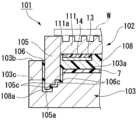
도 1은 정전 척 장치(1)의 단면도이다. 본 실시형태의 정전 척 장치(1)는 평면에서 볼 때 원 형상을 갖고 있다. 정전 척 장치(1)는, 상면이 반도체 웨이퍼 등의 판 형상 시료(W)를 재치하는 재치면(19)으로 된 정전 척부(2)와, 정전 척부(2)를 원하는 온도로 조정하는 온도 조절용 베이스부(3)와, 정전 척부(2)와 온도 조절용 베이스부(3)를 접착 일체화하는 접착층(8)과, 급전용 단자(15)와, 유기 절연층(제2 유기 절연층)(7)을 구비하고 있다.1 is a sectional view of an
이하의 설명에 있어서는, 재치면(19) 측을 "상", 온도 조절용 베이스부(3) 측을 "하"로서 나타내며, 각 구성의 상대 위치를 나타내는 경우가 있다. 또, 정전 척 장치(1)의 상하 방향으로 연장되는 중심축에 대하여 직경 방향을 기준으로 하여 "외측(또는 직경 방향 외측)" 및 "내측(또는 직경 방향 내측)"으로서, 각부의 위치를 설명한다.In the following description, the
정전 척부(2)는, 한쪽의 면(상면)을 반도체 웨이퍼 등의 판 형상 시료(W)를 재치하는 재치면(19)으로 하는 재치판(세라믹 플레이트)(11)과, 재치판(11)의 재치면(19)과는 반대 측의 면(다른 쪽의 면)에 마련된 정전 흡착용 전극(13)과, 재치판(11)과 정전 흡착용 전극(13)의 사이에 마련된 제1 유기 절연층(14)을 갖고 있다.The
정전 척부(2)의 재치면(19)에는, 직경이 판 형상 시료(W)의 두께보다 작은 돌기부(30)가 복수 개 형성되어 있다. 정전 척 장치(1)는 복수의 돌기부(30)가 판 형상 시료(W)를 지지하는 구성으로 되어 있다. 재치면(19)의 주연에는, 주연벽(17)이 형성되어 있다. 주연벽(17)은, 돌기부(30)와 동일한 높이로 형성되어 있으며, 돌기부(30)와 함께 판 형상 시료(W)를 지지한다.On the
재치판(11)은, 재치면(19)의 반대 측의 하면(11a)의 주연으로부터 온도 조절용 베이스부(3) 측(즉 하측)으로 연장되는 제방부(5)를 갖는다. 제방부(5)는, 재치판(11)의 하면(11a) 측에 위치하는 제1 유기 절연층(14) 및 정전 흡착용 전극(13)을 직경 방향 외측으로부터 감싼다. 본 실시형태에 있어서, 제방부(5)의 평면에서 볼 때 형상은 원환 형상이다. 제방부(5)를 갖는 재치판(11)은, 예를 들면 세라믹 플레이트를 카운터 보링 가공하여, 오목부(11c)를 형성함으로써 성형 가능하다. 제방부(5)의 두께(즉, 정전 척 장치(1)의 직경 방향의 폭치수)는, 0.3mm 이상 1.0mm 이하로 하는 것이 바람직하다. 이와 같은 두께로 함으로써, 충분한 기계적 강도를 확보하면서, 재치판(11)의 열용량을 억제하여 재치판(11)의 온도 응답성을 높일 수 있다.The
제방부(5)가 마련되어 있음으로써, 제1 유기 절연층(14) 및 정전 흡착용 전극(13)의 측면 측은, 전극을 포위하는 접착층(8)을 통하여, 플라즈마에 대한 내구성이 접착층(8)보다 높은 세라믹스로 덮이게 된다. 이로 인하여, 제방부(5)가 없는 경우와 비교하여, 제1 유기 절연층(14) 및 정전 흡착용 전극(13)이 플라즈마로부터 확실히 보호된다. 이 구조에 의하여, 정전 흡착용 전극(13)에 고전압을 인가한 경우에, 제1 유기 절연층(14) 및 정전 흡착용 전극(13)의 측면으로부터 방전되기 어려워, 장치 전체의 내전압을 향상시킬 수 있다.By providing the
제방부(5)의 하측의 선단부(5a)는 온도 조절용 베이스부(3)의 상면(3a)에 마련된 홈부(6)에 수용된다. 즉, 제방부(5)의 선단부(5a)는, 온도 조절용 베이스부(3)의 상면(3a)보다 하측까지 도달하고 있다. 제방부(5)의 하측의 선단부(5a)에는, 모따기(5b, 5d)가 실시되어 있다. 세라믹으로 이루어지는 재치판(11)은 모서리부가 균열의 기점이 되기 쉽다. 제방부의 선단부(5a)에 모따기를 실시함으로써, 예리한 모서리부를 제거하여, 재치판(11)에 균열이 발생하는 것을 억제할 수 있다. 제방부(5)의 선단부(5a)의 모따기 치수는, 일례로서, 0.05mm 이상 0.1mm 이하로 하는 것이 바람직하다. 또한, 도시예의 모따기(5b, 5d)는, 직선적인 모따기 가공이 예시되어 있지만, 둥그스름한 모따기를 실시해도 된다.The
재치판(11)은 임의로 선택되는 재료로 형성할 수 있지만, 산화 알루미늄-탄화 규소(Al2O3-SiC) 복합 소결체, 산화 알루미늄(Al2O3) 소결체, 질화 알루미늄(AlN) 소결체, 산화 이트륨(Y2O3) 소결체 등의, 기계적인 강도를 갖고, 또한 부식성 가스 및 그 플라즈마에 대한 내구성을 갖는 절연성의 세라믹스 소결체로 이루어지는 것이 바람직하다.The
세라믹스 소결체 중의 세라믹스 입자의 평균 입경은 임의로 선택할 수 있는데, 10μm 이하가 바람직하고, 5μm 이하가 보다 바람직하며, 2μm 이하가 더 바람직하다. 정전 척부(2)의 재치면(19)에 마련되는 돌기부(30)의 형성 과정에서는, 샌드블라스트 가공을 행한다. 샌드 블레스트 공정은, 재치면(19)의 표면에 연마제 등을 분사하여, 굴삭하는 공정이다. 이로 인하여, 돌기부(30)의 내부에 크랙이 잔류하는 경우가 있다. 크랙은, 샌드 블레스트 공정 후에 행해지는 버프 연마에 의하여, 강제적으로 진행되고, 사전에 제거된다.The average particle diameter of the ceramic particles in the ceramic sintered body can be arbitrarily selected, but is preferably 10 μm or less, more preferably 5 μm or less, and still more preferably 2 μm or less. In the process of forming the
크랙은, 세라믹 소결체 중의 세라믹 입자의 입계에 형성되기 쉽다. 따라서, 세라믹 입자의 입경이 큰 경우에는, 버프 연마를 거침으로써, 입계를 따라 크게 모서리부가 제거된다. 세라믹 입자의 입경이 커질수록, 돌기부(30)는 보다 둥그스름한 형상이 된다. 이후 단락에 있어서 설명하는 바와 같이, 본 실시형태의 돌기부(30)는, 높이 방향으로 단면적의 변화가 없는 것이 바람직하다. 이로 인하여, 돌기부(30)는 둥그스름하지 않은 것이 바람직하다. 세라믹스 입자의 평균 입경은 10μm 이하(보다 바람직하게는 2μm 이하)로 함으로써, 높이 방향을 따른 단면적의 변화를 억제한 돌기부(30)를 재치면(19)에 형성할 수 있다.Cracks tend to form in grain boundaries of ceramic particles in the ceramic sintered body. Therefore, when the grain size of the ceramic grain is large, the corner portion is largely removed along the grain boundary by buffing. As the particle diameter of the ceramic particles increases, the protruding
재치판(11)의 상면으로부터 정전 흡착용 전극(13)의 하면까지의 두께, 즉 정전 척부(2)의 두께는 임의로 선택할 수 있는데, 0.3mm 이상 또한 5.0mm 이하가 바람직하다. 정전 척부(2)의 두께가 0.3mm 이상이면, 정전 척부(2)의 기계적 강도를 충분히 확보할 수 있다. 한편, 정전 척부(2)의 두께가 5.0mm 이하이면, 정전 척부(2)의 열용량이 과도하게 커지는 일이 없어, 재치되는 판 형상 시료(W)의 열응답성이 열화되지 않는다.The thickness from the upper surface of the
또, 정전 척 장치에 따라서는, 정전 흡착용 전극(13)과 온도 조절용 베이스부(3)의 사이에, 복수의 존으로 분할된 히터를 마련하여, 판 형상 시료(W)의 면내의 온도 분포를 제어하는 구성을 채용하는 경우가 있다. 이와 같은 정전 척 장치에 있어서는, 정전 척부(2)의 두께가 5.0mm를 상회하면, 정전 척부(2)의 가로 방향의 열전도의 증가에 의하여, 판 형상 시료(W)의 면내 온도를 원하는 온도 패턴으로 유지하는 것이 곤란해지는 경우가 있다.In addition, depending on the electrostatic chuck device, a heater divided into a plurality of zones is provided between the
재치판(11)의 두께는 임의로 선택할 수 있는데, 0.3mm 이상 또한 1.0mm 이하가 바람직하다. 재치판(11)의 두께가 0.3mm 이상이면, 정전 흡착용 전극(13)에 인가된 전압에 의하여 재치판(11)의 절연이 파괴되어 방전되는 경우가 없다. 또, 재치판(11)의 두께가 0.3mm 이상이면, 가공 시에 파손되어 균열이 발생하지 않는다. 한편, 1.0mm 이하이면, 판 형상 시료(W)를 원하는 강도로 충분히 흡착 고정할 수 있다.Although the thickness of the
제1 유기 절연층(14)은 절연성 및 내전압성을 갖는 수지층이다. 제1 유기 절연층(14)은, 필름 형상 또는 시트 형상의 형성 재료를 접착하여 형성하는 것이 바람직하다. 제1 유기 절연층(14)은, 도시하지 않은 접착층을 통하여 재치판(11)의 하면에 접착되어 있다. 또한, 제1 유기 절연층(14)과 재치판(11)의 사이의 검은 선을 접착층으로서 볼 수도 있다. 정전 흡착용 전극(13)에 인가되는 고전압에 대하여, 재치판(11)과 제1 유기 절연층(14)이 협동하여, 절연 파괴되지 않는 내전압(절연 파괴 전압, (단위: kV))을 나타낸다.The first organic insulating
제1 유기 절연층(14)의 두께는 임의로 선택할 수 있는데, 0.05mm 이상 또한 0.2mm 이하가 바람직하다. 이 제1 유기 절연층(14)의 두께는, 제1 유기 절연층(14)과 재치판(11)을 접착하는 접착층, 및 제1 유기 절연층(14)과 정전 흡착용 전극(13)을 접착하는 접착층을 포함하는 두께이다. 제1 유기 절연층(14)의 두께가 0.05mm 이상이면, 정전 흡착용 전극(13)에 인가된 전압에 의하여 정전 흡착용 전극(13)과 재치판(11)의 절연이 파괴되어, 방전되는 경우가 없다. 한편, 0.2mm 이하이면, 정전 흡착용 전극(13)과 판 형상 시료(W)의 거리가 너무 멀어지지 않아, 판 형상 시료(W)를 원하는 강도로 충분히 흡착 고정할 수 있다.The thickness of the first organic insulating
제1 유기 절연층(14)의 절연 파괴 전압은 5kV 이상인 것이 바람직하다. 제1 유기 절연층(14)의 형성 재료로서는, 예를 들면 상술한 제1 유기 절연층(14)의 두께에 있어서, 원하는 절연 파괴 전압을 실현할 수 있는 절연 파괴의 강도(단위: kV/mm)를 나타내는 재료를 이용하는 것이 바람직하다. 또, 정전 척 장치(1)의 사용 환경에 있어서의 온도에서, 열화나 변형을 발생시키지 않을 정도의 내열성을 갖는 것이면 된다. 제1 유기 절연층(14)의 형성 재료로서는, 예를 들면 폴리이미드 수지, 실리콘 수지, 에폭시 수지 등을 들 수 있다.The dielectric breakdown voltage of the first organic insulating
일반적으로, 제1 유기 절연층(14)의 이들 형성 재료는, 재치판(11)의 형성 재료인 세라믹스보다 절연 파괴의 강도가 크다. 예를 들면, 폴리이미드 수지의 절연 파괴의 강도는, 300kV/mm이며, 재치판(11)의 형성 재료인 Al2O3-SiC의 절연 파괴의 강도(10kV/mm)와 비교하면 매우 강하다. 이로 인하여, 재치판(11)과 제1 유기 절연층(14)의 적층체를 이용한 경우, 재치판(11)만을 이용한 경우와 비교하여, 이들이 동일한 두께이더라도, 보다 큰 절연 파괴 전압으로 할 수 있다.In general, these materials for forming the first organic insulating
또한, 재치판(11)에 있어서, 만일 핀홀 결함을 발생시키기 쉬운 취약 개소가 존재하고 있던 경우, 재치판(11)만을 이용한 구성에서는, 정전 흡착용 전극(13)에 고전압을 인가하면, 상기 취약 개소에 핀홀이 발생하기 쉽고, 그 결과, 절연 파괴되기 쉽다.In addition, in the case where there is a weak spot in the
한편, 재치판(11)과 제1 유기 절연층(14)의 적층체를 이용한 경우에는, 절연 파괴되기 어렵다. 즉, 재치판(11)의 취약 개소와, 제1 유기 절연층(14)의 취약 개소가, 우발적으로 평면적으로 중첩되어, 취약 개소의 중첩이 발생한 경우에 비로소, 적층체 전체적으로, 핀홀 결함이 발생하기 쉬운 개소가 형성된다. 이로 인하여, 재치판(11)이나 제1 유기 절연층(14)에 취약 개소가 있었다고 해도, 문제가 발생하기 어렵다.On the other hand, when a laminate of the
제1 유기 절연층(14)의 면내의 두께의 편차는 50μm 이내가 바람직하고, 10μm 이내가 보다 바람직하다. 제1 유기 절연층(14)의 면내의 두께의 편차가 50μm 이하이면, 두께의 대소에 따라 온도 분포에 고저의 차가 발생하기 어렵다. 그 결과, 제1 유기 절연층(14)의 두께 조정에 의한 온도 제어에 악영향을 주기 어려워, 바람직하다. 또, 흡착력이 재치면(19)의 면내에서 불균일해지기 어려워 바람직하다.The in-plane thickness variation of the first organic insulating
제1 유기 절연층(14)의 열전도율은, 0.05W/mk 이상이 바람직하고, 0.1W/mk 이상이 보다 바람직하다. 열전도율이 0.05W/mk 이상이면, 정전 척부(2)로부터 온도 조절용 베이스부(3)에 대한 제2 유기 절연층(7)을 통한 열전도가 용이하여, 냉각 속도가 저하되지 않아, 바람직하다. 또, 제1 유기 절연층(14)의 열전도율은, 재치판(11)과 정전 흡착용 전극(13)의 열전달률이 >750W/m2K, 보다 바람직하게는 >4000W/m2K가 되도록 제어되어 있으면 된다.The thermal conductivity of the first organic insulating
정전 흡착용 전극(13)은, 전하를 발생시켜 정전 흡착력으로 판 형상 시료(W)를 고정하기 위한 정전 척용 전극으로서 이용된다. 용도에 따라, 전극의 형상이나, 크기가, 적절히 조정된다. 예를 들면, 정전 흡착용 전극(13)은, 정전 흡착용 전극(13)이 형성되는 계층 부분에, 소정의 패턴을 갖는 전극으로서 마련된다. 또한, 정전 흡착용 전극(13)은, 패턴을 갖지 않는, 이른바 솔리드 전극으로서 마련되어 있어도, 기능한다.The electrode for
정전 흡착용 전극(13)은 임의의 방법으로 형성해도 된다. 예를 들면, 정전 흡착용 전극(13)은, 제1 유기 절연층(14)에, 정전 흡착용 전극(13)의 형성 재료인 비자성의 금속박을 접착함으로써, 또는 스퍼터나 증착에 의하여 성막함으로써도 형성할 수 있다. 그 외에도, 정전 흡착용 전극(13)의 형성 재료인 도전성 재료와, 유기물과의 복합 재료를, 스크린 인쇄 등의 도공법을 이용하여 도포함으로써, 형성할 수 있다. 또, 정전 흡착용 전극(13)은 재치판(11)의 내부에 설치되어 있어도 된다.The
정전 흡착용 전극(13)은, 임의로 선택되는 재료로 형성되어도 된다. 예를 들면, 이 전극은, 산화 알루미늄-탄화 탄탈럼(Al2O3-Ta4C5) 도전성 복합 소결체, 산화 알루미늄-텅스텐(Al2O3-W) 도전성 복합 소결체, 산화 알루미늄-탄화 규소(Al2O3-SiC) 도전성 복합 소결체, 질화 알루미늄-텅스텐(AlN-W) 도전성 복합 소결체, 질화 알루미늄-탄탈럼(AlN-Ta) 도전성 복합 소결체, 또는 산화 이트륨-몰리브데넘(Y2O3-Mo) 도전성 복합 소결체 등의 도전성 세라믹스, 혹은 텅스텐(W), 탄탈럼(Ta), 및, 몰리브데넘(Mo) 등의 고융점 금속에 의하여 형성할 수 있다. 또, 정전 흡착용 전극(13)은, 구리(Cu), 알루미늄(Al), 또는 탄소(C)에 의하여 형성할 수도 있다. 이들은 단체(單體), 혹은 2개 이상을 조합하여 사용해도 된다.The
정전 흡착용 전극(13)의 두께는 임의로 선택할 수 있으며, 특별히 한정되는 것은 아니지만, 0.1μm 이상 또한 50μm 이하가 바람직하다. 두께가 0.1μm 이상이면, 충분한 도전성을 확보할 수 있다. 한편, 두께가 50μm 이하이면, 정전 흡착용 전극(13)과 재치판(11)의 접합 계면에, 정전 흡착용 전극(13)과 재치판(11)의 사이의 열팽창률차에 기인하는 크랙이 발생하기 어렵다.The thickness of the
정전 흡착용 전극(13)의 크기는 임의로 선택할 수 있다. 예를 들면, 평면에서 볼 때 제1 유기 절연층(14)과 동일한 크기여도 되지만, 평면에서 볼 때 제1 유기 절연층(14)보다 작은 구성으로 해도 된다. 정전 흡착용 전극(13)을 제1 유기 절연층(14)보다 작은 구성으로 함으로써, 정전 흡착용 전극(13)의 단부로부터 장치 외측을 향한 경사 상방에도 제1 유기 절연층(14)이 존재하는 구조가 된다. 이로 인하여, 정전 흡착용 전극(13)의 연직 상방뿐만 아니라, 정전 흡착용 전극(13)의 경사 상방에도 제1 유기 절연층(14)을 마련함으로써, 내전압의 향상의 효과를 얻을 수 있어, 절연 파괴를 억제할 수 있다.The size of the
급전용 단자(15)는, 정전 흡착용 전극(13)에 직류 전압을 인가하기 위하여 마련된 봉 형상의 단자이다. 급전용 단자(15)의 형성 재료는, 내열성이 우수한 도전성 재료이면 특별히 제한되는 것은 아니며, 금속 재료나 도전성 유기 재료를 이용할 수 있다. 급전용 단자(15)의 전기 전도율은 104Ω·cm 이하이면 바람직하다.The
급전용 단자(15)는, 그 열팽창 계수가, 정전 흡착용 전극(13)의 열팽창 계수에 근사한 것이 바람직하다. 예를 들면, 정전 흡착용 전극(13)을 구성하고 있는 도전성 세라믹스, 혹은 텅스텐(W), 탄탈럼(Ta), 몰리브데넘(Mo), 나이오븀(Nb), 코바르 합금 등의 금속 재료가 적합하게 이용된다. 급전용 단자(15)는, 절연성을 갖는 애자(碍子)(23)에 의하여 온도 조절용 베이스부(3)에 대하여 절연되어 있다.It is preferable that the thermal expansion coefficient of the terminal 15 for power supply approximates the thermal expansion coefficient of the
온도 조절용 베이스부(3)는, 정전 흡착용 전극(13)의 재치판(11) 측과는 반대 측(정전 흡착용 전극(13)의 하방)에 배치되고, 재치판(11)을 냉각시켜 원하는 온도로 조정한다. 온도 조절용 베이스부(3)는 두께가 있는 원판 형상을 갖고 있다. 또, 온도 조절용 베이스부(3)는, 상방으로부터의 평면에서 볼 때 정전 척부(2)(정전 흡착용 전극(13) 및 제1 유기 절연층(14))보다 크게 형성되어 있다.The temperature control base 3 is disposed on the opposite side of the
온도 조절용 베이스부(3)로서는, 예를 들면 그 내부에 물을 순환시키는 유로(도시하지 않음)가 형성된 수랭 베이스 등이 적합하다.As the base part 3 for temperature regulation, the water cooling base etc. which formed the flow path (not shown) which circulates water in the inside are suitable, for example.
온도 조절용 베이스부(3)에는, 재치판(11)의 제방부(5)의 하측에 위치하는 선단부(5a)를 수용하는 홈부(6)가 마련되어 있다. 홈부(6)는, 평면에서 볼 때 제방부(5)와 중첩되는 위치에 배치되고, 제방부(5)보다 폭넓게 형성되어 있다. 홈부(6)와 제방부(5)의 사이에는, 간극이 마련되어 있으며, 이 간극에는, 접착층(8)의 일부인 충전부(8a)가 마련되어 있다.The base part 3 for temperature regulation is provided with the
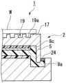
또한 상기 충전부(8a)의 외부로 노출되는 부분에는, 도 5에 나타내는 바와 같이, O링(24)이 마련되어도 된다. 상기 충전부의 외부로 노출되는 부분이, O링으로 덮임으로써, 또한 플라즈마의 침입을 방지하고, 충전부의 에칭 속도가 저하되어, 정전 척 장치의 수명을 길게 할 수 있다. O링의 소재나 사이즈나 단면 형상은 임의로 선택할 수 있으며, 바람직하게는 고무 또는 엘라스토머 수지 등의 탄성체로 이루어지는, 환상의 시일 부재가 사용된다. 또한, 본 실시형태에 있어서는, 시일 부재로서 단면이 원형인 O링을 채용한 경우를 예시했지만, 이에 한정되지 않는다. 특히, 본 실시형태에 나타내는 바와 같이 시일 부재가 수용되는 공간의 단면 형상이 직사각 형상인 경우에는, 단면 직사각 형상의 패킹을 이용함으로써, 접촉 면적을 증가시켜, 플라즈마의 침입을 보다 효과적으로 억제해도 된다.Furthermore, as shown in FIG. 5, an O-
홈부(6)의 깊이는 임의로 선택할 수 있는데, 0.5mm 이상 12.0mm 이하로 하는 것이 바람직하다. 또, 홈부(6)의 폭(즉 정전 척 장치(1)의 직경 방향을 따르는 폭치수)도 임의로 선택할 수 있는데, 0.5mm 이상 1.2mm 이하로 하는 것이 바람직하다. 또한, 홈부(6)의 깊이 방향에 있어서, 제방부(5)는 선단부(5a)로부터 0.3mm 이상 10.0mm 이하의 부분이, 홈부(6)의 내측에, 즉 홈부의 내부에, 위치하고 있는 것이 바람직하다.Although the depth of the
이와 같은 치수로 함으로써, 홈부(6)와 제방부(5)의 사이에 충전된 충전부(8a)의 두께를 충분히 확보하여, 이후 단락에 있어서 설명하는 바와 같이 정전 척 장치(1)의 장수명화를 도모할 수 있다.By setting such dimensions, a sufficient thickness of the charging
또한, 본 실시형태에 있어서, 온도 조절용 베이스부(3)의 상면(3a)으로서, 홈부(6)의 내측에 위치하는 부분과, 외측에 위치하는 부분의 높이는, 서로 일치하고 있다. 그러나, 이들 한쪽의 부분이 상측, 다른 쪽의 부분이 하측에 위치하고 있어도 된다. 즉, 온도 조절용 베이스부(3)의 상면은, 서로 높이가 다른 복수의 상면을 갖고 있어도 된다.Moreover, in this embodiment, as the
온도 조절용 베이스부(3)를 구성하는 재료로서는, 열전도성, 도전성, 및 가공성이 우수한 금속, 또는 이들 금속을 포함하는 복합재이면 바람직하게 사용할 수 있고, 특별히 제한은 없다. 예를 들면, 알루미늄(Al), 알루미늄 합금, 구리(Cu), 구리 합금, 스테인리스강(SUS), 타이타늄 등이 적합하게 이용된다. 온도 조절용 베이스부(3) 중 적어도 플라즈마에 노출되는 면은, 알루마이트 처리가 실시되어 있거나, 혹은 알루미나 등의 절연막이 성막되어 있는 것이 바람직하다.As the material constituting the base portion 3 for temperature regulation, a metal having excellent thermal conductivity, conductivity, and workability, or a composite material containing these metals can be preferably used, and is not particularly limited. For example, aluminum (Al), aluminum alloy, copper (Cu), copper alloy, stainless steel (SUS), titanium, etc. are suitably used. It is preferable that at least the surface of the base part 3 for temperature regulation exposed to plasma is subjected to an alumite treatment, or an insulating film such as alumina is formed.
제2 유기 절연층(7)은 임의로 선택할 수 있는데, 절연성 및 내전압성을 갖는 필름 형상 또는 시트 형상의 수지인 것이 바람직하고, 온도 조절용 베이스부(3)와 정전 흡착용 전극(13)의 사이에 마련되어 있다. 본 실시형태에 있어서는, 제2 유기 절연층(7)은, 도시하지 않은 접착층을 통하여, 온도 조절용 베이스부(3)의 상면에 접착되어 있다. 또한 제2 유기 절연층(7)과 온도 조절용 베이스부(3)의 사이의 검은 선을 접착층으로서 봐도 된다.The second organic insulating
본 실시형태의 정전 척 장치(1)에 있어서, 강한 정전 흡착력을 얻기 위하여 정전 흡착용 전극(13)에 고전압을 인가한 경우, 정전 흡착용 전극(13)으로부터 상방에 대해서는, 재치판(11)과 제1 유기 절연층(14)이 협동하여, 높은 내전압을 실현하고 있다. 한편, 정전 흡착용 전극(13)으로부터 하방에 대해서는, 정전 흡착용 전극(13)에 고전압을 인가하면, 내전 부재가 없는 경우, 정전 흡착용 전극(13)과 온도 조절용 베이스부(3)의 사이에서 절연 파괴되어, 방전될 가능성이 발생한다. 그러나, 본 실시형태의 정전 척 장치(1)에서는, 제2 유기 절연층(7)이 마련되어 있다. 제2 유기 절연층(7)을 마련함으로써, 정전 흡착용 전극(13)에 인가되는 고전압에 의하여, 정전 흡착용 전극(13)과 온도 조절용 베이스부(3)의 사이에서 방전이 일어나지 않도록, 절연되어 있다.In the
제2 유기 절연층(7)은, 상술한 제1 유기 절연층(14)과 동일한 구성(형성 재료, 두께)으로 할 수 있다. 그러나, 제1 유기 절연층(14) 및 제2 유기 절연층(7)은, 동일한 구성이어도 되고, 다른 구성이어도 된다.The second organic insulating
제1 유기 절연층(14) 및 제2 유기 절연층(7)을 형성하고 있는 접착재는 임의로 선택할 수 있다. 예를 들면, 폴리이미드 수지, 실리콘 수지, 및 에폭시 수지 등으로 이루어지는, 내열성 및 절연성을 갖는 시트 형상 또는 필름 형상의 접착성 수지를 바람직하게 사용할 수 있으며, 두께는 5μm~100μm가 바람직하고, 보다 바람직하게는 10μm~50μm이다.The adhesive material forming the first organic insulating
접착재의 면내의 두께의 편차는 10μm 이내인 것이 바람직하다. 접착재의 면내의 두께의 편차가 10μm 이내이면, 온도 조절용 베이스부(3)에 의한 정전 척부(2)의 온도 제어의 정밀도가, 면내에서 허용 범위에 들어가, 정전 척부(2)의 재치면(19)에 있어서의 면내 온도를 균일하게 할 수 있다.It is preferable that the variation of the in-plane thickness of the adhesive material is within 10 μm. If the in-plane thickness variation of the adhesive material is within 10 μm, the precision of the temperature control of the
접착층(8)은, 정전 척부(2)의 하면과 온도 조절용 베이스부(3)의 상면의 사이에 개재된다. 이 접착층(8)은, 제1 유기 절연층(14), 정전 흡착용 전극(13), 및 제2 유기 절연층(7)의 측면을 덮고 있으며, 정전 척부(2)와 온도 조절용 베이스부(3)를 접착 일체화하고 있다. 또, 접착층(8)은 열응력의 완화 작용을 갖는다.The
접착층(8)은, 위치에 따라, 충전부(8a)와 개재부(8b)와 전극 포위부(8c)의, 3개의 영역으로 분류된다.The
즉, 접착층(8)은, 충전부(8a), 개재부(8b), 및 전극 포위부(8c)를 갖는다. 접착층(8)의 각부(즉, 충전부(8a), 개재부(8b) 및 전극 포위부(8c))의 두께는, 특별히 한정되지 않고 임의로 선택할 수 있는데, 100μm 이상 또한 200μm 이하가 바람직하다.That is, the
충전부(8a)는, 온도 조절용 베이스부(3)의 홈부(6)의 내부에 충전되어, 홈부(6)와 제방부(5)의 사이의 간극을 채우고 있다. 보다 구체적으로는, 충전부(8a)는, 제방부(5)의 선단부(5a)의 하측, 및 제방부(5)에 대하여 직경 방향 내측 및 직경 방향 외측에 위치하고 있다.The filling
충전부(8a)는, 제방부(5)의 외측에 있어서 외부로 노출되는 노출부(8d)를 갖는다. 접착층(8)은, 반도체 제조 공정의 플라즈마가 조사됨으로써 노출부(8d)가 에칭되어, 노출부(8d)가 후퇴, 즉 하측으로 노출부가 이동한다. 충전부(8a)는, 제방부(5)의 선단부(5a)의 근방을 감싸 감아 넣어진, 형상을 갖는다. 이로 인하여, 에칭 경로를 길게 할 수 있어, 충전부(8a)가 완전하게 소실되는 데에 필요한 시간을 길게 할 수 있다. 즉, 예를 들면 에칭이 진행되어 정전 흡착용 전극(13)이 노출되기까지의 시간을 길게 할 수 있어, 정전 척 장치(1)를 장수명화할 수 있다.The charging
이에 더하여, 충전부(8a)에서는, 에칭이 진행되어 노출부(8d)가 후퇴함에 따라, 노출부(8d)에 플라즈마가 도달하기 어려워진다. 예를 들면, 접착층(8)에 있어서 충전부(8a)의 당초의 노출 부분이 에칭되어 소실되어 가면, 홈부(6)와 제방부(5)에 의하여 형성된 U자 형상의 경로의 안쪽에, 노출부(8d)가 형성된 상태가 된다. 이 상태에 있어서는, U자 형상의 경로를 거쳐 이동하는 플라즈마는, U자 형상의 경로의 내측을 따라, 하측, 직경 방향 내측, 상측으로, 순서대로 진행 방향을 변경하여, 노출부(8d)에 도달하지 않으면, 노출부(8d)의 에칭을 행할 수 없다. 이로 인하여, 에칭의 속도가 현저하게 저하되어, 결과적으로, 정전 척 장치(1)의 수명을 길게 할 수 있다.In addition to this, in the charging
또, 충전부(8a)는, 제방부(5)를, 직경 방향 내외로부터 협지하도록, 또한 하부에서 연결하도록, 배치되어 있다. 이 배치에 의하여, 충전부(8a)의 열팽창 또는 열수축에 의한 응력을 서로 상쇄하여, 제방부(5)에 부여하는 부하를 경감시킬 수 있다.In addition, the filling
개재부(8b)는, 정전 흡착용 전극(13)과 온도 조절용 베이스부(3)의 사이에 위치하고 있다. 개재부(8b)는, 정전 척부(2)와 온도 조절용 베이스부(3)의 접착 일체화, 열응력의 완화, 및 열의 전달을 주된 기능으로 한다. 개재부(8b)는, 그 내부, 정전 척부(2)와의 계면 및 온도 조절용 베이스부(3)와의 계면에, 공극이나 결함이 없거나 적은 것이 바람직하다. 공극이나 결함의 형성이 없거나, 또는 적으면, 열전도성이 저하되지 않아, 판 형상 시료(W)의 면내 온도 분포가 균일해져 바람직하다.The intervening
전극 포위부(8c)는, 정전 흡착용 전극(13)의 주연과 제방부(5)의 사이에 위치하여, 정전 흡착용 전극(13)을 포위한다. 전극 포위부(8c)는 충전부(8a)의 상방에 위치하고 있다. 전극 포위부(8c)는, 정전 흡착용 전극(13)의 주위를 감싼다. 전극 포위부(8c)가 마련되어 있음으로써, 접착층(8)의 에칭이 진행되어 정전 흡착용 전극(13)이 노출될 때까지의 시간을 길게 할 수 있다. 이에 더하여 전극 포위부(8c)는, 제1 유기 절연층(14) 및 정전 흡착용 전극(13)의 측면으로부터의 방전을 억제하여, 장치 전체의 내전압을 향상시킨다.The
접착층(8)은 임의로 선택되는 재료로 형성할 수 있는데, 예를 들면 실리콘계 수지 조성물을 가열 경화시킨 경화체 또는 아크릴 수지로 형성된다. 접착층(8)은, 유동성 있는 수지 조성물을 정전 척부(2)와 온도 조절용 베이스부(3)의 사이에, 이를 충전한 후에 가열 경화시킴으로써 형성하는 것이 바람직하다.The
접착층(8)은, 단일의 수지 재료로 구성해도 되는데, 서로 다른 부위로 구분된 2종류 이상의 수지 재료로 구성해도 된다. 이 경우, 예를 들면 이하의 구성을 바람직한 예로서 들 수 있다.The
접착층(8)을, 서로 다른 부위를 구성하는, 제1 수지 재료와, 제2 수지 재료로 형성한다. 제2 수지 재료는, 제1 수지 재료와 비교하여 내플라즈마성이 우수한 재료로 이루어진다. 제2 수지 재료로 구성되는 부위는, 제1 수지 재료로 구성되는 부위보다, 접착층(8)이 외부로 노출되는 부분인 노출부(8d)에 가까운 측에 위치한다. 그 일례로서, 접착층(8)의 충전부(8a) 및 전극 포위부(8c)가 제2 수지 재료로 구성되며, 개재부(8b)가 제1 수지 재료로 구성되는 구성을 들 수 있다. 다른 예로서, 접착층(8)의 충전부(8a)만이 제2 수지 재료로 구성되며, 개재부(8b) 및 전극 포위부(8c)가 제1 수지 재료로 구성되는 구성을 들 수 있다. 또한, 다른 예로서, 충전부(8a)의 노출부(8d) 측의 일부만이 제2 수지 재료로 구성되는 예를 들 수 있다. 즉, 제2 수지 재료로 이루어지는 부위는, 적어도 노출부(8d)를 포함하는, 다른 영역과 연속된 영역인 것이 바람직하다. 접착층(8)은, 노출부(8d)를 포함하는 부위를 제2 수지 재료로 구성함으로써, 플라즈마에 의한 에칭의 진행을 지연시킬 수 있어, 정전 척 장치(1)의 수명을 길게 할 수 있다.The
제1 수지 재료는, 적어도 개재부(8b)를 포함하는 부위를 구성하는 것이 바람직하다. 이 경우, 제1 수지 재료는, 제2 수지 재료와 비교하여, 접착력이 강한 재료로 하는 것이 바람직하다. 이 구성에 의하여, 개재부(8b)에 의하여 정전 척부(2)와 온도 조절용 베이스부(3)를 강고하게 접착할 수 있다.The first resin material preferably constitutes a portion including at least the intervening
이와 같이, 접착층(8)을, 각각 다른 기능을 바람직하게 필요로 하는 각부위에 맞춘 다른 재료로 구성함으로써, 정전 척 장치(1)의 장수명화에 기여할 수 있다.In this way, by configuring the
온도 조절용 베이스부(3)의 상면 및 정전 척부(2)의 하면은 반드시 평탄한 것은 아니다. 유동성의 수지 조성물을, 홈부(6)을 포함하는 온도 조절용 베이스부(3)와 정전 척부(2)의 사이에 충전시킨 후에 경화시켜, 접착층(8)을 형성함으로써, 즉 정전 척부(2)와 온도 조절용 베이스부(3)의 형상을 따라 형상을 변경하는 수지 조성물을 이용함으로써, 정전 척부(2)와 온도 조절용 베이스부(3)의 요철에 기인하여 접착층(8)과의 사이에 공극이 발생하는 것을 억제할 수 있다. 이로써, 공극이 없거나 혹은 적기 때문에, 접착층(8)의 열전도 특성을 면내에서 균일하게 할 수 있어, 정전 척부(2)의 균열성을 높일 수 있다.The upper surface of the temperature control base part 3 and the lower surface of the
또, 정전 척 장치(1)에는, 장치 전체를 두께 방향으로 관통하는, 냉각 가스 도입 구멍(관통 구멍)(18)이 형성되어 있다. 냉각 가스 도입 구멍(18)으로부터는, He 등의 냉각 가스가 공급된다. 냉각 가스는, 정전 척부(2)의 재치면(19)과 판 형상 시료(W)의 하면의 간극을 흐른다. 이 흐름에 의하여 재치면(19)과 판 형상 시료(W)의 사이의 열전달률을 높임으로써, 판 형상 시료(W)의 온도를 낮추는 작용을 한다. 재치판(11)의 주연벽(17)은, 재치면(19)과 판 형상 시료(W)의 사이에 도입되는 냉각 가스의 누출을 억제한다. 냉각 가스 도입 구멍(18)이 형성되어 있음에 따라, 재치판(11)에도, 재치판(11)의 두께 방향으로 관통하는 제1 관통 구멍(11h)이 마련되어 있다. 정전 흡착용 전극(13)은, 냉각 가스 도입 구멍(18)을 피하여 형성되어 있다. 제1 유기 절연층(14)에는, 제1 유기 절연층(14)의 두께 방향으로 관통하고, 제1 관통 구멍(11h)과 연통하는 제2 관통 구멍(14h)이 마련되어 있다. 제2 관통 구멍(14h)은, 평면에서 볼 때 제1 관통 구멍(11h)보다 크게 형성되어 있다. 정전 흡착용 전극(13)의 측면(도면 중, 부호 13h로 나타냄) 및 제2 관통 구멍(14h)의 측면은, 접착층(8)에 의하여 덮여 있다. 또한, 제2 유기 절연층(7)에는, 제2 유기 절연층(7)의 두께 방향으로 관통하는 관통 구멍(7h)이 마련되어 있다.In addition, the
그 외에 정전 척 장치(1)는, 판 형상 시료(W)를 밀어 올리는 리프트 핀을 삽통시키기 위한 복수의 관통 구멍이 마련되어 있어도 된다. 또한, 재치판(11)의 하면(11a)에 장착되어, 재치판(11)을 가열하기 위한 히터가 마련되어 있어도 된다.In addition, the
본 실시형태의 정전 척 장치(1)는 이상과 같은 구성으로 되어 있다.The
본 실시형태의 정전 척 장치(1)에 의하면, 온도 조절용 베이스부(3)의 홈부(6)에 재치판(11)의 제방부(5)의 선단부(5a)가 수용되어 있다. 이로써, 재치판(11)과 온도 조절용 베이스부(3)의 사이의 간극에 충전된 접착층(8)의 충전부(8a)가, 제방부(5)의 표면을 따라 감아 넣어진 래비린스 구조를 갖는다. 충전부(8a)는, 제방부(5)의 외측에 있어서, 외부로 노출되는 노출부(8d)를 갖고 있다. 반도체 제조의 공정에 있어서, 충전부(8a)의 노출부(8d)는, 플라즈마에 의하여 에칭되어, 서서히 후퇴한다. 본 실시형태에 의하면, 충전부(8a)로부터 정전 흡착용 전극(13)까지의 경로가 길어진다. 이로 인하여, 에칭이 진행된 경우이더라도, 정전 흡착용 전극(13)이 노출되기 어려워, 정전 흡착용 전극(13)으로부터의 방전을 방지할 수 있다. 이에 더하여, 충전부(8a)가 감아 넣어진 래비린스 구조로 되어 있음으로써, 충전부(8a)의 노출부(8d)가 후퇴한 경우에, 감아 넣어진 곳 앞에 노출부(8d)가 위치하게 되기 때문에 플라즈마가 노출부(8d)에 도달하기 어려워, 충전부(8a)의 에칭을 지연시킬 수 있다.According to the
제방부(5)는 폐환 형상을 갖는 것이 바람직하다. 또, 홈부(6)는 제방부(5)에 대응하는 폐환 형상의 홈인 것이 바람직하다. 제방부(5) 및 홈부(6)를 폐환 형상으로 함으로써, 재치판(11)과 온도 조절용 베이스부(3)의 사이의 접착층(8)을 전체 둘레에 걸쳐서, 감아 넣어진 형상으로 할 수 있다. 이로 인하여, 정전 흡착용 전극(13)의 노출을 확실히 지연시킬 수 있다. 따라서, 정전 척 장치(1)의 수명을 길게 할 수 있다.The
제1 실시형태의 바람직한 예인 변형예를 이하에 설명한다. 변형예의 조건은 서로 조합해도 된다.A modified example that is a preferred example of the first embodiment will be described below. The conditions of the modified examples may be combined with each other.
(변형예 1)(Modification 1)
다음으로 본 발명의 바람직한 예인, 변형예 1의 정전 척 장치(101)에 대하여 설명한다.Next, the
도 2는 정전 척 장치(101)의 부분 단면도이다. 변형예 1의 정전 척 장치(101)는, 상술한 실시형태의 정전 척 장치(1)와 비교하여, 주로 제방부 및 홈부의 구성이 다르다. 또한, 상술한 실시형태와 동일 양태의 구성 요소에 대해서는, 동일 부호를 붙여, 그 설명을 생략하는 경우가 있다.2 is a partial cross-sectional view of the
정전 척 장치(101)는, 정전 척부(102)와 온도 조절용 베이스부(103)와 접착층(108)과 제2 유기 절연층(7)을 구비하고 있다. 정전 척부(102)는, 판 형상 시료(W)를 재치하는 재치판(세라믹 플레이트)(111)과, 정전 흡착용 전극(13)과, 제1 유기 절연층(14)을 갖고 있다. 재치판(111)은, 하면(111a)의 주연으로부터 온도 조절용 베이스부(103) 측(즉 하측)으로 연장되는 제방부(105)를 갖는다. 온도 조절용 베이스부(103)에는, 재치판(111)의 제방부(105)의 하측에 위치하는 선단부(105a)를 수용하는 홈부(106)가 마련되어 있다.The
제방부(105)에는, 온도 조절용 베이스부(103) 측의 선단부(105a)를 향하여, 제방부의 폭(단면에서 본 제방부의 두께)을 단계적으로 얇게 하는 단차가 형성되어 있으며, 그에 따라, 2개의 제방부 측 단차면(105c)이 마련되어 있다. 본 예에서는, 단면에서 보아, 3개의 단차가 마련되어 있다. 제방부 측 단차면의 수는 임의로 선택할 수 있으며, 예를 들면 1이나 2나 3이나 4 등을 예로서 들 수 있다. 또한, 여기에서는, 선단부(105a)는 제방부 측 단차면에 포함시키지 않는다. 본 변형예에 있어서, 2개의 제방부 측 단차면(105c)은, 제방부(105)의 선단부(105a)에 대하여, 제방부(105)의 내측 부분에 위치하고, 계단 형상의 구조를 제방부에 부여한다. 2개의 제방부 측 단차면(105c)은 각각 하측을 향하는 면이다. 제방부 측 단차면의 폭, 제방부 측 단차면 간의 거리, 및 단차의 수는, 임의로 선택할 수 있다.In the
홈부(106)에는, 2개의 제방부 측 단차면(105c)에 대응하여, 바닥측을 향하여 홈부의 폭을 좁게 하는, 2개의 홈부 측 단차면(106c)이 마련되어 있다. 홈부 측 단차면(106c)은 각각 상측을 향하는 면이다. 홈부 측 단차면(106c)은 제방부 측 단차면(105c)과 상하 방향으로 대향하고 있다.The
홈부(106)와 제방부(105)의 사이에는, 간극이 마련되어 있다. 이 간극에는, 접착층(108)의 일부인 충전부(108a)가 마련되어 있다. 본 변형예에 의하면, 제방부(105) 및 홈부(106)에, 서로 대향하는 단차면(105c, 106c)이 마련되어 있기 때문에, 충전부(108a)가 충전되어 있는 간극이 만드는 경로가 길어진다. 이로써, 충전부(108a)가 완전하게 소실되기까지 필요한 시간을 길게 할 수 있어, 정전 척 장치(101)를 장수명화할 수 있다.A gap is provided between the
본 변형예에 있어서, 온도 조절용 베이스부(103)의 상면의 일부로서, 홈부(106)의 외측에 위치하는 외측 상면(103b)은, 홈부(106)의 내측에 위치하는 내측 상면(103a)에 대하여, 상측에 위치한다. 이로써, 제방부(105)보다 외측에 있어서, 충전부(108a)의 경로를 보다 길게 할 수 있다. 그러나, 정전 척 장치(101)는, 이와 같은 형태에만 한정되는 것이 아니다. 외측 상면(103b)은, 동일한 높이나 낮은 높이로 마련되어도 된다. 예를 들면, 도 2에 이점 쇄선으로 나타내는 바와 같이, 내측 상면(103a)보다 하측에 위치하는 외측 상면(103c)을 마련해도 된다.In this modification, as a part of the upper surface of the
(변형예 2)(Modification 2)
다음으로 본 발명의 바람직한 예인, 변형예 2의 정전 척 장치(201)에 대하여 설명한다.Next, the
도 3은 정전 척 장치(201)의 부분 단면도이다. 변형예 2의 정전 척 장치(201)는, 변형예 1의 정전 척 장치(101)와 마찬가지로, 제방부 측 단차면 및 홈부 측 단차면의 조합을, 구체적으로는 제방부 측 단차면(205c) 및 홈부 측 단차면(206c)을 갖고 있는데, 마련된 위치와 방향이 다르다. 또한, 상술한 실시형태 및 변형예와 동일 양태의 구성 요소에 대해서는, 동일 부호를 붙여, 그 설명을 생략하는 경우가 있다.3 is a partial cross-sectional view of an
정전 척 장치(201)는, 정전 척부(202)와 온도 조절용 베이스부(203)와 접착층(208)과 제2 유기 절연층(7)을 구비하고 있다. 정전 척부(202)는, 판 형상 시료(W)를 재치하는 재치판(세라믹 플레이트)(211)과, 정전 흡착용 전극(13)과, 제1 유기 절연층(14)을 갖고 있다. 재치판(211)은, 선단부(205a) 측에 2개의 제방부 측 단차면(205c)이 마련된 제방부(205)를 갖는다. 온도 조절용 베이스부(203)에는, 하나의 홈부 측 단차면(206c)이 마련된 홈부(206)가 형성되어 있다. 단차의 수는 임의로 선택할 수 있다.The
본 변형예에 있어서, 제방부 측 단차면(205c)은 2개 마련되어 있다. 2개의 제방부 측 단차면(205c)은, 제방부(205)의 선단부(205a)에 대하여 제방부(205)의 외측 부분에 위치하고 있다. 제방부 측 단차면(205c)은, 하측을 향하는 면이며, 상측을 향하는 홈부 측 단차면(206c)과는 서로 대향하고 있다.In this modified example, two stepped
본 변형예에 있어서, 온도 조절용 베이스부(203)의 상면의 일부로서, 홈부(206)의 외측에 위치하는 외측 상면(203b)은, 홈부(206)의 내측에 위치하는 온도 조절용 베이스부(203)의 내측 상면(203a)에 대하여, 하측에 위치한다. 또, 외측 상면(203b)의 일부는, 하측을 향하는 하나의 제방부 측 단차면(205c)과 대향하고 있다.In this modified example, as a part of the upper surface of the
홈부(206)와 제방부(205)의 사이에는, 간극이 마련되어 있으며, 이 간극에는, 접착층(208)의 일부인 충전부(208a)가 마련되어 있다. 충전부(208a)는, 제방부(205)의 외주면과 온도 조절용 베이스부의 외측 상면(203b)의 사이로부터, 외부로 노출되는 노출부(208d)를 갖는다. 본 변형예의 노출부(208d)의 노출면은, 정전 척 장치(201)의 직경 방향 외측을 향하고 있다.A gap is provided between the
본 변형예에 의하면, 상술한 변형예 1과 마찬가지로, 충전부(208a)가 충전되는 간극의 경로를 길게 하여, 정전 척 장치(201)를 장수명화할 수 있다.According to this modification, as in the above-described
(변형예 3)(Modification 3)
다음으로 본 발명의 바람직한 예인, 변형예 3의 정전 척 장치(301)에 대하여 설명한다.Next, the
도 4는 정전 척 장치(301)의 부분 단면도이다. 변형예 3의 정전 척 장치(301)는, 변형예 1 및 변형예 2의 정전 척 장치(101, 201)와 마찬가지로, 제방부 측 단차면 및 홈부 측 단차면의 조합을, 구체적으로는 제방부 측 단차면(305c) 및 홈부 측 단차면(306c)을, 갖지만, 그 위치나 형상 등의 구성이 다르다. 또한, 상술한 실시형태 및 변형예와 동일 양태의 구성 요소에 대해서는, 동일 부호를 붙여, 그 설명을 생략하는 경우가 있다.4 is a partial cross-sectional view of an
정전 척 장치(301)는, 정전 척부(302)와 온도 조절용 베이스부(303)와 접착층(308)과 제2 유기 절연층(7)을 구비하고 있다. 정전 척부(302)는, 판 형상 시료(W)를 재치하는 재치판(세라믹 플레이트)(311)과, 정전 흡착용 전극(13)과, 제1 유기 절연층(14)을 갖고 있다. 재치판(311)은, 선단부(305a) 측에 제방부 측 단차면(305c)이 마련된 제방부(305)를 갖는다. 온도 조절용 베이스부(303)에는, 제방부 측 단차면(305c)에 대응하는, 즉 대면하는, 홈부 측 단차면(306c)이 마련된 홈부(306)가 형성되어 있다. 단차의 수는 임의로 선택할 수 있다.The
본 변형예에 있어서, 제방부 측 단차면(305c)은 2개 마련되어 있다. 2개의 제방부 측 단차면(305c)은, 제방부(305)의 선단부(305a)에 대하여 제방부(305)의 내측과 외측에 각각 위치하고 있다. 제방부 측 단차면(305c)은, 하측을 향하는 면이며, 온도 조절용 베이스부(303)의 홈부 측 단차면(306c)과는, 상하 방향으로 대향하고 있다. 또한 제방부 측 단차면(305c)의 높이는 서로 다르지만, 동일해도 된다.In this modified example, two stepped
홈부(306)와 제방부(305)의 사이에는, 간극이 마련되어 있으며, 이 간극에는, 접착층(308)의 일부인 충전부(308a)가 마련되어 있다. 본 변형예에 의하면, 상술한 변형예 1 및 변형예 2와 마찬가지로, 충전부(308a)의 수지 재료가 충전되는 간극의 경로를 길게 하여, 정전 척 장치(301)를 장수명화할 수 있다.A gap is provided between the
본 변형예에 있어서, 온도 조절용 베이스부(303)의 상면의 일부로서, 홈부(306)의 외측에 위치하는 외측 상면(303b)은, 홈부(306)의 내측에 위치하는, 온도 조절용 베이스부(303)의 내측 상면(203a)과 동일한 높이를 갖는다. 또, 홈부(306)의 외측 주연에는, 외측 상면(303b)으로부터 상측으로 연장되는 돌출부(303d)가 마련되어 있다. 돌출부(303d)가 마련되어 있음으로써, 제방부(305)보다 외측에 있어서의, 충전부(308a)의 경로를 보다 길게 할 수 있어, 정전 척 장치(301)를 장수명화할 수 있다. 돌출부는, 다른 예에 있어서도, 바람직하게 사용해도 된다.In this modification, as a part of the upper surface of the
이상, 첨부 도면을 참조하면서 본 발명에 관한 적합한 실시의 형태예에 대하여 설명했지만, 본 발명은 이러한 예에 한정되지 않는 것은 말할 필요도 없다. 상술한 예에 있어서 나타낸 각 구성 부재의 모든 형상이나 조합 등은 일례이며, 본 발명의 주지로부터 일탈하지 않는 범위에 있어서 설계 요구 등에 근거하여 다양하게 변경 가능하다.As mentioned above, although the preferred embodiment example concerning this invention was described referring an accompanying drawing, it goes without saying that this invention is not limited to these examples. All shapes, combinations, etc. of each constituent member shown in the above examples are examples, and can be variously changed based on design requirements and the like within a range not departing from the gist of the present invention.
장수명화가 가능한 정전 척 장치를 제공할 수 있다.It is possible to provide an electrostatic chuck device capable of increasing lifespan.
1, 101, 201, 301 정전 척 장치
2, 102, 202, 302 정전 척부
3, 103, 203, 303 온도 조절용 베이스부
3a, 103a, 203a 온도 조절용 베이스부의 상면
5, 105, 205, 305 제방부
5a, 105a, 205a 제방부의 선단부
5b, 5d 모따기
6, 106, 206, 306 홈부
7 제2 유기 절연층
7h 제2 유기 절연층의 관통 구멍
8, 108, 208, 308 접착층
8a, 108a, 208a, 308a 충전부
8b 개재부
8c 전극 포위부
8d, 208d 노출부
11, 111, 211, 311 재치판(세라믹 플레이트)
11a, 111a 재치판의 하면
11c 오목부
11h 재치판의 제1 관통 구멍
13 정전 흡착용 전극
13h 정전 흡착용 전극의 측면
14 제1 유기 절연층
14h 제1 유기 절연층의 제2 관통 구멍
15 급전용 단자
17 재치면의 주연벽
18 냉각 가스 도입 구멍
19 재치면
19a 재치면의 홈부
23 애자
24 O링
30 재치면의 돌기부
103b, 203b, 303b 온도 조절용 베이스부의 외측 상면
103c 온도 조절용 베이스부의 외측 상면
105c, 205c, 305c 제방부 측 단차면
106c, 206c, 306c 홈부 측 단차면
303d 외측 상면의 돌출부
W 판 형상 시료1, 101, 201, 301 electrostatic chuck device
2, 102, 202, 302 electrostatic chuck
3, 103, 203, 303 Base part for temperature control
3a, 103a, 203a Upper surface of the base part for temperature control
5, 105, 205, 305 Embankments
Front end of 5a, 105a, 205a embankment
5b, 5d chamfer
6, 106, 206, 306 Grooves
7 second organic insulating layer
7h through hole of second organic insulating layer
8, 108, 208, 308 adhesive layer
8a, 108a, 208a, 308a live parts
8b interposition
8c electrode enclosure
8d, 208d exposed part
11, 111, 211, 311 plate (ceramic plate)
11a, 111a The lower surface of the plate
11c recess
11h First through hole of plate
13 Electrode for electrostatic adsorption
13h Side of Electrode for Electrostatic Adsorption
14 first organic insulating layer
14h The second through hole of the first organic insulating layer
15 Power supply terminal
17 Peripheral wall of the wit face
18 Cooling gas introduction hole
19 wit
19a Grooves of the etchant surface
23 Agile
24 O-ring
30 Protrusion of the dentition surface
103b, 203b, 303b Outer upper surface of the base part for temperature control
103c Outer upper surface of the base part for temperature control
105c, 205c, 305c Embankment Side Stepped Surface
106c, 206c, 306c Stepped surface on the groove side
303d Exterior upper surface protrusion
W plate shape sample
Claims (10)
Translated fromKorean상기 정전 척부는, 한쪽의 면이 판 형상 시료를 재치하는 재치면인 세라믹 플레이트와, 상기 세라믹 플레이트의 상기 재치면과는 다른 쪽의 면측에 마련된 정전 흡착용 전극을 가지며,
상기 온도 조절용 베이스부는, 상기 정전 흡착용 전극의 상기 세라믹 플레이트 측과는 다른 쪽의 면측에 배치되어, 상기 정전 척부를 냉각시키는 베이스부이고,
상기 세라믹 플레이트는, 상기 온도 조절용 베이스부 측으로 연장되며, 또한 상기 정전 흡착용 전극의 주연을 감싸는, 제방부를 갖고,
상기 온도 조절용 베이스부는, 상기 제방부의 선단부를 수용하는 홈부를 가지며,
상기 홈부와 상기 제방부의 사이에는, 수지 재료로 이루어지는 충전부가 충전된, 정전 척 장치.An electrostatic chuck part and a base part for temperature control are provided,
The electrostatic chuck unit has a ceramic plate, one surface of which is a placement surface for placing a plate-shaped sample, and an electrostatic adsorption electrode provided on a surface side of the ceramic plate other than the placement surface,
the base for temperature control is a base that is disposed on a side of the surface of the electrostatic adsorption electrode that is different from the side of the ceramic plate and cools the electrostatic chuck;
The ceramic plate has an embankment extending toward the temperature control base and surrounding the periphery of the electrostatic adsorption electrode,
The base part for temperature control has a groove part for accommodating the front end of the embankment part,
The electrostatic chuck device of claim 1 , wherein a filling portion made of a resin material is filled between the groove portion and the embankment portion.
상기 제방부가 폐환 형상을 갖고, 상기 홈부가 상기 제방부와 대응하는 폐환 형상의 홈인, 정전 척 장치.According to claim 1,
The electrostatic chuck device of claim 1 , wherein the embankment portion has a closed ring shape, and the groove portion is an annular groove corresponding to the embankment portion.
상기 제방부에는, 상기 온도 조절용 베이스부 측의 선단부를 향함에 따라 제방부의 폭이 단계적으로 얇아지는, 제방부 측 단차가 마련되고,
상기 홈부에는, 상기 제방부 측 단차에 대응하여 바닥측을 향하여 폭이 좁아지는 홈부 측 단차가 마련되어 있는, 정전 척 장치.According to claim 1,
In the embankment, a step on the embankment side is provided, in which the width of the embankment gradually becomes thinner as it goes toward the front end of the base portion for temperature control,
The electrostatic chuck device of claim 1 , wherein the groove portion is provided with a groove-side step that narrows in width toward a floor side corresponding to the embankment-side step.
상기 제방부의 상기 온도 조절용 베이스부 측의 선단부에 모따기가 실시된, 정전 척 장치.According to claim 1,
The electrostatic chuck device according to claim 1 , wherein a chamfer is applied to a distal end of the embankment portion on the side of the base portion for temperature regulation.
상기 충전부의 외부로 노출되는 부분이, O링으로 덮여 있는, 정전 척 장치.According to claim 1,
The electrostatic chuck device of claim 1 , wherein a portion exposed to the outside of the charging unit is covered with an O-ring.
상기 정전 척부와 상기 온도 조절용 베이스부를 접착하는 접착층을 구비하고,
상기 접착층은,
상기 충전부와,
상기 정전 흡착용 전극과 상기 온도 조절용 베이스부의 사이에 위치하는 개재부를 갖는, 정전 척 장치.According to claim 1,
an adhesive layer bonding the electrostatic chuck unit and the temperature control base unit;
The adhesive layer is
the charging unit,
An electrostatic chuck device having an interposition portion positioned between the electrode for electrostatic adsorption and the base portion for temperature control.
상기 접착층이,
제1 수지 재료로 이루어지는 부위와,
상기 제1 수지 재료보다 내플라즈마성이 우수한 제2 수지 재료로 이루어지는 부위로 구분되고,
상기 접착층의 외부로 노출되는 부분이 상기 제2 수지 재료로 이루어지는, 정전 척 장치.According to claim 6,
the adhesive layer,
a portion made of a first resin material;
It is divided into a part made of a second resin material having better plasma resistance than the first resin material,
The electrostatic chuck device of claim 1 , wherein a portion of the adhesive layer exposed to the outside is made of the second resin material.
상기 세라믹 플레이트와 상기 정전 흡착용 전극의 사이에 마련된, 제1 유기 절연층을 갖는, 정전 척 장치.According to claim 1,
An electrostatic chuck device having a first organic insulating layer provided between the ceramic plate and the electrostatic adsorption electrode.
상기 온도 조절용 베이스부와 상기 정전 흡착용 전극의 사이에 마련된, 제2 유기 절연층을 갖는, 정전 척 장치.According to claim 1,
An electrostatic chuck device having a second organic insulating layer provided between the base part for temperature control and the electrode for electrostatic absorption.
상기 세라믹 플레이트는, 판 형상 시료를 재치하는 재치면을 가지며,
상기 세라믹 플레이트에는, 정전 흡착용 전극이 설치되어 있고,
상기 온도 조절용 베이스부는, 상기 세라믹 플레이트의 상기 재치면과는 반대 측으로부터 상기 세라믹 플레이트를 냉각시키는, 베이스부이며,
상기 세라믹 플레이트는, 상기 온도 조절용 베이스부 측으로 연장되고 또한 상기 정전 흡착용 전극의 주연을 감싸는, 제방부를 가지며,
상기 온도 조절용 베이스부는, 상기 제방부의 선단부를 수용하는 홈부를 갖고,
상기 홈부와 상기 제방부의 사이에는, 수지 재료로 이루어지는 충전부가 충전된, 정전 척 장치.A ceramic plate and a base for temperature control are provided,
The ceramic plate has a mounting surface on which a plate-shaped sample is placed,
An electrode for electrostatic adsorption is provided on the ceramic plate,
The base part for temperature control is a base part that cools the ceramic plate from the side opposite to the mounting surface of the ceramic plate,
The ceramic plate has an embankment portion extending toward the temperature control base portion and surrounding the periphery of the electrostatic adsorption electrode;
The base part for temperature control has a groove part for accommodating the front end of the embankment part,
The electrostatic chuck device of claim 1 , wherein a filling portion made of a resin material is filled between the groove portion and the embankment portion.
Applications Claiming Priority (3)
| Application Number | Priority Date | Filing Date | Title |
|---|---|---|---|
| JP2015168230 | 2015-08-27 | ||
| JPJP-P-2015-168230 | 2015-08-27 | ||
| PCT/JP2016/073428WO2017033738A1 (en) | 2015-08-27 | 2016-08-09 | Electrostatic chuck device |
Publications (2)
| Publication Number | Publication Date |
|---|---|
| KR20180042223A KR20180042223A (en) | 2018-04-25 |
| KR102540912B1true KR102540912B1 (en) | 2023-06-08 |
Family
ID=58101214
Family Applications (1)
| Application Number | Title | Priority Date | Filing Date |
|---|---|---|---|
| KR1020187001519AActiveKR102540912B1 (en) | 2015-08-27 | 2016-08-09 | electrostatic chuck device |
Country Status (4)
| Country | Link |
|---|---|
| US (1) | US10256131B2 (en) |
| JP (1) | JP6123952B1 (en) |
| KR (1) | KR102540912B1 (en) |
| WO (1) | WO2017033738A1 (en) |
Families Citing this family (286)
| Publication number | Priority date | Publication date | Assignee | Title |
|---|---|---|---|---|
| US20130023129A1 (en) | 2011-07-20 | 2013-01-24 | Asm America, Inc. | Pressure transmitter for a semiconductor processing environment |
| US10714315B2 (en) | 2012-10-12 | 2020-07-14 | Asm Ip Holdings B.V. | Semiconductor reaction chamber showerhead |
| US20160376700A1 (en) | 2013-02-01 | 2016-12-29 | Asm Ip Holding B.V. | System for treatment of deposition reactor |
| US11015245B2 (en) | 2014-03-19 | 2021-05-25 | Asm Ip Holding B.V. | Gas-phase reactor and system having exhaust plenum and components thereof |
| WO2015179081A1 (en)* | 2014-05-21 | 2015-11-26 | Applied Materials, Inc. | Thermal processing susceptor |
| US10941490B2 (en) | 2014-10-07 | 2021-03-09 | Asm Ip Holding B.V. | Multiple temperature range susceptor, assembly, reactor and system including the susceptor, and methods of using the same |
| US10276355B2 (en) | 2015-03-12 | 2019-04-30 | Asm Ip Holding B.V. | Multi-zone reactor, system including the reactor, and method of using the same |
| KR102526558B1 (en)* | 2015-03-31 | 2023-04-28 | 스미토모 오사카 세멘토 가부시키가이샤 | electrostatic chuck device |
| US10458018B2 (en) | 2015-06-26 | 2019-10-29 | Asm Ip Holding B.V. | Structures including metal carbide material, devices including the structures, and methods of forming same |
| US10211308B2 (en) | 2015-10-21 | 2019-02-19 | Asm Ip Holding B.V. | NbMC layers |
| US11139308B2 (en) | 2015-12-29 | 2021-10-05 | Asm Ip Holding B.V. | Atomic layer deposition of III-V compounds to form V-NAND devices |
| US10529554B2 (en) | 2016-02-19 | 2020-01-07 | Asm Ip Holding B.V. | Method for forming silicon nitride film selectively on sidewalls or flat surfaces of trenches |
| US10343920B2 (en) | 2016-03-18 | 2019-07-09 | Asm Ip Holding B.V. | Aligned carbon nanotubes |
| US10367080B2 (en) | 2016-05-02 | 2019-07-30 | Asm Ip Holding B.V. | Method of forming a germanium oxynitride film |
| US11453943B2 (en) | 2016-05-25 | 2022-09-27 | Asm Ip Holding B.V. | Method for forming carbon-containing silicon/metal oxide or nitride film by ALD using silicon precursor and hydrocarbon precursor |
| US9859151B1 (en) | 2016-07-08 | 2018-01-02 | Asm Ip Holding B.V. | Selective film deposition method to form air gaps |
| US10612137B2 (en) | 2016-07-08 | 2020-04-07 | Asm Ip Holdings B.V. | Organic reactants for atomic layer deposition |
| KR102532607B1 (en) | 2016-07-28 | 2023-05-15 | 에이에스엠 아이피 홀딩 비.브이. | Substrate processing apparatus and method of operating the same |
| US9887082B1 (en) | 2016-07-28 | 2018-02-06 | Asm Ip Holding B.V. | Method and apparatus for filling a gap |
| US9812320B1 (en) | 2016-07-28 | 2017-11-07 | Asm Ip Holding B.V. | Method and apparatus for filling a gap |
| US11532757B2 (en) | 2016-10-27 | 2022-12-20 | Asm Ip Holding B.V. | Deposition of charge trapping layers |
| US10714350B2 (en) | 2016-11-01 | 2020-07-14 | ASM IP Holdings, B.V. | Methods for forming a transition metal niobium nitride film on a substrate by atomic layer deposition and related semiconductor device structures |
| KR102546317B1 (en) | 2016-11-15 | 2023-06-21 | 에이에스엠 아이피 홀딩 비.브이. | Gas supply unit and substrate processing apparatus including the same |
| KR102762543B1 (en) | 2016-12-14 | 2025-02-05 | 에이에스엠 아이피 홀딩 비.브이. | Substrate processing apparatus |
| US11447861B2 (en) | 2016-12-15 | 2022-09-20 | Asm Ip Holding B.V. | Sequential infiltration synthesis apparatus and a method of forming a patterned structure |
| US11581186B2 (en) | 2016-12-15 | 2023-02-14 | Asm Ip Holding B.V. | Sequential infiltration synthesis apparatus |
| KR102700194B1 (en) | 2016-12-19 | 2024-08-28 | 에이에스엠 아이피 홀딩 비.브이. | Substrate processing apparatus |
| US10269558B2 (en) | 2016-12-22 | 2019-04-23 | Asm Ip Holding B.V. | Method of forming a structure on a substrate |
| US11390950B2 (en) | 2017-01-10 | 2022-07-19 | Asm Ip Holding B.V. | Reactor system and method to reduce residue buildup during a film deposition process |
| US10468261B2 (en) | 2017-02-15 | 2019-11-05 | Asm Ip Holding B.V. | Methods for forming a metallic film on a substrate by cyclical deposition and related semiconductor device structures |
| US10529563B2 (en) | 2017-03-29 | 2020-01-07 | Asm Ip Holdings B.V. | Method for forming doped metal oxide films on a substrate by cyclical deposition and related semiconductor device structures |
| US10770286B2 (en) | 2017-05-08 | 2020-09-08 | Asm Ip Holdings B.V. | Methods for selectively forming a silicon nitride film on a substrate and related semiconductor device structures |
| US12040200B2 (en) | 2017-06-20 | 2024-07-16 | Asm Ip Holding B.V. | Semiconductor processing apparatus and methods for calibrating a semiconductor processing apparatus |
| US11306395B2 (en) | 2017-06-28 | 2022-04-19 | Asm Ip Holding B.V. | Methods for depositing a transition metal nitride film on a substrate by atomic layer deposition and related deposition apparatus |
| KR20190009245A (en) | 2017-07-18 | 2019-01-28 | 에이에스엠 아이피 홀딩 비.브이. | Methods for forming a semiconductor device structure and related semiconductor device structures |
| US10541333B2 (en) | 2017-07-19 | 2020-01-21 | Asm Ip Holding B.V. | Method for depositing a group IV semiconductor and related semiconductor device structures |
| US11374112B2 (en) | 2017-07-19 | 2022-06-28 | Asm Ip Holding B.V. | Method for depositing a group IV semiconductor and related semiconductor device structures |
| US11018002B2 (en) | 2017-07-19 | 2021-05-25 | Asm Ip Holding B.V. | Method for selectively depositing a Group IV semiconductor and related semiconductor device structures |
| US10590535B2 (en) | 2017-07-26 | 2020-03-17 | Asm Ip Holdings B.V. | Chemical treatment, deposition and/or infiltration apparatus and method for using the same |
| TWI815813B (en) | 2017-08-04 | 2023-09-21 | 荷蘭商Asm智慧財產控股公司 | Showerhead assembly for distributing a gas within a reaction chamber |
| US10692741B2 (en) | 2017-08-08 | 2020-06-23 | Asm Ip Holdings B.V. | Radiation shield |
| US10770336B2 (en) | 2017-08-08 | 2020-09-08 | Asm Ip Holding B.V. | Substrate lift mechanism and reactor including same |
| US11139191B2 (en) | 2017-08-09 | 2021-10-05 | Asm Ip Holding B.V. | Storage apparatus for storing cassettes for substrates and processing apparatus equipped therewith |
| US11769682B2 (en) | 2017-08-09 | 2023-09-26 | Asm Ip Holding B.V. | Storage apparatus for storing cassettes for substrates and processing apparatus equipped therewith |
| US11830730B2 (en) | 2017-08-29 | 2023-11-28 | Asm Ip Holding B.V. | Layer forming method and apparatus |
| US11056344B2 (en) | 2017-08-30 | 2021-07-06 | Asm Ip Holding B.V. | Layer forming method |
| KR102491945B1 (en) | 2017-08-30 | 2023-01-26 | 에이에스엠 아이피 홀딩 비.브이. | Substrate processing apparatus |
| US11295980B2 (en) | 2017-08-30 | 2022-04-05 | Asm Ip Holding B.V. | Methods for depositing a molybdenum metal film over a dielectric surface of a substrate by a cyclical deposition process and related semiconductor device structures |
| JP6435481B1 (en)* | 2017-09-04 | 2018-12-12 | 株式会社プロセス・ラボ・ミクロン | Work suction jig and work suction device |
| US10658205B2 (en) | 2017-09-28 | 2020-05-19 | Asm Ip Holdings B.V. | Chemical dispensing apparatus and methods for dispensing a chemical to a reaction chamber |
| KR102555765B1 (en)* | 2017-09-29 | 2023-07-17 | 스미토모 오사카 세멘토 가부시키가이샤 | electrostatic chuck device |
| US10403504B2 (en) | 2017-10-05 | 2019-09-03 | Asm Ip Holding B.V. | Method for selectively depositing a metallic film on a substrate |
| US10923344B2 (en) | 2017-10-30 | 2021-02-16 | Asm Ip Holding B.V. | Methods for forming a semiconductor structure and related semiconductor structures |
| US11022879B2 (en) | 2017-11-24 | 2021-06-01 | Asm Ip Holding B.V. | Method of forming an enhanced unexposed photoresist layer |
| CN111344522B (en) | 2017-11-27 | 2022-04-12 | 阿斯莫Ip控股公司 | Including clean mini-environment device |
| WO2019103613A1 (en) | 2017-11-27 | 2019-05-31 | Asm Ip Holding B.V. | A storage device for storing wafer cassettes for use with a batch furnace |
| US10872771B2 (en) | 2018-01-16 | 2020-12-22 | Asm Ip Holding B. V. | Method for depositing a material film on a substrate within a reaction chamber by a cyclical deposition process and related device structures |
| KR102695659B1 (en) | 2018-01-19 | 2024-08-14 | 에이에스엠 아이피 홀딩 비.브이. | Method for depositing a gap filling layer by plasma assisted deposition |
| TWI799494B (en) | 2018-01-19 | 2023-04-21 | 荷蘭商Asm 智慧財產控股公司 | Deposition method |
| US11081345B2 (en) | 2018-02-06 | 2021-08-03 | Asm Ip Holding B.V. | Method of post-deposition treatment for silicon oxide film |
| WO2019158960A1 (en) | 2018-02-14 | 2019-08-22 | Asm Ip Holding B.V. | A method for depositing a ruthenium-containing film on a substrate by a cyclical deposition process |
| US10896820B2 (en) | 2018-02-14 | 2021-01-19 | Asm Ip Holding B.V. | Method for depositing a ruthenium-containing film on a substrate by a cyclical deposition process |
| US10731249B2 (en) | 2018-02-15 | 2020-08-04 | Asm Ip Holding B.V. | Method of forming a transition metal containing film on a substrate by a cyclical deposition process, a method for supplying a transition metal halide compound to a reaction chamber, and related vapor deposition apparatus |
| KR102636427B1 (en) | 2018-02-20 | 2024-02-13 | 에이에스엠 아이피 홀딩 비.브이. | Substrate processing method and apparatus |
| US10975470B2 (en) | 2018-02-23 | 2021-04-13 | Asm Ip Holding B.V. | Apparatus for detecting or monitoring for a chemical precursor in a high temperature environment |
| US11473195B2 (en) | 2018-03-01 | 2022-10-18 | Asm Ip Holding B.V. | Semiconductor processing apparatus and a method for processing a substrate |
| US11629406B2 (en) | 2018-03-09 | 2023-04-18 | Asm Ip Holding B.V. | Semiconductor processing apparatus comprising one or more pyrometers for measuring a temperature of a substrate during transfer of the substrate |
| US11114283B2 (en) | 2018-03-16 | 2021-09-07 | Asm Ip Holding B.V. | Reactor, system including the reactor, and methods of manufacturing and using same |
| KR102646467B1 (en) | 2018-03-27 | 2024-03-11 | 에이에스엠 아이피 홀딩 비.브이. | Method of forming an electrode on a substrate and a semiconductor device structure including an electrode |
| US11088002B2 (en) | 2018-03-29 | 2021-08-10 | Asm Ip Holding B.V. | Substrate rack and a substrate processing system and method |
| US11230766B2 (en) | 2018-03-29 | 2022-01-25 | Asm Ip Holding B.V. | Substrate processing apparatus and method |
| KR102600229B1 (en) | 2018-04-09 | 2023-11-10 | 에이에스엠 아이피 홀딩 비.브이. | Substrate supporting device, substrate processing apparatus including the same and substrate processing method |
| TWI811348B (en) | 2018-05-08 | 2023-08-11 | 荷蘭商Asm 智慧財產控股公司 | Methods for depositing an oxide film on a substrate by a cyclical deposition process and related device structures |
| US12025484B2 (en) | 2018-05-08 | 2024-07-02 | Asm Ip Holding B.V. | Thin film forming method |
| US12272527B2 (en) | 2018-05-09 | 2025-04-08 | Asm Ip Holding B.V. | Apparatus for use with hydrogen radicals and method of using same |
| KR102596988B1 (en) | 2018-05-28 | 2023-10-31 | 에이에스엠 아이피 홀딩 비.브이. | Method of processing a substrate and a device manufactured by the same |
| TWI840362B (en) | 2018-06-04 | 2024-05-01 | 荷蘭商Asm Ip私人控股有限公司 | Wafer handling chamber with moisture reduction |
| US11718913B2 (en) | 2018-06-04 | 2023-08-08 | Asm Ip Holding B.V. | Gas distribution system and reactor system including same |
| US11286562B2 (en) | 2018-06-08 | 2022-03-29 | Asm Ip Holding B.V. | Gas-phase chemical reactor and method of using same |
| KR102568797B1 (en) | 2018-06-21 | 2023-08-21 | 에이에스엠 아이피 홀딩 비.브이. | Substrate processing system |
| US10797133B2 (en) | 2018-06-21 | 2020-10-06 | Asm Ip Holding B.V. | Method for depositing a phosphorus doped silicon arsenide film and related semiconductor device structures |
| KR102854019B1 (en) | 2018-06-27 | 2025-09-02 | 에이에스엠 아이피 홀딩 비.브이. | Periodic deposition method for forming a metal-containing material and films and structures comprising the metal-containing material |
| TWI873894B (en) | 2018-06-27 | 2025-02-21 | 荷蘭商Asm Ip私人控股有限公司 | Cyclic deposition methods for forming metal-containing material and films and structures including the metal-containing material |
| US10612136B2 (en) | 2018-06-29 | 2020-04-07 | ASM IP Holding, B.V. | Temperature-controlled flange and reactor system including same |
| US10388513B1 (en) | 2018-07-03 | 2019-08-20 | Asm Ip Holding B.V. | Method for depositing silicon-free carbon-containing film as gap-fill layer by pulse plasma-assisted deposition |
| US10755922B2 (en) | 2018-07-03 | 2020-08-25 | Asm Ip Holding B.V. | Method for depositing silicon-free carbon-containing film as gap-fill layer by pulse plasma-assisted deposition |
| US11053591B2 (en) | 2018-08-06 | 2021-07-06 | Asm Ip Holding B.V. | Multi-port gas injection system and reactor system including same |
| US11430674B2 (en) | 2018-08-22 | 2022-08-30 | Asm Ip Holding B.V. | Sensor array, apparatus for dispensing a vapor phase reactant to a reaction chamber and related methods |
| US11024523B2 (en) | 2018-09-11 | 2021-06-01 | Asm Ip Holding B.V. | Substrate processing apparatus and method |
| KR102707956B1 (en) | 2018-09-11 | 2024-09-19 | 에이에스엠 아이피 홀딩 비.브이. | Method for deposition of a thin film |
| US11049751B2 (en) | 2018-09-14 | 2021-06-29 | Asm Ip Holding B.V. | Cassette supply system to store and handle cassettes and processing apparatus equipped therewith |
| CN110970344B (en) | 2018-10-01 | 2024-10-25 | Asmip控股有限公司 | Substrate holding apparatus, system comprising the same and method of using the same |
| US11232963B2 (en)* | 2018-10-03 | 2022-01-25 | Asm Ip Holding B.V. | Substrate processing apparatus and method |
| KR102592699B1 (en) | 2018-10-08 | 2023-10-23 | 에이에스엠 아이피 홀딩 비.브이. | Substrate support unit and apparatuses for depositing thin film and processing the substrate including the same |
| KR102605121B1 (en) | 2018-10-19 | 2023-11-23 | 에이에스엠 아이피 홀딩 비.브이. | Substrate processing apparatus and substrate processing method |
| KR102546322B1 (en) | 2018-10-19 | 2023-06-21 | 에이에스엠 아이피 홀딩 비.브이. | Substrate processing apparatus and substrate processing method |
| USD948463S1 (en) | 2018-10-24 | 2022-04-12 | Asm Ip Holding B.V. | Susceptor for semiconductor substrate supporting apparatus |
| US12378665B2 (en) | 2018-10-26 | 2025-08-05 | Asm Ip Holding B.V. | High temperature coatings for a preclean and etch apparatus and related methods |
| US11087997B2 (en) | 2018-10-31 | 2021-08-10 | Asm Ip Holding B.V. | Substrate processing apparatus for processing substrates |
| KR102748291B1 (en) | 2018-11-02 | 2024-12-31 | 에이에스엠 아이피 홀딩 비.브이. | Substrate support unit and substrate processing apparatus including the same |
| US11572620B2 (en) | 2018-11-06 | 2023-02-07 | Asm Ip Holding B.V. | Methods for selectively depositing an amorphous silicon film on a substrate |
| US11031242B2 (en) | 2018-11-07 | 2021-06-08 | Asm Ip Holding B.V. | Methods for depositing a boron doped silicon germanium film |
| US10847366B2 (en) | 2018-11-16 | 2020-11-24 | Asm Ip Holding B.V. | Methods for depositing a transition metal chalcogenide film on a substrate by a cyclical deposition process |
| US10818758B2 (en) | 2018-11-16 | 2020-10-27 | Asm Ip Holding B.V. | Methods for forming a metal silicate film on a substrate in a reaction chamber and related semiconductor device structures |
| US12040199B2 (en) | 2018-11-28 | 2024-07-16 | Asm Ip Holding B.V. | Substrate processing apparatus for processing substrates |
| US11217444B2 (en) | 2018-11-30 | 2022-01-04 | Asm Ip Holding B.V. | Method for forming an ultraviolet radiation responsive metal oxide-containing film |
| KR102636428B1 (en) | 2018-12-04 | 2024-02-13 | 에이에스엠 아이피 홀딩 비.브이. | A method for cleaning a substrate processing apparatus |
| US11158513B2 (en) | 2018-12-13 | 2021-10-26 | Asm Ip Holding B.V. | Methods for forming a rhenium-containing film on a substrate by a cyclical deposition process and related semiconductor device structures |
| TWI874340B (en) | 2018-12-14 | 2025-03-01 | 荷蘭商Asm Ip私人控股有限公司 | Method of forming device structure, structure formed by the method and system for performing the method |
| WO2020138179A1 (en)* | 2018-12-27 | 2020-07-02 | 株式会社巴川製紙所 | Electrostatic chuck device |
| TWI866480B (en) | 2019-01-17 | 2024-12-11 | 荷蘭商Asm Ip 私人控股有限公司 | Methods of forming a transition metal containing film on a substrate by a cyclical deposition process |
| KR102727227B1 (en) | 2019-01-22 | 2024-11-07 | 에이에스엠 아이피 홀딩 비.브이. | Semiconductor processing device |
| CN111524788B (en) | 2019-02-01 | 2023-11-24 | Asm Ip私人控股有限公司 | Method for forming topologically selective films of silicon oxide |
| TWI873122B (en) | 2019-02-20 | 2025-02-21 | 荷蘭商Asm Ip私人控股有限公司 | Method of filling a recess formed within a surface of a substrate, semiconductor structure formed according to the method, and semiconductor processing apparatus |
| WO2020170514A1 (en)* | 2019-02-20 | 2020-08-27 | 住友大阪セメント株式会社 | Electrostatic chuck device |
| TWI845607B (en) | 2019-02-20 | 2024-06-21 | 荷蘭商Asm Ip私人控股有限公司 | Cyclical deposition method and apparatus for filling a recess formed within a substrate surface |
| TWI838458B (en) | 2019-02-20 | 2024-04-11 | 荷蘭商Asm Ip私人控股有限公司 | Apparatus and methods for plug fill deposition in 3-d nand applications |
| KR102626263B1 (en) | 2019-02-20 | 2024-01-16 | 에이에스엠 아이피 홀딩 비.브이. | Cyclical deposition method including treatment step and apparatus for same |
| JP7116241B2 (en)* | 2019-02-21 | 2022-08-09 | 京セラ株式会社 | sample holder |
| TWI842826B (en) | 2019-02-22 | 2024-05-21 | 荷蘭商Asm Ip私人控股有限公司 | Substrate processing apparatus and method for processing substrate |
| US11742198B2 (en) | 2019-03-08 | 2023-08-29 | Asm Ip Holding B.V. | Structure including SiOCN layer and method of forming same |
| KR102858005B1 (en) | 2019-03-08 | 2025-09-09 | 에이에스엠 아이피 홀딩 비.브이. | Method for Selective Deposition of Silicon Nitride Layer and Structure Including Selectively-Deposited Silicon Nitride Layer |
| KR102782593B1 (en) | 2019-03-08 | 2025-03-14 | 에이에스엠 아이피 홀딩 비.브이. | Structure Including SiOC Layer and Method of Forming Same |
| JP2020167398A (en) | 2019-03-28 | 2020-10-08 | エーエスエム・アイピー・ホールディング・ベー・フェー | Door openers and substrate processing equipment provided with door openers |
| KR102809999B1 (en) | 2019-04-01 | 2025-05-19 | 에이에스엠 아이피 홀딩 비.브이. | Method of manufacturing semiconductor device |
| KR20200123380A (en) | 2019-04-19 | 2020-10-29 | 에이에스엠 아이피 홀딩 비.브이. | Layer forming method and apparatus |
| KR20200125453A (en) | 2019-04-24 | 2020-11-04 | 에이에스엠 아이피 홀딩 비.브이. | Gas-phase reactor system and method of using same |
| KR20200130121A (en) | 2019-05-07 | 2020-11-18 | 에이에스엠 아이피 홀딩 비.브이. | Chemical source vessel with dip tube |
| US11289326B2 (en) | 2019-05-07 | 2022-03-29 | Asm Ip Holding B.V. | Method for reforming amorphous carbon polymer film |
| KR20200130652A (en) | 2019-05-10 | 2020-11-19 | 에이에스엠 아이피 홀딩 비.브이. | Method of depositing material onto a surface and structure formed according to the method |
| JP7598201B2 (en) | 2019-05-16 | 2024-12-11 | エーエスエム・アイピー・ホールディング・ベー・フェー | Wafer boat handling apparatus, vertical batch furnace and method |
| JP7612342B2 (en) | 2019-05-16 | 2025-01-14 | エーエスエム・アイピー・ホールディング・ベー・フェー | Wafer boat handling apparatus, vertical batch furnace and method |
| USD947913S1 (en) | 2019-05-17 | 2022-04-05 | Asm Ip Holding B.V. | Susceptor shaft |
| USD975665S1 (en) | 2019-05-17 | 2023-01-17 | Asm Ip Holding B.V. | Susceptor shaft |
| USD935572S1 (en) | 2019-05-24 | 2021-11-09 | Asm Ip Holding B.V. | Gas channel plate |
| USD922229S1 (en) | 2019-06-05 | 2021-06-15 | Asm Ip Holding B.V. | Device for controlling a temperature of a gas supply unit |
| KR20200141002A (en) | 2019-06-06 | 2020-12-17 | 에이에스엠 아이피 홀딩 비.브이. | Method of using a gas-phase reactor system including analyzing exhausted gas |
| KR20200141931A (en) | 2019-06-10 | 2020-12-21 | 에이에스엠 아이피 홀딩 비.브이. | Method for cleaning quartz epitaxial chambers |
| KR20200143254A (en) | 2019-06-11 | 2020-12-23 | 에이에스엠 아이피 홀딩 비.브이. | Method of forming an electronic structure using an reforming gas, system for performing the method, and structure formed using the method |
| USD944946S1 (en) | 2019-06-14 | 2022-03-01 | Asm Ip Holding B.V. | Shower plate |
| USD931978S1 (en) | 2019-06-27 | 2021-09-28 | Asm Ip Holding B.V. | Showerhead vacuum transport |
| KR20210005515A (en) | 2019-07-03 | 2021-01-14 | 에이에스엠 아이피 홀딩 비.브이. | Temperature control assembly for substrate processing apparatus and method of using same |
| JP7499079B2 (en) | 2019-07-09 | 2024-06-13 | エーエスエム・アイピー・ホールディング・ベー・フェー | Plasma device using coaxial waveguide and substrate processing method |
| CN112216646A (en) | 2019-07-10 | 2021-01-12 | Asm Ip私人控股有限公司 | Substrate supporting assembly and substrate processing device comprising same |
| KR20210010307A (en) | 2019-07-16 | 2021-01-27 | 에이에스엠 아이피 홀딩 비.브이. | Substrate processing apparatus |
| KR102860110B1 (en) | 2019-07-17 | 2025-09-16 | 에이에스엠 아이피 홀딩 비.브이. | Methods of forming silicon germanium structures |
| KR20210010816A (en) | 2019-07-17 | 2021-01-28 | 에이에스엠 아이피 홀딩 비.브이. | Radical assist ignition plasma system and method |
| US11643724B2 (en) | 2019-07-18 | 2023-05-09 | Asm Ip Holding B.V. | Method of forming structures using a neutral beam |
| TWI839544B (en) | 2019-07-19 | 2024-04-21 | 荷蘭商Asm Ip私人控股有限公司 | Method of forming topology-controlled amorphous carbon polymer film |
| KR20210010817A (en) | 2019-07-19 | 2021-01-28 | 에이에스엠 아이피 홀딩 비.브이. | Method of Forming Topology-Controlled Amorphous Carbon Polymer Film |
| TWI851767B (en) | 2019-07-29 | 2024-08-11 | 荷蘭商Asm Ip私人控股有限公司 | Methods for selective deposition utilizing n-type dopants and/or alternative dopants to achieve high dopant incorporation |
| US12169361B2 (en) | 2019-07-30 | 2024-12-17 | Asm Ip Holding B.V. | Substrate processing apparatus and method |
| CN112309899A (en) | 2019-07-30 | 2021-02-02 | Asm Ip私人控股有限公司 | Substrate processing apparatus |
| CN112309900A (en) | 2019-07-30 | 2021-02-02 | Asm Ip私人控股有限公司 | Substrate processing apparatus |
| US11587814B2 (en) | 2019-07-31 | 2023-02-21 | Asm Ip Holding B.V. | Vertical batch furnace assembly |
| US11227782B2 (en) | 2019-07-31 | 2022-01-18 | Asm Ip Holding B.V. | Vertical batch furnace assembly |
| US11587815B2 (en) | 2019-07-31 | 2023-02-21 | Asm Ip Holding B.V. | Vertical batch furnace assembly |
| CN112323048B (en) | 2019-08-05 | 2024-02-09 | Asm Ip私人控股有限公司 | Liquid level sensor for chemical source container |
| CN112342526A (en) | 2019-08-09 | 2021-02-09 | Asm Ip私人控股有限公司 | Heater assembly including cooling device and method of using same |
| USD965524S1 (en) | 2019-08-19 | 2022-10-04 | Asm Ip Holding B.V. | Susceptor support |
| USD965044S1 (en) | 2019-08-19 | 2022-09-27 | Asm Ip Holding B.V. | Susceptor shaft |
| JP2021031769A (en) | 2019-08-21 | 2021-03-01 | エーエスエム アイピー ホールディング ビー.ブイ. | Production apparatus of mixed gas of film deposition raw material and film deposition apparatus |
| KR20210024423A (en) | 2019-08-22 | 2021-03-05 | 에이에스엠 아이피 홀딩 비.브이. | Method for forming a structure with a hole |
| USD949319S1 (en) | 2019-08-22 | 2022-04-19 | Asm Ip Holding B.V. | Exhaust duct |
| USD979506S1 (en) | 2019-08-22 | 2023-02-28 | Asm Ip Holding B.V. | Insulator |
| USD930782S1 (en) | 2019-08-22 | 2021-09-14 | Asm Ip Holding B.V. | Gas distributor |
| USD940837S1 (en) | 2019-08-22 | 2022-01-11 | Asm Ip Holding B.V. | Electrode |
| KR20210024420A (en) | 2019-08-23 | 2021-03-05 | 에이에스엠 아이피 홀딩 비.브이. | Method for depositing silicon oxide film having improved quality by peald using bis(diethylamino)silane |
| US11286558B2 (en) | 2019-08-23 | 2022-03-29 | Asm Ip Holding B.V. | Methods for depositing a molybdenum nitride film on a surface of a substrate by a cyclical deposition process and related semiconductor device structures including a molybdenum nitride film |
| KR102806450B1 (en) | 2019-09-04 | 2025-05-12 | 에이에스엠 아이피 홀딩 비.브이. | Methods for selective deposition using a sacrificial capping layer |
| KR102733104B1 (en) | 2019-09-05 | 2024-11-22 | 에이에스엠 아이피 홀딩 비.브이. | Substrate processing apparatus |
| US11562901B2 (en) | 2019-09-25 | 2023-01-24 | Asm Ip Holding B.V. | Substrate processing method |
| CN112593212B (en) | 2019-10-02 | 2023-12-22 | Asm Ip私人控股有限公司 | Method for forming topologically selective silicon oxide film by cyclic plasma enhanced deposition process |
| TWI846953B (en) | 2019-10-08 | 2024-07-01 | 荷蘭商Asm Ip私人控股有限公司 | Substrate processing device |
| TW202128273A (en) | 2019-10-08 | 2021-08-01 | 荷蘭商Asm Ip私人控股有限公司 | Gas injection system, reactor system, and method of depositing material on surface of substratewithin reaction chamber |
| KR20210042810A (en) | 2019-10-08 | 2021-04-20 | 에이에스엠 아이피 홀딩 비.브이. | Reactor system including a gas distribution assembly for use with activated species and method of using same |
| TWI846966B (en) | 2019-10-10 | 2024-07-01 | 荷蘭商Asm Ip私人控股有限公司 | Method of forming a photoresist underlayer and structure including same |
| US12009241B2 (en) | 2019-10-14 | 2024-06-11 | Asm Ip Holding B.V. | Vertical batch furnace assembly with detector to detect cassette |
| TWI834919B (en) | 2019-10-16 | 2024-03-11 | 荷蘭商Asm Ip私人控股有限公司 | Method of topology-selective film formation of silicon oxide |
| US11637014B2 (en) | 2019-10-17 | 2023-04-25 | Asm Ip Holding B.V. | Methods for selective deposition of doped semiconductor material |
| KR102845724B1 (en) | 2019-10-21 | 2025-08-13 | 에이에스엠 아이피 홀딩 비.브이. | Apparatus and methods for selectively etching films |
| KR20210050453A (en) | 2019-10-25 | 2021-05-07 | 에이에스엠 아이피 홀딩 비.브이. | Methods for filling a gap feature on a substrate surface and related semiconductor structures |
| US11646205B2 (en) | 2019-10-29 | 2023-05-09 | Asm Ip Holding B.V. | Methods of selectively forming n-type doped material on a surface, systems for selectively forming n-type doped material, and structures formed using same |
| KR20210054983A (en) | 2019-11-05 | 2021-05-14 | 에이에스엠 아이피 홀딩 비.브이. | Structures with doped semiconductor layers and methods and systems for forming same |
| US11501968B2 (en) | 2019-11-15 | 2022-11-15 | Asm Ip Holding B.V. | Method for providing a semiconductor device with silicon filled gaps |
| KR102861314B1 (en) | 2019-11-20 | 2025-09-17 | 에이에스엠 아이피 홀딩 비.브이. | Method of depositing carbon-containing material on a surface of a substrate, structure formed using the method, and system for forming the structure |
| US11450529B2 (en) | 2019-11-26 | 2022-09-20 | Asm Ip Holding B.V. | Methods for selectively forming a target film on a substrate comprising a first dielectric surface and a second metallic surface |
| CN112951697B (en) | 2019-11-26 | 2025-07-29 | Asmip私人控股有限公司 | Substrate processing apparatus |
| CN112885692B (en) | 2019-11-29 | 2025-08-15 | Asmip私人控股有限公司 | Substrate processing apparatus |
| CN120432376A (en) | 2019-11-29 | 2025-08-05 | Asm Ip私人控股有限公司 | Substrate processing apparatus |
| JP7527928B2 (en) | 2019-12-02 | 2024-08-05 | エーエスエム・アイピー・ホールディング・ベー・フェー | Substrate processing apparatus and substrate processing method |
| KR20210070898A (en) | 2019-12-04 | 2021-06-15 | 에이에스엠 아이피 홀딩 비.브이. | Substrate processing apparatus |
| KR20210078405A (en) | 2019-12-17 | 2021-06-28 | 에이에스엠 아이피 홀딩 비.브이. | Method of forming vanadium nitride layer and structure including the vanadium nitride layer |
| KR20210080214A (en) | 2019-12-19 | 2021-06-30 | 에이에스엠 아이피 홀딩 비.브이. | Methods for filling a gap feature on a substrate and related semiconductor structures |
| CN113035683B (en)* | 2019-12-25 | 2023-09-29 | 中微半导体设备(上海)股份有限公司 | Lower electrode assembly and plasma processor |
| JP7636892B2 (en) | 2020-01-06 | 2025-02-27 | エーエスエム・アイピー・ホールディング・ベー・フェー | Channeled Lift Pins |
| JP7730637B2 (en) | 2020-01-06 | 2025-08-28 | エーエスエム・アイピー・ホールディング・ベー・フェー | Gas delivery assembly, components thereof, and reactor system including same |
| US11993847B2 (en) | 2020-01-08 | 2024-05-28 | Asm Ip Holding B.V. | Injector |
| KR20210093163A (en) | 2020-01-16 | 2021-07-27 | 에이에스엠 아이피 홀딩 비.브이. | Method of forming high aspect ratio features |
| KR102675856B1 (en) | 2020-01-20 | 2024-06-17 | 에이에스엠 아이피 홀딩 비.브이. | Method of forming thin film and method of modifying surface of thin film |
| TWI889744B (en) | 2020-01-29 | 2025-07-11 | 荷蘭商Asm Ip私人控股有限公司 | Contaminant trap system, and baffle plate stack |
| TW202513845A (en) | 2020-02-03 | 2025-04-01 | 荷蘭商Asm Ip私人控股有限公司 | Semiconductor structures and methods for forming the same |
| KR20210100010A (en) | 2020-02-04 | 2021-08-13 | 에이에스엠 아이피 홀딩 비.브이. | Method and apparatus for transmittance measurements of large articles |
| US11776846B2 (en) | 2020-02-07 | 2023-10-03 | Asm Ip Holding B.V. | Methods for depositing gap filling fluids and related systems and devices |
| TW202146691A (en) | 2020-02-13 | 2021-12-16 | 荷蘭商Asm Ip私人控股有限公司 | Gas distribution assembly, shower plate assembly, and method of adjusting conductance of gas to reaction chamber |
| KR20210103956A (en) | 2020-02-13 | 2021-08-24 | 에이에스엠 아이피 홀딩 비.브이. | Substrate processing apparatus including light receiving device and calibration method of light receiving device |
| TWI855223B (en) | 2020-02-17 | 2024-09-11 | 荷蘭商Asm Ip私人控股有限公司 | Method for growing phosphorous-doped silicon layer |
| CN113410160A (en) | 2020-02-28 | 2021-09-17 | Asm Ip私人控股有限公司 | System specially used for cleaning parts |
| KR20210113043A (en) | 2020-03-04 | 2021-09-15 | 에이에스엠 아이피 홀딩 비.브이. | Alignment fixture for a reactor system |
| KR20210116240A (en) | 2020-03-11 | 2021-09-27 | 에이에스엠 아이피 홀딩 비.브이. | Substrate handling device with adjustable joints |
| US11876356B2 (en) | 2020-03-11 | 2024-01-16 | Asm Ip Holding B.V. | Lockout tagout assembly and system and method of using same |
| KR102775390B1 (en) | 2020-03-12 | 2025-02-28 | 에이에스엠 아이피 홀딩 비.브이. | Method for Fabricating Layer Structure Having Target Topological Profile |
| US12173404B2 (en) | 2020-03-17 | 2024-12-24 | Asm Ip Holding B.V. | Method of depositing epitaxial material, structure formed using the method, and system for performing the method |
| KR102755229B1 (en) | 2020-04-02 | 2025-01-14 | 에이에스엠 아이피 홀딩 비.브이. | Thin film forming method |
| TWI887376B (en) | 2020-04-03 | 2025-06-21 | 荷蘭商Asm Ip私人控股有限公司 | Method for manufacturing semiconductor device |
| DE102020204379B3 (en) | 2020-04-03 | 2021-05-20 | Bruker Switzerland Ag | Magnetically compensated NMR rotor and method of design and manufacture |
| TWI888525B (en) | 2020-04-08 | 2025-07-01 | 荷蘭商Asm Ip私人控股有限公司 | Apparatus and methods for selectively etching silcon oxide films |
| KR20210128343A (en) | 2020-04-15 | 2021-10-26 | 에이에스엠 아이피 홀딩 비.브이. | Method of forming chromium nitride layer and structure including the chromium nitride layer |
| US11821078B2 (en) | 2020-04-15 | 2023-11-21 | Asm Ip Holding B.V. | Method for forming precoat film and method for forming silicon-containing film |
| US11996289B2 (en) | 2020-04-16 | 2024-05-28 | Asm Ip Holding B.V. | Methods of forming structures including silicon germanium and silicon layers, devices formed using the methods, and systems for performing the methods |
| KR20210130646A (en) | 2020-04-21 | 2021-11-01 | 에이에스엠 아이피 홀딩 비.브이. | Method for processing a substrate |
| KR102866804B1 (en) | 2020-04-24 | 2025-09-30 | 에이에스엠 아이피 홀딩 비.브이. | Vertical batch furnace assembly comprising a cooling gas supply |
| KR20210132612A (en) | 2020-04-24 | 2021-11-04 | 에이에스엠 아이피 홀딩 비.브이. | Methods and apparatus for stabilizing vanadium compounds |
| CN113555279A (en) | 2020-04-24 | 2021-10-26 | Asm Ip私人控股有限公司 | Methods of forming vanadium nitride-containing layers and structures comprising the same |
| KR20210132600A (en) | 2020-04-24 | 2021-11-04 | 에이에스엠 아이피 홀딩 비.브이. | Methods and systems for depositing a layer comprising vanadium, nitrogen, and a further element |
| TW202208671A (en) | 2020-04-24 | 2022-03-01 | 荷蘭商Asm Ip私人控股有限公司 | Methods of forming structures including vanadium boride and vanadium phosphide layers |
| CN115461856A (en)* | 2020-04-29 | 2022-12-09 | 应用材料公司 | Heater Cover for Uniformity Improvement |
| KR102783898B1 (en) | 2020-04-29 | 2025-03-18 | 에이에스엠 아이피 홀딩 비.브이. | Solid source precursor vessel |
| KR20210134869A (en) | 2020-05-01 | 2021-11-11 | 에이에스엠 아이피 홀딩 비.브이. | Fast FOUP swapping with a FOUP handler |
| JP7726664B2 (en) | 2020-05-04 | 2025-08-20 | エーエスエム・アイピー・ホールディング・ベー・フェー | Substrate processing system for processing a substrate |
| KR102788543B1 (en) | 2020-05-13 | 2025-03-27 | 에이에스엠 아이피 홀딩 비.브이. | Laser alignment fixture for a reactor system |
| TW202146699A (en) | 2020-05-15 | 2021-12-16 | 荷蘭商Asm Ip私人控股有限公司 | Method of forming a silicon germanium layer, semiconductor structure, semiconductor device, method of forming a deposition layer, and deposition system |
| KR20210143653A (en) | 2020-05-19 | 2021-11-29 | 에이에스엠 아이피 홀딩 비.브이. | Substrate processing apparatus |
| KR20210145079A (en) | 2020-05-21 | 2021-12-01 | 에이에스엠 아이피 홀딩 비.브이. | Flange and apparatus for processing substrates |
| KR102795476B1 (en) | 2020-05-21 | 2025-04-11 | 에이에스엠 아이피 홀딩 비.브이. | Structures including multiple carbon layers and methods of forming and using same |
| TWI873343B (en) | 2020-05-22 | 2025-02-21 | 荷蘭商Asm Ip私人控股有限公司 | Reaction system for forming thin film on substrate |
| KR20210146802A (en) | 2020-05-26 | 2021-12-06 | 에이에스엠 아이피 홀딩 비.브이. | Method for depositing boron and gallium containing silicon germanium layers |
| TWI876048B (en) | 2020-05-29 | 2025-03-11 | 荷蘭商Asm Ip私人控股有限公司 | Substrate processing device |
| TW202212620A (en) | 2020-06-02 | 2022-04-01 | 荷蘭商Asm Ip私人控股有限公司 | Apparatus for processing substrate, method of forming film, and method of controlling apparatus for processing substrate |
| TW202208659A (en) | 2020-06-16 | 2022-03-01 | 荷蘭商Asm Ip私人控股有限公司 | Method for depositing boron containing silicon germanium layers |
| TW202218133A (en) | 2020-06-24 | 2022-05-01 | 荷蘭商Asm Ip私人控股有限公司 | Method for forming a layer provided with silicon |
| TWI873359B (en) | 2020-06-30 | 2025-02-21 | 荷蘭商Asm Ip私人控股有限公司 | Substrate processing method |
| US12431354B2 (en) | 2020-07-01 | 2025-09-30 | Asm Ip Holding B.V. | Silicon nitride and silicon oxide deposition methods using fluorine inhibitor |
| TW202202649A (en) | 2020-07-08 | 2022-01-16 | 荷蘭商Asm Ip私人控股有限公司 | Substrate processing method |
| KR20220010438A (en) | 2020-07-17 | 2022-01-25 | 에이에스엠 아이피 홀딩 비.브이. | Structures and methods for use in photolithography |
| TWI878570B (en) | 2020-07-20 | 2025-04-01 | 荷蘭商Asm Ip私人控股有限公司 | Method and system for depositing molybdenum layers |
| KR20220011092A (en) | 2020-07-20 | 2022-01-27 | 에이에스엠 아이피 홀딩 비.브이. | Method and system for forming structures including transition metal layers |
| US12322591B2 (en) | 2020-07-27 | 2025-06-03 | Asm Ip Holding B.V. | Thin film deposition process |
| KR20220021863A (en) | 2020-08-14 | 2022-02-22 | 에이에스엠 아이피 홀딩 비.브이. | Method for processing a substrate |
| US12040177B2 (en) | 2020-08-18 | 2024-07-16 | Asm Ip Holding B.V. | Methods for forming a laminate film by cyclical plasma-enhanced deposition processes |
| TW202228863A (en) | 2020-08-25 | 2022-08-01 | 荷蘭商Asm Ip私人控股有限公司 | Method for cleaning a substrate, method for selectively depositing, and reaction system |
| US11725280B2 (en) | 2020-08-26 | 2023-08-15 | Asm Ip Holding B.V. | Method for forming metal silicon oxide and metal silicon oxynitride layers |
| TW202229601A (en) | 2020-08-27 | 2022-08-01 | 荷蘭商Asm Ip私人控股有限公司 | Method of forming patterned structures, method of manipulating mechanical property, device structure, and substrate processing system |
| TW202217045A (en) | 2020-09-10 | 2022-05-01 | 荷蘭商Asm Ip私人控股有限公司 | Methods for depositing gap filing fluids and related systems and devices |
| USD990534S1 (en) | 2020-09-11 | 2023-06-27 | Asm Ip Holding B.V. | Weighted lift pin |
| KR20220036866A (en) | 2020-09-16 | 2022-03-23 | 에이에스엠 아이피 홀딩 비.브이. | Silicon oxide deposition method |
| USD1012873S1 (en) | 2020-09-24 | 2024-01-30 | Asm Ip Holding B.V. | Electrode for semiconductor processing apparatus |
| TWI889903B (en) | 2020-09-25 | 2025-07-11 | 荷蘭商Asm Ip私人控股有限公司 | Semiconductor processing method |
| US12009224B2 (en) | 2020-09-29 | 2024-06-11 | Asm Ip Holding B.V. | Apparatus and method for etching metal nitrides |
| KR20220045900A (en) | 2020-10-06 | 2022-04-13 | 에이에스엠 아이피 홀딩 비.브이. | Deposition method and an apparatus for depositing a silicon-containing material |
| CN114293174A (en) | 2020-10-07 | 2022-04-08 | Asm Ip私人控股有限公司 | Gas supply unit and substrate processing apparatus including the same |
| TW202229613A (en) | 2020-10-14 | 2022-08-01 | 荷蘭商Asm Ip私人控股有限公司 | Method of depositing material on stepped structure |
| TW202232565A (en) | 2020-10-15 | 2022-08-16 | 荷蘭商Asm Ip私人控股有限公司 | Method of manufacturing semiconductor device, and substrate treatment apparatus using ether-cat |
| TW202217037A (en) | 2020-10-22 | 2022-05-01 | 荷蘭商Asm Ip私人控股有限公司 | Method of depositing vanadium metal, structure, device and a deposition assembly |
| TW202223136A (en) | 2020-10-28 | 2022-06-16 | 荷蘭商Asm Ip私人控股有限公司 | Method for forming layer on substrate, and semiconductor processing system |
| TW202229620A (en) | 2020-11-12 | 2022-08-01 | 特文特大學 | Deposition system, method for controlling reaction condition, method for depositing |
| TW202229795A (en) | 2020-11-23 | 2022-08-01 | 荷蘭商Asm Ip私人控股有限公司 | A substrate processing apparatus with an injector |
| TW202235649A (en) | 2020-11-24 | 2022-09-16 | 荷蘭商Asm Ip私人控股有限公司 | Methods for filling a gap and related systems and devices |
| TW202235675A (en) | 2020-11-30 | 2022-09-16 | 荷蘭商Asm Ip私人控股有限公司 | Injector, and substrate processing apparatus |
| US12255053B2 (en) | 2020-12-10 | 2025-03-18 | Asm Ip Holding B.V. | Methods and systems for depositing a layer |
| TW202233884A (en) | 2020-12-14 | 2022-09-01 | 荷蘭商Asm Ip私人控股有限公司 | Method of forming structures for threshold voltage control |
| US11946137B2 (en) | 2020-12-16 | 2024-04-02 | Asm Ip Holding B.V. | Runout and wobble measurement fixtures |
| TW202232639A (en) | 2020-12-18 | 2022-08-16 | 荷蘭商Asm Ip私人控股有限公司 | Wafer processing apparatus with a rotatable table |
| TW202226899A (en) | 2020-12-22 | 2022-07-01 | 荷蘭商Asm Ip私人控股有限公司 | Plasma treatment device having matching box |
| TW202231903A (en) | 2020-12-22 | 2022-08-16 | 荷蘭商Asm Ip私人控股有限公司 | Transition metal deposition method, transition metal layer, and deposition assembly for depositing transition metal on substrate |
| TW202242184A (en) | 2020-12-22 | 2022-11-01 | 荷蘭商Asm Ip私人控股有限公司 | Precursor capsule, precursor vessel, vapor deposition assembly, and method of loading solid precursor into precursor vessel |
| CN112530854B (en)* | 2021-02-18 | 2022-01-04 | 北京中硅泰克精密技术有限公司 | Semiconductor bearing device and semiconductor equipment |
| US11955361B2 (en) | 2021-04-15 | 2024-04-09 | Applied Materials, Inc. | Electrostatic chuck with mesas |
| USD980814S1 (en) | 2021-05-11 | 2023-03-14 | Asm Ip Holding B.V. | Gas distributor for substrate processing apparatus |
| USD1023959S1 (en) | 2021-05-11 | 2024-04-23 | Asm Ip Holding B.V. | Electrode for substrate processing apparatus |
| USD980813S1 (en) | 2021-05-11 | 2023-03-14 | Asm Ip Holding B.V. | Gas flow control plate for substrate processing apparatus |
| USD981973S1 (en) | 2021-05-11 | 2023-03-28 | Asm Ip Holding B.V. | Reactor wall for substrate processing apparatus |
| USD990441S1 (en) | 2021-09-07 | 2023-06-27 | Asm Ip Holding B.V. | Gas flow control plate |
| USD1060598S1 (en) | 2021-12-03 | 2025-02-04 | Asm Ip Holding B.V. | Split showerhead cover |
| US12125734B2 (en)* | 2022-08-10 | 2024-10-22 | Applied Materials, Inc. | Vacuum seal for electrostatic chuck |
| WO2025122428A1 (en)* | 2023-12-04 | 2025-06-12 | Lam Research Corporation | Ceramic top plate with an annular projection to protect a seal ring and a bonding layer of a substrate support from ion erosion |
Citations (2)
| Publication number | Priority date | Publication date | Assignee | Title |
|---|---|---|---|---|
| JP2005347559A (en) | 2004-06-03 | 2005-12-15 | Ngk Spark Plug Co Ltd | Electrostatic chuck and method for manufacturing ceramic electrostatic chuck |
| JP2014165459A (en) | 2013-02-27 | 2014-09-08 | Ngk Spark Plug Co Ltd | Support device |
Family Cites Families (14)
| Publication number | Priority date | Publication date | Assignee | Title |
|---|---|---|---|---|
| JPH08316299A (en) | 1995-03-14 | 1996-11-29 | Souzou Kagaku:Kk | Electrostatic chuck |
| JPH09213773A (en)* | 1996-01-30 | 1997-08-15 | Kyocera Corp | Wafer holding member and plasma resistant member |
| JP2001308165A (en)* | 2000-04-19 | 2001-11-02 | Sumitomo Osaka Cement Co Ltd | Susceptor and its manufacturing method |
| JP4753460B2 (en) | 2000-08-16 | 2011-08-24 | 株式会社クリエイティブ テクノロジー | Electrostatic chuck and manufacturing method thereof |
| JP4129152B2 (en) | 2002-08-06 | 2008-08-06 | 東京エレクトロン株式会社 | Substrate mounting member and substrate processing apparatus using the same |
| JP4034145B2 (en)* | 2002-08-09 | 2008-01-16 | 住友大阪セメント株式会社 | Susceptor device |
| US7431788B2 (en) | 2005-07-19 | 2008-10-07 | Lam Research Corporation | Method of protecting a bond layer in a substrate support adapted for use in a plasma processing system |
| JP2007110023A (en) | 2005-10-17 | 2007-04-26 | Shinko Electric Ind Co Ltd | Substrate holding apparatus |
| JP5245268B2 (en) | 2006-06-16 | 2013-07-24 | 東京エレクトロン株式会社 | Mounting table structure and heat treatment apparatus |
| JP5025576B2 (en)* | 2008-06-13 | 2012-09-12 | 新光電気工業株式会社 | Electrostatic chuck and substrate temperature control fixing device |
| KR101582785B1 (en)* | 2008-08-12 | 2016-01-07 | 어플라이드 머티어리얼스, 인코포레이티드 | Electrostatic chuck assembly |
| KR20110055837A (en)* | 2009-11-20 | 2011-05-26 | 삼성전자주식회사 | Electrostatic chuck |
| CN104247003B (en)* | 2012-04-26 | 2018-06-15 | 应用材料公司 | Method and apparatus for preventing bonding adhesive erosion of electrostatic chucks |
| US9948214B2 (en) | 2012-04-26 | 2018-04-17 | Applied Materials, Inc. | High temperature electrostatic chuck with real-time heat zone regulating capability |
- 2016
- 2016-08-09KRKR1020187001519Apatent/KR102540912B1/enactiveActive
- 2016-08-09WOPCT/JP2016/073428patent/WO2017033738A1/ennot_activeCeased
- 2016-08-09USUS15/752,863patent/US10256131B2/enactiveActive
- 2016-08-09JPJP2016556915Apatent/JP6123952B1/enactiveActive
Patent Citations (2)
| Publication number | Priority date | Publication date | Assignee | Title |
|---|---|---|---|---|
| JP2005347559A (en) | 2004-06-03 | 2005-12-15 | Ngk Spark Plug Co Ltd | Electrostatic chuck and method for manufacturing ceramic electrostatic chuck |
| JP2014165459A (en) | 2013-02-27 | 2014-09-08 | Ngk Spark Plug Co Ltd | Support device |
Also Published As
| Publication number | Publication date |
|---|---|
| JPWO2017033738A1 (en) | 2017-08-24 |
| WO2017033738A1 (en) | 2017-03-02 |
| US10256131B2 (en) | 2019-04-09 |
| KR20180042223A (en) | 2018-04-25 |
| US20180254211A1 (en) | 2018-09-06 |
| JP6123952B1 (en) | 2017-05-10 |
Similar Documents
| Publication | Publication Date | Title |
|---|---|---|
| KR102540912B1 (en) | electrostatic chuck device | |
| KR102634280B1 (en) | electrostatic chuck device | |
| US10622239B2 (en) | Electrostatic chuck device | |
| KR102684670B1 (en) | electrostatic chuck device | |
| US10153192B2 (en) | Electrostatic chuck device | |
| JP6428456B2 (en) | Electrostatic chuck device | |
| US10079167B2 (en) | Electrostatic chucking device | |
| KR102508959B1 (en) | electrostatic chuck device | |
| JP2017162899A (en) | Electrostatic chuck device | |
| WO2019131115A1 (en) | Electrostatic chuck device | |
| JP7052847B1 (en) | Repair method for electrostatic chuck device | |
| US11367646B2 (en) | Electrostatic chuck and electrostatic chuck apparatus including the same | |
| JP2022094463A (en) | Electrostatic chuck device | |
| KR20250051554A (en) | Electrostatic chuck |
Legal Events
| Date | Code | Title | Description |
|---|---|---|---|
| PA0105 | International application | Patent event date:20180117 Patent event code:PA01051R01D Comment text:International Patent Application | |
| PG1501 | Laying open of application | ||
| A201 | Request for examination | ||
| PA0201 | Request for examination | Patent event code:PA02012R01D Patent event date:20210728 Comment text:Request for Examination of Application | |
| PE0701 | Decision of registration | Patent event code:PE07011S01D Comment text:Decision to Grant Registration Patent event date:20230303 | |
| GRNT | Written decision to grant | ||
| PR0701 | Registration of establishment | Comment text:Registration of Establishment Patent event date:20230601 Patent event code:PR07011E01D | |
| PR1002 | Payment of registration fee | Payment date:20230602 End annual number:3 Start annual number:1 | |
| PG1601 | Publication of registration |