KR102540236B1 - Image processing decive and system - Google Patents
Image processing decive and systemDownload PDFInfo
- Publication number
- KR102540236B1 KR102540236B1KR1020160164255AKR20160164255AKR102540236B1KR 102540236 B1KR102540236 B1KR 102540236B1KR 1020160164255 AKR1020160164255 AKR 1020160164255AKR 20160164255 AKR20160164255 AKR 20160164255AKR 102540236 B1KR102540236 B1KR 102540236B1
- Authority
- KR
- South Korea
- Prior art keywords
- image
- tilt
- range
- calibration data
- camera module
- Prior art date
- Legal status (The legal status is an assumption and is not a legal conclusion. Google has not performed a legal analysis and makes no representation as to the accuracy of the status listed.)
- Active
Links
Images


Classifications
- H—ELECTRICITY
- H04—ELECTRIC COMMUNICATION TECHNIQUE
- H04N—PICTORIAL COMMUNICATION, e.g. TELEVISION
- H04N23/00—Cameras or camera modules comprising electronic image sensors; Control thereof
- H04N23/60—Control of cameras or camera modules
- H04N23/68—Control of cameras or camera modules for stable pick-up of the scene, e.g. compensating for camera body vibrations
- H04N23/682—Vibration or motion blur correction
- H04N23/683—Vibration or motion blur correction performed by a processor, e.g. controlling the readout of an image memory
- G—PHYSICS
- G06—COMPUTING OR CALCULATING; COUNTING
- G06T—IMAGE DATA PROCESSING OR GENERATION, IN GENERAL
- G06T5/00—Image enhancement or restoration
- G06T5/80—Geometric correction
- H—ELECTRICITY
- H04—ELECTRIC COMMUNICATION TECHNIQUE
- H04N—PICTORIAL COMMUNICATION, e.g. TELEVISION
- H04N23/00—Cameras or camera modules comprising electronic image sensors; Control thereof
- H04N23/60—Control of cameras or camera modules
- H04N23/698—Control of cameras or camera modules for achieving an enlarged field of view, e.g. panoramic image capture
- G—PHYSICS
- G06—COMPUTING OR CALCULATING; COUNTING
- G06T—IMAGE DATA PROCESSING OR GENERATION, IN GENERAL
- G06T11/00—2D [Two Dimensional] image generation
- G06T11/60—Editing figures and text; Combining figures or text
- G—PHYSICS
- G06—COMPUTING OR CALCULATING; COUNTING
- G06T—IMAGE DATA PROCESSING OR GENERATION, IN GENERAL
- G06T3/00—Geometric image transformations in the plane of the image
- G06T3/40—Scaling of whole images or parts thereof, e.g. expanding or contracting
- G06T3/4038—Image mosaicing, e.g. composing plane images from plane sub-images
- G—PHYSICS
- G06—COMPUTING OR CALCULATING; COUNTING
- G06T—IMAGE DATA PROCESSING OR GENERATION, IN GENERAL
- G06T5/00—Image enhancement or restoration
- G06T5/50—Image enhancement or restoration using two or more images, e.g. averaging or subtraction
- G—PHYSICS
- G06—COMPUTING OR CALCULATING; COUNTING
- G06T—IMAGE DATA PROCESSING OR GENERATION, IN GENERAL
- G06T7/00—Image analysis
- G06T7/80—Analysis of captured images to determine intrinsic or extrinsic camera parameters, i.e. camera calibration
- H—ELECTRICITY
- H04—ELECTRIC COMMUNICATION TECHNIQUE
- H04N—PICTORIAL COMMUNICATION, e.g. TELEVISION
- H04N17/00—Diagnosis, testing or measuring for television systems or their details
- H04N17/002—Diagnosis, testing or measuring for television systems or their details for television cameras
- H—ELECTRICITY
- H04—ELECTRIC COMMUNICATION TECHNIQUE
- H04N—PICTORIAL COMMUNICATION, e.g. TELEVISION
- H04N23/00—Cameras or camera modules comprising electronic image sensors; Control thereof
- H04N23/45—Cameras or camera modules comprising electronic image sensors; Control thereof for generating image signals from two or more image sensors being of different type or operating in different modes, e.g. with a CMOS sensor for moving images in combination with a charge-coupled device [CCD] for still images
- H—ELECTRICITY
- H04—ELECTRIC COMMUNICATION TECHNIQUE
- H04N—PICTORIAL COMMUNICATION, e.g. TELEVISION
- H04N23/00—Cameras or camera modules comprising electronic image sensors; Control thereof
- H04N23/57—Mechanical or electrical details of cameras or camera modules specially adapted for being embedded in other devices
- H—ELECTRICITY
- H04—ELECTRIC COMMUNICATION TECHNIQUE
- H04N—PICTORIAL COMMUNICATION, e.g. TELEVISION
- H04N23/00—Cameras or camera modules comprising electronic image sensors; Control thereof
- H04N23/58—Means for changing the camera field of view without moving the camera body, e.g. nutating or panning of optics or image sensors
- H—ELECTRICITY
- H04—ELECTRIC COMMUNICATION TECHNIQUE
- H04N—PICTORIAL COMMUNICATION, e.g. TELEVISION
- H04N23/00—Cameras or camera modules comprising electronic image sensors; Control thereof
- H04N23/60—Control of cameras or camera modules
- H04N23/68—Control of cameras or camera modules for stable pick-up of the scene, e.g. compensating for camera body vibrations
- H04N23/681—Motion detection
- H04N23/6811—Motion detection based on the image signal
- H—ELECTRICITY
- H04—ELECTRIC COMMUNICATION TECHNIQUE
- H04N—PICTORIAL COMMUNICATION, e.g. TELEVISION
- H04N23/00—Cameras or camera modules comprising electronic image sensors; Control thereof
- H04N23/60—Control of cameras or camera modules
- H04N23/68—Control of cameras or camera modules for stable pick-up of the scene, e.g. compensating for camera body vibrations
- H04N23/682—Vibration or motion blur correction
- H04N23/685—Vibration or motion blur correction performed by mechanical compensation
- H04N23/687—Vibration or motion blur correction performed by mechanical compensation by shifting the lens or sensor position
- H—ELECTRICITY
- H04—ELECTRIC COMMUNICATION TECHNIQUE
- H04N—PICTORIAL COMMUNICATION, e.g. TELEVISION
- H04N23/00—Cameras or camera modules comprising electronic image sensors; Control thereof
- H04N23/80—Camera processing pipelines; Components thereof
- H04N23/81—Camera processing pipelines; Components thereof for suppressing or minimising disturbance in the image signal generation
- H—ELECTRICITY
- H04—ELECTRIC COMMUNICATION TECHNIQUE
- H04N—PICTORIAL COMMUNICATION, e.g. TELEVISION
- H04N23/00—Cameras or camera modules comprising electronic image sensors; Control thereof
- H04N23/90—Arrangement of cameras or camera modules, e.g. multiple cameras in TV studios or sports stadiums
- H—ELECTRICITY
- H04—ELECTRIC COMMUNICATION TECHNIQUE
- H04N—PICTORIAL COMMUNICATION, e.g. TELEVISION
- H04N25/00—Circuitry of solid-state image sensors [SSIS]; Control thereof
- H04N25/60—Noise processing, e.g. detecting, correcting, reducing or removing noise
- H04N25/61—Noise processing, e.g. detecting, correcting, reducing or removing noise the noise originating only from the lens unit, e.g. flare, shading, vignetting or "cos4"
- G—PHYSICS
- G06—COMPUTING OR CALCULATING; COUNTING
- G06T—IMAGE DATA PROCESSING OR GENERATION, IN GENERAL
- G06T2207/00—Indexing scheme for image analysis or image enhancement
- G06T2207/20—Special algorithmic details
- G06T2207/20212—Image combination
- G06T2207/20221—Image fusion; Image merging
- G—PHYSICS
- G06—COMPUTING OR CALCULATING; COUNTING
- G06T—IMAGE DATA PROCESSING OR GENERATION, IN GENERAL
- G06T2207/00—Indexing scheme for image analysis or image enhancement
- G06T2207/30—Subject of image; Context of image processing
- G06T2207/30244—Camera pose
Landscapes
- Engineering & Computer Science (AREA)
- Multimedia (AREA)
- Signal Processing (AREA)
- Theoretical Computer Science (AREA)
- Physics & Mathematics (AREA)
- General Physics & Mathematics (AREA)
- Human Computer Interaction (AREA)
- Health & Medical Sciences (AREA)
- Biomedical Technology (AREA)
- General Health & Medical Sciences (AREA)
- Computer Vision & Pattern Recognition (AREA)
- Studio Devices (AREA)
- Image Processing (AREA)
Abstract
Translated fromKoreanDescription
Translated fromKorean본 발명은 이미지 처리 장치 및 이를 포함하는 시스템에 관한 것이다.The present invention relates to an image processing device and a system including the same.
이미지 시스템은 복수의 카메라 모듈을 포함할 수 있다. 복수의 카메라 모듈을 포함하는 이미지 시스템은, 복수의 카메라 모듈로부터 획득한 이미지들을 처리하여 하나의 이미지를 생성할 수 있다.An image system may include a plurality of camera modules. An image system including a plurality of camera modules may generate one image by processing images obtained from the plurality of camera modules.
최근, 복수의 카메라 모듈로부터 얻어진 이미지의 질을 높이기 위해, 복수의 카메라 모듈의 전부 또는 일부는 이미지 안정 장치(image stabilizer)를 포함할 수 있다. 복수의 카메라 모듈의 전부 또는 일부에 포함되는 이미지 안정 장치는, 동종 또는 이종일 수 있다.Recently, in order to improve the quality of images obtained from a plurality of camera modules, all or part of the plurality of camera modules may include an image stabilizer. Image stabilization devices included in all or part of the plurality of camera modules may be of the same or different types.
이미지 안정 장치에 의해 보정된 복수의 이미지들은, 보정(rectification) 단계를 거칠 수 있다. 보정 단계를 거친 복수의 이미지들이 하나의 이미지로 생성될 때, 이미지 왜곡이 발생될 수 있다. 또한, 이미지 안정 장치에 의해 보정된 일부 이미지들과 이미지 안정 장치에 의해 보정되지 않은 나머지 이미지들이 하나의 이미지로 생성될 때, 이미지 왜곡이 발생될 수 있다.A plurality of images corrected by the image stabilization device may undergo a rectification step. Image distortion may occur when a plurality of images that have gone through the correction step are generated as one image. In addition, image distortion may occur when some images corrected by the image stabilization device and other images not corrected by the image stabilization device are generated as one image.
본 발명이 해결하고자 하는 기술적 과제는 캘리브레이션 데이터와 틸트 범위를 이용하여 이미지에 대한 보정을 수행하여, 이미지 안정 장치에 의해 보정되지 않은 이미지에 대한 보정 효과를 야기시킬 수 있는 이미지 처리 장치 및 시스템을 제공하는 것이다.A technical problem to be solved by the present invention is to perform correction on an image using calibration data and a tilt range, thereby causing a correction effect on an image that is not corrected by an image stabilization device Provide an image processing device and system is to do
본 발명이 해결하고자 하는 기술적 과제는 틸트 범위를 제한함으로써 초점 거리가 다른 카메라 모듈 사이의 자연스러운 전환을 유도할 수 있는 이미지 장치 및 시스템을 제공하는 것이다.A technical problem to be solved by the present invention is to provide an image device and system capable of inducing natural switching between camera modules having different focal lengths by limiting a tilt range.
본 발명의 기술적 과제들은 이상에서 언급한 기술적 과제로 제한되지 않으며, 언급되지 않은 또 다른 기술적 과제들은 아래의 기재로부터 당업자에게 명확하게 이해될 수 있을 것이다.The technical problems of the present invention are not limited to the technical problems mentioned above, and other technical problems not mentioned will be clearly understood by those skilled in the art from the following description.
상기 기술적 과제를 달성하기 위한 본 발명의 몇몇 실시예들에 따른 이미지 처리 장치는, 제1 카메라 모듈로부터 제1 이미지와 제1 캘리브레이션 데이터를 제공받고, 제1 캘리브레이션 데이터를 기초로 제1 이미지에 대한 보정을 수행하는 제1 이미지 왜곡 보정 유닛(Image Distortion Correction Unit), 제2 카메라 모듈로부터 제2 이미지와 제2 캘리브레이션 데이터를 제공받고, 제1 카메라 모듈로부터 제1 틸트 범위를 제공받아, 제2 캘리브레이션 데이터와 제1 틸트 범위를 기초로 제2 이미지에 대한 보정을 수행하는 제2 이미지 왜곡 보정 유닛 및 제1 및 제2 이미지 왜곡 보정 유닛으로부터 보정된 제1 및 제2 이미지를 제공 받고, 이미지 프로세싱을 수행하는 이미지 프로세싱 유닛(Image Processing Unit)을 포함하고, 제1 이미지는, 제1 틸트 범위를 기초로, 상기 제1 카메라 모듈의 이미지 센서로부터 얻은 이미지가 보정된 것이다.An image processing device according to some embodiments of the present invention for achieving the above technical problem is provided with a first image and first calibration data from a first camera module, and based on the first calibration data for the first image A first image distortion correction unit performing correction, receives a second image and second calibration data from the second camera module, receives a first tilt range from the first camera module, and performs second calibration A second image distortion correction unit for performing correction on the second image based on the data and the first tilt range, receiving corrected first and second images from the first and second image distortion correction units, and performing image processing. It includes an image processing unit (Image Processing Unit) that performs, and the first image is a corrected image obtained from the image sensor of the first camera module based on the first tilt range.
상기 기술적 과제를 달성하기 위한 본 발명의 몇몇 실시예들에 따른 이미지 처리 장치는, 입출력 센서로부터 입력 받은 데이터에 기초하여 제1 틸트 제한 값을 출력하는 제1 틸트 범위 제어부(tilt range control unit), 제1 카메라 모듈로부터 제1 이미지와 제1 캘리브레이션 데이터를 제공받아, 상기 제1 캘리브레이션 데이터를 기초로 상기 제1 이미지에 대한 보정을 수행하는 제1 이미지 왜곡 보정 유닛(Image Distortion Correction Unit), 제2 카메라 모듈로부터 제2 이미지와 제2 캘리브레이션 데이터를 제공받아, 상기 제2 캘리브레이션 데이터를 기초로 상기 제2 이미지에 대한 보정을 수행하는 제2 이미지 왜곡 보정 유닛 및 상기 제1 및 제2 이미지 왜곡 보정 유닛으로부터 보정된 제1 및 제2 이미지를 제공받고, 이미지 프로세싱을 수행하는 이미지 프로세싱 유닛(Image Processing Unit)을 포함하고, 상기 제1 이미지는, 상기 제1 카메라 모듈의 틸트 정도를 나타내는 제1 틸트 값의 범위와 상기 제1 틸트 제한 값의 범위가 중첩되는 범위인 제1 틸트 범위를 기초로 상기 제1 카메라 모듈의 이미지 센서로부터 얻은 이미지가 보정된 것일 수 있다.An image processing device according to some embodiments of the present invention for achieving the above technical problem includes a first tilt range control unit outputting a first tilt limit value based on data received from an input/output sensor; A first image distortion correction unit receiving a first image and first calibration data from a first camera module and correcting the first image based on the first calibration data; a second image distortion correction unit receiving a second image and second calibration data from a camera module and correcting the second image based on the second calibration data, and the first and second image distortion correction units; An image processing unit receiving corrected first and second images from and performing image processing, wherein the first image has a first tilt value indicating a tilt degree of the first camera module An image obtained from an image sensor of the first camera module may be corrected based on a first tilt range, which is a range in which the range of and the range of the first tilt limit value overlap.
기타 실시예들의 구체적인 사항들은 상세한 설명 및 도면들에 포함되어 있다.Details of other embodiments are included in the detailed description and drawings.
도 1 본 발명의 몇몇 실시예들에 따른 이미지 처리 시스템의 예시적인 블록도이다.
도 2 내지 도 6은 본 발명의 몇몇 실시예들에 따른 이미지 처리 장치의 예시적인 블록도이다.1 is an exemplary block diagram of an image processing system according to some embodiments of the present invention.
2 to 6 are exemplary block diagrams of image processing devices according to some embodiments of the present invention.
다른 정의가 없다면, 본 명세서에서 사용되는 모든 용어(기술 및 과학적 용어를 포함)는 본 발명이 속하는 기술분야에서 통상의 지식을 가진 자에게 공통적으로 이해될 수 있는 의미로 사용될 수 있을 것이다. 또 일반적으로 사용되는 사전에 정의되어 있는 용어들은 명백하게 특별히 정의되어 있지 않는 한 이상적으로 또는 과도하게 해석되지 않는다.Unless otherwise defined, all terms (including technical and scientific terms) used in this specification may be used in a meaning commonly understood by those of ordinary skill in the art to which the present invention belongs. In addition, terms defined in commonly used dictionaries are not interpreted ideally or excessively unless explicitly specifically defined.
이하에서 도 1을 참조하여 본 발명의 몇몇 실시예들에 따른 이미지 처리 시스템에 대해 설명한다.Hereinafter, an image processing system according to some embodiments of the present invention will be described with reference to FIG. 1 .
도 1은 본 발명의 몇몇 실시예들에 따른 이미지 처리 시스템의 예시적인 블록도이다.1 is an exemplary block diagram of an image processing system according to some embodiments of the present invention.
도 1을 참조하면, 본 발명의 몇몇 실시예들에 따른 이미지 처리 시스템(1000)은, 복수의 카메라 모듈(1021, 1022), 어플리케이션 프로세서(1010) 및 입출력 센서(1030)를 포함할 수 있다. 도면에서, 이미지 처리 시스템(1000)이 복수의 카메라 모듈(1021, 1022), 어플리케이션 프로세서(1010) 및 입출력 센서 (1030)만을 포함하는 것으로 도시하였으나, 이는 예시적인 것일 뿐 본 발명이 이에 제한되는 것은 아니다. 예를 들어, 필요에 따라, 이미지 처리 시스템(1000)은 인터페이스 등 다른 유닛(unit)들을 더 포함할 수 있음은 물론이다. 또한, 도면에서 카메라 모듈(1021, 1022)이 두 개인 것으로 도시되었으나, 본 발명이 이에 제한되는 것은 아니다. 예를 들어, 필요에 따라, 두 개보다 많은 개수의 카메라 모듈이, 이미지 처리 시스템(1000)에 포함될 수 있음은 물론이다.Referring to FIG. 1 , an
어플리케이션 프로세서(1010)는 예를 들어, 이미지 처리 장치(1011), 메모리 시스템(1012), 중앙처리부, 버스, 주변 회로등을 포함할 수 있다. 여기서 어플리케이션 프로세서(1010)에 포함되는 이미지 처리 장치(1011)는, 본 발명의 기술적 사상에 따른 이미지 처리 장치일 수 있다.The
중앙처리부는 이미지 처리 시스템(1000)의 구동에 필요한 연산을 수행할 수 있다. 본 발명의 몇몇 실시예에서, 중앙처리부는 복수의 코어를 포함하는 멀티 코어 환경으로 구성될 수 있다.The central processing unit may perform calculations necessary for driving the
버스는, 중앙처리부, 이미지 처리 장치(1011), 중앙처리부, 버스, 메모리 시스템(1012), 주변 회로가 서로 데이터 통신을 하는데 이용될 수 있다. 본 발명의 몇몇 실시예에서, 이러한 버스는 다층 구조를 가질 수 있다. 구체적으로, 이러한 버스의 예로는 다층 AHB(multi-layer Advanced High-performance Bus), 또는 다층 AXI(multi-layer Advanced eXtensible Interface)가 이용될 수 있으나, 본 발명이 이에 제한되는 것은 아니다.The bus may be used for data communication between the central processing unit, the
메모리 시스템(1012)은, 어플리케이션 프로세서(1010)가 외부 메모리에 연결되어 고속 동작하는데 필요한 환경을 제공할 수 있다. 본 발명의 몇몇 실시예에서, 메모리 시스템은 외부 메모리를 컨트롤하기 위한 별도의 컨트롤러를 포함할 수도 있다.The
주변 회로는, 이미지 처리 시스템(1000)이 외부 장치(예를 들어, 메인 보드)와 원활하게 접속되는데 필요한 환경을 제공할 수 있다. 이에 따라, 주변 회로는 이미지 처리 시스템(1000)에 접속되는 외부 장치가 호환 가능하도록 하는 다양한 인터페이스를 구비할 수 있다.The peripheral circuit may provide an environment necessary for the
저장 장치(1012)는 어플리케이션 프로세서(1010)가 동작하는데 필요한 동작 메모리로 기능할 수 있다. 본 발명의 몇몇 실시예에서, 저장 장치(1012)는, 도시된 것과 달리 어플리케이션 프로세서(1010)의 외부에 배치될 수 있다. 구체적으로, 저장 장치(1012)는 어플리케이션 프로세서(1010)와 PoP(Package on Package) 형태로 패키징될 수 있다.The
입출력 센서(1030), 복수의 카메라 모듈(1021, 1022) 및 어플리케이션 프로세서(1010)는, 예를 들어, 버스를 통해 서로 결합될 수 있다. 버스는, 데이터들이 이동되는 통로(path)에 해당할 수 있다. 입출력 센서(1030)는, 사용자가 이미지 처리 시스템(1000)에 대해 직접 설정한 값을 센싱하여, 이미지 처리 장치(1011)로 전달할 수 있다.The input/
이하에서 도 1 및 도 2를 참조하여 본 발명의 몇몇 실시예들에 따른 이미지 처리 장치 및 시스템에 대해 설명한다.Hereinafter, an image processing apparatus and system according to some embodiments of the present invention will be described with reference to FIGS. 1 and 2 .
도 2는 본 발명의 몇몇 실시예들에 따른 이미지 처리 장치 및 시스템을 설명하기 위한 예시적인 블록도이다.2 is an exemplary block diagram for explaining an image processing apparatus and system according to some embodiments of the present invention.
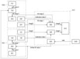
도 1 및 도 2를 참조하면, 본 발명의 기술적 사상에 따른 이미지 처리 시스템은, 제1 카메라 모듈(1021), 제2 카메라 모듈(1022), 이미지 처리 장치(1011) 및 입출력 센서(1030)를 포함할 수 있다.1 and 2 , an image processing system according to the technical idea of the present invention includes a
제1 카메라 모듈(1021)은, 제1 이미지 센서(101), 제1 저장 장치(102), 제1 이미지 안정 장치(image stabilizer)(103), 제1 틸트 센서(301) 및 제1 이미지 안정 장치 컨트롤러(303)를 포함할 수 있다. 제2 카메라 모듈(1022)은, 제2 이미지 센서(201), 제2 저장 장치(202)를 포함할 수 있다. 제1 카메라 모듈(1021)과 제2 카메라 모듈(1022)의 초점 거리는 서로 다를 수 있다. 예를 들어, 제1 카메라 모듈(1021)의 초점 거리는, 제2 카메라 모듈(1022)의 초점 거리보다 길 수 있다.The
제1 카메라 모듈(1021)과 제2 카메라 모듈(1022)은 서로 이격되어 배치될 수 있다.The
제1 이미지 센서(101)와 제2 이미지 센서(202)는 피사체에 대한 각각의 이미지를 획득할 수 있다. 몇몇 실시예에서, 제1 이미지 센서(101)는 좌영상을 획득하고, 제2 이미지 센서(202)는 우영상을 획득할 수 있다. 그러나 본 발명이 이에 제한되는 것은 아니다. 예를 들어, 제1 이미지 센서(101)는 우영상을 획득하고, 제2 이미지 센서(202)는 좌영상을 획득할 수도 있음은 물론이다.The
제1 저장 장치(102)에는, 제1 카메라 모듈(1021)에 대한 제1 캘리브레이션 데이터(calibration data 1)가 저장될 수 있다. 제1 캘리브레이션 데이터(calibration data 1)는, 예를 들어, 제1 카메라 모듈의 회전(rotation) 정도, 초점 거리, 및 광축에 대한 정보 중 적어도 어느 하나를 포함할 수 있다.The
제2 저장 장치(202)에는, 제2 카메라 모듈(1022)에 대한 제2 캘리브레이션 데이터(calibration data 2)가 저장될 수 있다. 제2 캘리브레이션 데이터(calibration data 2)는, 예를 들어, 제2 카메라 모듈의 회전(rotation) 정도, 초점 거리, 및 광축에 대한 정보 중 적어도 어느 하나를 포함할 수 있다.Second calibration data (calibration data 2) for the
제1 이미지 안정 장치(103)는 제1 카메라 모듈(1021) 내에 배치될 수 있다. 제1 이미지 안정 장치(103)는 제1 틸트 범위(tilt range 1)를 기초로 제1 이미지 센서(101)로부터 획득한 이미지를 보정할 수 있다. 몇몇 실시예에서, 제1 이미지 안정 장치(103)는 제1 카메라 모듈(1021)의 광축 정보를 이용하여, 제1 이미지 센서(101)로부터 획득한 이미지를 보정할 수 있다. 몇몇 실시예에서, 제1 이미지 안정 장치(103)는, 예를 들어, 제1 카메라 모듈(1021)에 대한 자이로(gyro) 정보를 이용하여, 제1 이미지 센서(101)로부터 획득한 이미지를 보정할 수 있다. 몇몇 실시예에서, 제1 이미지 안정 장치(103)는, 예를 들어, EIS(Electric Image Stabilizer)와 OIS(Optical Image Stabilizer) 중 어느 하나일 수 있다.The
제1 틸트 센서(301)는, 제1 카메라 모듈(1021)의 틸트 정도를 센싱하여 제1 틸트 값(tilt value 1)을 생성할 수 있다. 다시 말해서, 제1 틸트 값(tilt value 1)은, 제1 카메라 모듈(1021)의 틸트 정도를 나타낼 수 있다. 제1 틸트 센서(301)에 의해 센싱된 제1 틸트 값(tilt value 1)은 제1 이미지 안정 장치 컨트롤러(303)에 제공될 수 있다.The
제1 이미지 안정 장치 컨트롤러(303)는, 제1 틸트 센서(301)로부터 제1 틸트 값(tilt value 1)을 제공받고, 제1 틸트 범위 제어부(tilt range control unit)(620)로부터 제1 틸트 제한 값(limited tilt value 1)을 제공 받을 수 있다. 제1 틸트 제한 값(limited tilt value 1)에 대한 자세한 사항은 후술한다. 제1 이미지 안정 장치 컨트롤러(303)는 제1 틸트 값(tilt value 1)과 제1 틸트 제한 값(limited tilt value 1)을 기초로, 제1 틸트 범위(tilt range 1)를 생성할 수 있다. 예를 들어, 제1 틸트 범위(tilt range 1)는, 제1 틸트 값(tilt value 1)의 범위와 제1 틸트 제한 값(limited tilt value 1)의 범위가 중첩되는 범위일 수 있다.The first
도면에서, 제1 틸트 센서(301)와 제1 이미지 안정 장치 컨트롤러(303)가 제1 카메라 모듈(1021) 내에 배치되는 것으로 도시되었으나, 본 발명이 이에 제한되는 것은 아니다. 예를 들어, 제1 틸트 센서(301)와 제1 이미지 안정 장치 컨트롤러(303) 중 적어도 어느 하나는, 제1 카메라 모듈(1021)과 분리되어 배치될 수 있음은 물론이다.In the drawings, the
제1 카메라 모듈(1021) 및 제2 카메라 모듈(1022) 각각은 제1 이미지(image 1) 및 제2 이미지(image 2) 각각을 이미지 처리 장치(1011)에 제공할 수 있다.Each of the
몇몇 실시예에서, 제1 이미지(image 1)는 제1 틸트 범위(tilt range 1)를 기초로, 제1 이미지 센서(101)로부터 얻은 이미지가 보정된 것일 수 있다. 이는, 제1 카메라 모듈(1021)이 제1 이미지 안정 장치(103)를 포함하고 있기 때문이다. 반면, 제2 이미지(image 2)는 몇몇 실시예에서, 제2 카메라 모듈(1022)의 틸트 정도를 기초로 보정된 이미지가 아닐 수 있다. 즉, 제2 카메라 모듈(1022)은 이미지 안정 장치를 포함하고 있지 않을 수 있다.In some embodiments, the first image (image 1) may be a corrected image obtained from the
도면에서, 제1 이미지(image 1)는, 제1 이미지 센서(101)로부터 이미지 처리 장치(1011)로 직접 전달되는 것으로 도시되었으나, 본 발명이 이에 제한되는 것은 아니다. 예를 들어, 제1 이미지(image 1)는, 다른 유닛(unit)을 통과하여 이미지 처리 장치(1011)에 제공될 수 있음은 물론이다. 예를 들어, 제1 이미지(image 1)는 아날로그 디지털 컨버터를 통과하여 이미지 처리 장치(1011)로 제공될 수 있다. 이와 유사하게, 제2 이미지(image 2)도 다른 유닛, 예를 들어, 아날로그 디지털 컨버터를 통과하여 이미지 처리 장치(1011)로 제공될 수 있다.In the drawings, the first image (image 1) is shown as being directly transferred from the
이미지 처리 장치(1011)는 제1 이미지 왜곡 보정 유닛(400), 제2 이미지 왜곡 보정 유닛(500), 이미지 프로세싱 유닛(610) 및 제1 틸트 범위 제어부(620)을 포함할 수 있다. 이미지 처리 장치(1011)는 몇몇 실시예에서, 어플리케이션 프로세서의 일부일 수 있다.The
제1 이미지 왜곡 보정 유닛(400)은, 제1 카메라 모듈(1021)로부터 제1 이미지(image 1)와 제1 캘리브레이션 데이터(calibration data 1)를 제공받을 수 있다. 몇몇 실시예에서, 제1 이미지 왜곡 보정 유닛(400)에 제공되는 제1 이미지(image 1)는, 제1 카메라 모듈(1021)과 제1 이미지 왜곡 보정 유닛(400) 사이에 배치될 수 있는 이미지 신호처리 프로세서를 통과한 이미지일 수 있다. 또한, 제1 이미지 왜곡 보정 유닛(400)은, 제1 이미지(image 1)와 제1 캘리브레이션 데이터(calibration data 1) 이외에, 필요에 따라 다른 데이터를 제공받아, 제1 이미지(image 1)에 대한 보정을 수행할 수 있음은 물론이다.The first image
제1 이미지 왜곡 보정 유닛(400)은, 제1 캘리브레이션 데이터(calibration data 1)를 기초로, 제1 이미지(image 1)에 대한 보정을 수행할 수 있다. 예를 들어, 제1 이미지 왜곡 보정 유닛(400)은, 제1 이미지(image 1)에 대한 캘리브레이션(calibration) 작업과 제1 이미지(image 1)에 대한 영상 정합(rectification) 작업 중 적어도 어느 하나를 수행할 수 있다.The first image
제1 틸트 범위 제어부(620)는, 입출력 센서(1030)로부터 입력받은 데이터(data)에 기초하여, 제1 틸트 제한 값(limited tilt value 1)을 출력할 수 있다. 입출력 센서(1030)로부터 입력받은 데이터(data)는, 예를 들어, 줌 비(zoom ratio), 조도 값(illumination value) 등, 사용자가 직접 설정한 값이나, 사용자가 입출력 센서(1030)를 통해 조정할 수 있는 값에 대한 정보를 포함할 수 있다.The first
제1 틸트 제한 값(limited tilt value 1)은, 제1 틸트 값(tilt value 1)의 범위를 제한하는 값일 수 있다. 예를 들어, 제1 틸트 범위 제어부(620)는, 제1 카메라 모듈(1021)과 제2 카메라 모듈(1022)의 초점 길이가 다른 경우, 사용자가 설정한 데이터(data) 중 하나인 줌 비에 기초하여, 제1 틸트 제한 값(limited tilt value 1)을 결정할 수 있다. 예를 들어, 줌 비를 달리 하면서, 제1 카메라 모듈(1021)에서 제2 카메라 모듈(1022)로 자연스럽게 전환되도록 하기 위한 제1 틸트 제한 값(limited tilt value 1)을 실험적으로 얻을 수 있다.The first tilt limit value (limited tilt value 1) may be a value limiting the range of the first tilt value (tilt value 1). For example, when the focal lengths of the
또는, 예를 들어, 제1 카메라 모듈(1021)과 제2 카메라 모듈(1022) 각각이 베이어(bayer) 카메라와 모노크롬(monochrome) 카메라인 경우, 제1 틸트 범위 제어부(620)는, 사용자가 설정한 데이터(data) 중 하나인 저조도 환경에서의 노출 시간 등에 기초하여, 제1 틸트 제한 값(limited tilt value 1)을 결정할 수 있다. 예를 들어, 노출 시간을 달리 하면서, 이미지 프로세싱 유닛(610)의 결과 이미지의 신호대잡음비(SNR) 등의 향상 효과를 고려하여, 제1 틸트 제한 값(limited tilt value 1)을 실험적으로 얻을 수 있다.Alternatively, for example, when the
제1 이미지 안정 장치(103)에 제공되는 제1 틸트 범위(tilt range 1)는, 제1 틸트 제한 값(limited tilt value 1)의 범위와 제1 틸트 값(tilt value 1)의 범위가 중첩되는 범위일 수 있다.The first tilt range (tilt range 1) provided to the first
본 발명의 기술적 사상에 따른 이미지 장치는, 제1 틸트 제한 값(limited tilt value 1)을 이용하여 생성된 제1 틸트 범위(tilt range 1)를 이용하여 이미지에 대한 보정을 수행함으로써, 저조도 상황에서 야기되는 모션 블러(motion blur)의 차이를 최소화하거나, 초점 길이가 다른 카메라 모듈 사이에서의 자연스러운 전환을 유도할 수 있다.An image device according to a technical concept of the present invention performs correction on an image using a first tilt range (tilt range 1) generated using a first limited tilt value (limited tilt value 1), so that in a low light situation A difference in induced motion blur may be minimized or a natural transition between camera modules having different focal lengths may be induced.
제2 이미지 왜곡 보정 유닛(500)은, 제2 카메라 모듈(1022)로부터 제2 이미지(image 2)와 제2 캘리브레이션 데이터(calibration data 2)를 제공받을 수 있다. 또한, 몇몇 실시예에서, 제2 이미지 왜곡 보정 유닛(500)은, 제1 카메라 모듈(1021)로부터 제1 틸트 범위(tilt range 1)를 제공받을 수 있다. 몇몇 실시예에서, 제2 이미지 왜곡 보정 유닛(500)에 제공되는 제2 이미지(image 2)는, 제2 카메라 모듈(1022)과 제2 이미지 왜곡 보정 유닛(500) 사이에 배치될 수 있는 이미지 신호처리 프로세서를 통과한 이미지일 수 있다. 또한, 제2 이미지 왜곡 보정 유닛(500)은, 필요에 따라, 제2 이미지(image 2), 제2 캘리브레이션 데이터(calibration data 2) 및 제1 틸트 범위(tilt range 1) 이외에, 다른 데이터들을 제공받아, 제2 이미지(image 2)에 대한 보정을 수행할 수 있음은 물론이다.The second image
제2 이미지 왜곡 보정 유닛(500)은, 제2 캘리브레이션 데이터(calibration data 2)와 제1 틸트 범위(tilt range 1)를 기초로, 제2 이미지(image 2)에 대한 보정을 수행할 수 있다. 예를 들어, 제2 이미지 왜곡 보정 유닛(500)은, 제2 이미지(image 2)에 대한 캘리브레이션 작업, 제2 이미지(image 2)에 대한 영상 정합 작업 및 제2 이미지의 블러 효과를 제거하는 디블러(de-blur) 작업 중 적어도 어느 하나를 수행할 수 있다.The second image
본 발명의 기술적 사상에 따른 이미지 처리 장치는, 제2 이미지 왜곡 보정 유닛(500)이 제1 틸트 범위(tilt range 1)를 기초로, 제2 이미지(image 2)에 대한 보정을 수행함으로써, 모션 블러나 정렬 불일치(misalignment) 등이 최소화된 보정된 이미지를 생성할 수 있다. 즉, 이미지 안정 장치(image stabilizer)가 포함되지 않은 카메라 모듈로부터 생성된 이미지를, 이미지 안정 장치를 포함하는 카메라 모듈에서 이용한 틸트 범위(예를 들어, 제1 틸트 범위(tilt range 1))를 이용하여 보정함으로써, 이미지 안정 장치가 포함되어 있지 않은 카메라 모듈에서도, 이미지 안정 장치에 따른 보정효과를 야기시킬 수 있다.In the image processing apparatus according to the technical idea of the present invention, the second image
이미지 프로세싱 유닛(610)은, 제1 이미지 왜곡 보정 유닛(400)으로부터 보정된 제1 이미지(image 1')와, 제2 이미지 왜곡 보정 유닛(500)으로부터 보정된 제2 이미지(image 2')를 제공 받을 수 있다. 이미지 프로세싱 유닛(610)은, 보정된 제1 및 제2 이미지(image 1', image 2')에 대한 이미지 프로세싱을 수행할 수 있다.The
이미지 처리 장치(1011)는, 예를 들어, 어플리케이션 프로세서(1010)의 일부일 수 있다. 또한, 도면에서 일정 유닛(unit)들만 도시하였으나, 이는 설명의 편의를 위한 것일 뿐, 본 발명이 이에 제한되는 것은 아니다. 필요에 따라, 이미지 처리 장치(1011)는, 다양한 유닛들을 포함할 수 있음은 물론이다.The
이하에서, 도 1 및 도 3을 참조하여 본 발명의 몇몇 실시예들에 따른 이미지 처리 장치에 대해 설명한다. 설명의 명확성을 위해 앞서 설명한 것과 중복되는 것은 생략한다.Hereinafter, an image processing apparatus according to some embodiments of the present invention will be described with reference to FIGS. 1 and 3 . For clarity of explanation, duplicates with those described above are omitted.
도 3은 본 발명의 몇몇 실시예들에 따른 이미지 처리 장치의 블록도이다.3 is a block diagram of an image processing device according to some embodiments of the present invention.
도 1 및 도 3을 참조하면, 본 발명의 몇몇 실시예들에 따른 이미지 처리 장치(1011)는, 캘리브레이션 데이터 재생성부(calibration data regeneration unit)(520) 및 보정부(rectification unit)(530)를 포함할 수 있다.1 and 3 , an
캘리브레이션 데이터 재생성부(520)는, 제2 카메라 모듈(1022)로부터 제2 이미지(image 2)와 제2 캘리브레이션 데이터(calibration data 2)를 제공받고, 제1 카메라 모듈(1021)로부터 제1 틸트 범위(tilt range 1)를 제공받을 수 있다.The calibration
제2 이미지(image 2)는, 제2 카메라 모듈(1022)의 틸트 정도를 기초로 보정된 이미지가 아닐 수 있다. 몇몇 실시예에서, 제2 카메라 모듈(1022)은, 이미지 안정 장치를 포함하고 있지 않을 수 있다.The second image (image 2) may not be an image corrected based on the degree of tilt of the
제1 틸트 범위(tilt range 1)는, 제1 카메라 모듈(1021)의 제1 틸트 값(tilt value 1)의 범위와, 제1 틸트 범위 제어부(620)로부터 생성된 제1 틸트 제한 값(limited tilt value 1)의 범위가 중첩되는 범위일 수 있다. 제1 틸트 범위(tilt range 1)는, 예를 들어, 제1 카메라 모듈(1021)로부터 제공받을 수 있다.The first tilt range (tilt range 1) includes the range of the first tilt value (tilt value 1) of the
캘리브레이션 데이터 재생성부(520)는, 제1 틸트 범위(tilt range 1)를 기초로, 제2 캘리브레이션 데이터(calibration data 2)를 수정하여, 제3 캘리브레이션 데이터(data)를 생성할 수 있다. 다시 말해서, 제3 캘리브레이션 데이터(data)는, 제2 카메라 모듈(1022)에 대한 제2 캘리브레이션 데이터(calibration data 2)에, 제1 카메라 모듈(1021)에 대한 제1 틸트 범위(tilt range 1)를 반영한 것일 수 있다.The
보정부(530)는, 캘리브레이션 데이터 재생성부(520)로부터 제공받은 제3 캘리브레이션 데이터(data)를 기초로, 제2 이미지(image 2)에 대한 보정을 수행할 수 있다. 예를 들어, 보정부(530)는, 제2 이미지(image 2)에 대한 캘리브레이션 작업과 제2 이미지(image 2)에 대한 영상 정합 작업 중 적어도 어느 하나를 수행할 수 있다.The
보정부(530)로부터 생성된 보정된 제2 이미지(image 2')는, 제1 카메라 모듈(1021)의 제1 틸트 값(tilt value 1)이 반영되어 보정 작업이 수행된 이미지일 수 있다. 다시 말해서, 보정된 제2 이미지(image 2')에는, 제1 카메라 모듈(1021)의 틸트 정도에 대한 정보가 반영될 수 있다.The corrected second image (
즉, 본 발명의 기술적 사상에 따른 이미지 처리 장치는, 캘리브레이션 데이터 재생성부(520)가 제1 틸트 범위(tilt range 1)를 제공받아 수정된 제2 캘리브레이션 데이터(즉, 제3 캘리브레이션 데이터(data))를 생성하고, 수정된 제2 캘리브레이션 데이터(즉, 제3 캘리브레이션 데이터(data))를 이용하여 제2 이미지(image 2)를 보정함으로써, 이미지 안정 장치가 포함되어 있지 않은 카메라 모듈에서 생성된 이미지(예를 들어, 제2 이미지(image 2))에 대해, 이미지 안정 장치에 따른 보정효과를 야기시킬 수 있다.That is, in the image processing device according to the technical idea of the present invention, the calibration
이하에서, 도 1 및 도 4를 참조하여 본 발명의 몇몇 실시예들에 따른 이미지 처리 장치에 대해 설명한다. 설명의 명확성을 위해 앞서 설명한 것과 중복되는 것은 생략한다.Hereinafter, an image processing apparatus according to some embodiments of the present invention will be described with reference to FIGS. 1 and 4 . For clarity of explanation, duplicates with those described above are omitted.
도 4은 본 발명의 몇몇 실시예들에 따른 이미지 처리 장치의 블록도이다.4 is a block diagram of an image processing device according to some embodiments of the present invention.
도 1 및 도 4를 참조하면, 본 발명의 몇몇 실시예들에 따른 이미지 처리 장치(1011)의 제2 이미지 왜곡 보정 유닛(500)은, 제2 캘리브레이션 데이터(calibration data 2), 제1 틸트 범위(tilt range 1) 및 제2 틸트 범위(tilt range 2)를 기초로, 제2 이미지(image 2)에 대한 보정을 수행할 수 있다.Referring to FIGS. 1 and 4 , the second image
제2 틸트 범위(tilt range 2)는, 예를 들어, 제2 카메라 모듈(1022)의 틸트 정도를 나타내는 제2 틸트 값(tilt value 2)의 범위와, 제1 틸트 제한 값(limited tilt value 1)의 범위가 중첩되는 범위일 수 있다. 또한, 제2 이미지(image 2)는, 제2 카메라 모듈(1022)에 대한 제2 틸트 범위(tilt range 2)를 기초로, 제2 이미지 센서(202)로부터 얻은 이미지가 보정된 것일 수 있다.The second tilt range (tilt range 2) may include, for example, a range of a second tilt value (tilt value 2) representing the degree of tilt of the
구체적으로, 제2 카메라 모듈(1022)은, 예를 들어, 제2 틸트 센서(701), 제2 이미지 안정 장치 컨트롤러(703) 및 제2 이미지 안정 장치(203)를 포함할 수 있다.Specifically, the
제2 이미지 안정 장치(203)는 제2 카메라 모듈(1022) 내에 배치될 수 있다. 제2 이미지 안정 장치(203)는, 제2 틸트 범위(tilt range 2)를 기초로, 제2 이미지 센서(202)로부터 획득한 이미지를 보정할 수 있다. 제2 이미지 안정 장치(203)는, 예를 들어, 제1 이미지 안정 장치(103)와 동종의 것이거나, 이종의 것일 수 있다.The
제2 틸트 센서(701)는, 제2 카메라 모듈(1022)의 틸트 정도를 센싱하여 제2 틸트 값(tilt value 2)을 생성할 수 있다. 다시 말해서, 제2 틸트 값(tilt value 2)은, 제2 카메라 모듈(1022)의 틸트 정도를 나타낼 수 있다. 제2 틸트 센서(701)에 의해 센싱된 제2 틸트 값(tilt value 2)은, 제2 이미지 안정 장치 컨트롤러(703)에 제공될 수 있다.The
제2 이미지 안정 장치 컨트롤러(703)는, 제2 틸트 센서(701)로부터 제2 틸트 값(tilt value 2)을 제공받고, 제1 틸트 범위 제어부(620)로부터 제1 틸트 제한 값(limited tilt value 1)을 제공받을 수 있다. 제2 이미지 안정 장치 컨트롤러(703)는, 제2 틸트 값(tilt value 2)과 제1 틸트 제한 값(limited tilt value 1)을 기초로, 제2 틸트 범위(tilt range 2)를 생성할 수 있다.The second
도면에서, 제2 틸트 센서(701)와 제2 이미지 안정 장치 컨트롤러(703)가 제2 카메라 모듈(1022) 내에 배치되는 것으로 도시되었으나, 본 발명이 이에 제한되는 것은 아니다. 예를 들어, 제2 틸트 센서(701)와 제2 이미지 안정 장치 컨트롤러(703) 중 적어도 어느 하나는, 제2 카메라 모듈(1022)과 분리되어 배치될 수 있음은 물론이다.In the drawings, the
제2 이미지 왜곡 보정 유닛(500)은, 제2 카메라 모듈(1022)로부터 제2 이미지(image 2), 제2 캘리브레이션 데이터(calibration data 2) 및 제2 틸트 범위(tilt range 2)를 제공받고, 제1 카메라 모듈(1021)로부터 제1 틸트 범위(tilt range 1)를 제공받을 수 있다. 제2 이미지 왜곡 보정 유닛(500)은, 제2 캘리브레이션 데이터(calibration data 2), 제1 틸트 범위(tilt range 1) 및 제2 틸트 범위(tilt range 2)를 기초로, 제2 이미지(image 2)에 대한 보정을 수행할 수 있다.The second image
본 발명의 기술적 사상에 따른 이미지 처리 장치는, 제2 이미지 왜곡 보정 유닛(500)이 제1 틸트 범위(tilt range 1) 및 제2 틸트 범위(tilt range 2)를 기초로 제2 이미지(image 2)에 대한 보정을 수행함으로써, 제1 카메라 모듈(1021)과 제2 카메라 모듈(1022)에 이종의 이미지 안정 장치가 포함되었을 때 야기되는 제1 이미지(image 1)와 제2 이미지(image 2)간의 차이를 고려하여 모션 블러나 정렬 불일치 등이 최소화된 보정된 이미지를 생성할 수 있다. 또한, 제1 카메라 모듈(1021)과 제2 카메라 모듈(1022)에 동종의 이미지 안정 장치가 포함된 경우에도, 제1 틸트 제한 값(limited tilt value 1)을 이용하여 최적의 제1 틸트 범위(tilt range 1) 및 제2 틸트 범위(tilt range 2)를 생성함으로써, 제1 이미지(image 1)와 제2 이미지(image 2)간의 차이에 따른 이미지의 왜곡을 최소화시킬 수 있다.In the image processing apparatus according to the technical idea of the present invention, the second image
이하에서, 도 1 및 도 5를 참조하여 본 발명의 몇몇 실시예들에 따른 이미지 처리 장치에 대해 설명한다. 설명의 명확성을 위해 앞서 설명한 것과 중복되는 것은 생략한다.Hereinafter, an image processing apparatus according to some embodiments of the present invention will be described with reference to FIGS. 1 and 5 . For clarity of explanation, duplicates with those described above are omitted.
도 5는 본 발명의 몇몇 실시예들에 따른 이미지 처리 장치의 블록도이다.5 is a block diagram of an image processing device according to some embodiments of the present invention.
도 1 및 도 5를 참조하면, 본 발명의 몇몇 실시예들에 따른 이미지 처리 장치(1011)의 제2 틸트 범위(tilt range 2)는, 제2 틸트 값(tilt value 2)의 범위와 제2 틸트 제한 값(limited tilt value 2)의 범위가 중첩되는 범위일 수 있다.Referring to FIGS. 1 and 5 , a second tilt range (tilt range 2) of the
구체적으로, 이미지 처리 장치(1011)는, 제2 틸트 범위 제어부(630)를 더 포함할 수 있다. 제2 틸트 범위 제어부(630)는, 입출력 센서(1030)로부터 입력받은 데이터(data)에 기초하여, 제2 틸트 제한 값(limited tilt value 2)을 출력할 수 있다. 제2 틸트 제한 값(limited tilt value 2)은, 제2 틸트 값(tilt value 2)의 범위를 제한하는 값일 수 있다. 제2 틸트 제한 값(limited tilt value 2)은, 제1 틸트 제한 값(limited tilt value 1)을 얻는 방법과 실질적으로 유사한 방식으로 얻어질 수 있다. 제2 틸트 제한 값(limited tilt value 2)은, 제1 틸트 제한 값(limited tilt value 1)과 동일한 범위를 갖거나, 제1 틸트 제한 값(limited tilt value 1)의 범위와 중첩되지 않는 범위를 가질 수 있다. 또는, 제2 틸트 제한 값(limited tilt value 2)의 범위는, 제1 틸트 제한 값(limited tilt value 1)의 범위와 일부 중첩될 수도 있다.Specifically, the
제2 이미지 왜곡 보정 유닛(500)은, 제2 카메라 모듈(1022)로부터 제2 이미지(image 2), 제2 캘리브레이션 데이터(calibration data 2) 및 제2 틸트 범위(tilt range 2)를 제공받고, 제1 카메라 모듈(1021)로부터 제1 틸트 범위(tilt range 1)를 제공받아, 제2 이미지(image 2)에 대한 보정을 수행할 수 있다.The second image
본 발명의 기술적 사상에 따른 이미지 처리 장치(1011)는, 각 카메라 모듈(1021, 1022)에 대한 틸트 제한 값을 각각 생성함으로써, 최적의 제1 틸트 범위(tilt range 1)와 제2 틸트 범위(tilt range 2)를 생성할 수 있다. 이로써, 동종 또는 이종의 이미지 안정 장치를 포함하는 제1 카메라 모듈(1021)과 제2 카메라 모듈(1022)로부터 생성된 제1 이미지(image 1) 및 제2 이미지(image 2) 간의 차이에 따른 이미지의 왜곡은, 최소화될 수 있다.The
이하에서, 도 1 및 도 6을 참조하여 본 발명의 몇몇 실시예들에 따른 이미지 처리 장치에 대해 설명한다. 설명의 명확성을 위해 앞서 설명한 것과 중복되는 것은 생략한다.Hereinafter, an image processing apparatus according to some embodiments of the present invention will be described with reference to FIGS. 1 and 6 . For clarity of explanation, duplicates with those described above are omitted.
도 6은 본 발명의 몇몇 실시예들에 따른 이미지 처리 장치의 블록도이다.6 is a block diagram of an image processing device according to some embodiments of the present invention.
도 1 및 도 6을 참조하면, 본 발명의 몇몇 실시예들에 따른 이미지 처리 장치(1011)는, 캘리브레이션 데이터 재생성부(520) 및 보정부(530)를 포함할 수 있다.Referring to FIGS. 1 and 6 , an
캘리브레이션 데이터 재생성부(520)는, 제2 카메라 모듈(1022)로부터 제2 이미지(image 2), 제2 캘리브레이션 데이터(calibration data 2) 및 제2 틸트 범위(tilt range 2)를 제공받고, 제1 카메라 모듈(1021)로부터 제1 틸트 범위(tilt range 1)를 제공받을 수 있다.The calibration
도면에서, 제2 틸트 범위(tilt range 2)는, 제2 틸트 제한 값(limited tilt value 2)을 기초로 생성된 범위인 것으로 도시하였으나, 본 발명이 이에 제한되는 것은 아니다. 예를 들어, 제2 틸트 범위(tilt range 2)는, 제1 틸트 제한 값(limited tilt value 1)을 기초로 생성된 범위일 수도 있다.In the figure, the second tilt range (tilt range 2) is shown as being a range generated based on the second limited tilt value (limited tilt value 2), but the present invention is not limited thereto. For example, the second tilt range (tilt range 2) may be a range generated based on the first limited tilt value (limited tilt value 1).
캘리브레이션 데이터 재생성부(520)는, 제1 틸트 범위(tilt range 1)와 제2 틸트 범위(tilt range 2)를 기초로, 제2 캘리브레이션 데이터(calibration data 2)를 수정하여, 제3 캘리브레이션 데이터(data)를 생성할 수 있다. 다시 말해서, 제3 캘리브레이션 데이터(data)는, 제2 카메라 모듈(1022)에 대한 제2 캘리브레이션 데이터(calibration data 2)에, 제1 카메라 모듈(1021)에 대한 제1 틸트 범위(tilt range 1)와 제2 카메라 모듈(1022)에 대한 제2 틸트 범위(tilt range 2)를 반영한 것일 수 있다.The
보정부(530)로부터 생성된 보정된 제2 이미지(image 2')는, 제1 카메라 모듈(1021)의 제1 틸트 값(tilt value 1)과 제2 카메라 모듈(1022)의 제2 틸트 값(tilt value 2)이 반영되어, 보정 작업이 수행된 이미지일 수 있다. 다시 말해서, 보정된 제2 이미지(image 2')에는, 제1 카메라 모듈(1021)의 틸트 정도에 대한 정보와, 제2 카메라 모듈(1022)의 틸트 정도에 대한 정보를 모두 반영될 수 있다.The corrected second image (
본 발명의 기술적 사상에 따른 이미지 처리 장치는, 캘리브레이션 데이터 재생성부(520)가 제1 틸트 범위(tilt range 1)와 제2 틸트 범위(tilt range 2)를 기초로 수정된 제2 캘리브레이션 데이터(즉, 제3 캘리브레이션 데이터(data))를 생성하고, 이를 이용하여 제2 이미지(image 2)를 보정함으로써, 동종 또는 이종의 이미지 안정 장치가 포함된 카메라 모듈로부터 생성된 이미지들간의 차이를 고려하여 왜곡을 최소화시킨 이미지를 생성할 수 있다.In the image processing apparatus according to the technical idea of the present invention, the
이상 첨부된 도면을 참조하여 본 발명의 실시예들을 설명하였으나, 본 발명은 상기 실시예들에 한정되는 것이 아니라 서로 다른 다양한 형태로 제조될 수 있으며, 본 발명이 속하는 기술분야에서 통상의 지식을 가진 자는 본 발명의 기술적 사상이나 필수적인 특징을 변경하지 않고서 다른 구체적인 형태로 실시될 수 있다는 것을 이해할 수 있을 것이다. 그러므로 이상에서 기술한 실시예들은 모든 면에서 예시적인 것이며 한정적이 아닌 것으로 이해해야만 한다.Although the embodiments of the present invention have been described with reference to the accompanying drawings, the present invention is not limited to the above embodiments and can be manufactured in a variety of different forms, and those skilled in the art in the art to which the present invention belongs A person will understand that the present invention may be embodied in other specific forms without changing the technical spirit or essential features. Therefore, the embodiments described above should be understood as illustrative in all respects and not limiting.
1011: 이미지 안정 장치500: 제2 이미지 왜곡 보정 유닛
620: 제1 틸트 범위 제어부1011: image stabilizer 500: second image distortion correction unit
620: first tilt range controller
Claims (10)
Translated fromKorean제2 카메라 모듈로부터 제2 이미지와 제2 캘리브레이션 데이터를 제공받고, 상기 제1 카메라 모듈로부터 제1 틸트 범위를 제공받아, 상기 제2 캘리브레이션 데이터와 상기 제1 틸트 범위를 기초로 상기 제2 이미지에 대한 보정을 수행하는 제2 이미지 왜곡 보정 유닛; 및
상기 제1 및 제2 이미지 왜곡 보정 유닛으로부터 보정된 제1 및 제2 이미지를 제공받고, 이미지 프로세싱을 수행하는 이미지 프로세싱 유닛(Image Processing Unit)을 포함하고,
상기 제1 이미지는, 상기 제1 틸트 범위를 기초로, 상기 제1 카메라 모듈의 이미지 센서로부터 얻은 이미지가 보정된 것인 이미지 처리 장치.a first image distortion correction unit receiving a first image and first calibration data from a first camera module and correcting the first image based on the first calibration data;
A second image and second calibration data are provided from a second camera module, a first tilt range is provided from the first camera module, and the second image is provided based on the second calibration data and the first tilt range. a second image distortion correction unit that performs correction for ; and
An image processing unit receiving corrected first and second images from the first and second image distortion correction units and performing image processing,
The first image is an image obtained by correcting an image obtained from an image sensor of the first camera module based on the first tilt range.
상기 제1 틸트 범위는,
상기 제1 카메라 모듈의 틸트 정도를 나타내는 제1 틸트 값의 범위와, 입출력 센서로부터 입력 받은 데이터에 기초한 제1 틸트 제한 값의 범위가 중첩되는 범위인 이미지 처리 장치.According to claim 1,
The first tilt range,
An image processing device in which a range of a first tilt value indicating a degree of tilt of the first camera module overlaps a range of a first tilt limit value based on data input from an input/output sensor.
상기 제2 이미지 왜곡 보정 유닛은,
상기 제1 틸트 범위를 기초로 상기 제2 캘리브레이션 데이터를 수정하여 제3 캘리브레이션 데이터를 생성하는 캘리브레이션 데이터 재생성부(calibration data regeneration unit); 및
상기 제3 캘리브레이션 데이터를 입력 받아, 상기 제2 이미지에 대한 영상 정합(rectification)을 수행하여, 상기 보정된 제2 이미지를 출력하는 보정부(rectification unit)를 포함하는 이미지 처리 장치.According to claim 1,
The second image distortion correction unit,
a calibration data regeneration unit generating third calibration data by modifying the second calibration data based on the first tilt range; and
and a rectification unit configured to receive the third calibration data, perform image rectification on the second image, and output the corrected second image.
상기 제2 이미지는, 상기 제2 카메라 모듈에 대한 제2 틸트 범위를 기초로, 상기 제2 카메라 모듈의 이미지 센서로부터 얻은 이미지가 보정된 것이고,
상기 제2 이미지 왜곡 보정 유닛은, 상기 제2 캘리브레이션 데이터, 상기 제1 틸트 범위 및 상기 제2 틸트 범위를 기초로, 상기 제2 이미지에 대한 보정을 수행하는 이미지 처리 장치.According to claim 1,
The second image is a corrected image obtained from an image sensor of the second camera module based on a second tilt range for the second camera module,
wherein the second image distortion correction unit corrects the second image based on the second calibration data, the first tilt range, and the second tilt range.
상기 제1 틸트 범위는,
상기 제1 카메라 모듈의 틸트 정도를 나타내는 제1 틸트 값의 범위와, 입출력 센서로부터 입력 받은 데이터에 기초한 제1 틸트 제한 값의 범위가 중첩되는 범위이고,
상기 제2 틸트 범위는,
상기 제2 카메라 모듈의 틸트 정도를 나타내는 제2 틸트 값의 범위와, 상기 데이터에 기초한 제2 틸트 제한 값의 범위가 중첩되는 범위인 이미지 처리 장치.According to claim 4,
The first tilt range,
A range in which a range of a first tilt value representing a degree of tilt of the first camera module overlaps a range of a first tilt limit value based on data input from an input/output sensor,
The second tilt range,
The image processing device of claim 1 , wherein a range of a second tilt value indicating a degree of tilt of the second camera module and a range of a second tilt limit value based on the data overlap.
상기 제1 틸트 범위는,
상기 제1 카메라 모듈의 틸트 정도를 나타내는 제1 틸트 값의 범위와, 입출력 센서로부터 입력 받은 데이터에 기초한 제1 틸트 제한 값의 범위가 중첩되는 범위이고,
상기 제2 틸트 범위는,
상기 제2 카메라 모듈의 틸트 정도를 나타내는 제2 틸트 값의 범위와, 상기 제1 틸트 제한 값의 범위가 중첩되는 범위인 이미지 처리 장치.According to claim 4,
The first tilt range,
A range in which a range of a first tilt value representing a degree of tilt of the first camera module overlaps a range of a first tilt limit value based on data input from an input/output sensor,
The second tilt range,
The image processing device of claim 1 , wherein a range of second tilt values indicating a degree of tilt of the second camera module and a range of the first tilt limit value overlap each other.
상기 제2 이미지 왜곡 보정 유닛은,
상기 제1 및 제2 틸트 범위를 기초로 상기 제1 캘리브레이션 데이터를 수정하여 제3 캘리브레이션 데이터를 생성하는 캘리브레이션 데이터 재생성부(calibration data regeneration unit); 및
상기 제3 캘리브레이션 데이터를 입력 받아, 상기 제2 이미지에 대한 영상 정합(rectification)을 수행하여, 상기 보정된 제2 이미지를 출력하는 보정부(rectification unit)를 포함하는 이미지 처리 장치.According to claim 4,
The second image distortion correction unit,
a calibration data regeneration unit generating third calibration data by modifying the first calibration data based on the first and second tilt ranges; and
and a rectification unit configured to receive the third calibration data, perform image rectification on the second image, and output the corrected second image.
제1 카메라 모듈로부터 제1 이미지와 제1 캘리브레이션 데이터를 제공받아, 상기 제1 캘리브레이션 데이터를 기초로 상기 제1 이미지에 대한 보정을 수행하는 제1 이미지 왜곡 보정 유닛(Image Distortion Correction Unit);
제2 카메라 모듈로부터 제2 이미지와 제2 캘리브레이션 데이터를 제공받아, 상기 제2 캘리브레이션 데이터를 기초로 상기 제2 이미지에 대한 보정을 수행하는 제2 이미지 왜곡 보정 유닛; 및
상기 제1 및 제2 이미지 왜곡 보정 유닛으로부터 보정된 제1 및 제2 이미지를 제공받고, 이미지 프로세싱을 수행하는 이미지 프로세싱 유닛(Image Processing Unit)을 포함하고,
상기 제1 이미지는, 상기 제1 카메라 모듈의 틸트 정도를 나타내는 제1 틸트 값의 범위와 상기 제1 틸트 제한 값의 범위가 중첩되는 범위인 제1 틸트 범위를 기초로 상기 제1 카메라 모듈의 이미지 센서로부터 얻은 이미지가 보정된 것인 이미지 처리 장치.a first tilt range control unit outputting a first tilt limit value based on data received from an input/output sensor;
a first image distortion correction unit receiving a first image and first calibration data from a first camera module and correcting the first image based on the first calibration data;
a second image distortion correction unit receiving a second image and second calibration data from a second camera module and correcting the second image based on the second calibration data; and
An image processing unit receiving corrected first and second images from the first and second image distortion correction units and performing image processing,
The first image is an image of the first camera module based on a first tilt range, which is a range in which a range of a first tilt value representing a degree of tilt of the first camera module and a range of the first tilt limit value overlap. An image processing device in which an image obtained from a sensor is calibrated.
상기 제2 이미지 왜곡 보정 유닛은, 상기 제1 틸트 범위를 더 입력 받아, 상기 제1 틸트 범위 및 상기 제2 캘리브레이션 데이터를 기초로 상기 제2 이미지에 대한 보정을 수행하는 이미지 처리 장치.According to claim 8,
The image processing apparatus of claim 1 , wherein the second image distortion correction unit further receives the first tilt range and corrects the second image based on the first tilt range and the second calibration data.
상기 제2 이미지 왜곡 보정 유닛은,
상기 제1 틸트 범위를 기초로 상기 제2 캘리브레이션 데이터를 수정하여 제3 캘리브레이션 데이터를 생성하는 캘리브레이션 데이터 재생성부(calibration data regeneration unit); 및
상기 제3 캘리브레이션 데이터를 입력 받아, 상기 제2 이미지에 대한 영상 정합(rectification)을 수행하여, 상기 보정된 제2 이미지를 출력하는 보정부(rectification unit)를 포함하는 이미지 처리 장치.According to claim 9,
The second image distortion correction unit,
a calibration data regeneration unit generating third calibration data by modifying the second calibration data based on the first tilt range; and
and a rectification unit configured to receive the third calibration data, perform image rectification on the second image, and output the corrected second image.
Priority Applications (2)
| Application Number | Priority Date | Filing Date | Title |
|---|---|---|---|
| KR1020160164255AKR102540236B1 (en) | 2016-12-05 | 2016-12-05 | Image processing decive and system |
| US15/826,013US10225474B2 (en) | 2016-12-05 | 2017-11-29 | Image processing device and system |
Applications Claiming Priority (1)
| Application Number | Priority Date | Filing Date | Title |
|---|---|---|---|
| KR1020160164255AKR102540236B1 (en) | 2016-12-05 | 2016-12-05 | Image processing decive and system |
Publications (2)
| Publication Number | Publication Date |
|---|---|
| KR20180064086A KR20180064086A (en) | 2018-06-14 |
| KR102540236B1true KR102540236B1 (en) | 2023-06-02 |
Family
ID=62243617
Family Applications (1)
| Application Number | Title | Priority Date | Filing Date |
|---|---|---|---|
| KR1020160164255AActiveKR102540236B1 (en) | 2016-12-05 | 2016-12-05 | Image processing decive and system |
Country Status (2)
| Country | Link |
|---|---|
| US (1) | US10225474B2 (en) |
| KR (1) | KR102540236B1 (en) |
Families Citing this family (5)
| Publication number | Priority date | Publication date | Assignee | Title |
|---|---|---|---|---|
| EP3840685B1 (en)* | 2018-08-24 | 2025-10-01 | Intuitive Surgical Operations, Inc. | Off-camera calibration parameters for an image capture device |
| US11336830B2 (en)* | 2019-01-03 | 2022-05-17 | Corephotonics Ltd. | Multi-aperture cameras with at least one two state zoom camera |
| US10970511B2 (en)* | 2019-06-26 | 2021-04-06 | Synaptics Incorporated | System and method for correcting distortions in a biometric image |
| WO2021035485A1 (en)* | 2019-08-26 | 2021-03-04 | Oppo广东移动通信有限公司 | Shooting anti-shake method and apparatus, terminal and storage medium |
| CN110708537B (en)* | 2019-09-30 | 2021-05-28 | 芯盟科技有限公司 | Image sensor performance testing method and device, storage medium |
Family Cites Families (23)
| Publication number | Priority date | Publication date | Assignee | Title |
|---|---|---|---|---|
| US20040201707A1 (en) | 1998-03-12 | 2004-10-14 | Kazuhiro Noguchi | Variable magnification lens having image stabilizing function |
| JP4191449B2 (en)* | 2002-09-19 | 2008-12-03 | 株式会社トプコン | Image calibration method, image calibration processing device, image calibration processing terminal |
| JP4095491B2 (en)* | 2003-05-19 | 2008-06-04 | 本田技研工業株式会社 | Distance measuring device, distance measuring method, and distance measuring program |
| JP4542011B2 (en) | 2005-09-27 | 2010-09-08 | 富士通株式会社 | Camera, image stabilization method, and image stabilization program |
| KR100819301B1 (en) | 2006-12-20 | 2008-04-03 | 삼성전자주식회사 | Image stabilization method and apparatus of a camera module for mobile devices |
| US8723969B2 (en) | 2007-03-20 | 2014-05-13 | Nvidia Corporation | Compensating for undesirable camera shakes during video capture |
| US9177368B2 (en) | 2007-12-17 | 2015-11-03 | Nvidia Corporation | Image distortion correction |
| JP2009151028A (en) | 2007-12-19 | 2009-07-09 | Sanyo Electric Co Ltd | Vibration correction control circuit and imaging apparatus equipped with the same |
| US8547440B2 (en) | 2010-01-29 | 2013-10-01 | Nokia Corporation | Image correction for image capturing with an optical image stabilizer |
| US9131155B1 (en) | 2010-04-07 | 2015-09-08 | Qualcomm Technologies, Inc. | Digital video stabilization for multi-view systems |
| CN102474573B (en)* | 2010-06-11 | 2016-03-16 | 松下电器(美国)知识产权公司 | Image processing apparatus and image processing method |
| US8463073B2 (en)* | 2010-11-29 | 2013-06-11 | Microsoft Corporation | Robust recovery of transform invariant low-rank textures |
| KR101862404B1 (en) | 2011-12-09 | 2018-05-29 | 엘지이노텍 주식회사 | Apparatus and method for eliminating noise of stereo image |
| EP2706408B1 (en) | 2012-09-07 | 2016-04-06 | ST-Ericsson SA | Image stabilization system for handheld devices equipped with pico-projector |
| US9288395B2 (en) | 2012-11-08 | 2016-03-15 | Apple Inc. | Super-resolution based on optical image stabilization |
| KR101634516B1 (en) | 2013-06-13 | 2016-06-28 | 코어포토닉스 리미티드 | Dual aperture zoom digital camera |
| JP2016523389A (en) | 2013-07-04 | 2016-08-08 | コアフォトニクス リミテッド | Compact telephoto lens assembly |
| US9509979B2 (en)* | 2013-11-26 | 2016-11-29 | Mobileye Vision Technologies Ltd. | Stereo auto-calibration from structure-from-motion |
| US9524580B2 (en)* | 2014-01-06 | 2016-12-20 | Oculus Vr, Llc | Calibration of virtual reality systems |
| JP6447055B2 (en)* | 2014-01-28 | 2019-01-09 | 株式会社リコー | Calibration method, calibration device, measuring tool and program |
| KR101433846B1 (en) | 2014-03-14 | 2014-08-26 | 주식회사 퓨런티어 | Test apparatus for optical image stabilization module and test method for optical image stabilization module |
| KR101601810B1 (en)* | 2014-04-08 | 2016-03-09 | 에스케이텔레콤 주식회사 | Method for calibrating image distortion and apparatus thereof |
| WO2016004115A1 (en) | 2014-07-01 | 2016-01-07 | Apple Inc. | Mobile camera system |
- 2016
- 2016-12-05KRKR1020160164255Apatent/KR102540236B1/enactiveActive
- 2017
- 2017-11-29USUS15/826,013patent/US10225474B2/enactiveActive
Also Published As
| Publication number | Publication date |
|---|---|
| US10225474B2 (en) | 2019-03-05 |
| KR20180064086A (en) | 2018-06-14 |
| US20180160044A1 (en) | 2018-06-07 |
Similar Documents
| Publication | Publication Date | Title |
|---|---|---|
| KR102540236B1 (en) | Image processing decive and system | |
| US11924550B2 (en) | Method for processing image by using artificial neural network, and electronic device supporting same | |
| US11611703B2 (en) | Camera module, method of correcting movement of the module, image stabilization device therefor | |
| KR20250133839A (en) | An electronic device for stabilizing image and operating method thereof | |
| CN108989655B (en) | image processing device | |
| CN109672827B (en) | Electronic device for combining multiple images and method thereof | |
| US20200267296A1 (en) | Electronic device comprising plurality of cameras using rolling shutter mode | |
| KR102848289B1 (en) | The method to improve image quality in zoom scenarios with a single camera and electronics that contains it | |
| CN107209397B (en) | Imaging lens with image stabilization | |
| KR102194711B1 (en) | Optical image stabilizer for camera module and gain calbration method thereof | |
| US11086099B2 (en) | Light-folding camera and mobile device including the same | |
| CN111050035B (en) | Camera module | |
| JP2013003185A (en) | Projector, projector system, and image projection method | |
| CN106817534A (en) | Control the imageing sensor and the mobile device including it of gyro sensor | |
| WO2019021344A1 (en) | Image processing device and imaging device | |
| KR20210093566A (en) | Camera module | |
| US20160241773A1 (en) | Lens module system, image sensor, and method of controlling lens module | |
| US20130321694A1 (en) | Image systems and sensors having focus detection pixels therein | |
| US20210136289A1 (en) | Image stabilization apparatus and method, and image capturing apparatus | |
| US12366763B2 (en) | Lens device, imaging apparatus, operation method of lens device, operation method of imaging apparatus, and program | |
| KR102570607B1 (en) | Electronic device and method for determining type of light source of images | |
| KR20120012632A (en) | Camera module, method for correcting lens shading thereof and device having thereof | |
| US20240129629A1 (en) | Control apparatus, lens apparatus, image pickup apparatus, imaging system, control method, and storage medium | |
| US20250267373A1 (en) | Accessory apparatus, image pickup system, control method of accessory apparatus, and storage medium | |
| KR20250097614A (en) | A camera module, and method for controlling thereof |
Legal Events
| Date | Code | Title | Description |
|---|---|---|---|
| PA0109 | Patent application | Patent event code:PA01091R01D Comment text:Patent Application Patent event date:20161205 | |
| PG1501 | Laying open of application | ||
| A201 | Request for examination | ||
| PA0201 | Request for examination | Patent event code:PA02012R01D Patent event date:20211123 Comment text:Request for Examination of Application Patent event code:PA02011R01I Patent event date:20161205 Comment text:Patent Application | |
| E701 | Decision to grant or registration of patent right | ||
| PE0701 | Decision of registration | Patent event code:PE07011S01D Comment text:Decision to Grant Registration Patent event date:20230518 | |
| GRNT | Written decision to grant | ||
| PR0701 | Registration of establishment | Comment text:Registration of Establishment Patent event date:20230531 Patent event code:PR07011E01D | |
| PR1002 | Payment of registration fee | Payment date:20230531 End annual number:3 Start annual number:1 | |
| PG1601 | Publication of registration |