KR102539420B1 - A Surgical Equipment - Google Patents
A Surgical EquipmentDownload PDFInfo
- Publication number
- KR102539420B1 KR102539420B1KR1020220099117AKR20220099117AKR102539420B1KR 102539420 B1KR102539420 B1KR 102539420B1KR 1020220099117 AKR1020220099117 AKR 1020220099117AKR 20220099117 AKR20220099117 AKR 20220099117AKR 102539420 B1KR102539420 B1KR 102539420B1
- Authority
- KR
- South Korea
- Prior art keywords
- slit
- cutter
- surgical instrument
- spring
- main body
- Prior art date
- Legal status (The legal status is an assumption and is not a legal conclusion. Google has not performed a legal analysis and makes no representation as to the accuracy of the status listed.)
- Active
Links
Images


Classifications
- A—HUMAN NECESSITIES
- A61—MEDICAL OR VETERINARY SCIENCE; HYGIENE
- A61B—DIAGNOSIS; SURGERY; IDENTIFICATION
- A61B10/00—Instruments for taking body samples for diagnostic purposes; Other methods or instruments for diagnosis, e.g. for vaccination diagnosis, sex determination or ovulation-period determination; Throat striking implements
- A61B10/02—Instruments for taking cell samples or for biopsy
- A61B10/0233—Pointed or sharp biopsy instruments
- A61B10/0266—Pointed or sharp biopsy instruments means for severing sample
- A—HUMAN NECESSITIES
- A61—MEDICAL OR VETERINARY SCIENCE; HYGIENE
- A61B—DIAGNOSIS; SURGERY; IDENTIFICATION
- A61B17/00—Surgical instruments, devices or methods
- A61B17/32—Surgical cutting instruments
- A61B17/3205—Excision instruments
- A—HUMAN NECESSITIES
- A61—MEDICAL OR VETERINARY SCIENCE; HYGIENE
- A61B—DIAGNOSIS; SURGERY; IDENTIFICATION
- A61B10/00—Instruments for taking body samples for diagnostic purposes; Other methods or instruments for diagnosis, e.g. for vaccination diagnosis, sex determination or ovulation-period determination; Throat striking implements
- A61B10/02—Instruments for taking cell samples or for biopsy
- A61B2010/0208—Biopsy devices with actuators, e.g. with triggered spring mechanisms
- A—HUMAN NECESSITIES
- A61—MEDICAL OR VETERINARY SCIENCE; HYGIENE
- A61B—DIAGNOSIS; SURGERY; IDENTIFICATION
- A61B17/00—Surgical instruments, devices or methods
- A61B2017/00367—Details of actuation of instruments, e.g. relations between pushing buttons, or the like, and activation of the tool, working tip, or the like
- A61B2017/00407—Ratchet means
Landscapes
- Health & Medical Sciences (AREA)
- Life Sciences & Earth Sciences (AREA)
- Surgery (AREA)
- Medical Informatics (AREA)
- Biomedical Technology (AREA)
- Heart & Thoracic Surgery (AREA)
- Engineering & Computer Science (AREA)
- Molecular Biology (AREA)
- Animal Behavior & Ethology (AREA)
- General Health & Medical Sciences (AREA)
- Public Health (AREA)
- Veterinary Medicine (AREA)
- Pathology (AREA)
- Nuclear Medicine, Radiotherapy & Molecular Imaging (AREA)
- Surgical Instruments (AREA)
Abstract
Description
Translated fromKorean본 발명은 환부 특히 암세포가 발견된 유방 부위에 대한 절제술을 시행하는 동안 암 덩어리를 둘러싼 주위 조직에 암세포 침범 여부를 파악하여 절제범위를 결정하기 위해 그 주변 조직을 실제로 채취하는 생검 과정을 보다 용이하게 실시할 수 있는 수술기구에 관한 것이다.The present invention facilitates the biopsy process of actually collecting the surrounding tissue to determine the extent of resection by identifying whether or not cancer cells have invaded the surrounding tissue surrounding the cancerous mass during resection of the affected area, particularly the breast region where cancer cells are found. It is about a surgical instrument that can be performed.
인체, 특히 유방에 발생한 암 진단을 위해 환자에게 유방암과 관련된 증상을 물어보는 문진, 유방암을 의심할 수 있는 소견을 눈으로 살펴보는 시진, 그리고 종양(혹)이 있는지 손으로 직접 만져보는 촉진을 시행한다.To diagnose cancer that has occurred in the human body, especially the breast, a questionnaire asking the patient about symptoms related to breast cancer, a visual examination to look for findings that may suggest breast cancer, and palpation are performed to see if there is a tumor (lump). do.
다음 단계로 위의 방법으로 찾을 수 없는 종양을 찾기 위해 유방 엑스선 촬영과 유방 초음파검사 등 영상의학 검사를 시행한다. 그러나 영상의학 검사로는 발견된 종양의 양성 종양인지 악성 종양(암)인지 정확하게 진단할 수 없다. 그러므로 발견된 종양이 암인지 확실하게 진단하기 위해서 종양 일부를 채취해서 현미경으로 암세포를 확인하는 조직 생검이 필요하다.In the next step, imaging tests such as mammograms and breast ultrasounds are performed to find tumors that cannot be found by the above methods. However, radiological examination cannot accurately diagnose whether the detected tumor is a benign tumor or a malignant tumor (cancer). Therefore, in order to definitively diagnose the detected tumor as cancerous, it is necessary to take a part of the tumor and perform a tissue biopsy to check cancer cells under a microscope.
상기 생검을 위해 최근에는 가는 바늘로 병변 부위 세포를 소량 채취하여 현미경으로 검사하는 세침 흡입 세포검사, 일반적으로 초음파 또는 유방촬영술 유도하에 총모양으로 생긴 기구에 바늘을 넣어 환부 의심 부위에 방아쇠를 당기면 바늘이 자동적으로 유방 조직을 채취하는 중심침 생검, 그리고 굵은 바늘을 병소에 넣고 진공흡입기를 작동하여 의심 부위 조직을 빨아들인 후 바늘 내부의 회전 칼을 작동시켜 자동으로 병변을 잘라 배출하는 맘모톰 방법 등 여러 가지 방법이 사용된다.For the above biopsy, recently, fine needle aspiration cytology, which collects a small amount of cells from the lesion area with a thin needle and examines them under a microscope, is generally performed by inserting a needle into a gun-shaped instrument under the guidance of ultrasound or mammography and pulling the trigger on the suspected affected area. center needle biopsy, which automatically collects breast tissue, and the mammotome method, which inserts a thick needle into the lesion and operates a vacuum aspirator to suck tissue in the suspected area and then operates a rotating knife inside the needle to automatically cut and discharge the lesion. methods are used.
암세포 의심 부위의 세포를 상기 방법으로 얻지 못했거나, 시행하기 곤란한 경우에 치료와 동시의 조직검사를 목적으로 마취 후 절제 수술을 시행할 수 있다.When cells in suspected cancer cells cannot be obtained by the above method, or when it is difficult to perform, excision surgery after anesthesia may be performed for the purpose of biopsy simultaneously with treatment.
유방암 진단 후 암세포를 완전하게 제거하기 위한 외과적 치료를 근치적 절제술이라 하며, 두 가지 방법이 있다. 첫째는 암 덩어리와 암세포가 퍼져있을 것으로 예상되는 주변조직을 포함한 유방 일부분만 도려내는 부분절제술(유방보존술)이고, 두 번째 방법이 유방 전체를 도려내는 전절제술이다. 오늘날 조기진단과 치료 기술의 발달로 약 70%의 유방암 환자들이 유방보존술을 받는다.Surgical treatment to completely remove cancer cells after diagnosis of breast cancer is called radical resection, and there are two methods. The first is a partial resection (breast conserving surgery) that cuts out only a part of the breast, including the cancerous mass and the surrounding tissue where cancer cells are expected to spread, and the second method is a total breast resection that cuts out the entire breast. Today, with the development of early diagnosis and treatment technology, about 70% of breast cancer patients undergo breast-conserving surgery.
유방보존술 과정에서 유방암 세포가 있을 것으로 예측되는 부위를 한 덩어리로 도려낸 후, 그 주변부 조직절편을 채취하는 데 이 조직의 외측면을 절제연이라 부른다. 이 조직절편을 병리과에 보내면 병리과의사가 동결절편조직의 절제연을 현미경으로 검사하고 결과를 집도의에게 통보한다. 외과의사는 그 결과로 수술 범위를 결정한다. 즉, 절제연에 암세포가 있는지 확인하고 암세포가 보이지 않으면 유방보존술을 성공적으로 마친다. 수술은 동결조직병리 검사에서 암세포가 없는 절제연을 찾을 때까지 반복적으로 계속된다.In the process of breast conserving surgery, the area where breast cancer cells are predicted to be located is cut out as a lump, and then a tissue section is taken around it, and the outer surface of this tissue is called the resection margin. When this tissue section is sent to the pathology department, the pathologist examines the resection margin of the frozen section tissue under a microscope and notifies the surgeon of the results. As a result, the surgeon determines the surgical scope. In other words, it is checked if there are cancer cells in the resection margin, and if no cancer cells are found, breast conserving surgery is successfully completed. The operation continues repeatedly until a cancer-free resection margin is found in frozen histopathology.
따라서 상기 조직 채취과정은 매우 정교하고 체계적으로 이루어져야 하나, 현재는 의사가 메스 등으로 환부 주위를 절개를 수작업으로 진행되고 있다. 이 때문에 조직채취 과정에서 조직 단면이 비틀어지거나 비정형적으로 만들어지기 쉬워 종양으로부터 충분한 간격을 두고 주변부 조직절편을 채취한 경우에도 절제연의 동결조직검사에서 암세포가 포함될 가능성이 있다. 이 경우 추가적인 절제와 2차 절제연 동결조직검사 결과로 수술의 완성여부를 결정한다. 때로 2차, 3차로 채취된 절제연에서 암세포가 발견되어, 유방보존술이 가능할 것으로 예측되었던 환자가 전절제술로 유방을 잃게 될 가능성도 있다.Therefore, the tissue collection process should be performed very elaborately and systematically, but currently, doctors manually incise the area around the affected area with a scalpel or the like. Because of this, the tissue cross-section is easily distorted or made irregular during the tissue collection process, so even if the tissue section is taken at a sufficient distance from the tumor, there is a possibility that cancer cells may be included in the frozen biopsy of the resection margin. In this case, the completion of the operation is determined by the additional resection and the results of the secondary resection margin frozen tissue test. Occasionally, cancer cells are found in the margins of the second and third extractions, and there is a possibility that a patient who was predicted to be eligible for breast conserving surgery will lose the breast through total resection.
따라서, 상기 이유로 유방보존술을 위한 절제 범위를 정할 때 과도하게 크게 잡거나 의사의 임상경험에 의지하게 되는 문제가 있었다.Therefore, for the above reasons, when determining the resection range for breast conserving surgery, there was a problem in that the resection range was set excessively large or depended on the clinical experience of the doctor.
형성된 본체(100); 상기 본체(100) 일측에 배치되는 커터부(500); 상기 제1슬릿(110)을 통해 상기 커터부(500)와 연결된 용수철부(700); 상기 본체(100) 타측에 배치되며 상기 용수철부(700) 일단과 밀착되어 상기 용수철부(700)가 압축 탄성력을 갖도록 위치를 고정시키는 조정부(600)로 이루어진 수술용 절개 기구에 있어서, 상기 조정부(600) 일단에 위치한 레버(610)를 통해 상기 용수철부(700)와 조정부(600)의 밀착을 해제함으로써 상기 용수철부(700)가 이완되며 상기 커터부(500)가 상기 제1슬릿(110)을 따라 사출되도록 하는 수술기구를 제시한다.Formed
본 발명의 실시 예에 있어서, 상기 커터부(500)는 제2슬릿(520)이 형성된 고정부(510), 상기 고정부(510) 하단에 위치하며 상기 제2슬릿(520)을 관통하여 스위치(560)과 탈착 가능하게 결합되는 제1돌기(540)가 형성된 연결부(530), 상기 연결부 하단에 탈착 가능하게 결합하며 폐곡선 단면을 갖는 커터(550) 및 상기 커터(550) 하단에 개폐 가능하게 결합하는 캡(560)을 포함하는 것을 특징으로 할 수 있다.In an embodiment of the present invention, the
본 발명의 실시 예에 있어서, 상기 본체(100)는 상단에 제3슬릿(410)이 형성된 상판(400), 측면 일측에 제4슬릿(210)이 형성된 제1측판(200) 및 측면 타측에는 제5슬릿(310)이 형성된 제2측판(300)과 결합되어 있는 것을 특징으로 할 수 있다.In an embodiment of the present invention, the
본 발명의 실시 예에 있어서, 상기 용수철부(700)는 상기 본체(100)와 힌지 연결되는 제1로드(710), 상기 제1로드(710) 외주면에 배치되는 제1스프링(720), 상기 제1로드(710) 내주면에 삽입되며 일측 단부는 레칫부(740)와 결합하는 제2로드(730) 및 상기 제2로드(730) 및 레칫부(740)의 결합부를 관통하여 상기 고정부(510)와 힌지 결합시키는 제1핀(750)을 포함하는 것을 특징으로 할 수 있다.In an embodiment of the present invention, the
본 발명의 실시 예에 있어서, 상기 조정부(600)는 상기 본체(100)에 힌지 연결된 푸쉬부(120), 상기 푸쉬부(120) 하단과 치차 결합된 상태로 상기 제1스프링(720)의 탄성 압축력에 의해 상기 커터부(500)가 사출 준비가 되는 제1위치에 상기 레칫부(740)를 고정하는 안착부(620), 상기 안착부(620) 타측 단부와 제2스프링(650)을 매개로 결합하며 상기 안착부(620)를 이동시켜 상기 레칫부(740)의 위치 고정을 해제함으로써 상기 커터부(500)가 최대 사출거리인 제2위치까지 제1슬릿(110)을 따라 사출되도록 하는 레버부(610)를 포함하는 것을 특징으로 할 수 있다.In an embodiment of the present invention, the
본 발명의 실시 예에 있어서, 상기 푸쉬부(120)는 상기 안착부(620)가 이동하면 치차결합에 의해 회전하며 상기 레칫부(740)에 압력을 제공함으로써 상기 커터부(500)가 상기 제1슬릿(110)을 따라 원활하게 사출되도록 유도하는 것을 특징으로 할 수 있다.In an embodiment of the present invention, the
본 발명의 실시 예에 있어서, 상기 제1슬릿(110)을 따라 이동 가능하게 체결되는 멈춤쇠(320)가 상기 레칫부(740)의 사출이동 거리를 제한함으로써 상기 제2위치를 조절하는 것을 특징으로 할 수 있다.In an embodiment of the present invention, the detent 320 movably fastened along the
본 발명의 실시 예에 있어서, 상기 본체(100) 일측에 형성된 고정홈(150)에 고정된 제1손잡이(130) 및 상기 제1측판(200) 일측에 형성된 홈부(220)와 일단이 힌지 연결되고 타단은 제4슬릿(210)을 통해 상기 고정부(510)와 힌지 결합되어 상기 본체(100) 하단 방향으로 이동시켜 절삭 압력을 강화하는 제2손잡이(800)를 포함하는 것을 특징으로 할 수 있다.In an embodiment of the present invention, the
본 발명의 실시 예에 있어서, 상기 스위치(560)는 상기 제2슬릿(520)을 따라 이동되어 상기 제1돌기(540)와 탈착되는 것을 특징으로 할 수 있다.In an embodiment of the present invention, the
본 발명의 실시 예에 있어서, 상기 커터(550)의 단부는 절개 부위에 따라 직선형, 반달형, 만도형 또는 톱니형 중 하나의 형상을 갖는 것을 특징으로 할 수 있다.In an embodiment of the present invention, the end of the
본 발명의 실시 예에 있어서, 상기 안착부(620)의 직사각형 단부는 동일한 형상의 통공을 갖는 안전장치(630)를 관통하여 상기 레버부(610)와 체결되어, 상기 안전장치(630)을 회전시키면 상기 안착부(620) 단부가 안전장치(630) 내부로 왕복 운동하는 것을 제한하여 상기 커터부(500)가 제1위치에 고정되게 하는 것을 특징으로 할 수 있다.In an embodiment of the present invention, the rectangular end of the
본 발명의 실시 예에 있어서, 상기 스위치(560)는 상기 고정부(510)의 일측을 관통하는 제2핀(570)과 스프링을 매개로 결합되는 것을 특징으로 할 수 있다.In an embodiment of the present invention, the
본 발명의 실시 예에 있어서, 상기 본체(100) 일측에는 제6슬릿(140)이 형성되어 있어 커터부(500)의 사출 위치를 외부에서 확인할 수 있는 것을 특징으로 할 수 있다.In an embodiment of the present invention, the
상기와 같은 구성에 따르는 본 발명의 효과는, 유방 또는 신체 내에 발생한 암세포 절제 수술에 있어서, 수술 중 암 주변에 암세포의 침범 여부를 파악하여 수술범위를 결정하기 위한 동결조직병리 검사 과정에서 필요한 조직절편(절제연) 채취과정을 본 발명에서 제안하는 수술기구를 활용하게 함으로써 보다 체계적이고 일관성 있게 수행할 수 있으며, 결과적으로 채취된 조직의 대표성을 높임으로써 상기 동결조직병리 검사의 결과 신뢰도를 높일 수 있다.The effects of the present invention according to the configuration as described above are, in the case of cancer cell resection surgery that occurred in the breast or body, tissue sections necessary in the process of frozen histopathology examination to determine the surgical range by identifying whether or not cancer cells invaded around the cancer during surgery. (Resection margin) By utilizing the surgical instrument proposed in the present invention, the harvesting process can be performed more systematically and consistently, and as a result, the reliability of the results of the frozen tissue pathology test can be increased by increasing the representativeness of the collected tissue. .
또한, 상기 조직 채취과정에서 절개를 담당하는 술자와 수술부위를 견인하는 보조 인력이 필요한 시스템에서 술자가 혼자 담당하게 하는 수술 시스템으로 변화시킴으로써 수술시간을 줄여 수술 효율성 증가시키고 기저 질환자 또는 노령 환자에서 장시간 전신마취로 인한 수술 위험도를 낮춘다. 결과적으로 수술 성공률을 높일 수 있다.In addition, by changing from a system that requires an operator in charge of incision and an assistant to pull the surgical site in the tissue collection process to a system in which the operator is in charge alone, the operation time is reduced, the operation efficiency is increased, and the patient with the underlying disease or the elderly is treated for a long time. Reduces the risk of surgery due to general anesthesia. As a result, the success rate of surgery can be increased.
본 발명의 효과는 상기한 효과로 한정되는 것은 아니며, 본 발명의 상세한 설명 또는 특허청구범위에 기재된 발명의 구성으로부터 추론 가능한 모든 효과를 포함하는 것으로 이해되어야 한다.The effects of the present invention are not limited to the above effects, and should be understood to include all effects that can be inferred from the detailed description of the present invention or the configuration of the invention described in the claims.
도 1은 수술범위를 결정하기 위해 수술 중 조직검사를 실시해야 하는 부분에 대한 개념도이다.
도 2는 수술기구 외관도이다.
도 3은 수술기구 분해도이다.
도 4는 수술기구의 커터부 사출 메커니즘 설명도이다.
도 5는 수술기구 조정부 사시도이다.
도6은 수술기구 견인 커터부 견인 메커니즘 설명도이다.
도7은 수술기구 견인 커터부 고정장치 메커니즘 설명도이다.
도 8은 수술기구 커터 외관도이다.
도9은 수술기구 사출거리 조정장치 측면도이다.
도 10는 수술기구 커터부 잠금장치 설명도이다.1 is a conceptual diagram of a part where a biopsy should be performed during surgery to determine the surgical range.
2 is an external view of a surgical instrument.
3 is an exploded view of a surgical instrument.
4 is an explanatory view of the cutter part ejection mechanism of the surgical instrument.
5 is a perspective view of a surgical instrument adjustment unit.
6 is an explanatory diagram of a surgical instrument traction cutter traction mechanism.
Figure 7 is an explanatory view of the surgical instrument traction cutter fixing device mechanism.
8 is an external view of a surgical instrument cutter.
9 is a side view of the surgical instrument ejection distance adjusting device.
10 is an explanatory view of a surgical instrument cutter part locking device.
이하에서는 첨부한 도면을 참조하여 본 발명을 설명하기로 한다. 그러나 본 발명은 여러 가지 상이한 형태로 구현될 수 있으며, 따라서 여기에서 설명하는 실시예로 한정되는 것은 아니다. 그리고 도면에서 본 발명을 명확하게 설명하기 위해서 설명과 관계없는 부분은 생략하였으며, 명세서 전체를 통하여 유사한 부분에 대해서는 유사한 도면 부호를 붙였다.Hereinafter, the present invention will be described with reference to the accompanying drawings. However, the present invention may be embodied in many different forms and, therefore, is not limited to the embodiments described herein. And in order to clearly explain the present invention in the drawings, parts irrelevant to the description are omitted, and similar reference numerals are attached to similar parts throughout the specification.
명세서 전체에서, 어떤 부분이 다른 부분과 "연결(접속, 접촉, 결합)"되어 있다고 할 때, 이는 "직접적으로 연결"되어 있는 경우뿐 아니라, 그 중간에 다른 부재를 사이에 두고 "간접적으로 연결"되어 있는 경우도 포함한다. 또한 어떤 부분이 어떤 구성요소를 "포함"한다고 할 때, 이는 특별히 반대되는 기재가 없는 한 다른 구성요소를 제외하는 것이 아니라 다른 구성요소를 더 구비할 수 있다는 것을 의미한다.Throughout the specification, when a part is said to be "connected (connected, contacted, combined)" with another part, this is not only "directly connected", but also "indirectly connected" with another member in between. "Including cases where In addition, when a part "includes" a certain component, it means that it may further include other components without excluding other components unless otherwise stated.
본 명세서에서 사용한 용어는 단지 특정한 실시예를 설명하기 위해 사용된 것으로, 본 발명을 한정하려는 의도가 아니다. 단수의 표현은 문맥상 명백하게 다르게 뜻하지 않는 한, 복수의 표현을 포함한다. 본 명세서에서, "포함하다" 또는 "가지다" 등의 용어는 명세서상에 기재된 특징, 숫자, 단계, 동작, 구성요소, 부품 또는 이들을 조합한 것이 존재함을 지정하려는 것이지, 하나 또는 그 이상의 다른 특징들이나 숫자, 단계, 동작, 구성요소, 부품 또는 이들을 조합한 것들의 존재 또는 부가 가능성을 미리 배제하지 않는 것으로 이해되어야 한다.Terms used in this specification are only used to describe specific embodiments, and are not intended to limit the present invention. Singular expressions include plural expressions unless the context clearly dictates otherwise. In this specification, terms such as "include" or "have" are intended to indicate that there is a feature, number, step, operation, component, part, or combination thereof described in the specification, but one or more other features It should be understood that the presence or addition of numbers, steps, operations, components, parts, or combinations thereof is not precluded.
이하 첨부된 도면을 참고하여 본 발명의 실시예를 상세히 설명하기로 한다.Hereinafter, embodiments of the present invention will be described in detail with reference to the accompanying drawings.
도1은 수술 중 지방 또는 실질을 절개하고 술자가 암세포에 접근한 상태에서 최소의 암세포 절제 수술범위를 결정하기 위해 주변 조직을 채취하는 과정에 대한 개념을 도시하고 있다.FIG. 1 illustrates the concept of a procedure in which fat or parenchyma is incised during surgery and surrounding tissues are collected to determine a minimum cancer cell resection surgical range in a state in which a surgeon approaches cancer cells.
만일 수술 중 암세포 주변 조직을 채취하여 동결조직병리 검사를 실시한 결과 암세포가 발견되었다면 술자는 암세포 확인 구간을 더욱 넓혀 주변 조직을 채취하고 동결조직병리 검사결과에서 암세포가 나오지 않을 때까지 상기 과정을 반복한다.If cancer cells are found as a result of collecting tissue around cancer cells during surgery and conducting a frozen histopathology test, the surgeon further expands the cancer cell identification section, collects surrounding tissue, and repeats the above process until no cancer cells are found in the frozen histopathology test results. .
이때 암세포 주변 조직채취 과정의 대표성을 높이기 위해 채취 단면에서 일정한 깊이로 채취를 해야하고, 그 절개 범위도 일정한 크기를 갖도록 되어야 한다.At this time, in order to increase the representativeness of the process of tissue collection around cancer cells, the sample should be sampled at a certain depth from the sampled section, and the incision range should also have a certain size.
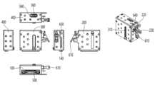
도2는 본 발명에서 제시하는 주변조직 채취를 할 수 있는 수술기구의 정면, 측면 및 평면도 등을 도시하고 있다.Figure 2 shows the front, side and top views of a surgical instrument capable of collecting surrounding tissue presented in the present invention.
본체(100)는 상판(400), 제1측판(200) 및 제2측판(300)으로 감싸지고, 내부에는 암세포 주변 조직을 일정한 크기 및 깊이로 절개하여 채취할 수 있게 하는 커터부(500)가 위치한다.The
술자는 상기 수술기구의 저면을 암세포 주변 조직에 고정시킨 후 상기 커터부를 사출하여 일정하고 고른 형상을 갖는 조직세포를 얻을 수 있다.After fixing the lower surface of the surgical instrument to the tissue surrounding the cancer cells, the surgeon may inject the cutter part to obtain tissue cells having a constant and even shape.
도3은 상기 수술기구의 내부 결합상태를 보여주는 일실시예를 도시하고 있다.Figure 3 shows an embodiment showing the internal coupling state of the surgical instrument.
상기 본체(100)은 측면에 제1슬릿(110)이 형성되어 있고 상기 슬릿을 통해 커터부(500)와 용수철부가 직접적으로 연결된다.The
상기 본체(100)의 일측에는 커터부(500)가 그리고 타측에는 용수철부(700)가 내재되며 상기 용수철부(700)의 압축 탄성력을 상기 커터부(500)의 운동에너지로 전환하며 상기 제1슬릿(110)을 따라 상기 커터부(500)가 하부로 사출되는 메커니즘을 갖는다.The
상기 커터부(500)는 제2슬릿(520)이 형성된 고정부(510) 및 상기 고정부(510) 하단에 상기 슬릿을 관통하는 제1돌기(540)가 형성된 연결부(530), 상기 연결부(530) 하단과 탈착가능하게 연결되는 커터(550) 및 상기 커터(550) 하단의 날부분을 외부로부터 보호하기 위해 씌워 놓은 캡(560)을 포함한다.The
또한 상기 용수철부(700)는 상기 본체에 힌지 가능하게 부착되는 제1로드(710), 상기 제1로드 (710) 외주면에 배치되는 제1스프링(720), 상기 제1로드(710) 내주면에 삽이되어 왕복 운동하는 제2로드(730) 및 상기 제2로드(730) 단부와 제1핀(750)으로 힌지 연결되는 레칭부(740)를 포함한다.In addition, the
상기 조정부(600)는 본체 일측에 힌지 가능하게 결합된 푸쉬부(120)와 치차 결합된 안착부(620), 상기 안착부와 제2스프링(650)을 매개로 결합하는 안전장치(630) 및 상기 안전장치(630)와 일체로 형성되며, 상기 안전장치를 좌우로 회전할 수 있는 손잡이(640) 및 상기 안착부(620)의 일측 단부와 제3핀(660)으로 힌지 가능하게 결합하는 레버부(610)를 포함한다.The
먼저 환자의 조직을 일정한 깊이와 일정한 모양으로 채취하기 위한 커터(550) 단부는 폐곡선 모양의 중공을 갖는 형상을 갖는다.First, the end of the
상기 폐곡선 형상의 커터(550) 중공부가 암세포 주변 조직을 절개하여 일정한 깊이와 모양의 조직을 채취할 수 있다.The hollow part of the
본 발명의 실시예에 따른 수술기구를 사용하기 전 상기 레칭부(740)는 상기 안착부(620)에 얹혀져 상기 제1스프링(720)이 탄성 압축력을 유지하는 제1위치를 유지한다.Before using the surgical instrument according to the embodiment of the present invention, the latching
이때 상기 제2로드(730)은 상기 제1로드(710)에 삽입되어 외주면에 놓인 제1스프링(720)이 압축될 수 있도록 전체 길이를 짧게 한다.At this time, the
상기 레칭부(740)는 제1핀(750)으로 상기 제1슬릿(110)을 관통하여 상기 제1돌기(540) 및 고정부(510)과 연결되어 있으므로 상기 레칭부(740)이 상기 제1스프링(720)의 압축 탄성력이 해제되어 운동 에너지로 전환된다면, 상기 레칭부(740)와 함께 일체로 연결된 고정부(510), 연결부(530) 및 커터(550)은 함께 본체(100) 하단으로 사출될 것이다.Since the latching
상기 용수철부(700)의 상기 제1스프링(720)이 탄성 압축력을 유지하는 제1위치일 때 상기 안착부(620)은 상기 푸쉬부(120)와 치차 결합되어 있으며 이때 상기 푸쉬부는 상기 레칭부(740)와 분리되어 있다.When the
상기 레버부(610)를 조작할 경우 상기 안전부(620)은 상기 제3핀(660)과의 결합에 의해 본체 외부로 당겨지게 되고, 상기 당겨진 안전부(620)로 인해 상기 레칭부(740)는 지지점을 잃게 된다.When the
도4는 상기 레버부(610)이 조작되어 상기 안전부(620)가 당겨진 경우 상기 용수철부(700)와 커터부(500)의 사출 메커니즘을 도시하고 있다.4 illustrates an ejection mechanism of the
상기 레버부(610)의 조작에 의해 상기 안전부(620)는 당겨지며 필연적으로 치차 결합된 상기 푸쉬부(120)를 회전시키게 된다.The
상기 푸쉬부(120) 일측은 방아쇠 형상을 하고 있어 회전하며 상기 레칭부(740)를 상기 제1슬릿(110) 방향으로 밀어줌으로서 상기 레칭부(740)와 연결된 상기 커터부(500)도 정확히 사출되게 된다.One side of the
설령 상기 푸쉬부(120)를 제거하여도 상기 레칭부(740)는 안착부(620)와의 접촉을 잃어 제1슬릿(110)을 따라 사출될 수 있으나, 수술 상황과 같이 긴급한 상황에서 본체 변형 등으로 정확한 사출이 진행되지 않는 점을 보완하는데 상기 푸쉬부(120)의 역할이 있다고 할 수 있다.Even if the
사출된 상기 커터부(500)는 상기 레칭부(740)가 상기 제1슬릿(110)의 하단부에 닿는 거리만큼인 제2위치까지 사출되며, 상기 사출거리가 환자의 조직세포를 채취하기 위해 상기 커터(550)가 조직을 침투하는 길이가 된다.The ejected
조직의 종류, 환자의 상태 등에 따라 상기 사출력의 크기는 상기 제1스프링(720)의 탄성계수를 조절하거나, 상기 제1 및 제2로드의 행정길이 또는 제1슬릿(110)의 길이를 조절하여 변경할 수 있다.Depending on the type of tissue, the condition of the patient, etc., the size of the ejection force adjusts the modulus of elasticity of the
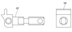
도5에는 상기 레버부(610)가 안착부(620)를 조정하는 메커니즘이 도시되어 있다.5 shows a mechanism in which the
상기 안착부(610)와 레버부(610)은 제2스프링(650)을 매개로 내부에 안전장치(630)과 결합한 잠금부(640)와 연결되어 있다The
상기 레버부(610)이 당겨지면 상기 제3핀(660)으로 연결된 상기 안착부(620)은 상기 잠금장치(630) 내부를 관통하여 당겨지게 되고, 이에 따라 치차 결합되어 있던 상기 푸쉬부(120)가 힌지 회전하면서 상기 레칭부(740)를 밀게 된다.When the
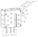
도6은 상기 커터부(500)가 사출되어 제2위치까지 도달한 후 다시 제1위치로 견인하는 메커니즘을 도시하고 있다.6 shows a mechanism for pulling the
상기 본체(100) 일측에 형성된 고정홈(150)에는 제1손잡이(130)가 고정되어 있으며, 상기 고정부(510) 일측은 상기 제1측판(200) 일측에 형성된 제4슬릿(400)을 통해 제2손잡이(800)와 힌지 결합되어 있다.A
상기 제2손잡이(800)의 타측은 상기 제1측판(200)에 형성된 홈부(230)와 힌지 결합되어 있어 상방으로 당기면 커버부(500)의 사출 압력을 증가시켜 저항이 강한 조직의 절삭을 편리하게 하고, 만일 술자가 환자의 조직 세포 채취부위를 위해 본 발명의 일실시예의 수술기구의 커터부(500)를 사출하여 조직 세포를 얻었을 경우 이를 회수하기 위해 상기 제1손잡이(130)로 상기 수술기구를 고정시킨 후 상기 제2손잡이(800)를 하방으로 내리면 해제되었던 상기 제1스프링(720)이 탄성 압축력을 받으면서 상기 고정부(510)와 연결된 커터부(500)와 함께 지렛대 원리에 의해 상기 제4슬릿(210)을 따라 상기 제1위치로 복귀하게 된다.The other side of the
도7은 상기 제2손잡이(800)를 하방으로 내려서 상기 커터부(500)가 복귀하는 메커니즘을 도시하고 있으나, 이는 본 발명이 속하는 기술범위에서 보통의 지식을 가진 자에 의해 다른 메커니즘으로 구현될 수도 있다.7 shows a mechanism in which the
상기 제1위치가 되었을 때 상기 연결부(530) 상단에 형성된 제1돌기(540)는 상기 제2슬릿(520) 및 상기 상판(400)의 제3슬릿(410)위로 돌출하게 된다.When it reaches the first position, the
상기 제1돌기(540) 측면에는 홈이 형성되어 있으며, 상기 고정부(510) 일측면에 제3스프링(580)을 매개로 제2핀(570)으로 제2슬릿(520) 방향으로 이동 가능하게 고정되며, 동시에 상기 제1핀(750)에 의해 상기 레칫부(740)와 결합된 스위치(560)의 일측에 형성된 제2돌기와 결합하게 된다.A groove is formed on the side of the
상기 스위치(560)을 전후진 시킬 경우 상기 제1돌기(540)의 홈에 상기 스위치(560)의 제2돌기가 끼워진다.When the
이때 상기 스위치(560)와 같이 상기 레칫부(740)는 전후진하며 상기 안착부(620)에 얹혀지게 되어 다시 제1위치에서 사출할 수 있는 준비가 완료된다.At this time, like the
상기 도8은 커터(550)의 다양한 형태를 도시하고 있다.8 shows various forms of the
커터는 조직 채취를 위해 사용할 경우 폐곡선 형태의 단면을 갖는 단부가 무뎌질 수 있고 또한 위생상 문제로 인하여 교체 가능하여야 한다.When the cutter is used for tissue collection, an end having a closed curved cross-section may become dull and should be replaceable due to hygiene problems.
상기 도시된 커터(550) 상단에 형성된 홈은 상기 연결부(530)에 형성된 제3돌기와 탈착결합 가능하게 설계되어 술자의 판단에 따라 수술에 맞는 형태의 커터를 교체하여 장착할 수 있다.The groove formed on the top of the
특히 유방 등 절제 수술 대상은 지방, 실질, 근육 등 다양한 강도와 상태를 갖고 그 위치 또한 좁거나 경사질 수 있으므로 술자는 이에 맞게 여러 종류의 커터(550)를 선택할 수 있어야 한다.In particular, since subjects for mastectomy surgery have various strengths and conditions, such as fat, substance, and muscle, and their positions may be narrow or inclined, the surgeon should be able to select several types of
상기 커터(550)의 폐곡선 단면 또한 절제 수술의 종류 및 수술 부위에 따라 다양하게 변경될 수 있음은 자명하다.It is obvious that the cross section of the closed curve of the
본 발명의 일실시예로서 도8은 커터(550)가 일자형, 만곡형, 반달형, 톱니형 등 수술환경 및 환부의 상태에 따라 여러 형태로 만들어져 사용될 수 있음을 도시하고 있으며 그 크기 역시 사용환경 및 채취해야 하는 조직의 종류, 신체 위치 등에 따라 조정될 수 있을 것이다.As an embodiment of the present invention, Figure 8 shows that the
도9은 상기 커터부(500)의 사출 거리를 조절하기 위한 멈춤쇠(320) 시스템을 도시하고 있다.9 shows a
상기 멈춤쇠(320)은 제2측편(300)의 일측에 형성된 제5슬릿(310)을 따라 나사 등의 체결방법으로 고정 가능하다.The
술자는 암세포의 크기, 환자 상태, 임상 경험 등에 따라 조직세포를 채취할 범위를 결정할 수 있다. 즉, 상기 커터(550)가 절개해야 할 깊이도 다양하게 술자의 판단에 따라 조정할 수 있어야 한다.The surgeon can determine the extent to which tissue cells are to be harvested according to the size of cancer cells, the patient's condition, clinical experience, and the like. That is, the depth to be incised by the
상기 멈춤쇠(320)은 상기 레칫부(740)이 제1슬릿(110)을 따라 사출되는 경로상에 위치하게 되며, 이에 따라 상기 레버부(610)의 조작에 따라 상기 커터부(500)가 사출될 때 상기 레칫부(740)의 사출을 정지시킴으로서 전체 사출거리를 조절하게 된다.The
상기 제2측판(300)의 제5슬릿(310) 일측에는 눈금 등 기준선이 도시되어 있어 술자는 원하는 채취 깊이를 먼저 멈춤쇠(320)의 위치로 조정한 후 상기 커터(550)를 사출한다.A reference line, such as a scale, is shown on one side of the
상기 멈춤쇠(320)의 재질은 본 발명의 실시예에 따른 수술기구를 사용하는 환경 중 사출을 멈출 때 발생하는 충격력이 조직 세포 채취에 지장이 주지 않을 정도의 완충능력을 갖출 수 있다.The material of the
도10는 상기 수술기구의 사용이 완료되었거나, 또는 수술 중 술자의 실수로 상기 레버부(610)를 잘못 조작하여 상기 커터(550)이 사출되는 것을 방지하기 위해 사용하는 안전잠금 장치를 도시하고 있다.FIG. 10 shows a safety locking device used to prevent the
상기 안착부(620)의 단부는 직사각형 또는 부정형의 형상을 갖으며, 상기 상기 단부와 동일한 형상을 갖는 안전장치(630)로 삽입되어 상기 레버부(610)과 연결된다.An end of the
상기 안전장치(630)는 외부에 잠금부(640)와 일체로 연결되어 있으며, 상기 잠금부(640)는 손잡이 등으로 상기 안전장치를 동시에 회전시킬 수 있으며, 상기 회전된 잠금부(640)은 단면이 상기 안착부(620)의 단부와 일치하지 않게 되어 상기 레버부(610)에 의한 조작에 대해서도 상기 안착부(620)는 이동할 수 없게 되어 상기 레칫부(740)가 제1위치를 벗어나지 않게 할 수 있다.The
전술한 본 발명의 설명은 예시를 위한 것이며, 본 발명이 속하는 기술분야의 통상의 지식을 가진 자는 본 발명의 기술적 사상이나 필수적인 특징을 변경하지 않고서 다른 구체적인 형태로 쉽게 변형이 가능하다는 것을 이해할 수 있을 것이다. 그러므로 이상에서 기술한 실시예들은 모든 면에서 예시적인 것이며 한정적이 아닌 것으로 이해해야만 한다. 예를 들어, 단일형으로 설명되어 있는 각 구성 요소는 분산되어 실시될 수도 있으며, 마찬가지로 분산된 것으로 설명되어 있는 구성 요소들도 결합된 형태로 실시될 수 있다.The above description of the present invention is for illustrative purposes, and those skilled in the art can understand that it can be easily modified into other specific forms without changing the technical spirit or essential features of the present invention. will be. Therefore, the embodiments described above should be understood as illustrative in all respects and not limiting. For example, each component described as a single type may be implemented in a distributed manner, and similarly, components described as distributed may be implemented in a combined form.
본 발명의 범위는 후술하는 특허청구범위에 의하여 나타내어지며, 특허청구범위의 의미 및 범위 그리고 그 균등 개념으로부터 도출되는 모든 변경 또는 변형된 형태가 본 발명의 범위에 포함되는 것으로 해석되어야 한다.The scope of the present invention is indicated by the following claims, and all changes or modifications derived from the meaning and scope of the claims and equivalent concepts should be interpreted as being included in the scope of the present invention.
100: 본체
110: 제1슬릿
120: 푸쉬바
130: 제1손잡이
140: 제6슬릿
150: 고정홈
200: 제1측판
210: 제4슬릿
220: 홈부
300: 제2측판
310: 제5슬릿
320: 멈춤쇠
400: 상판
410: 제3슬릿
500: 커터부
510: 고정부
520: 제2슬릿
530: 연결부
540: 제1돌기
550: 커터
560: 스위치
570: 제2핀
580: 제3스프링
600: 조정부
610: 레버부
620: 안착부
630: 안전장치
640: 잠금부
650: 제2스프링
700: 용수철부
710: 제1로드
720: 제1스프링
730: 제2로드
740: 레칫부
750: 제1핀
800: 제2손잡이100: body
110: first slit
120: push bar
130: first handle
140: sixth slit
150: fixed groove
200: first side plate
210: fourth slit
220: groove
300: second side plate
310: fifth slit
320: detent
400: top plate
410: third slit
500: cutter part
510: fixing part
520: second slit
530: connection part
540: first protrusion
550: cutter
560: switch
570: second pin
580: third spring
600: adjustment unit
610: lever part
620: seating part
630: safety device
640: locking part
650: second spring
700: spring part
710: first load
720: first spring
730: second load
740: lettbu
750: first pin
800: second handle
Claims (13)
Translated fromKorean상기 본체(100) 일측에 배치되는 커터부(500);
상기 제1슬릿(110)을 통해 상기 커터부(500)와 연결된 용수철부(700);
상기 본체(100) 타측에 배치되며 상기 용수철부(700) 일단과 밀착되어 상기 용수철부(700)가 압축 탄성력을 갖도록 위치를 고정시키는 조정부(600)로 이루어진 수술용 절개 기구에 있어서,
상기 조정부(600) 일단에 위치한 레버(610)를 통해 상기 용수철부(700)와 조정부(600)의 밀착을 해제함으로써 상기 용수철부(700)가 이완되며 상기 커터부(500)가 상기 제1슬릿(110)을 따라 사출되도록 하는 것을 특징으로 하는 수술기구
A main body 100 having a first slit 110 formed on one side thereof;
a cutter part 500 disposed on one side of the main body 100;
a spring part 700 connected to the cutter part 500 through the first slit 110;
In the surgical incision instrument composed of an adjusting part 600 disposed on the other side of the main body 100 and in close contact with one end of the spring part 700 to fix the position so that the spring part 700 has a compressive elastic force,
The spring part 700 is released by releasing the close contact between the spring part 700 and the adjusting part 600 through the lever 610 located at one end of the adjusting part 600, and the cutter part 500 moves through the first slit. Surgical instrument, characterized in that to be ejected along (110)
상기 커터부(500)는 제2슬릿(520)이 형성된 고정부(510), 상기 고정부(510) 하단에 위치하며 상기 제2슬릿(520)을 관통하여 제1핀(750)과 제1슬릿(110)을 통해 결합된 스위치(560)와 탈착 가능하게 결합되는 제1돌기(540)가 형성된 연결부(530), 상기 연결부 하단에 탈착 가능하게 결합하며 폐곡선 단면을 갖는 커터(550) 및 상기 커터(550) 하단에 개폐 가능하게 결합하는 캡(570)을 포함하는 것을 특징으로 하는 수술기구
The method of claim 1,
The cutter part 500 is located at the lower end of the fixing part 510 in which the second slit 520 is formed, and passes through the second slit 520 to form the first pin 750 and the first pin 750. A connector 530 formed with a first protrusion 540 detachably coupled to the switch 560 coupled through the slit 110, a cutter 550 detachably coupled to the lower end of the connector and having a closed curved cross section, and the Surgical instrument comprising a cap 570 coupled to be openable and openable at the bottom of the cutter 550
상기 본체(100)는 상단에 제3슬릿(410)이 형성된 상판(400), 측면 일측에 제4슬릿(210)이 형성된 제1측판(200) 및 측면 타측에는 제5슬릿(310)이 형성된 제2측판(300)과 결합되어 있는 것을 특징으로 하는 수술기구
The method of claim 1,
The main body 100 includes a top plate 400 having a third slit 410 formed thereon, a first side plate 200 having a fourth slit 210 formed thereon on one side of the side, and a fifth slit 310 formed thereon on the other side of the side. Surgical instrument, characterized in that coupled to the second side plate 300
상기 용수철부(700)는 상기 본체(100)와 힌지 연결되는 제1로드(710), 상기 제1로드(710) 외주면에 배치되는 제1스프링(720), 상기 제1로드(710) 내주면에 삽입되며 일측 단부는 레칫부(740)와 결합하는 제2로드(730) 및 상기 제2로드(730) 및 레칫부(740)의 결합부를 관통하여 상기 고정부(510)와 힌지 결합시키는 제1핀(750)을 포함하는 것을 특징으로 하는 수술기구
The method of claim 2,
The spring part 700 includes a first rod 710 hingedly connected to the main body 100, a first spring 720 disposed on an outer circumferential surface of the first rod 710, and an inner circumferential surface of the first rod 710. The second rod 730 coupled with the ratchet part 740 and the second rod 730 and the ratchet part 740 are inserted into the second rod 730 and the ratchet part 740 are hingedly coupled to the fixing part 510. Surgical instrument comprising a pin (750)
상기 조정부(600)는 상기 본체(100)에 힌지 연결된 푸쉬부(120), 상기 푸쉬부(120) 하단과 치차 결합된 상태로 상기 제1스프링(720)의 탄성 압축력에 의해 상기 커터부(500)가 사출 준비가 되는 제1위치에 상기 레칫부(740)를 고정하는 안착부(620), 상기 안착부(620) 타측 단부와 제2스프링(650)을 매개로 결합하며 상기 안착부(620)를 이동시켜 상기 레칫부(740)의 위치 고정을 해제함으로써 상기 커터부(500)가 최대 사출거리인 제2위치까지 제1슬릿(110)을 따라 사출되도록 하는 레버부(610)를 포함하는 것을 특징으로 하는 수술기구
The method of claim 4,
The adjustment unit 600 is connected to the lower end of the push unit 120 hinged to the main body 100 and the cutter unit 500 by the elastic compression force of the first spring 720. ) is coupled to the seating portion 620 for fixing the ratchet portion 740 in a first position ready for injection, the other end of the seating portion 620 and the second spring 650, and the seating portion 620 ) to release the position fixation of the ratchet part 740 so that the cutter part 500 is ejected along the first slit 110 to the second position, which is the maximum injection distance, including a lever part 610 characterized in that the surgical instrument
상기 푸쉬부(120)는 상기 안착부(620)가 이동하면 치차결합에 의해 회전하며 상기 레칫부(740)에 압력을 제공함으로써 상기 커터부(500)가 상기 제1슬릿(110)을 따라 원활하게 사출되도록 유도하는 것을 특징으로 하는 수술기구
The method of claim 5,
The push part 120 rotates by gear coupling when the seating part 620 moves, and provides pressure to the ratchet part 740 so that the cutter part 500 smoothly follows the first slit 110. Surgical instrument, characterized in that for inducing to be ejected
상기 제1슬릿(110)을 따라 이동 가능하게 체결되는 멈춤쇠(320)가 상기 레칫부(740)의 사출이동 거리를 제한함으로써 상기 제2위치를 조절하는 것을 특징으로 하는 수술기구
The method of claim 5,
Surgical instrument, characterized in that the second position is adjusted by the detent 320 movably fastened along the first slit 110 by limiting the ejection movement distance of the ratchet part 740
상기 본체(100) 일측에 형성된 고정홈(150)에 고정된 제1손잡이(130), 상기 본체(100) 측면에 배치된 제1측판(200) 및 상기 제1측판(200)에 형성된 제4슬릿(210), 상기 제1측판(200) 일측에 형성된 홈부(220)와 일단이 힌지 연결되고 타단은 제4슬릿(210)을 통해 상기 고정부(510)와 힌지 결합되어 상기 본체(100) 상단방향으로 이동시켜 절삭압력을 강화하는 제2손잡이(800)를 포함하는 것을 특징으로 하는 수술기구
The method of claim 5,
The first handle 130 fixed to the fixing groove 150 formed on one side of the main body 100, the first side plate 200 disposed on the side of the main body 100, and the fourth formed on the first side plate 200 One end of the slit 210 and the groove part 220 formed on one side of the first side plate 200 is hinged, and the other end is hinged with the fixing part 510 through the fourth slit 210 to form the main body 100 Surgical instrument comprising a second handle 800 for intensifying the cutting pressure by moving in the upper direction
상기 스위치(560)는 상기 제2슬릿(520)을 따라 이동되어 상기 제1돌기(540)와 탈착되는 것을 특징으로 하는 수술기구
The method of claim 2,
The switch 560 is moved along the second slit 520 and is detached from the first protrusion 540.
상기 커터(550)의 단부는 절개 부위에 따라 직선형, 반달형, 만도형 또는 톱니형 중 하나의 형상을 갖는 것을 특징으로 하는 수술기구
The method of claim 2,
The end of the cutter 550 is a surgical instrument, characterized in that it has a shape of one of a straight, half-moon, machete or sawtooth shape according to the incision site
상기 안착부(620)의 직사각형 단부는 동일한 형상의 통공을 갖는 안전장치(630)를 관통하여 상기 레버부(610)와 체결되어, 상기 안전장치(630)을 회전시키면 상기 안착부(620) 단부가 안전장치(630) 내부로 왕복 운동하는 것을 제한하여 상기 커터부(500)가 제1위치에 고정되게 하는 것을 특징으로 하는 수술기구
The method of claim 5,
The rectangular end of the seating part 620 passes through a safety device 630 having a through hole of the same shape and is fastened to the lever part 610, and when the safety device 630 is rotated, the end of the seating part 620 Surgical instrument, characterized in that by limiting the reciprocating movement inside the safety device 630 so that the cutter portion 500 is fixed in the first position
상기 스위치(560)는 상기 고정부(510)의 일측을 관통하는 제2핀(570)과 스프링을 매개로 결합되는 것을 특징으로 하는 수술기구
The method of claim 9,
The switch 560 is a surgical instrument, characterized in that coupled to the second pin 570 penetrating one side of the fixing part 510 via a spring
상기 본체(100) 일측에는 제6슬릿(140)이 형성되어 있어 커터부(500)의 사출 위치를 외부에서 확인할 수 있는 것을 특징으로 하는 수술기구
The method of claim 2,
A sixth slit 140 is formed on one side of the main body 100, so that the ejection position of the cutter part 500 can be confirmed from the outside.
Priority Applications (1)
| Application Number | Priority Date | Filing Date | Title |
|---|---|---|---|
| KR1020220099117AKR102539420B1 (en) | 2022-08-09 | 2022-08-09 | A Surgical Equipment |
Applications Claiming Priority (1)
| Application Number | Priority Date | Filing Date | Title |
|---|---|---|---|
| KR1020220099117AKR102539420B1 (en) | 2022-08-09 | 2022-08-09 | A Surgical Equipment |
Publications (1)
| Publication Number | Publication Date |
|---|---|
| KR102539420B1true KR102539420B1 (en) | 2023-06-01 |
Family
ID=86770559
Family Applications (1)
| Application Number | Title | Priority Date | Filing Date |
|---|---|---|---|
| KR1020220099117AActiveKR102539420B1 (en) | 2022-08-09 | 2022-08-09 | A Surgical Equipment |
Country Status (1)
| Country | Link |
|---|---|
| KR (1) | KR102539420B1 (en) |
Citations (7)
| Publication number | Priority date | Publication date | Assignee | Title |
|---|---|---|---|---|
| KR200182997Y1 (en) | 1999-12-31 | 2000-05-15 | 이희영 | Ligthing device attached with a mammary retractor, a nasal retractor and a nasal speculum |
| KR20100024571A (en)* | 2008-08-26 | 2010-03-08 | 박수희 | Injector for fine-needle aspiration biopsy |
| KR101551311B1 (en)* | 2013-08-21 | 2015-09-08 | 한국기계연구원 | Pistol type biopsy device |
| KR102117014B1 (en)* | 2018-01-26 | 2020-05-29 | 고형진 | Core biopsy device |
| KR102232778B1 (en)* | 2020-11-26 | 2021-03-26 | 주식회사 그린메디칼서플라이 | Biopsy Device having Exterior Penetration Needle Locking Member |
| KR102253461B1 (en) | 2016-08-02 | 2021-05-17 | 히데히로 야마모토 | Microscopic endoscopic surgical instruments |
| KR20220088665A (en)* | 2019-11-22 | 2022-06-28 | 주식회사 플라워메디칼 | Core biopsy device |
- 2022
- 2022-08-09KRKR1020220099117Apatent/KR102539420B1/enactiveActive
Patent Citations (7)
| Publication number | Priority date | Publication date | Assignee | Title |
|---|---|---|---|---|
| KR200182997Y1 (en) | 1999-12-31 | 2000-05-15 | 이희영 | Ligthing device attached with a mammary retractor, a nasal retractor and a nasal speculum |
| KR20100024571A (en)* | 2008-08-26 | 2010-03-08 | 박수희 | Injector for fine-needle aspiration biopsy |
| KR101551311B1 (en)* | 2013-08-21 | 2015-09-08 | 한국기계연구원 | Pistol type biopsy device |
| KR102253461B1 (en) | 2016-08-02 | 2021-05-17 | 히데히로 야마모토 | Microscopic endoscopic surgical instruments |
| KR102117014B1 (en)* | 2018-01-26 | 2020-05-29 | 고형진 | Core biopsy device |
| KR20220088665A (en)* | 2019-11-22 | 2022-06-28 | 주식회사 플라워메디칼 | Core biopsy device |
| KR102232778B1 (en)* | 2020-11-26 | 2021-03-26 | 주식회사 그린메디칼서플라이 | Biopsy Device having Exterior Penetration Needle Locking Member |
Similar Documents
| Publication | Publication Date | Title |
|---|---|---|
| JP4659014B2 (en) | Biological tissue cutting device | |
| JP3845023B2 (en) | Incisional biopsy device and method | |
| US6638235B2 (en) | Biopsy apparatus | |
| JP3679368B2 (en) | Incisional biopsy device and method | |
| US4651752A (en) | Biopsy needle | |
| JPH06507099A (en) | Experimental resection instrument with steerable stylet and cannula | |
| US7029451B2 (en) | Excisional devices having selective cutting and atraumatic configurations and methods of using same | |
| JP2022512149A (en) | Biopsy system with end-deploying needle | |
| KR102539420B1 (en) | A Surgical Equipment | |
| GB2397242A (en) | A tissue cutting device consisting of an outer cannula and an inner cutting member coupled to a drive mechanism | |
| AU2002336282B2 (en) | Excisional Biopsy Devices and Methods |
Legal Events
| Date | Code | Title | Description |
|---|---|---|---|
| PA0109 | Patent application | Patent event code:PA01091R01D Comment text:Patent Application Patent event date:20220809 | |
| PA0201 | Request for examination | ||
| PA0302 | Request for accelerated examination | Patent event date:20220902 Patent event code:PA03022R01D Comment text:Request for Accelerated Examination Patent event date:20220809 Patent event code:PA03021R01I Comment text:Patent Application | |
| PE0902 | Notice of grounds for rejection | Comment text:Notification of reason for refusal Patent event date:20230109 Patent event code:PE09021S01D | |
| E701 | Decision to grant or registration of patent right | ||
| PE0701 | Decision of registration | Patent event code:PE07011S01D Comment text:Decision to Grant Registration Patent event date:20230503 | |
| GRNT | Written decision to grant | ||
| PR0701 | Registration of establishment | Comment text:Registration of Establishment Patent event date:20230530 Patent event code:PR07011E01D | |
| PR1002 | Payment of registration fee | Payment date:20230530 End annual number:3 Start annual number:1 | |
| PG1601 | Publication of registration |