KR102535728B1 - Manufactured method of a covered stent and a covered stent by manufactured method thereof - Google Patents
Manufactured method of a covered stent and a covered stent by manufactured method thereofDownload PDFInfo
- Publication number
- KR102535728B1 KR102535728B1KR1020210064307AKR20210064307AKR102535728B1KR 102535728 B1KR102535728 B1KR 102535728B1KR 1020210064307 AKR1020210064307 AKR 1020210064307AKR 20210064307 AKR20210064307 AKR 20210064307AKR 102535728 B1KR102535728 B1KR 102535728B1
- Authority
- KR
- South Korea
- Prior art keywords
- elastic member
- stent
- ptfe
- cylindrical body
- jig
- Prior art date
- Legal status (The legal status is an assumption and is not a legal conclusion. Google has not performed a legal analysis and makes no representation as to the accuracy of the status listed.)
- Active
Links
Images


Classifications
- A—HUMAN NECESSITIES
- A61—MEDICAL OR VETERINARY SCIENCE; HYGIENE
- A61F—FILTERS IMPLANTABLE INTO BLOOD VESSELS; PROSTHESES; DEVICES PROVIDING PATENCY TO, OR PREVENTING COLLAPSING OF, TUBULAR STRUCTURES OF THE BODY, e.g. STENTS; ORTHOPAEDIC, NURSING OR CONTRACEPTIVE DEVICES; FOMENTATION; TREATMENT OR PROTECTION OF EYES OR EARS; BANDAGES, DRESSINGS OR ABSORBENT PADS; FIRST-AID KITS
- A61F2/00—Filters implantable into blood vessels; Prostheses, i.e. artificial substitutes or replacements for parts of the body; Appliances for connecting them with the body; Devices providing patency to, or preventing collapsing of, tubular structures of the body, e.g. stents
- A61F2/02—Prostheses implantable into the body
- A61F2/04—Hollow or tubular parts of organs, e.g. bladders, tracheae, bronchi or bile ducts
- A61F2/06—Blood vessels
- A61F2/07—Stent-grafts
- A—HUMAN NECESSITIES
- A61—MEDICAL OR VETERINARY SCIENCE; HYGIENE
- A61F—FILTERS IMPLANTABLE INTO BLOOD VESSELS; PROSTHESES; DEVICES PROVIDING PATENCY TO, OR PREVENTING COLLAPSING OF, TUBULAR STRUCTURES OF THE BODY, e.g. STENTS; ORTHOPAEDIC, NURSING OR CONTRACEPTIVE DEVICES; FOMENTATION; TREATMENT OR PROTECTION OF EYES OR EARS; BANDAGES, DRESSINGS OR ABSORBENT PADS; FIRST-AID KITS
- A61F2/00—Filters implantable into blood vessels; Prostheses, i.e. artificial substitutes or replacements for parts of the body; Appliances for connecting them with the body; Devices providing patency to, or preventing collapsing of, tubular structures of the body, e.g. stents
- A61F2/82—Devices providing patency to, or preventing collapsing of, tubular structures of the body, e.g. stents
- A61F2/844—Devices providing patency to, or preventing collapsing of, tubular structures of the body, e.g. stents folded prior to deployment
- A—HUMAN NECESSITIES
- A61—MEDICAL OR VETERINARY SCIENCE; HYGIENE
- A61F—FILTERS IMPLANTABLE INTO BLOOD VESSELS; PROSTHESES; DEVICES PROVIDING PATENCY TO, OR PREVENTING COLLAPSING OF, TUBULAR STRUCTURES OF THE BODY, e.g. STENTS; ORTHOPAEDIC, NURSING OR CONTRACEPTIVE DEVICES; FOMENTATION; TREATMENT OR PROTECTION OF EYES OR EARS; BANDAGES, DRESSINGS OR ABSORBENT PADS; FIRST-AID KITS
- A61F2/00—Filters implantable into blood vessels; Prostheses, i.e. artificial substitutes or replacements for parts of the body; Appliances for connecting them with the body; Devices providing patency to, or preventing collapsing of, tubular structures of the body, e.g. stents
- A61F2/82—Devices providing patency to, or preventing collapsing of, tubular structures of the body, e.g. stents
- A61F2/848—Devices providing patency to, or preventing collapsing of, tubular structures of the body, e.g. stents having means for fixation to the vessel wall, e.g. barbs
- A—HUMAN NECESSITIES
- A61—MEDICAL OR VETERINARY SCIENCE; HYGIENE
- A61L—METHODS OR APPARATUS FOR STERILISING MATERIALS OR OBJECTS IN GENERAL; DISINFECTION, STERILISATION OR DEODORISATION OF AIR; CHEMICAL ASPECTS OF BANDAGES, DRESSINGS, ABSORBENT PADS OR SURGICAL ARTICLES; MATERIALS FOR BANDAGES, DRESSINGS, ABSORBENT PADS OR SURGICAL ARTICLES
- A61L31/00—Materials for other surgical articles, e.g. stents, stent-grafts, shunts, surgical drapes, guide wires, materials for adhesion prevention, occluding devices, surgical gloves, tissue fixation devices
- A61L31/02—Inorganic materials
- A61L31/022—Metals or alloys
- A—HUMAN NECESSITIES
- A61—MEDICAL OR VETERINARY SCIENCE; HYGIENE
- A61L—METHODS OR APPARATUS FOR STERILISING MATERIALS OR OBJECTS IN GENERAL; DISINFECTION, STERILISATION OR DEODORISATION OF AIR; CHEMICAL ASPECTS OF BANDAGES, DRESSINGS, ABSORBENT PADS OR SURGICAL ARTICLES; MATERIALS FOR BANDAGES, DRESSINGS, ABSORBENT PADS OR SURGICAL ARTICLES
- A61L31/00—Materials for other surgical articles, e.g. stents, stent-grafts, shunts, surgical drapes, guide wires, materials for adhesion prevention, occluding devices, surgical gloves, tissue fixation devices
- A61L31/04—Macromolecular materials
- A61L31/048—Macromolecular materials obtained by reactions only involving carbon-to-carbon unsaturated bonds
- A—HUMAN NECESSITIES
- A61—MEDICAL OR VETERINARY SCIENCE; HYGIENE
- A61L—METHODS OR APPARATUS FOR STERILISING MATERIALS OR OBJECTS IN GENERAL; DISINFECTION, STERILISATION OR DEODORISATION OF AIR; CHEMICAL ASPECTS OF BANDAGES, DRESSINGS, ABSORBENT PADS OR SURGICAL ARTICLES; MATERIALS FOR BANDAGES, DRESSINGS, ABSORBENT PADS OR SURGICAL ARTICLES
- A61L31/00—Materials for other surgical articles, e.g. stents, stent-grafts, shunts, surgical drapes, guide wires, materials for adhesion prevention, occluding devices, surgical gloves, tissue fixation devices
- A61L31/08—Materials for coatings
- A61L31/10—Macromolecular materials
- B—PERFORMING OPERATIONS; TRANSPORTING
- B29—WORKING OF PLASTICS; WORKING OF SUBSTANCES IN A PLASTIC STATE IN GENERAL
- B29C—SHAPING OR JOINING OF PLASTICS; SHAPING OF MATERIAL IN A PLASTIC STATE, NOT OTHERWISE PROVIDED FOR; AFTER-TREATMENT OF THE SHAPED PRODUCTS, e.g. REPAIRING
- B29C53/00—Shaping by bending, folding, twisting, straightening or flattening; Apparatus therefor
- B29C53/56—Winding and joining, e.g. winding spirally
- B29C53/566—Winding and joining, e.g. winding spirally for making tubular articles followed by compression
- B—PERFORMING OPERATIONS; TRANSPORTING
- B29—WORKING OF PLASTICS; WORKING OF SUBSTANCES IN A PLASTIC STATE IN GENERAL
- B29C—SHAPING OR JOINING OF PLASTICS; SHAPING OF MATERIAL IN A PLASTIC STATE, NOT OTHERWISE PROVIDED FOR; AFTER-TREATMENT OF THE SHAPED PRODUCTS, e.g. REPAIRING
- B29C53/00—Shaping by bending, folding, twisting, straightening or flattening; Apparatus therefor
- B29C53/80—Component parts, details or accessories; Auxiliary operations
- A—HUMAN NECESSITIES
- A61—MEDICAL OR VETERINARY SCIENCE; HYGIENE
- A61F—FILTERS IMPLANTABLE INTO BLOOD VESSELS; PROSTHESES; DEVICES PROVIDING PATENCY TO, OR PREVENTING COLLAPSING OF, TUBULAR STRUCTURES OF THE BODY, e.g. STENTS; ORTHOPAEDIC, NURSING OR CONTRACEPTIVE DEVICES; FOMENTATION; TREATMENT OR PROTECTION OF EYES OR EARS; BANDAGES, DRESSINGS OR ABSORBENT PADS; FIRST-AID KITS
- A61F2/00—Filters implantable into blood vessels; Prostheses, i.e. artificial substitutes or replacements for parts of the body; Appliances for connecting them with the body; Devices providing patency to, or preventing collapsing of, tubular structures of the body, e.g. stents
- A61F2/02—Prostheses implantable into the body
- A61F2/04—Hollow or tubular parts of organs, e.g. bladders, tracheae, bronchi or bile ducts
- A61F2/06—Blood vessels
- A61F2/07—Stent-grafts
- A61F2002/072—Encapsulated stents, e.g. wire or whole stent embedded in lining
- A—HUMAN NECESSITIES
- A61—MEDICAL OR VETERINARY SCIENCE; HYGIENE
- A61F—FILTERS IMPLANTABLE INTO BLOOD VESSELS; PROSTHESES; DEVICES PROVIDING PATENCY TO, OR PREVENTING COLLAPSING OF, TUBULAR STRUCTURES OF THE BODY, e.g. STENTS; ORTHOPAEDIC, NURSING OR CONTRACEPTIVE DEVICES; FOMENTATION; TREATMENT OR PROTECTION OF EYES OR EARS; BANDAGES, DRESSINGS OR ABSORBENT PADS; FIRST-AID KITS
- A61F2210/00—Particular material properties of prostheses classified in groups A61F2/00 - A61F2/26 or A61F2/82 or A61F9/00 or A61F11/00 or subgroups thereof
- A61F2210/0014—Particular material properties of prostheses classified in groups A61F2/00 - A61F2/26 or A61F2/82 or A61F9/00 or A61F11/00 or subgroups thereof using shape memory or superelastic materials, e.g. nitinol
- A—HUMAN NECESSITIES
- A61—MEDICAL OR VETERINARY SCIENCE; HYGIENE
- A61F—FILTERS IMPLANTABLE INTO BLOOD VESSELS; PROSTHESES; DEVICES PROVIDING PATENCY TO, OR PREVENTING COLLAPSING OF, TUBULAR STRUCTURES OF THE BODY, e.g. STENTS; ORTHOPAEDIC, NURSING OR CONTRACEPTIVE DEVICES; FOMENTATION; TREATMENT OR PROTECTION OF EYES OR EARS; BANDAGES, DRESSINGS OR ABSORBENT PADS; FIRST-AID KITS
- A61F2210/00—Particular material properties of prostheses classified in groups A61F2/00 - A61F2/26 or A61F2/82 or A61F9/00 or A61F11/00 or subgroups thereof
- A61F2210/0076—Particular material properties of prostheses classified in groups A61F2/00 - A61F2/26 or A61F2/82 or A61F9/00 or A61F11/00 or subgroups thereof multilayered, e.g. laminated structures
- A—HUMAN NECESSITIES
- A61—MEDICAL OR VETERINARY SCIENCE; HYGIENE
- A61F—FILTERS IMPLANTABLE INTO BLOOD VESSELS; PROSTHESES; DEVICES PROVIDING PATENCY TO, OR PREVENTING COLLAPSING OF, TUBULAR STRUCTURES OF THE BODY, e.g. STENTS; ORTHOPAEDIC, NURSING OR CONTRACEPTIVE DEVICES; FOMENTATION; TREATMENT OR PROTECTION OF EYES OR EARS; BANDAGES, DRESSINGS OR ABSORBENT PADS; FIRST-AID KITS
- A61F2220/00—Fixations or connections for prostheses classified in groups A61F2/00 - A61F2/26 or A61F2/82 or A61F9/00 or A61F11/00 or subgroups thereof
- A61F2220/0008—Fixation appliances for connecting prostheses to the body
- A—HUMAN NECESSITIES
- A61—MEDICAL OR VETERINARY SCIENCE; HYGIENE
- A61F—FILTERS IMPLANTABLE INTO BLOOD VESSELS; PROSTHESES; DEVICES PROVIDING PATENCY TO, OR PREVENTING COLLAPSING OF, TUBULAR STRUCTURES OF THE BODY, e.g. STENTS; ORTHOPAEDIC, NURSING OR CONTRACEPTIVE DEVICES; FOMENTATION; TREATMENT OR PROTECTION OF EYES OR EARS; BANDAGES, DRESSINGS OR ABSORBENT PADS; FIRST-AID KITS
- A61F2220/00—Fixations or connections for prostheses classified in groups A61F2/00 - A61F2/26 or A61F2/82 or A61F9/00 or A61F11/00 or subgroups thereof
- A61F2220/0025—Connections or couplings between prosthetic parts, e.g. between modular parts; Connecting elements
- A61F2220/0075—Connections or couplings between prosthetic parts, e.g. between modular parts; Connecting elements sutured, ligatured or stitched, retained or tied with a rope, string, thread, wire or cable
- A—HUMAN NECESSITIES
- A61—MEDICAL OR VETERINARY SCIENCE; HYGIENE
- A61F—FILTERS IMPLANTABLE INTO BLOOD VESSELS; PROSTHESES; DEVICES PROVIDING PATENCY TO, OR PREVENTING COLLAPSING OF, TUBULAR STRUCTURES OF THE BODY, e.g. STENTS; ORTHOPAEDIC, NURSING OR CONTRACEPTIVE DEVICES; FOMENTATION; TREATMENT OR PROTECTION OF EYES OR EARS; BANDAGES, DRESSINGS OR ABSORBENT PADS; FIRST-AID KITS
- A61F2240/00—Manufacturing or designing of prostheses classified in groups A61F2/00 - A61F2/26 or A61F2/82 or A61F9/00 or A61F11/00 or subgroups thereof
- A61F2240/001—Designing or manufacturing processes
- A61F2240/002—Designing or making customized prostheses
- A61F2240/004—Using a positive or negative model, e.g. moulds
- A—HUMAN NECESSITIES
- A61—MEDICAL OR VETERINARY SCIENCE; HYGIENE
- A61F—FILTERS IMPLANTABLE INTO BLOOD VESSELS; PROSTHESES; DEVICES PROVIDING PATENCY TO, OR PREVENTING COLLAPSING OF, TUBULAR STRUCTURES OF THE BODY, e.g. STENTS; ORTHOPAEDIC, NURSING OR CONTRACEPTIVE DEVICES; FOMENTATION; TREATMENT OR PROTECTION OF EYES OR EARS; BANDAGES, DRESSINGS OR ABSORBENT PADS; FIRST-AID KITS
- A61F2240/00—Manufacturing or designing of prostheses classified in groups A61F2/00 - A61F2/26 or A61F2/82 or A61F9/00 or A61F11/00 or subgroups thereof
- A61F2240/001—Designing or manufacturing processes
- A61F2240/005—Templates
- A—HUMAN NECESSITIES
- A61—MEDICAL OR VETERINARY SCIENCE; HYGIENE
- A61F—FILTERS IMPLANTABLE INTO BLOOD VESSELS; PROSTHESES; DEVICES PROVIDING PATENCY TO, OR PREVENTING COLLAPSING OF, TUBULAR STRUCTURES OF THE BODY, e.g. STENTS; ORTHOPAEDIC, NURSING OR CONTRACEPTIVE DEVICES; FOMENTATION; TREATMENT OR PROTECTION OF EYES OR EARS; BANDAGES, DRESSINGS OR ABSORBENT PADS; FIRST-AID KITS
- A61F2250/00—Special features of prostheses classified in groups A61F2/00 - A61F2/26 or A61F2/82 or A61F9/00 or A61F11/00 or subgroups thereof
- A61F2250/0014—Special features of prostheses classified in groups A61F2/00 - A61F2/26 or A61F2/82 or A61F9/00 or A61F11/00 or subgroups thereof having different values of a given property or geometrical feature, e.g. mechanical property or material property, at different locations within the same prosthesis
- A61F2250/0039—Special features of prostheses classified in groups A61F2/00 - A61F2/26 or A61F2/82 or A61F9/00 or A61F11/00 or subgroups thereof having different values of a given property or geometrical feature, e.g. mechanical property or material property, at different locations within the same prosthesis differing in diameter
- A—HUMAN NECESSITIES
- A61—MEDICAL OR VETERINARY SCIENCE; HYGIENE
- A61L—METHODS OR APPARATUS FOR STERILISING MATERIALS OR OBJECTS IN GENERAL; DISINFECTION, STERILISATION OR DEODORISATION OF AIR; CHEMICAL ASPECTS OF BANDAGES, DRESSINGS, ABSORBENT PADS OR SURGICAL ARTICLES; MATERIALS FOR BANDAGES, DRESSINGS, ABSORBENT PADS OR SURGICAL ARTICLES
- A61L2400/00—Materials characterised by their function or physical properties
- A61L2400/16—Materials with shape-memory or superelastic properties
- A—HUMAN NECESSITIES
- A61—MEDICAL OR VETERINARY SCIENCE; HYGIENE
- A61L—METHODS OR APPARATUS FOR STERILISING MATERIALS OR OBJECTS IN GENERAL; DISINFECTION, STERILISATION OR DEODORISATION OF AIR; CHEMICAL ASPECTS OF BANDAGES, DRESSINGS, ABSORBENT PADS OR SURGICAL ARTICLES; MATERIALS FOR BANDAGES, DRESSINGS, ABSORBENT PADS OR SURGICAL ARTICLES
- A61L2420/00—Materials or methods for coatings medical devices
- A61L2420/02—Methods for coating medical devices
- B—PERFORMING OPERATIONS; TRANSPORTING
- B29—WORKING OF PLASTICS; WORKING OF SUBSTANCES IN A PLASTIC STATE IN GENERAL
- B29K—INDEXING SCHEME ASSOCIATED WITH SUBCLASSES B29B, B29C OR B29D, RELATING TO MOULDING MATERIALS OR TO MATERIALS FOR MOULDS, REINFORCEMENTS, FILLERS OR PREFORMED PARTS, e.g. INSERTS
- B29K2027/00—Use of polyvinylhalogenides or derivatives thereof as moulding material
- B29K2027/12—Use of polyvinylhalogenides or derivatives thereof as moulding material containing fluorine
- B29K2027/18—PTFE, i.e. polytetrafluorethene, e.g. ePTFE, i.e. expanded polytetrafluorethene
- B—PERFORMING OPERATIONS; TRANSPORTING
- B29—WORKING OF PLASTICS; WORKING OF SUBSTANCES IN A PLASTIC STATE IN GENERAL
- B29L—INDEXING SCHEME ASSOCIATED WITH SUBCLASS B29C, RELATING TO PARTICULAR ARTICLES
- B29L2031/00—Other particular articles
- B29L2031/753—Medical equipment; Accessories therefor
- B29L2031/7532—Artificial members, protheses
Landscapes
- Health & Medical Sciences (AREA)
- Engineering & Computer Science (AREA)
- Public Health (AREA)
- Veterinary Medicine (AREA)
- Heart & Thoracic Surgery (AREA)
- Vascular Medicine (AREA)
- Life Sciences & Earth Sciences (AREA)
- Animal Behavior & Ethology (AREA)
- General Health & Medical Sciences (AREA)
- Biomedical Technology (AREA)
- Transplantation (AREA)
- Cardiology (AREA)
- Oral & Maxillofacial Surgery (AREA)
- Epidemiology (AREA)
- Surgery (AREA)
- Mechanical Engineering (AREA)
- Chemical & Material Sciences (AREA)
- Gastroenterology & Hepatology (AREA)
- Pulmonology (AREA)
- Chemical Kinetics & Catalysis (AREA)
- Inorganic Chemistry (AREA)
- Prostheses (AREA)
- Media Introduction/Drainage Providing Device (AREA)
Abstract
Translated fromKoreanDescription
Translated fromKorean본 발명은 커버드 스텐트의 제조 방법과 그에 의해 제조된 커버드 스텐트에 관한 것으로써, 특히 스텐트의 원통형 몸체에 PTFE 재질의 피막을 형성해주면서, 원통형 몸체보다 직경이 큰 스텐트의 확관부에 PTFE 및 실리콘 재질로 이루어진 피막을 형성해주는 커버드 스텐트의 제조 방법과 그에 의해 제조된 커버드 스텐트에 관한 것이다.The present invention relates to a manufacturing method of a covered stent and a covered stent manufactured thereby, and in particular, while forming a film of PTFE material on the cylindrical body of the stent, PTFE and silicone are applied to the expanded tube of the stent having a larger diameter than the cylindrical body. A method for manufacturing a covered stent for forming a film made of a material and a covered stent manufactured thereby.
일반적으로, 기도, 식도, 십이지장, 담도, 요도관 등과 같은 인체의 내강에 종양이나 기타 원인으로 협착 또는 폐색되는 병변부위가 발생하면 정상적인 기능을 못하기 때문에, 인체의 내강에 발생된 병변부위로 스텐트를 삽입하여 확장시켜 줌으로써 정상적인 기능을 할 수 있도록 해주었다.In general, when a lesion site that is narrowed or obstructed by a tumor or other causes occurs in the lumen of the human body, such as the airway, esophagus, duodenum, bile duct, urethra, etc., it cannot function normally. was inserted and expanded so that it could function normally.
이와 관련하여, 특허문헌1은 적어도 하나 이상의 초탄성 형상기억합금 와이어를 대각선 방향으로 서로 위, 아래에서 윗선과 아랫선으로 교차되게 엮어 다수의 마름모형상의 공간부를 갖는 중공식 몸체로 형성된 스텐트에 있어서, 중공식 몸체에는 와이어를 대각선 방향으로 수직 돌출되게 절곡한 걸림돌기를 형성하여 인체 내강에서 미끄럼을 방지하도록 구성되고, 걸림돌기는 와이어의 윗선을 몸체의 대각선 방향으로 수직 돌출되게 절곡 형성하여 구성되며, 와이어(2)의 윗선은 아랫선 위를 지나되, 둘 이상의 복수 아랫선을 지나도록 형성하여 구성되고, 걸림돌기를 둘 이상의 복수로 연속 형성하여 구성된 것을 특징으로 하는 미끄럼 방지용 스텐트를 제공하였다.In this regard,
하지만, 특허문헌1은 걸림돌기로 스텐트가 병변부위에서 미끄러지면서 이탈되는 것을 방지하기가 어려웠었다.However, in
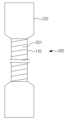
그래서, 종래에는 도 1 및 도 2에 도시된 바와 같이, 원통형 몸체(2a)와;, 상기 원통형 몸체(2a)보다 직경이 크도록 상기 원통형 몸체(2a)의 끝에 형성되어, 병변부위가 발생된 인체의 내강에 걸리는 확관부(2b)가 포함된 커버드 스텐트(2)를 제공하였다.So, conventionally, as shown in FIGS. 1 and 2, a cylindrical body (2a); formed at the end of the cylindrical body (2a) so that the diameter is larger than that of the cylindrical body (2a), the lesion site is generated A covered
여기서, 상기 원통형 몸체(2a)에는 PTFE 재질의 피막(2c)이 형성되었고, 확관부(2b)에는 PTFE 재질의 피막(2d) 또는 실리콘 재질의 피막(2e)이 형성되었다.Here, a
하지만, 종래의 경우에는 상기 확관부(2b)가 스텐트 전달 장치의 카테터에 압착되어 삽입되기 때문에, PTFE 재질의 특성상 피막(2d)이 늘어나는 문제가 발생하였다.However, in the conventional case, since the
그래서, 상기 병변부위에 커버드 스텐트(2) 시술 시, PTFE 재질의 특성상 늘어나게 되는 피막(2d)에 의해, 확관부(2b)가 원래의 형상으로 원상 복귀가 안되는 문제가 있었다.Therefore, when the covered
즉, 상기 확관부(2b)의 와이어의 탄성과, 늘어난 PTFE 재질의 피막(2d)의 탄성만으로는 복원력이 부족하여, 상기 확관부(2b)는 원상 복귀가 잘 안되었다.That is, the elasticity of the wire of the
이로 인해, 상기 확관부(2b)는 인체의 내강에 덜 걸리게 되면서, 인체의 흔들림 등과 같은 외력에 의해 상기 인체의 내강에서 미끄러져서 병변부위를 이탈하는 사례가 있었다.As a result, the
또한, 상기 확관부(2b)에 실리콘 재질의 피막(2e)이 형성된 커버드 스텐트(2)를 병변부위에 시술하면, 인체의 내강에서 발생된 체액에 상기 실리콘 재질의 피막(2e)이 접촉되면서 녹는 등의 훼손되는 문제가 발생하였다.In addition, when the covered
이러한 이유로, 상기 병변부위는 성장하면서 훼손된 실리콘 재질의 피막(2e)을 통해서 확관부(2b)의 공간부로 삽입되었고 이로 인해, 성장한 상기 병변부위에 의해 커버드 스텐트(2)의 내부가 막힐 우려가 있을 뿐만 아니라, 성장한 상기 병변부위가 확관부(2b)의 공간부에 걸려서, 일정기간이 지난 뒤 스텐트를 교체시술 또는 제거할 때에 커버드 스텐트(2)를 인체의 내강에서 제거하기가 어려워지는 우려가 있었다.For this reason, the lesion site was inserted into the space of the
이에 본 발명은, 병변부위에 시술 시 스텐트 전달 장치의 카테터에 의해 압착되어 있던 확관부가, 피막의 탄성에 의해 종래보다 용이하게 원상 복귀되어 인체의 내강에 걸리게 해주는 커버드 스텐트의 제조 방법과 그에 의해 제조된 커버드 스텐트를 제공하는데 목적이 있다.Accordingly, the present invention provides a method for manufacturing a covered stent in which an expanded tube compressed by a catheter of a stent delivery device during surgery on a lesion site is more easily returned to its original state than before due to the elasticity of the film and is caught in the lumen of the human body, and thereby It is an object of the present invention to provide a covered stent manufactured by
또한, 본 발명은 확관부에 형성된 피막이 인체의 내강에서 발생된 체액에 의해 녹는 것을 막아주는 커버드 스텐트의 제조 방법과 그에 의해 제조된 커버드 스텐트를 제공하는데 목적이 있다.In addition, an object of the present invention is to provide a method for manufacturing a covered stent that prevents a film formed on an expansion tube from being melted by bodily fluid generated in a lumen of a human body, and a covered stent manufactured thereby.
상기한 목적을 달성하기 위하여 본 발명은, 원통형 몸체 및, 원통형 몸체의 한쪽 끝 또는 양쪽 끝에 형성되는 원통형 몸체보다 직경이 큰 확관부가 포함된 지그에서, 원통형 몸체의 외면에 제1 PTFE 테이프를 감는 테이핑 작업을 행하는 과정;, 원통형 몸체 및, 원통형 몸체의 한쪽 끝 또는 양쪽 끝에 형성되는 원통형 몸체보다 직경이 큰 확관부가 포함된 스텐트의 내부에 지그를 끼운 후, 원통형 몸체 및 확관부의 외면에 제2 PTFE 테이프를 감는 테이핑 작업을 행하는 과정;, 지그가 내부에 끼워진 스텐트를 오븐에 넣어서 제1,2 PTFE 테이프가 서로 접착될 상태가 되도록 가열한 후, 오븐에서 빼내는 과정;, 가열된 제1,2 PTFE 테이프가 각각 감겨진 지그 및 스텐트를 지그의 일부와 동일한 형태로 형성된 하부 탄성부재의 제1끼움부에 끼운 후, 지그의 나머지 일부와 동일한 형태로 형성된 상부 탄성부재의 제1끼움부에 끼우는 과정;, 하부 탄성부재 및 상부 탄성부재를 하부 탄성부재 및 상부 탄성부재와 동일한 형태로 형성된 금형의 제1끼움부에 끼운 후, 상부 탄성부재를 가압부재로 가압하여, 제1,2 PTFE 테이프를 서로 접착시켜 공간부를 메워서 스텐트의 원통형 몸체에 제1피막을 형성하는 과정;, 가압부재의 가압을 해제하면서 금형의 제1끼움부에서 하부 탄성부재 및 상부 탄성부재를 빼내고, 하부 탄성부재의 제1끼움부와 상부 탄성부재의 제1끼움부에서 스텐트를 빼낸 후, 스텐트에서 지그를 제거하는 과정;, 확관부에 고정되지 않은 제2 PTFE 테이프를 원통형 몸체를 향해 뒤집어서 확관부를 노출시킨 후, 실리콘 코팅으로 확관부에 실리콘 코팅층을 형성하여 공간부를 메우는 과정;, 제2 PTFE 테이프를 확관부를 감싸도록 원상 복귀시킨 후, 확관부의 공간부 및 제2 PTFE 테이프 및 실리콘 코팅층을 연결사로 꿰매어 연결하여 스텐트의 확관부에 제2피막을 형성하는 과정으로 제조하는 것을 특징으로 하는 커버드 스텐트의 제조 방법과 그에 의해 제조된 커버드 스텐트를 제공한다.In order to achieve the above object, the present invention, in a jig including a cylindrical body and an expansion tube having a larger diameter than the cylindrical body formed at one end or both ends of the cylindrical body, a first PTFE tape is wound on the outer surface of the cylindrical body A process of performing a taping operation; After inserting a jig into the inside of a stent including a cylindrical body and an expanded tube having a larger diameter than the cylindrical body formed at one or both ends of the cylindrical body, the outer surface of the cylindrical body and the expanded tube is applied. 2 Process of performing a taping operation by winding a PTFE tape; A process of putting a stent with a jig inside into an oven and heating it so that the first and second PTFE tapes are bonded to each other, and then removing the stent from the oven; 2 Insert the jig and the stent, each of which has a PTFE tape, into the first fitting part of the lower elastic member formed in the same shape as a part of the jig, and then insert into the first fitting part of the upper elastic member formed in the same shape as the rest of the jig. Process; After inserting the lower elastic member and the upper elastic member into the first fitting part of the mold formed in the same shape as the lower elastic member and the upper elastic member, the upper elastic member is pressed with a pressing member to form the first and second PTFE tapes. The process of forming a first film on the cylindrical body of the stent by bonding to each other to fill the space; Taking out the lower elastic member and the upper elastic member from the first fitting part of the mold while releasing the pressure of the pressing member, and removing the lower elastic member After removing the stent from the first fitting part and the first fitting part of the upper elastic member, removing the jig from the stent; Turning the second PTFE tape, which is not fixed to the expansion part, toward the cylindrical body to expose the expansion part, Filling the space by forming a silicone coating layer on the expansion part with silicone coating; After returning the second PTFE tape to cover the expansion part, connecting the space of the expansion part, the second PTFE tape, and the silicone coating layer with a connecting thread Provided is a method for manufacturing a covered stent, characterized in that it is manufactured by a process of forming a second film on the expanded tube of the stent, and the covered stent manufactured thereby.
본 발명은 확관부의 공간부 및 제2 PTFE 테이프 및 실리콘 코팅층을 연결사로 꿰매어 연결하여, 스텐트의 확관부에 제2피막을 형성해주는 효과가 있다.The present invention has the effect of forming a second film on the expansion part of the stent by sewing and connecting the space part of the expansion tube, the second PTFE tape, and the silicone coating layer with a connecting thread.
즉, PTFE보다 탄성이 좋은 실리콘 코팅층에 의해, 스텐트의 확관부의 탄성이 상승하는 효과가 있다.That is, there is an effect of increasing the elasticity of the expansion section of the stent by the silicone coating layer having better elasticity than PTFE.
이로 인해, 병변부위에 시술 시 스텐트 전달 장치의 카테터에 의해 압착되어 있던 확관부가, 제2피막의 실리콘 코팅층의 탄성에 의해 종래보다 용이하게 원상 복귀되어 인체의 내강에 안정적으로 걸리게 되면서, 인체의 흔들림 등과 같은 외력에 의해 병변부위에서 미끄러져 이탈하는 것을 종래보다 막아주는 효과가 있다.As a result, the expansion tube, which was compressed by the catheter of the stent delivery device during surgery on the lesion site, is more easily returned to its original state than before by the elasticity of the silicone coating layer of the second film, and is stably caught in the lumen of the human body. There is an effect of preventing slipping and escaping from the lesion site by an external force such as shaking.
본 발명은 제2피막의 실리콘 코팅층을 대신하여 제2피막의 제2 PTFE 테이프가 인체의 내강에 접촉되는 효과가 있다.The present invention has the effect that the second PTFE tape of the second film contacts the lumen of the human body instead of the silicone coating layer of the second film.
즉, 확관부에 형성된 제2피막의 실리콘 코팅층이, 인체의 내강에서 발생된 체액에 의해 녹아서 훼손되는 것을 종래보다 막아주는 효과가 있다.That is, there is an effect of preventing the silicone coating layer of the second film formed on the expansion part from being melted and damaged by bodily fluid generated in the lumen of the human body.
이로 인해, 성장한 병변부위가 확관부의 공간부로 삽입되는 것을 막아서, 커버드 스텐트의 내부가 막히는 것을 막아주는 효과가 있다.Due to this, there is an effect of preventing the inside of the covered stent from being clogged by preventing the grown lesion from being inserted into the space of the expansion unit.
또한, 성장한 병변부위가 확관부의 공간부에 걸려서, 일정기간이 지난 뒤 스텐트를 교체시술 또는 제거할 때에 커버드 스텐트를 인체의 내강에서 제거하기가 어려워지는 것을 종래보다 막아주는 효과가 있다.In addition, there is an effect of preventing the grown lesion from being caught in the space of the expansion tube, which makes it difficult to remove the covered stent from the lumen of the human body when replacing or removing the stent after a certain period of time.
본 발명은 금형 및 가압부재를 통해 상,하부 탄성부재를 균일하게 가압하여, 제1,2 PTFE 테이프를 접착시킬 수 있는 효과가 있다.The present invention has an effect of bonding the first and second PTFE tapes by uniformly pressing the upper and lower elastic members through a mold and a pressing member.
즉, 제1,2 PTFE 테이프가 종래보다 골고루 접착되어 스텐트의 공간부를 메우기 때문에, 스텐트의 원통형 몸체에 제1피막이 안정적으로 형성되는 효과가 있다.That is, since the first and second PTFE tapes are more evenly adhered than before to fill the space of the stent, the first film is stably formed on the cylindrical body of the stent.
다시 말해, 스텐트의 원통형 몸체에서 PTFE 재질의 제1피막이 박리되는 것을 막아주는 효과가 있다.In other words, there is an effect of preventing the peeling of the first film made of PTFE from the cylindrical body of the stent.
이로 인해, 병변부위가 성장하여 원통형 몸체의 공간부로 삽입되는 것을 제1피막으로 막아주는 효과가 있다.Due to this, there is an effect of preventing the lesion portion from growing and being inserted into the space of the cylindrical body by the first film.
본 발명은 상,하부 탄성부재가 실리콘 또는 고무 재질로 이루어지기 때문에, 상,하부 탄성부재의 제조가 간편한 효과가 있다.According to the present invention, since the upper and lower elastic members are made of silicone or rubber, manufacturing of the upper and lower elastic members is simple.
본 발명은 지그 또는 상,하부 탄성부재에 손잡이가 형성되기 때문에, 오븐 및 상,하부 탄성부재 및 금형에 스텐트를 용이하게 이동시키거나 빼낼 수 있는 효과가 있다.In the present invention, since handles are formed on the jig or the upper and lower elastic members, there is an effect of easily moving or withdrawing the stent from the oven, the upper and lower elastic members, and the mold.
도 1 및 도 2는 종래의 커버드 스텐트를 보여주는 정면도,
도 3은 본 발명의 실시예에 사용되는 지그 및 스텐트의 다양한 형태를 보여주는 정면도,
도 4 내지 16은 본 발명의 실시예를 따른 커버드 스텐트의 제조 과정도,
도 17 및 도 18은 본 발명의 실시예를 따른 커버드 스텐트의 설치상태도,
도 19는 본 발명의 실시예의 다른 실시예를 따른 상,하부 탄성부재 및 금형의 평면도,
도 20은 본 발명의 실시예의 또 다른 실시예를 따른 상,하부 탄성부재 및 금형의 평면도이다.1 and 2 are front views showing a conventional covered stent;
3 is a front view showing various types of jigs and stents used in an embodiment of the present invention;
4 to 16 are manufacturing processes of a covered stent according to an embodiment of the present invention;
17 and 18 are installation states of a covered stent according to an embodiment of the present invention;
19 is a plan view of upper and lower elastic members and a mold according to another embodiment of the present invention;
20 is a plan view of upper and lower elastic members and a mold according to another embodiment of the present invention.
이에, 상기한 바와 같은 본 발명을 첨부도면에 의거하여 상세히 설명하면 다음과 같다.Accordingly, the present invention as described above will be described in detail based on the accompanying drawings.
도 3 내지 도 18에 도시된 바와 같이, 본 발명의 실시예를 따른 커버드 스텐트(1000)의 제조는 원통형 몸체(110) 및, 상기 원통형 몸체(110)의 한쪽 끝 또는 양쪽 끝에 형성되는 상기 원통형 몸체(110)보다 직경이 큰 확관부(120)가 포함된 지그(100)에서, 상기 원통형 몸체(110)의 외면에 제1 PTFE(polytetrafluoroethylene) 테이프(201)를 감는 테이핑 작업을 행한다.3 to 18, manufacturing of the covered
여기서, 상기 지그(100)의 확관부(120)는 도 3에 도시된 바와 같이 다양한 형태로 형성되며, 도 3에 도시된 형태와 다른 형태로도 형성될 수 있다.Here, the
또한, 상기 지그(100)는 금속 재질로 이루어지며, 제1 PTFE 테이프(201)는 지그(100)의 나선 방향으로만 감겨지거나, 상기 지그(100)의 원주 방향으로만 감겨지거나, 상기 지그(100)의 나선 및 원주 방향으로 섞여서 감겨진다.In addition, the
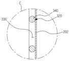
그리고, 원통형 몸체(310) 및, 상기 원통형 몸체(310)의 한쪽 끝 또는 양쪽 끝에 형성되는 상기 원통형 몸체(310)보다 직경이 큰 확관부(320)가 포함된 스텐트(300)의 내부에 지그(100)를 끼운 후, 상기 원통형 몸체(310) 및 확관부(320)의 외면에 제2 PTFE(polytetrafluoroethylene) 테이프(202)를 감는 테이핑 작업을 행한다. And, a jig inside the
여기서, 상기 스테트(300)의 원통형 몸체(310) 및 확관부(320)는 초탄성 형상기억합금으로 이루어진 적어도 하나 이상의 와이어(340)가 그물망 형태로 엮기거나 교차되어서 지그(100)가 내부에 끼워질 수 있는 중공식 형태로 형성되며, 다수의 공간부(330)가 외면에 형성된다.Here, the
또한, 상기 스텐트(300)의 확관부(320)는 도 3에 도시된 바와 같이 다양한 형태로 형성되며, 도 3에 도시된 형태와 다른 형태로도 형성될 수 있다.In addition, the
또한, 상기 제2 PTFE 테이프(202)는 스텐트(300)의 나선 방향으로만 감겨지거나, 상기 스텐트(300)의 원주 방향으로만 감겨지거나, 상기 스텐트(300)의 나선 및 원주 방향으로 섞여서 감겨진다.In addition, the
그리고, 상기 지그(100)가 내부에 끼워진 스텐트(300)를 오븐(400)에 넣어서 제1,2 PTFE(polytetrafluoroethylene) 테이프(201)(202)가 서로 접착될 상태가 되도록 가열한 후, 상기 오븐(400)에서 빼내는 과정을 행한다.Then, the
여기서, 상기 오븐(400)은 지그(100)가 내부에 끼워진 스텐트(300)를 300℃ 이상으로 가열하게 되며, 제1,2 PTFE 테이프(201)(202)는 상기 300℃ 이상의 가열에 의해 성질이 무르게 되면서 서로 접착될 상태가 된다.Here, the
그리고, 가열된 상기 제1,2 PTFE(polytetrafluoroethylene) 테이프(201)(202)가 각각 감겨진 지그(100) 및 스텐트(300)를 상기 지그(100)의 일부와 동일한 형태로 형성된 하부 탄성부재(500)의 제1끼움부(501)에 끼운 후, 상기 지그(20)의 나머지 일부와 동일한 형태로 형성된 상부 탄성부재(510)의 제1끼움부(511)에 끼우는 과정을 행한다.In addition, a lower elastic member formed in the same shape as a part of the
여기서, 상기 하부 탄성부재(500) 및 상부 탄성부재(510)는 실리콘 또는 고무 재질로 이루어지며, 힌지부재를 통해 서로 연결된다.Here, the lower
또한, 상기 하부 탄성부재(500)의 제1끼움부(501)와 상부 탄성부재(510)의 제1끼움부(511)는 스텐트(300)의 두께에 의해 변형되어 확장된다.In addition, the
그리고, 상기 하부 탄성부재(500) 및 상부 탄성부재(510)를 상기 하부 탄성부재(500) 및 상부 탄성부재(510)와 동일한 형태로 형성된 금형(600)의 제1끼움부(601)에 끼운 후, 상기 상부 탄성부재(510)를 가압부재(610)로 가압하여, 제1,2 PTFE(polytetrafluoroethylene) 테이프(201)(202)를 서로 접착시켜 공간부(330)를 메워서 스텐트(300)의 원통형 몸체(310)에 제1피막(200)을 형성하는 과정을 행한다.Then, the lower
여기서, 상기 스텐트(300)의 두께에 의해 제1끼움부(501)(511)가 변형되어 확장된 하부 탄성부재(500) 및 상부 탄성부재(510)는 금형(600)의 제1끼움부(601)와 가압부재(610)로부터 어느 한쪽으로 치우치지 않고 사방에서 균일하게 압력을 전달받게 된다.Here, the
또한, 상기 하부 탄성부재(500) 및 상부 탄성부재(510)는 금형(600)의 제1끼움부(601)와 가압부재(610)의 균일한 압력에 의해, 제1,2 PTFE 테이프(201)(202)가 각각 감겨진 지그(100) 및 스텐트(300)를 전체적으로 균일하게 가압하게 된다.In addition, the lower
또한, 상기 스텐트(300)의 와이어(340)에 밀착된 하부 탄성부재(500) 및 상부 탄성부재(510)의 일부는 변형되지 못하면서, 상기 스텐트(300)의 와이어(340)에 밀착되지 않은 하부 탄성부재(500) 및 상부 탄성부재(510)의 나머지 일부는 변형되어 공간부(330)로 삽입되면서 상기 스텐트(300)에 감겨진 제2 PTFE 테이프(202)를 가압하게 된다.In addition, while some of the lower
또한, 상기 스텐트(300)에 감겨진 제2 PTFE 테이프(202)는 하부 탄성부재(500) 및 상부 탄성부재(510)의 가압에 의해, 공간부(330)로 삽입되면서 원통형 몸체(110)에 감겨진 제1 PTFE 테이프(201)에 밀착되면서 접착된다.In addition, the
즉, 상기 공간부(330)가 메워지면서 스텐트(300)의 원통형 몸체(310)에 제1피막(200)이 형성된다.That is, the
또한, 상기 가압부재(610)는 유압 또는 공압에 작동되는 실린더(611)의 실린더로드에 연결되며, 상기 실린더(611)에 의해 상부 탄성부재(510)를 가압하게 된다.In addition, the pressing
또한, 상기 금형(600)은 제1끼움부(601)가 형성되도록 결합되는 적어도 2개 이상의 구성으로 이루어질 수도 있다.In addition, the
그리고, 상기 가압부재(610)의 가압을 해제하면서 금형(600)의 제1끼움부(601)에서 하부 탄성부재(500) 및 상부 탄성부재(510)를 빼내고, 상기 하부 탄성부재(500)의 제1끼움부(501)와 상부 탄성부재(510)의 제1끼움부(511)에서 스텐트(300)를 빼낸 후, 상기 스텐트(300)에서 지그(100)를 제거하는 과정을 행한다.In addition, the lower
여기서, 상기 가압부재(610)는 유압 또는 공압에 작동되는 실린더(611)에 의해 상부 탄성부재(510)를 가압 해제하게 된다.Here, the
또한, 상기 확관부(320)를 감싼 제2 PTFE(polytetrafluoroethylene) 테이프(202)는 상기 확관부(320)의 공간부(330)를 메우지 못하면서 상기 확관부(320)에 고정되지 않는다.In addition, the second polytetrafluoroethylene (PTFE)
또한, 상기 스텐트(300)에서 지그(100)를 제거하기 전에 열을 식히는 냉각 작업을 하게 된다.In addition, a cooling operation is performed to cool the heat before removing the
그리고, 상기 확관부(320)에 고정되지 않은 제2 PTFE(polytetrafluoroethylene) 테이프(202)를 원통형 몸체(310)를 향해 뒤집어서 상기 확관부(320)를 노출시킨 후, 실리콘 코팅으로 상기 확관부(320)에 실리콘 코팅층(203)을 형성하여 공간부(330)를 메우는 과정을 행한다.After exposing the
여기서, 상기 실리콘 코팅층(203)은 확관부(320)를 실리콘 용액에 넣거나, 상기 확관부(320)에 실리콘을 스프레이로 분사하여 형성한다.Here, the
또한, 상기 실리콘 코팅층(203)을 형성한 후에는 건조 작업을 하게 된다.In addition, after forming the
그리고, 상기 제2 PTFE(polytetrafluoroethylene) 테이프(202)를 확관부(320)를 감싸도록 원상 복귀시킨 후, 상기 확관부(320)의 공간부(330) 및 제2 PTFE(polytetrafluoroethylene) 테이프(202) 및 실리콘 코팅층(203)을 연결사(700)로 꿰매어 연결하여 스텐트(300)의 상기 확관부(320)에 제2피막(210)을 형성하는 과정을 행한다.Then, after returning the second polytetrafluoroethylene (PTFE)
즉, 상기 스텐트(300)의 원통형 몸체(310)에는 제1,2 PTFE(polytetrafluoroethylene) 테이프(201)(202)로 이루어진 의 제1피막(200)이 형성되고, 상기 스텐트(300)의 확관부(320)에는 제2 PTFE(polytetrafluoroethylene) 테이프(202) 및 실리콘 코팅층(203)으로 이루어진 제2피막(210)이 형성되면서, 본 발명의 실시예를 따른 상기 커버드 스텐트(1000)가 완성된다.That is, a
그래서, 도 17 및 도 18에 도시된 바와 같이, 상기 커버드 스텐트(1000)는 음식물, 담즙, 혈액 등이 지나가는 인체의 내강(1)에 스텐트 전달 장치를 통해 시술되어, 상기 인체의 내강(1)에 발생된 협착 또는 폐색되는 병변부위(1a)를 확장시켜주게 된다.Thus, as shown in FIGS. 17 and 18 , the covered
여기서, 상기 스텐트 전달 장치의 카테터에 의해 압착되어 있던 확관부(320)는 병변부위(1a)에 시술 시, 실리콘 코팅층(203)의 탄성에 의해 용이하게 원래의 형상으로 원상 복귀되어 인체의 내강(1)에 걸리게 된다.Here, the
또한, 상기 제2피막(210)의 제2 PTFE 테이프(202)는 인체의 내강(1)에서 발생된 체액이 실리콘 코팅층(203)에 접촉하는 것을 막게 된다.In addition, the
그리고, 도 19에 도시된 바와 같이, 본 발명의 실시예의 다른 실시예를 따른 상기 확관부(120)는 손잡이(130)가 외면에서 돌출 형성된다.And, as shown in FIG. 19, the
그래서, 가열된 상기 제1,2 PTFE(polytetrafluoroethylene) 테이프(201)(202)가 아닌, 손잡이(130)를 통해 오븐(400)에서 지그(100) 및 스텐트(300)를 빼낸다.Therefore, the
그리고, 상기 하부 탄성부재(500)와 상부 탄성부재(510)의 외면에는 제1끼움부(501)(511)와 각각 연결되며, 손잡이(130)가 끼워지는 제2끼움부(502)(512)를 각각 형성된다.In addition, the outer surfaces of the lower
또한, 상기 금형(600)의 외면에는 제1끼움부(601)와 연결되며, 손잡이(130)가 끼워지는 제2끼움부(602)가 형성된다.In addition, a second
그래서, 상기 손잡이(130)를 통해 금형(600)의 제1끼움부(601)에서 하부 탄성부재(500)와 상부 탄성부재(510)를 빼내고, 상기 손잡이(130)를 통해 하부 탄성부재(500)의 제1끼움부(501)와 상부 탄성부재(510)의 제1끼움부(511)에서 스텐트(300)를 빼낸다.So, take out the lower
그리고, 도 20에 도시된 바와 같이, 본 발명의 실시예의 또 다른 실시예를 따른 상기 하부 탄성부재(500)와 상부 탄성부재(510)는 손잡이(520)가 외면에서 돌출 형성된다.And, as shown in FIG. 20, the
여기서, 상기 손잡이(520)는 하부 탄성부재(500)와 상부 탄성부재(510)의 외면 한쪽 또는 양쪽에서 돌출 형성된다.Here, the
또한, 상기 금형(600)의 외면에는 제1끼움부(601)와 연결되며, 손잡이(520)가 끼워지는 제3끼움부(603)가 형성된다.In addition, a third
그래서, 상기 손잡이(520)를 통해 금형(600)의 제1끼움부(601)에서 하부 탄성부재(500)와 상부 탄성부재(510)를 빼낸다.Thus, the lower
이상에서는 본 발명을 특정의 바람직한 실시예를 예를 들어 도시하고 설명하였으나, 본 발명은 상기한 실시예에 한정되지 아니하며 본 발명의 정신을 벗어나지 않는 범위 내에서 당해 발명이 속하는 기술분야에서 통상의 지식을 가진자에 의해 다양한 변경과 수정이 가능할 것이다.In the above, the present invention has been shown and described as specific preferred embodiments, but the present invention is not limited to the above embodiments and is common knowledge in the art to which the present invention belongs within the scope of not departing from the spirit of the present invention. Various changes and modifications will be possible by the person who has it.
100 : 지그 110 : 원통형 몸체
120 : 확관부 130 : 손잡이
200 : 제1피막 201 : 제1 PTFE 테이프
202 : 제2 PTFE 테이프 203 : 실리콘 코팅층
210 : 제2피막 300 : 스텐트
310 : 원통형 몸체 320 : 확관부
330 : 공간부 340 : 와이어
400 : 오븐 500 : 하부 탄성부재
501 : 제1끼움부 502 : 제2끼움부
510 : 상부 탄성부재 511 : 제1끼움부
512 : 제2끼움부 520 : 손잡이
600 : 금형 601 : 제1끼움부
602 : 제2끼움부 603 : 제3끼움부
610 : 가압부재 611 : 실린더
700 : 연결사 1000 : 커버드 스텐트100: jig 110: cylindrical body
120: expansion part 130: handle
200: first film 201: first PTFE tape
202: second PTFE tape 203: silicone coating layer
210: second film 300: stent
310: cylindrical body 320: expansion pipe
330: space 340: wire
400: oven 500: lower elastic member
501: first fitting part 502: second fitting part
510: upper elastic member 511: first fitting part
512: second fitting part 520: handle
600: mold 601: first fitting part
602: second fitting part 603: third fitting part
610: pressing member 611: cylinder
700: connector 1000: covered stent
Claims (10)
Translated fromKorean원통형 몸체(110) 및, 상기 원통형 몸체(110)의 한쪽 끝 또는 양쪽 끝에 형성되는 상기 원통형 몸체(110)보다 직경이 큰 확관부(120)가 포함된 지그(100)에서, 상기 원통형 몸체(110)의 외면에 제1 PTFE(polytetrafluoroethylene) 테이프(201)를 감는 테이핑 작업을 행하는 과정;,
원통형 몸체(310) 및, 상기 원통형 몸체(310)의 한쪽 끝 또는 양쪽 끝에 형성되는 상기 원통형 몸체(310)보다 직경이 큰 확관부(320)가 포함된 스텐트(300)의 내부에 지그(100)를 끼운 후, 상기 원통형 몸체(310) 및 확관부(320)의 외면에 제2 PTFE(polytetrafluoroethylene) 테이프(202)를 감는 테이핑 작업을 행하는 과정;,
상기 지그(100)가 내부에 끼워진 스텐트(300)를 오븐(400)에 넣어서 제1,2 PTFE(polytetrafluoroethylene) 테이프(201)(202)가 서로 접착될 상태가 되도록 가열한 후, 상기 오븐(400)에서 빼내는 과정;,
가열된 상기 제1,2 PTFE(polytetrafluoroethylene) 테이프(201)(202)가 각각 감겨진 지그(100) 및 스텐트(300)를 상기 지그(100)의 일부와 동일한 형태로 형성된 하부 탄성부재(500)의 제1끼움부(501)에 끼운 후, 상기 지그(100)의 나머지 일부와 동일한 형태로 형성된 상부 탄성부재(510)의 제1끼움부(511)에 끼우는 과정;,
상기 하부 탄성부재(500) 및 상부 탄성부재(510)를 상기 하부 탄성부재(500) 및 상부 탄성부재(510)와 동일한 형태로 형성된 금형(600)의 제1끼움부(601)에 끼운 후, 상기 상부 탄성부재(510)를 가압부재(610)로 가압하여, 제1,2 PTFE(polytetrafluoroethylene) 테이프(201)(202)를 서로 접착시켜 공간부(330)를 메워서 스텐트(300)의 원통형 몸체(310)에 제1피막(200)을 형성하는 과정;,
상기 가압부재(610)의 가압을 해제하면서 금형(600)의 제1끼움부(601)에서 하부 탄성부재(500) 및 상부 탄성부재(510)를 빼내고, 상기 하부 탄성부재(500)의 제1끼움부(501)와 상부 탄성부재(510)의 제1끼움부(511)에서 스텐트(300)를 빼낸 후, 상기 스텐트(300)에서 지그(100)를 제거하는 과정;,
상기 확관부(320)에 고정되지 않은 제2 PTFE(polytetrafluoroethylene) 테이프(202)를 원통형 몸체(310)를 향해 뒤집어서 상기 확관부(320)를 노출시킨 후, 실리콘 코팅으로 상기 확관부(320)에 실리콘 코팅층(203)을 형성하여 공간부(330)를 메우는 과정;,
상기 제2 PTFE(polytetrafluoroethylene) 테이프(202)를 확관부(320)를 감싸도록 원상 복귀시킨 후, 상기 확관부(320)의 공간부(330) 및 제2 PTFE(polytetrafluoroethylene) 테이프(202) 및 실리콘 코팅층(203)을 연결사(700)로 꿰매어 연결하여 스텐트(300)의 상기 확관부(320)에 제2피막(210)을 형성하는 과정으로 제조하는 것을 특징으로 하는 커버드 스텐트의 제조 방법.In the manufacturing method of the covered stent,
In the jig 100 including the cylindrical body 110 and the expanded tube 120 having a larger diameter than the cylindrical body 110 formed at one end or both ends of the cylindrical body 110, the cylindrical body 110 ) Process of performing a taping operation of winding a first polytetrafluoroethylene (PTFE) tape 201 on the outer surface of the;,
A jig 100 inside the stent 300 including the cylindrical body 310 and the expanded tube 320 having a larger diameter than the cylindrical body 310 formed at one end or both ends of the cylindrical body 310 A process of performing a taping operation of winding a second polytetrafluoroethylene (PTFE) tape 202 around the outer surfaces of the cylindrical body 310 and the expansion tube 320 after inserting the;
After the stent 300 with the jig 100 inserted therein is put into an oven 400 and heated so that the first and second polytetrafluoroethylene (PTFE) tapes 201 and 202 are adhered to each other, the oven 400 ) in the process of subtracting;
A lower elastic member 500 formed of a jig 100 and a stent 300 around which the first and second polytetrafluoroethylene (PTFE) tapes 201 and 202 are wound, respectively, in the same shape as a part of the jig 100 A process of inserting into the first fitting part 501 of the upper elastic member 510 formed in the same shape as the rest of the jig 100;
After inserting the lower elastic member 500 and the upper elastic member 510 into the first fitting part 601 of the mold 600 formed in the same shape as the lower elastic member 500 and the upper elastic member 510, The upper elastic member 510 is pressurized by the pressing member 610, and the first and second polytetrafluoroethylene (PTFE) tapes 201 and 202 are adhered to each other to fill the space 330 to form a cylindrical shape of the stent 300. The process of forming the first film 200 on the body 310;
While releasing the pressure of the pressing member 610, take out the lower elastic member 500 and the upper elastic member 510 from the first fitting part 601 of the mold 600, and remove the first part of the lower elastic member 500. After taking out the stent 300 from the fitting part 501 and the first fitting part 511 of the upper elastic member 510, removing the jig 100 from the stent 300;
After exposing the expansion tube 320 by turning the second polytetrafluoroethylene (PTFE) tape 202 that is not fixed to the expansion tube 320 toward the cylindrical body 310, the expansion unit 320 is coated with silicone. A process of filling the space 330 by forming a silicone coating layer 203;
After the second polytetrafluoroethylene (PTFE) tape 202 is returned to its original state to cover the expansion tube 320, the space 330 of the expansion tube 320 and the second polytetrafluoroethylene (PTFE) tape 202 and silicone A method for manufacturing a covered stent, characterized in that the coating layer (203) is sewn and connected with a connecting thread (700) to form a second film (210) on the expanded tube (320) of the stent (300).
상기 하부 탄성부재(500) 및 상부 탄성부재(510)는 실리콘 또는 고무 재질로 이루어지는 것을 특징으로 하는 커버드 스텐트의 제조 방법.According to claim 1,
The method of manufacturing a covered stent, characterized in that the lower elastic member 500 and the upper elastic member 510 are made of silicone or rubber.
상기 가압부재(610)는 유압 또는 공압에 작동되는 실린더(611)에 의해 상부 탄성부재(510)를 가압 및 가압 해제하는 것을 특징으로 하는 커버드 스텐트의 제조 방법.According to claim 1,
The method of manufacturing a covered stent, characterized in that the pressure member 610 presses and releases the pressure on the upper elastic member 510 by means of a cylinder 611 operated by hydraulic pressure or pneumatic pressure.
상기 확관부(120)는 손잡이(130)를 외면에 형성하며,
상기 하부 탄성부재(500)와 상부 탄성부재(510)의 외면에는 제1끼움부(501)(511)와 각각 연결되며, 손잡이(130)가 끼워지는 제2끼움부(502)(512)를 각각 형성하고,
상기 금형(600)의 외면에는 제1끼움부(601)와 연결되며, 손잡이(130)가 끼워지는 제2끼움부(602)를 형성하는 것을 특징으로 하는 커버드 스텐트의 제조 방법.According to claim 1,
The expansion pipe 120 forms a handle 130 on the outer surface,
The outer surfaces of the lower elastic member 500 and the upper elastic member 510 are connected to the first fitting parts 501 and 511, respectively, and the second fitting parts 502 and 512 into which the handle 130 is fitted. form each
A method of manufacturing a covered stent, characterized in that forming a second fitting part 602 connected to the first fitting part 601 on the outer surface of the mold 600 and into which the handle 130 is fitted.
상기 하부 탄성부재(500)와 상부 탄성부재(510)는 손잡이(520)를 외면에 형성하며,
상기 금형(600)의 외면에는 제1끼움부(601)와 연결되며, 손잡이(520)가 끼워지는 제3끼움부(603)를 형성하는 것을 특징으로 하는 커버드 스텐트의 제조 방법.According to claim 1,
The lower elastic member 500 and the upper elastic member 510 form a handle 520 on the outer surface,
A method of manufacturing a covered stent, characterized in that forming a third fitting portion 603 connected to the first fitting portion 601 and into which a handle 520 is inserted on the outer surface of the mold 600.
원통형 몸체(110) 및, 상기 원통형 몸체(110)의 한쪽 끝 또는 양쪽 끝에 형성되는 상기 원통형 몸체(110)보다 직경이 큰 확관부(120)가 포함된 지그(100)에서, 상기 원통형 몸체(110)의 외면에 제1 PTFE(polytetrafluoroethylene) 테이프(201)를 감는 테이핑 작업을 행하는 과정;,
원통형 몸체(310) 및, 상기 원통형 몸체(310)의 한쪽 끝 또는 양쪽 끝에 형성되는 상기 원통형 몸체(310)보다 직경이 큰 확관부(320)가 포함된 스텐트(300)의 내부에 지그(100)를 끼운 후, 상기 원통형 몸체(310) 및 확관부(320)의 외면에 제2 PTFE(polytetrafluoroethylene) 테이프(202)를 감는 테이핑 작업을 행하는 과정;,
상기 지그(100)가 내부에 끼워진 스텐트(300)를 오븐(400)에 넣어서 제1,2 PTFE(polytetrafluoroethylene) 테이프(201)(202)가 서로 접착될 상태가 되도록 가열한 후, 상기 오븐(400)에서 빼내는 과정;,
가열된 상기 제1,2 PTFE(polytetrafluoroethylene) 테이프(201)(202)가 각각 감겨진 지그(100) 및 스텐트(300)를 상기 지그(100)의 일부와 동일한 형태로 형성된 하부 탄성부재(500)의 제1끼움부(501)에 끼운 후, 상기 지그(100)의 나머지 일부와 동일한 형태로 형성된 상부 탄성부재(510)의 제1끼움부(511)에 끼우는 과정;,
상기 하부 탄성부재(500) 및 상부 탄성부재(510)를 상기 하부 탄성부재(500) 및 상부 탄성부재(510)와 동일한 형태로 형성된 금형(600)의 제1끼움부(601)에 끼운 후, 상기 상부 탄성부재(510)를 가압부재(610)로 가압하여, 제1,2 PTFE(polytetrafluoroethylene) 테이프(201)(202)를 서로 접착시켜 공간부(330)를 메워서 스텐트(300)의 원통형 몸체(310)에 제1피막(200)을 형성하는 과정;,
상기 가압부재(610)의 가압을 해제하면서 금형(600)의 제1끼움부(601)에서 하부 탄성부재(500) 및 상부 탄성부재(510)를 빼내고, 상기 하부 탄성부재(500)의 제1끼움부(501)와 상부 탄성부재(510)의 제1끼움부(511)에서 스텐트(300)를 빼낸 후, 상기 스텐트(300)에서 지그(100)를 제거하는 과정;,
상기 확관부(320)에 고정되지 않은 제2 PTFE(polytetrafluoroethylene) 테이프(202)를 원통형 몸체(310)를 향해 뒤집어서 상기 확관부(320)를 노출시킨 후, 실리콘 코팅으로 상기 확관부(320)에 실리콘 코팅층(203)을 형성하여 공간부(330)를 메우는 과정;,
상기 제2 PTFE(polytetrafluoroethylene) 테이프(202)를 확관부(320)를 감싸도록 원상 복귀시킨 후, 상기 확관부(320)의 공간부(330) 및 제2 PTFE(polytetrafluoroethylene) 테이프(202) 및 실리콘 코팅층(203)을 연결사(700)로 꿰매어 연결하여 스텐트(300)의 상기 확관부(320)에 제2피막(210)을 형성하는 과정을 통하여 제조한 것을 특징으로 하는 커버드 스텐트.In the covered stent,
In the jig 100 including the cylindrical body 110 and the expanded tube 120 having a larger diameter than the cylindrical body 110 formed at one end or both ends of the cylindrical body 110, the cylindrical body 110 ) A process of performing a taping operation of winding a first PTFE (polytetrafluoroethylene) tape 201 on the outer surface of the;,
A jig 100 inside the stent 300 including the cylindrical body 310 and the expanded tube 320 having a larger diameter than the cylindrical body 310 formed at one end or both ends of the cylindrical body 310 A process of performing a taping operation of winding a second polytetrafluoroethylene (PTFE) tape 202 around the outer surfaces of the cylindrical body 310 and the expansion tube 320 after inserting the;
After the stent 300 with the jig 100 inserted therein is put into an oven 400 and heated so that the first and second polytetrafluoroethylene (PTFE) tapes 201 and 202 are adhered to each other, the oven 400 ) in the process of subtracting;
A lower elastic member 500 formed of a jig 100 and a stent 300 around which the first and second polytetrafluoroethylene (PTFE) tapes 201 and 202 are wound, respectively, in the same shape as a part of the jig 100 A process of inserting into the first fitting part 501 of the upper elastic member 510 formed in the same shape as the rest of the jig 100;
After inserting the lower elastic member 500 and the upper elastic member 510 into the first fitting part 601 of the mold 600 formed in the same shape as the lower elastic member 500 and the upper elastic member 510, The upper elastic member 510 is pressurized by the pressing member 610, and the first and second polytetrafluoroethylene (PTFE) tapes 201 and 202 are adhered to each other to fill the space 330 to form a cylindrical shape of the stent 300. The process of forming the first film 200 on the body 310;,
The lower elastic member 500 and the upper elastic member 510 are removed from the first fitting part 601 of the mold 600 while releasing the pressure of the pressing member 610, and the first part of the lower elastic member 500 is removed. After taking out the stent 300 from the fitting part 501 and the first fitting part 511 of the upper elastic member 510, removing the jig 100 from the stent 300;
After exposing the expansion tube 320 by turning the second polytetrafluoroethylene (PTFE) tape 202 that is not fixed to the expansion tube 320 toward the cylindrical body 310, the expansion tube 320 is coated with silicone. A process of filling the space 330 by forming a silicone coating layer 203;
After the second polytetrafluoroethylene (PTFE) tape 202 is returned to its original state to cover the expansion tube 320, the space 330 of the expansion tube 320 and the second polytetrafluoroethylene (PTFE) tape 202 and silicone A covered stent characterized in that it is manufactured through a process of forming a second film 210 on the expansion part 320 of the stent 300 by sewing and connecting the coating layer 203 with a connecting thread 700.
상기 하부 탄성부재(500) 및 상부 탄성부재(510)는 실리콘 또는 고무 재질로 이루어지는 것을 특징으로 하는 커버드 스텐트.According to claim 6,
The lower elastic member 500 and the upper elastic member 510 are covered stents, characterized in that made of silicone or rubber material.
상기 가압부재(610)는 유압 또는 공압에 작동되는 실린더(611)에 의해 상부 탄성부재(510)를 가압 및 가압 해제하는 것을 특징으로 하는 커버드 스텐트.According to claim 6,
The pressure member 610 is a covered stent, characterized in that the upper elastic member 510 is pressed and released by a cylinder 611 operated by hydraulic pressure or pneumatic pressure.
상기 확관부(120)는 손잡이(130)를 외면에 형성하며,
상기 하부 탄성부재(500)와 상부 탄성부재(510)의 외면에는 제1끼움부(501)(511)와 각각 연결되며, 손잡이(130)가 끼워지는 제2끼움부(502)(512)를 각각 형성하고,
상기 금형(600)의 외면에는 제1끼움부(601)와 연결되며, 손잡이(130)가 끼워지는 제2끼움부(602)를 형성하는 것을 특징으로 하는 커버드 스텐트.According to claim 6,
The expansion pipe 120 forms a handle 130 on the outer surface,
The outer surfaces of the lower elastic member 500 and the upper elastic member 510 are connected to the first fitting parts 501 and 511, respectively, and the second fitting parts 502 and 512 into which the handle 130 is fitted. form each
A covered stent characterized in that a second fitting part 602 connected to the first fitting part 601 and into which the handle 130 is inserted is formed on the outer surface of the mold 600.
상기 하부 탄성부재(500)와 상부 탄성부재(510)는 손잡이(520)를 외면에 형성하며,
상기 금형(600)의 외면에는 제1끼움부(601)와 연결되며, 손잡이(520)가 끼워지는 제3끼움부(603)를 형성하는 것을 특징으로 하는 커버드 스텐트.According to claim 6,
The lower elastic member 500 and the upper elastic member 510 form a handle 520 on the outer surface,
A covered stent characterized in that a third fitting portion 603 connected to the first fitting portion 601 and into which a handle 520 is fitted is formed on the outer surface of the mold 600.
Priority Applications (3)
| Application Number | Priority Date | Filing Date | Title |
|---|---|---|---|
| KR1020210064307AKR102535728B1 (en) | 2021-05-18 | 2021-05-18 | Manufactured method of a covered stent and a covered stent by manufactured method thereof |
| US17/394,303US20220371259A1 (en) | 2021-05-18 | 2021-08-04 | Method of manufacturing covered stent and covered stent manufactured thereby |
| JP2021130983AJP7246768B2 (en) | 2021-05-18 | 2021-08-10 | Covered stent manufacturing method and covered stent manufactured by the method |
Applications Claiming Priority (1)
| Application Number | Priority Date | Filing Date | Title |
|---|---|---|---|
| KR1020210064307AKR102535728B1 (en) | 2021-05-18 | 2021-05-18 | Manufactured method of a covered stent and a covered stent by manufactured method thereof |
Publications (2)
| Publication Number | Publication Date |
|---|---|
| KR20220156709A KR20220156709A (en) | 2022-11-28 |
| KR102535728B1true KR102535728B1 (en) | 2023-05-30 |
Family
ID=84104236
Family Applications (1)
| Application Number | Title | Priority Date | Filing Date |
|---|---|---|---|
| KR1020210064307AActiveKR102535728B1 (en) | 2021-05-18 | 2021-05-18 | Manufactured method of a covered stent and a covered stent by manufactured method thereof |
Country Status (3)
| Country | Link |
|---|---|
| US (1) | US20220371259A1 (en) |
| JP (1) | JP7246768B2 (en) |
| KR (1) | KR102535728B1 (en) |
Families Citing this family (1)
| Publication number | Priority date | Publication date | Assignee | Title |
|---|---|---|---|---|
| WO2025015000A1 (en)* | 2023-07-10 | 2025-01-16 | Atrium Medical Corporation | Compressed stent with flexible covering |
Citations (1)
| Publication number | Priority date | Publication date | Assignee | Title |
|---|---|---|---|---|
| KR101557010B1 (en) | 2014-07-11 | 2015-10-02 | 주식회사 비씨엠 | A Covered Stents and the making Methods for a Covered Stent |
Family Cites Families (19)
| Publication number | Priority date | Publication date | Assignee | Title |
|---|---|---|---|---|
| US5078726A (en)* | 1989-02-01 | 1992-01-07 | Kreamer Jeffry W | Graft stent and method of repairing blood vessels |
| US5735892A (en)* | 1993-08-18 | 1998-04-07 | W. L. Gore & Associates, Inc. | Intraluminal stent graft |
| US6475232B1 (en)* | 1996-12-10 | 2002-11-05 | Purdue Research Foundation | Stent with reduced thrombogenicity |
| JP3507503B2 (en)* | 1995-03-10 | 2004-03-15 | インプラ・インコーポレーテッド | Sealable stent for body cavity, method for producing the same, and method for introducing the same into body cavity |
| US7118592B1 (en)* | 2000-09-12 | 2006-10-10 | Advanced Cardiovascular Systems, Inc. | Covered stent assembly for reduced-shortening during stent expansion |
| KR100442330B1 (en)* | 2002-09-03 | 2004-07-30 | 주식회사 엠아이텍 | Stent and manufacturing method the same |
| US20050060020A1 (en)* | 2003-09-17 | 2005-03-17 | Scimed Life Systems, Inc. | Covered stent with biologically active material |
| US8998973B2 (en)* | 2004-03-02 | 2015-04-07 | Boston Scientific Scimed, Inc. | Medical devices including metallic films |
| JP2005278993A (en)* | 2004-03-30 | 2005-10-13 | Terumo Corp | Stent for indwelling in living body, and production method of the same |
| US8696733B2 (en)* | 2006-08-29 | 2014-04-15 | C. R. Bard, Inc. | Helical high fatigue stent-graft |
| KR100988816B1 (en)* | 2008-01-29 | 2010-10-20 | 신경민 | Double Encapsulated Stent for Bile Ducts |
| KR101006990B1 (en)* | 2009-02-09 | 2011-01-12 | 신경민 | Flexural grease coated stent that can maintain flexure and its manufacturing method |
| KR101160646B1 (en)* | 2010-05-14 | 2012-06-29 | 신경민 | Abstinence-only stent on the prevention of food emissions |
| US10034740B2 (en)* | 2010-06-28 | 2018-07-31 | Cook Medical Technologies Llc | Covered stent |
| JP2013223540A (en)* | 2012-04-19 | 2013-10-31 | Terumo Corp | Stent covering method |
| KR20150052719A (en)* | 2013-11-06 | 2015-05-14 | 주식회사 비씨엠 | A making methods for stent graft and the stent graft thereof |
| KR101657648B1 (en) | 2014-10-21 | 2016-09-19 | (주) 태웅메디칼 | Manufacturing methods for anti-migration stent and the anti-migration stent thereof |
| GB201521474D0 (en)* | 2015-12-04 | 2016-01-20 | Univ Manchester | Textured surfaces for implants |
| US20170340460A1 (en)* | 2016-05-31 | 2017-11-30 | V-Wave Ltd. | Systems and methods for making encapsulated hourglass shaped stents |
- 2021
- 2021-05-18KRKR1020210064307Apatent/KR102535728B1/enactiveActive
- 2021-08-04USUS17/394,303patent/US20220371259A1/enactivePending
- 2021-08-10JPJP2021130983Apatent/JP7246768B2/enactiveActive
Patent Citations (1)
| Publication number | Priority date | Publication date | Assignee | Title |
|---|---|---|---|---|
| KR101557010B1 (en) | 2014-07-11 | 2015-10-02 | 주식회사 비씨엠 | A Covered Stents and the making Methods for a Covered Stent |
Also Published As
| Publication number | Publication date |
|---|---|
| JP2022177774A (en) | 2022-12-01 |
| JP7246768B2 (en) | 2023-03-28 |
| KR20220156709A (en) | 2022-11-28 |
| US20220371259A1 (en) | 2022-11-24 |
Similar Documents
| Publication | Publication Date | Title |
|---|---|---|
| KR102535715B1 (en) | Method of forming a PTFE film on a stent, and a stent manufactured by the method and a jig used for the method | |
| JP5623904B2 (en) | Side branching intraluminal prosthesis and method of delivery | |
| US6863683B2 (en) | Cold-molding process for loading a stent onto a stent delivery system | |
| US6024737A (en) | Stent crimping device | |
| US9956069B2 (en) | Composite prosthesis with external polymeric support structure and methods of manufacturing the same | |
| US7743481B2 (en) | Stent crimping | |
| US20170296325A1 (en) | Stent-graft prosthesis and method of manufacture | |
| US20170360584A1 (en) | Apparatus and methods for conduits and materials | |
| US20090221967A1 (en) | Intravascular Device | |
| KR102535728B1 (en) | Manufactured method of a covered stent and a covered stent by manufactured method thereof | |
| JP2015503364A5 (en) | ||
| KR20080002985A (en) | Internal cannulated joint for medical delivery systems | |
| US20110264056A1 (en) | Catheter tip assembly | |
| CN104884004B (en) | The pressure of bioresorbable support holds method | |
| CN104644293B (en) | A kind of pressure of intravascular stent holds method and pressure holds structure | |
| JP2021053005A (en) | Balloon catheter, and manufacturing method of balloon | |
| JP5822290B2 (en) | Method for manufacturing catheter tube | |
| JP7556158B2 (en) | Flexible and stretch-resistant long shaft | |
| EP3903730B1 (en) | Covered stent | |
| JP7641382B2 (en) | Stent graft and method for manufacturing the same | |
| WO2013121726A1 (en) | Covered stent | |
| JP2020044292A (en) | Gastrointestinal stent | |
| JP2018171170A (en) | Method for manufacturing stent delivery catheter and method for manufacturing reduced diameter stent | |
| JPH02274259A (en) | Method for manufacturing braided reinforced catheter |
Legal Events
| Date | Code | Title | Description |
|---|---|---|---|
| PA0109 | Patent application | Patent event code:PA01091R01D Comment text:Patent Application Patent event date:20210518 | |
| PA0201 | Request for examination | ||
| PG1501 | Laying open of application | ||
| E701 | Decision to grant or registration of patent right | ||
| PE0701 | Decision of registration | Patent event code:PE07011S01D Comment text:Decision to Grant Registration Patent event date:20230405 | |
| GRNT | Written decision to grant | ||
| PR0701 | Registration of establishment | Comment text:Registration of Establishment Patent event date:20230518 Patent event code:PR07011E01D | |
| PR1002 | Payment of registration fee | Payment date:20230518 End annual number:3 Start annual number:1 | |
| PG1601 | Publication of registration |