KR102535433B1 - Instrument with a multistream instrument head for argon plasma coagulation - Google Patents
Instrument with a multistream instrument head for argon plasma coagulationDownload PDFInfo
- Publication number
- KR102535433B1 KR102535433B1KR1020180064223AKR20180064223AKR102535433B1KR 102535433 B1KR102535433 B1KR 102535433B1KR 1020180064223 AKR1020180064223 AKR 1020180064223AKR 20180064223 AKR20180064223 AKR 20180064223AKR 102535433 B1KR102535433 B1KR 102535433B1
- Authority
- KR
- South Korea
- Prior art keywords
- opening
- primary stream
- instrument
- gas
- channel section
- Prior art date
- Legal status (The legal status is an assumption and is not a legal conclusion. Google has not performed a legal analysis and makes no representation as to the accuracy of the status listed.)
- Active
Links
Images


Classifications
- A—HUMAN NECESSITIES
- A61—MEDICAL OR VETERINARY SCIENCE; HYGIENE
- A61B—DIAGNOSIS; SURGERY; IDENTIFICATION
- A61B18/00—Surgical instruments, devices or methods for transferring non-mechanical forms of energy to or from the body
- A61B18/04—Surgical instruments, devices or methods for transferring non-mechanical forms of energy to or from the body by heating
- A61B18/042—Surgical instruments, devices or methods for transferring non-mechanical forms of energy to or from the body by heating using additional gas becoming plasma
- A—HUMAN NECESSITIES
- A61—MEDICAL OR VETERINARY SCIENCE; HYGIENE
- A61B—DIAGNOSIS; SURGERY; IDENTIFICATION
- A61B18/00—Surgical instruments, devices or methods for transferring non-mechanical forms of energy to or from the body
- H—ELECTRICITY
- H05—ELECTRIC TECHNIQUES NOT OTHERWISE PROVIDED FOR
- H05H—PLASMA TECHNIQUE; PRODUCTION OF ACCELERATED ELECTRICALLY-CHARGED PARTICLES OR OF NEUTRONS; PRODUCTION OR ACCELERATION OF NEUTRAL MOLECULAR OR ATOMIC BEAMS
- H05H1/00—Generating plasma; Handling plasma
- H05H1/24—Generating plasma
- H05H1/46—Generating plasma using applied electromagnetic fields, e.g. high frequency or microwave energy
- A—HUMAN NECESSITIES
- A61—MEDICAL OR VETERINARY SCIENCE; HYGIENE
- A61B—DIAGNOSIS; SURGERY; IDENTIFICATION
- A61B18/00—Surgical instruments, devices or methods for transferring non-mechanical forms of energy to or from the body
- A61B18/04—Surgical instruments, devices or methods for transferring non-mechanical forms of energy to or from the body by heating
- A61B18/08—Surgical instruments, devices or methods for transferring non-mechanical forms of energy to or from the body by heating by means of electrically-heated probes
- A61B18/082—Probes or electrodes therefor
- A—HUMAN NECESSITIES
- A61—MEDICAL OR VETERINARY SCIENCE; HYGIENE
- A61B—DIAGNOSIS; SURGERY; IDENTIFICATION
- A61B17/00—Surgical instruments, devices or methods
- A61B2017/00477—Coupling
- A—HUMAN NECESSITIES
- A61—MEDICAL OR VETERINARY SCIENCE; HYGIENE
- A61B—DIAGNOSIS; SURGERY; IDENTIFICATION
- A61B18/00—Surgical instruments, devices or methods for transferring non-mechanical forms of energy to or from the body
- A61B2018/00571—Surgical instruments, devices or methods for transferring non-mechanical forms of energy to or from the body for achieving a particular surgical effect
- A61B2018/00577—Ablation
- A61B2018/00583—Coblation, i.e. ablation using a cold plasma
- A—HUMAN NECESSITIES
- A61—MEDICAL OR VETERINARY SCIENCE; HYGIENE
- A61B—DIAGNOSIS; SURGERY; IDENTIFICATION
- A61B18/00—Surgical instruments, devices or methods for transferring non-mechanical forms of energy to or from the body
- A61B2018/00571—Surgical instruments, devices or methods for transferring non-mechanical forms of energy to or from the body for achieving a particular surgical effect
- A61B2018/00589—Coagulation
- A—HUMAN NECESSITIES
- A61—MEDICAL OR VETERINARY SCIENCE; HYGIENE
- A61B—DIAGNOSIS; SURGERY; IDENTIFICATION
- A61B18/00—Surgical instruments, devices or methods for transferring non-mechanical forms of energy to or from the body
- A61B2018/00636—Sensing and controlling the application of energy
- A61B2018/00696—Controlled or regulated parameters
- A61B2018/00744—Fluid flow
- A—HUMAN NECESSITIES
- A61—MEDICAL OR VETERINARY SCIENCE; HYGIENE
- A61B—DIAGNOSIS; SURGERY; IDENTIFICATION
- A61B18/00—Surgical instruments, devices or methods for transferring non-mechanical forms of energy to or from the body
- A61B2018/00964—Features of probes
- A—HUMAN NECESSITIES
- A61—MEDICAL OR VETERINARY SCIENCE; HYGIENE
- A61B—DIAGNOSIS; SURGERY; IDENTIFICATION
- A61B18/00—Surgical instruments, devices or methods for transferring non-mechanical forms of energy to or from the body
- A61B2018/00982—Surgical instruments, devices or methods for transferring non-mechanical forms of energy to or from the body combined with or comprising means for visual or photographic inspections inside the body, e.g. endoscopes
- A—HUMAN NECESSITIES
- A61—MEDICAL OR VETERINARY SCIENCE; HYGIENE
- A61B—DIAGNOSIS; SURGERY; IDENTIFICATION
- A61B18/00—Surgical instruments, devices or methods for transferring non-mechanical forms of energy to or from the body
- A61B18/04—Surgical instruments, devices or methods for transferring non-mechanical forms of energy to or from the body by heating
- A61B2018/044—Surgical instruments, devices or methods for transferring non-mechanical forms of energy to or from the body by heating the surgical action being effected by a circulating hot fluid
- A61B2018/048—Surgical instruments, devices or methods for transferring non-mechanical forms of energy to or from the body by heating the surgical action being effected by a circulating hot fluid in gaseous form
- A—HUMAN NECESSITIES
- A61—MEDICAL OR VETERINARY SCIENCE; HYGIENE
- A61B—DIAGNOSIS; SURGERY; IDENTIFICATION
- A61B18/00—Surgical instruments, devices or methods for transferring non-mechanical forms of energy to or from the body
- A61B18/04—Surgical instruments, devices or methods for transferring non-mechanical forms of energy to or from the body by heating
- A61B18/12—Surgical instruments, devices or methods for transferring non-mechanical forms of energy to or from the body by heating by passing a current through the tissue to be heated, e.g. high-frequency current
- A61B18/1206—Generators therefor
- A61B2018/1246—Generators therefor characterised by the output polarity
- A61B2018/1253—Generators therefor characterised by the output polarity monopolar
- A—HUMAN NECESSITIES
- A61—MEDICAL OR VETERINARY SCIENCE; HYGIENE
- A61B—DIAGNOSIS; SURGERY; IDENTIFICATION
- A61B2218/00—Details of surgical instruments, devices or methods for transferring non-mechanical forms of energy to or from the body
- A61B2218/001—Details of surgical instruments, devices or methods for transferring non-mechanical forms of energy to or from the body having means for irrigation and/or aspiration of substances to and/or from the surgical site
- A61B2218/002—Irrigation
- A61B2218/005—Irrigation using gas or vapor, e.g. for protection or purging
- H—ELECTRICITY
- H05—ELECTRIC TECHNIQUES NOT OTHERWISE PROVIDED FOR
- H05H—PLASMA TECHNIQUE; PRODUCTION OF ACCELERATED ELECTRICALLY-CHARGED PARTICLES OR OF NEUTRONS; PRODUCTION OR ACCELERATION OF NEUTRAL MOLECULAR OR ATOMIC BEAMS
- H05H1/00—Generating plasma; Handling plasma
- H05H1/24—Generating plasma
- H05H1/46—Generating plasma using applied electromagnetic fields, e.g. high frequency or microwave energy
- H05H1/4645—Radiofrequency discharges
Landscapes
- Health & Medical Sciences (AREA)
- Engineering & Computer Science (AREA)
- Surgery (AREA)
- Life Sciences & Earth Sciences (AREA)
- Physics & Mathematics (AREA)
- Plasma & Fusion (AREA)
- Medical Informatics (AREA)
- Heart & Thoracic Surgery (AREA)
- Biomedical Technology (AREA)
- Molecular Biology (AREA)
- Animal Behavior & Ethology (AREA)
- General Health & Medical Sciences (AREA)
- Public Health (AREA)
- Veterinary Medicine (AREA)
- Otolaryngology (AREA)
- Nuclear Medicine, Radiotherapy & Molecular Imaging (AREA)
- Electromagnetism (AREA)
- Spectroscopy & Molecular Physics (AREA)
- Surgical Instruments (AREA)
Abstract
Translated fromKoreanDescription
Translated fromKorean본 발명은 아르곤 플라즈마 응고를 위한 기구에 관한 것이다.The present invention relates to an apparatus for argon plasma coagulation.
단극성 아르곤 플라즈마 응고(APC)에서, 기구의 원위 단부는 처리될 조직 근처로 이동하고, 이온화된 아르곤 가스는 기구의 원위 단부 상의 전극과 조직 표면 사이에서 점화되어, 플라즈마 빔이 그 결과로 형성된다. 플라즈마 빔의 사용으로, 기구의 원위 단부와 조직 사이의 접촉없이 열 조직 효과를 발생시키는 것이 가능하다. 특히, 조직을 파괴하거나 지혈을 달성하는 것이 가능하다. 점화 거리는 플라즈마의 성공적인 점화를 위해 기구가 조직을 향해 이동해야 하는 거리를 지칭한다.In monopolar argon plasma coagulation (APC), the distal end of the instrument is moved near the tissue to be treated and ionized argon gas is ignited between an electrode on the distal end of the instrument and the tissue surface, resulting in a plasma beam being formed . With the use of a plasma beam, it is possible to create a thermal tissue effect without contact between the distal end of the instrument and the tissue. In particular, it is possible to destroy tissue or achieve hemostasis. Ignition distance refers to the distance the instrument must travel toward the tissue for successful ignition of the plasma.
비록 더 큰 거리에서도 플라즈마의 신뢰성있는 점화를 보장하려면 큰 점화 거리가 바람직하다. 점화 거리는 또한 점화 거리, 예를 들어 작업 영역 내의 유체 또는 습기를 감소시키는 영향에서는 커야 한다. 기구의 원위 단부와 조직 사이의 거리가 변경되는 경우에도, 점화 거리가 길면 지속적인 치료가 가능하다. 이는 사용하는 동안 조직으로부터의 거리 및 국부적인 점화 조건이 크게 변할 수 있기 때문에 대 영역 조직 표면의 연속적인 APC 처리에 특히 유리하다. 큰 점화 거리를 갖는 기구가 플라즈마 점화를 위한 조건이 조직에 대한 기구의 큰 영역 내에서 이용 가능한 위치에 존재하기 때문에, 점화 거리가 큰 기구는 조직의 다른 섹션을 치료하는 동안 종종 조직에 대해 새롭게 재위치될 필요는 없다. 기구가 조직에 걸쳐 큰 거리로 인도되면, 대 영역 조직 영역이 동시에 플라즈마로 처리될 수 있다. 또한, 치료될 조직으로부터 기구의 원위 단부의 거리가 증가할수록, 예를 들어 기구가 설치될 수 있는 또는 안에 설치될 수 있는 내시경의 원위 단부 상의 영상 전송 장치에 의해, 절차 중에 치료할 조직에 대한 기구 사용자의 시야를 개선시킨다.A large ignition distance is desirable to ensure reliable ignition of the plasma even at larger distances. The ignition distance must also be large in the effect of reducing the ignition distance, eg fluid or moisture in the working area. Even when the distance between the distal end of the instrument and the tissue changes, a long ignition distance allows continuous treatment. This is particularly advantageous for continuous APC treatment of large-area tissue surfaces because distance from tissue and local ignition conditions can vary greatly during use. Because instruments with large firing distances exist at locations where conditions for plasma ignition are available within a large area of the instrument to tissue, instruments with large firing distances often regenerate tissue while treating different sections of tissue. need not be located. If the instrument is guided a large distance across the tissue, a large area tissue area can be treated with the plasma simultaneously. Also, as the distance of the distal end of the instrument from the tissue to be treated increases, for example by means of an image transmission device on the distal end of an endoscope into or into which the instrument can be installed, the user of the instrument relative to the tissue to be treated during the procedure. improve the field of view of
공지된 기구에서, 습기가 있거나 습한 환경에서 사용하는 것과 비교하여 건조한 환경에서 기구를 사용하면, 조직으로부터의 점화 거리가 현저하게 감소하고, 이는 - 점화를 위해 - 기구가 치료할 조직에 더 근접하게 이동해야 하는 결과가 얻어진다. 이러한 결과로 인하여, 단위 시간당 기구로 처리될 조직 표면(표면 성능)은 조직에 대한 기구의 보다 빈번하게 필요한 재배치로 인해 감소할 수 있다. 치료를 위해 요구되는 시간은 대응하게 증가된다. 또한, 치료 영역에 대한 명확한 관찰은 기구에 의해 발생된 음영 때문에 제한될 수 있다. 또한, 근접 거리에 있을 경우, 기구의 팁을 조직으로 오염시킬 확률이 증가한다.In known instruments, use of the instrument in a dry environment compared to use in a humid or damp environment significantly reduces the firing distance from the tissue, which - for ignition - moves the instrument closer to the tissue to be treated. The required result is obtained. As a result of this, the tissue surface (surface performance) to be treated with the instrument per unit time may decrease due to the more frequently required repositioning of the instrument relative to the tissue. The time required for treatment is correspondingly increased. Also, a clear view of the treatment area may be limited due to shadows created by the instrument. In addition, the probability of contaminating the tip of the instrument with tissue increases when in close proximity.
공보 DE 10 2005 021 304 A1 호에는, 아르곤 플라즈마 응고를 위한 내시경 수술 장치가 공지되어 있으며, 상기 장치는 내시경에 삽입될 수 있는 작동 조립체를 포함하고, 전극이 배치되고 불활성 가스가 통과하여 조직에 공급될 수 있는 제 1 채널을 가진다. 작동 조립체는 제 2 채널도 가진다. 예를 들어, 산소 또는 일산화탄소와 같은 가연성 가스를 작동 영역으로부터 멀리 이동시키거나 유지시키기 위해, RF 스트림의 활성화 이전 및 실제 APC 중에- 아르곤 가스를 작동 영역에 공급하도록 배치된다.From
슬로바키아 브라티슬라바에서 2016 년 9월 4일 내지 9일까지 개최된 플라즈마 의술에 대한 제 6 회 국제 회의(ICPM 6)에서, J. Winter 등의 프레젠테이션 중에, "전개가능한 플라즈마 내시경으로의 도전 및 해결방안"으로서, 내시경 플라즈마 치료 장치가 소개되었다. 헬륨의 코어 스트림과 공기의 셸 스트림을 생성하는 기구가 기술된다. 이는 체강에 불활성 가스가 축적되어 유발되는 플라즈마의 생성 동안 단점을 피하기 위한 것이다.At the 6th International Conference on Plasma Medicine (ICPM 6) held from September 4 to 9, 2016 in Bratislava, Slovakia, during a presentation by J. Winter et al., "Challenges and Solutions to Deployable Plasma Endoscopy" As a solution, an endoscopic plasma treatment device was introduced. An apparatus for producing a core stream of helium and a shell stream of air is described. This is to avoid disadvantages during the generation of plasma caused by the accumulation of inert gas in the body cavity.
본 발명의 목적은 큰 점화 거리에서 조직의 전기수술적 치료를 위한 기구를 기술하는 것이다.An object of the present invention is to describe an instrument for the electrosurgical treatment of tissue at large firing distances.
이 목적은 청구항 1에 따른 전기수술 기구로 달성된다:This object is achieved with an electrosurgical instrument according to claim 1:
본 발명에 따른 전기수술 기구는 가스, 특히 불활성 가스, 예를 들어, 아르곤으로 충전될 수 있는 루멘을 갖는 헤드를 포함하며, 상기 루멘은 채널과 관련된다. 또한, 상기 헤드는 상기 루멘에 연결된 적어도 하나의 개구를 가지며, 상기 루멘은 상기 기구의 원위 단부로부터 멀어지게 상기 기구의 외부에, 상기 기구의 원위 단부의 전방 또는 옆에 있는 가스의 1차 스트림(1차 가스 스트림)의 형성을 위해 배치되고, 그리고 상기 장치의 원위 단부로부터 멀리 떨어지도록 배치되고, 상기 1차 스트림 다음에 가스의 2차 스트림(2차 가스 스트림)을 형성하기 위해 동일한 루멘에 연결되거나 1차 스트림 둘레에서 적어도 주변부의 일부를 덮는 하나 이상의 제 2 개구를 갖는다. 전극은 헤드에 배치된다. 바람직하게는, 상기 전극은 상기 루멘이 가스로 채워질 때 상기 1차 스트림을 위한 가스가 상기 전극을 지나서 유동하는 방식으로 상기 헤드에 배치된다. 바람직하게는, 전극은 제 1 개구에 인접한 채널의 채널 섹션에 배치되고 제 1 개구에서 종결된다.An electrosurgical instrument according to the present invention comprises a head having a lumen which can be filled with a gas, in particular an inert gas, for example argon, said lumen being associated with a channel. In addition, the head has at least one opening connected to the lumen, the lumen having a primary stream of gas outside the device, in front of or beside the distal end of the device, away from the distal end of the device. primary gas stream), and disposed remote from the distal end of the device, connected to the same lumen to form a secondary stream of gas (secondary gas stream) after the primary stream. or at least one second opening covering at least part of the periphery around the primary stream. Electrodes are placed on the head. Preferably, the electrode is arranged in the head in such a way that gas for the primary stream flows past the electrode when the lumen is filled with gas. Preferably, the electrode is disposed in a channel section of the channel adjacent to the first aperture and terminates in the first aperture.
루멘이 가스, 특히 예를 들어, 아르곤과 같은 불활성 가스로 채워지는 경우, 가스는 루멘을 통해 한편으로는 제 1 개구로, 다른 한편으로는 제 2 개구로, 그리고 이들 개구 외부로 흐른다. 따라서, 동일한 가스가 개구를 통해 루멘으로부터 유출된다. 전극의 도움으로, 제 1 개구 전방에 있는 조직을 치료하기 위해 플라즈마를 점화하는 것이 가능하다.When the lumen is filled with gas, in particular with an inert gas such as argon for example, the gas flows through the lumen on the one hand into the first opening and on the other hand into the second opening and out of these openings. Thus, the same gas exits the lumen through the opening. With the help of the electrodes, it is possible to ignite the plasma to treat the tissue in front of the first opening.
상기 기구는, 바람직하게는 1차 스트림과 기구 헤드의 환경 영역 사이에서 섹션의 적어도 주변부에, 2차 스트림이 형성되는 방식으로 설계된다. 상기 영역은 예를 들어 습한 가스, 예를 들어 습한 공기 또는 습한 불활성 가스 또는 이들의 혼합물, 에어로졸 및/또는 유체를 수용할 수 있다. 따라서, 1차 스트림과 환경의 영역 사이에서 흐르는 2차 스트림에 의해 환경 영역으로부터 1차 스트림의 유동 방향에 대해 가로방향으로 1차 스트림의 분리가 일어날 것이다. 바람직하게는, 분리는 1차 스트림 주위의 섹션에서 적어도 주변에 발생한다.The instrument is preferably designed in such a way that, at least at the periphery of the section between the primary stream and the environmental region of the instrument head, a secondary stream is formed. The region may contain, for example, a moist gas, such as moist air or a moist inert gas or mixtures thereof, aerosols and/or fluids. Thus, a separation of the primary stream transverse to the direction of flow of the primary stream from the environmental region will occur by means of a secondary stream flowing between the primary stream and the region of the environment. Preferably, the separation takes place at least peripherally in a section around the primary stream.
1차 스트림 주위에 - 적어도 부분적으로 주변에 또는 옆에 2차 스트림의 형성은 한편으로는 2차 스트림에 의한 1차 스트림의 안정화를 유도하고, 그리고 오염, 습기 또는 유체 방울은 다른 한편으로는 2차 스트림에 의해 제 1 개구로부터 운반되거나 송풍제거되는 사실을 유도한다. 임의의 경우에서, 본 발명에 따른 기구는 큰 점화 거리를 갖는다.The formation of a secondary stream around - at least partially around or beside the primary stream leads to stabilization of the primary stream by the secondary stream on the one hand, and contamination, moisture or fluid droplets on the other hand This leads to the fact that it is conveyed or blown away from the first opening by the secondary stream. In any case, the device according to the invention has a large ignition distance.
본 발명에 따른 기구는 내시경 절차뿐만 아니라 개방 수술 절차에도 적합하다. 특히, 후자의 경우, 기구의 원위 단부에 습기 또는 유체가 부착될 위험성 및 대체로 기구 사용 중에 기구 헤드 둘레에 습한 환경의 위험성이 증가한다.The apparatus according to the present invention is suitable for endoscopic as well as open surgical procedures. In particular, the latter case increases the risk of moisture or fluid adhering to the distal end of the instrument and generally of a humid environment around the instrument head during use of the instrument.
제 1 개구 및 제 2 개구가 기구 헤드의 동일한 루멘에 의해 공급되는 사실의 결과로 인하여, 2 개의 별도의 채널을 기구 단부를 향해 이동시킬 필요는 없다. 오히려, 가스 공급 장치 상의 가스 공급 라인의 근위 단부와 루멘 사이에서 분기되지 않은 단일 채널을 갖는 하나의 가스 라인은 루멘에서의 가스 공급에 사용될 수 있다. 그 결과, 기구가 내시경에 고정되거나 내시경의 작업 채널에서 안내될 때 내시경과 함께 사용하기에 특히 적합한 슬림한 헤드를 갖는 슬림한 기구를 설계할 수 있게 된다.As a result of the fact that the first and second apertures are supplied by the same lumen of the instrument head, it is not necessary to move two separate channels towards the instrument end. Rather, one gas line with a single unbranched channel between the proximal end of the gas supply line on the gas supply device and the lumen may be used for gas supply in the lumen. As a result, it is possible to design a slim instrument with a slim head that is particularly suitable for use with an endoscope when the instrument is secured to the endoscope or guided in the working channel of the endoscope.
본 발명에 따른 기구는 이하에서 설명되는 하나 이상의 특징 또는 도면에 도시된 하나 이상의 특징에 의해 더 발전될 수 있다.An apparatus according to the invention may be further developed by means of one or more of the features described below or one or more of the features shown in the drawings.
제 2 개구가 제 1 개구로부터 후퇴 배치되는 것이 유리한 것으로 판명되었다. 제 2 개구가 제 1 개구에 대해 후퇴하면, 후퇴하여 배치된 제 2 개구와 제 1 개구 사이에 기구 헤드 외부로 흐르는 2차 스트림의 형성을 위한 거리가 제공되며, 상기 2차 스트림은 제 1 개구 옆에서 제 1 개구를 지나서 측방향으로 유동하고, 따라서 습기 및 방울은 특히 제 1 개구 둘레의 기구 헤드 영역으로부터 2차 스트림에 의해 특히, 효과적으로 제거될 수 있다.It has proven advantageous if the second opening is arranged retracting from the first opening. Retraction of the second aperture relative to the first aperture provides a distance between the retractedly disposed second aperture and the first aperture for the formation of a secondary stream flowing out of the instrument head, which secondary stream flows through the first aperture. Flowing laterally past the first opening from the side, moisture and droplets can therefore be removed particularly effectively by means of the secondary stream from the region of the instrument head around the first opening.
채널은 개구에 인접하여 연결된 1차 스트림 채널 섹션을 가질 수 있고, 상기 1차 스트림 채널 섹션은 전극이 배치되는 채널 섹션의 서브 섹션을 형성한다. 채널의 1차 스트림 섹션은 제 1 개구를 루멘에 연결하기 위해 제 1 개구와 루멘 사이에 배치된다. 기구 헤드가 가스로 채워지는 경우, 가스는 1차 스트림 채널 섹션을 통과하여 그리고 차후에 제 1 개구 외부로 루멘으로부터 나간다. 일 실시예에서, 1차 스트림 채널 섹션의 유동의 단면은 제 1 개구를 향하는 방향으로 제 1 개구 앞에서 테이퍼질 수 있다. 제 1 개구의 방향에서 제 1 개구 앞에서 감소하는 유동의 단면은 1차 스트림의 가속을 초래한다.The channel may have a primary stream channel section connected adjacent to the aperture, the primary stream channel section forming a sub-section of the channel section on which the electrode is disposed. A primary stream section of a channel is disposed between the first aperture and the lumen to connect the first aperture to the lumen. When the instrument head is filled with gas, the gas passes through the primary stream channel section and then exits the lumen out of the first opening. In one embodiment, the cross section of the flow of the primary stream channel section may taper in front of the first opening in a direction towards the first opening. A decreasing cross-section of the flow before the first opening in the direction of the first opening results in an acceleration of the primary stream.
1차 스트림 채널 섹션 옆에 또는 적어도 1차 스트림 채널 섹션 둘레의 섹션에서 적어도 주변에 있는 기구 헤드에는, 바람직하게는 제 2 개구를 루멘에 연결하기 위해서, 제 2 개구가 인접한 방식으로 연결된 채널의 적어도 하나의 2차 스트림 채널 섹션이 형성된다. 2차 스트림 채널 섹션에 의해, 2차 스트림 채널 섹션을 통해 흐르는 가스 스트림을 안내, 배향 및/또는 가속시키는 것이 가능하다.The instrument head next to the primary stream channel section or at least in a section around the primary stream channel section has at least a portion of the channel connected in an adjacent manner, preferably for connecting the second aperture to the lumen. One secondary stream channel section is formed. By means of the secondary stream channel section it is possible to guide, direct and/or accelerate the gas stream flowing through the secondary stream channel section.
루멘에 연결된 1차 스트림 채널 섹션의 입구는 제 2 개구에 대해 근위로 및/또는 1차 스트림 채널 섹션을 통한 유동 방향에 역방향으로 후퇴될 수 있다. 그 결과로서, 하나 이상의 2차 스트림 채널 섹션들은 1차 스트림 채널 섹션 옆에 또는 적어도 부분적으로는 1차 스트림 채널 섹션 주위에 형성될 수 있다. 또한, 입구의 후퇴 위치로 인해, 루멘을 통해 흐르는 가스 스트림의 분리 위치는 제 2 개구로부터의 배출 위치 및 제 1 개구로부터의 배출 위치로부터 분리된다.The inlet of the primary stream channel section connected to the lumen may be retracted proximal to the second opening and/or counter to the direction of flow through the primary stream channel section. As a result, one or more secondary stream channel sections may be formed next to or at least partially around the primary stream channel section. Also, due to the retracted position of the inlet, the separation of the gas stream flowing through the lumen is separated from the discharge from the second opening and the discharge from the first opening.
1차 스트림 채널 섹션의 입구는 가스 스트림을 1차 스트림 채널 섹션을 통해 1차 스트림 및 제 2 개구를 통해 2차 스트림으로 분할하는 분할 에지를 가질 수 있다. 분할 에지는 예를 들어 칼 형상일 수 있다.The inlet of the primary stream channel section may have a dividing edge that divides the gas stream into a primary stream through the primary stream channel section and a secondary stream through the second opening. The dividing edge may be, for example, a knife shape.
제 1 개구는 대칭적 둥근 형상, 특히 원형일 수 있다. 제 1 개구의 개구 폭은 바람직하게는 개구 폭에 대해 직각으로 측정된 제 1 개구의 개구 높이보다 크다. 제 2 개구는 바람직하게는 제 1 개구의 개구 폭을 따라 기구 헤드의 측면 상에 배치된다. 예를 들어, 제 1 개구는 평평하거나 둥글게 될 수 있다. 예를 들어, 제 1 개구는 타원형일 수 있다. 제 1 개구는 슬릿까지 평평해질 수 있다. 바람직하게는, 제 1 개구는 팬 형태의 1차 스트림을 생성하는 형상을 갖는다.The first opening may have a symmetrical round shape, in particular a circular shape. The aperture width of the first aperture is preferably greater than the aperture height of the first aperture measured perpendicularly to the aperture width. The second aperture is preferably disposed on the side of the instrument head along the aperture width of the first aperture. For example, the first opening may be flat or rounded. For example, the first opening may be elliptical. The first opening may be flattened down to the slit. Preferably, the first opening is shaped to create a fan-shaped primary stream.
제 2 개구는 바람직하게는 신장, 원호, 낫 또는 슬릿의 형상을 갖는다. 바람직하게는, 제 2 개구는 제 1 개구 및 1차 스트림 채널 섹션 둘레에, 예를 들어 신장, 원호 또는 낫의 형상을 갖는 - 적어도 주변부의 일부를 따라서 - 1차 스트림을 둘러싸는 2차 스트림을 생성할 수 있는 방식으로 배치된다.The second opening preferably has the shape of a kidney, arc, sickle or slit. Preferably, the second opening allows the secondary stream to surround the primary stream - along at least part of the periphery - around the first opening and the primary stream channel section, for example in the shape of a kidney, an arc or a sickle. It is laid out in such a way that it can be created.
유동 방향으로 기구 헤드 상의 제 2 개구의 하류 측에는, 제 2 개구를 떠나는 2차 스트림이 돌출부와 1차 스트림 사이에서 유동하도록 제 2 개구 위에 돌출된 부분이 배치될 수 있다. 예를 들어, 돌출부는 헤드의 일부분일 수 있거나 또는 기구에 장착된 부분, 즉 기구로부터 분리된 부분일 수 있다. 돌출부는 제 2 개구로부터 나오는 2차 스트림의 측방향 팽창을 연장시키고 따라서 기구의 큰 점화 거리에 기여할 수 있다. On the downstream side of the second opening on the instrument head in the flow direction, a protrusion above the second opening can be arranged so that the secondary stream leaving the second opening flows between the protrusion and the primary stream. For example, the protrusion can be part of the head or it can be a part mounted on the instrument, i.e. a part separate from the instrument. The protrusion extends the lateral expansion of the secondary stream coming out of the second opening and can therefore contribute to a large firing distance of the appliance.
바람직하게는, 제 1 개구에서 측정된 2차 스트림이 제 1 개구에서 측정된 1차 스트림보다 높은 유속을 나타내는 방식으로 1차 스트림 옆에 또는 둘레에 2차 스트림을 형성하기 위한 기구가 배치된다. 이는 예를 들어, 2차 스트림을 가속시키고 및/또는 헤드 부분 내부의 1차 스트림에 대한 가스의 유속을 감소시키는 요소를 배치함으로써 달성될 수 있다.Preferably, the mechanism for forming the secondary stream is arranged next to or around the primary stream in such a way that the secondary stream measured at the first aperture exhibits a higher flow rate than the primary stream measured at the first aperture. This can be achieved, for example, by arranging an element that accelerates the secondary stream and/or reduces the flow rate of the gas to the primary stream inside the head portion.
제 2 개구의 상류에 있는 2차 스트림 채널 섹션의 유동 단면은 제 2 개구의 방향으로 테이퍼질 수 있다. 제 2 개구를 향하는 유동 방향으로 감소하는 2차 스트림 채널 섹션의 유동 단면으로 인해, 제 2 개구를 향하는 방향으로 2차 스트림 채널 섹션을 통해 흐르는 2차 스트림의 가스는 제 2 개구로부터 배출되기 전에 가속될 수 있다. 예를 들어, 2차 스트림을 가속시키기 위해, 기구는 제 1 개구에서 측정된 2차 스트림이 제 1 개구에서 측정된 1차 스트림보다 높은 유속을 나타내는 방식으로 배치될 수 있다.The flow cross section of the secondary stream channel section upstream of the second opening may taper in the direction of the second opening. Due to the flow cross section of the secondary stream channel section decreasing in the flow direction towards the second opening, the gas of the secondary stream flowing through the secondary stream channel section in the direction towards the second opening is accelerated before exiting from the second opening. It can be. For example, to accelerate the secondary stream, the device can be positioned in such a way that the secondary stream measured at the first aperture exhibits a higher flow rate than the primary stream measured at the first aperture.
언급한 바와 같이, 기구는 루멘이 가스로 채워질 때, 제 1 개구에 고착된 유체 방울이 2차 스트림에 의해 제 1 개구로부터 송풍제거되거나 및/또는 1차 스트림 및/또는 2차 스트림에 의해 흡수 및/또는 운반되는 방식으로 설계된다. 이것은 제 1 개구를 통해 또는 제 2 개구를 통해 배출되기 전에 1차 스트림 및/또는 2차 스트림의 가스의 가속에 의해 달성될 수 있다. 대안적으로 또는 추가적으로, 기구 헤드의 표면은 바람직하게는 예를 들어 소수성 코팅으로 인하여, 제 1 개구에서 소수성이어서, 2차 스트림 및/또는 1차 스트림에 의한 제 1 개구로부터의 유체의 송풍 제거가 심지어는 기구 헤드를 통한 가스 유동의 낮은 용적에도 개선된다.As mentioned, the device is such that when the lumen is filled with gas, the droplets of fluid adhering to the first opening are blown out of the first opening by a secondary stream and/or are absorbed and/or absorbed by the primary and/or secondary streams. / or designed in such a way that it is transported. This may be achieved by acceleration of the gas in the primary stream and/or secondary stream before exiting through the first opening or through the second opening. Alternatively or additionally, the surface of the instrument head is preferably hydrophobic at the first opening, for example due to a hydrophobic coating, such that blown removal of fluid from the first opening by the secondary stream and/or primary stream is prevented. Even low volumes of gas flow through the instrument head are improved.
바람직하게는, 기구 헤드는 1차 스트림에서 2차 스트림을 지향하도록 구성된다. 그렇게 하기 위해, 2차 스트림 채널 섹션 및/또는 돌출부의 안내 표면은 1차 스트림의 유동 방향에 대해 0°보다 크고 90°보다 작은 예각을 형성하도록 구성될 수 있다.Preferably, the instrument head is configured to direct the secondary stream at the primary stream. To do so, the guiding surfaces of the secondary stream channel sections and/or protrusions may be configured to form an acute angle of greater than 0° and less than 90° to the direction of flow of the primary stream.
전극은 플라즈마가 형성되는 전극의 단부가 제 1 개구와 정렬되도록 제 1 개구에 배치될 수 있다. 그렇지 않으면, 전극은 예를 들어, 단부가 기구 헤드 내에 근위로 후퇴 배치되는 방식으로 제 1 개구에 배치될 수 있다. 전극은 루멘이 가스로 채워지는 경우에는 가스가 제 1 개구로부터 배출되기 전에 전극의 단부를 지나 루멘으로부터 먼저 유동하도록 제 1 개구 앞에 배치될 수 있다. 예를 들어, 전극은 가스가 전극의 대향 측면 상의 전극 둘레로 유동하는 방식으로 제 1 개구로부터 제 1 개구까지 루멘으로부터 유도되는 가스의 유동 경로에 배치될 수 있다.An electrode may be disposed in the first opening such that an end of the electrode where the plasma is formed is aligned with the first opening. Alternatively, the electrode may be disposed in the first opening, for example in such a way that the end is proximally retracted within the instrument head. The electrode may be placed in front of the first opening such that, when the lumen is filled with gas, the gas first flows from the lumen past the end of the electrode before exiting the first opening. For example, the electrodes can be placed in the flow path of the gas leading from the lumen from the first opening to the first opening in such a way that the gas flows around the electrode on the opposite side of the electrode.
바람직하게는, 전기수술 기구는 혈소판(platelet), 주걱(spatula), 바늘 및/또는 칼 형상을 갖는 전극을 포함한다. 이러한 디자인은 가스 스트림을 가능한 한 적게 손상시킨다. 전극은, 상기 전극이 예를 들어, 1차 스트림 채널 섹션에 대하여, 기구 헤드의 채널과 비교하여 폭이 더 큰 치수로 되도록, 기구 헤드, 예를 들어 1차 스트림 채널 섹션에 장착되어서, 채널에서 전극의 배열 시에 - 전극은 전극의 탄성 변형으로 인해 채널의 내벽면에 대향하는 측면에 지지된다.Preferably, the electrosurgical instrument includes electrodes having the shape of platelets, spatula, needles and/or knives. This design damages the gas stream as little as possible. The electrode is mounted in the instrument head, eg in the primary stream channel section, such that the electrode is dimensioned larger in width, eg with respect to the primary stream channel section, compared to the channel in the instrument head, so that in the channel When arranging the electrodes—the electrodes are supported on the side opposite to the inner wall surface of the channel due to the elastic deformation of the electrodes.
RF 전력이 전극에 인가될 때 플라즈마가 형성되는 전극의 단부는 유동 방향으로 제 2 개구의 하류에 배치되는 것이 바람직하다. 이러한 방식으로, 전극의 단부로부터 제 2 개구를 통한 스파크 고장(spark breakdown)의 가능성이 감소될 수 있다. 바람직하게는, 유동 방향으로 볼 때 플라즈마로부터 멀어지는 전극의 대향 위치 단부는 제 2 개구를 통해 전극의 근위 단부의 전방에서 스파크 고장의 가능성을 최소화하기 위해 제 2 개구 후에 배치된다.An end of the electrode at which plasma is formed when RF power is applied to the electrode is preferably disposed downstream of the second opening in the flow direction. In this way, the possibility of spark breakdown through the second opening from the end of the electrode can be reduced. Preferably, the opposite end of the electrode facing away from the plasma as viewed in the direction of flow is disposed after the second opening to minimize the possibility of a spark failure in front of the proximal end of the electrode through the second opening.
본 발명에 따른 전기수술 기구는 바람직하게는 단극성 기구이다. 그러한 기구에서, RF 발생기로부터 전극으로의 전기 회로는 환자에게 부착된 중성 전극에 의해 환자의 조직 내의 플라즈마를 통해 폐쇄되고 다시 RF 발생기로 간다. 대조적으로, 2극성 기구는 피드백 전극을 포함하며, 여기서 플라즈마 내의 그리고 피드백 전극에 대한 플라즈마로부터의 전극의 전기 회로는 폐쇄된다.An electrosurgical instrument according to the present invention is preferably a monopolar instrument. In such an instrument, the electrical circuit from the RF generator to the electrode is closed through the plasma in the patient's tissue by a neutral electrode attached to the patient and back to the RF generator. In contrast, a bipolar device includes a feedback electrode, wherein the electrical circuit of the electrode in the plasma and from the plasma to the feedback electrode is closed.
또한, 여기에 기재된 전기수술 기구용 헤드가 개시되어 있다. 기구 헤드는 가스 공급 라인과는 별개의 부분일 수 있으며, 이 부분은 가스 공급 라인에 연결되어 기구를 제조할 수 있다.Also disclosed is a head for an electrosurgical instrument described herein. The instrument head may be a separate part from the gas supply line, and this part may be connected to the gas supply line to manufacture the instrument.
본 발명에 따른 기구의 추가의 바람직한 특징은 이하에서 설명되고 도면을 참조하여 설명되는 실시예를 참조하여 설명될 것이며, 이들의 특징은 상호 교환 가능하게 결합될 수 있다.
그들은 개략적으로 그리고 예시적으로 도시된다:
도 1은 인체의 루멘(lumen)에서 본 발명에 따른 예시적인 기구를 포함하는 본 발명에 따른 시스템의 예시적인 실시예의 부분 단면도,
도 2a는 본 발명에 따른 기구의 예시적인 실시예의 단면의 길이방향 단면 상세도,
도 2b는 도 2a에 따른 기구의 정면도,
도 2c는 안내부를 갖는 도 2a에 따른 기구의 길이방향 단면 상세도,
도 3a는 다른 예시적인 실시예에서의 본 발명에 따른 기구의 상세도,
도 3b는 도 3a에 따른 본 발명에 따른 기구의 정면도,
도 4는 본 발명에 따른 기구의 단면의 다른 길이방향 단면 상세도,
도 5는 본 발명에 따른 기구의 다른 예시적인 실시예의 길이방향 단면도,
도 6은 도 5에 따른 예시적인 실시예의 상세도,
도 7a는 본 발명에 따른 기구 헤드의 측면도,
도 7b는 도 7a에 따른 기구 헤드를 구비한 본 발명에 따른 기구를 도시한 도면,
도 8a, 도 8b 및 도 8c는 본 발명에 따른 기구의 실시예에서의 전극 구성의 예를 도시한 도면,
도 9a, 도 9b는 본 발명에 따른 기구의 예시적인 실시예를 도시한 도면,
도 10은 본 발명에 따른 기구 헤드의 예시적인 실시예를 도시한 도면,
도 11, 도 12는 본 발명에 따른 기구의 예시적인 실시예에서 제 2 개구의 예시적인 배치를 도시한 도면.Further advantageous features of the appliance according to the invention will be explained with reference to the embodiments described below and with reference to the drawings, the features of which can be combined interchangeably.
They are shown schematically and exemplarily:
1 is a partial cross-sectional view of an exemplary embodiment of a system according to the present invention comprising an exemplary instrument according to the present invention in a lumen of a human body;
2a is a longitudinal cross-sectional detail of a cross-section of an exemplary embodiment of an appliance according to the present invention;
Fig. 2b is a front view of the instrument according to Fig. 2a;
Fig. 2c is a longitudinal section detail of the instrument according to Fig. 2a with a guide;
3a is a detailed view of an instrument according to the present invention in another exemplary embodiment;
Fig. 3b is a front view of the device according to the invention according to Fig. 3a;
4 is another longitudinal cross-sectional detail of a cross-section of an instrument according to the present invention;
5 is a longitudinal cross-sectional view of another exemplary embodiment of an appliance according to the present invention;
Fig. 6 is a detailed view of the exemplary embodiment according to Fig. 5;
7A is a side view of an instrument head according to the present invention;
Fig. 7b shows an instrument according to the invention with an instrument head according to Fig. 7a;
8a, 8b and 8c show an example of an electrode configuration in an embodiment of an apparatus according to the present invention;
9a, 9b show an exemplary embodiment of an instrument according to the present invention;
10 shows an exemplary embodiment of an instrument head according to the present invention;
11 and 12 show an exemplary arrangement of a second opening in an exemplary embodiment of an instrument according to the present invention;
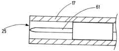
도 1은 기구(13)의 측면도에서, 내시경 및 본 발명의 전기수술 기구의 가스 공급 라인(12)을 갖는 본 발명의 장치(10)를 도시하고 - 상기 가스 공급 라인은 내시경의 작업 채널을 통해 - 환자의 인체의 체강(14)에서 연장된다. 대안적으로, 본 발명의 기구(13)는, 예를 들어 내시경(11) 외부로 안내될 수 있다. 내시경(11)은 예로서 길이방향 연장부(15)의 방향에 대해 만곡된 원위 단부(16)를 갖는 것으로 도 1에 도시된다. 내시경(11)의 작업 채널로부터 돌출된 기구(13)의 헤드(17)는 기구(13)의 원위 단부 섹션을 형성한다. 기구(13)는 도 1에 도시된 가스 공급 유닛(18)과 RF 발생기(19)에 연결된다.1 shows an
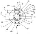
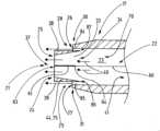
도 2a는 도 2b의 교차 라인(A-A)를 따른 길이방향 단면도에서 그 헤드(17)를 갖는 전기수술 기구(13)의 상세부를 도시한다. 도 2b는 기구 헤드(17)의 외측으로부터 기구 헤드(17)의 면 측(21)으로 정면에서 도 2a의 기구 헤드(17)를 도시한다. 기구(13)는 가스 공급 라인(18)에 연결되는 채널(22)을 가진다. 채널(22)은 면 측(21)의 중심 영역(24)에 제공된 제 1 개구(25) 및 중심 영역(24) 둘레의 면 측(21)의 주변 영역(28,29)에 배치되는 2개의 제 2 개구(26, 27)에 유체적으로 연결되는 기구 헤드(17) 내의 루멘(23) 체강과 연계된다. 도시된 예시적 실시예에서, 2개의 개구(26, 27)는 기구 헤드(17)의 대향 측면(30, 31) 상에 제공된다. 도 2a 및 도 2b에 도시된 예시적 실시예에서 제 1 개구(25) 및 제 2 개구(26)는 기구 헤드의 면 측(21)에 위치하고, 제 1 개구(25) 및 제 2 개구(26, 27)는 대안적으로 기구 헤드(17)의 측면(32)에 제공될 수 있다.FIG. 2a shows a detail of the
루멘(23)과 제 1 개구(25) 사이에는, 기구 헤드(17)의 중심 1차 스트림 채널 섹션(33)이 배치되고, 상기 섹션은 루멘(23)을 제 1 개구(25)에 유체적으로 연결한다.Between the
각각의 제 2 개구(26, 27)는 입구(34)의 대향 측면 상의 1차 스트림 채널 섹션(33)의 입구(34) 상에 측방향으로 배치된다.Each
제 2 개구(26, 27) 및 제 1 개구(25)는 2차 스트림(38,39)이 제 1 개구(25)로부터 흐르는 1차 스트림(37) 옆에 있는 2개의 대향 측면 상에 형성되는 방식으로 배치된다.The
도시된 바와 같이, 제 2 개구(26, 27)가 제 1 개구(25)로부터 근위로 후퇴하게 배치되어 루멘(23)을 통해 유동 방향(40)에 대향하면, 유동 방향(40)으로 볼 때 - 일 측에서 제 1 개구(25) 및 다른 측의 제 2 개구(26, 27) 사이에 거리(x)가 형성된다. 근위로 후퇴된 제 2 개구(26, 27)로 인해, 가스의 제 2 개구(26, 27)는 제 1 개구(25)에 대해서 각각의 동일 거리(x)에서 제 1 개구에 대해서 - 유동 방향(40)과 대향하여 - 배치된다. 예를 들어, 거리(x)는 최대 5 밀리미터일 수 있고, 바람직하게는 최대 2 밀리미터이다. 예시적인 실시예에서, 거리(x)는 예를 들어, 1.2 밀리미터일 수 있다.As shown, when the
유동 방향(40)은 가스가 근위 단부(41) 상에 기구 헤드(17) 내로 채워질 때 가스가 루멘(23)을 통해 유동하는 방향이며, 상기 가스는 루멘(23)을 통해 유동 방향(40)으로 유동하고 그리고 제 1 개구(25) 및 제 2 개구(26, 27)로 유동한다.The
가스가 제 1 개구(25) 외부로 이동하는 개구 영역(42)은 기구 헤드(17) 내의 채널(22)의 벽(44)의 단부 에지(43)에 의해 경계 지어진다 - 여기서, 1차 스트림의 벽(44)의 단부 에지 - 여기서는 1차 스트림 채널 섹션(33)의 벽(44)의 단부 에지(43)에 의해서 경계 지어진다. 제 1 개구(25)의 개구 영역(42)은 1차 스트림 채널 섹션(33)을 통과하는 1차 스트림의 유동 방향(40)에 수직인 방향으로 연장되는 것이 바람직하다. 제 2 개구(26)의 개구 영역(45a, 45b)은 기구 헤드(17)를 통해 채널(22)의 벽(44)에서 - 이는 개구(26, 27)를 형성한다 - 각각 컷아웃의 외측 에지(46a, 46b)에 의해 경계 지어진다. 도시된 바와 같이, 제 2 개구(26, 27)의 개구 영역(45a, 45b)은 각각 제 1 개구(25)에 대한 유동 방향(40)에 대해 경사지게 배향된다. 기구 헤드(17)의 주변에 배치된 제 2 개구(26,27)의 개구 영역(45a, 45b)은 기구(13)의 면 측(21) 상의 기구 헤드(17) 외측에서 공간 안으로 향한다.The
도 2b로부터 추측할 수 있는 바와 같이, 예시적인 실시예의 제 1 개구(25)는 1차 스트림(37)의 형성을 촉진하기 위해 평평한 둥근 형상을 가지며, 제 1 치수에서 1차 스트림(37)의 유동 방향에 수직으로 측정된 크기는 제 1 치수에 수직으로 연장되는 제 2 치수에서 측정된 1차 스트림(37)의 유동 방향에 수직인 크기보다 크다. 이를 위해, 제 1 개구(25)의 개구 폭(51)은 그에 수직하게 측정된 개구 높이(52)보다 크다. 바람직하게는, 제 1 개구(25)는 타원형이다. 대안적으로, 제 1 개구(25)는 예를 들어, 직사각형, 원형 또는 정사각형일 수 있다. 제 1 개구(25)는 팬형 가스 스트림을 생성하도록 슬릿 노즐의 형성을 위해 슬릿까지 평탄화될 수 있다. 예를 들어, 제 1 개구(25)의 개구 폭(51)은 0보다 크고 가스 공급 라인(12)을 나타낼 수 있는 튜브의 직경의 최대 2.5 배까지의 치수를 가질 수 있다. 예를 들어, 제 1 개구(25)의 개구 높이(52)는 0 밀리미터보다 크고 튜브의 직경의 최대 2.5 배까지의 치수를 가질 수 있다. 제 1 개구의 개구 폭(51)은 예를 들어 최소 3 밀리미터에서 최대 4 밀리미터 사이일 수 있다. 제 1 개구(25)의 개구 높이(52)는 예를 들어 최소 0.7 밀리미터에서 최대 2 밀리미터 사이일 수 있다.As can be inferred from FIG. 2B , the
평면 단면을 갖는 전극이 헤드(17)에 배치되면, 제 2 개구(26,27)의 배치는 바람직하게는 단면의 영역에 대하여 대칭이다. 제 2 개구(26, 27)는 바람직하게는 1차 스트림 채널(33)의 입구(34) 둘레에 대칭으로 배치된다. 제 2 개구(26, 27)는 바람직하게는 제 1 개구(25)의 반대 측면(53, 54) 상에 흐르는 2차 스트림(38, 39)이 형성되는 방식으로 도시된 바와 같이, 배치되고, 상기 측면(53, 54)은 긴 측면(53, 54)의 제 1 개구(25)의 개구 폭(51)을 따라 연장된다. 1차 스트림(37)의 주변부를 부분적으로 둘러싸고 제 1 개구(25)의 긴 측면(53, 54)을 지나서 제 1 개구(25)의 대향 긴 측면(53, 54)의 벽 영역을 흐르는 2차 스트림(38,39)을 제 2 개구(26, 27)가 발생시키는 방식으로, 예를 들어 신장, 원호, 낫 또는 곡선 슬릿의 형상을 갖는 제 2 개구(26,27)가 1차 스트림 채널 섹션(33)의 둘레 - 예를 들어 그 입구(34) - 또는 제 1 개구(25) 둘레에 배치되면, 습기 및/또는 유체를 제 1 개구(25)의 긴 측면(53,54) 상의 벽 영역으로부터 멀리 또는 송풍제거할 수 있다.If an electrode with a planar cross-section is disposed on the
도시된 바와 같이, 제 2 개구(26,27)의 개구 폭(55)은 제 1 개구(25)의 개구 폭(51)보다 작을 수 있다. 예를 들어, 제 2 개구(26,27)의 개구 폭(55)은 0보다 크고 가스 공급 라인(12)을 형성할 수 있는 튜브 직경의 최대 2.5배까지의 치수를 각각 가질 수 있다. 예를 들어, 제 2 개구(26,27)의 개구 높이(56)는 0보다 크고 튜브 직경의 최대 1.25배까지의 치수를 각각 가질 수 있다. 제 2 개구(26,27)의 개구 폭(55)은 예를 들어, 최소 1.5㎜에서 최대 3.5㎜ 사이일 수 있다. 그에 대해서 수직으로 측정된 개구(26, 27)의 개구 높이(56)는 예를 들어 최소 0.1㎜ 내지 최대 0.5㎜일 수 있다.As shown, the
제 2 개구(26, 27)의 개구 폭(55)의 치수 및/또는 제 2 개구(26, 27)의 개구 높이(56)의 치수는 동일한 것이 바람직하다. 제 2 개구(26,27)의 개구 영역의 내용물은 동일한 것이 바람직하다. 도시된 예시적 실시예에서 제 1 개구(25)의 개구 영역은 제 2 개구(26,27)의 조합된 개구 영역보다 작다. 대안적으로, 제 1 개구(25)의 개구 영역은 제 2 개구(26, 27)의 조합 개구 영역의 개구 영역보다 크거나 또는 제 1 개구 영역(25)의 개구 영역은 제 2 개구(26, 27)의 조합 개구 영역과 동일할 수 있다.It is preferable that the size of the
채널(22) 및 루멘(23)을 통해 연장되는, 전기 라인(60)이 1차 스트림 채널 섹션(33)에 바람직하게 장착되는 전극(61)에 접속된다. 전극(61)에게 RF 전력을 연속적으로 또는 펄스 방식으로 공급하고, 기구(13)의 전극(61)과 조직(62) 사이에 플라즈마, 예를 들어 아르곤 플라즈마를 발생시키기 위하여 다이 라인(60)은 RF 발생기(19)에 접속되어서 고주파 교류 전압을 발생시킨다. 도면에 도시된 실시예에서, 기구(13)는 단일 전극(61)을 포함한다. 대안적으로, 하나 초과의 전극(61)이 제 1 개구(25) 내에 또는 도시되지 않은 제 1 개구(25)의 전방에서 기구 헤드(17)의 내부에 배치될 수도 있다. 예를 들어, 적어도 2 개의 전극이 제 1 개구(25)에 인접한 하나의 채널 섹션(33)에 배치될 수 있고, 및/또는 적어도 2개의 제 1 개구들(25)이 조합된 1차 스트림(37)을 생성하기 위해 기구 헤드(17)에 배치될 수 있고, 이 경우 적어도 하나의 전극(61)은 제 1 개구(25)의 전방의 채널 섹션에 배치된다.An
전극(61)은 바람직하게는 1차 스트림 채널 섹션(33)의 중심에 그리고 적어도 부분적으로 배치된다. 전극(61)의 원위 단부(63)는 예를 들어 도시된 바와 같이 제 1 개구(25)와 동일 높이일 수 있거나 또는 제 1 개구(25)로부터 돌출하고 또는 1차 스트림 채널 섹션(33) 내부에 배치될 수 있다.The
전극(61)의 근위 단부(64)는, 예를 들어 도시된 바와 같이, 1차 스트림 채널 섹션(33)의 입구(34)의 하류에 있는 1차 스트림 채널 섹션(33)의 내부에 배치되어, 전극(61)의 근위 단부(64)가 유동 방향(40)으로 볼 때 1차 스트림 채널 섹션(33)에 있는 입구(34)의 하류에 있다. 대안적으로, 근위 단부(64)는 2 개의 개구들(26,27) 사이에 또는제 2 개구들(26,27)의 전방에 배치되어서, 유동 방향(40)으로 볼 때 제 2 개구들(26, 27)은 전극의 근위 단부(64)의 하류에 배치된다. 전극(61)의 근위 단부(64)는 루멘(23) 내로 연장될 수 있다.The
전극(61)은 상기 전극(61)이 제 1 개구(25)의 개구 폭(51)을 따라서 전극(61)의 측방향 에지(65)로부터 반대 측방향 에지(66)까지 측정된 폭을 가지며 연장되는 방식으로 배향되도록 1차 스트림 채널 섹션(33)에서 바람직하게는 도시된 바와 같이 배치된다. 바람직하게는, 도시된 바와 같이, 전극(61)은 전극(61)이 제 2 개구(26, 27)의 개구 폭(55)에 의해서 형성된 2차 스트림들(38, 39)의 측방향 범위를 따라서 그 폭을 가지고 연장되는 방식으로 배향되게 기구 헤드(17)에 배치된다.the electrode (61) has a width measured from a lateral edge (65) to an opposite lateral edge (66) of the electrode (61) along the aperture width (51) of the first aperture (25); It is preferably arranged as shown in the primary
바람직하게는, 전극(61)은 혈소판, 주걱, 바늘 또는 칼의 형상을 갖는다. 전극(61)은 테이퍼진 원위 단부를 가질 수 있다.Preferably, the
바람직하게는, 전극(61)은 기구 헤드에 고정되고, 전극(61)의 혈소판, 주걱 또는 칼의 형상을 갖는 섹션이 전극(61)의 섹션의 과도한 치수에 기초하여 채널(22)의 섹션, 예를 들어 1차 스트림 채널 섹션(33) 및/또는 루멘(23)의 내부 치수에 비교되고, 채널(22)의 내부 벽 표면, 예를 들어 1차 스트림 섹션(33) 및/또는 루멘(23)에 대하여 반대 측을 향하여 자체 지지된다. 도 8b 및 도 8c에는 도 8a의 교차 라인 C-C를 따른 기구 헤드(17)의 부분 단면도가 예시적 방식으로 도시되어 있다. 도 8b는 테이퍼진 원위 단부를 갖는 혈소판 형상 전극(61)을 도시한다. 도 8c는 전극(61)을 장착하기 위한 혈소판 형상 근위 섹션 및 바늘형 원위 섹션을 갖는 전극을 도시한다.Preferably, the
루멘(23)으로부터 측방향 제 2 개구(26,27)로의 유동 경로는 난류 가스 스트림을 방지하기 위해 전극없는 것이 바람직하다.The flow path from the
채널(22)은 가스 공급 유닛(18)에 의해 제공된 가스, 특히 아르곤을 채널(22)을 통해 채널(22)의 루멘(23) 내로 개구(25, 26, 27)로 안내하도록 배치되고, 상기 가스는 2차 스트림들(38, 39)을 통해서 1차 스트림(37)을 동반하고 및/또는 주변 방향으로 적어도 부분적으로 둘러싸기 위하여, 제 1 개구(25)로부터 1차 스트림(37)으로서 그리고 제 2 개구(26,27)로부터 기구 헤드(17)로부터 멀어지는 방향으로 1차 스트림(37) 주위로 적어도 부분적으로 주변으로 및/또는 그에 옆에 흐르는 주변 2차 스트림들(38, 39)로서 흐른다.The
1차 스트림 채널 섹션(33)의 스트림의 유동의 단면은 제 1 개구(25)를 향하는 방향으로 테이퍼진다. 1차 스트림 채널 섹션(33)의 유동 단면적 내용이 유동 방향(40)으로 감소한다면, - 1차 스트림 채널 섹션(33)에서 - 가스가 제 1 개구(25)로부터 배출되기 전에 제 1 개구(25)의 방향으로 1차 스트림 채널 섹션(33)를 통해 흐르는 가스가 가속된다.The cross section of the flow of the stream in the primary
본 발명에 따른 장치(10)는 다음과 같이 작동한다:The
플라즈마(69)를 점화시키기 위해(도 1), 사용자는 기구 헤드(17)를 처리될 조직(62)의 근방 내로 이동시키고 가스 공급 유닛(18)을 작동시켜서, 가스가 유동 방향(40)으로 채널(22)을 통해 입구(70)로부터 헤드(17) 내의 루멘(23) 안으로 및 기구 헤드(17)의 루멘(23) 안으로 유동할 것이다. 예를 들어, 가스 공급 유닛(18)은 분당 적어도 0.3 리터의 가스 내지 분당 최대 5 리터의 가스, 예를 들어 분당 1.5 리터의 가스의 가스 유동을 루멘(23)에 공급하도록 배치될 수 있다. 공급된 가스 스트림은 루멘(23)을 통해 유동 방향(40)으로 흐르고, 이어서 점화 전극(61)을지나 이동되는 중심 1차 스트림(37)과 가스의 하나 또는 여러 2차 스트림들(38, 39)로 기구 헤드(17)에서 분할되고, 상기 스트림은 기구 헤드(17)로부터 멀리 적어도 부분적으로 주변부로 1차 스트림(37) 옆에 대향 측면 상에 흐른다. 2차 스트림들(38, 39) 및 1차 스트림(37)은 제 1 개구(25) 및 제 2 개구(26, 27)가 기구 헤드(17) 내부에 배치된 루멘(23)에 공급되기 때문에 동일 가스로 이루어진다.To ignite the plasma 69 (FIG. 1), the user moves the
1차 스트림(37)이 테이퍼링된 1차 스트림 채널 섹션(33)으로 인해 가속되면, 1차 스트림(37)의 정적 압력은 감소한다. 노즐을 형성하는 수렴 벽을 갖는 1차 스트림 채널 섹션(33)에 의해, 1차 스트림(37)을 위한 가스를 2차 스트림들(38, 39)의 가스에 대해 가속시켜, - 제 1 개구(25)에서 - 1차 스트림 37)은 2 개의 반대 측면상의 2차 스트림들(38, 39)보다 높은 유속을 나타낸다. 따라서, 본 발명에 따른 기구(13)에 의해서, 단지 하나의 작동 매체 가스를 사용하여 기구 헤드(17)로부터 멀리 가스 스트림(37, 38, 39)의 2 단계 속도 프로파일을 달성할 수 있다. 속도 프로파일은 예를 들어 제 1 개구(25) 상의 제 1 개구(25)의 레벨에서 측정될 수 있다. 압력 구배로 인해, 2차 스트림들(38, 39)은 1차 스트림(37)를 향해 당겨질 수 있다.When the
2차 스트림들(38, 39)은 1차 스트림 채널 섹션(33)의 채널 벽(75) 외부로 그리고 제 1 개구(25)를 지나 외부로 흐른다. 제 1 개구(25)의 에지 상에 수집된 습기 또는 유체는 바람직하게는 제 1 개구(25) 둘레의 기구 헤드(17)의 영역에서 퍼지는 1차 스트림 채널 섹션(37) 및 2차 스트림(38, 39)에 의해서 픽업되거나 또는 송풍제거되고, 이 경우 에어로졸이 형성되고, 상기 에어로졸은 1차 스트림(37) 및 2차 스트림(38, 39)에 의해서 각각 운반될 것이다. 따라서, 제거된 습기 또는 유체는 더 이상 점화 거리를 손상시킬 수 없다.The
제 1 개구(25)가 조직(62)에 충분히 근접하게 배치되면, - RF 발생기(19)에 의한 전극(61)의 RF 공급부의 활성화에 의해 - 1차 스트림(37)에서 전극(61)과 조직(62) 사이에 점화 스파크가 형성될 수 있고, 상기 스파크는 플라즈마를 점화시킨다. 그렇게 할 때, 플라즈마는 주로 1차 스트림(37)의 가스의 이온화로 인해 1차 스트림(37)의 영역에서 형성된다. 1차 스트림(37) 상의 2차 스트림들(38, 39)의 영역도 또한 이온화될 수 있다. 외부로 더 멀리 흐르는 가스는 형성된 중심 플라즈마 스트림(37)에도 불구하고 비이온화된 상태로 잔류할 수 있어서, - 제 2 개구(26, 27)에 의해서 - 가스의 비이온화된 유동은 플라즈마 스트림(37) 주위에 적어도 부분적으로 또는 옆에 생성될 수 있다.When the
플라즈마 점화가 성공적으로 이루어지도록, 기구 헤드(17)의 면 측(21) 상의 제 1 개구(25)는 적어도 조직(62)을 향하여 점화 거리(78)까지 이동되어야 한다. 일반적으로, 점화 거리(78)는 수 밀리미터이다. 큰 점화 거리(78)가 바람직한데, 그 이유는 작은 점화 거리(78)에서는, 예를 들어 한편으로는 조직(62)과 접촉함으로써 기구 헤드(17)가 오염될 위험이 증가하고, 다른 한편, 플라즈마(69)와 동시에 처리된 영역은 상대적으로 작기 때문이다.For plasma ignition to be successful, the
본 발명에 따른 기구(13)에서, 1차 스트림(37)의 가로방향으로의 팽창 및 기구 헤드(17) 상의 제 1 개구(25)에서 나온 후에 비- 불활성, 습한 주위 매체와의 혼합이 1차 스트림(37)의 옆으로 유동하여 1차 스트림(37)을 바람직하게는 적어도 부분적으로 둘레로 둘러싸는 2차 스트림들(38, 39)에 의해 감소되고, 결과적으로 1차 스트림(37)의 작동 가스 농도는 2차 스트림들(38, 39)을 제공하지 않는 기구(13)와 비교하여 덜 급속하게 감소되는 것으로 추정된다. 제 2 개구(26, 27)로부터의 2차 스트림(38, 39)의 가스 입자가 1차 스트림(37) 상으로 이동할 수 있는 것으로 또한 추정된다. 상기 제 1 개구(25)에서 측정된 유속을 나타내고 상기 유속은 제 1 개구(25)의 레벨에서 측정된 상기 2차 스트림의 유속보다 큰, 1차 스트림(37)의 형성은 1차 스트림(37)의 안정화 및 그에 따른 점화 거리(77)의 확대를 유도하는 것으로 또한 추정된다. 어떤 경우에 있어서, 본 발명에 따른 기구(13)는 예를 들어 환자 인체의 체강(14)에 존재하는 습한 환경에서 큰 점화 거리(78)를 나타낸다.In the
도 2c는 바람직하게는 제 1 개구(25) 위로 돌출하는 안내부(80)를 갖는, 도 2a 및 도 2b에 따른 실시예를 도시하고, 상기 안내부는 기구 헤드(17)의 원위 단부(81)에 부착된 튜브 요소로서 구성된다.FIG. 2c shows the embodiment according to FIGS. 2a and 2b , with a
관형 안내부(80)에 대한 대안 또는 추가로서, 각각 하나의, 예를 들어 텅형상 안내부(80)가 기구 헤드 상의 제 2 개구(26, 27) 상에 배치될 수 있고, 상기 안내부(80)는 도시되지 않은 2차 스트림들(38, 39)의 유동 방향으로 개구(26, 27)를 넘어서 돌출한다. 프로브 헤드(17)로부터 멀어지는 방향으로 향하는 안내부의 단부는 제 1 개구의 전방에서 종료하여, 안내부는 제 1 개구를 넘어서 돌출하지 않는다. 텅형상 안내부(80)는 예를 들어 외향 방향으로 루멘(23)을 한정하는 제 2 개구(26, 27)를 넘어서는 벽(82)의 돌출부일 수 있다.As an alternative or addition to the tubular guides 80, each one, for example tongue-shaped
안내부(80)는 제 2 개구(26, 27)로부터 흐르는 2차 가스 스트림들(38, 39)이 각각 안내부(80)와 1차 스트림(37) 및 1차 스트림 채널 섹션(33) 사이로 흐르도록 설계 및 배치된다. 돌출 안내부(80)는 주변 매체에 대해 2차 스트림들(38, 39)을 한정하고 1차 스트림(37)으로부터 멀리 외부를 향하는 2차 스트림들(38, 39)의 가스의 팽창을 지연시키도록 배치되어서, 점화 거리(78)의 증가에 기여한다. 그렇게 하기 위해, 안내부(80)는 2차 스트림들(38, 39)이 유동하는 방사상 내측을 향한 안내 벽면(83)을 갖는다.The
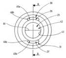
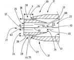
도 3a는 본 발명에 따른 기구(13)의 헤드(17)의 변형된 실시예의 도 3b의 교차 라인 B-B를 따른 길이방향 단면의 상세도이다. 도 3b는 도 3a의 기구의 정면도를 도시한다. 도 3a에서 알 수 있는 바와 같이, 루멘(23)과 제 1 개구(25) 사이에 배치되고 루멘(23)을 제 1 개구(25)에 연결시키는 1차 스트림 채널 섹션(33)의 입구(34)는 루멘(23)을 통과하는 가스의 유동 방향(40)의 역방향으로 제 2 개구(26,27)에 대해서 후퇴된다. 1차 스트림 채널 섹션(33)과 루멘(23)을 포함하는 벽 섹션을 갖는 기구 헤드(17)의 벽(82) 사이에는, 1차 스트림 채널 섹션(33) 옆에 있는 기구 헤드(17)의 주변 영역(28, 29) 내의 각각의 제 2 개구(26, 27) 전방에 있는 하나의 2차 스트림 채널 섹션(83, 84)이 형성된다. 서로 분리된 2차 스트림 채널 섹션(84, 85)은 각각 제 2 개구(26, 27)와 경계를 이룬다. 서로 분리된 2차 스트림 채널 섹션(84, 85)은 각각 제 2 개구(26, 27)와 경계를 이룬다. 예를 들어, 2차 스트림 채널 섹션(84, 85)은 신장, 원호 또는 낫(sickle)의 단면 형태를 가질 수 있다. 2차 스트림 채널 섹션(84, 85)은 바람직하게는 전극이 없다. 특히, 제 2 개구(26, 27) 내에 배치된 전극은 없다. 1차 스트림 채널 섹션(33)은 1차 스트림 채널 섹션(33)을 통해, 바람직하게는 1차 스트림 채널 섹션(33)의 입구(34) 전방에서 제 1 개구(25)까지 흐르는 가스를, 가스가 제 1 개구(25)를 빠져 나올 때까지, 2차 가스 스트림 채널 섹션(84, 85)를 통해서 흐르는 가스 및 프로브 헤드(17) 외부의 매체로부터 측방향으로 분리시킨다. 따라서, 1차 스트림 채널 섹션(33)을 제한하는 1차 스트림 채널 섹션(33)의 채널 벽은 바람직하게는 1차 스트림 채널 섹션(33)의 입구(34)와 제 1 개구(25)까지 사이에 개구들을 갖지 않는다. 대안으로 또는 추가로, 2차 스트림 채널 섹션(84, 85)을 한정하는 2차 스트림 채널 섹션(84, 85)의 채널 벽이 바람직하게는, 2차 스트림 채널 섹션(84, 85)을 통해 흐르는 가스를 측방향으로 분리시키기 위해, 2차 스트림 채널 섹션(84, 85)의 입구와 제 2 개구(26, 27)까지 사이에 개구들을 갖지 않는 구성을 2차 스트림 채널 섹션(84, 85) 모두에 적용시키는 것이 바람직하다.FIG. 3a is a detailed view of a longitudinal section along the intersection line B-B in FIG. 3b of a modified embodiment of the
따라서, 기구 헤드(17)는 기구 헤드(17) 내부의 루멘(23)을 통해 흐르는 가스를 1차 스트림 채널 섹션(33)을 통해 적어도 하나의 중심 1차 스트림(37)으로 분할하고 2차 스트림 채널 섹션(84, 85)에 있는 기구 헤드(17)의 1차 스트림 채널 섹션(33)의 반대편에 위치한 길이방향 측부를 통해서 2개의 주변 2차 스트림들(38, 39)로 분할하도록 구성된다. 2차 스트림 채널 섹션(84, 85)은 1차 스트림 채널 섹션(33) 옆에 제공되고, 도시된 바와 같이, 1차 스트림 채널 섹션(33)을 적어도 주변 섹션으로 둘러싼다.Thus, the
따라서, 기구 헤드(17)는 가스 스트림을 1차 스트림(37)과 2차 스트림들(38, 39)으로 분할하는 위치가 유동 방향(40)의 역방향으로 제 2 개구(26, 27)에 대해 후퇴되는 방식으로 구성된다.Accordingly, the
루멘(23)을 통한 스트림의 분할은 1차 스트림 채널 섹션(33)의 입구(34) 상의 기구 헤드(17) 내부에 있는 분할 에지(86) 상에서 달성되며, 상기 에지는 바람직하게는 유동 방향(40)의 역방향으로 칼 형상으로 테이퍼지도록 구성된다.Splitting of the stream through the
2차 스트림 채널 섹션(84, 85)은 제 2 개구(26, 27)로부터 배출되기 전에 2차 스트림들(38, 39)을 안내하도록 배치된다. 도 3a에 도시된 예시적인 실시예를 참조하면, 2차 스트림 채널 섹션(84, 85)의 유동 단면은 분할 위치로부터 개개의 제 2 개구(26, 27)까지 일정하게 유지된다. 예를 들어, 각각의 2차 스트림 채널 섹션(84, 85)은 0 밀리미터 초과 최대 30 밀리미터의 길이, 특히 0 밀리미터 초과 최대 10 밀리미터, 바람직하게는 0 밀리미터 초과 최대 5 밀리미터의 길이를 가질 수 있다.The secondary stream channel section (84, 85) is arranged to conduct the secondary streams (38, 39) before exiting from the second opening (26, 27). Referring to the exemplary embodiment shown in FIG. 3A , the flow cross sections of the secondary
분할 에지(86)는 유동 방향(40)과 역으로 도시되지 않은 채널(22) 내로 연장되는 분할 돌출부 상에 배치될 수 있고, 상기 돌출부는 기구 헤드(17) 내의 1차 스트림 채널 섹션(33) 및/또는 2차 스트림 채널 섹션(84,85)에 추가로 또는 대안으로 배치될 수 있다. 분할 돌출부는 기구 헤드(17) 내부의 1차 스트림(37)과 2차 스트림들(38, 39) 사이에 배치된다. 기술된 분할 에지(86)는 분할 돌출부 상에 제공될 수 있다.The splitting
도 3a, 도 3b에 따른 예시적 실시예에 있어서, 1차 스트림 채널 섹션(33)은 도 3a, 도 3b에 따른 예시적 실시예에서 1차 스트림 채널 섹션(33)의 유동 단면적이 루멘(23)으로부터 제 1 개구(25)를 향해 유동 방향(40)으로 감소하여, 1차 스트림 채널 섹션(33) 내의 가스가 가속되는 방식으로 구성된다.In the exemplary embodiment according to FIGS. 3a , 3b , the primary
도 3b로부터 명백한 바와 같이, 제 2 개구(26, 27) 및 2차 스트림 채널 섹션(84, 85)은 1차 스트림 채널 섹션(33)을 원호형으로 부분적으로 둘레로 둘러싸고 있다. 도 3a 및 도 3b에 따른 예시적인 실시예에서, 제 1 개구(25)는 원형이다. 제 2 개구(26, 27)를 한정하는 윤곽은 원호 프로파일을 갖는다. 제 1 개구(25)는 그로부터 벗어나 예를 들어 평평한 다각형 또는 평평한 둥근 형태, 예를 들어 타원 형태를 가질 수 있다. 제 2 개구(26, 27) 및 2차 스트림 채널 섹션(84, 85)은 1차 스트림 채널 섹션(33)을 부분적으로 둘레로 둘러싸기 위해 원호 프로파일로부터 벗어난 단면 형태를 가질 수 있다. 제 2 개구(26, 27) 및 2차 스트림 채널 섹션(84, 85)은 각각 단면 형태를 가질 수 있다. 제 2 개구(26, 27)의 개구 영역(45a, 45b)은 평면이고 2차 스트림 채널 영역(84, 85)의 단부 에지(46)에 의해 경계가 결정된다. 도 3a에 따른 예시적인 실시예에서, 제 2 개구(26, 27)의 개구 영역(45a, 45b)은 제 1 개구(25)의 개구 표면(42)과 같이 기구 헤드(17)로부터 멀어지는 방향과 본질적으로 동일 방향으로 향한다. 이외에는, 도 1, 도 2a 및 도 2b에 따른 실시예에 관한 설명은 도 3a, 도 3b에 따른 실시예와 유사하게 적용된다.As is apparent from FIG. 3B, the
바람직하게는, 기구 헤드(17)는 1차 스트림(37) 옆에 또는 1차 스트림(37) 주위에 하나 이상의 2차 스트림들(38, 39)을 생성하는 방식으로 구성되며, 제 1 개구(25)에서 측정된 2차 스트림 또는 2차 스트림들(38,39)은 제 1 개구(25)에서 측정된 1차 스트림(37)보다 높은 유속 또는 유속들을 나타낸다. 이를 달성하기 위해, 기구 헤드(17)는 예를 들어 2차 가스 스트림 또는 스트림들(38)을 위한 가스를 가속시키기 위해 및/또는 1차 스트림(37)에 대한 가스의 속도를 감소시키기 위해 배치될 수 있다. 1차 스트림에 대한 가스의 속도를 감소시키기 위해, 예를 들어 1차 스트림을 위한 가스의 유동 경로에서 기구(17)의 내부에 있는 하나 이상의 블레이드 및/또는 스크린과 같은 요소들을 배치할 수 있다. 기구 헤드(17)의 도움으로, 단지 하나의 작동 매체 가스를 사용함으로써 기구 헤드(17)로부터 멀어지는 가스 스트림(37, 38, 39)의 2 단계 속도 프로파일을 얻을 수 있다. 그 결과, 압력 구배가 1차 스트림(37)과 2차 스트림 또는 스트림들(38, 39) 사이에 존재할 수 있고, 그 결과 1차 스트림(37)은 2차 스트림(38) 또는 2차 스트림들(39)로 당겨질 수 있다.Preferably, the
도 4는 기구 헤드(17)를 갖는 본 발명에 따른 기구(13)의 예시적인 실시예의 상세도를 도시하며, 여기서 2차 스트림 채널 섹션(84, 85)의 유동 단면적은 도 3a에 따른 예시적인 실시예의 변형 예에서, 제 2 개구(26, 27)를 향한 유동 방향(40)으로 2차 스트림 채널 섹션(84, 85)의 입구(87)의 전방에서 감소한다. 그 결과로써, 루멘(23)으로부터 2차 스트림 채널 섹션(84, 85)을 통해서 제 2 개구(26, 27)로 흐르는 가스는 2차 스트림 채널 섹션(84, 85)에서 가속된다. 도시된 실시예에서, 1차 스트림 채널 섹션(33)의 유동 단면은 1차 스트림 채널 섹션(33)의 입구(34)로부터 제 1 개구(25)로 일정하게 유지된다. 1차 스트림 채널 섹션(33)의 유동 단면적뿐만 아니라 2차 스트림 채널 섹션(84, 85)의 유동 단면적은 가스가 제 1 개구(25) 및 제 2 개구(26, 27)를 각각 통과하기 전에 가스를 가속시키기 위해 개구(25, 26)를 향하는 방향으로 감소하는 변형예도 가능하다. 예를 들어, 기구 헤드(17)는 제 1 개구에서의 2차 스트림들(38, 39)의 유속이 제 1 개구에서의 1차 스트림(37)의 유속보다 높은 방식으로 2차 스트림 채널 섹션(84, 85)에서 가스의 가속을 위해 구성될 수 있다.FIG. 4 shows a detailed view of an exemplary embodiment of an
그 외에도, 도 4의 설명은 도 3a와 유사하게 적용된다. 도 4에 따른 실시예의 예시적인 도면이 정면에서 도 3b에 도시되어 있다.Besides that, the description of FIG. 4 applies similarly to FIG. 3A. An exemplary view of an embodiment according to FIG. 4 is shown in FIG. 3b from the front.
도 5는 변형된 실시예에 따른 기구 헤드(17)를 구비한 본 발명에 따른 기구(13)의 상세사항의 길이방향 단면도를 도시한다. 이 실시예에서, 2차 스트림 채널 섹션들(84, 85)은 1차 스트림 채널 섹션(33)의 1차 스트림에서 및/또는 2개의 개구(26, 27)로부터 2차 스트림(38)의 유동 방향을 표시하는 점선(88)으로 나타낸 바와 같이, 제 1 개구(25)의 하류에 있는 1차 스트림 채널 섹션(33) 외부에서 1차 스트림의 양 측에서 2차 스트림을 안내하는 방식으로 구성된다. 유동 방향은 2차 스트림 채널 섹션(84, 85)을 한정하는 2차 스트림 채널 섹션(84, 85)의 벽 면들의 배열로부터 발생한다. 2차 스트림 채널 섹션(84, 85)은 2차 스트림(38, 39)이 제 1 개구(25)의 개구 에지에서 정렬되는 방식으로 배치 또는 배향된다. 따라서, 다량의 2차 스트림들(38, 39)의 가스가 제 1 개구의 개구 에지를 점유하는 것이 달성될 수 있다.5 shows a longitudinal sectional view of a detail of an
도 5에 따른 실시예에서, 루멘(23)을 한정하는 기구 헤드(17)의 벽 섹션(89a, 89b)은 루멘(23)의 유동 단면적이 개구(25, 26, 27)를 향하는 방향으로 감소하는 방식으로 수렴한다. 개구(25, 26, 27)를 향하는 방향으로 루멘(23)의 유동 단면의 감소로 인해, 루멘(23)을 통해 흐르는 가스는 1차 스트림(37) 및 2차 스트림(38, 39)으로 분할되기 전에 이미 가속된다.In the embodiment according to FIG. 5 , the
그 외에도, 실시예의 설명은 도 3a, 도 3b와 유사하게 적용된다.Besides that, the description of the embodiment applies similarly to FIGS. 3A and 3B.
도 6은 도 5에 따른 실시예에 대응하는 기구(13)의 세부 사항을 도시하며, 상기 기구는 소수성 벽 표면을 갖는다. 도 1 내지 도 4의 실시예의 벽 면은 대응하는 소수성 벽면을 가질 수 있다:6 shows a detail of a
제 1 개구(25) 및/또는 제 2 개구(26, 27) 상의 기구 헤드(17)가 소수성이면, 이는 2차 스트림(38, 39) 및/또는 1차 스트림(37)에 의해서 제 1 개구(25)로부터 및/또는 제 2 개구(26,27)로부터 물 수용 유체를 송풍제거하거나 운반하는데 유리하다. 제 1 개구(25)를 내측으로 한정하는 벽면(90) 및/또는 제 2 개구(26, 27)를 내측으로 한정하는 벽면(91)이 소수성이면, 습기 또는 유체가 제 1 개구(25) 및 제 2 개구(26, 27)에 각각 모아지고 그리고 그들을 막히게 하는 위험성이 최소화된다.If the
바람직하게는, 1차 스트림 채널 섹션(33)과 경계를 이루고 및/또는 2차 스트림 채널 섹션(84, 85)과 내측으로 경계를 이루는 벽면(92, 93)은 습기가 1차 스트림 채널 섹션(33) 및 2차 스트림 채널 섹션(84, 85)에 모아지고 그리고 그들을 막히게 하는 위험성을 최소화하기 위해 소수성이다.Preferably, the
벽면(90 내지 93)은 예를 들면 소수성 코팅에 의해 소수성으로 만들어질 수 있다. 소수성 벽 표면(90 내지 93)은 PTFE로 제조될 수 있거나 PTFE- 코팅될 수 있다. 프로브 헤드(17)는 소수성 표면을 갖는 세라믹으로 제조되는 것이 바람직하다.The wall surfaces 90 to 93 can be made hydrophobic, for example by a hydrophobic coating. Hydrophobic wall surfaces 90-93 may be made of PTFE or may be PTFE-coated. The
도 7a는 예를 들어 세라믹으로 제조된 본 발명에 따른 기구 헤드(17)의 프로파일을 도시하며, 상기 기구 헤드는 가스 공급을 위해 기구 헤드(17)를 가스 공급 유닛(18)에 연결하는 가스 공급 라인(12)과 별개인 부분이다. 도 7b는 도 7a에 따른 기구 헤드(17)를 도시하고, 상기 기구 헤드는 기구(13)의 가스 공급 라인(12), 예를 들어 튜브 또는 가요성 파이프에 연결되며, 이 경우, 예에 따라서, 기구 헤드(17)는 공급 라인(12)의 원위 단부(94)에 고정된다.7a shows the profile of an
기구 헤드(17)의 대안으로서 가스 공급 라인(12)과 별개인 부분으로서, 기구 헤드(17)는 가스 공급 라인(12)의 원위 단부(94) 상의 섹션일 수 있다. 예를 들어, 본 발명에 따른 기구 헤드(17)는 라인(12)의 외장, 예를 들어 튜브 또는 가요성 파이프가 라인(12)의 길이방향의 크기의 방향에 대해서 가로방향으로 대향 측면 상의 그 단부에서 외장에 의해서 한정되는 루멘까지 방사상으로 노치되고, 라인(12)의 단부에서의 섹션(12)이 일 측면에서의 노치들 및 다른 측면에서 라인(12)의 단부 사이의 압축에 의해 평평해지도록 제조될 수 있다. 그렇게 할 때, 제 2 개구(26, 27)는 노치 상에 개방된다. 라인의 단부의 개구는 전극이 삽입될 수 있는 제 1 개구(25)를 형성한다. 예를 들어, 도 7a, 도 7b에 따른 기구 헤드(17)의 디자인은 상기 기술된 디자인과 동일할 수 있지만, 헤드(17)는 세라믹으로 이루어질 수 있다.As an alternative to the
도 9b는 도 9a의 절단 라인 C-C를 따른 본 발명에 따른 기구 헤드(17)를 통한 길이방향 단면도이다. 전극(61) 및 공급 라인(60)은 도시하지 않음. 최협소 지점에서의 1차 스트림 채널 섹션(33)의 유동 단면적(Ai) 및 최협소 지점에서의 2차 스트림 채널 섹션(84, 85)의 유동 단면적(AA)이 도시된다. 그 최협소 지점에서의 2차 스트림 채널 섹션(84, 85)의 유동 단면적(AA)의 합에 대한 그 최협소 지점에서의 1차 스트림 채널 섹션(33)의 유동 단면적(Ai)의 합의 비율은 바람직하게는 최대 3 : 1 내지 최소 1 : 3이다. 바람직하게는, 그 최협소 지점에서의 제 1 1차 스트림 채널 섹션(33)의 유동 단면적(Ai)의 합은 그 협소 지점에서의 2차 스트림 채널 섹션(84, 85)의 유동 단면적(AA)의 합보다 크다. 2차 스트림 채널 섹션(84, 85) 및/또는 1차 스트림 채널 섹션(33)은 채널 섹션을 유동하는 가스가 음속에 도달하는 방식으로 구성될 수 있다.FIG. 9b is a longitudinal section through the
도 10은 본 발명의 기구(13)의 기구 헤드(17)의 실시예를 길이방향 단면으로 도시한다. 전극(61) 및 그 공급 라인(60)은 도시하지 않음. 1차 스트림 채널 섹션(33)의 벽은 도시된 바와 같이, 1차 스트림 채널 섹션(33)의 벽의 기구 헤드(17)를 통해 중심에서 유동 방향(40)을 따른 길이방향 단면의 이벤트를 초래하는 두 개의 교차 영역이 낙하 형상을 갖는 방식으로 구성된다. 1차 스트림 채널 섹션(33)은 각각의 길이방향 교차 영역의 유동 방향에 대해서 가로방향으로 측정된 치수가 1차 스트림 채널 섹션(33)의 입구(34)에서 둥근 근위 단부로부터 제 1 개구(25)의 방향으로 초기에 증가하는 방식으로 구성되고 그리고 그 다음 길이방향 단면이 1차 스트림 채널 섹션(33)의 원위 단부를 향하는 방향으로 테이퍼지는 방식으로 하류로 테이퍼지는 방식으로 감소한다. 유동 방향(40)에 대해서 가로방향으로 측정된 길이방향 교차부의 치수가 길이방향 단면이 테이퍼지는 방식으로 1차 스트림 채널 섹션(33)의 원위 단부를 향하여 감소하는 방식으로, 본 발명에 따른 기구 헤드(17)의 1차 스트림 채널 섹션(33)이 구성되면, 습기는 특히 효과적인 방식으로 제 1 개구(25)로부터 송풍제거될 수 있다.10 shows an embodiment of the
도 11 및 도 12는 1차 스트림 채널 섹션(33) 둘레의 주변에 각각 배치된 수 개의 제 2 개구(26a 내지 26d 및 26a 내지 26c)를 갖는 정면으로부터의 기구 헤드(17)의 실시예를 도시한다. 본 발명에 따른 기구 헤드(17)의 제 2 개구의 배치는 전극의 폭 및 길이를 따라 연장되는 평면에 대해 대칭일 수 있다. 도 12는 제 2 개구(26a, 26b, 26c)의 배치가 전극면에 대해 대칭이 아닌 대안 예를 도시한다.11 and 12 show an embodiment of the
전기수술 치료를 위한 새로운 기구(13)가 설명되어 있다. 기구(13)는 기구 헤드(17)를 포함한다. 기구 헤드(17)는 루멘(23)이 가스로 충전될 때 가스가 기구 헤드(17)로부터 떠나는 개구로부터 기구 헤드(17)의 적어도 하나의 제 1 개구(25) 및 적어도 하나의 제 2 개구(26, 27)에 연결된다. 가스의 1차 스트림(37)은 조직(62)을 향하는 방향으로 기구 헤드(17)로부터 제 1 개구(25)를 통해서 떠나간다. 제 2 개구(26,27)는 2차 스트림(38, 39)이 제 2 개구(26, 27)로부터 떠나는 방식으로 제 1 개구(25)에 대해서 배치되고, 상기 2차 스트림은 1차 스트림(37) 옆에 및/또는 선택적으로 1차 스트림(37)을 적어도 부분적으로 주변으로 둘러싸며 기구 헤드(17)로부터 멀리 추가의 제 2 개구(26, 27)로부터 추가적인 2차 스트림들(38, 39)과 함께 유동한다. 2차 스트림(38, 39)은 바람직하게는 1차 스트림(37)을 감싼다. 기구 헤드(17)의 내부로부터 제 1 개구(25) 외부로 가스가 흐르는 경로에는, 제 1 개구(25)와 치료될 조직(62) 사이의 플라즈마를 점화시키기 위한 제 1 개구(61)가 배치된다. 1차 스트림(37)을 수반하도록 배치된 2차 스트림들(38, 39)으로 인하여, 기구(13)가 치료될 조직(62)으로부터 비교적 큰 거리(78)에 있더라도 플라즈마의 점화는 성공적이다. 1차 스트림(37)이 제 1 개구(25)로부터 코어 스트림으로서 본 발명에 따른 기구로 형성되고 2차 스트림들(38, 39)이 제 2 개구(26, 27) 외부로 감싸는 스트림으로 형성되면, 플라즈마의 점화는 조직(62)으로부터 기구(13)의 상대적으로 큰 거리에서 이미 성공적이다. 코어 스트림(37) 및 감싸는 스트림들(38, 39)은 동일한 루멘(23)에 의해 공급되어, 상기 스트림은 동일한 가스로 이루어진다.A novel instrument (13) for electrosurgical treatment is described. The
10 장치
11 내시경
12 가스 공급 라인
13 기구
14 몸체의 캐비티(루멘)
15 길이방향 크기의 방향
16 내시경의 원위 단부
17 헤드
18 가스 공급 유닛
19 FR 발생기
21 면 측
22 채널
23 루멘
24 중심 영역
25 제 1 개구
26, 26a, 26d 제 2 개구
27 제 2 개구
28 주변 영역
29 주변 영역
30 기구 헤드의 측부
31 기구 헤드의 측부
32 측방향 표면
33 1차 스트림 채널 섹션
34 입구
37 1차 스트림/플라즈마 유동
38 2차 스트림
39 2차 스트림
40 유동 방향
41 근위 단부
42 개구 영역
43 단부 에지
44 벽
45a, 45b 개구 영역
46a, 46b 에지
51 개구 폭
52 개구 높이
53 측부
54 측부
55 개구 폭
56 개구 높이
60 전기 라인
61 전극
62 조직
63 전극의 원위 단부
64 전극의 근위 단부
65 에지
66 에지
69 플라즈마
70 입구
75 채널 벽
78 거리/ 점화 거리
80 안내부
81 원위 단부
82 벽
82a, 82b 벽 섹션
83 안내 벽 표면
84 2차 스트림 채널 섹션
85 2차 스트림 채널 섹션
86 분할 에지
87 입구
88 라인
89a, 89b 벽 섹션
90 내지 93 벽 표면
94 가스 공급 라인의 원위 단부
x 거리
Ai 유동 단면적
AA 유동 단면적
A - A 교차 라인
B - B 교차 라인
C - C 교차 라인10 devices
11 Endoscopy
12 gas supply line
13 Organization
14 Cavity in body (lumens)
15 Direction of longitudinal magnitude
16 Distal end of endoscope
17 head
18 gas supply unit
19 FR generator
21 side
22 channels
23 lumens
24 central area
25 first opening
26, 26a, 26d second opening
27 second opening
28 surrounding area
29 Peripheral area
30 side of instrument head
31 side of instrument head
32 Lateral surfaces
33 Primary Stream Channel Section
34 entrance
37 Primary Stream/Plasma Flow
38 secondary stream
39 secondary stream
40 flow direction
41 proximal end
42 aperture area
43 end edge
44 wall
45a, 45b opening area
46a, 46b edge
51 opening width
52 opening height
53 side
54 side
55 opening width
56 opening height
60 electrical lines
61 electrode
62 organization
63 distal end of the electrode
64 proximal end of the electrode
65 edge
66 edge
69 Plasma
70 entrance
75 channel wall
78 distance/ ignition distance
80 information department
81 distal end
82 wall
82a, 82b wall section
83 guide wall surface
84 Secondary Stream Channel Section
85 Second Stream Channel Section
86 split edge
87 entrance
88 lines
89a, 89b wall section
90 to 93 wall surface
94 distal end of gas supply line
x distance
Ai flow cross-sectional area
AA Flow cross-sectional area
A - A cross line
B - B cross line
C - C cross line
Claims (14)
Translated fromKorean상기 헤드(17)는, 채널(22)의 가스 충전가능한 루멘(23)과, 상기 헤드(17)로부터 떨어져 가스의 1차 스트림(37)을 형성하도록 상기 루멘(23)에 연결된 제 1 개구(25) 및 상기 1차 스트림(37) 옆에 또는 상기 1차 스트림(37) 주위에 적어도 일부 주변으로 가스의 2차 스트림(38, 39)을 형성하기 위하여, 상기 루멘(23)에 연결된 적어도 하나의 제 2 개구(26, 27)를 갖고, 상기 헤드(17) 내에 전극(61)이 배치되고,
상기 1차 스트림(37)에 옆에 또는 상기 1차 스트림(37) 주위에 적어도 일부 주변으로 형성되는 상기 2차 스트림(38, 39)은 상기 1차 스트림(37)을 적어도 부분적으로 주변으로 둘러싸고,
상기 전극(61)은 상기 채널(22)의 채널 섹션(33)에 배치되고, 상기 채널의 채널 섹션은 상기 제 1 개구(25)로 이어져 상기 제 1 개구(25)에서 종료하고, 상기 전극(61)의 원위 단부(63)는 가스 유동 방향(40)으로 볼 때 상기 제 2 개구(26, 27)의 하류에 배치되는, 전기수술 기구(13).As an electrosurgical instrument (13) with a head (17),
The head 17 comprises a gas fillable lumen 23 of a channel 22 and a first opening connected to the lumen 23 to form a primary stream 37 of gas away from the head 17. 25) and at least one connected to the lumen (23) to form a secondary stream (38, 39) of gas next to or at least partially around the primary stream (37). has second openings 26 and 27, and an electrode 61 is disposed in the head 17,
The secondary streams 38, 39 formed beside the primary stream 37 or at least partially around the primary stream 37 surround the primary stream 37 at least partially. ,
The electrode 61 is disposed in the channel section 33 of the channel 22, the channel section of the channel leading to the first opening 25 and ending at the first opening 25, the electrode ( The electrosurgical instrument (13), wherein the distal end (63) of 61) is disposed downstream of the second opening (26, 27) as viewed in the gas flow direction (40).
상기 적어도 하나의 제 2 개구(26, 27)는 상기 제 1 개구(25)로부터 후퇴(set back) 배치되는, 전기수술 기구(13).According to claim 1,
wherein the at least one second aperture (26, 27) is disposed set back from the first aperture (25).
상기 채널(22)은 상기 제 1 개구(25)에 연결된 1차 스트림 채널 섹션(33)을 가지며, 상기 1차 스트림 채널 섹션(33)의 유동 단면은 상기 제 1 개구(25)를 향하는 방향으로 상기 제 1 개구(25) 앞에서 감소하는, 전기수술 기구(13).According to claim 1 or 2,
The channel 22 has a primary stream channel section 33 connected to the first opening 25, and the flow cross section of the primary stream channel section 33 is directed towards the first opening 25. An electrosurgical instrument (13), which decreases in front of the first opening (25).
상기 1차 스트림 채널 섹션(33)의 입구(34)는 상기 제 2 개구 또는 상기 제 2 개구들과 동일한 높이로 종결되거나, 또는 상기 1차 스트림 채널 섹션(33)의 입구(34)는 상기 제 2 개구 또는 제 2 개구들(26, 27)로부터 근위로 후퇴 배치되는, 전기수술 기구(13).According to claim 3,
The inlet 34 of the primary stream channel section 33 may terminate flush with the second opening or second openings, or the inlet 34 of the primary stream channel section 33 may terminate at the same height as the second opening or the second openings. An electrosurgical instrument (13), disposed proximally retracted from the two or second apertures (26, 27).
상기 제 1 개구들(25)의 개구 영역(42)은 상기 제 2 개구들(26, 27)의 개구 영역(45a, 45b)보다 큰, 전기수술 기구(13).According to claim 1 or 2,
The electrosurgical instrument (13), wherein the opening area (42) of the first openings (25) is larger than the opening areas (45a, 45b) of the second openings (26, 27).
상기 제 1 개구(25)의 개구 폭(51)은 상기 개구 폭(51)에 대해 직교방향으로 측정된 상기 제 1 개구(25)의 개구 높이(52)보다 큰, 전기수술 기구(13).According to claim 1 or 2,
wherein an aperture width (51) of the first aperture (25) is greater than an aperture height (52) of the first aperture (25) measured orthogonally to the aperture width (51).
상기 제 2 개구(26, 27)는 신장(kidney) 또는 원호 또는 낫 형상을 갖는, 전기수술 기구(13).According to claim 1 or 2,
The electrosurgical instrument (13), wherein the second opening (26, 27) has a kidney or arc or sickle shape.
상기 1차 스트림 채널 섹션(33) 옆에 또는 상기 1차 스트림 채널 섹션(33)을 둘러싸는, 상기 제 2 개구(26, 27)에 연결된 2차 스트림 채널 섹션(84, 85)이 배치되는, 전기수술 기구(13).According to claim 3,
next to the primary stream channel section (33) or surrounding the primary stream channel section (33) are disposed secondary stream channel sections (84, 85) connected to the second openings (26, 27); Electrosurgical instruments (13).
상기 2차 스트림 채널 섹션(84, 85)의 유동 단면은 상기 제 2 개구(26, 27)를 향하는 방향으로 상기 제 2 개구(26, 27) 앞에서 감소하는, 전기수술 기구(13).According to claim 8,
wherein the flow cross section of the secondary stream channel section (84, 85) decreases before the second opening (26, 27) in a direction towards the second opening (26, 27).
상기 1차 스트림 채널 섹션(33)의 입구(34)는 분할 에지(86)를 포함하는, 전기수술 기구(13).According to claim 3,
The electrosurgical instrument (13), wherein the inlet (34) of the primary stream channel section (33) comprises a dividing edge (86).
상기 전기수술 기구(13)는 단극성 기구인, 전기수술 기구(13).According to claim 1 or 2,
The electrosurgical instrument (13), wherein the electrosurgical instrument (13) is a unipolar instrument.
상기 전극(61)은 혈소판, 주걱, 바늘 또는 칼의 형상을 갖는, 전기수술 기구(13).According to claim 1 or 2,
Electrosurgical instrument (13), wherein the electrode (61) has the shape of a platelet, spatula, needle or knife.
Applications Claiming Priority (2)
| Application Number | Priority Date | Filing Date | Title |
|---|---|---|---|
| EP17174743.9AEP3412234B1 (en) | 2017-06-07 | 2017-06-07 | Instrument with a multi-flow instrument head for argon-plasma coagulation |
| EP17174743.9 | 2017-06-07 |
Publications (2)
| Publication Number | Publication Date |
|---|---|
| KR20180133802A KR20180133802A (en) | 2018-12-17 |
| KR102535433B1true KR102535433B1 (en) | 2023-05-24 |
Family
ID=59053945
Family Applications (1)
| Application Number | Title | Priority Date | Filing Date |
|---|---|---|---|
| KR1020180064223AActiveKR102535433B1 (en) | 2017-06-07 | 2018-06-04 | Instrument with a multistream instrument head for argon plasma coagulation |
Country Status (8)
| Country | Link |
|---|---|
| US (1) | US12156687B2 (en) |
| EP (1) | EP3412234B1 (en) |
| JP (1) | JP7079153B2 (en) |
| KR (1) | KR102535433B1 (en) |
| CN (1) | CN108992163B (en) |
| BR (1) | BR102018010654A2 (en) |
| PL (1) | PL3412234T3 (en) |
| RU (1) | RU2748309C2 (en) |
Families Citing this family (10)
| Publication number | Priority date | Publication date | Assignee | Title |
|---|---|---|---|---|
| EP3714926A1 (en)* | 2019-03-28 | 2020-09-30 | Erbe Elektromedizin GmbH | Instrument, instrument head, application system and method |
| WO2021022510A1 (en)* | 2019-08-07 | 2021-02-11 | Covidien Lp | Electrosurgical systems |
| AU2020330099B2 (en) | 2019-08-14 | 2024-02-01 | Biocompatibles Uk Limited | Flexible cryoprobe |
| EP4013324B1 (en)* | 2019-08-14 | 2025-09-24 | Biocompatibles UK Limited | Dual stage cryocooler |
| EP3943029B1 (en)* | 2020-07-23 | 2025-04-02 | Erbe Elektromedizin GmbH | Plasma probe with improved ignition behaviour |
| EP3984480A1 (en) | 2020-10-16 | 2022-04-20 | Erbe Elektromedizin GmbH | Multi-lumen probe |
| US20220022933A1 (en)* | 2021-07-14 | 2022-01-27 | Erbe Elektromedizin Gmbh | Plasma Probe with Improved Ignition Behavior |
| EP4458296A1 (en)* | 2023-05-04 | 2024-11-06 | Erbe Elektromedizin GmbH | Plasma instrument |
| GB2637024A (en)* | 2024-01-04 | 2025-07-09 | Era Medical Ltd | Treatment of living biological surfaces with plasma |
| CN118902592B (en)* | 2024-10-10 | 2024-12-13 | 浙江工业大学 | Tool bit auxiliary device of low-temperature plasma tool |
Citations (4)
| Publication number | Priority date | Publication date | Assignee | Title |
|---|---|---|---|---|
| US20020058938A1 (en) | 1996-09-20 | 2002-05-16 | Ioan Cosmescu | Multifunctional telescopic monopolar/bipolar surgical device and method therefore |
| US20030105458A1 (en) | 1999-10-05 | 2003-06-05 | Platt Robert C. | Multi-port side-fire coagulator |
| US20040044342A1 (en)* | 2002-09-03 | 2004-03-04 | Mackay Dale Victor | Electrosurgical apparatus |
| JP2008543355A (en) | 2005-05-09 | 2008-12-04 | エルベ エレクトロメディジン ゲーエムベーハー | Endoscopic surgery device for argon plasma coagulation |
Family Cites Families (21)
| Publication number | Priority date | Publication date | Assignee | Title |
|---|---|---|---|---|
| US4060088A (en)* | 1976-01-16 | 1977-11-29 | Valleylab, Inc. | Electrosurgical method and apparatus for establishing an electrical discharge in an inert gas flow |
| JPS6228084A (en) | 1985-07-30 | 1987-02-06 | Akira Kanekawa | Plasma jet torch |
| US6770071B2 (en)* | 1995-06-07 | 2004-08-03 | Arthrocare Corporation | Bladed electrosurgical probe |
| US7435247B2 (en) | 1998-08-11 | 2008-10-14 | Arthrocare Corporation | Systems and methods for electrosurgical tissue treatment |
| US6723091B2 (en)* | 2000-02-22 | 2004-04-20 | Gyrus Medical Limited | Tissue resurfacing |
| JP2002301088A (en)* | 2001-04-05 | 2002-10-15 | Olympus Optical Co Ltd | Endoscopic treatment device |
| US8623012B2 (en)* | 2001-08-15 | 2014-01-07 | Nuortho Surgical, Inc. | Electrosurgical plenum |
| US8057468B2 (en)* | 2002-12-17 | 2011-11-15 | Bovie Medical Corporation | Method to generate a plasma stream for performing electrosurgery |
| DE10351370B4 (en) | 2003-11-04 | 2011-08-11 | Erbe Elektromedizin GmbH, 72072 | Instrument for plasma coagulation |
| EP1850780B1 (en)* | 2005-02-11 | 2012-06-20 | MacKay, Dale Victor | An electrosurgical probe |
| WO2006096716A2 (en)* | 2005-03-07 | 2006-09-14 | Mounir Laroussi | Plasma generator |
| US7628788B2 (en)* | 2005-12-30 | 2009-12-08 | Biosense Webster, Inc. | Ablation catheter with improved tip cooling |
| DE102009044512B4 (en)* | 2009-09-11 | 2021-08-12 | Erbe Elektromedizin Gmbh | Anti-carbonization device |
| US8475451B2 (en)* | 2010-06-08 | 2013-07-02 | Kwangwoon University Industry-Academic Collaboration Foundation | Medical plasma generator and endoscope using the same |
| GB201117274D0 (en)* | 2011-10-06 | 2011-11-16 | Gyrus Medical Ltd | Electrosurgical apparatus and system |
| US9125662B2 (en) | 2012-06-28 | 2015-09-08 | Ethicon Endo-Surgery, Inc. | Multi-axis articulating and rotating surgical tools |
| US10299849B2 (en) | 2013-03-06 | 2019-05-28 | I.C. Medical, Inc. | Argon beam assisted electrosurgery pencil with smoke evacuation |
| ES2990184T3 (en) | 2013-05-23 | 2024-11-29 | Channel Medsystems Inc | Cryogenic treatment systems |
| PL3141203T3 (en) | 2015-09-10 | 2022-06-13 | Erbe Elektromedizin Gmbh | Ablation device for large-scale mucosa ablation |
| GB2548382B (en)* | 2016-03-16 | 2019-04-03 | Fourth State Medicine Ltd | Plasma generation |
| US10918433B2 (en)* | 2016-09-27 | 2021-02-16 | Apyx Medical Corporation | Devices, systems and methods for enhancing physiological effectiveness of medical cold plasma discharges |
- 2017
- 2017-06-07EPEP17174743.9Apatent/EP3412234B1/enactiveActive
- 2017-06-07PLPL17174743.9Tpatent/PL3412234T3/enunknown
- 2018
- 2018-05-24BRBR102018010654-6Apatent/BR102018010654A2/enunknown
- 2018-05-30RURU2018119933Apatent/RU2748309C2/enactive
- 2018-06-04KRKR1020180064223Apatent/KR102535433B1/enactiveActive
- 2018-06-06CNCN201810573784.5Apatent/CN108992163B/enactiveActive
- 2018-06-06USUS16/001,749patent/US12156687B2/enactiveActive
- 2018-06-07JPJP2018109166Apatent/JP7079153B2/enactiveActive
Patent Citations (5)
| Publication number | Priority date | Publication date | Assignee | Title |
|---|---|---|---|---|
| US20020058938A1 (en) | 1996-09-20 | 2002-05-16 | Ioan Cosmescu | Multifunctional telescopic monopolar/bipolar surgical device and method therefore |
| US20030105458A1 (en) | 1999-10-05 | 2003-06-05 | Platt Robert C. | Multi-port side-fire coagulator |
| US20040044342A1 (en)* | 2002-09-03 | 2004-03-04 | Mackay Dale Victor | Electrosurgical apparatus |
| JP2008543355A (en) | 2005-05-09 | 2008-12-04 | エルベ エレクトロメディジン ゲーエムベーハー | Endoscopic surgery device for argon plasma coagulation |
| US20090024122A1 (en)* | 2005-05-09 | 2009-01-22 | Klaus Fischer | Endoscopic-surgery apparatus for argon-plasma coagulation (apc) |
Also Published As
| Publication number | Publication date |
|---|---|
| RU2018119933A (en) | 2019-12-09 |
| JP2018202176A (en) | 2018-12-27 |
| EP3412234B1 (en) | 2022-11-16 |
| BR102018010654A2 (en) | 2019-01-15 |
| EP3412234A1 (en) | 2018-12-12 |
| JP7079153B2 (en) | 2022-06-01 |
| CN108992163B (en) | 2021-12-03 |
| US12156687B2 (en) | 2024-12-03 |
| CN108992163A (en) | 2018-12-14 |
| RU2018119933A3 (en) | 2021-04-14 |
| KR20180133802A (en) | 2018-12-17 |
| US20180353233A1 (en) | 2018-12-13 |
| RU2748309C2 (en) | 2021-05-21 |
| PL3412234T3 (en) | 2023-03-06 |
Similar Documents
| Publication | Publication Date | Title |
|---|---|---|
| KR102535433B1 (en) | Instrument with a multistream instrument head for argon plasma coagulation | |
| EP2314242B1 (en) | Tissue coagulation device using inert gas | |
| US6210410B1 (en) | Coagulation device for coagulating biological tissues | |
| US6666865B2 (en) | Swirling system for ionizable gas coagulator | |
| US9622768B2 (en) | Water jet surgical instrument | |
| JP5645916B2 (en) | Water jet surgical instruments | |
| US6579289B2 (en) | Probe electrode | |
| US10624689B2 (en) | Ablation device for large-area mucosal ablation | |
| EP0957793B2 (en) | Argon plasma flex-endoscopy coagulator | |
| JP2008543355A (en) | Endoscopic surgery device for argon plasma coagulation | |
| US9277953B2 (en) | Electrosurgical apparatus and system | |
| JP2005528737A (en) | Atmospheric plasma surface treatment method and apparatus for executing the same | |
| IL296585B1 (en) | Plasma system with directional features | |
| EP1090599B1 (en) | Swirling system for ionizable gas coagulator | |
| GB2573981A (en) | Electrosurgical probe and apparatus |
Legal Events
| Date | Code | Title | Description |
|---|---|---|---|
| PA0109 | Patent application | St.27 status event code:A-0-1-A10-A12-nap-PA0109 | |
| PG1501 | Laying open of application | St.27 status event code:A-1-1-Q10-Q12-nap-PG1501 | |
| P11-X000 | Amendment of application requested | St.27 status event code:A-2-2-P10-P11-nap-X000 | |
| P13-X000 | Application amended | St.27 status event code:A-2-2-P10-P13-nap-X000 | |
| PA0201 | Request for examination | St.27 status event code:A-1-2-D10-D11-exm-PA0201 | |
| R18-X000 | Changes to party contact information recorded | St.27 status event code:A-3-3-R10-R18-oth-X000 | |
| PE0902 | Notice of grounds for rejection | St.27 status event code:A-1-2-D10-D21-exm-PE0902 | |
| E13-X000 | Pre-grant limitation requested | St.27 status event code:A-2-3-E10-E13-lim-X000 | |
| P11-X000 | Amendment of application requested | St.27 status event code:A-2-2-P10-P11-nap-X000 | |
| P13-X000 | Application amended | St.27 status event code:A-2-2-P10-P13-nap-X000 | |
| E701 | Decision to grant or registration of patent right | ||
| PE0701 | Decision of registration | St.27 status event code:A-1-2-D10-D22-exm-PE0701 | |
| PR0701 | Registration of establishment | St.27 status event code:A-2-4-F10-F11-exm-PR0701 | |
| PR1002 | Payment of registration fee | St.27 status event code:A-2-2-U10-U11-oth-PR1002 Fee payment year number:1 | |
| PG1601 | Publication of registration | St.27 status event code:A-4-4-Q10-Q13-nap-PG1601 |