KR102534250B1 - Touch screen controller, touch sensing device, and touch sensing method - Google Patents
Touch screen controller, touch sensing device, and touch sensing methodDownload PDFInfo
- Publication number
- KR102534250B1 KR102534250B1KR1020180034759AKR20180034759AKR102534250B1KR 102534250 B1KR102534250 B1KR 102534250B1KR 1020180034759 AKR1020180034759 AKR 1020180034759AKR 20180034759 AKR20180034759 AKR 20180034759AKR 102534250 B1KR102534250 B1KR 102534250B1
- Authority
- KR
- South Korea
- Prior art keywords
- touch
- sensing
- driving signal
- driving
- touch sensing
- Prior art date
- Legal status (The legal status is an assumption and is not a legal conclusion. Google has not performed a legal analysis and makes no representation as to the accuracy of the status listed.)
- Active
Links
Images


Classifications
- G—PHYSICS
- G06—COMPUTING OR CALCULATING; COUNTING
- G06F—ELECTRIC DIGITAL DATA PROCESSING
- G06F3/00—Input arrangements for transferring data to be processed into a form capable of being handled by the computer; Output arrangements for transferring data from processing unit to output unit, e.g. interface arrangements
- G06F3/01—Input arrangements or combined input and output arrangements for interaction between user and computer
- G06F3/03—Arrangements for converting the position or the displacement of a member into a coded form
- G06F3/041—Digitisers, e.g. for touch screens or touch pads, characterised by the transducing means
- G06F3/0416—Control or interface arrangements specially adapted for digitisers
- G06F3/04166—Details of scanning methods, e.g. sampling time, grouping of sub areas or time sharing with display driving
- G06F3/041661—Details of scanning methods, e.g. sampling time, grouping of sub areas or time sharing with display driving using detection at multiple resolutions, e.g. coarse and fine scanning; using detection within a limited area, e.g. object tracking window
- G—PHYSICS
- G06—COMPUTING OR CALCULATING; COUNTING
- G06F—ELECTRIC DIGITAL DATA PROCESSING
- G06F3/00—Input arrangements for transferring data to be processed into a form capable of being handled by the computer; Output arrangements for transferring data from processing unit to output unit, e.g. interface arrangements
- G06F3/01—Input arrangements or combined input and output arrangements for interaction between user and computer
- G06F3/03—Arrangements for converting the position or the displacement of a member into a coded form
- G06F3/041—Digitisers, e.g. for touch screens or touch pads, characterised by the transducing means
- G06F3/0416—Control or interface arrangements specially adapted for digitisers
- G06F3/0418—Control or interface arrangements specially adapted for digitisers for error correction or compensation, e.g. based on parallax, calibration or alignment
- G06F3/04184—Synchronisation with the driving of the display or the backlighting unit to avoid interferences generated internally
- G—PHYSICS
- G06—COMPUTING OR CALCULATING; COUNTING
- G06F—ELECTRIC DIGITAL DATA PROCESSING
- G06F3/00—Input arrangements for transferring data to be processed into a form capable of being handled by the computer; Output arrangements for transferring data from processing unit to output unit, e.g. interface arrangements
- G06F3/01—Input arrangements or combined input and output arrangements for interaction between user and computer
- G06F3/03—Arrangements for converting the position or the displacement of a member into a coded form
- G06F3/041—Digitisers, e.g. for touch screens or touch pads, characterised by the transducing means
- G06F3/0412—Digitisers structurally integrated in a display
- G—PHYSICS
- G06—COMPUTING OR CALCULATING; COUNTING
- G06F—ELECTRIC DIGITAL DATA PROCESSING
- G06F3/00—Input arrangements for transferring data to be processed into a form capable of being handled by the computer; Output arrangements for transferring data from processing unit to output unit, e.g. interface arrangements
- G06F3/01—Input arrangements or combined input and output arrangements for interaction between user and computer
- G06F3/03—Arrangements for converting the position or the displacement of a member into a coded form
- G06F3/041—Digitisers, e.g. for touch screens or touch pads, characterised by the transducing means
- G06F3/0416—Control or interface arrangements specially adapted for digitisers
- G06F3/04166—Details of scanning methods, e.g. sampling time, grouping of sub areas or time sharing with display driving
- G06F3/041662—Details of scanning methods, e.g. sampling time, grouping of sub areas or time sharing with display driving using alternate mutual and self-capacitive scanning
- G—PHYSICS
- G06—COMPUTING OR CALCULATING; COUNTING
- G06F—ELECTRIC DIGITAL DATA PROCESSING
- G06F3/00—Input arrangements for transferring data to be processed into a form capable of being handled by the computer; Output arrangements for transferring data from processing unit to output unit, e.g. interface arrangements
- G06F3/01—Input arrangements or combined input and output arrangements for interaction between user and computer
- G06F3/03—Arrangements for converting the position or the displacement of a member into a coded form
- G06F3/041—Digitisers, e.g. for touch screens or touch pads, characterised by the transducing means
- G06F3/044—Digitisers, e.g. for touch screens or touch pads, characterised by the transducing means by capacitive means
- G06F3/0443—Digitisers, e.g. for touch screens or touch pads, characterised by the transducing means by capacitive means using a single layer of sensing electrodes
- G—PHYSICS
- G06—COMPUTING OR CALCULATING; COUNTING
- G06F—ELECTRIC DIGITAL DATA PROCESSING
- G06F3/00—Input arrangements for transferring data to be processed into a form capable of being handled by the computer; Output arrangements for transferring data from processing unit to output unit, e.g. interface arrangements
- G06F3/01—Input arrangements or combined input and output arrangements for interaction between user and computer
- G06F3/03—Arrangements for converting the position or the displacement of a member into a coded form
- G06F3/041—Digitisers, e.g. for touch screens or touch pads, characterised by the transducing means
- G06F3/044—Digitisers, e.g. for touch screens or touch pads, characterised by the transducing means by capacitive means
- G06F3/0446—Digitisers, e.g. for touch screens or touch pads, characterised by the transducing means by capacitive means using a grid-like structure of electrodes in at least two directions, e.g. using row and column electrodes
- G—PHYSICS
- G09—EDUCATION; CRYPTOGRAPHY; DISPLAY; ADVERTISING; SEALS
- G09G—ARRANGEMENTS OR CIRCUITS FOR CONTROL OF INDICATING DEVICES USING STATIC MEANS TO PRESENT VARIABLE INFORMATION
- G09G3/00—Control arrangements or circuits, of interest only in connection with visual indicators other than cathode-ray tubes
- G09G3/20—Control arrangements or circuits, of interest only in connection with visual indicators other than cathode-ray tubes for presentation of an assembly of a number of characters, e.g. a page, by composing the assembly by combination of individual elements arranged in a matrix no fixed position being assigned to or needed to be assigned to the individual characters or partial characters
- G09G3/2085—Special arrangements for addressing the individual elements of the matrix, other than by driving respective rows and columns in combination
- G09G3/2088—Special arrangements for addressing the individual elements of the matrix, other than by driving respective rows and columns in combination with use of a plurality of processors, each processor controlling a number of individual elements of the matrix
- G—PHYSICS
- G09—EDUCATION; CRYPTOGRAPHY; DISPLAY; ADVERTISING; SEALS
- G09G—ARRANGEMENTS OR CIRCUITS FOR CONTROL OF INDICATING DEVICES USING STATIC MEANS TO PRESENT VARIABLE INFORMATION
- G09G2310/00—Command of the display device
- G09G2310/02—Addressing, scanning or driving the display screen or processing steps related thereto
- G09G2310/0264—Details of driving circuits
Landscapes
- Engineering & Computer Science (AREA)
- Theoretical Computer Science (AREA)
- General Engineering & Computer Science (AREA)
- Physics & Mathematics (AREA)
- General Physics & Mathematics (AREA)
- Human Computer Interaction (AREA)
- Computer Hardware Design (AREA)
- Control Of Indicators Other Than Cathode Ray Tubes (AREA)
- Position Input By Displaying (AREA)
Abstract
Translated fromKoreanDescription
Translated fromKorean본 개시의 기술적 사상은 터치 센싱 장치에 관한 것으로서, 더욱 상세하게는, 디스플레이 타이밍 신호에 동기하여 동작하는 터치 컨트롤러, 이를 포함하는 터치 센싱 장치 및 터치 센싱 방법에 관한 것이다.The technical idea of the present disclosure relates to a touch sensing device, and more particularly, to a touch controller that operates in synchronization with a display timing signal, a touch sensing device including the touch controller, and a touch sensing method.
터치 센싱 장치는 디스플레이 장치의 화면에 나타난 내용에 응답하여 사용자가 손이나 터치 펜과 같은 물체를 사용하여 사용자의 입력을 전달할 수 있도록 하는 입력 장치이다. 터치 센싱 장치가 터치를 감지하는 방식으로서, 저항막 방식, 광감지 방식 및 정전용량 방식 등이 알려져 있다. 특히, 정전용량 방식은 사용자의 손이나 터치 펜과 같은 물체와 터치 센싱 장치의 전도성 전극이 형성하는 정전용량에 기초하여 터치 입력을 전기적 신호로 변환할 수 있다. 터치 센싱 장치가 디스플레이 장치의 전면에 구비되므로, 디스플레이 수행 시 발생하는 디스플레이 노이즈에 기인한 터치 센싱 감도 저하를 방지하기 위하여, 터치 센싱 장치는 디스플레이 타이밍 신호에 동기하여 터치 센싱을 수행할 수 있다.A touch sensing device is an input device that enables a user to transmit a user's input using an object such as a hand or a touch pen in response to content displayed on a screen of a display device. As a method of sensing a touch by a touch sensing device, a resistive method, an optical sensing method, a capacitive method, and the like are known. In particular, the capacitive method may convert a touch input into an electrical signal based on capacitance formed between an object such as a user's hand or a touch pen and a conductive electrode of a touch sensing device. Since the touch sensing device is provided on the front of the display device, the touch sensing device may perform touch sensing in synchronization with a display timing signal in order to prevent a decrease in touch sensing sensitivity due to display noise generated during display.
본 개시의 기술적 사상이 해결하려는 과제는 디스플레이 타이밍 신호에 동기하여 터치 센싱을 수행하면서, 터치 수행 시 발생하는 디스플레이의 화질 열화를 방지하는 터치 컨트롤러, 터치 센싱 장치 및 터치 센싱 방법을 제공하는 데 있다.An object to be solved by the technical idea of the present disclosure is to provide a touch controller, a touch sensing device, and a touch sensing method that perform touch sensing in synchronization with a display timing signal and prevent deterioration of display quality that occurs when a touch is performed.
상기 기술적 과제를 해결하기 위한 본 개시의 일 실시예에 따른, 터치 컨트롤러는 디스플레이 타이밍 신호를 수신하고, 상기 디스플레이 타이밍 신호에 동기하여 터치 센싱 제어 신호를 생성하는 컨트롤러, 및 상기 터치 센싱 제어 신호를 기초로 터치 센싱 어레이를 구동하고 상기 터치 센싱 어레이로부터 출력되는 센싱 신호들을 기초로 터치 데이터를 생성하며, 제1 디스플레이 프레임 구간에 제1 구동 신호를 상기 터치 센싱 어레이의 채널들에 제공하고, 제2 디스플레이 프레임 구간에 상기 제1 구동 신호와 반대 극성의 제2 구동 신호를 상기 채널들에 제공하는 센싱 회로를 포함할 수 있다.According to an embodiment of the present disclosure for solving the above technical problem, a touch controller receives a display timing signal and generates a touch sensing control signal in synchronization with the display timing signal, and based on the touch sensing control signal driving a touch sensing array and generating touch data based on sensing signals output from the touch sensing array, providing a first driving signal to channels of the touch sensing array in a first display frame period, and providing a second display A sensing circuit for providing a second driving signal having an opposite polarity to the first driving signal to the channels in a frame period may be included.
상기 기술적 과제를 해결하기 위한 본 개시의 일 실시예에 따른, 타치 센싱 장치는, 디스플레이 패널 상에 적층되며, 터치 입력을 센싱하기 위한 전극들을 포함하는 터치 센싱 어레이 및 상기 디스플레이 패널을 구동하는 디스플레이 구동 회로로부터 제공되는 동기 신호에 기초하여 터치 센싱 어레이를 구동하며, 상기 디스플레이 패널의 프레임이 변경됨에 따라서, 상기 터치 센싱 어레이의 상기 전극들에 제공되는 구동 신호들의 극성을 변경하는 터치 컨트롤러를 포함할 수 있다.According to an embodiment of the present disclosure for solving the above technical problem, a touch sensing device is stacked on a display panel and includes a touch sensing array including electrodes for sensing a touch input and a display drive for driving the display panel. and a touch controller that drives a touch sensing array based on a synchronization signal provided from a circuit and changes polarities of driving signals provided to the electrodes of the touch sensing array as a frame of the display panel is changed. there is.
상기 기술적 과제를 해결하기 위한 본 개시의 일 실시예에 따른, 터치 센싱 어레이에 발생하는 터치 입력을 센싱하는 터치 센싱 방법은, 터치 컨트롤러가 디스플레이 구동 회로로부터 제공되는 타이밍 신호에 동기하여 제1 디스플레이 프레임 구간에 제1 구동 신호를 기초로 상기 터치 센싱 어레이를 구동 및 센싱하는 제1 터치 센싱 단계 및 상기 터치 컨트롤러가 상기 타이밍 신호에 동기하여 제2 디스플레이 프레임 구간에 상기 제1 구동 신호와 반대 극성의 제2 구동 신호를 기초로 상기 터치 센싱 어레이를 구동 및 센싱하는 제2 터치 센싱 단계를 포함하는 할 수 있다.In a touch sensing method for sensing a touch input generated in a touch sensing array according to an embodiment of the present disclosure for solving the above technical problem, a touch controller synchronizes with a timing signal provided from a display driving circuit to display a first display frame. A first touch sensing step of driving and sensing the touch sensing array based on a first driving signal in a period, and the touch controller having a polarity opposite to that of the first driving signal in a second display frame period in synchronization with the timing signal. A second touch sensing step of driving and sensing the touch sensing array based on two driving signals may be included.
상기 기술적 과제를 해결하기 위한 본 개시의 일 실시예에 따른, 디스플레이 패널 및 터치 센싱 어레이를 구비하는 터치 스크린을 구동하는 구동 집적 회로는, 디스플레이 타이밍 신호를 기초로 상기 디스플레이 패널을 구동하는 디스플레이 구동 회로 및 상기 디스플레이 구동 회로로부터 수신되는 상기 디스플레이 타이밍 신호에 동기하여 상기 터치 센싱 어레이를 구동하며, 디스플레이 프레임 구간이 변경됨에 따라서, 상기 터치 센싱 어레이에 제공되는 구동 신호들의 극성을 변경하는 터치 컨트롤러를 포함할 수 있다.According to an embodiment of the present disclosure for solving the above technical problem, a driving integrated circuit for driving a touch screen having a display panel and a touch sensing array is a display driving circuit for driving the display panel based on a display timing signal. and a touch controller driving the touch sensing array in synchronization with the display timing signal received from the display driving circuit and changing polarity of driving signals provided to the touch sensing array as a display frame section changes. can
본 개시의 실시예에 따른, 터치 컨트롤러, 터치 센싱 장치 및 터치 센싱 방법에 따르면, 디스플레이 타이밍 신호에 동기하여 터치 센싱 수행 시, 디스플레이 프레임의 변경에 따라서, 터치 센싱을 위한 구동 신호의 극성을 변경함으로써, 디스플레이의 화질 열화를 방지할 수 있다.According to the touch controller, the touch sensing device, and the touch sensing method according to an embodiment of the present disclosure, when touch sensing is performed in synchronization with a display timing signal, the polarity of a driving signal for touch sensing is changed according to a change in a display frame. , it is possible to prevent deterioration of the image quality of the display.
도 1은 본 개시의 실시예에 따른 터치 스크린 장치를 나타낸다.
도 2a 및 도 2b는 구동 신호의 구현예를 나타내는 도면이다.
도 3a 및 도 3b는 본 개시의 실시예에 따른 터치 센싱 방법을 나타내는 도면이다.
도 4은 본 개시의 실시예에 따른 터치 센싱 장치를 나타내는 블록도이다.
도 5a는 및 도 5b는 터치 센싱 어레이의 구현예들을 나타낸다.
도 6은 본 개시의 실시예에 따른 터치 컨트롤러의 터치 센싱 방법을 나타내는 타이밍도이다.
도 7a는 본 개시의 실시예에 따른 터치 컨트롤러의 터치 센싱 방법의 일 예를 나타내는 타이밍도이고, 도 7b는 도 7a의 터치 센싱 방법에 따른 터치 스크린의 상태를 나타낸다.
도 8a는 본 개시의 실시예에 따른 터치 컨트롤러의 터치 센싱 방법의 일 예를 나타내는 타이밍도이고, 도 8b는 도 8a의 터치 센싱 방법에 따른 터치 스크린의 상태를 나타낸다.
도 9는 본 개시의 실시예에 따른 터치 컨트롤러의 터치 센싱 방법의 일 예를 나타내는 타이밍도이다.
도 10은 도 4의 AFE의 일 구현예를 나타내는 블록도이다.
도 11은 도 10의 수신기일 구현 예를 나타내는 회로도이다.
도 12는 상호 정전 용량 센싱 방식을 설명하는 도면이다.
도 13a 및 도 13b는 본 개시의 실시예에 따른 상호 정전용량 센싱 방식을 나타낸다.
도 14는 자기 정전용량 센싱 방식을 설명하는 도면이다.
도 15a 및 도 15b는 본 개시의 실시예에 따른 자기 정전용량 센싱 방식을 나타낸다.
도 16a 및 도 16b는 본 개시의 실시예에 따른 상호 정전용량 센싱 방식에 인가되는 구동 신호들의 예를 나타낸다.
도 17a 및 도 17b는 본 개시의 실시예에 따른 멀티 구동 방식을 나타낸다.
도 18a 및 도 18b는 본 개시의 실시예에 따른, 닷 센서를 포함하는 터치 센싱 어레이에 대한 터치 센싱 방법을 나타낸다.
도 19는 본 개시의 실시예에 따른 터치 컨트롤러의 터치 센싱 방법을 나타내는 흐름도이다.
도 20은 도 19의 터치 센싱 방법의 일 구현예를 나타내는 흐름도이다.
도 21은 본 개시의 실시예에 따른 스마트폰을 나타내는 도면이다.1 shows a touch screen device according to an embodiment of the present disclosure.
2A and 2B are diagrams illustrating an implementation example of a driving signal.
3A and 3B are diagrams illustrating a touch sensing method according to an embodiment of the present disclosure.
4 is a block diagram illustrating a touch sensing device according to an exemplary embodiment of the present disclosure.
5A and 5B show implementations of a touch sensing array.
6 is a timing diagram illustrating a touch sensing method of a touch controller according to an exemplary embodiment of the present disclosure.
7A is a timing diagram illustrating an example of a touch sensing method of a touch controller according to an embodiment of the present disclosure, and FIG. 7B illustrates a state of a touch screen according to the touch sensing method of FIG. 7A.
8A is a timing diagram illustrating an example of a touch sensing method of a touch controller according to an embodiment of the present disclosure, and FIG. 8B illustrates a state of a touch screen according to the touch sensing method of FIG. 8A.
9 is a timing diagram illustrating an example of a touch sensing method of a touch controller according to an embodiment of the present disclosure.
10 is a block diagram illustrating an implementation example of the AFE of FIG. 4 .
FIG. 11 is a circuit diagram illustrating an implementation example of the receiver of FIG. 10 .
12 is a diagram for explaining a mutual capacitance sensing method.
13A and 13B show a mutual capacitance sensing method according to an embodiment of the present disclosure.
14 is a diagram illustrating a self-capacitance sensing method.
15A and 15B show a self-capacitance sensing method according to an embodiment of the present disclosure.
16A and 16B show examples of driving signals applied to a mutual capacitance sensing method according to an embodiment of the present disclosure.
17A and 17B show a multi-driving method according to an embodiment of the present disclosure.
18A and 18B illustrate a touch sensing method for a touch sensing array including a dot sensor according to an embodiment of the present disclosure.
19 is a flowchart illustrating a touch sensing method of a touch controller according to an exemplary embodiment of the present disclosure.
20 is a flowchart illustrating an implementation example of the touch sensing method of FIG. 19 .
21 is a diagram illustrating a smart phone according to an embodiment of the present disclosure.
이하, 본 개시의 실시예가 첨부된 도면과 연관되어 기재된다.Hereinafter, embodiments of the present disclosure will be described in conjunction with the accompanying drawings.
도 1은 본 개시의 실시예에 따른 터치 스크린 장치를 나타낸다.1 shows a touch screen device according to an embodiment of the present disclosure.
본 개시의 실시예에 따른 터치 스크린 장치(1000)는 스마트폰 (smart phone), 랩탑 컴퓨터(laptop computer), 이동 단말, 태블릿(tablet) PC(Personal Computer), EDA (Enterprise Digital Assistant), 디지털 스틸 카메라(digital still camera), 디지털 비디오 카메라(digital video camera), PMP(Portable Multimedia Player), 휴대용 게임 콘솔(handheld game console), 웨어러블 컴퓨터, 사물 인터넷(internet of things(IoT)) 장치, 만물 인터넷 (internet of everything(IoE)) 장치, 드론(drone), 및 e-북(e-book) 등에 탑재될 수 있다. 그러나, 이에 한정되는 것은 아니며, 터치 센싱 장치(1000)는 터치 입력을 인식하고, 터치 입력에 따른 동작을 수행하는 다양한 전자 기기에 탑재될 수 있다.The
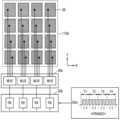
도 1을 참조하면, 터치 스크린 장치(1000)는 터치 스크린(100), 터치 컨트롤러(200) 및 디스플레이 구동 집적 회로(300)(이하, DDI라고 함)를 포함할 수 있다. 터치 컨트롤러(200) 및 DDI(300)는 터치 스크린 장치(1000)를 구동하는 구동 집적 회로(DIC)를 구성할 수 있다. 터치 컨트롤러(200) 및 DDI(300)는 동일한 반도체 칩 또는 서로 다른 반도체 칩에 형성 될 수 있다. Referring to FIG. 1 , a
터치 스크린(100)은 영상을 표시할 수 있으며, 영상에 표시된 내용에 따른 사용자의 터치 입력을 수신할 수 있다. 터치 스크린(100)은 전자 기기의 입/출력 장치로서 동작할 수 있다. 터치 입력은 터치 스크린(100) 상에 도전 물체(예를 들어, 사용자의 손가락, 손바닥, 터치 펜, 스타일러스 펜 등)가 직접 접촉하는 것뿐만이 아니라 상기 도전 물체가 터치 스크린(100)에 근접하는 것을 포함한다. 이하에서는, 사용자가 터치 스크린(100)에 터치 입력을 인가할 수 있는 도전 물체를 "오브젝트(object)"라고 정의하기로 한다.The
터치 스크린(100)은 디스플레이 패널(120) 및 터치 센싱 어레이(110)를 포함할 수 있다. 터치 센싱 어레이(110)는 디스플레이 패널(120) 상에 적층될 수 있다.The
디스플레이 패널(120)은 DDI(300)로부터 제공되는 영상 신호들(Simg)을 기초로 영상을 표시할 수 있다. 디스플레이 패널(120)은 행열로 배열된 복수의 화소들을 포함할 수 있으며, 로우 단위로 화소들에 영상 신호들(Simg)이 인가될 수 있다. 첫번째 로우부터 최종 로우까지 영상 신호들(Simg)이 차례로 인가됨으로써, 한 프레임의 영상이 표시될 수 있다. 영상은 설정된 프레임 레이트에 따라서 갱신될 수 있다.The
디스플레이 패널(120)은 LCD(liquid crystal display), LED(light emitting diode) 디스플레이, OLED(organic LED) 디스플레이, AMOLED(active-matrix OLED) 디스플레이, ECD(Electrochromic Display), DMD(Digital Mirror Device), AMD(Actuated Mirror Device), GLV(Grating Light Valve), PDP(Plasma Display Panel), ELD(Electro Luminescent Display), VFD(Vacuum Fluorescent Display) 중 하나로 구현될 수 있고, 그 밖에 다른 종류의 평판 패널 또는 플렉서블 패널로 구현될 수 있다.The
터치 센싱 어레이(110)는 터치 입력에 응답하여, 터치 입력에 대응하는 센싱 신호(Ssen)를 생성할 수 있다. 터치 센싱 어레이(110)는 터치 컨트롤러(200)로부터 수신되는 구동 신호(Sdrv)들을 기초로 센싱 신호(Ssen)들을 생성할 수 있다. 예를 들어서, 구동 신호(Sdrv)는 전압 신호이고, 센싱 신호(Ssen)는 전류 신호일 수 있다.The
터치 센싱 어레이(110)는 복수의 센싱 전극(SE)을 포함할 수 있으며, 복수의 센싱 전극(SE)은 제1 방향(예컨대 X축 방향) 및 제1 방향과 교차하는 제2 방향(예컨대 Y축 방향)으로 배열될 수 있다. 예를 들어서, 제1 방향은 제2 방향에 대해 실질적으로 수직일 수 있다. 제1 방향으로 배열된 제1 센싱 전극(SE1)들은 제1 채널들(예컨대 로우 채널들)을 형성하고, 제2 방향으로 배열된 제2 센싱 전극(SE2)들은 제2 채널들(예컨대 칼럼 채널들)을 형성할 수 있다. 복수의 센싱 전극(SE)은 커패시티브 터치 센서들일 수 있으며, 커패시티브 터치 센서는 ITO(indium tin oxide), IZO(indium zinc oxide) 또는 IZTO(indium zinc tin oxide)와 같은 투명 전도성 물질로 구현될 수 있다.The
실시예에 있어서, 터치 센싱 어레이(110)는 디스플레이 패널(120)과 일체로서 구현될 수 있다. 예를 들어, 터치 센싱 어레이(110)는 디스플레이 패널(120) 내부에 구현될 수 있으며, 센싱 전극(SE)은 디스플레이 패널(120) 내에 구비되는 각종 전극들 중 적어도 하나로 구현될 수 있다. 일 예로서, 디스플레이 패널(120)은 공통 전극, 게이트 라인 전극 및 데이터 라인 전극 등 다양한 종류의 전극들을 포함할 수 있으며, 터치 센싱 어레이(110)는 다양한 종류의 전극들 중 적어도 하나를 센싱 전극(SE)으로서 포함할 수 있다. 예컨대, 공통 전극이 터치 센싱 어레이(120)의 센싱 전극(SE)으로서 이용될 수 있다.In an embodiment, the
DDI(300)는 호스트(HOST)(예컨대, 애플리케이션 프로세서)로부터 제공되는 영상 데이터(IDT)를 영상 신호들(Simg)로 변환하고 영상 신호들(Simg)을 디스플레이 패널(120)에 제공함으로써, 디스플레이 패널(120)에 영상을 표시할 수 있다.The
DDI(300)는 디스플레이 패널(120) 구동을 위한 디스플레이 타이밍 신호(Tsig)를 터치 컨트롤러(200)에 제공할 수 있다. 예를 들어서, 디스플레이 타이밍 신호(Tsig)는 수직 동기 신호 및/또는 수평 동기 신호를 포함할 수 있다. 수직 동기 신호는 디스플레이 프레임 구간, 즉 디스플레이 패널(120)에 표시되는 영상의 프레임 구간을 나타내고, 수평 동기 신호는 디스플레이 패널(120)의 화소들에 로우 단위로 영상 신호들(Simg)이 인가되는 수평 구동 구간을 나타낸다.The
터치 컨트롤러(200)는 터치 센싱을 수행함으로써, 터치 입력의 발생 여부 및 터치 입력이 인가된 위치를 감지할 수 있다. 터치 컨트롤러(200)는 구동 신호(Sdrv)를 터치 센싱 어레이(110)에 제공하고, 구동 신호(Sdrv)에 기초하여 생성되는 센싱 신호(Ssen)들을 터치 센싱 어레이(110)로부터 수신할 수 있다. 터치 컨트롤러(200)는 센싱 신호(Ssen)들을 기초로 터치 입력의 발생 여부를 감지하고, 터치 입력이 발생한 위치, 즉 터치 좌표(Txy)를 산출할 수 있다. 터치 컨트롤러(200)는 터치 좌표(Txy)를 호스트(HOST)에 제공할 수 있다.The
실시예에 있어서, 터치 스크린(100)은 터치 입력의 압력(force)을 센싱하기 위한, 압력 센싱 전극을 더 포함할 수 있으며, 터치 컨트롤러(200)는 터치 센싱 어레이(110) 및 압력 센싱 전극을 구동함으로써, 터치 압력 센싱을 수행할 수 있다. 터치 컨트롤러(200)는 터치 압력을 산출하고, 터치 압력을 호스트(HOST)에 제공할 수 있다.In an embodiment, the
한편, 본 개시의 실시예에 따른 터치 컨트롤러(200)는 DDI(300)로부터 제공되는 디스플레이 타이밍 신호(Tsig)에 동기하여 터치 센싱을 수행할 수 있다. 예컨대, 터치 컨트롤러(200)는 디스플레이 타이밍 신호(Tsig)에 동기하여, 디스플레이 노이즈가 발생하지 않거나, 디스플레이 노이즈 발생량이 적은 구간에 터치 센싱을 수행할 수 있다. 또한, 터치 컨트롤러(200)는 디스플레이 프레임이 변경됨에 따라서, 구동 신호(Sdrv)의 극성을 변경할 수 있다. 예컨대, 터치 컨트롤러(200)는 제1 디스플레이 프레임 구간에는 제1 극성(+)의 구동 신호(Sdrv)를 터치 센싱 어레이(110)에 제공하고, 제2 디스플레이 프레임 구간에는 제2 극성(-)의 구동 신호(Sdrv)를 터치 센싱 어레이(110)에 제공할 수 있다. 실시예에 있어서, 터치 컨트롤러(200)는 디스플레이 프레임이 N번(N은 양의 정수) 변경될 때마다 구동 신호(Sdrv)의 극성을 변경할 수 있다.Meanwhile, the
전술한 바와 같이, 터치 센싱 어레이(110)가 디스플레이 패널(120) 상에 적층되거나 또는 디스플레이 패널(120)과 일체로서 형성됨에 따라서, 디스플레이 패널(120)과 터치 센싱 어레이(110)의 센싱 전극(SE) 사이에 기생 커패시터가 형성될 수 있다. 이러한 기생 커패시터로 인하여, 디스플레이 패널(120)에 영상 신호들(Ssig)이 인가될 때 발생하는 디스플레이 노이즈가 터치 센싱 어레이(110)에 영향을 미치며, 터치 센싱 감도를 저하시킬 수 있다. 본 개시의 실시예에 따른 터치 컨트롤러(200)는 디스플레이 타이밍 신호(Tsig)에 동기하여, 디스플레이 노이즈가 발생하지 않는 구간 또는 디스플레이 노이즈의 발생이 적은 구간에 터치 센싱을 수행함으로써, 디스플레이 노이즈를 회피할 수 있다.As described above, as the
한편, 매 디스플레이 프레임마다 터치 센싱 어레이(110)에 동일한 구동 신호(Sdrv)가 인가될 경우, 디스플레이 패널(120)의 특정한 로우의 화소들이 동일한 구동 신호(Sdrv)의 영향을 받아 화질 열화, 예컨대 시인성 가로줄 무늬가 형성되는 플리커 노이즈가 발생할 수 있다. 그런, 본 개시의 실시예에 따른 터치 컨트롤러(200)가 디스플레이 프레임이 변함에 따라 구동 신호(Sdrv)의 극성을 변경함으로써, 디스플레이 패널(120)에 표시되는 영상의 화질 열화(예컨대 플리커 노이즈)가 방지될 수 있다. 이에 따라서, 본 개시의 실시예에 따른 터치 스크린 장치(1000)는 화질 열화 없이, 터치 센싱 감도를 향상시킬 수 있다.Meanwhile, when the same driving signal Sdrv is applied to the
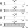
도 2a 및 도 2b는 구동 신호의 구현예를 나타내는 도면이다.2A and 2B are diagrams illustrating an implementation example of a driving signal.
도 2a를 참조하면, 제1 극성(+)의 구동 신호(Sdrv) 및 제2 극성(-)의 구동 신호(Sdrv)는 펄스 신호일 수 있다. 제1 극성(+)의 구동 신호(Sdrv)와 제2 극성(-)의 구동 신호(Sdrv)는 위상이 상이할 수 있으며, 위상 차이가 180도일 수 있다.Referring to FIG. 2A , the first polarity (+) driving signal Sdrv and the second polarity (−) driving signal Sdrv may be pulse signals. The driving signal Sdrv of the first polarity (+) and the driving signal Sdrv of the second polarity (−) may have different phases, and the phase difference may be 180 degrees.
도 2b를 참조하면, 제1 극성(+)의 구동 신호(Sdrv) 및 제2 극성(-)의 구동 신호(Sdrv)는 소정의 주기를 갖는 펄스 신호일 수 있다. 제1 극성(+)의 구동 신호(Sdrv) 및 제2 극성(-)의 구동 신호(Sdrv)의 주기는 동일할 수 있으며, 위상 차이가 180도일 수 있다.Referring to FIG. 2B , the first polarity (+) driving signal Sdrv and the second polarity (−) driving signal Sdrv may be pulse signals having a predetermined period. The period of the driving signal Sdrv of the first polarity (+) and the driving signal Sdrv of the second polarity (-) may be the same, and the phase difference may be 180 degrees.
한편, 도 2a 및 도 2b에서, 펄스는 구형파인 것으로 도시되었으나, 펄스는 다양하게 변경될 수 있다. 예컨대, 펄스는 삼각파, 정현파 등으로 구현될 수 있으며, 이 외에도 다양한 형태로 구현될 수 있다.Meanwhile, in FIGS. 2A and 2B , the pulse is illustrated as being a square wave, but the pulse may be variously changed. For example, the pulse may be implemented as a triangular wave, a sine wave, or the like, and may be implemented in various other forms.
도 3a 및 도 3b는 본 개시의 실시예에 따른 터치 센싱 방법을 나타내는 도면이다.3A and 3B are diagrams illustrating a touch sensing method according to an embodiment of the present disclosure.
도 3a를 참조하면, 제1 프레임 구간에(FRAME1), 즉 디스플레이 패널(120)에 제1 프레임의 영상이 표시될 때, 제1 극성(+)의 구동 신호(Sdrv)가 터치 센싱 어레이(110)에 인가되고, 제2 프레임 구간(FAMRE2)에, 제2 극성(-)의 구동 신호(Sdrv)가 터치 센싱 어레이(110)에 인가될 수 있다. 또한, 제3 프레임 구간(FRAME3)에 제1 극성(+)의 구동 신호(Sdrv)가 터치 센싱 어레이(110)에 인가되고, 제4 프레임 구간(FRAME4)에, 제2 극성(-)의 구동 신호(Sdrv)가 터치 센싱 어레이(110)에 인가될 수 있다. 매 프레임마다 구동 신호(Sdrv)의 극성이 변경될 수 있다.Referring to FIG. 3A , in the first frame period (FRAME1), that is, when the image of the first frame is displayed on the
도 3b를 참조하면, 제1 프레임 구간(FRAME1) 및 제2 프레임 구간(FRAME2)에 제1 극성(+)의 구동 신호(Sdrv)가 터치 센싱 어레이(110)에 인가되고, 제3 프레임 구간(FRAME3) 및 제4 프레임 구간(FRAME4)에 제2 극성(-)의 구동 신호(Sdrv)가 터치 센싱 어레이(110)에 인가될 수 있다. 두 프레임마다 구동 신호(Sdrv)의 극성이 변경될 수 있다.Referring to FIG. 3B , the driving signal Sdrv of the first polarity (+) is applied to the
도 3a 및 도 3b에서는 매 프레임마다 또는 두 프레임마다 구동 신호(Sdrv)의 극성이 변경되는 예가 도시되었으나, 본 개시의 기술적 사상은 이에 제한되는 것은 아니며, N 프레임(N은 양의 정수)마다 구동 신호(Sdrv)의 극성이 변경될 수 있다.3A and 3B illustrate an example in which the polarity of the driving signal Sdrv is changed every frame or every two frames, but the technical concept of the present disclosure is not limited thereto, and is driven every N frames (N is a positive integer). A polarity of the signal Sdrv may be changed.
이와 같이, 프레임이 변경될 때 터치 센싱 어레이(110)에 인가되는 구동 신호(Sdrv)의 극성이 변경되므로, 디스플레이 패널(120)(특히 화질 열화에 있어서 취약한 특정 영역)에 영향을 미치는 구동 신호(Sdrv)가 프레임이 변경됨에 따라서 극성이 변경될 수 있다. 그러므로 디스플레이 패널(120)의 특정 영역이 계속하여(예컨대 매 프레임마다) 동일한 구동 신호(Sdrv)의 영향을 받아 발생하는 화질 열화가 방지될 수 있다.In this way, since the polarity of the driving signal Sdrv applied to the
도 4은 본 개시의 실시예에 따른 터치 센싱 장치를 나타내는 블록도이다.4 is a block diagram illustrating a touch sensing device according to an exemplary embodiment of the present disclosure.
도 4를 참조하면, 터치 센싱 장치(1100)는 터치 센싱 어레이(110) 및 터치 컨트롤러(200)를 포함할 수 있다.Referring to FIG. 4 , the
도 1을 참조하여 설명한 바와 같이, 터치 센싱 어레이(110)는 복수의 센싱 전극들을 포함할 수 있다. 도 5a 및 도 5b를 참조하여 터치 센싱 어레이(110)를 예시적으로 설명하기로 한다.As described with reference to FIG. 1 , the
도 5a는 및 도 5b는 터치 센싱 어레이의 구현예들을 나타낸다.5A and 5B show implementations of a touch sensing array.
도 5a를 참조하면, 터치 센싱 어레이(110a)는 제1 방향(예컨대 X축 방향) 및 제2 방향(예컨대 Y축 방향)으로 배열되는 복수의 센싱 전극들, 예컨대, 로우 전극들(SE1) 및 컬럼 전극들(SE2)을 포함할 수 있다. 로우 전극들(SE1) 및 컬럼 전극들(SE2)의 형태는 다양하게 변경될 수 있다. 로우 전극들(SE1)은 전기적으로 연결되어 로우 채널들(R1 내지 Rn)을 형성하고, 칼럼 전극들(SE2)은 전기적으로 연결되어 칼럼 채널들(C1 내지 Cm)을 형성할 수 있다. 로우 채널들(R1 내지 Rn) 및 칼럼 채널들(C1 내지 Cm)은 배선(WE)(또는 트레이스라고 함)을 통해서 터치 컨트롤러(200)와 전기적으로 연결될 수 있다. 일 실시예에서, 로우 채널들(R1 내지 Rn)과 칼럼 채널들(C1 내지 Cm)은 서로 다른 레이어에 형성될 수 있다. 일 실시예에서, 로우 채널들(R1 내지 Rn)과 칼럼 채널들(C1 내지 Cm)은 동일한 레이어에 형성될 수 있다.Referring to FIG. 5A , the
도 5b를 참조하면, 터치 센싱 어레이(110b)는 동일한 레이어에 행열로 배열된 센싱 전극들(SE)을 포함하며, 센싱 전극들(SE) 각각은 배선(WE)를 통해 터치 컨트롤러(200)에 전기적으로 연결될 수 있다. 도 3b에 도시된 바와 같이 센싱 전극들(SE) 각각에 배선(WE)이 연결되는 구조에서, 센싱 전극들(SE)은 닷(dot) 센서로 지칭될 수 있다.Referring to FIG. 5B , the
도 5a 및 도 5b를 참조하여, 터치 센싱 어레이의 구현예를 설명하였다. 그러나, 이에 제한되는 것은 아니며, 터치 센싱 어레이의 구조 및 센싱 전극들의 형태는 다양하게 변경될 수 있다.An implementation example of the touch sensing array has been described with reference to FIGS. 5A and 5B . However, it is not limited thereto, and the structure of the touch sensing array and the shape of the sensing electrodes may be variously changed.
계속하여 도 4를 참조하면, 터치 컨트롤러(200)는 컨트롤러(210), 센싱 회로(220), 프로세서(230) 및 메모리(240)를 포함할 수 있으며, 센싱 회로(220)는 아날로그 프론트 엔드(221, 이하 AFE라고 함) 및 아날로그-디지털 변환기(222, 이하 ADC라고 함)를 포함할 수 있다. 터치 컨트롤러(200)는 다른 구성들을 더 포함할 수도 있다.Continuing to refer to FIG. 4 , the
컨트롤러(210)는 터치 컨트롤러(200)의 전반적인 동작을 제어할 수 있으며, 센싱 회로(220)의 터치 센싱 타이밍을 제어할 수 있다. 컨트롤러(210)는 DDI(300)로부터 디스플레이 타이밍 신호(Tsig)를 수신하고, 디스플레이 타이밍 신호(Tsig)를 기초로, 터치 센싱 타이밍을 제어할 수 있다. 또한, 컨트롤러(210)는 디스플레이 타이밍 신호(Tsig)를 기초로, 디스플레이 프레임이 변경됨에 따라 구동 신호(Sdrv)의 극성이 변경되도록 제어할 수 있다. 예를 들어서, 컨트롤러(210)는 디스플레이 타이밍 신호(Tsig)에 동기되는 터치 센싱 제어 신호를 생성하고, 터치 센싱 제어 신호를 AFE(221)에 제공할 수 있다. 터치 센싱 제어 신호는 타이밍 제어 신호 및 구동 신호(Sdrv)의 극성을 변경하기 위한 코드 신호를 포함할 수 있다. 일 실시예에 있어서, 구동 신호(Sdrv)를 생성하기 위한 다양한 코드 신호들이 메모리(240)에 저장되고, 컨트롤러(210)는 메모리(240)에 저장된 코드 신호들을 디스플레이 타이밍 신호(Tsig)에 동기하여 AFE(221)에 제공할 수 있다.The
AFE(221)는 터치 센싱 제어 신호에 기초하여 터치 센싱을 수행할 수 있다. AFE(221)는 디스플레이의 한 프레임 구간 내에 한번 또는 복수 번의 터치 센싱을 수행할 수 있으며, 프레임이 변경됨에 따라서, 구동 신호(Sdrv)의 극성을 변경할 수 있다. 예를 들어서, AFE(221)는 컨트롤러(210)로부터 제공되는 코드 신호를 기초로, 구동 신호(Sdrv)의 극성을 변경할 수 있다.The AFE 221 may perform touch sensing based on the touch sensing control signal. The AFE 221 may perform touch sensing once or multiple times within one frame period of the display, and may change the polarity of the driving signal Sdrv as the frame changes. For example, the AFE 221 may change the polarity of the driving signal Sdrv based on a code signal provided from the
AFE(221)는 구동 신호(Sdrv)를 터치 센싱 어레이(110)의 채널들에 제공하고, 동일한 채널들 또는 상이한 채널들로부터 센싱 신호(Ssen)들을 수신할 수 있다. AFE(221)는 증폭기(예컨대 전류 증폭기)를 포함할 수 있으며, 센싱 신호들(Ssen)을 증폭 및 변환하여, 아날로그 터치 값들을 생성할 수 있다.The AFE 221 may provide the driving signal Sdrv to channels of the
ADC(222)는 AFE(221)로부터 수신되는 아날로그 터치 값들을 디지털 터치 값으로 변환할 수 있다. ADC(222)는 디지털 터치 값들을 포함하는 터치 데이터(Tdt)를 프로세서(230)에 제공할 수 있다.The
프로세서(230)는 터치 데이터(Tdt)를 기초로 터치 좌표(Txy)를 산출할 수 있다. 실시예에 있어서, 프로세서(230)는 ADC(222)로부터 출력되는 터치 데이터(Tdt)를 메모리(240)에 저장하고, 이를 이용할 수 있다. 예를 들어서, 프로세서(230)는, ADC(222)로부터 출력되는 복수의 터치 데이터(Tdt)를 기초로 터치 좌표(Txy)를 산출할 수 있다.The
도 6은 본 개시의 실시예에 따른 터치 컨트롤러의 터치 센싱 방법을 나타내는 타이밍도이다.6 is a timing diagram illustrating a touch sensing method of a touch controller according to an exemplary embodiment of the present disclosure.
도 1 및 도 6을 참조하면, 터치 컨트롤러(200)는 DDI(300)로부터 제공되는 타이밍 신호(Tsig)에 동기하여, 터치 센싱을 수행할 수 있으며, 타이밍 신호(Tsig)는 예컨대, 수직 동기 신호(Vsync) 및 수평 동기 신호(Hsync)를 포함할 수 있다. 수직 동기 신호(Vsync)는 디스플레이 프레임 구간을 나타낼 수 있다.1 and 6 , the
터치 컨트롤러(200)는 수직 동기 신호(Vsync)에 동기하여, 매 프레임 구간마다 터치 센싱을 수행할 수 있다. 도 6에서는 매 프레임 구간마다 한 번의 터치 센싱이 수행되는 것으로 도시되었으나, 이에 제한되는 것은 아니며, 매 프레임 구간마다 복수 번의 터치 센싱이 수행될 수 있다. 한 번의 터치 센싱이 수행될 때, 터치 센싱 어레이(110) 전체가 센싱될 수 있으며, 센싱 결과를 기초로, 터치 컨트롤러(200)가 터치 좌표(Txy)를 산출할 수 있다.The
한편, DDI(300)는 수평 동기 신호(Hsync)에 동기하여, 다시 말해서, 수평 동기 신호(Hsync)의 라이징 엣지 또는 폴링 엣지에 응답하여, 영상 신호들(Simg)을 디스플레이 패널(120)에 출력할 수 있다. 영상 신호들(Simg)이 디스플레이 패널(120)에 출력될 때 디스플레이 노이즈가 발생할 수 있다. 터치 컨트롤러(200)는 수평 동기 신호(Hsync)에 동기하여 영상 신호들(Simg)이 디스플레이 패널(120)에 출력되지 않는 구간을 설정하고, 설정된 구간에 터치 센싱 어레이(110)에 구동 신호(Sdrv)를 제공하고, 터치 센싱 어레이(110)로부터 복수의 센싱 신호(Ssen)를 수신할 수 있다.Meanwhile, the
터치 컨트롤러(200)는 디스플레이 프레임(이하, 프레임이라고 한다)이 변경됨에 따라서, 구동 신호(Sdrv)의 극성을 변경할 수 있다. 예를 들어, 도 6에 도시된 바와 같이, 터치 컨트롤러(200)는 제1 프레임 구간(FRAME1)에 제1 극성(+)을 갖는 구동 신호(Sdrv)를 출력하고, 즉, 터치 센싱 어레이(110)에 제공하고, 제2 프레임 구간(FRAME2)에 제2 극성(-)을 갖는 구동 신호(Sdrv)를 출력하며, 제3 프레임 구간(FRAM3)에 제1 극성(+)을 갖는 구동 신호(Sdrv)를 출력할 수 있다.The
한편, 본 실시예에서는 매 프레임마다 구동 신호(Sdrv)의 극성이 변경되는 것으로 도시되었으나, 이에 제한되는 것은 아니며, 프레임이 N번 변경될 때마다 구동 신호(Sdrv)의 극성이 변경될 수 있다.Meanwhile, in this embodiment, it is illustrated that the polarity of the driving signal Sdrv is changed every frame, but is not limited thereto, and the polarity of the driving signal Sdrv may be changed every time the frame is changed N times.
실시예에 있어서, 도 6에 도시된 바와 같이, 한 번의 터치 센싱이 수행될 때, 터치 컨트롤러(200)는, 다양한 센싱 모드(예컨대 제1 센싱 모드, 제2 센싱 모드 및 제3 센싱 모드)에 따라서, 터치 센싱 어레이(110)를 복수 번 구동할 수 있다. 예를 들어서, 센싱 모드는 상호 정전용량 센싱 방식, 자기 정전용량 센싱 방식 및 터치 압력 센싱 방식 등을 포함할 수 있다. 다양한 센싱 방식에 대해서는 도 10 내지 18b를 참조하여 후술하기로 한다.In an embodiment, as shown in FIG. 6 , when touch sensing is performed once, the
일 실시예로서, 터치 컨트롤러(200)는 상호 정전용량 센싱 방식 및 자기 정전용량 센싱 방식에 기초하여, 터치 센싱 어레이(110)를 두 번 구동할 수 있다. 터치 컨트롤러(200)는 상호 정전용량 센싱 방식에 기초한 구동 결과로서 생성되는 제1 터치 데이터 및 자기 정전용량 센싱 방식에 기초한 구동 결과로서 생성되는 제2 터치 데이터를 기초로 터치 좌표(Txy)를 산출할 수 있다. As an example, the
다른 예로서, 터치 컨트롤러(200)는 상호 정전용량 센싱 방식, 자기 정전용량 센싱 방식 및 터치 압력 센싱 방식에 기초하여, 터치 센싱 어레이(110)를 세 번 구동할 수 있다. 터치 컨트롤러(200)는 상호 정전용량 센싱 방식에 기초한 구동 결과로서 생성되는 제1 터치 데이터 및 자기 정전용량 센싱 방식에 기초한 구동 결과로서 생성되는 제2 터치 데이터를 기초로 터치 좌표(Txy)를 산출하고, 터치 압력 센싱 방식에 기초한 구동 결과로서 생성되는 제3 터치 데이터를 기초로 터치 압력을 산출할 수 있다. 그러나, 이에 제한되는 것은 아니며, 터치 컨트롤러(200)는 다양한 센싱 모드를 기초로, 터치 센싱 어레이(110)를 복수 번 구동할 수 있다.As another example, the
한 번의 터치 센싱이 수행될 때 적용되는 다양한 센싱 모드들에 따른 구동 신호(Sdrv)들은 레벨(예컨대 전압 레벨) 및/또는 주파수 등이 상이할 수 있다. 다만, 프레임이 N번 변경될 때마다 다양한 센싱 모드들에 따른 구동 신호(Sdrv)들은 모두 극성이 변경될 수 있다.Driving signals Sdrv according to various sensing modes applied when one-time touch sensing is performed may have different levels (eg, voltage levels) and/or different frequencies. However, every time the frame is changed N times, the polarities of all driving signals Sdrv according to various sensing modes may be changed.
도 7a는 본 개시의 실시예에 따른 터치 컨트롤러의 터치 센싱 방법의 일 예를 나타내는 타이밍도이고, 도 7b는 도 7a의 터치 센싱 방법에 따른 터치 스크린 상태를 나타낸다.7A is a timing diagram illustrating an example of a touch sensing method of a touch controller according to an embodiment of the present disclosure, and FIG. 7B illustrates a touch screen state according to the touch sensing method of FIG. 7A.
도 7a는 매 프레임 구간마다 복수 번의 터치 센싱이 수행되는 예를 나타낸다. 도 7a를 참조하면, 터치 컨트롤러(200)는 매 프레임 구간마다 두 번의 터치 센싱을 수행할 수 있다. 각각의 터치 센싱이 수행되는 시간은 실질적으로 동일할 수 있다.7A shows an example in which touch sensing is performed a plurality of times in every frame period. Referring to FIG. 7A , the
터치 컨트롤러(200)는 한 프레임 구간에 두 번의 터치 센싱을 수행할 때, 동일한 극성을 갖는 구동 신호(Sdrv)를 출력할 수 있으며, 프레임이 변경되면, 구동 신호(Sdrv)의 극성을 변경할 수 있다. 예를 들어서, 도 7a에 도시된 바와 같이, 터치 컨트롤러(200)는 제1 프레임 구간(FRAME1)에는 제1 극성(+)을 갖는 구동 신호(Sdrv)를 기초로 제1 터치 센싱 및 제2 터치 센싱을 수행하고, 제2 프레임 구간(FRAME2)에는 구동 신호(Sdrv)의 극성을 변경하여, 제2 극성(-)을 갖는 구동 신호(Sdrv)를 기초로 제3 터치 센싱 및 제4 터치 센싱을 수행할 수 있다.The
도 7b를 참조하면, 제1 프레임의 제1 하프 구간(FRAME1_1)에 디스플레이 패널(120)의 제1 영역(HA1)에 영상이 표시될 때, 제1 극성(+)을 갖는 구동 신호(Sdrv)가 터치 센싱 어레이(110)에 인가될 수 있다. 제1 프레임의 제2 하프 구간(FRAME1_2)에 디스플레이 패널(120)의 제2 영역(HA2)에 영상이 표시될 때, 제1 극성(+)을 갖는 구동 신호(Sdrv)가 터치 센싱 어레이(110)에 인가될 수 있다. 제1 프레임 구간에 디스플레이 패널(120)은 터치 센싱 어레이(110)에 인가되는 제1 극성(+)의 구동 신호(Sdrv)의 영향을 받을 수 있다.Referring to FIG. 7B , when an image is displayed on the first area HA1 of the
이후, 제2 프레임의 제1 하프 구간(FRAME2_1)에 디스플레이 패널(120)의 제1 영역(HA1)에 영상이 표시될 때, 제2 극성(-)을 갖는 구동 신호(Sdrv)가 터치 센싱 어레이(110)에 인가될 수 있다. 제2 프레임의 제2 하프 구간(FRAME2_2)에 디스플레이 패널(120)의 제2 영역(HA2)에 영상이 표시될 때, 제2 극성(-)을 갖는 구동 신호(Sdrv)가 터치 센싱 어레이(110)에 인가될 수 있다. 제2 프레임 구간에 디스플레이 패널(120)은 터치 센싱 어레이(110)에 인가되는 제2 극성(-)의 구동 신호(Sdrv)의 영향을 받을 수 있다.Thereafter, when an image is displayed on the first area HA1 of the
도 8a는 본 개시의 실시예에 따른 터치 컨트롤러의 터치 센싱 방법의 일 예를 나타내는 타이밍도이고, 도 8b는 도 8a의 터치 센싱 방법에 따른 터치 스크린의 상태를 나타낸다.8A is a timing diagram illustrating an example of a touch sensing method of a touch controller according to an embodiment of the present disclosure, and FIG. 8B illustrates a state of a touch screen according to the touch sensing method of FIG. 8A.
도 8a는 매 프레임 구간마다 복수 번의 터치 센싱이 수행되는 예를 나타낸다. 도 8a를 참조하면, 터치 컨트롤러(200)는 매 프레임 구간마다 두 번의 터치 센싱을 수행할 수 있다. 터치 컨트롤러(200)는 한 프레임 구간에 두 번의 터치 센싱을 수행할 때, 서로 다른 극성을 갖는 구동 신호(Sdrv)를 출력할 수 있으며, 프레임이 변경되면, 구동 신호(Sdrv)의 극성을 한 번의 터치 센싱이 수행되는 기간만큼 지연하여 변경할 수 있다.8A illustrates an example in which touch sensing is performed a plurality of times in every frame period. Referring to FIG. 8A , the
예를 들어서, 도 8a에 도시된 바와 같이, 터치 컨트롤러(200)는 제1 프레임 구간(FRAME1)에는 제1 극성(+)을 갖는 구동 신호(Sdrv)를 기초로 제1 터치 센싱을 수행한 후, 제2 극성(-)을 갖는 구동 신호(Sdrv)를 기초로 제2 터치 센싱을 수행할 수 있다. 이후, 제2 프레임 구간(FRAME2)에는 제2 극성(-)을 갖는 구동 신호(Sdrv)를 기초로 제3 터치 센싱을 수행한 후, 제1 극성(+)을 갖는 구동 신호(Sdrv)를 기초로 제4 터치 센싱을 수행할 수 있다.For example, as shown in FIG. 8A , after the
도 8b를 참조하면, 제1 프레임의 제1 하프 구간(FRAME1_1)에 디스플레이 패널(120)의 제1 영역(HA1)에 영상이 표시될 때, 제1 극성(+)을 갖는 구동 신호(Sdrv)가 터치 센싱 어레이(110)에 인가될 수 있다. 제1 프레임의 제2 하프 구간(FRAME1_2)에 디스플레이 패널(120)의 제2 영역(HA2)에 영상이 표시될 때, 이때, 제2 극성(-)을 갖는 구동 신호(Sdrv)가 터치 센싱 어레이(110)에 인가될 수 있다. 제1 프레임 구간에 디스플레이 패널(120)의 제1 영역(HA1)은 터치 센싱 어레이(110)에 인가되는 제1 극성(+)의 구동 신호(Sdrv)의 영향을 받고, 제2 영역(HA2)은 터치 센싱 어레이(110)에 인가되는 제2 극성(-)의 구동 신호(Sdrv)의 영향을 받을 수 있다.Referring to FIG. 8B , when an image is displayed on the first area HA1 of the
이후, 제2 프레임의 제2 하프 구간(FRAME2_1)에 디스플레이 패널(120)의 제1 영역(HA1)에 영상이 표시될 때, 제2 극성(-)을 갖는 구동 신호(Sdrv)가 터치 센싱 어레이(110)에 인가될 수 있다. 제2 프레임의 제2 하프 구간(FRAME2_2)에 디스플레이 패널(120)의 제2 영역(HA2)에 영상이 표시될 때, 제1 극성(+)을 갖는 구동 신호(Sdrv)가 터치 센싱 어레이(110)에 인가될 수 있다. 제2 프레임 구간에 디스플레이 패널(120)의 제1 영역(HA1)은 터치 센싱 어레이(110)에 인가되는 제2 극성(-)의 구동 신호(Sdrv)의 영향을 받고, 제2 영역(HA2)은 터치 센싱 어레이(110)에 인가되는 제1 극성(+)의 구동 신호(Sdrv)의 영향을 받을 수 있다.Thereafter, when an image is displayed on the first area HA1 of the
디스플레이 패널(120)의 제1 영역(HA1)은 제1 프레임 구간에는 제1 극성(+)의 구동 신호(Sdrv)의 영향을 받고, 제2 프레임 구간에는 제2 극성(-)의 구동 신호(Sdrv)의 영향을 받는다. 또한, 디스플레이 패널(120)의 제2 영역(HA2)은 제1 프레임 구간에는 제2 극성(-)의 구동 신호(Sdrv)의 영향을 받고, 제2 프레임 구간에는 제1 극성(+)의 구동 신호(Sdrv)의 영향을 받는다. 이와 같이, 도 7a의 터치 센싱 방법에 따르면, 디스플레이 패널(120)의 각 영역(HA1, HA2)이 매 프레임마다 같은 극성의 구동 신호(Sdrv)의 영향을 받는 것이 방지될 수 있다.The first area HA1 of the
도 9는 본 개시의 실시예에 따른 터치 컨트롤러의 터치 센싱 방법의 일 예를 나타내는 타이밍도이다.9 is a timing diagram illustrating an example of a touch sensing method of a touch controller according to an embodiment of the present disclosure.
도 9를 참조하면, 한 번의 터치 센싱이 수행될 때, 터치 컨트롤러(200)는, 다양한 센싱 모드(예컨대 제1 센싱 모드, 제2 센싱 모드 및 제3 센싱 모드)에 따라서, 터치 센싱 어레이(110)를 복수 번 구동할 수 있으며, 프레임이 변경됨에 따라, 센싱 모드의 적용 순서를 변경할 수 있다.Referring to FIG. 9 , when touch sensing is performed once, the
예를 들어서, 도 9에 도시된 바와 같이, 제2 프레임 구간(FRAME2)에 터치 컨트롤러(200)는 제2 극성(-)의 구동 신호(Sdrv)를 기초로 터치 센싱을 수행할 수 있으며, 제1 내지 제3 센싱 모드를 차례로 적용하여, 터치 센싱 어레이(110)를 세 번 구동 할 수 있다.For example, as shown in FIG. 9 , in the second frame period FRAME2 , the
제3 프레임 구간(FRAME3)에 터치 컨트롤러(200)는 극성을 변경하여, 제1 극성(+)의 구동 신호(Sdrv)를 기초로 터치 센싱을 수행할 수 있다. 이때, 제2 프레임 구간(FRAME2)과 달리 터치 컨트롤러(200)는 제2 센싱 모드, 제3 센싱 모드, 제1 센싱 모드를 순서대로 적용하여 터치 센싱 어레이(110)를 구동할 수 있다. 이와 같이, 본 실시예에 따른 터치 컨트롤러(200)는 프레임이 변경될 때, 구동 신호(Sdrv)의 극성을 변경하고, 센싱 모드들이 적용되는 순서를 변경할 수 있다.In the third frame period FRAME3 , the
예를 들어서, 한 번의 터치 센싱이 수행될 때, 상호 정전용량 센싱 방식 및 자기 정전용량 센싱 방식이 적용되어 두 번 터치 센싱 어레이(110)가 구동될 경우, 터치 컨트롤러(200)는 프레임이 변경될 때, 구동 신호(Sdrv)의 극성을 변경하고, 또한 상호 정전용량 센싱 방식 및 자기 정전용량 센싱 방식이 적용되어는 순서를 변경할 수 있다. 터치 컨트롤러(200)는 제1 프레임 구간에는 제1 극성(+)의 구동 신호(Srv)를 기초로 상호 정전용량 센싱 방식으로 터치 센싱 어레이(110)를 구동한 후, 제1 극성(+)의 구동 신호(Srv)를 기초로 자기 정전용량 센싱 방식으로 터치 센싱 어레이(110)를 구동할 수 있다. 상호 정전용량 센싱 방식 및 자기 정전용량 센싱 방식에 이용되는 구동 신호(Sdrv)들은 극성은 동일하지만, 신호의 레벨(예컨대 전압 레벨) 및/또는 주파수가 상이할 수 있다.For example, when touch sensing is performed once and the
터치 컨트롤러(200)는 제2 프레임 구간에는 제2 극성(-)의 구동 신호(Srv)를 기초로 자기 정전용량 센싱 방식으로 터치 센싱 어레이(110)를 구동한 후, 제2 극성(-)의 구동 신호(Srv)를 기초로 상호 정전용량 센싱 방식으로 터치 센싱 어레이(110)를 구동할 수 있다.The
이와 같이, 본 실시예에 따른 터치 컨트롤러(200)는 프레임이 변경될 때, 구동 신호(Sdrv)의 극성 및 센싱 모드들이 적용되는 순서를 변경함으로써, 디스플레이 패널(도 1의 120)이 동일한 구동 신호 또는 유사한 구동 신호의 영향을 받는 것을 차단할 수 있다.As such, when a frame is changed, the
도 10은 도 4의 AFE의 일 구현예를 나타내는 블록도이다. 설명의 편의를 위하여, 터치 센싱 어레이(110a)를 함께 도시한다. 10 is a block diagram illustrating an implementation example of the AFE of FIG. 4 . For convenience of description, the
도 10을 참조하면, AFE(221a)는 구동 신호 생성기(10a), 송신부(20a) 및 수신부(30a)를 포함할 수 있다. 송신부(20a)는 복수의 송신기(TX)를 포함하며, 수신부(30a)는 복수의 수신기(RX)를 포함할 수 있다.Referring to FIG. 10 , the
구동 신호 생성기(10a)는 구동 신호(Sdrv)를 생성할 수 있다. 구동 신호 생성기(10a)는 구동 신호(Sdrv)의 극성을 변경할 수 있다. 실시예에 있어서, 구동 신호 생성기(10a)는 컨트롤러(도 3의 210)로부터 제공되는 코드 신호(CD)를 기초로 구동 신호(Sdrv)를 생성할 수 있으며, 코드 신호(CD)에 기초하여, 제1 극성(+)을 갖는 구동 신호(Sdrv) 또는 제2 극성(-)을 갖는 구동 신호(Sdrv)를 생성할 수 있다. 일 예로서, 구동 신호 생성기(10a)는 코드 신호(CD)가 '01'이면 제1 극성(+)을 갖는 구동 신호(Sdrv)를 생성하고, 코드 신호(CD)가 '10'이면 제2 극성(-)을 갖는 구동 신호(Sdrv)를 생성할 수 있다.The driving
복수의 송신기(TX)는 구동 신호 생성기(10a)로부터 제공되는 구동 신호(Sdrv)들을 각각 출력할 수 있으며, 복수의 수신기(RX)는 구동 신호(Sdrv)들에 기초하여 터치 센싱 어레이(110a)로부터 생성되는 센싱 신호들을 수신할 수 있다.The plurality of transmitters TX may respectively output driving signals Sdrv provided from the driving
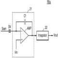
도 11은 도 10의 수신기(RX)일 구현 예를 나타내는 회로도이다.FIG. 11 is a circuit diagram illustrating an implementation example of a receiver (RX) of FIG. 10 .
도 11을 참조하면, 수신기(RXa)는 차지 앰프(21), 및 적분기(22)를 포함할 수 있다. 차지 앰프(21)는 증폭기(AMP) 및 피드백 커패시터(Cf)를 포함할 수 있다. 증폭기(AMP)는 센싱 노드(SN)에 연결되는 제1 입력 단자, 입력 전압(Vin)을 수신하는 제2 입력 단자, 및 센싱 전압을 출력하는 출력 단자를 가질 수 있다. 피드백 커패시터(Cf)는 제1 입력 단자와 출력 단자 사이에 연결될 수 있다. 차지 앰프(21)는 수신되는 센싱 신호(Ssen), 예컨대 전류 신호를 증폭 및 변환하여, 센싱 전압을 출력할 수 있다. 적분기(22)는 차지 앰프(21)로부터 출력되는 센싱 전압을 적분(또는, 누적)할 수 있다. 예를 들어, 적분기(11)는 컨트롤러(도 3의 210)의 제어에 따라 적어도 두 번 이상 적분 동작을 수행할 수 있다. 적분기(11)는 적분된 전압(Vout)을 아날로그 터치 값으로서 출력할 수 있다. 도 4의 ADC(222)는 아날로그 터치 값을 디지털 값을 변환한 터치 데이터를 출력할 수 있다.Referring to FIG. 11 , the receiver RXa may include a
계속하여 도 10을 참조하면, 복수의 송신기(TX)는 터치 센싱 어레이(110a)의 로우 채널들(예컨대 R1 내지 R7)에 각각 연결될 수 있으며, 복수의 수신기(RX)는 터치 센싱 어레이(110a)의 칼럼 채널들(예컨대 C1 내지 C5)에 각각 연결될 수 있다. 로우 채널들(예컨대 R1 내지 R7)은 구동 채널들이고, 칼럼 채널들(예컨대 C1 내지 C5)은 수신 채널들일 수 있다. 그러나 이에 제한되는 것은 아니며, 다른 실시예에 있어서, 복수의 송신기(TX)는 터치 센싱 어레이(110a)의 칼럼 채널들(예컨대 C1 내지 C5)에 각각 연결될 수 있으며, 복수의 수신기(RX)는 터치 센싱 어레이(110a)의 로우 채널들(예컨대 R1 내지 R7)에 각각 연결될 수 있다. 본 실시예에 따른 AFE(221a)는 상호 정전용량 센싱 방식 또는 자기 정전용량 센싱 방식으로 터치 센싱 어레이(110a)를 센싱할 수 있다. 이하, 본 개시의 실시예에 따른 상호 정전용량 센싱 방식 및 자기 정전용량 센싱 방식에 대하여 설명하기로 한다.Referring to FIG. 10 , a plurality of transmitters TX may be respectively connected to row channels (eg, R1 to R7) of the
도 12는 상호 정전 용량 센싱 방식을 설명하는 도면이다.12 is a diagram for explaining a mutual capacitance sensing method.
도 12를 참조하면, 송신기(TX)가 구동 신호(Sdrv)를 구동 채널들(예컨대 로우 채널들(R1 내지 R7))에 전송하면, 구동 채널에 연결된 제1 센싱 전극(SE1)(예컨대 구동 전극)과 제2 센싱 전극(SE2) 사이의 상호 정전용량(Cm)에 대응하는 센싱 신호(Ssen)가 출력될 수 있다. 이 때, 제2 센싱 전극(SE2)은 로우 센싱 전극(SE1)과 인접하게 배치되며, 수신 채널(예컨대 칼럼 채널들(예컨대 C1 내지 C5))에 연결되는 전극이다. 수신기의 채널 증폭기(21)는 센싱 신호(Ssen)를 증폭 및 변환하여 센싱 전압을 출력할 수 있다. 오브젝트가 제1 센싱 전극(SE1) 및 제2 센싱 전극(SE1)에 접촉하거나 근접하게 되면, 상호 정전용량(Cm)은 감소될 수 있으며, 이에 따라서, 센싱 신호(Ssen)가 변화하게 된다. 센싱 신호(Ssen)의 변화 정도를 기초로 터치 값이 생성될 수 있다.Referring to FIG. 12 , when the transmitter TX transmits the driving signal Sdrv to the driving channels (eg, the low channels R1 to R7), the first sensing electrode SE1 (eg, the driving electrode) connected to the driving channel ) and the second sensing electrode SE2 , the sensing signal Ssen corresponding to the mutual capacitance Cm may be output. In this case, the second sensing electrode SE2 is disposed adjacent to the row sensing electrode SE1 and is an electrode connected to a receiving channel (eg, column channels (eg, C1 to C5)). The
도 13a 및 도 13b는 본 개시의 실시예에 따른 상호 정전용량 센싱 방식을 나타낸다.13A and 13B show a mutual capacitance sensing method according to an embodiment of the present disclosure.
도 13a 및 도 13b를 참조하면, 송신부(20a)는 복수의 구동 신호(Sdrv1 내지 Sdrv7)를 T1 내지 T7 구간에 차례로 로우 채널들(R1 내지 R7)에 인가하고, 수신부(30a)는 제1 로우 채널(R1)에 인가된 제1 구동 신호(Sdrv1)를 기초로 생성되는 센싱 신호들부터 제7 로우 채널(R7)에 인가된 제7 구동 신호(Sdrv7)를 기초로 생성되는 센싱 신호들까지 차례로 수신함으로써, 터치 센싱을 수행할 수 있다.Referring to FIGS. 13A and 13B , the
도 13a를 참조하면, 제1 프레임 구간(FRAME1)에는 제1 극성(+)을 갖는 복수의 구동 신호(Sdrv1 내지 Sdrv7)가 터치 센싱 어레이(110a)의 로우 채널들(R1 내지 R7)에 인가되고, 도 13b를 참조하면, 제2 프레임 구간(FRAME2)에는 제2 극성(-)을 갖는 복수의 구동 신호(Sdrv1 내지 Sdrv7)가 터치 센싱 어레이(110a)의 로우 채널들(R1 내지 R7)에 인가될 수 있다.Referring to FIG. 13A , in the first frame period FRAME1, a plurality of drive signals Sdrv1 to Sdrv7 having a first polarity (+) are applied to the low channels R1 to R7 of the
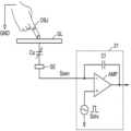
도 14는 자기 정전용량 센싱 방식을 설명하는 도면이다.14 is a diagram illustrating a self-capacitance sensing method.
도 14를 참조하면, 센싱 전극(SE)에 오브젝트(OBJ)가 접촉 또는 근접하면, 센싱 전극(SE)의 자기 정전용량(Cs)이 증가하게 된다. 수신기의 채널 증폭기(21)의 제2 입력 단자에 구동 신호(Sdrv)가 입력 신호로서 인가되면, 제1 입력 단자와 제2 입력 단자는 동 전위를 가지게 되므로, 제1 입력 단자를 통해서 센싱 전극(SE)에 구동 신호(Sdrv)가 제공되어, 자기 정전용량(Cs)에 대응하는 센싱 신호(Ssen)가 출력된다. 채널 증폭기(21)는 센싱 신호(Ssen)를 증폭 및 변환하여 센싱 전압을 출력할 수 있다.Referring to FIG. 14 , when the object OBJ contacts or approaches the sensing electrode SE, the self capacitance Cs of the sensing electrode SE increases. When the driving signal Sdrv is applied as an input signal to the second input terminal of the
도 15a 및 도 15b는 본 개시의 실시예에 따른 자기 정전용량 센싱 방식을 나타낸다.15A and 15B show a self-capacitance sensing method according to an embodiment of the present disclosure.
도 15a 및 도 15b를 참조하면, 터치 센싱 어레이(110a)의 로우 채널들(R1 내지 R7) 및 칼럼 채널들(C1 내지 C5)에 수신기(RX)가 연결될 수 있다. 도 14를 참조하여 설명한 바와 같이, 수신기(RX)는 송신 및 수신 동작을 수행할 수 있다.Referring to FIGS. 15A and 15B , the receiver RX may be connected to row channels R1 to R7 and column channels C1 to C5 of the
T1 구간에는 로우 채널들(R1 내지 R7)에 구동 신호(Sdrv)가 동시에 인가됨으로써, 로우 채널들(R1 내지 R7)이 센싱될 수 있다. T2 구간에는 칼럼 채널들(C1 내지 C5)에 구동 신호(Sdrv)가 동시에 인가됨으로써, 칼럼 채널들(C1 내지 C5)이 센싱될 수 있다.In the period T1, the driving signal Sdrv is simultaneously applied to the low channels R1 to R7, so that the low channels R1 to R7 can be sensed. In the period T2, the column channels C1 to C5 may be sensed by simultaneously applying the driving signal Sdrv to the column channels C1 to C5.
도 15a를 참조하면, 제1 프레임 구간(FRAME1)에는 T1 구간에 제1 극성(+)을 갖는 구동 신호(Sdrv)가 로우 채널들(R1 내지 R7)에 인가되고, T2 구간에 제1 극성(+)을 갖는 구동 신호(Sdrv)가 칼럼 채널들(C1 내지 C5)에 인가될 수 있다.Referring to FIG. 15A , in a first frame period FRAME1, a driving signal Sdrv having a first polarity (+) is applied to low channels R1 to R7 in a period T1, and a first polarity ( The driving signal Sdrv having +) may be applied to the column channels C1 to C5.
도 15b를 참조하면, 제2 프레임 구간(FRAME2)에는 T1 구간에 제2 극성(-)을 갖는 구동 신호(Sdrv)가 로우 채널들(R1 내지 R7)에 인가되고, T2 구간에 제2 극성(-)을 갖는 구동 신호(Sdrv)가 칼럼 채널들(C1 내지 C5)에 인가될 수 있다.15B, in the second frame period FRAME2, the driving signal Sdrv having the second polarity (-) is applied to the low channels R1 to R7 in the period T1, and the second polarity ( The driving signal Sdrv having -) may be applied to the column channels C1 to C5.
도 16a 및 도 16b는 본 개시의 실시예에 따른 상호 정전용량 센싱 방식에 인가되는 구동 신호들의 예를 나타낸다. 설명의 편의를 위하여, 터치 센싱 어레이의 일부 로우 채널들(R1 내지 R4) 및 상기 일부 로우 채널들(R1 내지 R4)에 인가되는 구동 신호들(Sdrv1 내지 Sdrv4)을 도시한다.16A and 16B show examples of driving signals applied to a mutual capacitance sensing method according to an embodiment of the present disclosure. For convenience of description, some row channels R1 to R4 of the touch sensing array and driving signals Sdrv1 to Sdrv4 applied to the some row channels R1 to R4 are illustrated.
도 16a 및 도 16b를 참조하면, 송신부(20a)는 복수의 구동 신호(Sdrv1 내지 Sdrv4)를 T1 내지 T4 구간에 차례로 로우 채널들(R1 내지 R4)에 인가할 수 있다. 도 16a를 참조하면, 제1 프레임 구간(FRAME1)에 제1 극성(+)을 가지는 제1 구동 신호(Sdrv1) 및 제3 구동 신호(Sdrv3)가 제1 로우 채널(R1) 및 제3 로우 채널(R3)에 각각 인가되고, 제2 극성(-)을 가지는 제2 구동 신호(Sdrv2) 및 제4 구동 신호(Sdrv4)가 제2 로우 채널(R2) 및 제4 로우 채널(R4)에 각각 인가될 수 있다. 즉, 인접한 로우 채널들에 서로 다른 극성을 가지는 구동 신호들이 인가될 수 있다.Referring to FIGS. 16A and 16B , the
도 16b를 참조하면, 제2 프레임 구간(FRAME2)에 구동 신호들의 극성이 변경되어, 제2 극성(-)을 가지는 제1 구동 신호(Sdrv1) 및 제3 구동 신호(Sdrv3)가 제1 로우 채널(R1) 및 제3 로우 채널(R3)에 각각 인가되고, 제1 극성(+)을 가지는 제2 구동 신호(Sdrv2) 및 제4 구동 신호(Sdrv4)가 제2 로우 채널(R2) 및 제4 로우 채널(R4)에 각각 인가될 수 있다.Referring to FIG. 16B, the polarities of the driving signals are changed in the second frame period FRAME2, so that the first driving signal Sdrv1 and the third driving signal Sdrv3 having a second polarity (-) are configured as the first low channel. The second driving signal Sdrv2 and the fourth driving signal Sdrv4, which are respectively applied to R1 and the third low channel R3 and have a first polarity (+), are applied to the second low channel R2 and the fourth driving signal Sdrv4. Each may be applied to the low channel R4.
도 17a 및 도 17b는 본 개시의 실시예에 따른 멀티 구동 방식을 나타낸다.17A and 17B show a multi-driving method according to an embodiment of the present disclosure.
설명의 편의를 위하여, 터치 센싱 어레이의 일부 로우 채널들(R1 내지 R4) 및 상기 일부 로우 채널들(R1 내지 R4) 에 인가되는 구동 신호들(Sdrv1 내지 Sdrv4)을 도시한다.For convenience of explanation, some row channels R1 to R4 of the touch sensing array and driving signals Sdrv1 to Sdrv4 applied to the some row channels R1 to R4 are illustrated.
도 17a 및 도 17b를 참조하면, T1 구간 및 T2 구간에 제1 구동 신호(Sdrv1) 및 제2 구동 신호(Sdrv2)가 동시에 제1 로우 채널(R1) 및 제2 로우 채널(R2)에 인가되고, T3 구간 및 T4 구간에 제3 구동 신호(Sdrv3) 및 제4 구동 신호(Sdrv4)가 동시에 제3 로우 채널(R3) 및 제2 로우 채널(R4)에 인가될 수 있다.17A and 17B, the first driving signal Sdrv1 and the second driving signal Sdrv2 are simultaneously applied to the first low channel R1 and the second low channel R2 in the period T1 and T2, , the third driving signal Sdrv3 and the fourth driving signal Sdrv4 may be simultaneously applied to the third low channel R3 and the second low channel R4 in the period T3 and T4.
도 17a를 참조하면, 제1 프레임 구간(FRAME1)에 인가되는 제1 구동 신호(Sdrv1) 및 제2 구동 신호(Sdrv2)는 일부 구간의 극성이 동일하고, 다른 일부 구간의 극성이 상이할 수 있다. 예컨대, T1 구간에 제1 구동 신호(Sdrv1) 및 제2 구동 신호(Sdrv2)는 제1 극성(+)을 가지며, T2 구간에 제1 구동 신호(Sdrv1)은 제1 극성(+)을 가지고, 제2 구동 신호(Sdrv2)는 제2 극성(-)을 가질 수 있다. 제3 구동 신호(Sdrv3) 및 제4 구동 신호(Sdrv4) 또한 일부 구간의 극성이 동일하고, 다른 일부 구간의 극성이 상이할 수 있다.Referring to FIG. 17A , the first driving signal Sdrv1 and the second driving signal Sdrv2 applied to the first frame period FRAME1 may have the same polarity in some sections and different polarities in other sections. . For example, in the period T1, the first driving signal Sdrv1 and the second driving signal Sdrv2 have a first polarity (+), and in the period T2, the first driving signal Sdrv1 has a first polarity (+), The second driving signal Sdrv2 may have a second polarity (-). The third driving signal Sdrv3 and the fourth driving signal Sdrv4 may also have the same polarity in some sections and different polarities in other sections.
도 17b를 참조하면, 제2 프레임 구간(FRAME2)에 인가되는 제1 내지 제4 구동 신호들(Sdrv1 내지 Sdrv1)의 극성은 제1 프레임 구간(FRAME1)과 상이하다. 예컨대, T1 구간에 제1 구동 신호(Sdrv1) 및 제2 구동 신호(Sdrv2)는 제2 극성(-)을 가지며, T2 구간에 제1 구동 신호(Sdrv1)는 제2 극성(-)을 가지고, 제2 구동 신호(Sdrv2)는 제1 극성(+)을 가질 수 있다. 제3 구동 신호(Sdrv3) 및 제4 구동 신호(Sdrv4) 또한 제1 프레임 구간(FRMAE1)과 반대의 극성을 가질 수 있다.Referring to FIG. 17B , polarities of the first to fourth driving signals Sdrv1 to Sdrv1 applied to the second frame period FRAME2 are different from those of the first frame period FRAME1 . For example, in the period T1, the first driving signal Sdrv1 and the second driving signal Sdrv2 have a second polarity (-), and in the period T2, the first driving signal Sdrv1 has a second polarity (-), The second driving signal Sdrv2 may have a first polarity (+). The third driving signal Sdrv3 and the fourth driving signal Sdrv4 may also have opposite polarities to those of the first frame period FRMAE1.
동시에 로우 채널들에 구동 신호들이 인가되는 경우, 센싱 신호들은 동시에 인가된 구동 신호들의 성분을 모두 포함하게 된다. 그러나, 인가되는 구동 신호들의 일부 구간의 극성이 상이하므로, 즉, 구동 신호들의 코드가 상이하므로, 센싱 신호들에 기초하여 생성되는 터치 데이터 값들이 도출되면, 프로세서(230)는 코드 값을 기초로 터치 데이터 값들을 디코딩 함으로써, 구동 신호들의 각각에 대응하는 터치 데이터 값들을 산출할 수 있다. 이와 같은 멀티 구동 방식에 따라 터치 센싱을 수행함에 있어서, 도 17a 및 도 17b를 참조하여 설명한 바와 같이, 프레임이 변함에 따라 구동 신호들의 극성을 반대로 변경하는 본 개시의 실시예에 따른 터치 센싱 방법이 적용될 수 있다.When driving signals are simultaneously applied to the row channels, the sensing signals include all components of the simultaneously applied driving signals. However, since the polarities of some sections of the applied driving signals are different, that is, the codes of the driving signals are different, when touch data values generated based on the sensing signals are derived, the
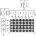
도 18a 및 도 18b는 본 개시의 실시예에 따른, 닷 센서를 포함하는 터치 센싱 어레이에 대한 터치 센싱 방법을 나타낸다.18A and 18B illustrate a touch sensing method for a touch sensing array including a dot sensor according to an embodiment of the present disclosure.
도 18a 및 도 18b를 참조하면, 센싱 전극(SE)들, 예컨대 닷 센서들은 칼럼 단위로 동일한 멀티플랙서(MUX)에 연결될 수 있으며, 멀티플래서(MUX)에서 선택된 센싱 전극(SE)이 수신기(RX)와 전기적으로 연결될 수 있다. 멀티플랙서(MUX)는 도 4의 컨트롤러(210)의 제어 하에, 로우 단위로 센싱 전극들(SE)을 수신기들(RX)에 연결할 수 있다. 멀티플랙서(MUX)에 의하여 선택된 센싱 전극에는 수신기(RX)를 통해서 구동 신호(Sdrv)가 인가되고, 구동 신호(Sdrv)에 기초하여 생성되는 센싱 신호가 수신기(RX)로 출력될 수 있다.18A and 18B, sensing electrodes SE, for example, dot sensors, may be connected to the same multiplexer MUX in units of columns, and the sensing electrode SE selected from the multiplexer MUX may be connected to a receiver ( RX) can be electrically connected. The multiplexer MUX may connect the sensing electrodes SE to the receivers RX in a row unit under the control of the
도 18a를 참조하면, 제1 프레임 구간(FRAME1)의 T1 내지 T4 구간에 제1 극성(+)의 구동 신호(Sdrv)가 센싱 전극(SE)에 인가될 수 있다. 예를 들어서, T1 내지 T4 구간에 제1 로우부터 제4 로우까지 차례로 제1 극성(+)의 구동 신호(Sdrv)가 인가될 수 있다.Referring to FIG. 18A , the driving signal Sdrv of the first polarity (+) may be applied to the sensing electrode SE in the period T1 to T4 of the first frame period FRAME1 . For example, the first polarity (+) driving signal Sdrv may be sequentially applied from the first row to the fourth row in the period T1 to T4.
도 18b를 참조하면, 제2 프레임 구간(FRAME2)의 T1 내지 T4 구간에 제2 극성(-)의 구동 신호(Sdrv)가 센싱 전극(SE)에 인가될 수 있다. 예를 들어서, T1 내지 T4 구간에 제1 로우부터 제4 로우까지 차례로 제2 극성(-)의 구동 신호(Sdrv)가 인가될 수 있다.Referring to FIG. 18B , the driving signal Sdrv of the second polarity (−) may be applied to the sensing electrode SE in the period T1 to T4 of the second frame period FRAME2 . For example, the driving signal Sdrv of the second polarity (-) may be sequentially applied from the first row to the fourth row in the period T1 to T4.
이와 같이, 프레임의 변경에 따라 구동 신호의 극성을 변경하는 본 개시의 실시예에 따른 터치 센싱 방법은 닷 센서를 포함하는 터치 센싱 어레이(110b)의 터치 센싱 수행 시 적용될 수 있다.As such, the touch sensing method according to the exemplary embodiment of the present disclosure in which the polarity of the driving signal is changed according to a frame change may be applied when the
도 19는 본 개시의 실시예에 따른 터치 컨트롤러의 터치 센싱 방법을 나타내는 흐름도이다. 전술한 다양한 실시예들은 본 실시예의 터치 센싱 방법에 적용될 수 있다.19 is a flowchart illustrating a touch sensing method of a touch controller according to an exemplary embodiment of the present disclosure. Various embodiments described above may be applied to the touch sensing method of the present embodiment.
도 19를 참조하면, 터치 컨트롤러는, 제1 디스플레이 프레임 구간에 제1 구동 신호를 기초로 터치 센싱 어레이(도 1의 110)를 구동 및 센싱할 수 있다(S10). 터치 컨트롤러는 DDI로부터 제공되는 디스플레이 타이밍 신호(도 1의 Tsig)에 동기하여 터치 센싱 어레이를 구동 및 센싱할 수 있으며, 디스플레이 타이밍 신호(Tsig)를 기초로 디스플레이 패널(도1의 120)에 표시되는 이미지 프레임, 즉 디스플레이 프레임을 판단할 수 있다. 터치 컨트롤러는 제1 디스플레이 프레임 구간에 제1 구동 신호를 생성하고, 제1 구동 신호를 기초로 터치 센싱 동작을 수행할 수 있다.Referring to FIG. 19 , the touch controller may drive and sense the touch sensing array ( 110 of FIG. 1 ) based on the first driving signal in the first display frame period ( S10 ). The touch controller may drive and sense the touch sensing array in synchronization with the display timing signal (Tsig in FIG. 1) provided from the DDI, and display the display timing signal (120 in FIG. 1) on the display panel (120 in FIG. 1) based on the display timing signal (Tsig). An image frame, i.e., a display frame, may be determined. The touch controller may generate a first driving signal in the first display frame period and perform a touch sensing operation based on the first driving signal.
이후, 터치 컨트롤러는, 제2 디스플레이 프레임 구간에 제1 구동 신호와 반대 극성의 제2 구동 신호를 기초로 터치 센싱 어레이를 구동 및 센싱할 수 있다(S20). 터치 컨트롤러는 제2 디스플레이 프레임 구간에 제1 구동 신호와 반대 극성되는 극성을 갖는 제2 구동 신호를 생성하고, 제2 구동 신호를 기초로 터치 센싱 동작을 수행할 수 있다. 제1 구동 신호 및 제2 구동 신호는 펄스 신호일 수 있으며, 180도의 위상 차이를 가질 수 있다. 실시예에 있어서, 제1 구동 신호 및 제2 구동 신호의 주파수는 동일할 수 있다. 이와 같이, 본 개시의 실시예에 따른 터치 컨트롤러는 디스플레이 프레임 구간이 변경됨에 따라서, 구동 신호의 극성을 변경할 수 있다.Thereafter, the touch controller may drive and sense the touch sensing array based on the second driving signal having an opposite polarity to the first driving signal in the second display frame period (S20). The touch controller may generate a second driving signal having a polarity opposite to that of the first driving signal in the second display frame period and perform a touch sensing operation based on the second driving signal. The first driving signal and the second driving signal may be pulse signals and may have a phase difference of 180 degrees. In an embodiment, the frequency of the first driving signal and the second driving signal may be the same. As such, the touch controller according to an embodiment of the present disclosure may change the polarity of the driving signal as the display frame section changes.
도 20은 도 19의 터치 센싱 방법의 일 구현예를 나타내는 흐름도이다.20 is a flowchart illustrating an implementation example of the touch sensing method of FIG. 19 .
한 번의 터치 센싱 수행 시, 예컨대, 한 번의 터치 좌표 산출 시, 다양한 센싱 모드(센싱 방식)에 따라서, 복수 번 터치 센싱 어레이를 구동 및 센싱할 수 있다.When performing touch sensing once, for example, when calculating touch coordinates once, the touch sensing array may be driven and sensed a plurality of times according to various sensing modes (sensing methods).
도 20을 참조하면, 제1 디스플레이 프레임 구간에 제1 구동 신호를 기초로 터치 센싱 수행 시(S10a), 제1 센싱 방식에 기초하여 터치 센싱 어레이를 구동 및 센싱하고(S11) 이후, 제2 센싱 방식에 기초하여 터치 센싱 어레이를 구동 및 센싱할 수 있다(S12).Referring to FIG. 20 , when touch sensing is performed based on a first driving signal in a first display frame period (S10a), the touch sensing array is driven and sensed based on the first sensing method (S11), and then second sensing Based on the method, the touch sensing array may be driven and sensed (S12).
이와 반대로, 제2 디스플레이 프레임 구간에 제2 구동 신호를 기초로 터치 센싱 수행 시(S30a), 제3 센싱 방식에 기초하여 터치 센싱 어레이를 구동 및 센싱하고(S31) 이후, 제2 센싱 방식에 기초하여 터치 센싱 어레이를 구동 및 센싱할 수 있다(S32).Conversely, when touch sensing is performed based on the second driving signal in the second display frame period (S30a), the touch sensing array is driven and sensed based on the third sensing method (S31), and then based on the second sensing method. to drive and sense the touch sensing array (S32).
이와 같이, 본 개시의 실시예에 따른 터치 센싱 방법에 따르면, 디스플레이 프레임이 변경됨에 따라서, 구동 신호의 극성을 변경하고, 각 프레임 구간마다 센싱 방식들이 적용되는 순서를 변경할 수 있다.As described above, according to the touch sensing method according to an embodiment of the present disclosure, as the display frame is changed, the polarity of the driving signal may be changed, and the order in which sensing methods are applied may be changed for each frame period.
도 21은 본 개시의 실시예에 따른 스마트폰을 나타내는 도면이다.21 is a diagram illustrating a smart phone according to an embodiment of the present disclosure.
도 21을 참조하면, 스마트폰(2000)은 터치 스크린(2100), 터치 스크린 구동 회로(2200) 및 하우징(2500)을 포함할 수 있다. 스마트폰(2000)은 또한, 스마트폰(2000)의 전반적인 동작을 제어하는 AP를 포함할 수 있다.Referring to FIG. 21 , a
하우징(2500)은 스마트폰(2000)의 외관을 형성할 수 있으며, 외부 충격 또는 스크래치로부터 스마트폰(2000) 내부의 구성들, 예컨대 집적 회로들, 배터리, 안테나 등을 보호할 수 있다. 터치 스크린 구동 회로(2200)는 하우징(2500) 내부에 배치될 수 있다.The housing 2500 may form the exterior of the
터치 스크린(2100)은 디스플레이, 터치 센싱을 터치 센싱 장치(1000)의 입/출력 장치로서 동작할 수 있다. 실시예에 있어서, 터치 스크린(2100)은 터치 입력의 압력(force)을 센싱할 수 있다. 터치 스크린 구동 회로(2200)는 터치 스크린(2100)의 디스플레이 및 터치 센싱 동작을 제어할 수 있다.The touch screen 2100 may operate as a display and touch sensing input/output device of the
도 1을 참조하여 설명한 터치 스크린 장치(1000)의 터치 스크린(100) 및 구동 집적 회로(DIC), 즉 도 1의 DDI(300) 및 터치 컨트롤러(200)가 본 실시예의 스마트폰(2000)에 적용될 수 있다. DDI(300) 및 터치 컨트롤러(200)는 터치 스크린 구동 회로(2200)에 적용될 수 있다.The
DDI(300)는 디스플레이 타이밍 신호를 터치 컨트롤러(200)에 제공하고, 터치 컨트롤러(200)는 디스플레이 타이밍 신호에 동기하여 디스플레이 노이즈 발생량이 적은 구간에 터치 센싱을 수행할 수 있다. 또한, 터치 컨트롤러(200)는 도 1 내지 도 20을 참조하여 전술한 바와 같이, 디스플레이 프레임이 변경됨에 따라서, 구동 신호(Sdrv)의 극성을 변경함으로써, 터치 센싱이 디스플레이 타이밍 신호에 동기하여 수행되는 것에 기인하는 화질 열화를 방지할 수 있다. 따라서, 화질 열화 없이, 스마트폰(2000)의 터치 센싱 감도가 향상될 수 있다.The
본 개시는 도면에 도시된 실시예를 참고로 설명되었으나 이는 예시적인 것에 불과하며, 본 기술 분야의 통상의 지식을 가진 자라면 이로부터 다양한 변형 및 균등한 다른 실시예가 가능하다는 점을 이해할 것이다. 따라서, 본 개시의 진정한 기술적 보호 범위는 첨부된 특허청구범위의 기술적 사상에 의하여 정해져야 할 것이다.Although the present disclosure has been described with reference to the embodiments shown in the drawings, this is only exemplary, and those skilled in the art will understand that various modifications and equivalent other embodiments are possible therefrom. Therefore, the true technical scope of protection of the present disclosure should be determined by the technical spirit of the appended claims.
100: 터치 스크린 110,110a, 110b: 터치 센싱 어레이
120: 디스플레이 패널 200: 터치 컨트롤러
300: DDI100:
120: display panel 200: touch controller
300: DDI
Claims (20)
Translated fromKorean상기 터치 센싱 제어 신호를 기초로 터치 센싱 어레이를 구동하고 상기 터치 센싱 어레이로부터 출력되는 센싱 신호들을 기초로 터치 데이터를 생성하며, 디스플레이 패널에 제1 프레임의 영상이 표시되는 제1 디스플레이 프레임 구간에 제1 구동 신호를 상기 터치 센싱 어레이의 채널들에 제공하고, 상기 디스플레이 패널에 제2 프레임의 영상이 표시되는 제2 디스플레이 프레임 구간에 상기 제1 구동 신호와 반대 극성의 제2 구동 신호를 상기 채널들에 제공하는 센싱 회로를 포함하는 터치 컨트롤러.a controller receiving a display timing signal and generating a touch sensing control signal in synchronization with the display timing signal; and
A touch sensing array is driven based on the touch sensing control signal, touch data is generated based on sensing signals output from the touch sensing array, and a first frame is displayed on a display panel during a first display frame period. 1. A driving signal is provided to channels of the touch sensing array, and a second driving signal having a polarity opposite to that of the first driving signal is applied to the channels in a second display frame period in which an image of a second frame is displayed on the display panel. A touch controller including a sensing circuit provided to.
상기 제1 구동 신호 및 상기 제2 구동 신호를 하나 또는 두 개의 디스플레이 프레임 구간마다 교번적으로 구동 전극에 제공하는 것을 특징으로 하는 터치 컨트롤러.The method of claim 1, wherein the sensing circuit,
The touch controller characterized in that the first driving signal and the second driving signal are alternately provided to the driving electrode every one or two display frame sections.
디스플레이 패널을 구동하는 디스플레이 구동 회로로부터 제공되는 수직 동기 신호 및 수평 동기 신호 중 적어도 하나를 포함하는 것을 특징으로 하는 터치 컨트롤러.The method of claim 1, wherein the display timing signal,
A touch controller comprising at least one of a vertical synchronization signal and a horizontal synchronization signal provided from a display driving circuit that drives a display panel.
하나의 디스플레이 프레임 구간에 상기 터치 센싱 어레이를 적어도 2회 구동하는 것을 특징으로 하는 터치 컨트롤러.The method of claim 1, wherein the sensing circuit,
A touch controller characterized in that driving the touch sensing array at least twice in one display frame period.
하나의 디스플레이 프레임 구간에 제1 센싱 모드 및 제2 센싱 모드에 기초하여 상기 터치 센싱 어레이를 적어도 2회 구동하며,
상기 제1 센싱 모드 및 상기 제2 센싱 모드에는 상호 정전용량 센싱 방식, 자기 정전용량 센싱 방식 및 터치 압력 센싱 방식 중 서로 다른 하나의 센싱 방식이 적용되는 것을 특징으로 하는 터치 컨트롤러.The method of claim 1, wherein the sensing circuit,
Driving the touch sensing array at least twice based on a first sensing mode and a second sensing mode in one display frame period;
The touch controller of claim 1 , wherein a different one of a mutual capacitance sensing method, a self capacitance sensing method, and a touch pressure sensing method is applied to the first sensing mode and the second sensing mode.
매 프레임 구간마다 상기 제1 센싱 모드 및 상기 제2 센싱 모드가 적용되는 순서를 변경하는 것을 특징으로 하는 터치 컨트롤러.The method of claim 7, wherein the sensing circuit,
The touch controller, characterized in that changing the order in which the first sensing mode and the second sensing mode are applied for every frame period.
상기 하나의 디스플레이 프레임 구간에, 상기 센싱 회로로부터 출력되는 제1 터치 데이터 및 제2 터치 데이터를 기초로 터치 좌표를 산출하는 프로세서를 더 포함하는 것을 특징으로 하는 터치 컨트롤러.According to claim 7,
and a processor calculating touch coordinates based on first touch data and second touch data output from the sensing circuit in the one display frame period.
상기 터치 센싱 제어 신호를 기초로, 상기 제1 구동 신호 또는 상기 제2 구동 신호를 생성하는 구동 신호 생성기; 및
상기 제1 구동 신호 또는 상기 제2 구동 신호를 상기 터치 센싱 어레이의 제1 채널들에 제공하고, 상기 제1 채널들로부터 상기 센싱 신호들을 수신하는 수신기들을 포함하는 것을 특징으로 하는 터치 컨트롤러.The method of claim 1, wherein the sensing circuit,
a driving signal generator configured to generate the first driving signal or the second driving signal based on the touch sensing control signal; and
and receivers providing the first driving signal or the second driving signal to first channels of the touch sensing array and receiving the sensing signals from the first channels.
상기 터치 센싱 제어 신호를 기초로, 상기 제1 구동 신호 또는 상기 제2 구동 신호를 생성하는 구동 신호 생성기;
상기 제1 구동 신호 또는 상기 제2 구동 신호를 상기 터치 센싱 어레이의 구동 채널들에 제공하는 송신기들; 및
상기 터치 센싱 어레이의 센싱 채널들로부터 상기 센싱 신호들을 수신하는 수신기들을 포함하는 것을 특징으로 하는 터치 컨트롤러.The method of claim 1, wherein the sensing circuit,
a driving signal generator configured to generate the first driving signal or the second driving signal based on the touch sensing control signal;
transmitters providing the first driving signal or the second driving signal to driving channels of the touch sensing array; and
and receivers receiving the sensing signals from sensing channels of the touch sensing array.
상기 제1 디스플레이 구동 구간에, 상기 터치 센싱 어레이의 제1 구동 채널 및 제2 구동 채널에 각각 상기 제1 구동 신호 및 제3 구동 신호를 동시에 제공하고,
상기 제2 디스플레이 구동 구간에, 상기 제1 구동 채널 및 상기 제2 구동 채널에 각각 상기 제2 구동 신호 및 제4 구동 신호를 동시에 제공하며,
상기 제1 구동 신호의 일부 구간과 상기 제3 구동 신호의 일부 구간의 극성이 서로 반대이며, 상기 제3 구동 신호와 상기 제4 구동 신호의 극성이 반대인 것을 특징으로 하는 터치 컨트롤러.The method of claim 1, wherein the sensing circuit,
In the first display driving period, simultaneously providing the first driving signal and the third driving signal to the first driving channel and the second driving channel of the touch sensing array, respectively;
In the second display driving period, the second driving signal and the fourth driving signal are simultaneously provided to the first driving channel and the second driving channel, respectively;
The touch controller of claim 1 , wherein polarities of partial sections of the first driving signal and partial sections of the third driving signal are opposite to each other, and polarities of the third driving signal and the fourth driving signal are opposite to each other.
상기 디스플레이 패널을 구동하는 디스플레이 구동 회로로부터 제공되는 동기 신호에 기초하여 터치 센싱 어레이를 구동하며, 상기 디스플레이 패널에 한 프레임의 영상이 표시되는 디스플레이 프레임 구간이 변경됨에 따라서, 상기 터치 센싱 어레이의 상기 전극들에 제공되는 구동 신호들의 극성을 변경하는 터치 컨트롤러를 포함하는 터치 센싱 장치.a touch sensing array stacked on the display panel and including electrodes for sensing a touch input; and
A touch sensing array is driven based on a synchronization signal provided from a display driving circuit that drives the display panel, and as a display frame section in which an image of one frame is displayed on the display panel is changed, the electrode of the touch sensing array A touch sensing device including a touch controller that changes the polarity of drive signals provided to them.
상기 구동 신호들의 극성을 제1 극성에서 제2 극성으로 변경하거나 또는 상기 제2 극성에서 상기 제1 극성으로 변경하며, 상기 제1 극성을 갖는 제1 구동 신호와 상기 제2 극성을 갖는 제2 구동 신호의 위상 차이는 180도인 것을 특징으로 하는 터치 센싱 장치.14. The method of claim 13, wherein the touch controller,
The polarity of the driving signals is changed from a first polarity to a second polarity or from the second polarity to the first polarity, and the first driving signal having the first polarity and the second driving signal having the second polarity The touch sensing device, characterized in that the phase difference of the signal is 180 degrees.
상기 디스플레이 프레임 구간이 N번(N은 양의 정수) 변경될 때마다 상기 구동 신호들의 상기 극성을 변경하는 것을 특징으로 하는 터치 센싱 장치.14. The method of claim 13, wherein the touch controller,
The touch sensing device, characterized in that changing the polarity of the driving signals every time the display frame period is changed N times (N is a positive integer).
상기 프레임이 표시되는 한 프레임 구간에, 복수의 센싱 모드에 따라서 상기 터치 센싱 어레이를 복수 번 구동하며, 상기 프레임이 변경됨에 따라서 상기 복수의 센싱 모드가 적용되는 순서를 변경하는 것을 특징으로 하는 터치 센싱 장치.14. The method of claim 13, wherein the touch controller,
Touch sensing characterized by driving the touch sensing array a plurality of times according to a plurality of sensing modes in one frame period in which the frame is displayed, and changing the order in which the plurality of sensing modes are applied as the frame is changed. Device.
터치 컨트롤러가 디스플레이 구동 회로로부터 제공되는 타이밍 신호에 동기하여 디스플레이 패널에 제1 프레임의 영상이 표시되는 제1 디스플레이 프레임 구간에 제1 구동 신호를 기초로 상기 터치 센싱 어레이를 구동 및 센싱하는 제1 터치 센싱 단계; 및
상기 터치 컨트롤러가 상기 타이밍 신호에 동기하여 상기 디스플레이 패널에 제2 프레임의 영상이 표시되는 제2 디스플레이 프레임 구간에 상기 제1 구동 신호와 반대 극성의 제2 구동 신호를 기초로 상기 터치 센싱 어레이를 구동 및 센싱하는 제2 터치 센싱 단계를 포함하는 터치 센싱 방법.A touch sensing method for sensing a touch input generated in a touch sensing array,
A first touch in which a touch controller drives and senses the touch sensing array based on a first driving signal in a first display frame period in which an image of a first frame is displayed on a display panel in synchronization with a timing signal provided from a display driving circuit. sensing step; and
The touch controller drives the touch sensing array based on a second drive signal having an opposite polarity to the first drive signal in a second display frame period in which an image of a second frame is displayed on the display panel in synchronization with the timing signal. and a second touch sensing step of sensing.
상기 제1 터치 센싱 단계는,
제1 센싱 방식에 기초하여 상기 터치 센싱 어레이를 구동한 이후에 제2 센싱 방식에 기초하여 상기 터치 센싱 어레이를 구동하고,
상기 제2 터치 센싱하는 단계는,
상기 제2 센싱 방식에 기초하여 상기 터치 센싱 어레이를 구동한 이후에 상기 제1 센싱 방식에 기초하여 상기 터치 센싱 어레이를 구동하는 것을 특징으로 하는 터치 센싱 방법.According to claim 17,
In the first touch sensing step,
driving the touch sensing array based on a second sensing method after driving the touch sensing array based on a first sensing method;
In the second touch sensing step,
and driving the touch sensing array based on the first sensing method after driving the touch sensing array based on the second sensing method.
상기 제1 터치 센싱 단계 및 상기 제2 터치 센싱 단계는 N 디스플레이 프레임 구간(N은 양의 정수)마다 교번적으로 수행되는 것을 특징으로 하는 터치 센싱 방법.According to claim 17,
Wherein the first touch sensing step and the second touch sensing step are alternately performed every N display frame intervals (N is a positive integer).
Priority Applications (4)
| Application Number | Priority Date | Filing Date | Title |
|---|---|---|---|
| KR1020180034759AKR102534250B1 (en) | 2018-03-26 | 2018-03-26 | Touch screen controller, touch sensing device, and touch sensing method |
| EP19161955.0AEP3547090A1 (en) | 2018-03-26 | 2019-03-11 | Touch controller, touch sensing device, and touch sensing method |
| US16/357,456US11256365B2 (en) | 2018-03-26 | 2019-03-19 | Touch controller, touch sensing device, and touch sensing method |
| CN201910226614.4ACN110362223B (en) | 2018-03-26 | 2019-03-25 | Touch controller, touch sensing device, and touch sensing method |
Applications Claiming Priority (1)
| Application Number | Priority Date | Filing Date | Title |
|---|---|---|---|
| KR1020180034759AKR102534250B1 (en) | 2018-03-26 | 2018-03-26 | Touch screen controller, touch sensing device, and touch sensing method |
Publications (2)
| Publication Number | Publication Date |
|---|---|
| KR20190112593A KR20190112593A (en) | 2019-10-07 |
| KR102534250B1true KR102534250B1 (en) | 2023-05-18 |
Family
ID=65763381
Family Applications (1)
| Application Number | Title | Priority Date | Filing Date |
|---|---|---|---|
| KR1020180034759AActiveKR102534250B1 (en) | 2018-03-26 | 2018-03-26 | Touch screen controller, touch sensing device, and touch sensing method |
Country Status (4)
| Country | Link |
|---|---|
| US (1) | US11256365B2 (en) |
| EP (1) | EP3547090A1 (en) |
| KR (1) | KR102534250B1 (en) |
| CN (1) | CN110362223B (en) |
Families Citing this family (24)
| Publication number | Priority date | Publication date | Assignee | Title |
|---|---|---|---|---|
| KR102534250B1 (en)* | 2018-03-26 | 2023-05-18 | 삼성전자주식회사 | Touch screen controller, touch sensing device, and touch sensing method |
| WO2020154899A1 (en)* | 2019-01-29 | 2020-08-06 | 深圳市汇顶科技股份有限公司 | Pressure calculation method and apparatus using same, electronic device, and touch system |
| KR102764364B1 (en) | 2019-06-12 | 2025-02-07 | 주식회사 하이딥 | Touch apparatus and touch detection method thereof |
| KR102825166B1 (en)* | 2019-10-28 | 2025-06-25 | 엘지디스플레이 주식회사 | Touch driving circuit and touch display device |
| KR102804954B1 (en)* | 2019-12-19 | 2025-05-09 | 주식회사 엘엑스세미콘 | Device and method for touch sensing |
| US11302102B2 (en)* | 2020-01-22 | 2022-04-12 | Novatek Microelectronics Corp. | Method for controlling display panel and control circuit using the same |
| KR102717782B1 (en)* | 2020-02-07 | 2024-10-16 | 삼성전자주식회사 | Electronic device comprising touch sensor ic and method for operating thereof |
| KR102718487B1 (en) | 2020-02-07 | 2024-10-17 | 삼성전자주식회사 | Electronic device comprising touch sensor ic and method for operating thereof |
| CN113811841B (en)* | 2020-03-31 | 2024-03-19 | 京东方科技集团股份有限公司 | Touch circuit, touch panel and display device |
| US11543912B2 (en)* | 2020-04-28 | 2023-01-03 | Novatek Microelectronics Corp. | Touch detection method and touch display device |
| KR102757847B1 (en)* | 2020-07-14 | 2025-01-23 | 삼성디스플레이 주식회사 | Display device and driving method thereof |
| CN113970986B (en)* | 2020-07-23 | 2024-04-12 | 乐金显示有限公司 | Touch display device, touch circuit and touch driving method thereof |
| KR102769009B1 (en)* | 2020-08-04 | 2025-02-19 | 삼성전자주식회사 | Electronic device and method for controlling touch function |
| US11508273B2 (en)* | 2020-11-12 | 2022-11-22 | Synaptics Incorporated | Built-in test of a display driver |
| KR20220067920A (en)* | 2020-11-18 | 2022-05-25 | 삼성전자주식회사 | Touch controller, touch screen driving circuit comprising thereof and operating methof of touch screen driving circuit |
| KR20220077283A (en)* | 2020-12-01 | 2022-06-09 | 삼성디스플레이 주식회사 | Display device |
| KR20220094296A (en)* | 2020-12-28 | 2022-07-06 | 삼성디스플레이 주식회사 | Display device and driving method thereof |
| KR20220112574A (en)* | 2021-02-04 | 2022-08-11 | 삼성전자주식회사 | Touch sensor controller, operating method of touch sensor controller, and touch screen driving circuit |
| US12045418B2 (en)* | 2021-07-06 | 2024-07-23 | Samsung Display Co., Ltd. | Electronic device |
| US11609662B1 (en)* | 2022-05-18 | 2023-03-21 | Novatek Microelectronics Corp. | Touch detection method and touch and display driving circuit thereof |
| TWI830420B (en)* | 2022-10-04 | 2024-01-21 | 友達光電股份有限公司 | Display device and polarity switching method thereof |
| KR20240055375A (en)* | 2022-10-20 | 2024-04-29 | 엘지디스플레이 주식회사 | Display device and driving method thereof |
| KR20240077667A (en)* | 2022-11-24 | 2024-06-03 | 삼성디스플레이 주식회사 | Electronic devices and methods of driving electronic devices |
| WO2024244019A1 (en)* | 2023-06-02 | 2024-12-05 | 敦泰科技(深圳)有限公司 | Capacitive touch display apparatus and touch sensing method |
Family Cites Families (39)
| Publication number | Priority date | Publication date | Assignee | Title |
|---|---|---|---|---|
| JP2010108501A (en)* | 2008-10-30 | 2010-05-13 | Samsung Electronics Co Ltd | Touch screen controller having increased sensing sensitivity, and display driving circuit and display device and system having the touch screen controller |
| CN102884496B (en) | 2010-02-26 | 2017-06-30 | 辛纳普蒂克斯公司 | Modify demodulation to avoid interference |
| TWI434207B (en)* | 2010-03-25 | 2014-04-11 | Novatek Microelectronics Corp | Touch sensing system, electronic touch apparatus, and touch sensing method |
| JP5455126B2 (en)* | 2010-04-28 | 2014-03-26 | 株式会社ジャパンディスプレイ | Display device with touch detection function, driving method, and electronic device |
| US9898121B2 (en)* | 2010-04-30 | 2018-02-20 | Synaptics Incorporated | Integrated capacitive sensing and displaying |
| US8963852B2 (en)* | 2010-08-20 | 2015-02-24 | Innolux Corporation | Touch panel, driving method for the touch panel, program for getting touch information, and memory media |
| TWI590133B (en) | 2010-12-31 | 2017-07-01 | 樂金顯示科技股份有限公司 | Apparatus and method for driving touch sensor |
| KR101862266B1 (en)* | 2011-08-12 | 2018-05-30 | 엘지디스플레이 주식회사 | Apparatus for driving touch panel and display apparatus comprising the same |
| TWI459257B (en)* | 2011-10-14 | 2014-11-01 | Au Optronics Corp | Method for determining touch position of a touch panel |
| US9176621B2 (en)* | 2011-11-18 | 2015-11-03 | Synaptics Incorporated | Flexible timing and multiplexing for a display device comprising an integrated capacitive sensing device |
| JP5635480B2 (en)* | 2011-11-22 | 2014-12-03 | 株式会社ジャパンディスプレイ | Display device with touch sensor, potential control method, and program |
| US9372581B2 (en) | 2012-01-09 | 2016-06-21 | Broadcom Corporation | Interference estimation and adaptive reconfiguration of a capacitive touch controller |
| US9582123B2 (en)* | 2012-11-26 | 2017-02-28 | Qualcomm Incorporated | Dual-mode capacitance sensing in a touch panel sensor |
| US9274656B2 (en)* | 2013-06-27 | 2016-03-01 | Atmel Corporation | Fast scanning for mutual capacitance screens |
| KR102078650B1 (en)* | 2013-09-13 | 2020-02-18 | 엘지디스플레이 주식회사 | Touch ic and touch screen display device using the same |
| KR102132867B1 (en)* | 2013-11-26 | 2020-07-10 | 엘지디스플레이 주식회사 | Touch and gesture sensing system and driving method thereof |
| JP6046600B2 (en)* | 2013-12-16 | 2016-12-21 | 株式会社ジャパンディスプレイ | Display device with touch detection function and electronic device |
| KR102207193B1 (en) | 2013-12-31 | 2021-01-26 | 엘지디스플레이 주식회사 | Touch sensing system |
| CN104020904B (en)* | 2014-05-28 | 2015-04-01 | 京东方科技集团股份有限公司 | Capacitive type embedded touch screen and display device |
| KR101588983B1 (en)* | 2014-12-24 | 2016-01-27 | 엘지디스플레이 주식회사 | Display device and driving device thereof |
| CN104503173B (en)* | 2014-12-24 | 2017-06-13 | 深圳市华星光电技术有限公司 | Display panel, display device and control method with touch controllable function |
| KR102297485B1 (en)* | 2015-01-13 | 2021-09-02 | 삼성디스플레이 주식회사 | Method for driving touch screen panel |
| KR102308851B1 (en)* | 2015-01-15 | 2021-10-05 | 삼성디스플레이 주식회사 | Liquid crystal display device and driving method of the same |
| CN104795041B (en) | 2015-05-08 | 2018-01-23 | 厦门天马微电子有限公司 | A kind of driving method of array base palte, array base palte, display panel and display device |
| CN204719368U (en)* | 2015-05-08 | 2015-10-21 | 厦门天马微电子有限公司 | Contactor control device |
| US10276085B2 (en) | 2015-07-16 | 2019-04-30 | Apple Inc. | Pixel signal compensation for a display panel |
| CN104991689B (en)* | 2015-08-10 | 2018-04-24 | 京东方科技集团股份有限公司 | Driving method, device and the touch control display apparatus of touch-control display panel |
| US9880664B2 (en) | 2015-09-24 | 2018-01-30 | Apple Inc. | Common pixel correction for sensor panels |
| KR102342358B1 (en)* | 2015-09-30 | 2021-12-24 | 엘지디스플레이 주식회사 | Display device having touch sensor and driving method of the same |
| KR102474338B1 (en) | 2015-10-30 | 2022-12-07 | 엘지디스플레이 주식회사 | Liquid crystal display device and the method for driving the same |
| US20170185218A1 (en)* | 2015-12-29 | 2017-06-29 | Samsung Electronics Co., Ltd. | Touch controller, touch sensing device, and touch sensing method |
| KR102656854B1 (en)* | 2016-04-15 | 2024-04-15 | 엘지디스플레이 주식회사 | Touch sensing method, touch sensing circuit, and touch display device |
| KR102563454B1 (en)* | 2016-04-26 | 2023-08-03 | 엘지디스플레이 주식회사 | Pressure sensor integrated organic light emitting display device and touch screen integrated organic light emitting display device |
| TWI595467B (en)* | 2016-08-18 | 2017-08-11 | 友達光電股份有限公司 | Display device |
| JP2018060007A (en)* | 2016-10-04 | 2018-04-12 | 株式会社ジャパンディスプレイ | Display device and display control method |
| CN107491232B (en)* | 2017-09-07 | 2020-07-31 | 京东方科技集团股份有限公司 | Driving method and driving device of touch panel |
| TW201918844A (en)* | 2017-10-31 | 2019-05-16 | 瑞鼎科技股份有限公司 | In-cell capacitive touch panel |
| KR102534250B1 (en)* | 2018-03-26 | 2023-05-18 | 삼성전자주식회사 | Touch screen controller, touch sensing device, and touch sensing method |
| KR102591836B1 (en)* | 2018-09-11 | 2023-10-20 | 엘지디스플레이 주식회사 | Touch display panel, touch display device |
- 2018
- 2018-03-26KRKR1020180034759Apatent/KR102534250B1/enactiveActive
- 2019
- 2019-03-11EPEP19161955.0Apatent/EP3547090A1/enactivePending
- 2019-03-19USUS16/357,456patent/US11256365B2/enactiveActive
- 2019-03-25CNCN201910226614.4Apatent/CN110362223B/enactiveActive
Also Published As
| Publication number | Publication date |
|---|---|
| CN110362223B (en) | 2024-06-18 |
| EP3547090A1 (en) | 2019-10-02 |
| KR20190112593A (en) | 2019-10-07 |
| US20190294310A1 (en) | 2019-09-26 |
| CN110362223A (en) | 2019-10-22 |
| US11256365B2 (en) | 2022-02-22 |
Similar Documents
| Publication | Publication Date | Title |
|---|---|---|
| KR102534250B1 (en) | Touch screen controller, touch sensing device, and touch sensing method | |
| US10156935B2 (en) | Touch screen controller, touch sensing device, and touch sensing method | |
| CN105786241B (en) | Touch controller, touch sensing device and touch sensing method | |
| US10705654B2 (en) | Touch display device including touch driving integrated circuit for noise detection and compensation and operating method of touch driving integrated circuit | |
| KR102340937B1 (en) | Stylus pen and touch sensing system and driving method of the same | |
| KR102112092B1 (en) | Touch sensing system | |
| US9727163B2 (en) | Touch detection device, display device with touch detection function, and electronic apparatus | |
| US9857914B2 (en) | Touch sensing system | |
| KR102627342B1 (en) | Touch sensing system and contrlling method of the same | |
| US20170185218A1 (en) | Touch controller, touch sensing device, and touch sensing method | |
| KR102132867B1 (en) | Touch and gesture sensing system and driving method thereof | |
| KR20150079320A (en) | Display device with integrated touch screen and method for driving thereof | |
| EP2874145A1 (en) | Display device and method for driving the same | |
| KR20150071870A (en) | Display device with integrated touch screen and method for driviing thereof | |
| CN106933409A (en) | Touch controller, touch-sensing device and touch-sensing method | |
| KR20180132499A (en) | Device and method for driving touch screen including fingerprint sensing array, and driving integrated circuit for driving touch screen including fingerprint sensing array | |
| KR20170002079A (en) | Bendable display and driving method thereof | |
| KR102210216B1 (en) | Apparatus for Driving of Touch Screen | |
| US20220317854A1 (en) | Display device and method of driving the same | |
| KR102424871B1 (en) | Touch sensitive display and driving circuit | |
| US11531427B2 (en) | Display device including touch screen panel | |
| KR102770414B1 (en) | Touch circuit, touch display device, and touch driving method thereof | |
| KR20220089606A (en) | Display Device including touch screen panel | |
| KR102514046B1 (en) | Touch screen controller, touch sensing device, and touch sensing method | |
| US20250130671A1 (en) | Touch screen driving |
Legal Events
| Date | Code | Title | Description |
|---|---|---|---|
| PA0109 | Patent application | Patent event code:PA01091R01D Comment text:Patent Application Patent event date:20180326 | |
| PG1501 | Laying open of application | ||
| PA0201 | Request for examination | Patent event code:PA02012R01D Patent event date:20210326 Comment text:Request for Examination of Application Patent event code:PA02011R01I Patent event date:20180326 Comment text:Patent Application | |
| E902 | Notification of reason for refusal | ||
| PE0902 | Notice of grounds for rejection | Comment text:Notification of reason for refusal Patent event date:20220915 Patent event code:PE09021S01D | |
| E701 | Decision to grant or registration of patent right | ||
| PE0701 | Decision of registration | Patent event code:PE07011S01D Comment text:Decision to Grant Registration Patent event date:20230214 | |
| GRNT | Written decision to grant | ||
| PR0701 | Registration of establishment | Comment text:Registration of Establishment Patent event date:20230515 Patent event code:PR07011E01D | |
| PR1002 | Payment of registration fee | Payment date:20230516 End annual number:3 Start annual number:1 | |
| PG1601 | Publication of registration |