KR102532733B1 - Particle removal apparatus and laser cutting apparatus including the same - Google Patents
Particle removal apparatus and laser cutting apparatus including the sameDownload PDFInfo
- Publication number
- KR102532733B1 KR102532733B1KR1020180018183AKR20180018183AKR102532733B1KR 102532733 B1KR102532733 B1KR 102532733B1KR 1020180018183 AKR1020180018183 AKR 1020180018183AKR 20180018183 AKR20180018183 AKR 20180018183AKR 102532733 B1KR102532733 B1KR 102532733B1
- Authority
- KR
- South Korea
- Prior art keywords
- inner case
- dust removal
- removal device
- side wall
- inlet
- Prior art date
- Legal status (The legal status is an assumption and is not a legal conclusion. Google has not performed a legal analysis and makes no representation as to the accuracy of the status listed.)
- Active
Links
- 238000003698laser cuttingMethods0.000titleclaimsabstractdescription18
- 239000002245particleSubstances0.000title1
- 239000000428dustSubstances0.000claimsabstractdescription72
- 238000005507sprayingMethods0.000claimsabstractdescription9
- 239000007921spraySubstances0.000claimsdescription14
- 238000002347injectionMethods0.000claimsdescription13
- 239000007924injectionSubstances0.000claimsdescription13
- 238000000926separation methodMethods0.000claimsdescription5
- 238000005520cutting processMethods0.000abstractdescription11
- 239000000758substrateSubstances0.000description18
- 238000000034methodMethods0.000description7
- 238000004519manufacturing processMethods0.000description5
- 238000011109contaminationMethods0.000description4
- 230000008878couplingEffects0.000description2
- 238000010168coupling processMethods0.000description2
- 238000005859coupling reactionMethods0.000description2
- 238000010586diagramMethods0.000description2
- 239000012530fluidSubstances0.000description2
- 239000004973liquid crystal related substanceSubstances0.000description1
- 239000011159matrix materialSubstances0.000description1
- 238000012986modificationMethods0.000description1
- 230000004048modificationEffects0.000description1
- 238000006467substitution reactionMethods0.000description1
Images


Classifications
- B—PERFORMING OPERATIONS; TRANSPORTING
- B23—MACHINE TOOLS; METAL-WORKING NOT OTHERWISE PROVIDED FOR
- B23K—SOLDERING OR UNSOLDERING; WELDING; CLADDING OR PLATING BY SOLDERING OR WELDING; CUTTING BY APPLYING HEAT LOCALLY, e.g. FLAME CUTTING; WORKING BY LASER BEAM
- B23K26/00—Working by laser beam, e.g. welding, cutting or boring
- B23K26/14—Working by laser beam, e.g. welding, cutting or boring using a fluid stream, e.g. a jet of gas, in conjunction with the laser beam; Nozzles therefor
- B23K26/142—Working by laser beam, e.g. welding, cutting or boring using a fluid stream, e.g. a jet of gas, in conjunction with the laser beam; Nozzles therefor for the removal of by-products
- H—ELECTRICITY
- H01—ELECTRIC ELEMENTS
- H01L—SEMICONDUCTOR DEVICES NOT COVERED BY CLASS H10
- H01L21/00—Processes or apparatus adapted for the manufacture or treatment of semiconductor or solid state devices or of parts thereof
- H01L21/67—Apparatus specially adapted for handling semiconductor or electric solid state devices during manufacture or treatment thereof; Apparatus specially adapted for handling wafers during manufacture or treatment of semiconductor or electric solid state devices or components ; Apparatus not specifically provided for elsewhere
- H01L21/67005—Apparatus not specifically provided for elsewhere
- H01L21/67011—Apparatus for manufacture or treatment
- H01L21/67017—Apparatus for fluid treatment
- H01L21/67028—Apparatus for fluid treatment for cleaning followed by drying, rinsing, stripping, blasting or the like
- B—PERFORMING OPERATIONS; TRANSPORTING
- B08—CLEANING
- B08B—CLEANING IN GENERAL; PREVENTION OF FOULING IN GENERAL
- B08B15/00—Preventing escape of dirt or fumes from the area where they are produced; Collecting or removing dirt or fumes from that area
- B08B15/04—Preventing escape of dirt or fumes from the area where they are produced; Collecting or removing dirt or fumes from that area from a small area, e.g. a tool
- B—PERFORMING OPERATIONS; TRANSPORTING
- B08—CLEANING
- B08B—CLEANING IN GENERAL; PREVENTION OF FOULING IN GENERAL
- B08B3/00—Cleaning by methods involving the use or presence of liquid or steam
- B08B3/02—Cleaning by the force of jets or sprays
- B—PERFORMING OPERATIONS; TRANSPORTING
- B23—MACHINE TOOLS; METAL-WORKING NOT OTHERWISE PROVIDED FOR
- B23K—SOLDERING OR UNSOLDERING; WELDING; CLADDING OR PLATING BY SOLDERING OR WELDING; CUTTING BY APPLYING HEAT LOCALLY, e.g. FLAME CUTTING; WORKING BY LASER BEAM
- B23K26/00—Working by laser beam, e.g. welding, cutting or boring
- B23K26/14—Working by laser beam, e.g. welding, cutting or boring using a fluid stream, e.g. a jet of gas, in conjunction with the laser beam; Nozzles therefor
- B23K26/1462—Nozzles; Features related to nozzles
- B23K26/1464—Supply to, or discharge from, nozzles of media, e.g. gas, powder, wire
- B23K26/1476—Features inside the nozzle for feeding the fluid stream through the nozzle
- B—PERFORMING OPERATIONS; TRANSPORTING
- B23—MACHINE TOOLS; METAL-WORKING NOT OTHERWISE PROVIDED FOR
- B23K—SOLDERING OR UNSOLDERING; WELDING; CLADDING OR PLATING BY SOLDERING OR WELDING; CUTTING BY APPLYING HEAT LOCALLY, e.g. FLAME CUTTING; WORKING BY LASER BEAM
- B23K26/00—Working by laser beam, e.g. welding, cutting or boring
- B23K26/16—Removal of by-products, e.g. particles or vapours produced during treatment of a workpiece
- B—PERFORMING OPERATIONS; TRANSPORTING
- B23—MACHINE TOOLS; METAL-WORKING NOT OTHERWISE PROVIDED FOR
- B23K—SOLDERING OR UNSOLDERING; WELDING; CLADDING OR PLATING BY SOLDERING OR WELDING; CUTTING BY APPLYING HEAT LOCALLY, e.g. FLAME CUTTING; WORKING BY LASER BEAM
- B23K26/00—Working by laser beam, e.g. welding, cutting or boring
- B23K26/36—Removing material
- B23K26/38—Removing material by boring or cutting
- B—PERFORMING OPERATIONS; TRANSPORTING
- B23—MACHINE TOOLS; METAL-WORKING NOT OTHERWISE PROVIDED FOR
- B23K—SOLDERING OR UNSOLDERING; WELDING; CLADDING OR PLATING BY SOLDERING OR WELDING; CUTTING BY APPLYING HEAT LOCALLY, e.g. FLAME CUTTING; WORKING BY LASER BEAM
- B23K26/00—Working by laser beam, e.g. welding, cutting or boring
- B23K26/36—Removing material
- B23K26/40—Removing material taking account of the properties of the material involved
- B23K26/402—Removing material taking account of the properties of the material involved involving non-metallic material, e.g. isolators
- B—PERFORMING OPERATIONS; TRANSPORTING
- B23—MACHINE TOOLS; METAL-WORKING NOT OTHERWISE PROVIDED FOR
- B23K—SOLDERING OR UNSOLDERING; WELDING; CLADDING OR PLATING BY SOLDERING OR WELDING; CUTTING BY APPLYING HEAT LOCALLY, e.g. FLAME CUTTING; WORKING BY LASER BEAM
- B23K37/00—Auxiliary devices or processes, not specially adapted for a procedure covered by only one of the other main groups of this subclass
- B23K37/04—Auxiliary devices or processes, not specially adapted for a procedure covered by only one of the other main groups of this subclass for holding or positioning work
- B23K37/0408—Auxiliary devices or processes, not specially adapted for a procedure covered by only one of the other main groups of this subclass for holding or positioning work for planar work
- H—ELECTRICITY
- H01—ELECTRIC ELEMENTS
- H01L—SEMICONDUCTOR DEVICES NOT COVERED BY CLASS H10
- H01L21/00—Processes or apparatus adapted for the manufacture or treatment of semiconductor or solid state devices or of parts thereof
- H01L21/67—Apparatus specially adapted for handling semiconductor or electric solid state devices during manufacture or treatment thereof; Apparatus specially adapted for handling wafers during manufacture or treatment of semiconductor or electric solid state devices or components ; Apparatus not specifically provided for elsewhere
- H01L21/67005—Apparatus not specifically provided for elsewhere
- H01L21/67011—Apparatus for manufacture or treatment
- H01L21/67092—Apparatus for mechanical treatment
- B—PERFORMING OPERATIONS; TRANSPORTING
- B23—MACHINE TOOLS; METAL-WORKING NOT OTHERWISE PROVIDED FOR
- B23K—SOLDERING OR UNSOLDERING; WELDING; CLADDING OR PLATING BY SOLDERING OR WELDING; CUTTING BY APPLYING HEAT LOCALLY, e.g. FLAME CUTTING; WORKING BY LASER BEAM
- B23K2101/00—Articles made by soldering, welding or cutting
- B23K2101/36—Electric or electronic devices
Landscapes
- Engineering & Computer Science (AREA)
- Physics & Mathematics (AREA)
- Optics & Photonics (AREA)
- Mechanical Engineering (AREA)
- Plasma & Fusion (AREA)
- Condensed Matter Physics & Semiconductors (AREA)
- General Physics & Mathematics (AREA)
- Manufacturing & Machinery (AREA)
- Computer Hardware Design (AREA)
- Microelectronics & Electronic Packaging (AREA)
- Power Engineering (AREA)
- Laser Beam Processing (AREA)
Abstract
Translated fromKoreanDescription
Translated fromKorean본 발명은 분진 제거 장치 및 이를 포함하는 레이저 커팅 장치에 관한 것이다. 상세하게는, 효과적으로 분진을 제거하여 분진에 의한 오염을 방지할 수 있는 분진 제거 장치 및 이를 포함하는 레이저 커팅 장치에 대한 것이다.The present invention relates to a dust removal device and a laser cutting device including the same. Specifically, it relates to a dust removal device capable of effectively removing dust to prevent contamination by dust, and a laser cutting device including the same.
표시 장치는 블랙 매트릭스 또는 화소 정의막에 의해 정의되는 영역에 구비되는 복수의 화소들을 포함한다. 표시 장치로는 액정 표시 장치(liquid crystal display device), 발광 소자 표시 장치(light emitting element display device), 전기영동 표시 장치(electrophoretic display device) 등이 있다.The display device includes a plurality of pixels provided in an area defined by a black matrix or a pixel defining layer. Examples of the display device include a liquid crystal display device, a light emitting element display device, and an electrophoretic display device.
표시 소자가 형성된 모 패널을 커팅하여 하나의 표시 장치로 제조된다. 레이저 커팅 장치를 이용한 모 패널 커팅 공정 중 분진이 발생하여 표시 패널 및 생산 설비 내부 부품이 오염될 수 있다.A display device is manufactured by cutting a parent panel on which a display element is formed. During the parent panel cutting process using a laser cutting device, dust may be generated, which may contaminate display panels and internal parts of production facilities.
본 발명은 상기와 같은 문제점을 해결하기 위하여 안출된 것으로, 모 패널 커팅 공정 중 발생하는 분진을 효과적으로 제거할 수 있는 분진 제거 장치 및 이를 포함하는 레이저 커팅 장치를 제공하는데 그 목적이 있다.The present invention has been made to solve the above problems, and an object of the present invention is to provide a dust removal device capable of effectively removing dust generated during a mother panel cutting process and a laser cutting device including the same.
상기와 같은 목적을 달성하기 위한 본 발명에 따른 분진 제거 장치는, 스테이지; 스테이지 상에 배치되고 토출구를 정의하는 내부 케이스; 내부 케이스의 외면을 둘러싸도록 배치된 측벽부 및 측벽부으로부터 돌출된 돌출부를 포함하고, 측벽부에 위치한 배기구를 갖는 외부 케이스; 배기구에서 공기를 흡입하는 동력을 제공하는 흡입 펌프; 내부 케이스 상에 배치되고, 내부 케이스 내부로 공기를 분사하는 분사 유닛; 및 외부 케이스의 돌출부의 끝단 및 내부 케이스의 하부 끝단에 의해 정의되는 흡기구;를 포함하고, 흡기구는 토출구보다 작은 폭을 갖는다.Dust removal device according to the present invention for achieving the above object, the stage; an inner case disposed on the stage and defining a discharge port; an outer case including a side wall portion disposed to surround an outer surface of the inner case and a protrusion protruding from the side wall portion, and having an exhaust port located on the side wall portion; A suction pump that provides power to suck air from the exhaust port; a spraying unit disposed on the inner case and injecting air into the inner case; and an intake port defined by an end of the protruding portion of the outer case and a lower end of the inner case, wherein the intake port has a smaller width than the discharge port.
외부 케이스의 돌출부는 스테이지로부터 20mm 이하 거리만큼 이격될 수 있다. The protrusions of the outer case may be spaced from the stage by a distance of 20 mm or less.
내부 케이스는 일정 각도로 경사진 형태인 경사부; 경사부의 하부로부터 수직으로 연장된 수직부; 및 수직부에 의해 정의되는 토출구;를 포함할 수 있다.The inner case has an inclined portion inclined at an angle; a vertical portion extending vertically from the lower portion of the inclined portion; and a discharge port defined by the vertical portion.
경사부와 외부 케이스 사이의 이격 거리는 흡기구의 폭보다 클 수 있다.A separation distance between the inclined portion and the outer case may be greater than a width of the intake port.
흡기구는 돌출부의 끝단 및 수직부의 하부 끝단에 의해 정의될 수 있다.The inlet may be defined by an end of the protruding part and a lower end of the vertical part.
흡기구는 20mm 이하의 폭을 가질 수 있다.The inlet may have a width of 20 mm or less.
돌출부의 적어도 일부는 평면상에서 경사부 및 수직부와 중첩할 수 있다.At least a portion of the protruding portion may overlap the inclined portion and the vertical portion on a plane.
돌출부의 끝단은 평면상에서 수직부와 중첩할 수 있다.An end of the protruding portion may overlap the vertical portion on a plane.
돌출부의 적어도 일부는 평면상에서 경사부와 중첩하고, 수직부와 중첩하지 않을 수 있다.At least a portion of the protruding portion may overlap the inclined portion and may not overlap the vertical portion on a plane.
돌출부의 끝단은 평면상에서 수직부와 중첩하지 않을 수 있다.An end of the protruding portion may not overlap the vertical portion on a plane.
흡기구는 평면상에서 폐곡선 형상을 가질 수 있다.The inlet may have a closed curved shape on a plane.
분사 유닛은, 유입관; 유입관과 연결된 유출관; 및 유출관과 연결된 분사 노즐;을 포함할 수 있다.The injection unit includes an inlet pipe; an outflow pipe connected to the inlet pipe; and a spray nozzle connected to the outflow pipe.
분사 노즐의 분사 각도를 조절하는 각도 조절부를 포함할 수 있다.An angle adjusting unit may be included to adjust the spray angle of the spray nozzle.
상기와 같은 목적을 달성하기 위한 본 발명에 따른 분진 제거 장치를 포함하는 레이저 커팅 장치는, 스테이지; 스테이지 상에 이격되어 배치된 분진 제거 장치; 및 분진 제거 장치 상에 이격되어 배치되고, 분진 제거 장치에 의해 정의된 내부의 공간을 통해 레이저 광을 조사하는 레이저 조사부; 를 포함하고, 분진 제거 장치는, 스테이지 상에 배치되고 토출구를 정의하는 내부 케이스; 내부 케이스의 외면을 둘러싸도록 배치된 측벽부 및 측벽부으로부터 돌출된 돌출부를 포함하고, 측벽부에 위치한 배기구를 갖는 외부 케이스; 배기관을 통해 배기구와 연결된 흡입 펌프; 내부 케이스 상에 배치되고, 내부 케이스 내부로 공기를 분사하는 분사 유닛; 및 외부 케이스의 돌출부의 끝단 및 내부 케이스의 하부 끝단에 의해 정의되는 흡기구;를 포함하고, 흡기구는 토출구보다 작은 폭을 갖는다.A laser cutting device including a dust removal device according to the present invention for achieving the above object includes a stage; dust removal devices spaced apart on the stage; and a laser irradiation unit that is spaced apart from the dust removal device and irradiates laser light through an internal space defined by the dust removal device. Including, the dust removal device, an inner case disposed on the stage and defining a discharge port; an outer case including a side wall portion disposed to surround an outer surface of the inner case and a protrusion protruding from the side wall portion, and having an exhaust port located on the side wall portion; A suction pump connected to the exhaust port through an exhaust pipe; a spraying unit disposed on the inner case and injecting air into the inner case; and an intake port defined by an end of the protruding portion of the outer case and a lower end of the inner case, wherein the intake port has a smaller width than the discharge port.
외부 케이스의 돌출부는 스테이지로부터 20mm 이하 거리만큼 이격될 수 있다.The protrusions of the outer case may be spaced from the stage by a distance of 20 mm or less.
내부 케이스는 일정 각도로 경사진 형태인 경사부; 경사부의 하부로부터 연장된 수직부; 및 수직부에 의해 정의되는 토출구;를 포함할 수 있다.The inner case has an inclined portion inclined at an angle; a vertical portion extending from the bottom of the inclined portion; and a discharge port defined by the vertical portion.
경사부와 외부 케이스 사이의 이격거리는 흡기구의 폭보다 클 수 있다.A separation distance between the inclined portion and the outer case may be greater than a width of the intake port.
흡기구는 돌출부의 끝단 및 수직부의 하부 끝단에 의해 정의될 수 있다.The inlet may be defined by an end of the protruding part and a lower end of the vertical part.
흡기구는 20mm 이하의 폭을 가질 수 있다.The inlet may have a width of 20 mm or less.
흡기구는 폐곡선 형상을 가질 수 있다.The inlet may have a closed curve shape.
본 발명에 따른 분진 제거 장치는 표시 장치 제조 공정 중 발생하는 분진을 효과적으로 제거하여 표시 장치 및 표시 장치 제조 설비 내부 부품의 오염을 방지할 수 있다.The dust removal device according to the present invention can prevent contamination of the display device and internal components of the display device manufacturing facility by effectively removing dust generated during the manufacturing process of the display device.
도 1은 본 발명의 일 실시예에 따른 분진 제거 장치의 개략도이다.
도 2는 본 발명의 일 실시예에 따른 분진 제거 장치의 사시도이다.
도 3은 본 발명의 일 실시예에 따른 분진 제거 장치의 단면도이다.
도 4는 도 3의 'A' 부분을 확대한 확대도이다.
도 5는 도 3의 'A'부분을 확대한 다른 확대도이다.1 is a schematic diagram of a dust removal device according to an embodiment of the present invention.
Figure 2 is a perspective view of a dust removal device according to an embodiment of the present invention.
3 is a cross-sectional view of a dust removal device according to an embodiment of the present invention.
FIG. 4 is an enlarged view of part 'A' of FIG. 3 .
FIG. 5 is another enlarged view in which part 'A' of FIG. 3 is enlarged.
본 발명의 이점 및 특징, 그리고 그것들을 달성하는 방법은 첨부되는 도면과 함께 상세하게 후술되어 있는 실시예들을 참조하면 명확해질 것이다. 그러나 본 발명은 이하에서 개시되는 실시예들에 한정되는 것이 아니라 서로 다른 다양한 형태로 구현될 것이며, 단지 본 실시예들은 본 발명의 개시가 완전하도록 하며, 본 발명이 속하는 기술분야에서 통상의 지식을 가진 자에게 발명의 범주를 완전하게 알려주기 위해 제공되는 것이며, 본 발명은 청구항의 범주에 의해 정의될 뿐이다. 따라서, 몇몇 실시예에서, 잘 알려진 공정 단계들, 잘 알려진 소자 구조 및 잘 알려진 기술들은 본 발명이 모호하게 해석되는 것을 피하기 위하여 구체적으로 설명되지 않는다. 명세서 전체에 걸쳐 동일 참조 부호는 동일 구성 요소를 지칭한다.Advantages and features of the present invention, and methods of achieving them, will become clear with reference to the detailed description of the following embodiments taken in conjunction with the accompanying drawings. However, the present invention is not limited to the embodiments disclosed below, but will be implemented in various different forms, only these embodiments make the disclosure of the present invention complete, and common knowledge in the art to which the present invention belongs. It is provided to fully inform the holder of the scope of the invention, and the present invention is only defined by the scope of the claims. Thus, in some embodiments, well-known process steps, well-known device structures, and well-known techniques have not been described in detail in order to avoid obscuring the interpretation of the present invention. Like reference numbers designate like elements throughout the specification.
도면에서 여러 층 및 영역을 명확하게 표현하기 위하여 두께를 확대하여 나타내었다. 명세서 전체를 통하여 유사한 부분에 대해서는 동일한 도면 부호를 붙였다. 층, 막, 영역, 판 등의 부분이 다른 부분 "위에" 있다고 할 때, 이는 다른 부분 "바로 위에" 있는 경우뿐 아니라 그 중간에 또 다른 부분이 있는 경우도 포함한다. 반대로 어떤 부분이 다른 부분 "바로 위에" 있다고 할 때에는 중간에 다른 부분이 없는 것을 뜻한다. 또한, 층, 막, 영역, 판 등의 부분이 다른 부분 "아래에" 있다고 할 때, 이는 다른 부분 "바로 아래에" 있는 경우뿐 아니라 그 중간에 또 다른 부분이 있는 경우도 포함한다. 반대로 어떤 부분이 다른 부분 "바로 아래에" 있다고 할 때에는 중간에 다른 부분이 없는 것을 뜻한다.In the drawings, the thickness is shown enlarged to clearly express the various layers and regions. Like reference numerals have been assigned to like parts throughout the specification. When a part such as a layer, film, region, plate, etc. is said to be “on” another part, this includes not only the case where it is “directly on” the other part, but also the case where there is another part in between. Conversely, when a part is said to be "directly on" another part, it means that there is no other part in between. In addition, when a part such as a layer, film, region, plate, etc. is said to be "below" another part, this includes not only the case where it is "directly below" the other part, but also the case where another part is present in the middle. Conversely, when a part is said to be "directly below" another part, it means that there is no other part in between.
공간적으로 상대적인 용어인 "아래(below)", "아래(beneath)", "하부(lower)", "위(above)", "상부(upper)"등은 도면에 도시되어 있는 바와 같이 하나의 소자 또는 구성 요소들과 다른 소자 또는 구성 요소들과의 상관관계를 용이하게 기술하기 위해 사용될 수 있다. 공간적으로 상대적인 용어는 도면에 도시되어 있는 방향에 더하여 사용시 또는 동작시 소자의 서로 다른 방향을 포함하는 용어로 이해되어야 한다. 예를 들면, 도면에 도시되어 있는 소자를 뒤집을 경우, 다른 소자의 "아래(below)"또는 "아래(beneath)"로 기술된 소자는 다른 소자의 "위(above)"에 놓여질 수 있다. 따라서, 예시적인 용어인 "아래"는 아래와 위의 방향을 모두 포함할 수 있다. 소자는 다른 방향으로도 배향될 수 있고, 이에 따라 공간적으로 상대적인 용어들은 배향에 따라 해석될 수 있다.The spatially relative terms "below", "beneath", "lower", "above", "upper", etc. It can be used to easily describe the correlation between elements or components and other elements or components. Spatially relative terms should be understood as encompassing different orientations of elements in use or operation in addition to the orientations shown in the figures. For example, when flipping elements shown in the figures, elements described as “below” or “beneath” other elements may be placed “above” the other elements. Thus, the exemplary term “below” may include directions of both below and above. Elements may also be oriented in other orientations, and thus spatially relative terms may be interpreted according to orientation.
본 명세서에서 어떤 부분이 다른 부분과 연결되어 있다고 할 때, 이는 직접적으로 연결되어 있는 경우뿐 아니라, 그 중간에 다른 소자를 사이에 두고 전기적으로 연결되어 있는 경우도 포함한다. 또한, 어떤 부분이 어떤 구성 요소를 포함한다고 할 때, 이는 특별히 그에 반대되는 기재가 없는 한 다른 구성요소를 제외하는 것이 아니라 다른 구성요소를 더 포함할 수 있는 것을 의미한다.In this specification, when a part is said to be connected to another part, this includes not only the case where it is directly connected, but also the case where it is electrically connected with another element interposed therebetween. In addition, when a part includes a certain component, it means that it may further include other components without excluding other components unless otherwise specified.
본 명세서에서 제 1, 제 2, 제 3 등의 용어는 다양한 구성 요소들을 설명하는데 사용될 수 있지만, 이러한 구성 요소들은 상기 용어들에 의해 한정되는 것은 아니다. 상기 용어들은 하나의 구성 요소를 다른 구성 요소들로부터 구별하는 목적으로 사용된다. 예를 들어, 본 발명의 권리 범위로부터 벗어나지 않고, 제 1 구성 요소가 제 2 또는 제 3 구성 요소 등으로 명명될 수 있으며, 유사하게 제 2 또는 제 3 구성 요소도 교호적으로 명명될 수 있다.In this specification, terms such as first, second, and third may be used to describe various components, but these components are not limited by the terms. The terms are used for the purpose of distinguishing one component from other components. For example, a first component may be termed a second or third component, etc., and similarly, a second or third component may be termed interchangeably, without departing from the scope of the present invention.
다른 정의가 없다면, 본 명세서에서 사용되는 모든 용어(기술 및 과학적 용어를 포함)는 본 발명이 속하는 기술분야에서 통상의 지식을 가진 자에게 공통적으로 이해될 수 있는 의미로 사용될 수 있을 것이다. 또 일반적으로 사용되는 사전에 정의되어 있는 용어들은 명백하게 특별히 정의되어 있지 않은 한 이상적으로 또는 과도하게 해석되지 않는다.Unless otherwise defined, all terms (including technical and scientific terms) used in this specification may be used in a meaning commonly understood by those of ordinary skill in the art to which the present invention belongs. In addition, terms defined in commonly used dictionaries are not interpreted ideally or excessively unless explicitly specifically defined.
이하, 도 1 내지 도 4를 참조하여, 본 발명의 일 실시예에 따른 분진 제거 장치 및 분진 제거 장치를 포함하는 레이저 커팅 장치에 대해 상세히 설명한다.Hereinafter, with reference to FIGS. 1 to 4, a dust removal device according to an embodiment of the present invention and a laser cutting device including the dust removal device will be described in detail.
도 1은 본 발명의 일 실시예에 따른 분진 제거 장치의 개략도이고, 도 2는 본 발명의 일 실시예에 따른 분진 제거 장치의 사시도이고, 도 3은 본 발명의 일 실시예에 따른 분진 제거 장치의 단면도이다.1 is a schematic diagram of a dust removal device according to an embodiment of the present invention, Figure 2 is a perspective view of a dust removal device according to an embodiment of the present invention, Figure 3 is a dust removal device according to an embodiment of the present invention is a cross-section of
도 1 및 도 2를 참조하면, 본 발명에 따른 분진 제거 장치는 분사 유닛(100), 배출 유닛(200), 흡입 유닛(미도시) 및 스테이지(400)를 포함한다.1 and 2, the dust removal device according to the present invention includes a
분사 유닛(100)은 배출 유닛(200) 상에 배치된다. 분사 유닛(100)은 배출 유닛(200)을 향해 공기를 분사한다. 분사 유닛(100)은 배출 유닛(200)과 별도의 구성요소로 분리될 수 있다. 다만, 이에 한정되는 것은 아니며, 분사 유닛(100)은 배출 유닛(200)과 일체로 형성될 수 있다.The
도시되지 않았지만, 분사 유닛(100)은 유입구, 유출구, 노즐을 포함할 수 있다. 분사 유닛(100)과 연결된 공기 펌프로부터 유입구를 통해 공기가 분사 유닛(100)으로 유입된다. 유입된 공기는 유출구를 통해 노즐로 이동할 수 있다. 노즐은 유출구로부터 공급받은 공기를 내부 케이스(210)의 내부를 향하여 분사한다. 구체적으로, 노즐은 유출구로부터 공급받은 공기를 내부 케이스(210)의 경사부를 향하여 분사한다. 이때, 노즐의 공기 분사 각도를 조절하는 각도 조절부를 포함할 수 있다. 구체적으로, 각도 조절부는 복수의 노즐의 분사 각도를 조절할 수 있고, 또는 각각의 노즐의 분사 각도를 조절할 수 있다. 예를 들어, 각도 조절부는 복수의 노즐의 각도를 조절하는 힌지일 수 있다. 다만, 본 발명의 실시예가 이에 한정되는 것은 아니며, 각도 조절 수단으로 다양한 부재가 적용될 수 있다.Although not shown, the
배출 유닛(200)은 내부 케이스(210) 및 외부 케이스(220)를 포함한다.The
내부 케이스(210)는 외부 케이스(220) 내부에 배치된다.The
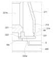
내부 케이스(210)는 경사부(211), 수직부(212), 지지부(213) 및 토출구(214)를 포함한다.The
경사부(211)는 외부 케이스(220)의 안쪽을 향하는 방향으로 일정 각도로 경사진 형태를 갖는다. 이에 따라, 내부 케이스(210)의 상부는 하부보다 큰 직경을 갖는다.The
본 발명의 일 실시예에 따르면, 경사부(211)는 외부 케이스(220)와 후술할 흡기구(231)의 폭보다 큰 거리로 이격될 수 있다.According to one embodiment of the present invention, the
수직부(212)는 외부 케이스(220)와 이격되어 배치되고, 경사부(211)의 하부로부터 후술할 하부 플레이트(222)를 향하여 수직으로 연장된다. 수직부(212)는 하부 플레이트(222)의 돌출부(222a)와 이격되어 배치된다.The
도시되지 않았지만, 수직부(212)는 평면상에서 레이저 가공 처리되는 기판의 커팅 라인과 대응하는 형태로 배치될 수 있다. 예를 들어, 피처리 기판의 커팅 라인이 평면상에서 사각형인 경우, 수직부(212)는 평면상 사각형 형상의 공간을 정의하도록 배치될 수 있다.Although not shown, the
내부 케이스(210)의 지지부(213)는 경사부(211)의 상부로부터 수평 방향으로 연장된다. 후술할 외부 케이스(220)의 지지부(221a) 상에 내부 케이스(210)의 지지부(213)가 배치되고, 내부 케이스(210)의 지지부(213) 상에 분사 유닛(100)이 배치된다.The
토출구(214)는 수직부(212)에 의해 정의되는 내부 공간으로, 분진 및 분사 유닛(100)으로부터 분사된 공기의 유동 경로를 형성한다. 토출구(214)는 레이저 가공에 의해 커팅되는 피처리 기판(S)의 커팅 라인에 대응하는 형태를 가질 수 있다. 구체적으로, 수직부(212)가 피처리 기판(S)의 커팅 라인에 대응하여 배치되기 때문에, 수직부(212)에 의해 정의되는 토출구(214)는 피처리 기판(S)의 커팅 라인과 실질적으로 동일한 형태를 가질 수 있다. 이에 따라, 피처리 기판(S)의 커팅 공정 중 본 발명에 따른 분진 제거 장치를 이동시키지 않고 분진을 제거하기 때문에, 분진이 외부로 유출되는 것을 방지할 수 있다. 또한, 토출구(214)의 폭(Wd)은 피처리 기판(S)의 커팅 라인의 크기에 비례할 수 있다.The
외부 케이스(220)는 측벽부(221) 및 하부 플레이트(222)를 포함한다.The
측벽부(221)는 내부 케이스(210)를 둘러싸도록 배치되고, 측벽부(221)의 적어도 일부는 내부 케이스(210)와 이격되어 공기의 유동 경로를 형성한다.The
도 3에 도시된 바와 같이, 측벽부(221)는 지지부(221a) 및 배기구(221b)를 포함한다.As shown in FIG. 3 , the
외부 케이스(220)의 지지부(221a)는 분사 유닛(100) 및 내부 케이스(210)를 지지한다. 구체적으로, 외부 케이스(220)의 지지부(221a) 상에 내부 케이스(210)의 지지부(213) 및 분사 유닛(100)이 위치한다. 이때, 외부 케이스(220)의 지지부(221a)는 내부 케이스(210)의 지지부(213) 및 분사 유닛(110)과 나사와 같은 결합 부재에 의해 결합될 수 있다.The
배기구(221b)는 지지부(221a)에 의해 정의된다. 배기구(221b)는 외부 케이스(220)의 적어도 한 측벽부(221)에 위치한다. 배기구(221b)는 배기관(310)을 통해 흡입 펌프(미도시)와 연결되어 분진 및 공기의 유동 경로를 형성한다. The
하부 플레이트(222)는 측벽부(221)를 지지한다. 즉, 하부 플레이트(222) 상에 측벽부(221)가 위치한다.The
하부 플레이트(222)는 돌출부(222a)를 포함한다.The
돌출부(222a)는 측벽부(221)로부터 외부 케이스(220)의 내부를 향하여 돌출된다. 이에 따라, 하부 플레이트(222)는 내부 케이스(210)와 함께 분진 및 공기가 배출될 수 있는 공간을 정의한다. 구체적으로, 하부 플레이트(222)의 돌출부(222a)는 내부 케이스(210)의 수직부(212)와 함께 흡기구(231)를 정의한다. 예를 들어, 돌출부(222a)의 끝단은 수직부(212) 하부의 끝단과 함께 흡기구(231)를 정의한다. 이때, 본 발명의 일 실시예에 따르면, 돌출부(222a)는 내부 케이스(210)의 수직부(212)와 평면상에서 중첩할 수 있다. 구체적으로, 돌출부(222a)의 끝단은 수직부(212) 하단의 끝단과 평면상에서 중첩할 수 있다.The protruding
도시되지 않았지만, 흡기구(231)는 수직부(212)의 단면에 대응하는 형상을 가질 수 있다.Although not shown, the
흡기구(231)는 20mm 이하의 폭(Wi)을 가질 수 있다. 이때, 흡기구(231)가 20mm 초과의 폭을 갖는 경우, 분진 및 공기의 유동 속도가 작아 분진이 외부로 유출될 수 있다. 예를 들어, 흡기구(231)는 5mm 이상 10mm 이하의 폭(Wi)을 가질 수 있다.The
흡기구(231)는 내부 케이스(210)의 수직부(212)에 의해 정의된 토출구(214)의 내경(Wd)보다 작은 폭(Wi)을 갖는다.The
돌출부(222a)는 내부 케이스(210)에서 외부 케이스(220)로 이동하는 공기의 유출을 방지한다. 구체적으로, 돌출부(222a)는 내부 케이스(210) 및 외부 케이스(220)와 함께, 배기구(221b)로 향하는 공기의 유동 경로를 형성하여, 내부 케이스(210)에서 외부 케이스(220)로 이동하는 공기가 외부로 유출되는 것을 방지한다.The
하부 플레이트(222)는 측벽부(221)와 일체일 수 있다. 구체적으로, 돌출부(222a)는 측벽부(221)와 일체로 형성될 수 있다. 또는, 하부 플레이트(222)는 측벽부(221)와 별도의 구성요소로 나사와 같은 결합 부재를 통해 결합될 수 있다.The
흡입 유닛은, 도 1 및 도 2에 도시된 바와 같이, 배기관(310) 및 배기관(310)과 연결된 흡입 펌프(미도시)를 포함할 수 있다.As shown in FIGS. 1 and 2 , the suction unit may include an
배기관(310)은 외부 케이스(220)와 흡입 펌프를 서로 연결하여 배기구(221b)에서 흡입 펌프로 향하는 분진 및 공기 유동 경로를 형성한다.The
흡입 펌프는 내부 케이스(210) 및 외부 케이스(220) 내의 공기 및 분진을 흡입하는 동력을 제공한다. 이에 따라, 흡입 펌프는 토출구(214)에서 흡기구(231)를 통해 배기구(221b)로 향하는 분진 및 공기의 유동 경로를 형성한다.The suction pump provides power to suck air and dust in the
스테이지(400)는 레이저 가공 처리되는 피처리 기판(S)이 안착되는 공간을 제공한다. 스테이지(400)는 하부 플레이트(222)의 돌출부(222a)와 이격되어 배치될 수 있다.The
도 4는 도 3의 ‘A’ 부분을 확대한 확대도이다.FIG. 4 is an enlarged view of part ‘A’ of FIG. 3 .
본 발명의 일 실시예에 따르면, 스테이지(400)는 하부 플레이트(222)의 돌출부(222a)와 20mm 이하의 간격(Ws)으로 이격될 수 있다. 스테이지(400)가 20mm 초과의 거리로 이격된 경우, 피처리 기판(S)에서 발생한 분진이 분진 제거 장치 외부로 유출될 수 있다. 예를 들어, 스테이지(400)는 하부 플레이트(222)의 돌출부(222a)와 3mm 이상 10mm 이하 이격(Ws)될 수 있다.According to one embodiment of the present invention, the
도 3 및 도 4를 참조하여, 본 발명의 일 실시예에 따른 분진 제거 장치에 의해 분진이 제거되는 과정을 상세히 설명한다.Referring to Figures 3 and 4, a process of removing dust by the dust removal device according to an embodiment of the present invention will be described in detail.
도 3을 참조하면, 스테이지(320) 상에 배치된 피처리 기판(S)이 레이저 조사부(미도시)로부터 출사된 레이저 광에 의해 가공된다. 구체적으로, 레이저 조사부로부터 출사된 레이저 광은 본 발명의 일 실시예에 따른 분진 제거 장치를 통과하여 피처리 기판(S)을 가공한다. 이때, 가공되는 피처리 기판(S)에서 분진이 발생한다.Referring to FIG. 3 , the target substrate S disposed on the stage 320 is processed by laser light emitted from a laser irradiation unit (not shown). Specifically, the laser light emitted from the laser irradiator passes through the dust removal device according to an embodiment of the present invention to process the target substrate (S). At this time, dust is generated from the substrate S to be processed.
분사 유닛(100)은 내부 케이스(210)의 하부를 향해 공기를 분사하여 피처리 기판(S)에서 발생한 분진이 내부 케이스(210)의 상부 방향으로 이동 및 유출되지 않도록 한다. 분사 유닛(100)에 의해 분사된 공기는 내부 케이스(210)의 경사부(211)를 따라 이동된다.The
내부 케이스(210)의 경사부(211)를 따라 이동된 공기는 분사 유닛(100)에서분사된 공기 압력에 의해 토출구(214)로 이동한다.The air moved along the
토출구(214)를 통과한 공기는 흡기구(231)로 이동한다. 이때, 흡기구(231)는토출구(214)의 내경(Wd)보다 작은 폭(Wi)을 갖기 때문에, 흡기구(231)를 통해 공기 및 분진의 유동 경로가 형성된다.The air passing through the
흡기구(231)는 토출구(214)의 내경(Wd)보다 작은 폭(Wi)을 갖기 때문에, 토출구(214)보다 작은 단면적을 갖는다. 이때, 유체의 속력은 유체가 통과하는 단면적에 반비례한다는 베르누이의 원리에 의해, 흡기구(231)에서 공기의 속도는 토출구(214)에서 공기의 속도보다 크다. 즉, 토출구(214)를 통과한 공기는 흡기구(231)에서 이동 속도가 증가한다. 따라서, 피처리 기판(S)에서 발생한 분진은 이동 속도가 증가된 공기와 함께 흡기구(231)를 통해 고속으로 이동한다.Since the
본 발명의 일 실시예에 따르면, 흡기구(231)는 20mm 이하의 폭(Wi)을 가질 수 있다.According to one embodiment of the present invention, the
흡기구(231)를 통해 이동된 분진 및 공기는 내부 케이스(210)와 외부 케이스(220) 사이에 형성된 공간을 통해 배기구(221b)로 이동될 수 있다. 이때, 내부 케이스(210)의 경사부(211)와 외부 케이스(220) 사이의 이격 거리는 흡기구(231)의 폭보다 클 수 있다. 이에 따라, 흡기구(231)는 분진 및 공기 유동 경로 중 가장 작은 단면적을 갖기 때문에, 공기는 흡기구(231)에서 가장 빠른 속도로 이동될 수 있다.Dust and air moved through the
또한, 흡입 펌프에 의해 형성된 흡입력은 피처리 기판(S)과 외부 케이스(220) 사이의 이격된 공간에서 외부 케이스(220) 내부로 향하는 공기 유동 경로를 형성한다. 이에 따라, 피처리 기판(S)과 외부 케이스(220) 사이의 이격된 공간을 통해 분진이 외부 케이스(220)의 외부로 유출되는 것을 방지할 수 있다.In addition, the suction force generated by the suction pump forms an air flow path toward the inside of the
본 발명의 일 실시예에 따르면, 피처리 기판(S)의 레이저 커팅 공정 중 발생하는 분진은 외부에 유출되지 않고 효과적으로 제거될 수 있다. 따라서, 분진에 의한 표시 패널 및 생산 설비 내부 부품의 오염을 방지할 수 있다.According to an embodiment of the present invention, dust generated during the laser cutting process of the substrate S to be processed can be effectively removed without leaking to the outside. Accordingly, it is possible to prevent contamination of the display panel and internal parts of the production facility by dust.
흡기구(231)를 통과한 분진 및 공기는 배기구(221b) 및 배기관(310)를 통해 분진 제거 장치의 외부로 배출된다.The dust and air passing through the
도 5는 도 3의 ‘A’부분을 확대한 다른 확대도이다. 이하, 본 발명의 다른 실시예에 따른 분진 제거 장치 및 이를 포함하는 레이저 커팅 장치의 구조에 대해 상세히 설명한다.FIG. 5 is another enlarged view in which part 'A' of FIG. 3 is enlarged. Hereinafter, the structure of a dust removal device and a laser cutting device including the same according to another embodiment of the present invention will be described in detail.
본 발명의 다른 일 실시예에 따른 분진 제거 장치 및 이를 포함하는 레이저 커팅 장치에 관한 설명과 중복되는 내용은 생략한다.Descriptions of the dust removal device and the laser cutting device including the same according to another embodiment of the present invention and overlapping descriptions will be omitted.
외부 케이스(220)는 측벽부(221) 및 하부 플레이트(222)를 포함한다.The
측벽부(221)는 내부 케이스(210)와 이격되어 내부 케이스(210)를 둘러싸도록 배치된다.The
하부 플레이트(222)는 돌출부(222a)를 포함한다.The
돌출부(222a)는 측벽부(221)로부터 외부 케이스(220)의 내부를 향하여 돌출된다. 이에 따라, 하부 플레이트(222)는 내부 케이스(210)와 함께 분진 및 공기가 배출될 수 있는 공간을 정의한다. 구체적으로, 하부 플레이트(222)의 돌출부(222a)는 내부 케이스(210)의 수직부(212)와 함께 흡기구(231)를 정의한다. 예를 들어, 돌출부(222a)의 끝단은 수직부(212) 하부의 끝단과 함께 흡기구(231)를 정의한다. 이때, 본 발명의 다른 일 실시예에 따르면, 돌출부(222a)는 내부 케이스(210)의 수직부(212)와 평면상에서 중첩하지 않을 수 있다. 구체적으로, 돌출부(222a)의 끝단은 수직부(212) 하단의 끝단과 평면상에서 중첩하지 않을 수 있다.The protruding
도시되지 않았지만, 흡기구(231)는 평면상에서 폐곡선 형상을 가질 수 있다. 구체적으로, 본 발명의 다른 일 실시예에 따르면, 흡기구(231)는 평면상에서 토출구(214)를 둘러싸는 링 형상일 수 있다.Although not shown, the
흡기구(231)는 20mm 이하의 폭(Wi)을 가질 수 있다. 이때, 흡기구(231)가 20mm 초과의 폭을 갖는 경우, 분진 및 공기의 유동 속도가 작아 분진이 외부로 유출될 수 있다.The
흡기구(231)는 내부 케이스(210)의 수직부(212)에 의해 정의된 토출구(214)의 내경(Wd)보다 작은 폭(Ws)을 갖는다.The
본 발명의 다른 일 실시예에 따르면, 피처리 기판(S)의 레이저 커팅 공정 중 발생하는 분진을 외부에 유출시키지 않고 효과적으로 제거할 수 있다. 따라서, 분진에 의한 표시 패널 및 생산 설비 내부 부품의 오염을 방지할 수 있다.According to another embodiment of the present invention, dust generated during the laser cutting process of the substrate S to be processed can be effectively removed without leaking to the outside. Accordingly, it is possible to prevent contamination of the display panel and internal parts of the production facility by dust.
이상에서 설명한 본 발명은 상술한 실시예 및 첨부된 도면에 한정되는 것이 아니고, 본 발명의 기술적 사상을 벗어나지 않는 범위 내에서 여러 가지 치환, 변형 및 변경이 가능하다는 것이 본 발명이 속하는 기술 분야에서 통상의 지식을 가진 자에게 있어 명백할 것이다.The present invention described above is not limited to the above-described embodiments and the accompanying drawings, and it is common in the technical field to which the present invention belongs that various substitutions, modifications, and changes are possible within a range that does not deviate from the technical spirit of the present invention. It will be clear to those who have knowledge of
100: 분사 유닛210: 내부 케이스
211: 경사부212: 수직부
213: 지지부214: 토출구
220: 외부 케이스221: 측벽부
221a: 지지부221b: 배기구
222: 하부 플레이트222a: 돌출부
231: 흡기구310: 배기관
400: 스테이지100: injection unit 210: inner case
211: inclined portion 212: vertical portion
213: support 214: discharge port
220: outer case 221: side wall portion
221a:
222:
231: intake port 310: exhaust pipe
400: stage
Claims (20)
Translated fromKorean상기 스테이지 상에 배치되고 토출구를 정의하는 내부 케이스;
상기 내부 케이스의 외면을 둘러싸도록 배치된 측벽부 및 상기 측벽부의 하부 끝단으로부터 돌출된 돌출부를 포함하고, 상기 측벽부에 위치한 배기구를 갖는 외부 케이스;
상기 배기구에서 공기를 흡입하는 동력을 제공하는 흡입 펌프;
상기 내부 케이스 상에 배치되고, 상기 내부 케이스 내부로 공기를 분사하는 분사 유닛; 및
상기 외부 케이스의 돌출부의 끝단 및 상기 내부 케이스의 하부 끝단에 의해 정의되는 흡기구;를 포함하고,
상기 흡기구는 상기 토출구보다 작은 폭을 갖는 분진 제거 장치.stage;
an inner case disposed on the stage and defining a discharge port;
an outer case including a side wall portion disposed to surround an outer surface of the inner case and a protrusion protruding from a lower end of the side wall portion, and having an exhaust port located on the side wall portion;
a suction pump providing power to suck air from the exhaust port;
a spraying unit disposed on the inner case and spraying air into the inner case; and
Including; intake port defined by the end of the protrusion of the outer case and the lower end of the inner case,
The dust removal device of claim 1, wherein the intake port has a smaller width than the discharge port.
상기 외부 케이스의 돌출부는 상기 스테이지로부터 20mm 이하 거리만큼 이격된 분진 제거 장치.According to claim 1,
The protrusion of the outer case is spaced apart from the stage by a distance of 20 mm or less.
상기 내부 케이스는
일정 각도로 경사진 형태인 경사부;
상기 경사부의 하부로부터 수직으로 연장된 수직부;및
상기 수직부에 의해 정의되는 토출구;를 포함하는 분진 제거 장치.According to claim 1,
the inner case
an inclined portion inclined at a certain angle;
A vertical portion extending vertically from the bottom of the inclined portion; and
Dust removal device comprising a; discharge port defined by the vertical portion.
상기 경사부와 상기 외부 케이스 사이의 이격 거리는 상기 흡기구의 폭보다 큰 분진 제거 장치.According to claim 3,
The separation distance between the inclined portion and the outer case is greater than the width of the inlet.
상기 흡기구는 상기 돌출부의 끝단 및 상기 수직부의 하부 끝단에 의해 정의되는 분진 제거 장치.According to claim 3,
The dust removal device of claim 1, wherein the inlet is defined by an end of the protruding portion and a lower end of the vertical portion.
상기 흡기구는 20mm 이하의 폭을 갖는 분진 제거 장치.According to claim 3,
The dust removal device having a width of 20 mm or less.
상기 돌출부의 적어도 일부는 평면상에서 상기 경사부 및 상기 수직부와 중첩하는 분진 제거 장치.According to claim 3,
At least a portion of the protruding portion overlaps the inclined portion and the vertical portion on a plane.
상기 돌출부의 끝단은 평면상에서 상기 수직부와 중첩하는 분진 제거 장치.According to claim 3,
An end of the protruding portion overlaps the vertical portion on a plane.
상기 돌출부의 적어도 일부는 평면상에서 상기 경사부와 중첩하고, 상기 수직부와 중첩하지 않는 분진 제거 장치.According to claim 3,
At least a portion of the protruding portion overlaps the inclined portion on a plane and does not overlap the vertical portion.
상기 돌출부의 끝단은 평면상에서 상기 수직부와 중첩하지 않는 분진 제거 장치.According to claim 3,
An end of the protruding portion does not overlap the vertical portion on a plane.
상기 흡기구는 평면상에서 폐곡선 형상을 갖는 분진 제거 장치.According to claim 3,
The inlet is a dust removal device having a closed curve shape on a plane.
상기 분사 유닛은,
유입관;
상기 유입관과 연결된 유출관;및
상기 유출관과 연결된 분사 노즐;을 포함하는 분진 제거 장치.According to claim 1,
The injection unit is
inlet pipe;
an outlet pipe connected to the inlet pipe; and
Dust removal device comprising a; injection nozzle connected to the outlet pipe.
상기 분사 노즐의 분사 각도를 조절하는 각도 조절부를 포함하는 분진 제거 장치.According to claim 12,
Dust removal device comprising an angle adjusting unit for adjusting the spray angle of the spray nozzle.
상기 스테이지 상에 이격되어 배치된 분진 제거 장치; 및
상기 분진 제거 장치 상에 이격되어 배치되고, 상기 분진 제거 장치에 의해 정의된 내부의 공간을 통해 레이저 광을 조사하는 레이저 조사부; 를 포함하고,
상기 분진 제거 장치는,
상기 스테이지 상에 배치되고 토출구를 정의하는 내부 케이스;
상기 내부 케이스의 외면을 둘러싸도록 배치된 측벽부 및 상기 측벽부의 하부 끝단으로부터 돌출된 돌출부를 포함하고, 상기 측벽부에 위치한 배기구를 갖는 외부 케이스;
배기관을 통해 상기 배기구와 연결된 흡입 펌프;
상기 내부 케이스 상에 배치되고, 상기 내부 케이스 내부로 공기를 분사하는 분사 유닛; 및
상기 외부 케이스의 돌출부의 끝단 및 상기 내부 케이스의 하부 끝단에 의해 정의되는 흡기구;를 포함하고,
상기 흡기구는 상기 토출구보다 작은 폭을 갖는 레이저 커팅 장치.stage;
dust removal devices spaced apart from each other on the stage; and
a laser irradiation unit that is spaced apart from the dust removal device and irradiates laser light through an inner space defined by the dust removal device; including,
The dust removal device,
an inner case disposed on the stage and defining a discharge port;
an outer case including a side wall portion disposed to surround an outer surface of the inner case and a protrusion protruding from a lower end of the side wall portion, and having an exhaust port located on the side wall portion;
a suction pump connected to the exhaust port through an exhaust pipe;
a spraying unit disposed on the inner case and spraying air into the inner case; and
Including; intake port defined by the end of the protrusion of the outer case and the lower end of the inner case,
The laser cutting device wherein the intake port has a smaller width than the discharge port.
상기 외부 케이스의 돌출부는 상기 스테이지로부터 20mm 이하 거리만큼 이격된 레이저 커팅 장치.According to claim 14,
The laser cutting device of the protrusion of the outer case is spaced apart from the stage by a distance of 20 mm or less.
상기 내부 케이스는
일정 각도로 경사진 형태인 경사부;
상기 경사부의 하부로부터 연장된 수직부;및
상기 수직부에 의해 정의되는 토출구;를 포함하는 레이저 컷팅 장치.According to claim 14,
the inner case
an inclined portion inclined at a certain angle;
A vertical portion extending from the bottom of the inclined portion; and
Laser cutting device comprising a; discharge port defined by the vertical portion.
상기 경사부와 상기 외부 케이스 사이의 이격거리는 상기 흡기구의 폭보다 큰 분진 제거 장치.According to claim 16,
The separation distance between the inclined portion and the outer case is greater than the width of the inlet.
상기 흡기구는 상기 돌출부의 끝단 및 상기 수직부의 하부 끝단에 의해 정의되는 레이저 커팅 장치.According to claim 16,
The inlet is a laser cutting device defined by an end of the protrusion and a lower end of the vertical part.
상기 흡기구는 20mm 이하의 폭을 갖는 레이저 커팅 장치.According to claim 18,
The inlet is a laser cutting device having a width of 20 mm or less.
상기 흡기구는 폐곡선 형상을 갖는 레이저 커팅 장치.According to claim 14,
The inlet is a laser cutting device having a closed curve shape.
Priority Applications (2)
| Application Number | Priority Date | Filing Date | Title |
|---|---|---|---|
| KR1020180018183AKR102532733B1 (en) | 2018-02-14 | 2018-02-14 | Particle removal apparatus and laser cutting apparatus including the same |
| US16/191,575US11351632B2 (en) | 2018-02-14 | 2018-11-15 | Particle removal apparatus and laser cutting apparatus including the same |
Applications Claiming Priority (1)
| Application Number | Priority Date | Filing Date | Title |
|---|---|---|---|
| KR1020180018183AKR102532733B1 (en) | 2018-02-14 | 2018-02-14 | Particle removal apparatus and laser cutting apparatus including the same |
Publications (2)
| Publication Number | Publication Date |
|---|---|
| KR20190098875A KR20190098875A (en) | 2019-08-23 |
| KR102532733B1true KR102532733B1 (en) | 2023-05-16 |
Family
ID=67541984
Family Applications (1)
| Application Number | Title | Priority Date | Filing Date |
|---|---|---|---|
| KR1020180018183AActiveKR102532733B1 (en) | 2018-02-14 | 2018-02-14 | Particle removal apparatus and laser cutting apparatus including the same |
Country Status (2)
| Country | Link |
|---|---|
| US (1) | US11351632B2 (en) |
| KR (1) | KR102532733B1 (en) |
Families Citing this family (9)
| Publication number | Priority date | Publication date | Assignee | Title |
|---|---|---|---|---|
| JP6998177B2 (en)* | 2017-11-02 | 2022-01-18 | 株式会社ディスコ | Laser processing equipment |
| KR102543915B1 (en) | 2018-04-09 | 2023-06-16 | 삼성디스플레이 주식회사 | Substrate processing apparatus and substrate processing method |
| JP7426257B2 (en) | 2020-02-27 | 2024-02-01 | 本田技研工業株式会社 | laser processing equipment |
| JP7402081B2 (en)* | 2020-02-27 | 2023-12-20 | 本田技研工業株式会社 | laser processing equipment |
| KR102836825B1 (en)* | 2020-04-22 | 2025-07-22 | 삼성디스플레이 주식회사 | Apparatus for manufacturing display device and method for manufacturing display device |
| KR102175158B1 (en) | 2020-08-24 | 2020-11-05 | ㈜ 엘에이티 | Fume and Dust Exhaust Device for Laser Cutting |
| KR102182608B1 (en) | 2020-08-24 | 2020-11-24 | ㈜ 엘에이티 | Laser Cutting System |
| CN113042466B (en)* | 2021-05-14 | 2022-03-04 | 圣同激光设备(上海)有限公司 | Portable laser cleaning machine and cleaning method |
| KR102422000B1 (en)* | 2021-07-20 | 2022-07-19 | 진명기술주식회사 | Apparatus for process processing using laser |
Family Cites Families (29)
| Publication number | Priority date | Publication date | Assignee | Title |
|---|---|---|---|---|
| FR2627409A1 (en)* | 1988-02-24 | 1989-08-25 | Lectra Systemes Sa | LASER CUTTING APPARATUS WITH A FUME EXHAUST DEVICE |
| US5254834A (en)* | 1992-06-02 | 1993-10-19 | Johnstech International Corporation | Method of forming closely-spaced, generally parallel slots through a thin wall and product formed thereby |
| JPH09271979A (en)* | 1996-04-09 | 1997-10-21 | Nec Corp | Local vacuum laser beam welding machine |
| JPH09281296A (en)* | 1996-04-10 | 1997-10-31 | Ishikawajima Harima Heavy Ind Co Ltd | Laser decontamination equipment |
| JP3498895B2 (en)* | 1997-09-25 | 2004-02-23 | シャープ株式会社 | Substrate cutting method and display panel manufacturing method |
| AT408632B (en)* | 1998-01-29 | 2002-01-25 | Trodat Gmbh | MACHINING HEAD FOR A LASER ENGRAVING OR cutting apparatus |
| KR19990074461A (en)* | 1998-03-11 | 1999-10-05 | 윤종용 | Contaminant Removal Device for Semiconductor Wafer Polishing Equipment |
| GB2342883A (en)* | 1998-10-23 | 2000-04-26 | Rolls Royce Plc | Improvements in or relating to laser machining of articles |
| JP2001150177A (en)* | 1999-11-29 | 2001-06-05 | Nippon Sharyo Seizo Kaisha Ltd | Shield gas atmosphere keeping device for laser beam machine |
| US7863542B2 (en)* | 2005-12-22 | 2011-01-04 | Sony Corporation | Laser processing apparatus and laser processing method as well as debris extraction mechanism and debris extraction method |
| US7450213B2 (en)* | 2006-06-29 | 2008-11-11 | Lg Display Co., Ltd. | Methods of manufacturing liquid crystal display devices |
| JP4404085B2 (en)* | 2006-11-02 | 2010-01-27 | ソニー株式会社 | Laser processing apparatus, laser processing head, and laser processing method |
| EP2139637B1 (en)* | 2007-03-21 | 2015-09-23 | Flowserve Management Company | Laser surface treatment for mechanical seal faces |
| US8207472B2 (en)* | 2008-06-18 | 2012-06-26 | Electro Scientific Industries, Inc. | Debris capture and removal for laser micromachining |
| US8312994B2 (en)* | 2009-03-18 | 2012-11-20 | Pelletron Corporation | Cylindrical dedusting apparatus for particulate material |
| KR20110062886A (en) | 2009-12-04 | 2011-06-10 | 티에스씨멤시스(주) | Particle removal device of laser processing equipment and laser processing equipment equipped with the same |
| JP2012030249A (en) | 2010-07-29 | 2012-02-16 | Hitachi High-Technologies Corp | Dust collector, laser beam machining device using the same and method of manufacturing solar panel |
| JP2013045877A (en)* | 2011-08-24 | 2013-03-04 | Tokyo Electron Ltd | Substrate processing apparatus |
| KR20130091849A (en) | 2012-02-09 | 2013-08-20 | 주식회사 엘티에스 | Apparatus for removing particles in laser head |
| KR101960745B1 (en)* | 2012-11-14 | 2019-03-21 | 엘지디스플레이 주식회사 | Method of cutting flexible display device and method of fabricating flexible display device |
| KR101485062B1 (en) | 2013-10-29 | 2015-01-22 | 주식회사 에이에스티젯텍 | Removable suction nozzle device of laser processing devices |
| JP6788571B2 (en)* | 2014-07-14 | 2020-11-25 | コーニング インコーポレイテッド | Interface blocks, systems and methods for cutting transparent substrates within a wavelength range using such interface blocks. |
| KR101552562B1 (en) | 2014-09-18 | 2015-09-15 | 주식회사 필옵틱스 | Particle suction apparatus and laser processing system having the same |
| KR20160038634A (en) | 2014-09-30 | 2016-04-07 | 주식회사 이오테크닉스 | Dust prevention system and laser processing apparatus having the dust prevention system |
| KR20160051470A (en) | 2014-11-03 | 2016-05-11 | 주식회사 이오테크닉스 | Fume Removal Equipment |
| DE102015118486B4 (en)* | 2015-10-29 | 2020-03-26 | Fraunhofer-Gesellschaft zur Förderung der angewandten Forschung e.V. | Method and device for laser welding in a gas atmosphere |
| WO2018039394A1 (en)* | 2016-08-25 | 2018-03-01 | Corning Incorporated | Method and apparatus for cleaning a glass substrate |
| KR102744865B1 (en)* | 2016-12-01 | 2024-12-23 | 삼성디스플레이 주식회사 | Display device and method of manufacturing the same |
| US11253884B2 (en)* | 2016-12-09 | 2022-02-22 | Circle Dynamics, Inc. | Device for cleaning and drying a spraying unit |
- 2018
- 2018-02-14KRKR1020180018183Apatent/KR102532733B1/enactiveActive
- 2018-11-15USUS16/191,575patent/US11351632B2/enactiveActive
Also Published As
| Publication number | Publication date |
|---|---|
| KR20190098875A (en) | 2019-08-23 |
| US11351632B2 (en) | 2022-06-07 |
| US20190247954A1 (en) | 2019-08-15 |
Similar Documents
| Publication | Publication Date | Title |
|---|---|---|
| KR102532733B1 (en) | Particle removal apparatus and laser cutting apparatus including the same | |
| KR20210054558A (en) | Substrate processing apparatus and substrate processing method | |
| US11565351B2 (en) | Substrate processing apparatus and substrate processing method | |
| US20150136185A1 (en) | Apparatus of cleaning substrate | |
| KR20190095625A (en) | Laser cutting device and suction unit | |
| KR102133967B1 (en) | Suction box for laser processing scanner head with air amplification and fume scattering prevention structure | |
| KR20240152000A (en) | Particle removal apparatus and laser cutting apparatus including the same | |
| KR101377997B1 (en) | Plasma etching apparatus and device for distributting gas | |
| US12048232B2 (en) | Apparatus for manufacturing display device with suction unit | |
| KR102824227B1 (en) | Laser cutting device, suction unit, and laser cutting method | |
| KR102824952B1 (en) | Laser machining device | |
| TWI568500B (en) | Apparatuses for jetting fluid | |
| KR101410038B1 (en) | Glass cutting apparatus | |
| KR102201882B1 (en) | Apparatus and method for treating substrate | |
| KR101856653B1 (en) | Module for using the pressure of air masses to fix the mask | |
| KR102198909B1 (en) | Apparatus for collecting non-product | |
| KR20220109580A (en) | Apparatus for Processing Substrate | |
| KR101398585B1 (en) | Plasma etching apparatus and baffle | |
| US20100162514A1 (en) | Apparatus for cleaning substrate | |
| US20160118241A1 (en) | Substrate treating apparatus and substrate cleaning method | |
| US20250098512A1 (en) | Suction unit, method of controlling the same and method of manufacturing display device using the same | |
| KR101377996B1 (en) | Plasma etching apparatus and mask device | |
| KR20140144370A (en) | Laser processing apparatus having a low temperature adsorption and laser processing method | |
| US9841594B2 (en) | Apparatus of coupling substrates for electrowetting display panel and method of coupling substrates for electrowetting display using the same | |
| KR20160072435A (en) | Substrate coater apparatus |
Legal Events
| Date | Code | Title | Description |
|---|---|---|---|
| PA0109 | Patent application | Patent event code:PA01091R01D Comment text:Patent Application Patent event date:20180214 | |
| PG1501 | Laying open of application | ||
| A201 | Request for examination | ||
| PA0201 | Request for examination | Patent event code:PA02012R01D Patent event date:20210119 Comment text:Request for Examination of Application Patent event code:PA02011R01I Patent event date:20180214 Comment text:Patent Application | |
| E902 | Notification of reason for refusal | ||
| PE0902 | Notice of grounds for rejection | Comment text:Notification of reason for refusal Patent event date:20220801 Patent event code:PE09021S01D | |
| E701 | Decision to grant or registration of patent right | ||
| PE0701 | Decision of registration | Patent event code:PE07011S01D Comment text:Decision to Grant Registration Patent event date:20230210 | |
| GRNT | Written decision to grant | ||
| PR0701 | Registration of establishment | Comment text:Registration of Establishment Patent event date:20230510 Patent event code:PR07011E01D | |
| PR1002 | Payment of registration fee | Payment date:20230511 End annual number:3 Start annual number:1 | |
| PG1601 | Publication of registration |