KR102532376B1 - A novel device for dispensing a multiphase mixture in a chamber containing a fluidizing medium - Google Patents
A novel device for dispensing a multiphase mixture in a chamber containing a fluidizing mediumDownload PDFInfo
- Publication number
- KR102532376B1 KR102532376B1KR1020197035165AKR20197035165AKR102532376B1KR 102532376 B1KR102532376 B1KR 102532376B1KR 1020197035165 AKR1020197035165 AKR 1020197035165AKR 20197035165 AKR20197035165 AKR 20197035165AKR 102532376 B1KR102532376 B1KR 102532376B1
- Authority
- KR
- South Korea
- Prior art keywords
- phase
- openings
- dispensing
- hard phase
- height
- Prior art date
- Legal status (The legal status is an assumption and is not a legal conclusion. Google has not performed a legal analysis and makes no representation as to the accuracy of the status listed.)
- Active
Links
- 239000000203mixtureSubstances0.000titledescription2
- 238000006243chemical reactionMethods0.000claimsabstractdescription22
- 239000003054catalystSubstances0.000claimsdescription16
- 238000000034methodMethods0.000claimsdescription15
- 239000007787solidSubstances0.000claimsdescription15
- 230000008929regenerationEffects0.000claimsdescription11
- 238000011069regeneration methodMethods0.000claimsdescription11
- 239000000725suspensionSubstances0.000claimsdescription8
- 239000002245particleSubstances0.000claimsdescription5
- 238000004523catalytic crackingMethods0.000claimsdescription4
- 229910052739hydrogenInorganic materials0.000claimsdescription4
- 239000003208petroleumSubstances0.000claimsdescription4
- 239000002028BiomassSubstances0.000claimsdescription3
- 239000001257hydrogenSubstances0.000claimsdescription3
- 239000004215Carbon black (E152)Substances0.000claimsdescription2
- UFHFLCQGNIYNRP-UHFFFAOYSA-NHydrogenChemical compound[H][H]UFHFLCQGNIYNRP-UHFFFAOYSA-N0.000claimsdescription2
- 229930195733hydrocarbonNatural products0.000claimsdescription2
- 150000002430hydrocarbonsChemical class0.000claimsdescription2
- 239000012071phaseSubstances0.000description44
- 239000012530fluidSubstances0.000description34
- 239000007789gasSubstances0.000description20
- 239000007788liquidSubstances0.000description12
- 239000007791liquid phaseSubstances0.000description6
- 238000005243fluidizationMethods0.000description3
- 238000004088simulationMethods0.000description3
- 239000007790solid phaseSubstances0.000description3
- 238000011144upstream manufacturingMethods0.000description3
- 238000005276aeratorMethods0.000description2
- 238000004517catalytic hydrocrackingMethods0.000description2
- 238000007233catalytic pyrolysisMethods0.000description2
- 238000002485combustion reactionMethods0.000description2
- 238000013461designMethods0.000description2
- 239000000839emulsionSubstances0.000description2
- 238000002156mixingMethods0.000description2
- 239000002002slurrySubstances0.000description2
- 238000012800visualizationMethods0.000description2
- 241000282326Felis catusSpecies0.000description1
- 238000009835boilingMethods0.000description1
- 238000003421catalytic decomposition reactionMethods0.000description1
- 230000000052comparative effectEffects0.000description1
- 238000005336crackingMethods0.000description1
- 239000006185dispersionSubstances0.000description1
- 238000004231fluid catalytic crackingMethods0.000description1
- 150000002431hydrogenChemical class0.000description1
- 230000002209hydrophobic effectEffects0.000description1
- 238000011835investigationMethods0.000description1
- 239000006194liquid suspensionSubstances0.000description1
- 230000002093peripheral effectEffects0.000description1
- 239000003209petroleum derivativeSubstances0.000description1
- 238000005381potential energyMethods0.000description1
- 230000001681protective effectEffects0.000description1
- 238000000926separation methodMethods0.000description1
- 238000012546transferMethods0.000description1
Images


Classifications
- B—PERFORMING OPERATIONS; TRANSPORTING
- B01—PHYSICAL OR CHEMICAL PROCESSES OR APPARATUS IN GENERAL
- B01J—CHEMICAL OR PHYSICAL PROCESSES, e.g. CATALYSIS OR COLLOID CHEMISTRY; THEIR RELEVANT APPARATUS
- B01J8/00—Chemical or physical processes in general, conducted in the presence of fluids and solid particles; Apparatus for such processes
- B01J8/18—Chemical or physical processes in general, conducted in the presence of fluids and solid particles; Apparatus for such processes with fluidised particles
- B01J8/1818—Feeding of the fluidising gas
- B01J8/1827—Feeding of the fluidising gas the fluidising gas being a reactant
- B—PERFORMING OPERATIONS; TRANSPORTING
- B01—PHYSICAL OR CHEMICAL PROCESSES OR APPARATUS IN GENERAL
- B01J—CHEMICAL OR PHYSICAL PROCESSES, e.g. CATALYSIS OR COLLOID CHEMISTRY; THEIR RELEVANT APPARATUS
- B01J8/00—Chemical or physical processes in general, conducted in the presence of fluids and solid particles; Apparatus for such processes
- B01J8/08—Chemical or physical processes in general, conducted in the presence of fluids and solid particles; Apparatus for such processes with moving particles
- B01J8/085—Feeding reactive fluids
- B—PERFORMING OPERATIONS; TRANSPORTING
- B01—PHYSICAL OR CHEMICAL PROCESSES OR APPARATUS IN GENERAL
- B01J—CHEMICAL OR PHYSICAL PROCESSES, e.g. CATALYSIS OR COLLOID CHEMISTRY; THEIR RELEVANT APPARATUS
- B01J8/00—Chemical or physical processes in general, conducted in the presence of fluids and solid particles; Apparatus for such processes
- B01J8/18—Chemical or physical processes in general, conducted in the presence of fluids and solid particles; Apparatus for such processes with fluidised particles
- B01J8/24—Chemical or physical processes in general, conducted in the presence of fluids and solid particles; Apparatus for such processes with fluidised particles according to "fluidised-bed" technique
- B01J8/26—Chemical or physical processes in general, conducted in the presence of fluids and solid particles; Apparatus for such processes with fluidised particles according to "fluidised-bed" technique with two or more fluidised beds, e.g. reactor and regeneration installations
- B—PERFORMING OPERATIONS; TRANSPORTING
- B01—PHYSICAL OR CHEMICAL PROCESSES OR APPARATUS IN GENERAL
- B01J—CHEMICAL OR PHYSICAL PROCESSES, e.g. CATALYSIS OR COLLOID CHEMISTRY; THEIR RELEVANT APPARATUS
- B01J8/00—Chemical or physical processes in general, conducted in the presence of fluids and solid particles; Apparatus for such processes
- B01J8/18—Chemical or physical processes in general, conducted in the presence of fluids and solid particles; Apparatus for such processes with fluidised particles
- B01J8/24—Chemical or physical processes in general, conducted in the presence of fluids and solid particles; Apparatus for such processes with fluidised particles according to "fluidised-bed" technique
- B01J8/44—Fluidisation grids
- C—CHEMISTRY; METALLURGY
- C10—PETROLEUM, GAS OR COKE INDUSTRIES; TECHNICAL GASES CONTAINING CARBON MONOXIDE; FUELS; LUBRICANTS; PEAT
- C10G—CRACKING HYDROCARBON OILS; PRODUCTION OF LIQUID HYDROCARBON MIXTURES, e.g. BY DESTRUCTIVE HYDROGENATION, OLIGOMERISATION, POLYMERISATION; RECOVERY OF HYDROCARBON OILS FROM OIL-SHALE, OIL-SAND, OR GASES; REFINING MIXTURES MAINLY CONSISTING OF HYDROCARBONS; REFORMING OF NAPHTHA; MINERAL WAXES
- C10G47/00—Cracking of hydrocarbon oils, in the presence of hydrogen or hydrogen- generating compounds, to obtain lower boiling fractions
- C10G47/24—Cracking of hydrocarbon oils, in the presence of hydrogen or hydrogen- generating compounds, to obtain lower boiling fractions with moving solid particles
- C10G47/30—Cracking of hydrocarbon oils, in the presence of hydrogen or hydrogen- generating compounds, to obtain lower boiling fractions with moving solid particles according to the "fluidised-bed" technique
- B—PERFORMING OPERATIONS; TRANSPORTING
- B01—PHYSICAL OR CHEMICAL PROCESSES OR APPARATUS IN GENERAL
- B01J—CHEMICAL OR PHYSICAL PROCESSES, e.g. CATALYSIS OR COLLOID CHEMISTRY; THEIR RELEVANT APPARATUS
- B01J2208/00—Processes carried out in the presence of solid particles; Reactors therefor
- B01J2208/00796—Details of the reactor or of the particulate material
- B01J2208/00893—Feeding means for the reactants
- B01J2208/00902—Nozzle-type feeding elements
- B—PERFORMING OPERATIONS; TRANSPORTING
- B01—PHYSICAL OR CHEMICAL PROCESSES OR APPARATUS IN GENERAL
- B01J—CHEMICAL OR PHYSICAL PROCESSES, e.g. CATALYSIS OR COLLOID CHEMISTRY; THEIR RELEVANT APPARATUS
- B01J2208/00—Processes carried out in the presence of solid particles; Reactors therefor
- B01J2208/00796—Details of the reactor or of the particulate material
- B01J2208/00893—Feeding means for the reactants
- B01J2208/0092—Perforated plates
- B—PERFORMING OPERATIONS; TRANSPORTING
- B01—PHYSICAL OR CHEMICAL PROCESSES OR APPARATUS IN GENERAL
- B01J—CHEMICAL OR PHYSICAL PROCESSES, e.g. CATALYSIS OR COLLOID CHEMISTRY; THEIR RELEVANT APPARATUS
- B01J2208/00—Processes carried out in the presence of solid particles; Reactors therefor
- B01J2208/00796—Details of the reactor or of the particulate material
- B01J2208/00893—Feeding means for the reactants
- B01J2208/00929—Provided with baffles
- B—PERFORMING OPERATIONS; TRANSPORTING
- B01—PHYSICAL OR CHEMICAL PROCESSES OR APPARATUS IN GENERAL
- B01J—CHEMICAL OR PHYSICAL PROCESSES, e.g. CATALYSIS OR COLLOID CHEMISTRY; THEIR RELEVANT APPARATUS
- B01J2208/00—Processes carried out in the presence of solid particles; Reactors therefor
- B01J2208/00796—Details of the reactor or of the particulate material
- B01J2208/00938—Flow distribution elements
- B—PERFORMING OPERATIONS; TRANSPORTING
- B01—PHYSICAL OR CHEMICAL PROCESSES OR APPARATUS IN GENERAL
- B01J—CHEMICAL OR PHYSICAL PROCESSES, e.g. CATALYSIS OR COLLOID CHEMISTRY; THEIR RELEVANT APPARATUS
- B01J4/00—Feed or outlet devices; Feed or outlet control devices
- B01J4/001—Feed or outlet devices as such, e.g. feeding tubes
- B01J4/002—Nozzle-type elements
- B—PERFORMING OPERATIONS; TRANSPORTING
- B01—PHYSICAL OR CHEMICAL PROCESSES OR APPARATUS IN GENERAL
- B01J—CHEMICAL OR PHYSICAL PROCESSES, e.g. CATALYSIS OR COLLOID CHEMISTRY; THEIR RELEVANT APPARATUS
- B01J8/00—Chemical or physical processes in general, conducted in the presence of fluids and solid particles; Apparatus for such processes
- B01J8/0015—Feeding of the particles in the reactor; Evacuation of the particles out of the reactor
- B01J8/004—Feeding of the particles in the reactor; Evacuation of the particles out of the reactor by means of a nozzle
- Y—GENERAL TAGGING OF NEW TECHNOLOGICAL DEVELOPMENTS; GENERAL TAGGING OF CROSS-SECTIONAL TECHNOLOGIES SPANNING OVER SEVERAL SECTIONS OF THE IPC; TECHNICAL SUBJECTS COVERED BY FORMER USPC CROSS-REFERENCE ART COLLECTIONS [XRACs] AND DIGESTS
- Y02—TECHNOLOGIES OR APPLICATIONS FOR MITIGATION OR ADAPTATION AGAINST CLIMATE CHANGE
- Y02P—CLIMATE CHANGE MITIGATION TECHNOLOGIES IN THE PRODUCTION OR PROCESSING OF GOODS
- Y02P30/00—Technologies relating to oil refining and petrochemical industry
- Y02P30/20—Technologies relating to oil refining and petrochemical industry using bio-feedstock
Landscapes
- Chemical & Material Sciences (AREA)
- Chemical Kinetics & Catalysis (AREA)
- Organic Chemistry (AREA)
- Engineering & Computer Science (AREA)
- Combustion & Propulsion (AREA)
- Oil, Petroleum & Natural Gas (AREA)
- General Chemical & Material Sciences (AREA)
- Devices And Processes Conducted In The Presence Of Fluids And Solid Particles (AREA)
- Production Of Liquid Hydrocarbon Mixture For Refining Petroleum (AREA)
- Fluidized-Bed Combustion And Resonant Combustion (AREA)
Abstract
Translated fromKoreanDescription
Translated fromKorean본 발명은 조밀상에서 경질상의 분배를 위한 분배기의 디자인을 향상시키는 범위 내에 속한다. 일반적으로, 경질상은 기상이고, 조밀상은 액상이지만, 보다 일반적으로, 유동층의 맥락에서, 경질상은 기상, 기체-고체-상, 액상이고, 조밀상은 유동층 자체, 즉 기체 또는 액체 내에 분산된 고체 입자들의 에멀젼이다.The present invention is within the scope of improving the design of distributors for the distribution of the hard phase in the dense phase. Generally, the hard phase is the gas phase and the dense phase is the liquid phase, but more generally, in the context of a fluidized bed, the hard phase is a gaseous, gas-solid-phase, or liquid phase, and the dense phase is the fluidized bed itself, that is, the solid particles dispersed in the gas or liquid. It is an emulsion.
반응 챔버가, 기체 또는 액체 유체의 통과에 의해 유사-유체 상태 (pseudo-fluid state) 로 서스펜션 내에 유지되는 (촉매일 수도 있거나 아닐 수도 있는) 고상을 함유하는 유동층인 경우에, 기체 및 액체 유체의 혼합물, 또는 서스펜션 내 입자들을 함유하는 가스 또는 액체로 이루어지는 유사-유체는 반응기 내 고체의 유동화를 유지하는데 필수적인 역할을 한다.Where the reaction chamber is a fluidized bed containing a solid phase (which may or may not be a catalyst) maintained in suspension in a pseudo-fluid state by the passage of a gas or liquid fluid, A pseudo-fluid consisting of a gas or liquid containing particles in a mixture, or suspension, plays an essential role in maintaining the fluidization of the solids in the reactor.
그러므로, 반응기로의 진입 시에 유체상의 양호한 분리를 보장하는 것이 중요하다.Therefore, it is important to ensure good separation of the fluid phase upon entry into the reactor.
"Handbook of Fluidization and Fluid-Particle Systems" (ed. Yang 2003) 이라는 제목의 연구에서 챕터 6 은 다상 시스템에 사용된 다양한 유형의 분배기의 실시예를 제공한다.
예를 들어, 특허 US4760779 는 유동층에 공급하는데 사용되는 구멍 뚫린 플레이트 유형의 분배기를 보고한다. 문헌 US2841476 및 문헌 US3672577 은 고체의 복귀와 제트의 파손을 방지하기 위하여 각 구멍 위에 탑재된 보호 돔을 장착한 분배기들의 실시예들을 제공한다.For example, patent US4760779 reports a perforated plate type distributor used to feed a fluidized bed. Document US2841476 and document US3672577 provide examples of dispensers equipped with a protective dome mounted over each hole to prevent solids return and jet breakage.
본 발명의 목적은 유동화된 고체 또는 액상을 함유하는 반응 챔버에서 경질 액체상이 분배되게 하는 시스템을 설명하는 것이고, 이는 분배될 경질상보다 중질의 밀도에 의해 특징지어 진다. 이러한 시스템은 경질상의 도입 부근에서 속도를 줄일 (break up) 뿐만 아니라, 반응기의 전체 단면에 걸쳐 경질상을 분배할 수 있다.It is an object of the present invention to describe a system for distributing a light liquid phase in a reaction chamber containing a fluidized solid or liquid phase, which is characterized by a density that is heavier than the light phase to be dispensed. Such a system can break up near the introduction of the light phase as well as distribute the light phase over the entire cross-section of the reactor.
보다 구체적으로, 본 발명에 따른 시스템은 경질 유체상이 반응기 내로 운반되게 하는 파이핑으로 구성된다. 디플렉터들은 이러한 파이핑의 끝에 배열되어, 반응기 내 다양한 반경방향 위치들에서 보다 경질의 액상을 분배한다.More specifically, the system according to the invention consists of piping through which the light fluid phase is conveyed into the reactor. Deflectors are arranged at the end of this piping to distribute the lighter liquid phase at various radial locations within the reactor.
본 발명은, 가스 및 액체로 이루어진 반응 유체들의 혼합에 의해 촉매가 유동화되는 3 상 비등 (ebullated) 유동층 반응기에서 경량의 유체상 (기체 또는 기체/액체) 의 분배에 특히 적합하다.The present invention is particularly suitable for the distribution of a light fluid phase (gas or gas/liquid) in a three-phase ebullated fluidized bed reactor in which the catalyst is fluidized by mixing reaction fluids consisting of gas and liquid.
본 발명은 천공판 시스템으로 구성된 분배기의 상류에서 액체의 경질상을 분배하기 위해 사용될 수 있다. 본 발명은, 3 상 유동화 반응기로 이루어지는 비등층 수소전환 반응기 (hydroconversion reactor) 에서의 구현을 위해, 중질 유체가 석유 잔류물일 때 그리고 경질 유체가 수소일 때, 특히 적합하다.The present invention can be used for dispensing a liquid hard phase upstream of a distributor configured as a perforated plate system. The present invention is particularly suitable when the heavy fluid is petroleum residue and when the light fluid is hydrogen, for implementation in a boiling bed hydroconversion reactor consisting of a three-phase fluidized reactor.
또한, 본 발명은 유동층 반응기에서 고온에서 기체-고체 또는 기체-액체상을 분배하는데 특히 적합하다. 그것은, 예를 들어, 촉매가 유동층 반응기에서 제 1 연소 단계를 거친 후 마찬가지로 유동층에서 제 2 재생 단계를 거치는 R2R 프로세스에서 촉매의 단계적 재생의 경우이고, 유동층 반응기에서, 촉매는 연소 반응을 촉진하고 온도 차이를 제한하기 위하여 제 2 재생 단계의 전체 단면에 걸쳐 균질하게 분배될 필요가 있다.Furthermore, the present invention is particularly suitable for distributing gas-solid or gas-liquid phases at high temperatures in fluidized bed reactors. That is, for example, the case of stepwise regeneration of a catalyst in a R2R process in which the catalyst undergoes a first combustion step in a fluidized bed reactor and then likewise a second regeneration step in a fluidized bed reactor, in which the catalyst promotes the combustion reaction and the temperature It needs to be distributed homogeneously over the entire cross-section of the second regeneration stage in order to limit the difference.
보다 일반적으로, 본 발명에 따른 디바이스는 이하의 반응기들에서 비제한적으로 사용될 수 있다:More generally, the device according to the present invention can be used without limitation in the following reactors:
-FCC (유동 접촉 분해) 방법용 반응기들,- reactors for the FCC (Fluidized Catalytic Cracking) process,
-예를 들어 촉매 분해 촉매인 촉매 재생용 반응기들,- reactors for regeneration of catalysts, for example catalytic decomposition catalysts;
-촉매들의 유동층을 포함하는 반응기들,- reactors containing a fluidized bed of catalysts,
-반응기 챔버의 저부에서 2 상 기체/액체 또는 기체/고체 유동의 도입으로 상향류에서 작동하는 수소처리 또는 수소분해 반응기들,- hydrotreating or hydrocracking reactors operating in upstream with the introduction of a two-phase gas/liquid or gas/solid flow at the bottom of the reactor chamber;
-"슬러리" 유형의 반응기들,- reactors of the "slurry" type;
-스트리퍼들, 건조기들, 에어레이터들 또는 가습기들, 및- strippers, dryers, aerators or humidifiers, and
-촉매 열분해 반응기들.- Catalytic pyrolysis reactors.
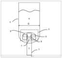
도 1 은 본 발명에 따른 다상 분배 디바이스의 단면도이다. 개구들 (7 및 8), 헤드 (9) 및 유입 튜브 (2) 가 여기에서 식별될 수 있다.
도 2a 는 특히 치수들 (E, F 및 H) 을 도시하는 분배기의 보다 상세한 단면도를 제공한다.
도 2b 는 개구들 (8) 로부터 연장되는 분기부들 (6), 및 노치들 (10) 을 도시하는 분배기의 아래에서 본 도면이다.
도 2c 는, 분기부들 (6) 이 구성되는 방법과 개구들 (7 및 8) 이 교대되는 방법의 보다 양호한 이해를 제공하는 본 발명에 따른 분배기의 아래에서 본 도면이다. 치수들 (A, B, C, D) 은 이러한 도면에 도입된다.
도 2d 는 개구들 (8) 의 높이 (K) 및 분기부들 (6) 의 높이 (L) 를 도시하는 분배기의 단면도이다.
도 3 은 종래 기술에 따른 분배기에 의해 챔버로 도입되는 유체의 분산을 모니터링할 수 있는 3-D 시뮬레이션으로부터 얻어지는 비주얼리제이션 (visualization) 이다.
도 4 는 본 발명에 따른 분배기에 의해 챔버 (5) 로 도입되는 유체의 분산을 모니터링할 수 있는 3-D 시뮬레이션으로부터 얻어지는 비주얼리제이션이다.
도 3 및 도 4 는 텍스트의 끝에 주어진 비교 실시예를 설명하는 역할을 한다.1 is a cross-sectional view of a multiphase dispensing device according to the present invention.
Figure 2a provides a more detailed cross-sectional view of the dispenser, particularly showing dimensions E, F and H.
FIG. 2b is a bottom view of the dispenser showing
Figure 2c is a bottom view of the dispenser according to the invention, which provides a better understanding of how the
2d is a sectional view of the dispenser showing the height K of the
3 is a visualization resulting from a 3-D simulation that can monitor the dispersion of fluid introduced into a chamber by a prior art dispenser.
Figure 4 is a visualization resulting from a 3-D simulation that can monitor the distribution of fluid introduced into the
Figures 3 and 4 serve to explain comparative examples given at the end of the text.
종래 기술의 조사Investigation of the prior art
다상 매체의 분배기 분야에서 종래 기술은 상당히 풍부하고, 가장 근접한 종래 기술만이 이하의 2 개의 문헌들 형태로 종래 기술에 의해 채택될 것이다:The prior art in the field of distributors of multiphase media is quite rich, and only the closest prior art will be taken up by the prior art in the form of the following two documents:
-특허 US 5,571,482 는 "캣 쿨러" 라고 하는 유동층 열교환 디바이스를 사용하여 FCC 재생기에서의 온도 제어를 설명한다. 그 특허는 치수를 명시함 없이 재생기 (칼럼 6/라인 40) 에서 라이저의 상부에 있는 "버섯-캡" 유형의 분배기를 간략하게 언급한다.- Patent US 5,571,482 describes temperature control in an FCC regenerator using a fluidized bed heat exchange device called a "cat cooler". The patent briefly refers to a “mushroom-cap” type distributor at the top of the riser in the regenerator (
-특허 FR 3,006,607 는 H-오일 및 FCC 프로세스에 적용가능한 "버섯-캡" 유형의 분배기를 개시한다. 그 특허는 조밀상 내 경질상의 분배 (유동층 내 기체 또는 액체 내 기체) 를 주장하고, 여기에서 한 번 더 도입될 유체를 운반하는 수단이 있고, 캡 (5) 은 돔 형상의 메인 보디 (6) 를 가지고, 또한 편향 수단 (14) 은 유체를 캡 (5) 의 주변으로 향하도록 구성된다. 주요 요소들의 치수가 명시된다. 본 발명에 따른 디바이스는 특허 FR 3,006,607 에서 개시된 디바이스와 비교하여 반응기 내 경질상의 분배를 상당히 개선시킨다.- Patent FR 3,006,607 discloses a "mushroom-cap" type dispenser applicable to H-oil and FCC processes. The patent claims a distribution of the hard phase in the dense phase (gas in a fluidized bed or gas in a liquid), in which there is a means for conveying the fluid to be introduced once more, and the cap (5) has a dome-shaped main body (6) , and the deflecting means 14 is also configured to direct the fluid to the periphery of the
본 발명의 간략한 설명BRIEF DESCRIPTION OF THE INVENTION
본 발명은 유동화 상태의 중질상을 함유하는 반응 챔버 (5) 내측에서 중질상에 경질상을 분배하기 위한 디바이스로서 규정될 수도 있다.The invention may also be defined as a device for dispensing a light phase into a heavy phase inside a
경질상은 기체, 기체-고체 서스펜션 또는 액체일 수도 있고, 유동화된 중질상은 기체-고체 에멀젼 또는 심지어 석유 분획물 (petroleum fractions) 의 수소처리를 위한 프로세스에서 직면하는 것과 같은 3 상 기체-고체-액체 매체일 수도 있다.The light phase may be a gas, gas-solid suspension or liquid, and the fluidized heavy phase may be a gas-solid emulsion or even a three-phase gas-solid-liquid medium such as encountered in processes for hydrotreating petroleum fractions. may be
본 발명에 따른 분배 디바이스는 반응 챔버 (5) 로 진입하는 경질상을 운반하기 위한 파이프 (1) 를 그의 하부 부분에 포함하고, 상기 파이프 (1) 는 원통형이고 또한 챔버 (5) 의 대칭 축선을 따라 실질적으로 중심 맞춤되며, 또한 상부 부분에서 상기 파이프 (1) 의 측벽에 천공된 제 1 및 제 2 직사각형 개구들 (7, 8) 을 통해 개방된다.The distribution device according to the present invention comprises at its lower part a pipe (1) for conveying the hard phase entering the reaction chamber (5), which pipe (1) is cylindrical and follows the axis of symmetry of the chamber (5). substantially centered along the
개구부들 (7) 이 반응 챔버 (5) 의 유동화 매체로 직접 개방되는 반면, 제 2 개구들 (8) 은 챔버 (5) 의 대칭 축선에 수직한 분기부들 (6) 에 의해 연장되어 유동화 매체가 챔버 (5) 의 주변부에 도달하게 할 수 있다.While the
파이프 (1) 는 그의 상부에서 볼록 헤드 (9) 가 탑재되고, 상기 헤드는 그의 하부 엣지를 따라 모두 균일하게 분포된 노치들 (10) 을 가지고, 또한 상기 헤드 (9) 의 둘레를 넘어서 돌출하는 분기부들 (6) 의 통과를 허용한다.The
제 1 직사각형 개구들 (7) 은 폭 (B) 및 높이 (J) 를 가지고, 즉 통로 단면 (B*J) 을 가지고, 제 2 직사각형 개구들 (8) 은 폭 (A) 및 높이 (K) 를 가지고, 즉 통로 단면 (A*J) 을 가지고, 이들은 경질상이 제 1 개구 및 제 2 개구를 통과함에 따라 경질상의 속도 (v) 가 0.3V ~ 20V, 더 바람직하게는 0.5V ~ 10V 에 포함되는 방식으로 결정되고, V 는 파이프 (1) 내 상기 경질상의 속도를 나타낸다. 이러한 속도 (V) 는 1 m/s ~ 100 m/s, 바람직하게는 3 m/s ~ 30 m/s 이다.The first
제 1 개구 및 제 2 개구 (7, 8) 는 교대로 배열되고, 바람직하게는 통틀어 짝수로 그리고 동일한 개수로 배열된다.The first openings and the
헤드 (9) 의 직경 (I) 은 일반적으로 0.05 G ~ 0.95 G, 바람직하게는 0.2 G ~ 0.8 G, 여전히 더 바람직하게는 0.25 G ~ 0.75 G 이고, G 는 반응 챔버 (5) 의 내부 직경을 나타낸다.The diameter I of the
반응 챔버 (5) 의 대칭 축선과 일치하는 디바이스의 중심 (O) 으로부터 그의 출구 단부까지 측정된 분기부들 (6) 의 길이 (D) 는 0.55 G ~ 0.48 G 이고, 분기부들의 높이 (L) 는 그의 출구 단부에서 1 ~ 10 K 이다.The length (D) of the branches (6) measured from the center (O) of the device coinciding with the axis of symmetry of the reaction chamber (5) to its outlet end is 0.55 G to 0.48 G, and the height (L) of the branches is 1 to 10 K at its outlet end.
노치들 (10) 은 일반적으로 삼각형 또는 직사각형 형상이다.
노치들 (10) 이 직사각형일 때, 그들의 폭은 0.01 F ~ 0.9 F 이고, 그들의 높이는 0.01 F ~ 0.9 F 이다.When the
노치들 (10) 이 삼각형일 때, 삼각형의 높이는 0.01 F ~ 0.9 F 이고, 삼각형의 베이스는 0.01 F ~ 0.9 F 이다.When the
헤드 (9) 는 그의 상부 돔에 걸쳐 오리피스들 (11) 을 일반적으로 구비하고, 상기 오리피스들 (11) 은 1 ~ 100 mm, 바람직하게는 10 ~ 50 mm 의 직경을 갖는다.The
2 개의 재생 단계들을 갖는 촉매 분해하기 위한 프로세스와 관련하여, 본 발명에 따른 디바이스는 제 1 재생 구역으로부터 제 2 난류 유동층 재생 구역으로 촉매를 전달하는데 사용될 수도 있다.In connection with a process for cracking a catalyst having two regeneration stages, the device according to the invention may be used to transfer catalyst from a first regeneration zone to a second turbulent fluidized bed regeneration zone.
바이오매스를 처리하기 위한 프로세스와 관련하여, 본 발명에 따른 디바이스는 바이오매스-처리 반응기의 유동화 매체로 기상 또는 기체-고체 서스펜션을 도입시키는데 사용될 수도 있다.In connection with a process for treating biomass, the device according to the invention may be used to introduce a gaseous or gas-solid suspension into the fluidizing medium of a biomass-treating reactor.
중질 석유 분획물을 소수처리하기 위한 프로세스와 관련하여, 본 발명에 따른 디바이스는 처리될 중질 탄화수소상 및 촉매 입자를 함유하는 유동화 매체로 수소를 도입시키는데 사용될 수도 있다.In connection with a process for hydrophobic treatment of heavy petroleum fractions, the device according to the invention may be used to introduce hydrogen into the fluidization medium containing the heavy hydrocarbon phase to be treated and the catalyst particles.
더 구체적으로, 본 발명에 따른 분배 디바이스는 다음에서 사용될 수도 있다:More specifically, the dispensing device according to the present invention may be used in:
-유동 접촉 분해 (FCC) 프로세스용 반응기들,- reactors for fluid catalytic cracking (FCC) processes,
-예를 들어 접촉 분해 (FCC) 촉매인 촉매 재생용 반응기들,- reactors for catalyst regeneration, for example catalytic cracking (FCC) catalysts,
-촉매들의 유동층을 포함하는 반응기들,- reactors containing a fluidized bed of catalysts,
-반응기 챔버의 저부에서 2 상 기체/액체 또는 기체/고체 유동의 도입으로 상향류에서 작동하는 수소처리 또는 수소분해 반응기들,- hydrotreating or hydrocracking reactors operating in upstream with the introduction of a two-phase gas/liquid or gas/solid flow at the bottom of the reactor chamber;
-"슬러리" 유형의 반응기들,- reactors of the "slurry" type;
-스트리퍼들, 건조기들, 에어레이터들 또는 가습기들, 및- strippers, dryers, aerators or humidifiers, and
-촉매 열분해 반응기들.- Catalytic pyrolysis reactors.
본 발명의 상세한 설명DETAILED DESCRIPTION OF THE INVENTION
본 발명은 분배될 유체의 것보다 높은 명백한 밀도의 단상 또는 다상 유동화 매체에서 단상 또는 2 상 유체의 분배를 위한 디바이스에 관한 것이다. 경질의 유체상은 기체, 또는 액체, 또는 기체-고체 또는 기체-액체 서스펜션, 또는 액체-고체 서스펜션일 수 있고, 서스펜션의 밀도가 반응 챔버의 밀도보다 낮다는 점에서 특징지어 진다. 텍스트의 나머지 부분은 간단히 말해 분배될 경질상에 관한 것이다.The present invention relates to a device for dispensing a single- or two-phase fluid in a single- or multi-phase fluidizing medium of apparent density higher than that of the fluid to be dispensed. The hard fluid phase can be a gas, or a liquid, or a gas-solid or gas-liquid suspension, or a liquid-solid suspension, and is characterized in that the density of the suspension is lower than that of the reaction chamber. The rest of the text is simply about the hard phase to be dispensed.
도 1 은 이하에서 본 발명에 따른 디바이스의 구성을 도시한다. 이는 예를 들어 분배 디바이스가 장착된 반응기 또는 재생기의 챔버일 수도 있는 챔버 (5) 이다.1 shows the configuration of a device according to the present invention below. This is the
튜브 (1) 는 경질의 유체상 (2) 이 조밀한 유체상 (4) 을 함유하는 반응 챔버 (5) 내로 이송되게 한다.Tube (1) allows a light fluid phase (2) to be conveyed into a reaction chamber (5) containing a dense fluid phase (4).
튜브 (1) 는 이것이 다상 유동을 전달하는 경우 바람직하게는 수직이다.
바람직하게는, 튜브 (1) 의 마지막 부분은 반응 챔버 (5) 에 대해 동축으로 배열된다.Preferably, the last part of the tube (1) is arranged coaxially with respect to the reaction chamber (5).
유체 (2) 는 도 1 에 개략적으로 도시되고 도 2 에 상세하게 도시된 분배기 (3) 에 의해 챔버 (5) 내로 도입된다.The
분배 디바이스 (3) 는 파이프 (1) 의 상부 단부에 배치된다. 유체 (2) 는 2 개의 개구 유형들 (7 및 8) 을 통해 챔버 (5) 로 도입된다.A dispensing
-유형 (7) 의 개구들은 폭 (B) 및 높이 (J) 를 갖는다.- openings of type (7) have a width (B) and a height (J).
-유형 (8) 의 개구들은 폭 (A) 및 높이 (k) 를 갖는다.- Apertures of type (8) have a width (A) and a height (k).
유형 (8) 의 개구들은 길이 (D) 의 분기부들 (6) 에 연결되고, 그의 단부들은 폭 (C) 을 갖는다.The openings of type (8) are connected to branches (6) of length (D), the ends of which have a width (C).
돔형 헤드 (9) 로 이루어지는 스프레쉬보드 (splashboard) 는, 헤드 (9) 의 상부에 배열된 오리피스들 (11) 을 통과시킴으로써 또는 이러한 헤드의 측벽들에 배열된 노치들 (10) 을 통과시킴으로써, 챔버 (5) 의 중앙 부분으로 개구들 (7) 을 통해 도입된 유체 (2) 를 보다 양호하게 분배하기 위하여 파이핑 (1) 의 상부에 배열된다.A splashboard made of a
유체 (2) 가 헤드 (9) 주위에 위치된 주변부에 도달하게 하기 위하여, 그의 개구들이 개구들 (8) 에 대응하는 분기부들 (6) 은 개구들 (8) 을 통과하는 유체를 운반한다. 이러한 분기부들 (6) 은 폭 (C) 의 출구 단부들을 통해 유체 (2) 를 환형 구역으로 분배한다.In order for the
파이프 (1) 내 유체 (2) 는 V 로 표시된 속도를 갖는다.The fluid (2) in the pipe (1) has a velocity denoted by V.
기체의 경우에, 속도 (V) 는 1 ~ 100 m/s, 더 바람직하게는 3 ~ 30 m/s 이다.In the case of gas, the velocity (V) is 1 to 100 m/s, more preferably 3 to 30 m/s.
기체-고체 서스펜션의 경우에, 기체의 속도는 3 ~ 30 m/s, 바람직하게는 6 ~ 25 m/s 이고, 운반된 고체들의 유동은 5 ~ 1000 kg/s/m2, 바람직하게는 50 ~ 600 kg/s/m2 이다.In the case of a gas-solid suspension, the velocity of the gas is 3 to 30 m/s, preferably 6 to 25 m/s, and the flow of the conveyed solids is 5 to 1000 kg/s/m2 , preferably 50 ~ 600 kg/s/m2 .
개구들 (7 및 8) 의 총 개수는 바람직하게는 짝수이고, 2 ~ 48, 바람직하게는 4 ~ 24, 바람직하게는 8 ~ 12 일 것이다.The total number of
개구들 (8) 은 분기부들 (6) 에 연결된다. 유형 (8) 개구들의 개수는 개구들의 총 개수의 10 % ~ 80 %, 바람직하게는 개구들의 총 개수의 40 % ~ 60 %, 바람직하게는 개구들의 총 개수의 50 % 를 나타낼 수도 있다.The
유형 (7) 개구들의 치수들 (B, J) 및 유형 (8) 개구들의 치수들 (A, K) 은 0.3V ~ 20V, 바람직하게는 0.5V ~ 10V, 바람직하게는 V 인 개구들 내 유체들 (2) 에 대한 속도를 가지기 위해 선택된다.The dimensions of the type (7) openings (B, J) and the dimensions (A, K) of the type (8) openings are between 0.3V and 20V, preferably between 0.5V and 10V, preferably V. s (2) is chosen to have a velocity for
바람직하게는, 유형 (7) 개구들의 개수는 유형 (8) 개구들의 개수와 같고, 개구들은 튜브 (1) 의 주변에서 균일하게 교대한다.Preferably, the number of type (7) openings is equal to the number of type (8) openings, and the openings alternate uniformly around the tube (1).
유형 (7) 개구들의 치수들 (B, J) 은 유형 (8) 개구들의 치수들 (A, K) 과 상이할 수도 있다. 유형 (7) 개구들 및 유형 (8) 개구들의 표면 영역은 이러한 2 개의 유형들의 개구들 사이에 유체 (2) 의 원하는 부피 분배에 비례한다. 따라서, 헤드 (9) 가 반응기 (5) 의 통과 단면의 절반을 커버하면, 그 때 헤드 (9) 에 의해 커버된 단면에 공급되는 유형 (7) 개구들을 통과하는 유속은 개구들 (8) 과 주변 섹션에 공급되는 분기부들 (6) 을 통과하는 유속과 같을 것이다. 동일한 개수의 개구들 (7 및 8) 로, 2 개의 유형들의 개구들에 대해 유사한 치수들을 가질 수 있다.The dimensions (B, J) of type (7) openings may differ from the dimensions (A, K) of type (8) openings. The surface area of type (7) openings and type (8) openings is proportional to the desired volume distribution of fluid (2) between these two types of openings. Thus, if the
헤드 (9) 의 직경 (I) 은 0.05 G ~ 0.95 G, 바람직하게는 0.2 G ~ 0.8 G, 여전히 더 바람직하게는 0.65 G ~ 0.75 G 이다. 구멍들 (11) 의, 노치들 (10) 의 그리고 헤드 (9) 의 높이의 디자인은 문헌 FR 3 006 607 에 따른다.The diameter I of the
분기부들 (6) 의 상부벽은 바람직하게는 수평이다. 분기부들 (6) 의 하부 섹션은 바람직하게는 기체/고체 유동의 경우에 설테이션 (saltation) 현상을 회피하기 위하여 개방된다.The upper walls of the
측벽들은 1 ~ 10 K, 바람직하게는 1 ~ 7 K, 바람직하게는 1.2 ~ 3 K 의 높이 (L) 를 갖는다.The sidewalls have a height (L) of 1 to 10K, preferably 1 to 7K, preferably 1.2 to 3K.
유체 (2) 가 주로 분기부들 (6) 의 단부들을 통과하는 것을 보장하기 위해, 분기부를 따라서 통과하는데 필요한 운동 에너지가 유체 (2) 가 분기부들의 측벽을 통해 유동하게 하는데 필요한 잠재적 에너지와 같거나 보다 작은 것이 바람직하다.To ensure that the

v 는 개구 (8) 내 유체의 속도이고,ρ4 는 (4) 로 표시된 조밀한 유체상의 밀도이고,ρ2 는 (2) 로 표시된 분배될 유체상의 밀도이다. 분기부에 의해 형성된 통과 단면은 일정하거나 가변적일 수도 있다.v is the velocity of the fluid in the opening (8),ρ4 is the density of the dense fluid phase denoted by (4), andρ2 is the density of the fluid phase to be distributed denoted by (2). The passage cross-section formed by the branching portion may be constant or variable.
분기부들 (6) 의 단부는 0.1 A ~ 10 A, 바람직하게는 0.5 A ~ 7 A, 바람직하게는 1 ~ 5 A 의 폭 (C) 을 가지고, A 는 유형 (8) 개구들의 입구에서의 폭이다.The ends of the
길이 (E) 는 0 ~ F, 바람직하게는 0.1 ~ 0.9 F, 바람직하게는 0.2 ~ 0.7 F 이고, F 는 헤드 (9) 의 하부 부분의 높이다.The length E is 0 to F, preferably 0.1 to 0.9 F, preferably 0.2 to 0.7 F, where F is the height of the lower part of the
E 는 분기부들의 상부 섹션과 노치들 (10) 의 베이스 사이의 거리이고, F 는 헤드 (9) 의 하부 부분의 높이, 즉 보다 구체적으로 (11) 과 같은 천공부를 포함하지 않는 헤드의 그러한 부분의 높이이다.E is the distance between the upper section of the branches and the base of the
본 발명에 따른 분배 디바이스는 프로세스의 필요에 따라 추가의 기체를 도입하기 위해 분배기 (3) 위 또는 아래에 위치된 분배링에 의해 보충될 수도 있다. 바람직하게는, 상기 링은, 존재하는 경우, 혼합을 촉진시키기 위해 개구들 (7 및 8) 의 최하부 부분 아래에 위치된다.The distribution device according to the invention may be supplemented by a distribution ring located above or below the
본 발명에 따른 실시예들Embodiments According to the Invention
이하의 2 개의 실시예들은 종래 기술에 따른 경우 및 본 발명에 따른 경우에 대응한다.The following two embodiments correspond to the case according to the prior art and the case according to the present invention.
경질상에 대응하는 유체 (2) 는 반응 챔버 내에 함유된 보다 조밀한 유동화 매체로 분배된다.The
한편으로는 종래 기술에 따른 그리고 다른 한편으로는 본 발명에 따른 3-D CFD 실뮬레이션들은 실행되었고, 각각 도 3 및 도 4 에 의해 시각화될 수 있다.3-D CFD simulations according to the prior art on the one hand and according to the invention on the other hand have been implemented and can be visualized by means of FIGS. 3 and 4 , respectively.
이하의 표 1 은 종래 기술에 따른 그리고 본 발명에 따른 분배기들의 작동 조건 및 치수들을 나타낸다. 특정값들은 실시예에서 사용된 것들이다.Table 1 below shows the operating conditions and dimensions of distributors according to the prior art and according to the present invention. Specific values are those used in the examples.

표 1: 종래기술에 따른 그리고 본 발명에 따른 디바이스의 치수들Table 1: Dimensions of the device according to the prior art and according to the invention
도 3 및 도 4 는 각각 종래 기술에 따른 디바이스의 경우 (도 3) 에 그리고 본 발명에 따른 디바이스의 경우 (도 4) 에, 입구 튜브 (1) 로부터 들어오는 보다 고밀도의 유체에서 분배될 경질상의 경로를 도시한다.3 and 4 respectively show the path of the hard phase to be distributed in the denser fluid coming from the
본 발명에 따른 디바이스로, 입구 튜브로부터 들어오는 가스의 분배가 보다 양호하고, 반응 챔버 (5) 의 대부분은 커버된다. 유체 (2) 는 종래 기술의 디바이스에 대한 27 % 와 비교하여 분배기 (3) 위의 체적의 대략 70% 를 차지한다.With the device according to the invention, the distribution of the incoming gas from the inlet tube is better and most of the
따라서, 경질상은 충분히 분산되고, 보다 효과적으로 조밀상과 상호 작용하여, 종래 기술의 특허에 비해 반응기의 성능을 향상시킨다.Thus, the hard phase is sufficiently dispersed and interacts with the dense phase more effectively, improving reactor performance over prior art patents.
Claims (12)
Translated fromKorean상기 디바이스는 상기 반응 챔버 (5) 에 진입하는 상기 경질상을 운반하기 위한 파이프 (1) 를 하부 부분에 포함하고, 상기 파이프 (1) 는 원통형이고 또한 상기 반응 챔버 (5) 의 대칭 축선을 따라서 실질적으로 중심 맞춤 (centred) 되고, 또한 상부 부분에서 상기 파이프 (1) 의 측벽에 천공된 직사각형의 제 1 개구들 및 제 2 개구들 (7, 8) 을 통해 개방되고, 상기 제 2 개구들 (8) 은 상기 반응 챔버 (5) 의 대칭 축선에 수직한 분기부들 (6) 에 의해 연장되고, 상기 파이프 (1) 는 상부 부분에 볼록한 헤드 (9) 가 얹어지고, 상기 헤드 (9) 는 그의 하부 엣지를 따라서 모두 균일하게 분포되는 노치들 (10) 을 가지고, 또한 상기 헤드 (9) 의 주변을 넘어서 돌출하는 분기부들 (6) 의 통과를 허용하는, 경질상을 분배하기 위한 디바이스.A device for dispensing a light phase into a heavy phase inside a reaction chamber (5) containing the heavy phase in a fluidized state,
The device comprises at its lower part a pipe (1) for conveying the hard phase entering the reaction chamber (5), the pipe (1) being cylindrical and along the axis of symmetry of the reaction chamber (5). substantially centered and open through rectangular first openings and second openings 7, 8 perforated in the side wall of the pipe 1 at the upper part, the second openings ( 8) is extended by branches 6 perpendicular to the axis of symmetry of the reaction chamber 5, the pipe 1 being topped with a convex head 9, which is A device for dispensing a hard phase, having notches (10) all equally distributed along the lower edge, and also allowing the passage of branches (6) protruding beyond the periphery of the head (9).
상기 제 1 개구들 (7) 은 폭 (B) 및 높이 (J) 를 가지고, 상기 제 2 개구들 (8) 은 폭 (A) 및 높이 (K) 를 가지고, 이들은 경질상이 상기 제 1 개구 및 상기 제 2 개구를 통과함에 따라 상기 경질상의 속도 (v) 가 0.3V ~ 20V, 또는 0.5V ~ 10V 에 포함되는 방식으로 결정되고, V 는 상기 파이프 (1) 내의 상기 경질상의 속도를 나타내는, 경질상을 분배하기 위한 디바이스.According to claim 1,
The first openings 7 have a width B and a height J, and the second openings 8 have a width A and a height K, which are rigid phases of the first opening and The hard phase velocity (v) as it passes through the second opening is determined in such a way that it is comprised between 0.3V and 20V, or between 0.5V and 10V, and V represents the velocity of the hard phase in the pipe (1). A device for dispensing prizes.
상기 반응 챔버 (5) 의 대칭 축선과 일치하는 상기 디바이스의 중심 (O) 으로부터 출구 단부까지 측정된 상기 분기부들 (6) 의 길이 (D) 는 0.6 G ~ 0.95 G 이고, G 는 상기 반응 챔버 (5) 의 내부 직경을 나타내고, 상기 분기부들 (6) 의 높이 (L) 는 출구 단부에서 1 ~ 10 K 이고, K 는 상기 제 2 개구들 (8) 의 높이를 나타내는, 경질상을 분배하기 위한 디바이스.According to claim 1,
The length (D) of the branches (6) measured from the center (O) of the device coincident with the axis of symmetry of the reaction chamber (5) to the outlet end is 0.6 G to 0.95 G, G is the reaction chamber ( 5), the height L of the branches 6 is 1 to 10 K at the outlet end, and K represents the height of the second openings 8, for dispensing the hard phase. device.
상기 제 1 개구 및 상기 제 2 개구 (7, 8) 는 교대로, 또는 통틀어 짝수로, 또는 동일한 개수로 배열되는, 경질상을 분배하기 위한 디바이스.According to claim 1,
The device for dispensing the hard phase, wherein the first opening and the second opening (7, 8) are arranged alternately, or in an even number in total, or in equal numbers.
상기 헤드 (9) 의 직경 (I) 은 0.05 G ~ 0.95 G, 또는 0.2 G ~ 0.8 G, 또는 0.25 G ~ 0.75 G 이고, G 는 상기 반응 챔버 (5) 의 내부 직경을 나타내는, 경질상을 분배하기 위한 디바이스.According to claim 1,
The diameter I of the head 9 is 0.05 G to 0.95 G, or 0.2 G to 0.8 G, or 0.25 G to 0.75 G, G representing the inner diameter of the reaction chamber 5, distributing the hard phase. device to do it.
상기 노치들 (10) 은 삼각형 또는 직사각형 형상인, 경질상을 분배하기 위한 디바이스.According to claim 1,
The device for dispensing the hard phase, wherein the notches (10) are triangular or rectangular in shape.
상기 노치들 (10) 이 직사각형일 때, 그들의 폭은 0.01 F ~ 0.9 F 이고, 그들의 높이는 0.01 F ~ 0.9 F 이고, F 는 상기 헤드 (9) 의 하부 부분의 높이인, 경질상을 분배하기 위한 디바이스.According to claim 1,
When the notches (10) are rectangular, their width is between 0.01 F and 0.9 F, and their height is between 0.01 F and 0.9 F, where F is the height of the lower part of the head (9) for dispensing the hard phase. device.
상기 노치들 (10) 이 삼각형일 때, 상기 삼각형의 높이는 0.01 F ~ 0.9 F 이고, 상기 삼각형의 베이스는 0.01 F ~ 0.9 F 이고, F 는 상기 헤드 (9) 의 하부 부분의 높이인, 경질상을 분배하기 위한 디바이스.According to claim 1,
When the notches 10 are triangular, the height of the triangle is between 0.01 F and 0.9 F, and the base of the triangle is between 0.01 F and 0.9 F, where F is the height of the lower part of the head 9, in the hard phase. A device for distributing.
상기 헤드 (9) 는 그의 상부 돔에 걸쳐 오리피스들 (11) 을 갖고, 상기 오리피스들 (11) 은 1 ~ 100 mm, 또는 10 ~ 50 mm 의 직경을 가지는, 경질상을 분배하기 위한 디바이스.According to claim 1,
The device for dispensing a hard phase, wherein the head (9) has orifices (11) across its upper dome, the orifices (11) having a diameter of 1 to 100 mm, or 10 to 50 mm.
촉매를 제 1 재생 구역으로부터 제 2 난류 유동층 재생 구역으로 전달하기 위해 제 1 항 내지 제 9 항 중 어느 한 항에 따른 디바이스를 사용하는, 접촉 분해를 위한 프로세스.As a process for catalytic cracking with two regeneration zones,
A process for catalytic cracking, using a device according to any one of claims 1 to 9 for conveying catalyst from a first regeneration zone to a second turbulent fluidized bed regeneration zone.
기체상 또는 기체-고체 서스펜션을 유동화 매체로 도입시키기 위해 제 1 항 내지 제 9 항 중 어느 한 항에 따른 디바이스를 사용하는, 바이오매스를 처리하기 위한 프로세스.As a process for treating biomass,
A process for treating biomass, using a device according to any one of claims 1 to 9 for introducing a gaseous or gaseous-solid suspension into a fluidizing medium.
수소를 처리될 중질 탄화수소상 및 촉매 입자를 함유하는 유동화 매체로 도입시키기 위해 제 1 항 내지 제 9 항 중 어느 한 항에 따른 디바이스를 사용하는, 중질 석유 분획물의 수소처리를 위한 프로세스.As a process for the hydrotreating of heavy petroleum fractions,
A process for the hydrotreating of heavy petroleum fractions, using a device according to any one of claims 1 to 9 to introduce hydrogen into a fluidizing medium containing catalyst particles and a heavy hydrocarbon phase to be treated.
Applications Claiming Priority (3)
| Application Number | Priority Date | Filing Date | Title |
|---|---|---|---|
| FR1754006 | 2017-05-05 | ||
| FR1754006AFR3065886B1 (en) | 2017-05-05 | 2017-05-05 | NEW DEVICE FOR DISTRIBUTION OF POLYPHASIC MIXTURE IN AN ENCLOSURE COMPRISING A FLUIDIZED MEDIUM |
| PCT/EP2018/060799WO2018202554A1 (en) | 2017-05-05 | 2018-04-26 | Novel device for distributing a polyphase mixture in a chamber comprising a fluidised medium |
Publications (2)
| Publication Number | Publication Date |
|---|---|
| KR20200004339A KR20200004339A (en) | 2020-01-13 |
| KR102532376B1true KR102532376B1 (en) | 2023-05-12 |
Family
ID=59930432
Family Applications (1)
| Application Number | Title | Priority Date | Filing Date |
|---|---|---|---|
| KR1020197035165AActiveKR102532376B1 (en) | 2017-05-05 | 2018-04-26 | A novel device for dispensing a multiphase mixture in a chamber containing a fluidizing medium |
Country Status (10)
| Country | Link |
|---|---|
| US (1) | US11000820B2 (en) |
| EP (1) | EP3618947B1 (en) |
| JP (1) | JP7158412B2 (en) |
| KR (1) | KR102532376B1 (en) |
| CN (1) | CN110769927B (en) |
| CA (1) | CA3060196A1 (en) |
| FR (1) | FR3065886B1 (en) |
| RU (1) | RU2753712C2 (en) |
| SA (1) | SA519410484B1 (en) |
| WO (1) | WO2018202554A1 (en) |
Families Citing this family (4)
| Publication number | Priority date | Publication date | Assignee | Title |
|---|---|---|---|---|
| US11266923B2 (en) | 2019-04-24 | 2022-03-08 | Technip Process Technology, Inc. | Fluid distribution devices |
| FR3123361A1 (en) | 2021-05-31 | 2022-12-02 | IFP Energies Nouvelles | Device and process for catalytic cracking with heat input for the treatment of low coking feedstocks. |
| FR3130287A1 (en) | 2021-12-09 | 2023-06-16 | IFP Energies Nouvelles | Catalytic cracking of low coking feedstocks with heat input by external burner |
| FR3144024B1 (en) | 2022-12-22 | 2025-07-04 | Ifp Energies Now | Fluidized bed distributor |
Citations (2)
| Publication number | Priority date | Publication date | Assignee | Title |
|---|---|---|---|---|
| US20140360919A1 (en)* | 2013-06-11 | 2014-12-11 | Axens | Fluid distribution device |
| CN104923131A (en)* | 2014-03-19 | 2015-09-23 | 中石化洛阳工程有限公司 | Gas-liquid distributor used for wood tar fluidized bed reactor |
Family Cites Families (23)
| Publication number | Priority date | Publication date | Assignee | Title |
|---|---|---|---|---|
| US2841476A (en) | 1953-07-16 | 1958-07-01 | Dorr Oliver Inc | Apparatus for contacting solids with gases |
| US3672577A (en) | 1970-10-15 | 1972-06-27 | Fuller Co | Fluid bed grid plate assembly |
| EP0136139B1 (en) | 1983-09-16 | 1990-06-13 | Hambro Machinery Limited | Distribution means |
| US4787791A (en)* | 1986-10-31 | 1988-11-29 | Amoco Corporation | Lock washer for bubble cap assembly |
| US4859430A (en)* | 1987-06-29 | 1989-08-22 | Uop | Air distribution device |
| US4874583A (en)* | 1987-11-27 | 1989-10-17 | Texaco Inc. | Bubble cap assembly in an ebullated bed reactor |
| RU2001673C1 (en)* | 1989-04-04 | 1993-10-30 | А.Альстрем Корпорейшн (FI) | Fluidized-bed reaction vessel and method for delivery of fluid thereinto |
| US5571482A (en) | 1992-04-27 | 1996-11-05 | Stone & Webster Engineering Corporation | Apparatus for controlling catalyst temperature during regeneration |
| FR2690512B1 (en)* | 1992-04-27 | 1994-09-09 | Stein Industrie | Circulating fluidized bed reactor comprising external exchangers fed by internal recirculation. |
| TW351683B (en)* | 1993-04-21 | 1999-02-01 | Shell Int Research | Process for radially distributing a dispersion of particles in a fluid into a mass of particles dispersed in a fluid |
| RU2107540C1 (en)* | 1994-03-21 | 1998-03-27 | Металлгезельшафт Актиенгезельшафт | Apparatus for conduction of catalytic reaction in fluidized bed |
| US5575086A (en)* | 1994-09-16 | 1996-11-19 | Combustion Engineering, Inc. | Fluidized bed with improved nozzle construction |
| US5635140A (en)* | 1995-11-13 | 1997-06-03 | The M. W. Kellogg Company | Self-aerating spent catalyst distributor |
| US6797239B1 (en)* | 2000-11-22 | 2004-09-28 | Shell Oil Company | Spent catalyst distributor |
| US8211375B2 (en)* | 2009-10-07 | 2012-07-03 | Chevron U.S.A. Inc. | Flow distribution device for downflow catalytic reactors |
| CN102989528A (en)* | 2011-09-15 | 2013-03-27 | 中国石油化工股份有限公司 | Catalyst regeneration method and device with catalytic cracking device heat replenished |
| CN103240038B (en)* | 2012-02-03 | 2015-04-08 | 中国石油化工股份有限公司 | Gas distributor for slurry bed reactor |
| CN104174339B (en)* | 2013-05-22 | 2016-08-10 | 中石化洛阳工程有限公司 | A kind of gas distributor for paste state bed reactor |
| CN104338494B (en)* | 2013-08-03 | 2016-09-14 | 中石化洛阳工程有限公司 | Gas distributor for paste state bed reactor |
| CN105080438B (en)* | 2014-05-15 | 2017-10-24 | 中石化洛阳工程有限公司 | A kind of gas-liquid distributor for fluidized bed reactor |
| CN106606998B (en)* | 2015-10-23 | 2020-03-24 | 中国石油化工股份有限公司 | Upflow distributor and upflow reactor |
| CN205288354U (en)* | 2016-01-07 | 2016-06-08 | 中石化炼化工程(集团)股份有限公司 | Gas -liquid distributor |
| CN105435720B (en)* | 2016-01-07 | 2018-06-19 | 中石化炼化工程(集团)股份有限公司 | Gas-liquid distributor |
- 2017
- 2017-05-05FRFR1754006Apatent/FR3065886B1/enactiveActive
- 2018
- 2018-04-26CNCN201880029931.0Apatent/CN110769927B/enactiveActive
- 2018-04-26USUS16/610,669patent/US11000820B2/enactiveActive
- 2018-04-26CACA3060196Apatent/CA3060196A1/enactivePending
- 2018-04-26JPJP2019559794Apatent/JP7158412B2/enactiveActive
- 2018-04-26RURU2019139264Apatent/RU2753712C2/enactive
- 2018-04-26WOPCT/EP2018/060799patent/WO2018202554A1/ennot_activeCeased
- 2018-04-26KRKR1020197035165Apatent/KR102532376B1/enactiveActive
- 2018-04-26EPEP18720253.6Apatent/EP3618947B1/enactiveActive
- 2019
- 2019-11-04SASA519410484Apatent/SA519410484B1/enunknown
Patent Citations (2)
| Publication number | Priority date | Publication date | Assignee | Title |
|---|---|---|---|---|
| US20140360919A1 (en)* | 2013-06-11 | 2014-12-11 | Axens | Fluid distribution device |
| CN104923131A (en)* | 2014-03-19 | 2015-09-23 | 中石化洛阳工程有限公司 | Gas-liquid distributor used for wood tar fluidized bed reactor |
Also Published As
| Publication number | Publication date |
|---|---|
| US20200147575A1 (en) | 2020-05-14 |
| WO2018202554A1 (en) | 2018-11-08 |
| CA3060196A1 (en) | 2018-11-08 |
| RU2019139264A (en) | 2021-06-07 |
| US11000820B2 (en) | 2021-05-11 |
| EP3618947B1 (en) | 2022-08-24 |
| FR3065886A1 (en) | 2018-11-09 |
| JP2020518449A (en) | 2020-06-25 |
| RU2019139264A3 (en) | 2021-07-15 |
| FR3065886B1 (en) | 2021-12-31 |
| EP3618947A1 (en) | 2020-03-11 |
| SA519410484B1 (en) | 2022-12-19 |
| CN110769927B (en) | 2022-04-12 |
| JP7158412B2 (en) | 2022-10-21 |
| CN110769927A (en) | 2020-02-07 |
| KR20200004339A (en) | 2020-01-13 |
| RU2753712C2 (en) | 2021-08-20 |
Similar Documents
| Publication | Publication Date | Title |
|---|---|---|
| KR102532376B1 (en) | A novel device for dispensing a multiphase mixture in a chamber containing a fluidizing medium | |
| CN100430458C (en) | Mixing device for mixing fluids, multi-bed downflow reactor and application | |
| EP2435172B1 (en) | Mixing device for a down-flow catalytic reactor | |
| JP6110847B2 (en) | Apparatus and method for hydrogen conversion | |
| EP1721660A1 (en) | Distributor system for downflow reactors comprising subdivided chimney chamber | |
| CN101628216B (en) | Treatment or hydrotreatment reactor | |
| CN1005063B (en) | Backmixing hydroprocessing reactor | |
| CN111065452B (en) | Method and apparatus for fluid contact in a downflow vessel | |
| JP2024120906A (en) | Improved mixing device for downflow hydroprocessing reactors | |
| US4707340A (en) | Staged guide plate and vessel assembly | |
| KR20190138748A (en) | Device for distributing a polyphase mixture in a chamber containing a fluidized medium | |
| JP2020518449A5 (en) | ||
| CN100482765C (en) | Catalyst for conversion processes | |
| CN111050900A (en) | Method and apparatus for fluid contact in a downflow vessel | |
| RU2596767C2 (en) | Distribution tray for distributing a polyphasic mixture with inclined peripheral conduits | |
| EP3658267B1 (en) | Methods for fluid contacting in a downflow vessel | |
| CA1237874A (en) | Staged flow distribution grid assembly and method for ebullated bed reactor | |
| US12427491B2 (en) | Gas distributor for bubble column reactor | |
| KR101535058B1 (en) | Slurry bubble column reactor | |
| US8906319B2 (en) | Distributor plate for the distribution of a polyphase mixture with periphery-truncated shafts | |
| KR101692379B1 (en) | Fluid distributor and multi trickle-bed catalytic reactors with the same | |
| JPS61287438A (en) | Dispersing device for three phase fluidized bed reactor | |
| CN102430365A (en) | Device for distributing a multiphase mixture, comprising a jet breaker tray with a separating element | |
| JPH0453579B2 (en) |
Legal Events
| Date | Code | Title | Description |
|---|---|---|---|
| PA0105 | International application | Patent event date:20191127 Patent event code:PA01051R01D Comment text:International Patent Application | |
| PG1501 | Laying open of application | ||
| PA0201 | Request for examination | Patent event code:PA02012R01D Patent event date:20210402 Comment text:Request for Examination of Application | |
| PE0902 | Notice of grounds for rejection | Comment text:Notification of reason for refusal Patent event date:20220920 Patent event code:PE09021S01D | |
| E701 | Decision to grant or registration of patent right | ||
| PE0701 | Decision of registration | Patent event code:PE07011S01D Comment text:Decision to Grant Registration Patent event date:20230322 | |
| GRNT | Written decision to grant | ||
| PR0701 | Registration of establishment | Comment text:Registration of Establishment Patent event date:20230510 Patent event code:PR07011E01D | |
| PR1002 | Payment of registration fee | Payment date:20230510 End annual number:3 Start annual number:1 | |
| PG1601 | Publication of registration |