KR102531924B1 - Implantable Electrode and Method for Preparing the Same - Google Patents
Implantable Electrode and Method for Preparing the SameDownload PDFInfo
- Publication number
- KR102531924B1 KR102531924B1KR1020210049112AKR20210049112AKR102531924B1KR 102531924 B1KR102531924 B1KR 102531924B1KR 1020210049112 AKR1020210049112 AKR 1020210049112AKR 20210049112 AKR20210049112 AKR 20210049112AKR 102531924 B1KR102531924 B1KR 102531924B1
- Authority
- KR
- South Korea
- Prior art keywords
- layer
- electrode
- self
- electrically conductive
- platinum black
- Prior art date
- Legal status (The legal status is an assumption and is not a legal conclusion. Google has not performed a legal analysis and makes no representation as to the accuracy of the status listed.)
- Active
Links
- 238000000034methodMethods0.000titleclaimsabstractdescription19
- 239000010410layerSubstances0.000claimsabstractdescription118
- BASFCYQUMIYNBI-UHFFFAOYSA-NplatinumChemical compound[Pt]BASFCYQUMIYNBI-UHFFFAOYSA-N0.000claimsabstractdescription66
- 239000013545self-assembled monolayerSubstances0.000claimsabstractdescription38
- 239000002094self assembled monolayerSubstances0.000claimsabstractdescription37
- 239000000314lubricantSubstances0.000claimsabstractdescription28
- 238000001727in vivoMethods0.000claimsabstractdescription18
- 239000000758substrateSubstances0.000claimsabstractdescription13
- 238000004519manufacturing processMethods0.000claimsabstractdescription6
- 229910052751metalInorganic materials0.000claimsdescription35
- 239000002184metalSubstances0.000claimsdescription35
- 238000009713electroplatingMethods0.000claimsdescription12
- 229910052697platinumInorganic materials0.000claimsdescription9
- 238000000151depositionMethods0.000claimsdescription8
- 239000010702perfluoropolyetherSubstances0.000claimsdescription7
- 239000000463materialSubstances0.000claimsdescription5
- 229910052760oxygenInorganic materials0.000claimsdescription5
- -1polytetrafluoroethylenePolymers0.000claimsdescription5
- 239000004813Perfluoroalkoxy alkaneSubstances0.000claimsdescription4
- SLYCYWCVSGPDFR-UHFFFAOYSA-NoctadecyltrimethoxysilaneChemical compoundCCCCCCCCCCCCCCCCCC[Si](OC)(OC)OCSLYCYWCVSGPDFR-UHFFFAOYSA-N0.000claimsdescription4
- 229920011301perfluoro alkoxyl alkanePolymers0.000claimsdescription4
- 229920001343polytetrafluoroethylenePolymers0.000claimsdescription4
- 239000004810polytetrafluoroethyleneSubstances0.000claimsdescription4
- 239000002243precursorSubstances0.000claimsdescription4
- 238000004381surface treatmentMethods0.000claimsdescription4
- 101710162828Flavin-dependent thymidylate synthaseProteins0.000claimsdescription3
- 101710135409Probable flavin-dependent thymidylate synthaseProteins0.000claimsdescription3
- LIKFHECYJZWXFJ-UHFFFAOYSA-NdimethyldichlorosilaneChemical compoundC[Si](C)(Cl)ClLIKFHECYJZWXFJ-UHFFFAOYSA-N0.000claimsdescription3
- 229950011087perflunafeneDrugs0.000claimsdescription3
- UWEYRJFJVCLAGH-IJWZVTFUSA-NperfluorodecalinChemical compoundFC1(F)C(F)(F)C(F)(F)C(F)(F)[C@@]2(F)C(F)(F)C(F)(F)C(F)(F)C(F)(F)[C@@]21FUWEYRJFJVCLAGH-IJWZVTFUSA-N0.000claimsdescription3
- QKENRHXGDUPTEM-UHFFFAOYSA-NperfluorophenanthreneChemical compoundFC1(F)C(F)(F)C(F)(F)C(F)(F)C2(F)C3(F)C(F)(F)C(F)(F)C(F)(F)C(F)(F)C3(F)C(F)(F)C(F)(F)C21FQKENRHXGDUPTEM-UHFFFAOYSA-N0.000claimsdescription3
- PISDRBMXQBSCIP-UHFFFAOYSA-Ntrichloro(3,3,4,4,5,5,6,6,7,7,8,8,8-tridecafluorooctyl)silaneChemical compoundFC(F)(F)C(F)(F)C(F)(F)C(F)(F)C(F)(F)C(F)(F)CC[Si](Cl)(Cl)ClPISDRBMXQBSCIP-UHFFFAOYSA-N0.000claimsdescription3
- VIFIHLXNOOCGLJ-UHFFFAOYSA-Ntrichloro(3,3,4,4,5,5,6,6,7,7,8,8,9,9,10,10,10-heptadecafluorodecyl)silaneChemical compoundFC(F)(F)C(F)(F)C(F)(F)C(F)(F)C(F)(F)C(F)(F)C(F)(F)C(F)(F)CC[Si](Cl)(Cl)ClVIFIHLXNOOCGLJ-UHFFFAOYSA-N0.000claimsdescription3
- 238000009832plasma treatmentMethods0.000claimsdescription2
- CHBOSHOWERDCMH-UHFFFAOYSA-N1-chloro-2,2-bis(4-chlorophenyl)ethaneChemical compoundC=1C=C(Cl)C=CC=1C(CCl)C1=CC=C(Cl)C=C1CHBOSHOWERDCMH-UHFFFAOYSA-N0.000claims1
- BLRPTPMANUNPDV-UHFFFAOYSA-NSilaneChemical compound[SiH4]BLRPTPMANUNPDV-UHFFFAOYSA-N0.000claims1
- 229910000077silaneInorganic materials0.000claims1
- QRPMCZNLJXJVSG-UHFFFAOYSA-Ntrichloro(1,1,2,2,3,3,4,4,5,5,6,6,7,7,8,8,9,9,10,10,10-henicosafluorodecyl)silaneChemical compoundFC(F)(F)C(F)(F)C(F)(F)C(F)(F)C(F)(F)C(F)(F)C(F)(F)C(F)(F)C(F)(F)C(F)(F)[Si](Cl)(Cl)ClQRPMCZNLJXJVSG-UHFFFAOYSA-N0.000claims1
- 238000003780insertionMethods0.000abstractdescription12
- 230000037431insertionEffects0.000abstractdescription12
- 208000014674injuryDiseases0.000abstractdescription10
- 230000008733traumaEffects0.000abstractdescription10
- 230000035587bioadhesionEffects0.000abstractdescription7
- 210000004027cellAnatomy0.000abstractdescription6
- 230000007774longtermEffects0.000abstractdescription5
- 108090000623proteins and genesProteins0.000abstractdescription5
- 102000004169proteins and genesHuman genes0.000abstractdescription5
- 210000002865immune cellAnatomy0.000abstractdescription4
- 230000028993immune responseEffects0.000abstractdescription2
- 230000035945sensitivityEffects0.000abstractdescription2
- 210000001519tissueAnatomy0.000description15
- 210000004556brainAnatomy0.000description12
- 241000700159RattusSpecies0.000description10
- 239000004020conductorSubstances0.000description9
- 239000010936titaniumSubstances0.000description9
- 238000011156evaluationMethods0.000description8
- 239000000523sampleSubstances0.000description7
- KFZMGEQAYNKOFK-UHFFFAOYSA-NIsopropanolChemical compoundCC(C)OKFZMGEQAYNKOFK-UHFFFAOYSA-N0.000description6
- 239000010931goldSubstances0.000description6
- 230000001154acute effectEffects0.000description5
- 230000000638stimulationEffects0.000description5
- 239000010949copperSubstances0.000description4
- 238000002474experimental methodMethods0.000description4
- 210000005036nerveAnatomy0.000description4
- 230000001537neural effectEffects0.000description4
- 238000000059patterningMethods0.000description4
- 238000001878scanning electron micrographMethods0.000description4
- 238000012404In vitro experimentMethods0.000description3
- 210000004369bloodAnatomy0.000description3
- 239000008280bloodSubstances0.000description3
- 230000006931brain damageEffects0.000description3
- 231100000874brain damageToxicity0.000description3
- 208000029028brain injuryDiseases0.000description3
- 238000006243chemical reactionMethods0.000description3
- 239000008367deionised waterSubstances0.000description3
- 229910021641deionized waterInorganic materials0.000description3
- 125000002887hydroxy groupChemical group[H]O*0.000description3
- 230000001629suppressionEffects0.000description3
- XLYOFNOQVPJJNP-UHFFFAOYSA-NwaterChemical compoundOXLYOFNOQVPJJNP-UHFFFAOYSA-N0.000description3
- 102000004506Blood ProteinsHuman genes0.000description2
- 108010017384Blood ProteinsProteins0.000description2
- RYGMFSIKBFXOCR-UHFFFAOYSA-NCopperChemical compound[Cu]RYGMFSIKBFXOCR-UHFFFAOYSA-N0.000description2
- 206010061218InflammationDiseases0.000description2
- ZOKXTWBITQBERF-UHFFFAOYSA-NMolybdenumChemical compound[Mo]ZOKXTWBITQBERF-UHFFFAOYSA-N0.000description2
- 239000004642PolyimideSubstances0.000description2
- 229910004298SiO 2Inorganic materials0.000description2
- BQCADISMDOOEFD-UHFFFAOYSA-NSilverChemical compound[Ag]BQCADISMDOOEFD-UHFFFAOYSA-N0.000description2
- RTAQQCXQSZGOHL-UHFFFAOYSA-NTitaniumChemical compound[Ti]RTAQQCXQSZGOHL-UHFFFAOYSA-N0.000description2
- 230000010062adhesion mechanismEffects0.000description2
- 229910045601alloyInorganic materials0.000description2
- 239000000956alloySubstances0.000description2
- 239000000227bioadhesiveSubstances0.000description2
- 210000005013brain tissueAnatomy0.000description2
- 238000011109contaminationMethods0.000description2
- 229910052802copperInorganic materials0.000description2
- 230000008021depositionEffects0.000description2
- 238000001514detection methodMethods0.000description2
- 239000004205dimethyl polysiloxaneSubstances0.000description2
- 239000003814drugSubstances0.000description2
- 239000011521glassSubstances0.000description2
- PCHJSUWPFVWCPO-UHFFFAOYSA-NgoldChemical compound[Au]PCHJSUWPFVWCPO-UHFFFAOYSA-N0.000description2
- 229910052737goldInorganic materials0.000description2
- 230000004054inflammatory processEffects0.000description2
- 229940046892lead acetateDrugs0.000description2
- 239000007788liquidSubstances0.000description2
- 239000007791liquid phaseSubstances0.000description2
- 229910052750molybdenumInorganic materials0.000description2
- 239000011733molybdenumSubstances0.000description2
- 239000002245particleSubstances0.000description2
- 229920000435poly(dimethylsiloxane)Polymers0.000description2
- 229920001721polyimidePolymers0.000description2
- 229910052709silverInorganic materials0.000description2
- 239000004332silverSubstances0.000description2
- 239000002904solventSubstances0.000description2
- 229910052719titaniumInorganic materials0.000description2
- WFKWXMTUELFFGS-UHFFFAOYSA-NtungstenChemical compound[W]WFKWXMTUELFFGS-UHFFFAOYSA-N0.000description2
- 229910052721tungstenInorganic materials0.000description2
- 239000010937tungstenSubstances0.000description2
- 241000894006BacteriaSpecies0.000description1
- 208000030768Optic nerve injuryDiseases0.000description1
- 239000004698PolyethyleneSubstances0.000description1
- ZLMJMSJWJFRBEC-UHFFFAOYSA-NPotassiumChemical compound[K]ZLMJMSJWJFRBEC-UHFFFAOYSA-N0.000description1
- XUIMIQQOPSSXEZ-UHFFFAOYSA-NSiliconChemical compound[Si]XUIMIQQOPSSXEZ-UHFFFAOYSA-N0.000description1
- 229910021607Silver chlorideInorganic materials0.000description1
- 208000020339Spinal injuryDiseases0.000description1
- 208000027418Wounds and injuryDiseases0.000description1
- 239000002253acidSubstances0.000description1
- 239000011543agarose gelSubstances0.000description1
- 210000001130astrocyteAnatomy0.000description1
- QVGXLLKOCUKJST-UHFFFAOYSA-Natomic oxygenChemical compound[O]QVGXLLKOCUKJST-UHFFFAOYSA-N0.000description1
- FOSZYDNAURUMOT-UHFFFAOYSA-Jazane;platinum(4+);tetrachlorideChemical compoundN.N.N.N.[Cl-].[Cl-].[Cl-].[Cl-].[Pt+4]FOSZYDNAURUMOT-UHFFFAOYSA-J0.000description1
- 244000052616bacterial pathogenSpecies0.000description1
- 239000012620biological materialSubstances0.000description1
- 210000000601blood cellAnatomy0.000description1
- 230000003197catalytic effectEffects0.000description1
- 230000008859changeEffects0.000description1
- 239000011247coating layerSubstances0.000description1
- 229920005839ecoflex®Polymers0.000description1
- 230000000694effectsEffects0.000description1
- 238000000609electron-beam lithographyMethods0.000description1
- 238000005265energy consumptionMethods0.000description1
- 238000005516engineering processMethods0.000description1
- 230000001747exhibiting effectEffects0.000description1
- 238000001914filtrationMethods0.000description1
- 239000007789gasSubstances0.000description1
- 239000000499gelSubstances0.000description1
- 238000002847impedance measurementMethods0.000description1
- 238000002513implantationMethods0.000description1
- 238000005259measurementMethods0.000description1
- 244000005700microbiomeSpecies0.000description1
- 210000000274microgliaAnatomy0.000description1
- 238000002156mixingMethods0.000description1
- 210000000944nerve tissueAnatomy0.000description1
- 210000002569neuronAnatomy0.000description1
- 239000001301oxygenSubstances0.000description1
- 239000012071phaseSubstances0.000description1
- 238000000206photolithographyMethods0.000description1
- 229920002120photoresistant polymerPolymers0.000description1
- 230000000704physical effectEffects0.000description1
- 239000004033plasticSubstances0.000description1
- 229920003023plasticPolymers0.000description1
- CLSUSRZJUQMOHH-UHFFFAOYSA-Lplatinum dichlorideChemical compoundCl[Pt]ClCLSUSRZJUQMOHH-UHFFFAOYSA-L0.000description1
- 239000004417polycarbonateSubstances0.000description1
- 229920000515polycarbonatePolymers0.000description1
- 229920000573polyethylenePolymers0.000description1
- 239000011112polyethylene naphthalateSubstances0.000description1
- 229910052700potassiumInorganic materials0.000description1
- 239000011591potassiumSubstances0.000description1
- 239000000843powderSubstances0.000description1
- 238000002360preparation methodMethods0.000description1
- 230000002265preventionEffects0.000description1
- 230000008569processEffects0.000description1
- 230000035755proliferationEffects0.000description1
- 208000020016psychiatric diseaseDiseases0.000description1
- 230000004044responseEffects0.000description1
- 239000010703siliconSubstances0.000description1
- 229910052710siliconInorganic materials0.000description1
- HKZLPVFGJNLROG-UHFFFAOYSA-Msilver monochlorideChemical compound[Cl-].[Ag+]HKZLPVFGJNLROG-UHFFFAOYSA-M0.000description1
- 238000004088simulationMethods0.000description1
- 238000010186stainingMethods0.000description1
- 238000001356surgical procedureMethods0.000description1
- SLIOYUPLNYLSSR-UHFFFAOYSA-Jtetrachloroplatinum;hydrate;dihydrochlorideChemical compoundO.Cl.Cl.Cl[Pt](Cl)(Cl)ClSLIOYUPLNYLSSR-UHFFFAOYSA-J0.000description1
- ZDHXKXAHOVTTAH-UHFFFAOYSA-NtrichlorosilaneChemical groupCl[SiH](Cl)ClZDHXKXAHOVTTAH-UHFFFAOYSA-N0.000description1
- AVYKQOAMZCAHRG-UHFFFAOYSA-Ntriethoxy(3,3,4,4,5,5,6,6,7,7,8,8,8-tridecafluorooctyl)silaneChemical compoundCCO[Si](OCC)(OCC)CCC(F)(F)C(F)(F)C(F)(F)C(F)(F)C(F)(F)C(F)(F)FAVYKQOAMZCAHRG-UHFFFAOYSA-N0.000description1
- 239000012808vapor phaseSubstances0.000description1
Images


Classifications
- A—HUMAN NECESSITIES
- A61—MEDICAL OR VETERINARY SCIENCE; HYGIENE
- A61B—DIAGNOSIS; SURGERY; IDENTIFICATION
- A61B5/00—Measuring for diagnostic purposes; Identification of persons
- A61B5/24—Detecting, measuring or recording bioelectric or biomagnetic signals of the body or parts thereof
- A61B5/25—Bioelectric electrodes therefor
- A61B5/251—Means for maintaining electrode contact with the body
- A—HUMAN NECESSITIES
- A61—MEDICAL OR VETERINARY SCIENCE; HYGIENE
- A61N—ELECTROTHERAPY; MAGNETOTHERAPY; RADIATION THERAPY; ULTRASOUND THERAPY
- A61N1/00—Electrotherapy; Circuits therefor
- A61N1/02—Details
- A61N1/04—Electrodes
- A61N1/05—Electrodes for implantation or insertion into the body, e.g. heart electrode
- A61N1/0526—Head electrodes
- A61N1/0529—Electrodes for brain stimulation
- A—HUMAN NECESSITIES
- A61—MEDICAL OR VETERINARY SCIENCE; HYGIENE
- A61B—DIAGNOSIS; SURGERY; IDENTIFICATION
- A61B5/00—Measuring for diagnostic purposes; Identification of persons
- A61B5/24—Detecting, measuring or recording bioelectric or biomagnetic signals of the body or parts thereof
- A61B5/25—Bioelectric electrodes therefor
- A61B5/263—Bioelectric electrodes therefor characterised by the electrode materials
- A61B5/268—Bioelectric electrodes therefor characterised by the electrode materials containing conductive polymers, e.g. PEDOT:PSS polymers
- A—HUMAN NECESSITIES
- A61—MEDICAL OR VETERINARY SCIENCE; HYGIENE
- A61B—DIAGNOSIS; SURGERY; IDENTIFICATION
- A61B5/00—Measuring for diagnostic purposes; Identification of persons
- A61B5/24—Detecting, measuring or recording bioelectric or biomagnetic signals of the body or parts thereof
- A61B5/25—Bioelectric electrodes therefor
- A61B5/279—Bioelectric electrodes therefor specially adapted for particular uses
- A61B5/291—Bioelectric electrodes therefor specially adapted for particular uses for electroencephalography [EEG]
- A61B5/293—Invasive
- A—HUMAN NECESSITIES
- A61—MEDICAL OR VETERINARY SCIENCE; HYGIENE
- A61B—DIAGNOSIS; SURGERY; IDENTIFICATION
- A61B5/00—Measuring for diagnostic purposes; Identification of persons
- A61B5/24—Detecting, measuring or recording bioelectric or biomagnetic signals of the body or parts thereof
- A61B5/25—Bioelectric electrodes therefor
- A61B5/279—Bioelectric electrodes therefor specially adapted for particular uses
- A61B5/294—Bioelectric electrodes therefor specially adapted for particular uses for nerve conduction study [NCS]
- A—HUMAN NECESSITIES
- A61—MEDICAL OR VETERINARY SCIENCE; HYGIENE
- A61B—DIAGNOSIS; SURGERY; IDENTIFICATION
- A61B5/00—Measuring for diagnostic purposes; Identification of persons
- A61B5/24—Detecting, measuring or recording bioelectric or biomagnetic signals of the body or parts thereof
- A61B5/316—Modalities, i.e. specific diagnostic methods
- A61B5/369—Electroencephalography [EEG]
- A61B5/37—Intracranial electroencephalography [IC-EEG], e.g. electrocorticography [ECoG]
- A—HUMAN NECESSITIES
- A61—MEDICAL OR VETERINARY SCIENCE; HYGIENE
- A61N—ELECTROTHERAPY; MAGNETOTHERAPY; RADIATION THERAPY; ULTRASOUND THERAPY
- A61N1/00—Electrotherapy; Circuits therefor
- A61N1/02—Details
- A61N1/04—Electrodes
- A61N1/05—Electrodes for implantation or insertion into the body, e.g. heart electrode
- A61N1/0551—Spinal or peripheral nerve electrodes
- A61N1/0556—Cuff electrodes
- A—HUMAN NECESSITIES
- A61—MEDICAL OR VETERINARY SCIENCE; HYGIENE
- A61N—ELECTROTHERAPY; MAGNETOTHERAPY; RADIATION THERAPY; ULTRASOUND THERAPY
- A61N1/00—Electrotherapy; Circuits therefor
- A61N1/18—Applying electric currents by contact electrodes
- A61N1/32—Applying electric currents by contact electrodes alternating or intermittent currents
- A61N1/36—Applying electric currents by contact electrodes alternating or intermittent currents for stimulation
- A61N1/3605—Implantable neurostimulators for stimulating central or peripheral nerve system
- C—CHEMISTRY; METALLURGY
- C25—ELECTROLYTIC OR ELECTROPHORETIC PROCESSES; APPARATUS THEREFOR
- C25D—PROCESSES FOR THE ELECTROLYTIC OR ELECTROPHORETIC PRODUCTION OF COATINGS; ELECTROFORMING; APPARATUS THEREFOR
- C25D3/00—Electroplating: Baths therefor
- C25D3/02—Electroplating: Baths therefor from solutions
- C25D3/50—Electroplating: Baths therefor from solutions of platinum group metals
- C—CHEMISTRY; METALLURGY
- C25—ELECTROLYTIC OR ELECTROPHORETIC PROCESSES; APPARATUS THEREFOR
- C25D—PROCESSES FOR THE ELECTROLYTIC OR ELECTROPHORETIC PRODUCTION OF COATINGS; ELECTROFORMING; APPARATUS THEREFOR
- C25D5/00—Electroplating characterised by the process; Pretreatment or after-treatment of workpieces
- C25D5/48—After-treatment of electroplated surfaces
- C—CHEMISTRY; METALLURGY
- C25—ELECTROLYTIC OR ELECTROPHORETIC PROCESSES; APPARATUS THEREFOR
- C25D—PROCESSES FOR THE ELECTROLYTIC OR ELECTROPHORETIC PRODUCTION OF COATINGS; ELECTROFORMING; APPARATUS THEREFOR
- C25D7/00—Electroplating characterised by the article coated
- A—HUMAN NECESSITIES
- A61—MEDICAL OR VETERINARY SCIENCE; HYGIENE
- A61B—DIAGNOSIS; SURGERY; IDENTIFICATION
- A61B2505/00—Evaluating, monitoring or diagnosing in the context of a particular type of medical care
- A61B2505/05—Surgical care
- A—HUMAN NECESSITIES
- A61—MEDICAL OR VETERINARY SCIENCE; HYGIENE
- A61B—DIAGNOSIS; SURGERY; IDENTIFICATION
- A61B2562/00—Details of sensors; Constructional details of sensor housings or probes; Accessories for sensors
- A61B2562/02—Details of sensors specially adapted for in-vivo measurements
- A61B2562/0209—Special features of electrodes classified in A61B5/24, A61B5/25, A61B5/283, A61B5/291, A61B5/296, A61B5/053
- A—HUMAN NECESSITIES
- A61—MEDICAL OR VETERINARY SCIENCE; HYGIENE
- A61B—DIAGNOSIS; SURGERY; IDENTIFICATION
- A61B2562/00—Details of sensors; Constructional details of sensor housings or probes; Accessories for sensors
- A61B2562/12—Manufacturing methods specially adapted for producing sensors for in-vivo measurements
- A61B2562/125—Manufacturing methods specially adapted for producing sensors for in-vivo measurements characterised by the manufacture of electrodes
Landscapes
- Health & Medical Sciences (AREA)
- Life Sciences & Earth Sciences (AREA)
- Engineering & Computer Science (AREA)
- Animal Behavior & Ethology (AREA)
- Public Health (AREA)
- Veterinary Medicine (AREA)
- General Health & Medical Sciences (AREA)
- Biomedical Technology (AREA)
- Heart & Thoracic Surgery (AREA)
- Chemical & Material Sciences (AREA)
- Molecular Biology (AREA)
- Physics & Mathematics (AREA)
- Surgery (AREA)
- Medical Informatics (AREA)
- Pathology (AREA)
- Biophysics (AREA)
- Organic Chemistry (AREA)
- Chemical Kinetics & Catalysis (AREA)
- Materials Engineering (AREA)
- Metallurgy (AREA)
- Electrochemistry (AREA)
- Neurosurgery (AREA)
- Neurology (AREA)
- Nuclear Medicine, Radiotherapy & Molecular Imaging (AREA)
- Radiology & Medical Imaging (AREA)
- Cardiology (AREA)
- Psychology (AREA)
- Orthopedic Medicine & Surgery (AREA)
- Psychiatry (AREA)
- Electrotherapy Devices (AREA)
Abstract
Translated fromKoreanDescription
Translated fromKorean본 발명은 생체에 삽입가능한 전극 및 이의 제조 방법에 관한 것이다.The present invention relates to an electrode that can be inserted into a living body and a method for manufacturing the same.
인체 삽입형(또는 이식형) 의료기기는 인체에 삽입되어 신체 기능의 일부를 대체 보조하거나 전기적 자극을 전달하거나 의약품을 주입하는 의료 기기이다. 이러한 인체 삽입형 의료기기로는 예를 들어 척추 손상환자, 시신경 손상환자, 정신 질환자 등에 있어서 생체 신경 신호의 측정 및 신경세포의 자극을 통한 재활과 치료를 위해 사용되는 신경 전극을 들 수 있다.An implantable (or implantable) medical device is a medical device that is inserted into the human body to replace and assist part of a body function, transmit electrical stimulation, or inject medicine. Such implantable medical devices include, for example, neural electrodes used for rehabilitation and treatment through measurement of vital nerve signals and stimulation of nerve cells in patients with spinal injuries, patients with optic nerve injuries, and patients with mental illness.
그러나, 전극과 같은 의료기기는 신경 조직에 비해 상대적으로 기계적 강도가 높다. 따라서, 이를 인체에 삽입할 때 조직과의 마찰로 인해 상처와 같은 급성 외상을 발생시키거나, 염증 반응이나 면역 거부 반응으로 신경 전극이 부위 조직과 차단되거나, 면역 세포, 혈구 세포나 기타 단백질 등이 전극에 생부착되는 문제로 인해 전기 신호를 장기적으로 검출하는데 한계가 있었다. 이에, 의료기기를 인체에 삽입함에 따른 급성 외상 및 면역 거부 반응을 억제하고 조직 내 세포 등의 생부착을 방지할 수 있는 기술의 개발이 필요하다.However, medical devices such as electrodes have relatively high mechanical strength compared to nerve tissue. Therefore, when it is inserted into the human body, it causes acute trauma such as a wound due to friction with tissue, or the nerve electrode is blocked from the site tissue due to an inflammatory reaction or immune rejection reaction, or immune cells, blood cells or other proteins are damaged. Due to the problem of bioattachment to the electrode, there was a limit to long-term detection of electrical signals. Therefore, it is necessary to develop a technology capable of suppressing acute trauma and immune rejection reactions caused by the insertion of medical devices into the human body and preventing bioadhesion of cells in tissues.
아울러, 신경 전극과 같은 의료기기는 전기적 자극을 조직으로 전달하기 위해 전기적 에너지를 필요로 하는데, 이러한 전기적 에너지의 소모는 의료기기의 효과 및 성능에 영향을 미친다. 특히, 임피던스가 낮아야 에너지 소모가 감소되고 고품질의 신경 신호가 얻어질 수 있다. 그런데, 생부착 방지를 위해 의료기기를 코팅할 경우 이러한 코팅층에 의해 임피던스가 높아지는 등의 단점이 오히려 발생할 수 있다.In addition, medical devices such as neural electrodes require electrical energy to deliver electrical stimuli to tissues, and the consumption of such electrical energy affects the effectiveness and performance of the medical device. In particular, when the impedance is low, energy consumption is reduced and high-quality nerve signals can be obtained. However, when a medical device is coated to prevent bioadhesion, disadvantages such as an increase in impedance due to such a coating layer may rather occur.
본 발명의 일 목적은 낮은 임피던스와 같은 우수한 전기적 특성을 보이면서도, 생체내 삽입에 의한 외상 및 면역 거부 반응을 억제 가능하고, 조직 내 세포 등의 생부착을 방지할 수 있는, 생체내 삽입가능한 전극을 제공하는 것이다.One object of the present invention is an in vivo implantable electrode capable of suppressing trauma and immune rejection by implantation in vivo and preventing bioadhesion of cells in tissues while exhibiting excellent electrical properties such as low impedance. is to provide
본 발명의 다른 일 목적은 전술한 바와 같은 생체내 삽입가능한 전극의 제조 방법을 제공하는 것이다.Another object of the present invention is to provide a method for manufacturing an electrode that can be inserted into a living body as described above.
본 발명의 또다른 일 목적은 전술한 바와 같은 생체내 삽입가능한 전극을 포함하는 의료기기를 제공하는 것이다.Another object of the present invention is to provide a medical device including an electrode that can be implanted in a living body as described above.
본 발명의 일 양태에 따르면, 생체내 삽입가능한 전극으로서, 기판; 상기 기판 상의 전기 전도층; 상기 전기 전도층 상의 백금흑(platinum black) 층; 상기 백금흑 층 상의 자기조립 단분자(Self-Assembled Monolayer, SAM) 층; 상기 자기조립 단분자 층 상의 윤활제층을 포함하는 전극이 제공된다.According to one aspect of the present invention, there is provided an electrode that can be inserted into a living body, comprising: a substrate; an electrically conductive layer on the substrate; a platinum black layer on the electrically conductive layer; a self-assembled monolayer (SAM) layer on the platinum black layer; An electrode comprising a lubricant layer on the self-assembled monomolecular layer is provided.
본 발명의 다른 일 양태에 따르면, (a) 전기 전도층 상에 백금흑 층을 형성하는 단계; (b) 상기 백금흑 층 상에 자기조립 단분자층을 형성하는 단계; 및 (c) 상기 자기조립 단분자층 상에 윤활제층을 형성하는 단계를 포함하는, 생체내 삽입가능한 전극의 제조 방법이 제공된다.According to another aspect of the present invention, (a) forming a platinum black layer on the electrical conductive layer; (b) forming a self-assembled monolayer on the platinum black layer; and (c) forming a lubricant layer on the self-assembled monolayer.
본 발명의 또다른 일 양태에 따르면, 전술한 바와 같은 생체내 삽입가능한 전극을 포함하는 의료기기가 제공된다.According to another aspect of the present invention, there is provided a medical device including an electrode that can be inserted into a living body as described above.
본 발명에 따른 생체내 삽입가능한 전극은, 낮은 임피던스와 같은 우수한 전기적 특성을 제공한다. 또한, 본 발명의 상기 전극은 전극 삽입시 발생하는 조직과의 마찰을 줄일 수 있고, 외상 및 삽입 후의 면역 반응을 억제하고, 장기적으로는 면역 세포와 같은 생체내 세포 및 기타 단백질 등의 생부착을 방지할 수 있다. 이에 따라, 본 발명의 전극을 사용하면 전주기적인 고감도의 신호 검출이 가능하다.The in vivo implantable electrode according to the present invention provides excellent electrical properties such as low impedance. In addition, the electrode of the present invention can reduce friction with tissues generated during electrode insertion, suppress immune responses after trauma and insertion, and in the long term, bioadhesion of cells such as immune cells and other proteins in vivo. It can be prevented. Accordingly, when the electrode of the present invention is used, it is possible to detect signals with high sensitivity throughout the period.
도 1은 본 발명의 일 구현예에 따른 전극의 제조 방법을 예시적이고 개략적으로 나타낸다.
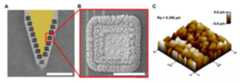
도 2는 실시예의 (1) 단계에서 제조된 전극에 대한 SEM 이미지(도 2의 A), 상기 제조된 전극 상의 Pt black 층을 확대하여 나타낸 SEM 이미지(도 2의 B) 및 상기 Pt black 층의 모폴로지 (도 2의 C)를 나타낸다.
도 3은 평가예 1에 기재된 3종 전극의 이미지 (도 3의 A) 및 이들 3종 전극에 대해 측정한 임피던스 값을 나타내는 그래프 (도 3의 B)이다.
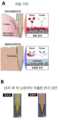
도 4는 SAM 층 및 윤활제층을 형성하지 않은 대조군 및 본 발명에 따른 실시예에서 SAM 층과 윤활제층을 모두 형성한 실험군에서의 생체 내 혈액 및 단백질의 부착 기전 (도 4의 A), 및 이들 대조군의 전극과 실험군의 전극을 쥐의 뇌에 삽입한 후 16주 후 적출한 전극의 표면 상태 이미지 (도 4의 B)를 나타낸다.
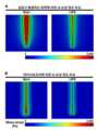
도 5는 Bare 전극 (대조군) 및 LIPS 전극 (본 발명)을 쥐의 뇌에 삽입할 때 발생하는 외력에 의한 뇌 손상 정도 (도 5의 A) 및 마이크로모션에 의한 뇌 손상 정도 (도 5의 B)를 나타낸다.
도 6은 Bare 전극 (대조군) 및 LIPS 전극 (본 발명) 각각을 삽입했을 때 발생하는 생부착력과 마찰력을 비교하기 위해 in vitro 실험을 한 결과를 나타낸다.
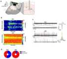
도 7은 Bare 전극 (대조군) 및 LIPS 전극 (본 발명) 각각을 쥐의 뇌에 삽입한 후 60초 동안 실시간 전극 동작능을 비교하는 in vivo 실험 결과를 나타낸다.
도 8은 Bare 전극 (대조군) 및 LIPS 전극 (본 발명, 실험군) 각각을 쥐의 뇌에 삽입한 후 장기간 전극 동작능을 비교하는 in vivo 실험 결과를 나타낸다.
도 9는 Bare 전극 (대조군) 및 LIPS 전극 (본 발명, 실험군) 각각을 쥐의 뇌에 삽입한 후 주변 뇌 조직의 염색 결과를 비교하는 in vivo 실험 결과를 나타낸다.1 exemplarily and schematically shows a method for manufacturing an electrode according to an embodiment of the present invention.
Figure 2 is a SEM image of the electrode prepared in step (1) of the embodiment (FIG. 2A), an enlarged SEM image of the Pt black layer on the prepared electrode (FIG. 2B) and the Pt black layer It shows the morphology (C in Fig. 2).
FIG. 3 is an image of three types of electrodes described in Evaluation Example 1 (FIG. 3A) and a graph showing impedance values measured for these three types of electrodes (FIG. 3B).
Figure 4 shows the adhesion mechanism of blood and protein in vivo in a control group without forming a SAM layer and a lubricant layer and in an experimental group in which both a SAM layer and a lubricant layer were formed in an example according to the present invention (FIG. 4A), and these An image of the surface state of the electrode (Fig. 4B), which was removed 16 weeks after the electrodes of the control group and the experimental group were inserted into the brain of the rat, is shown.
Figure 5 shows the degree of brain damage caused by external force (Fig. 5A) and micro-motion (B in Fig. ).
6 shows the results of an in vitro experiment to compare the bioadhesive force and frictional force generated when each of the bare electrode (control group) and the LIPS electrode (present invention) is inserted.
7 shows in vivo experimental results comparing real-time electrode performance for 60 seconds after each of a bare electrode (control group) and a LIPS electrode (invention) was inserted into the brain of a rat.
8 shows the results of an in vivo experiment comparing long-term electrode operating performance after each of a bare electrode (control group) and a LIPS electrode (the present invention, experimental group) was inserted into the brain of a rat.
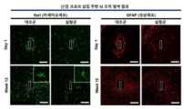
9 shows in vivo experimental results comparing staining results of surrounding brain tissue after each of a bare electrode (control group) and a LIPS electrode (the present invention, experimental group) was inserted into the brain of a rat.
이하, 본 발명에 대해 상세히 설명한다.Hereinafter, the present invention will be described in detail.
본 출원에서 사용한 용어는 단지 특정한 구현예를 설명하기 위해 사용된 것으로서 본 발명을 한정하려는 의도가 아니다. 다르게 정의되지 않는 한, 기술적이거나 과학적인 용어를 포함해서 여기서 사용되는 모든 용어들은 본 발명이 속하는 기술 분야에서 통상의 지식을 가진 자에 의해 일반적으로 이해되는 것과 동일한 의미를 가지고 있다.The terms used in this application are only used to describe specific embodiments and are not intended to limit the present invention. Unless defined otherwise, all terms used herein, including technical or scientific terms, have the same meaning as commonly understood by one of ordinary skill in the art to which the present invention belongs.
명세서 전체에서, 어떤 부분이 어떤 구성요소를 "포함"한다, "함유"한다, "가지다"라고 할 때, 이는 특별히 달리 정의되지 않는 한, 다른 구성 요소를 더 포함할 수 있다는 것을 의미한다.Throughout the specification, when a part “includes,” “includes,” or “has” a certain component, it means that it may further include other components unless otherwise specifically defined.
또한, 첨부 도면을 참조하여 설명함에 있어, 동일한 구성 요소는 동일한 부호를 부여하고 이에 대한 중복되는 설명은 생략하기로 한다. 도면들에 있어서, 예를 들면, 부재들의 크기와 형상은 설명의 편의와 명확성을 위하여 과장될 수 있으며, 실제 구현시, 도시된 형상의 변형들이 예상될 수 있다. 따라서, 본 발명의 실시예는 본 명세서에 도시된 영역의 특정 형상에 제한된 것으로 해석되어서는 아니된다.In addition, in the description with reference to the accompanying drawings, the same components are given the same reference numerals, and overlapping descriptions thereof will be omitted. In the drawings, for example, the size and shape of members may be exaggerated for convenience and clarity of explanation, and deformations of the illustrated shapes may be expected in actual implementation. Accordingly, embodiments of the present invention should not be construed as being limited to the specific shape of the region shown herein.
제1, 제2 등의 용어는 하나의 구성요소를 다른 구성요소로부터 구별하기 위해 사용되는 것으로, 구성요소가 전술한 용어들에 의해 제한되는 것은 아니다.Terms such as first and second are used to distinguish one component from another, and the components are not limited by the aforementioned terms.
층, 막 등의 어떤 부분이 다른 부분 "위에" 또는 "상에" 있다고 할 때, 이는 다른 부분 "바로 위에" 또는 "바로 상에" 있어서 어떤 부분과 다른 부분이 서로 접해 있는 경우 뿐만 아니라 그 중간에 또 다른 부분이 존재하는 경우도 포함한다. 반대로 어떤 부분이 다른 부분 "바로 위에" 또는 "바로 상에" 있다고 할 때는 중간에 다른 부분이 없는 것을 의미한다.When a part of a layer, film, etc., is said to be "on" or "on" another part, it means "directly on" or "directly on" the other part, not only when the part and the other part are in contact with each other, but also in between. Including the case where another part exists in Conversely, when a part is said to be "directly on" or "directly on" another part, it means that there are no intervening parts.
본 발명의 일 양태에 따르면, 생체내 삽입가능한 전극으로서, 기판; 상기 기판 상의 전기 전도층; 상기 전기 전도층 상의 백금흑(platinum black) 층; 상기 백금흑 층 상의 자기조립 단분자(Self-Assembled Monolayer, SAM) 층; 상기 자기조립 단분자 층 상의 윤활제층을 포함하는 전극이 제공된다.According to one aspect of the present invention, there is provided an electrode that can be inserted into a living body, comprising: a substrate; an electrically conductive layer on the substrate; a platinum black layer on the electrically conductive layer; a self-assembled monolayer (SAM) layer on the platinum black layer; An electrode comprising a lubricant layer on the self-assembled monomolecular layer is provided.
상기 기판은 유리(SiO2), 실리콘(Si), 플라스틱 등일 수 있으며, 구체적으로는 플렉서블 기판일 수 있다. 상기 플렉서블 기판의 예로는 PC(polycarbonate), PET(Polyethylene Telephthalate), PEN(Polyethylene Naphthalate), PDMS(polydimethylsiloxane), 에코플렉스(ecoflex), 및 PI(polyimide)를 들 수 있다.The substrate may be glass (SiO2 ), silicon (Si), plastic, or the like, and specifically may be a flexible substrate. Examples of the flexible substrate include polycarbonate (PC), polyethylene telephthalate (PET), polyethylene naphthalate (PEN), polydimethylsiloxane (PDMS), ecoflex, and polyimide (PI).
상기 전기 전도층은 생체 조직으로부터 신호를 수신하거나 신호를 전달하거나, 전기 자극을 제공하는 것일 수 있다. 상기 전기 전도층은 전기 전도성 금속, 구체적으로 금(Au), 은(Ag), 백금(Pt), 구리(Cu), 티타늄(Ti), 텅스텐(W), 및 몰리브덴(Mo)으로 이루어진 군에서 선택되는 1종 또는 2종 이상의 합금을 포함할 수 있다. 또한, 상기 전기 전도층은 서로 상이한 재료의 제1 금속층과 제2 금속층이 서로 적층된 2층 구조일 수 있으며, 예를 들어, 기판과의 접착성 향상을 위해 제1 금속층으로 Ti 와 같은 금속을 증착하고, 그 위에 전술한 전기 전도성 금속을 제2 금속층으로서 증착한 것일 수 있다. 상기 전기 전도층은 증착후 포토레지스트를 이용하여 패터닝한 것일 수 있다. 상기 전기 전도층은 금속 배선부와 금속 팁(tip)부를 포함할 수 있다. 여기서 상기 금속 배선과 금속 팁은 서로 동일하거나 혹은 서로 상이한 물질로 이루어질 수 있으며, 예를 들어, 상기 금속 배선은 Ti/Au 층이고 상기 금속 팁은 Ti/Pt 층일 수 있다. 상기 전기 전도층의 상기 금속 배선 상에는 SiO2 와 같은 절연층이 추가로 형성될 수 있고, 이와 달리, 상기 금속 팁 상에는 절연층이 형성되지 않을 수 있다. 이에 따라 상기 금속 배선은 생체 조직을 향해 노출되지 않고 의료 기기와 금속 팁 사이에 전기적 신호를 전달하는 역할을 하고, 상기 금속 팁은 생체조직을 향해 노출되어 생체조직으로부터 신호를 수신하거나 전기 자극을 제공하는 등의 역할을 하는 것일 수 있다.The electrically conductive layer may receive or transmit signals from living tissue or provide electrical stimulation. The electrically conductive layer is an electrically conductive metal, specifically from the group consisting of gold (Au), silver (Ag), platinum (Pt), copper (Cu), titanium (Ti), tungsten (W), and molybdenum (Mo) One or two or more selected alloys may be included. In addition, the electrically conductive layer may have a two-layer structure in which a first metal layer and a second metal layer of different materials are stacked on each other. For example, a metal such as Ti is used as the first metal layer to improve adhesion with the substrate. deposited, and the above-described electrically conductive metal may be deposited thereon as a second metal layer. The electrical conductive layer may be patterned using a photoresist after deposition. The electrically conductive layer may include a metal wiring part and a metal tip part. Here, the metal wire and the metal tip may be made of the same material or different materials. For example, the metal wire may be a Ti/Au layer and the metal tip may be a Ti/Pt layer. An insulating layer such as SiO2 may be additionally formed on the metal wire of the electrical conductive layer, and, unlike this, no insulating layer may be formed on the metal tip. Accordingly, the metal wiring serves to transmit an electrical signal between the medical device and the metal tip without being exposed toward the living tissue, and the metal tip is exposed toward the living tissue to receive signals from the living tissue or provide electrical stimulation. It may be that it plays a role, etc.
상기 전기 전도층 (또는 상기 전기 전도층의 금속 팁)상에 백금흑(platinum black) 층이 형성된다. 상기 백금흑은 촉매적 특성이 우수한 백금의 미세 분말로서, 흑색을 띄기 때문에 백금흑이라 명명된 것이다. 상기 백금흑 층은 전기도금에 의해 형성될 수 있다.A platinum black layer is formed on the electrically conductive layer (or the metal tip of the electrically conductive layer). The platinum black is a fine powder of platinum having excellent catalytic properties, and is named platinum black because it has a black color. The platinum black layer may be formed by electroplating.
상기 SAM 층의 SAM은 알킬트리클로로실란, 알킬트리메톡시실란, 알킬트리에톡시실란, 폴리테트라플루오로에틸렌(PTFE), 퍼플루오로알콕시 알칸(PFA), 디클로로디메틸실란(DDMS), 퍼플루오로데실트리클로로실란(FDTS), 옥타데실트리메톡시실란(OTMS), 트리클로로(1H,1H,2H,2H-퍼플루오로옥틸)실란(FOTS), 및 트리에톡시(1H,1H,2H,2H-퍼플루오로-1-옥틸)실란(POTS)로 이루어진 군에서 선택되는 1종 이상일 수 있다.The SAM of the SAM layer is alkyltrichlorosilane, alkyltrimethoxysilane, alkyltriethoxysilane, polytetrafluoroethylene (PTFE), perfluoroalkoxy alkane (PFA), dichlorodimethylsilane (DDMS), perfluoro rhodecyltrichlorosilane (FDTS), octadecyltrimethoxysilane (OTMS), trichloro(1H,1H,2H,2H-perfluorooctyl)silane (FOTS), and triethoxy(1H,1H,2H , 2H-perfluoro-1-octyl) silane (POTS) may be one or more selected from the group consisting of.
상기 윤활제층은 전극의 생체내 삽입시 조직과의 마찰을 방지하고 조직 내에 존재하는 생체물질의 부착을 방지하기 위한 물질이며, 퍼플루오로퍼하이드로페난트렌 (Perfluoroperhydrophenanthrene), 퍼플루오로데칼린(Perfluorodecalin), 및 퍼플루오로폴리에테르(perfluoropolyether)로 이루어진 군에서 선택되는 1종 이상일 수 있다. 상기 퍼플루오로폴리에테르로는 크리톡스(Krytox)-100이라고 불리는 것이 포함될 수 있다.The lubricant layer is a material for preventing friction with tissue when inserting an electrode into a living body and preventing adhesion of biological materials present in tissue, and includes perfluoroperhydrophenanthrene, perfluorodecalin, And it may be at least one selected from the group consisting of perfluoropolyether (perfluoropolyether). The perfluoropolyether may include what is called Krytox-100.
본 발명의 다른 일 양태에 따르면, (a) 전기 전도층 상에 백금흑 층을 형성하는 단계; (b) 상기 백금흑 층 상에 자기조립 단분자층을 형성하는 단계; 및 (c) 상기 자기조립 단분자층 상에 윤활제층을 형성하는 단계를 포함하는, 생체내 삽입가능한 전극의 제조 방법이 제공된다.According to another aspect of the present invention, (a) forming a platinum black layer on the electrical conductive layer; (b) forming a self-assembled monolayer on the platinum black layer; and (c) forming a lubricant layer on the self-assembled monolayer.
본 발명의 일 구현예에 따르면, 상기 (a) 단계를 수행하기 전에, (a-1) 기판 상에 전기 전도 물질을 증착하고, 이를 패터닝하여 전기 전도층을 형성하는 단계를 추가로 더 포함할 수 있다. 구체적으로, 기판 상에 제1 전기 전도 물질을 증착하여 패터닝함으로써 금속 배선을 형성하고, 그 후, 제2 전기 전도 물질을 증착하여 패터닝함으로써 금속 팁을 형성할 수 있다. 여기서 상기 금속 배선과 금속 팁이 상기 전기 전도층을 구성할 수 있다. 상기 패터닝은 통상의 포토리소그래피, 전자빔 리소그래피, 또는 리프트-오프 기술에 의해 수행될 수 있다. 또한, 구체적으로, 상기 제1 전기 전도 물질과 상기 제2 전기 전도 물질은 전기 전도성 금속, 구체적으로 금(Au), 은(Ag), 백금(Pt), 구리(Cu), 티타늄(Ti), 텅스텐(W), 및 몰리브덴(Mo)으로 이루어진 군에서 선택되는 1종 또는 2종 이상의 합금을 포함할 수 있다. 상기 제1 전기 전도 물질과 제2 전기 전도 물질은 동일하거나 상이할 수 있다. 예를 들어, 금속 배선을 형성하는 상기 제1 전기 전도 물질은 Ti/Au 층이고 금속 팁을 형성하는 상기 제2 전기 전도 물질은 Ti/Pt 층일 수 있다.According to one embodiment of the present invention, prior to performing the step (a), (a-1) depositing an electrically conductive material on the substrate and patterning it to form an electrically conductive layer may be further included. can Specifically, a metal wire may be formed by depositing and patterning a first electrically conductive material on a substrate, and then a metal tip may be formed by depositing and patterning a second electrically conductive material. Here, the metal wire and the metal tip may constitute the electrical conductive layer. The patterning may be performed by conventional photolithography, electron beam lithography, or lift-off techniques. In addition, specifically, the first electrically conductive material and the second electrically conductive material may include an electrically conductive metal, specifically gold (Au), silver (Ag), platinum (Pt), copper (Cu), titanium (Ti), One or two or more alloys selected from the group consisting of tungsten (W) and molybdenum (Mo) may be included. The first electrically conductive material and the second electrically conductive material may be the same or different. For example, the first electrically conductive material forming the metal wiring may be a Ti/Au layer and the second electrically conductive material forming the metal tip may be a Ti/Pt layer.
또한, 본 발명의 다른 일 구현예에 따르면, 상기 (a) 단계를 수행하기 전에, (a-2) 상기 전기 전도층의 일부 상에 절연층을 형성하는 단계를 더 포함할 수 있다. 상기 절연층은 전기 전도층의 일부가 생체 조직을 향해 노출되어 접촉하지 않도록 하기 위한 것이다. 따라서, 상기 절연층은 전기 전도층의 일부, 구체적으로는 금속 배선 상에 형성된다. 상기 절연층이 그 위에 형성된 전기 전도층, 구체적으로 금속 배선은 생체 조직을 향해 노출되지 않고 전극 내에 위치하여, 생체 조직을 향해 노출된 금속 팁으로부터 수신되는 신호 또는 금속 팁으로 송신되는 신호를 외부 노이즈의 영향 없이 전달하는 역할을 할 수 있다.Further, according to another embodiment of the present invention, before performing step (a), (a-2) forming an insulating layer on a portion of the electrically conductive layer may be further included. The insulating layer is to prevent a part of the electrically conductive layer from being exposed toward and contacting the living tissue. Thus, the insulating layer is formed on a part of the electrically conductive layer, specifically on the metal wiring. The electrically conductive layer on which the insulating layer is formed, specifically, the metal wiring, is located in the electrode without being exposed toward the living tissue, so that the signal received from the metal tip exposed toward the living tissue or the signal transmitted to the metal tip is exposed to external noise. can play a role in transmitting without the influence of
상기 (a) 단계는 전기 전도층 상에 백금흑 층을 형성하는 단계로서, 이는 전기 도금에 의해 실시될 수 있다. 상기 전기 도금은, 구체적으로, 백금흑 입자를 형성할 수 있는 백금 전구체를 용매에 용해시킨 전기도금액을 제조한 후, 전극을 상기 전기도금액에 침지시킨 후 전압을 인가하여 수행될 수 있다. 여기서 상기 백금 전구체로는 플라티늄클로라이드(Platinum chloride), 포타슘테트라클로로플라티네이트(Potassium tetrachloroplatinate), 테트라아민플라티늄 클로라이드(Tetraammineplatinum chloride) 및 클로로백금산 하이드레이트(Chloroplatinic acid hydrate) 등을 사용할 수 있다. 상기 전기도금액은 백금 전구체와 용매 이외에도 납 아세테이트를 추가로 더 함유할 수 있다. 상기 전압 인가 시간에 따라 백금흑 층의 두께가 제어될 수 있으며, 구체적으로는 1 내지 60초 동안 수행될 수 있다. 상기 전기도금은 기준 전극과 작동 전극으로 구성되는 2전극 시스템에 의해 수행되거나 또는 기준 전극, 대응 전극, 및 작동 전극으로 구성되는 3전극 시스템에 의해 수행될 수 있다. 본 발명에 따른 전극을 상기 2전극 또는 3전극 시스템에서 작동 전극으로 사용하여 전기도금에 의해 백금흑 층을 형성할 수 있다.Step (a) is a step of forming a platinum black layer on the electrical conductive layer, which may be performed by electroplating. Specifically, the electroplating may be performed by preparing an electroplating solution in which a platinum precursor capable of forming platinum black particles is dissolved in a solvent, immersing an electrode in the electroplating solution, and then applying a voltage. Platinum chloride, potassium tetrachloroplatinate, tetraammineplatinum chloride, and chloroplatinic acid hydrate may be used as the platinum precursor. The electroplating solution may further contain lead acetate in addition to the platinum precursor and the solvent. The thickness of the platinum black layer may be controlled according to the voltage application time, and specifically, it may be performed for 1 to 60 seconds. The electroplating may be performed by a two-electrode system consisting of a reference electrode and a working electrode, or by a three-electrode system consisting of a reference electrode, a counter electrode, and a working electrode. The electrode according to the present invention can be used as a working electrode in the two-electrode or three-electrode system to form a platinum black layer by electroplating.
본 발명의 일 구현예에 따르면, 본 발명의 방법은 상기 (b) 단계에서 자기조립 단분자층을 형성하기 전에 상기 백금흑 층을 표면처리하는 단계를 더 포함할 수 있다. 상기 표면처리는 상기 백금흑 층을 N2O 또는 O2 플라즈마 처리하는 단계일 수 있다. 여기서 상기 플라즈마 처리는 상압 하에 진행될 수 있다. 이러한 플라즈마 표면처리를 통해 백금흑 층 상에 히드록실 말단기(-OH 기)가 형성될 수 있다. 자기조립 단분자막 중에서 헤드 그룹 부분이 트리클로로실란 그룹을 가지고 있는 것, 예를 들어 FDTS 및 FOTS 이 상기 히드록실기와 공유결합을 형성할 수 있고, 이에 따라 상기 표면 처리에 의해 후속하는 자기조립 단분자층과의 결합이 개선될 수 있게 된다.According to one embodiment of the present invention, the method of the present invention may further include a step of surface treating the platinum black layer before forming the self-assembled monolayer in step (b). The surface treatment may be a step of treating the platinum black layer with N2 O or O2 plasma. Here, the plasma treatment may be performed under atmospheric pressure. Through this plasma surface treatment, a hydroxyl terminal group (—OH group) may be formed on the platinum black layer. Among the self-assembled monolayers, those having a trichlorosilane group in the head group portion, for example, FDTS and FOTS, can form a covalent bond with the hydroxyl group, and therefore, the subsequent self-assembled monolayer and combination can be improved.
상기 (b) 단계는 상기 백금흑 층 상에 자기조립 단분자층을 형성하는 단계이다. 본 단계는 액상법 또는 기상법 중 임의 방법에 의해 수행될 수 있다. 액상법의 경우, 상기 백금흑 층이 형성된 전극을 자기조립 단분자막 형성용 단분자가 함유된 유기 용액 중에 담지시킴으로써 수행될 수 있다. 또한, 상기 기상법은 상기 백금흑 층 상에 자기조립 단분자를 증착시켜 수행될 수 있으며, 상기 증착은 구체적으로는 진공 챔버 내에서, 예를 들어 0.8 내지 1.2 Torr의 챔버 압력 하의 진공 챔버 내에서 수행될 수 있다. 이에, 본 발명의 일 구현예에 따르면, 상기 (b) 단계는 자기조립 단분자막 형성용 단분자가 함유된 용액을 0.8 내지 1.2 Torr의 진공 챔버 내에서 증착시켜 수행될 수 있다.Step (b) is a step of forming a self-assembled monolayer on the platinum black layer. This step may be performed by any method of a liquid phase method or a gas phase method. In the case of the liquid phase method, the electrode on which the platinum black layer is formed may be immersed in an organic solution containing monomolecules for forming a self-assembled monolayer. In addition, the vapor phase method may be performed by depositing self-assembled single molecules on the platinum black layer, and the deposition may be performed in a vacuum chamber, for example, in a vacuum chamber under a chamber pressure of 0.8 to 1.2 Torr. can Therefore, according to one embodiment of the present invention, step (b) may be performed by depositing a solution containing monomolecules for forming a self-assembled monolayer in a vacuum chamber at 0.8 to 1.2 Torr.
상기 (c) 단계는 상기 자기조립 단분자층 상에 윤활제층을 형성하는 단계이다. 상기 윤활제는 점성 및 밀도 수치에 따라 생체 적합성이 뛰어난 액체가 사용될 수 있으며, 그 예로는 퍼플루오로퍼하이드로페난트렌 (Perfluoroperhydrophenanthrene), 퍼플루오로데칼린(Perfluorodecalin), 및 퍼플루오로폴리에테르(perfluoropolyether)를 들 수 있다. 상기 윤활제는 상기 자기조립 단분자층이 형성된 전극을 상기 윤활제층 형성용 윤활제 용액에 담지함으로써 수행될 수 있다. 상기 윤활제는 전극 표면을 습윤화하고 표면 에너지를 낮게 유지할 수 있으며, 이에 따라, 세균, 박테리아 등의 미생물이 표면에 부착되지 못하고 표면에서 미끄러지게 할 수 있다. 본 단계는 상기 자기조립 단분자층이 형성된 전극을 윤활제 용액에 침지함으로써 수행될 수 있다.Step (c) is a step of forming a lubricant layer on the self-assembled monolayer. As the lubricant, a liquid having excellent biocompatibility may be used according to viscosity and density values, and examples thereof include perfluoroperhydrophenanthrene, perfluorodecalin, and perfluoropolyether. can be heard The lubricant may be applied by immersing the electrode on which the self-assembled monolayer is formed in a lubricant solution for forming the lubricant layer. The lubricant can wet the surface of the electrode and keep the surface energy low, and thus, microorganisms such as germs and bacteria can slide on the surface without being attached to the surface. This step may be performed by immersing the electrode on which the self-assembled monolayer is formed in a lubricant solution.
본 발명의 또다른 일 양태에 따르면, 전술한 바와 같은 생체내 삽입가능한 전극을 포함하는 의료기기가 제공된다. 상기 의료기기는 인체에 이식되어 신체 기능의 일부를 대체 보조하거나 인체에 삽입되어 전기적 자극을 전달하는 것일 수 있다. 이와 달리, 상기 의료기기는 반드시 전기적 신호를 전달하는 것으로 한정될 필요는 없으며, 인체에 삽입되어 의약품을 주입하는 의료기기일 수 있다.According to another aspect of the present invention, there is provided a medical device including an electrode that can be inserted into a living body as described above. The medical device may be implanted into the human body to replace and assist part of a body function, or may be inserted into the human body to transmit electrical stimulation. Unlike this, the medical device is not necessarily limited to transmitting an electrical signal, and may be a medical device that is inserted into the human body and injects medicine.
이하, 본 발명의 이해를 돕기 위하여 실시예를 참고하여 본 발명을 보다 상세히 설명한다. 그러나 하기의 실시예는 본 발명을 보다 쉽게 이해하기 위하여 제공되는 것일 뿐, 하기 실시예에 의해 본 발명의 내용이 한정되는 것은 아니다.Hereinafter, the present invention will be described in more detail with reference to examples to aid understanding of the present invention. However, the following examples are provided to more easily understand the present invention, and the content of the present invention is not limited by the following examples.
[실시예] 본 발명에 따른 전극의 제조[Example] Preparation of electrode according to the present invention
신경 신호 기록을 위한 신경 프로브(neural probe)의 Pt 전극 상에 백금흑(Pt black)을 다음과 같이 전기도금하였다. 헥사클로로백금산 하이드레이트(hexachloroplatinic acid hydrate, HCPA), 0.025 N HCl, 및 0.025% 납 아세테이트를 탈이온수 중에 혼합하여 백금흑(Pt black) 전기도금액을 제조하였다. 다음으로, 신경 전극을 백금 와이어 (기준 전극) 및 Ag/AgCl 와이어 (상대 전극)과 함께 상기 전기도금액에 침지하였다. 정전위기(potentiostat) (PalmSens3, PalmSens, Netherlands)를 통해 0.2 V 의 전위를 35 초 동안 인가함으로써 백금흑 전기도금액 중의 백금 입자가 백금 전극 상에 도금되도록 하였다. 이렇게 제조된 전극에 대한 SEM 이미지를 도 2의 A 에 도시하였다. 도 2의 B는 상기 제조된 전극 상의 백금흑(Pt black) 층을 확대하여 나타낸 SEM 이미지이며, 도 2의 C 는 상기 Pt black 층의 모폴로지를 나타내는 것이다.Platinum black was electroplated on the Pt electrode of a neural probe for recording nerve signals as follows. A Pt black electroplating solution was prepared by mixing hexachloroplatinic acid hydrate (HCPA), 0.025 N HCl, and 0.025% lead acetate in deionized water. Next, the neural electrode was immersed in the electroplating solution together with a platinum wire (reference electrode) and an Ag/AgCl wire (counter electrode). Platinum particles in a platinum black electroplating solution were allowed to plate on the platinum electrode by applying a potential of 0.2 V through a potentiostat (PalmSens3, PalmSens, Netherlands) for 35 seconds. A SEM image of the electrode thus prepared is shown in A of FIG. 2 . B of FIG. 2 is an enlarged SEM image of the Pt black layer on the manufactured electrode, and C of FIG. 2 shows the morphology of the Pt black layer.
위와 같이 제조한 프로브를 주변 산소 (100 W, 5 분) 하에서 플라즈마 처리하여 히드록실(-OH) 말단 기가 형성되도록 표면처리한 후, 멀티-밸브 진공 챔버 (1 Torr)로 즉시 옮겼다. 미리 탈기해둔 다른 진공 챔버 (1 Torr)에 트리클로로(1H,1H,2H,2H-퍼플루오로옥틸)실란 (FOTS, Sigma-Aldrich, Germany) 200 μL가 들어있는 유리 바이알을 넣고, 상기 프로브가 들어 있는 멀티-밸브 챔버에 연결시켜서 30분 동안 60℃에서 유지시켰다. 그 후, FOTS 증기를 공급하는 밸브를 잠그고, 증기화된 탈이온수로 충전된 다른 챔버에 상기 멀티-밸브 챔버를 연결하여 수증기가 공급되도록 하였다. 30분 후, 상기 챔버를 단리시키고 1 Torr 까지 탈기하였고, 이 과정을 2회 반복하여 SAM 내의 모든 핀홀이 피복되게 하였다. 다음으로, FOTS SAM이 형성된 프로브를 이소프로필 알코올(IPA) 및 탈이온수로 세정하여 과량의 FOTS 를 제거하였다. 퍼플루오로폴리에테르(PFPE) 윤활제 (Krytox 101, 대부분의 비극성 및 극성 액체와 혼화가능; 화학적으로 안정함; DuPont, USA)를 0.2 μm 필터를 통해 여과한 후, 상기 프로브를 상기 윤활제에 침지하여 윤활제층을 형성시켰다. 과량의 윤활제는 프로브를 24 시간 동안 90°로 기울여서 제거하였고, 그 후, 프로브를 수술에 바로 사용하였다.The probe prepared as described above was plasma-treated under ambient oxygen (100 W, 5 minutes) to form hydroxyl (-OH) end groups, and then immediately transferred to a multi-valve vacuum chamber (1 Torr). A glass vial containing 200 μL of trichloro(1H,1H,2H,2H-perfluorooctyl)silane (FOTS, Sigma-Aldrich, Germany) was placed in another previously degassed vacuum chamber (1 Torr), and the probe It was connected to an enclosed multi-valve chamber and maintained at 60° C. for 30 minutes. After that, the valve for supplying FOTS steam was closed, and the multi-valve chamber was connected to another chamber filled with vaporized deionized water to supply steam. After 30 minutes, the chamber was isolated and degassed to 1 Torr, and this process was repeated twice to ensure that all pinholes in the SAM were covered. Next, the probe on which the FOTS SAM was formed was washed with isopropyl alcohol (IPA) and deionized water to remove excess FOTS. After filtering a perfluoropolyether (PFPE) lubricant (Krytox 101, miscible with most non-polar and polar liquids; chemically stable; DuPont, USA) through a 0.2 μm filter, the probe is immersed in the lubricant A lubricant layer was formed. Excess lubricant was removed by tilting the probe at 90° for 24 hours, after which the probe was used directly for surgery.
[평가예 1] 임피던스 측정[Evaluation Example 1] Impedance measurement
Pt black 층, SAM 층 및 윤활제층을 형성하지 않은 것을 제외하고는 상기 실시예에서와 동일한 방식으로 제조한 Bare 전극 (이하, Bare (w/o Pt black) 으로도 표시함), Pt black 층만 형성하고 SAM 층 및 윤활제층을 형성하지 않은 것을 제외하고는 상기 실시예에서와 동일한 방식으로 제조한 Bare 전극 (이하, Bare (w/ Pt black)으로도 표시함), 및 상기 실시예에 따라 Pt black 층, SAM 층, 및 윤활제층을 모두 형성한 본 발명에 따른 전극 (이하, LIPS 전극으로도 표시함) 각각에 대한 이미지를 도 3의 A 에 나타내었다. 이들 3종의 전극에 대해 임피던스를 측정하였고 그 결과를 도 3의 B 에 나타내었다. 도 3의 B 로부터 Pt black 을 사용함으로써 임피던스 값이 감소할 수 있다는 것을 알 수 있다.Except for not forming a Pt black layer, a SAM layer, and a lubricant layer, only a bare electrode (hereinafter also referred to as a bare (w/o Pt black)) and a Pt black layer manufactured in the same manner as in the above embodiment was formed. Bare electrode (hereinafter also referred to as Bare (w/ Pt black)) manufactured in the same manner as in the above embodiment except that the SAM layer and the lubricant layer were not formed, and Pt black according to the above embodiment An image of each electrode (hereinafter, also referred to as a LIPS electrode) according to the present invention in which all layers, a SAM layer, and a lubricant layer are formed is shown in A of FIG. 3 . Impedance was measured for these three types of electrodes, and the results are shown in B of FIG. 3 . It can be seen from B of FIG. 3 that the impedance value can be reduced by using Pt black.
[평가예 2] 생부착 방지 효과[Evaluation Example 2] Bioadhesion prevention effect
SAM 층 및 윤활제층을 형성하지 않은 대조군 및 본 발명에 따른 실시예에서 SAM 층과 윤활제층을 모두 형성한 실험군을 사용하여, 이들 대조군과 실험군에서의 생체 내 혈액 및 단백질의 부착 기전 및 이들 대조군의 전극과 실험군의 전극을 쥐의 뇌에 삽입한 후 16주 후 적출한 전극의 표면 상태 이미지를 도 4에 나타내었다. 도 4로부터 본 발명에 따라 SAM 층과 윤활제층을 형성시킴으로써 생체내 생부착을 방지할 수 있고, 이에 따라 쥐 뇌로의 삽입 16주가 지난 후 대조군에서는 오염이 발생하였으나 실험군에서는 오염이 발생하지 않음을 확인할 수 있었다.Using the control group in which the SAM layer and the lubricant layer were not formed and the experimental group in which both the SAM layer and the lubricant layer were formed in the examples according to the present invention, the adhesion mechanism of blood and protein in vivo in the control group and the experimental group and the
[평가예 3] 전극 삽입시 외력 또는 마이크로모션에 의한 외상[Evaluation Example 3] Trauma due to external force or micro-motion when electrode is inserted
Bare 전극 (대조군) 및 LIPS 전극 (본 발명) 각각을 쥐의 뇌에 삽입하였고 이 때 발생하는 외력에 의한 뇌 손상 정도 및 삽입후 마이크로모션에 의한 뇌 손상 정도를 시뮬레이션에 의해 비교하였으며 그 결과를 도 5에 나타내었다. 도 5로부터 본 발명에 따른 LIPS 전극을 사용하였을 때 외상 정도가 현저히 감소하였음을 알 수 있다.Each of the bare electrode (control group) and the LIPS electrode (invention) was inserted into the brain of a rat, and the degree of brain damage caused by external force and the degree of brain damage caused by micro-motion after insertion were compared by simulation. 5. It can be seen from FIG. 5 that the degree of trauma was significantly reduced when the LIPS electrode according to the present invention was used.
[평가예 4] 생부착력 및 전극 삽입시의 마찰력을 비교하기 위한 in vitro 실험[Evaluation Example 4] In vitro experiment for comparing bioadhesive force and frictional force during electrode insertion
먼저, 혈액에 BARE 전극(대조군) 및 LIPS 전극 (본 발명, 실험군)을 담궈둔 뒤 혈액 단백질이 전극 표면에 부착함에 따라 증가하는 임피던스를 비교하였다. 그 결과를 도 6의 A 에 나타내었다. 도 6의 A로부터, 대조군의 경우에는 시간이 경과함에 따라 임피던스가 증가하는 것을 알 수 있고, 이는 시간의 경과에 따라 혈액 단백질이 대조군 전극 표면에 점차적으로 부착한다는 것을 의미한다.First, after immersing the BARE electrode (control group) and the LIPS electrode (the present invention, experimental group) in blood, the impedance that increases as blood proteins adhere to the electrode surface was compared. The results are shown in A of FIG. 6 . From A of FIG. 6 , in the case of the control group, it can be seen that the impedance increases over time, which means that blood proteins gradually adhere to the control electrode surface over time.
다음으로, 뇌와 비슷한 물성을 가지는 아가로스 겔(agarose gel)을 만들고, BARE 전극(대조군) 및 LIPS 전극 (본 발명, 실험군) 각각을 일정한 속도 (0.1 mm/s)로 삽입하면서 겔과 전극 간의 마찰을 측정하였다. 삽입 거리에 따른 마찰력을 도 6의 B 에 나타내었다. 또한, 본 실험에서 발생한 마찰력을 충격량으로 정량화하고 그 데이터를 도 6의 C에 나타내었다. 도 6의 B와 C로부터 대조군 전극의 경우에는 삽입에 따른 마찰력이 현저히 더 크게 발생한다는 것을 알 수 있다.Next, an agarose gel having physical properties similar to that of the brain is made, and BARE electrodes (control group) and LIPS electrodes (the present invention, experimental group) are inserted at a constant speed (0.1 mm/s), respectively, between the gel and the electrodes. Friction was measured. The frictional force according to the insertion distance is shown in B of FIG. In addition, the frictional force generated in this experiment was quantified as an impact amount, and the data is shown in FIG. 6C. From B and C of FIG. 6 , it can be seen that in the case of the control electrode, the frictional force according to the insertion is significantly greater.
[평가예 5] 전극 삽입시의 급성 외상 억제능을 비교하기 위한 in vitro 실험[Evaluation Example 5] In vitro experiment for comparing the ability to inhibit acute trauma upon electrode insertion
Bare 전극 (대조군) 및 LIPS 전극 (본 발명) 각각을 쥐의 뇌에 삽입한 후 60초 동안 전기적 신호를 검출하고 이를 기록함으로써 두 전극의 전극 동작능을 비교하였고, 그 실험 개략도 및 결과를 도 7에 나타내었다. 도 7로부터 본 발명에 따른 전극을 사용하였을 때 전기적 신호가 보다 높은 품질로 잘 검출되었다는 것을 알 수 있다 (도 7의 B, C). 또한, 도 7 의 D 로부터 전기 신호의 기록률 (91%)이 대조군 (45%)에 비해 현저히 높았다는 것을 알 수 있다. 이는 본 발명에 따른 전극은 삽입시 급성 외상을 충분히 잘 억제할 수 있어서 주변 세포로부터의 전기적 신호가 급성 외상에 따른 염증 등에 의해 차단되지 않고 잘 검출된다는 것을 의미한다.After inserting each of the bare electrode (control group) and the LIPS electrode (invention) into the brain of the rat, the electrode operational performance of the two electrodes was compared by detecting and recording electrical signals for 60 seconds, and the experimental schematic and results are shown in FIG. 7 shown in It can be seen from FIG. 7 that electrical signals were well detected with higher quality when using the electrode according to the present invention (FIG. 7B and C). In addition, it can be seen from D of FIG. 7 that the electrical signal recording rate (91%) was significantly higher than that of the control group (45%). This means that the electrode according to the present invention can suppress acute trauma sufficiently well when inserted, so that electrical signals from surrounding cells are well detected without being blocked by inflammation or the like caused by acute trauma.
[평가예 6] 전극 삽입시의 면역 거부 반응 억제능을 비교하기 위한 in vivo 실험[Evaluation Example 6] In vivo experiment for comparing immune rejection suppression ability when electrode is inserted
Bare 전극 (대조군) 및 LIPS 전극 (본 발명, 실험군) 각각을 쥐의 뇌에 삽입한 후 전기적 신호가 검출되지 않을 때까지 소요된 시간을 비교해 보았으며 그 결과를 도 8에 나타내었다. 도 8로부터 대조군의 경우 8주만에 전기적 신호 검출이 중단되었는데 반해, 본 발명에 따른 실험군의 경우에는 16주까지 전기적 신호를 검출할 수 있었다는 것을 알 수 있다. 이는 장기간 사용에 따른 생체 내 면역 거부 반응을 본 발명에 따른 실험군에서 억제할 수 있었다는 것을 의미한다.After inserting each of the bare electrode (control group) and the LIPS electrode (the present invention, experimental group) into the brain of the rat, the time required until no electrical signal was detected was compared, and the results are shown in FIG. 8 . It can be seen from FIG. 8 that the detection of electrical signals was stopped after 8 weeks in the control group, whereas the electrical signals were detected up to 16 weeks in the experimental group according to the present invention. This means that the in vivo immune rejection response following long-term use could be suppressed in the experimental group according to the present invention.
[평가예 7] 전극 삽입시의 면역 거부 반응 억제능을 비교하기 위한 in vivo 실험[Evaluation Example 7] In vivo experiment for comparing immune rejection suppression ability when electrode is inserted
Bare 전극 (대조군) 및 LIPS 전극 (본 발명, 실험군) 각각을 쥐의 뇌에 삽입한 후 1일째 및 12주째 되는 날에 쥐의 뇌를 적출하여 주변 뇌 조직 세포(미세아교세포, 성상세포)를 염색하였으며 그 결과를 도 9에 나타내었다. 도 9로부터 대조군에서는 면역 세포의 부착과 증식으로 인해 많은 형광점이 나타난 반면, 본 발명에 따른 실험군에서 이러한 형광점의 수가 대조군에 비해 현저히 적었으며, 이는 본 발명에 따른 전극을 사용함으로써 면역 거부 반응이 억제된다는 것을 알 수 있다.Bare electrodes (control group) and LIPS electrodes (invention, experimental group) were inserted into the brains of rats, respectively, on the 1st and 12th week, and the brains were removed to extract surrounding brain tissue cells (microglia, astrocytes). It was stained and the results are shown in FIG. 9 . 9, while many fluorescent dots appeared due to the attachment and proliferation of immune cells in the control group, the number of fluorescent dots in the experimental group according to the present invention was significantly smaller than that of the control group, indicating that the immune rejection reaction was suppressed by using the electrode according to the present invention. It can be seen that suppression
상기에서는 본 발명의 바람직한 실시예를 참조하여 설명하였지만, 해당 기술 분야의 숙련된 당업자는 하기의 특허 청구 범위에 기재된 본 발명의 사상 및 영역으로부터 벗어나지 않는 범위 내에서 본 발명을 다양하게 수정 및 변경시킬 수 있음을 이해할 수 있을 것이다.Although the above has been described with reference to preferred embodiments of the present invention, those skilled in the art can variously modify and change the present invention without departing from the spirit and scope of the present invention described in the claims below. You will understand that you can.
Claims (10)
Translated fromKorean기판;
상기 기판 상의 전기 전도층;
상기 전기 전도층 상의 백금흑(platinum black) 층;
상기 백금흑 층 상의 자기조립 단분자(Self-Assembled Monolayer, SAM) 층; 및
상기 자기조립 단분자 층 상의 윤활제층을 포함하는 전극.As an implantable electrode in vivo,
Board;
an electrically conductive layer on the substrate;
a platinum black layer on the electrically conductive layer;
a self-assembled monolayer (SAM) layer on the platinum black layer; and
An electrode comprising a lubricant layer on the self-assembled monomolecular layer.
(b) 상기 백금흑 층 상에 자기조립 단분자층을 형성하는 단계; 및
(c) 상기 자기조립 단분자층 상에 윤활제층을 형성하는 단계를 포함하는,
생체내 삽입가능한 전극의 제조 방법.(a) forming a platinum black layer on the electrically conductive layer;
(b) forming a self-assembled monolayer on the platinum black layer; and
(c) forming a lubricant layer on the self-assembled monolayer,
A method for manufacturing an implantable electrode in vivo.
Priority Applications (2)
| Application Number | Priority Date | Filing Date | Title |
|---|---|---|---|
| KR1020210049112AKR102531924B1 (en) | 2021-04-15 | 2021-04-15 | Implantable Electrode and Method for Preparing the Same |
| US17/721,981US20220330871A1 (en) | 2021-04-15 | 2022-04-15 | In vivo insertable electrode and method of manufacturing the same |
Applications Claiming Priority (1)
| Application Number | Priority Date | Filing Date | Title |
|---|---|---|---|
| KR1020210049112AKR102531924B1 (en) | 2021-04-15 | 2021-04-15 | Implantable Electrode and Method for Preparing the Same |
Publications (2)
| Publication Number | Publication Date |
|---|---|
| KR20220142721A KR20220142721A (en) | 2022-10-24 |
| KR102531924B1true KR102531924B1 (en) | 2023-05-12 |
Family
ID=83602904
Family Applications (1)
| Application Number | Title | Priority Date | Filing Date |
|---|---|---|---|
| KR1020210049112AActiveKR102531924B1 (en) | 2021-04-15 | 2021-04-15 | Implantable Electrode and Method for Preparing the Same |
Country Status (2)
| Country | Link |
|---|---|
| US (1) | US20220330871A1 (en) |
| KR (1) | KR102531924B1 (en) |
Families Citing this family (1)
| Publication number | Priority date | Publication date | Assignee | Title |
|---|---|---|---|---|
| KR102710785B1 (en)* | 2024-03-13 | 2024-09-26 | 주식회사 링크솔루텍 | Coating composition for protection of endoscope |
Citations (3)
| Publication number | Priority date | Publication date | Assignee | Title |
|---|---|---|---|---|
| US20110178587A1 (en) | 2008-07-10 | 2011-07-21 | John Chambers | Cochlear implant with modified intracochlear electrode member |
| US8532733B2 (en) | 2006-10-31 | 2013-09-10 | Medtronic, Inc. | Mapping guidelet |
| KR101566342B1 (en) | 2013-11-14 | 2015-11-05 | 한국과학기술원 | Platinum black microelectrode improving mechanical stability and preparation methods thereof |
Family Cites Families (4)
| Publication number | Priority date | Publication date | Assignee | Title |
|---|---|---|---|---|
| WO2013012465A1 (en)* | 2011-07-18 | 2013-01-24 | Thomas Jerome Bachinski | Electrodes, electrode systems, and methods of manufacture |
| US9113929B2 (en)* | 2012-04-19 | 2015-08-25 | St. Jude Medical, Cardiology Division, Inc. | Non-electric field renal denervation electrode |
| TW201350994A (en) | 2012-06-08 | 2013-12-16 | Unity Opto Technology Co Ltd | High-contrast direct type backlight module |
| CN105358070B (en)* | 2013-02-08 | 2018-03-23 | 阿库图森医疗有限公司 | Expandable catheter assembly with flexible printed circuit board |
- 2021
- 2021-04-15KRKR1020210049112Apatent/KR102531924B1/enactiveActive
- 2022
- 2022-04-15USUS17/721,981patent/US20220330871A1/enactivePending
Patent Citations (3)
| Publication number | Priority date | Publication date | Assignee | Title |
|---|---|---|---|---|
| US8532733B2 (en) | 2006-10-31 | 2013-09-10 | Medtronic, Inc. | Mapping guidelet |
| US20110178587A1 (en) | 2008-07-10 | 2011-07-21 | John Chambers | Cochlear implant with modified intracochlear electrode member |
| KR101566342B1 (en) | 2013-11-14 | 2015-11-05 | 한국과학기술원 | Platinum black microelectrode improving mechanical stability and preparation methods thereof |
Also Published As
| Publication number | Publication date |
|---|---|
| KR20220142721A (en) | 2022-10-24 |
| US20220330871A1 (en) | 2022-10-20 |
Similar Documents
| Publication | Publication Date | Title |
|---|---|---|
| Lee et al. | A Personalized Electronic Tattoo for Healthcare Realized by On‐the‐Spot Assembly of an Intrinsically Conductive and Durable Liquid‐Metal Composite | |
| Sunwoo et al. | Advances in soft bioelectronics for brain research and clinical neuroengineering | |
| JP7114289B2 (en) | Zwitterionic surface modification for continuous sensors | |
| Boehler et al. | Long-term stable adhesion for conducting polymers in biomedical applications: IrOx and nanostructured platinum solve the chronic challenge | |
| Decataldo et al. | Stretchable low impedance electrodes for bioelectronic recording from small peripheral nerves | |
| David-Pur et al. | All-carbon-nanotube flexible multi-electrode array for neuronal recording and stimulation | |
| Cointe et al. | Scalable batch fabrication of ultrathin flexible neural probes using a bioresorbable silk layer | |
| EP2747650B1 (en) | Polymer membranes for continuous analyte sensors | |
| Hsu et al. | Encapsulation of an integrated neural interface device with Parylene C | |
| Castagnola et al. | Smaller, softer, lower-impedance electrodes for human neuroprosthesis: a pragmatic approach | |
| Ashok et al. | Flexible nanoarchitectonics for biosensing and physiological monitoring applications | |
| Hara et al. | Long-term stability of intracortical recordings using perforated and arrayed Parylene sheath electrodes | |
| US20060173263A1 (en) | Neural interface assembly and method for making and implanting the same | |
| US20160331326A1 (en) | Flexible neural strip electrodes, flexible neural ribbon electrodes and compartment based embedded nerve tissue electrode interfaces for peripheral nerves | |
| Vafaiee et al. | Gold-plated electrode with high scratch strength for electrophysiological recordings | |
| Kim et al. | Electrochemical co-deposition of polydopamine/hyaluronic acid for anti-biofouling bioelectrodes | |
| CN114778628B (en) | Flexible working electrode and enzyme sensor | |
| Scholten et al. | A 512-channel multi-layer polymer-based neural probe array | |
| CN112545523A (en) | Liquid metal nerve electrode with adjustable hardness and preparation method and application thereof | |
| KR102531924B1 (en) | Implantable Electrode and Method for Preparing the Same | |
| Yang et al. | Liquid-like polymer coating as a promising candidate for reducing electrode contamination and noise in complex biofluids | |
| Seufert et al. | Stretchable Tissue‐Like Gold Nanowire Composites with Long‐Term Stability for Neural Interfaces | |
| US20250152058A1 (en) | Immunosuppressant releasing coatings | |
| CN104535627A (en) | Glucose sensing system | |
| Kim et al. | Soft Cardiac Patch Using a Bifacial Architecture of Adhesive/Low‐Impedance Hydrogel Nanocomposites and Highly Conductive Elastomer Nanocomposites |
Legal Events
| Date | Code | Title | Description |
|---|---|---|---|
| PA0109 | Patent application | Patent event code:PA01091R01D Comment text:Patent Application Patent event date:20210415 | |
| PA0201 | Request for examination | ||
| PG1501 | Laying open of application | ||
| E902 | Notification of reason for refusal | ||
| PE0902 | Notice of grounds for rejection | Comment text:Notification of reason for refusal Patent event date:20221123 Patent event code:PE09021S01D | |
| E701 | Decision to grant or registration of patent right | ||
| PE0701 | Decision of registration | Patent event code:PE07011S01D Comment text:Decision to Grant Registration Patent event date:20230503 | |
| GRNT | Written decision to grant | ||
| PR0701 | Registration of establishment | Comment text:Registration of Establishment Patent event date:20230509 Patent event code:PR07011E01D | |
| PR1002 | Payment of registration fee | Payment date:20230509 End annual number:3 Start annual number:1 | |
| PG1601 | Publication of registration |