KR102530535B1 - Cameras with panoramic scanning range - Google Patents
Cameras with panoramic scanning rangeDownload PDFInfo
- Publication number
- KR102530535B1 KR102530535B1KR1020197026800AKR20197026800AKR102530535B1KR 102530535 B1KR102530535 B1KR 102530535B1KR 1020197026800 AKR1020197026800 AKR 1020197026800AKR 20197026800 AKR20197026800 AKR 20197026800AKR 102530535 B1KR102530535 B1KR 102530535B1
- Authority
- KR
- South Korea
- Prior art keywords
- lens
- delete delete
- camera
- optical path
- panoramic
- Prior art date
- Legal status (The legal status is an assumption and is not a legal conclusion. Google has not performed a legal analysis and makes no representation as to the accuracy of the status listed.)
- Active
Links
Images


Classifications
- G—PHYSICS
- G03—PHOTOGRAPHY; CINEMATOGRAPHY; ANALOGOUS TECHNIQUES USING WAVES OTHER THAN OPTICAL WAVES; ELECTROGRAPHY; HOLOGRAPHY
- G03B—APPARATUS OR ARRANGEMENTS FOR TAKING PHOTOGRAPHS OR FOR PROJECTING OR VIEWING THEM; APPARATUS OR ARRANGEMENTS EMPLOYING ANALOGOUS TECHNIQUES USING WAVES OTHER THAN OPTICAL WAVES; ACCESSORIES THEREFOR
- G03B37/00—Panoramic or wide-screen photography; Photographing extended surfaces, e.g. for surveying; Photographing internal surfaces, e.g. of pipe
- G03B37/02—Panoramic or wide-screen photography; Photographing extended surfaces, e.g. for surveying; Photographing internal surfaces, e.g. of pipe with scanning movement of lens or cameras
- G—PHYSICS
- G02—OPTICS
- G02B—OPTICAL ELEMENTS, SYSTEMS OR APPARATUS
- G02B13/00—Optical objectives specially designed for the purposes specified below
- G02B13/001—Miniaturised objectives for electronic devices, e.g. portable telephones, webcams, PDAs, small digital cameras
- G02B13/0055—Miniaturised objectives for electronic devices, e.g. portable telephones, webcams, PDAs, small digital cameras employing a special optical element
- G02B13/0065—Miniaturised objectives for electronic devices, e.g. portable telephones, webcams, PDAs, small digital cameras employing a special optical element having a beam-folding prism or mirror
- G—PHYSICS
- G02—OPTICS
- G02B—OPTICAL ELEMENTS, SYSTEMS OR APPARATUS
- G02B13/00—Optical objectives specially designed for the purposes specified below
- G02B13/06—Panoramic objectives; So-called "sky lenses" including panoramic objectives having reflecting surfaces
- G—PHYSICS
- G02—OPTICS
- G02B—OPTICAL ELEMENTS, SYSTEMS OR APPARATUS
- G02B27/00—Optical systems or apparatus not provided for by any of the groups G02B1/00 - G02B26/00, G02B30/00
- G02B27/64—Imaging systems using optical elements for stabilisation of the lateral and angular position of the image
- G02B27/642—Optical derotators, i.e. systems for compensating for image rotation, e.g. using rotating prisms, mirrors
- G—PHYSICS
- G02—OPTICS
- G02B—OPTICAL ELEMENTS, SYSTEMS OR APPARATUS
- G02B27/00—Optical systems or apparatus not provided for by any of the groups G02B1/00 - G02B26/00, G02B30/00
- G02B27/64—Imaging systems using optical elements for stabilisation of the lateral and angular position of the image
- G02B27/644—Imaging systems using optical elements for stabilisation of the lateral and angular position of the image compensating for large deviations, e.g. maintaining a fixed line of sight while a vehicle on which the system is mounted changes course
- G—PHYSICS
- G03—PHOTOGRAPHY; CINEMATOGRAPHY; ANALOGOUS TECHNIQUES USING WAVES OTHER THAN OPTICAL WAVES; ELECTROGRAPHY; HOLOGRAPHY
- G03B—APPARATUS OR ARRANGEMENTS FOR TAKING PHOTOGRAPHS OR FOR PROJECTING OR VIEWING THEM; APPARATUS OR ARRANGEMENTS EMPLOYING ANALOGOUS TECHNIQUES USING WAVES OTHER THAN OPTICAL WAVES; ACCESSORIES THEREFOR
- G03B15/00—Special procedures for taking photographs; Apparatus therefor
- G03B15/006—Apparatus mounted on flying objects
- G—PHYSICS
- G03—PHOTOGRAPHY; CINEMATOGRAPHY; ANALOGOUS TECHNIQUES USING WAVES OTHER THAN OPTICAL WAVES; ELECTROGRAPHY; HOLOGRAPHY
- G03B—APPARATUS OR ARRANGEMENTS FOR TAKING PHOTOGRAPHS OR FOR PROJECTING OR VIEWING THEM; APPARATUS OR ARRANGEMENTS EMPLOYING ANALOGOUS TECHNIQUES USING WAVES OTHER THAN OPTICAL WAVES; ACCESSORIES THEREFOR
- G03B17/00—Details of cameras or camera bodies; Accessories therefor
- G03B17/02—Bodies
- G03B17/17—Bodies with reflectors arranged in beam forming the photographic image, e.g. for reducing dimensions of camera
- G—PHYSICS
- G03—PHOTOGRAPHY; CINEMATOGRAPHY; ANALOGOUS TECHNIQUES USING WAVES OTHER THAN OPTICAL WAVES; ELECTROGRAPHY; HOLOGRAPHY
- G03B—APPARATUS OR ARRANGEMENTS FOR TAKING PHOTOGRAPHS OR FOR PROJECTING OR VIEWING THEM; APPARATUS OR ARRANGEMENTS EMPLOYING ANALOGOUS TECHNIQUES USING WAVES OTHER THAN OPTICAL WAVES; ACCESSORIES THEREFOR
- G03B30/00—Camera modules comprising integrated lens units and imaging units, specially adapted for being embedded in other devices, e.g. mobile phones or vehicles
- H—ELECTRICITY
- H04—ELECTRIC COMMUNICATION TECHNIQUE
- H04N—PICTORIAL COMMUNICATION, e.g. TELEVISION
- H04N23/00—Cameras or camera modules comprising electronic image sensors; Control thereof
- H04N23/50—Constructional details
- H04N23/54—Mounting of pick-up tubes, electronic image sensors, deviation or focusing coils
- H—ELECTRICITY
- H04—ELECTRIC COMMUNICATION TECHNIQUE
- H04N—PICTORIAL COMMUNICATION, e.g. TELEVISION
- H04N23/00—Cameras or camera modules comprising electronic image sensors; Control thereof
- H04N23/50—Constructional details
- H04N23/55—Optical parts specially adapted for electronic image sensors; Mounting thereof
- H—ELECTRICITY
- H04—ELECTRIC COMMUNICATION TECHNIQUE
- H04N—PICTORIAL COMMUNICATION, e.g. TELEVISION
- H04N23/00—Cameras or camera modules comprising electronic image sensors; Control thereof
- H04N23/60—Control of cameras or camera modules
- H04N23/69—Control of means for changing angle of the field of view, e.g. optical zoom objectives or electronic zooming
- H—ELECTRICITY
- H04—ELECTRIC COMMUNICATION TECHNIQUE
- H04N—PICTORIAL COMMUNICATION, e.g. TELEVISION
- H04N23/00—Cameras or camera modules comprising electronic image sensors; Control thereof
- H04N23/60—Control of cameras or camera modules
- H04N23/698—Control of cameras or camera modules for achieving an enlarged field of view, e.g. panoramic image capture
- H—ELECTRICITY
- H04—ELECTRIC COMMUNICATION TECHNIQUE
- H04N—PICTORIAL COMMUNICATION, e.g. TELEVISION
- H04N5/00—Details of television systems
- H04N5/222—Studio circuitry; Studio devices; Studio equipment
- H04N5/262—Studio circuits, e.g. for mixing, switching-over, change of character of image, other special effects ; Cameras specially adapted for the electronic generation of special effects
- H04N5/2628—Alteration of picture size, shape, position or orientation, e.g. zooming, rotation, rolling, perspective, translation
- G—PHYSICS
- G03—PHOTOGRAPHY; CINEMATOGRAPHY; ANALOGOUS TECHNIQUES USING WAVES OTHER THAN OPTICAL WAVES; ELECTROGRAPHY; HOLOGRAPHY
- G03B—APPARATUS OR ARRANGEMENTS FOR TAKING PHOTOGRAPHS OR FOR PROJECTING OR VIEWING THEM; APPARATUS OR ARRANGEMENTS EMPLOYING ANALOGOUS TECHNIQUES USING WAVES OTHER THAN OPTICAL WAVES; ACCESSORIES THEREFOR
- G03B2205/00—Adjustment of optical system relative to image or object surface other than for focusing
- G03B2205/0053—Driving means for the movement of one or more optical element
- G03B2205/0069—Driving means for the movement of one or more optical element using electromagnetic actuators, e.g. voice coils
- G—PHYSICS
- G06—COMPUTING OR CALCULATING; COUNTING
- G06T—IMAGE DATA PROCESSING OR GENERATION, IN GENERAL
- G06T7/00—Image analysis
- G06T7/20—Analysis of motion
- G06T7/292—Multi-camera tracking
- H—ELECTRICITY
- H04—ELECTRIC COMMUNICATION TECHNIQUE
- H04N—PICTORIAL COMMUNICATION, e.g. TELEVISION
- H04N23/00—Cameras or camera modules comprising electronic image sensors; Control thereof
- H04N23/45—Cameras or camera modules comprising electronic image sensors; Control thereof for generating image signals from two or more image sensors being of different type or operating in different modes, e.g. with a CMOS sensor for moving images in combination with a charge-coupled device [CCD] for still images
- H—ELECTRICITY
- H04—ELECTRIC COMMUNICATION TECHNIQUE
- H04N—PICTORIAL COMMUNICATION, e.g. TELEVISION
- H04N23/00—Cameras or camera modules comprising electronic image sensors; Control thereof
- H04N23/58—Means for changing the camera field of view without moving the camera body, e.g. nutating or panning of optics or image sensors
Landscapes
- Physics & Mathematics (AREA)
- General Physics & Mathematics (AREA)
- Engineering & Computer Science (AREA)
- Multimedia (AREA)
- Signal Processing (AREA)
- Optics & Photonics (AREA)
- Studio Devices (AREA)
- Stereoscopic And Panoramic Photography (AREA)
- Lens Barrels (AREA)
Abstract
Translated fromKoreanDescription
Translated fromKorean관련 출원에 대한 상호 참조CROSS REFERENCES TO RELATED APPLICATIONS
본 출원은 2017 년 3 월 15 일에 출원된 미국 가특허 출원 제 62/471,662 호 및 2017 년 9 월 20 일에 출원된 미국 가특허 출원 제 62/560,684의 우선권 이익을 주장하며, 이들 모두는 본원에 전체적으로 참고로 포함된다.This application claims the benefit of priority from U.S. Provisional Patent Application Serial No. 62/471,662, filed March 15, 2017, and U.S. Provisional Patent Application Serial No. 62/560,684, filed September 20, 2017, both of which are incorporated herein by reference. is incorporated by reference in its entirety.
본 명세서에 개시된 실시 예는 일반적으로 카메라에 관한 것으로서, 특히 폴디드 광학 기기를 갖는 디지털 카메라에 기초한 카메라에 관한 것이다.Embodiments disclosed herein relate generally to cameras, and more particularly to cameras based on digital cameras with folded optics.
"폴디드 카메라" 또는 "폴디드 카메라 모듈"이라 지칭되는 폴디드 광학 기기를 가진 컴팩트 디지털 카메라가 예컨대 출원인 공동 소유의 국제 특허 출원 PCT/IB2016/052179에 공지되어 있다. 이러한 폴디드 카메라는 렌즈, 광학 경로 폴딩 요소(OPFE)(일반적으로 프리즘 또는 미러) 및 이미지 센서를 포함한다. OPFE는 객체 또는 장면으로부터 OPFE까지의 제 1 축을 따르는 제 1 광학 경로를, 상기 제 1 축에 실질적으로 수직이며 폴디드 카메라의 렌즈 광축인 제 2 축을 따르는 제 2 광학 경로로 폴딩한다. 일부 OPFE는 제 1 축을 중심으로 또는 제 1 축과 제 2 축 모두에 직교하는 제 3 축을 중심으로 틸트하거나 회전하도록 설계된다. OPFE가 렌즈의 광축을 중심으로 회전하는 폴디드 카메라는 전혀 공지되어 있지 않다. 180도 이상의 파노라마 스캐닝이 가능한 폴디드 디지털 카메라를 기반으로 하는 어떠한 카메라도 또한 전혀 공지된 바 없다.A compact digital camera with folded optics, referred to as a "folded camera" or "folded camera module", is known, for example, from Applicant's co-owned international patent application PCT/IB2016/052179. Such a folded camera includes a lens, an optical path folding element (OPFE) (usually a prism or mirror) and an image sensor. The OPFE folds a first optical path along a first axis from the object or scene to the OPFE into a second optical path substantially perpendicular to the first axis and along a second axis, which is the lens optical axis of the folded camera. Some OPFEs are designed to tilt or rotate about a first axis or about a third axis orthogonal to both the first and second axes. Folded cameras in which the OPFE rotates around the optical axis of the lens are not known at all. There is also no known camera at all based on a folded digital camera capable of panoramic scanning of more than 180 degrees.
다양한 예시적인 실시 예에서, 파노라마 스캐닝 범위를 갖는 폴디드 디지털 카메라에 기초한 카메라가 제공된다. 일부 실시 예들에서, 아래에서 더 상세히 설명되는 파노라마 스캐닝 범위를 갖는 하나 이상의 카메라가 플랫폼에 통합될 수 있다. 본원에 사용된 바와 같이, 용어 "플랫폼"은 제조 물품( "시스템"이라고도 함)을 지칭한다. 플랫폼은 스마트 폰 또는 태블릿 컴퓨터(또는 간단히 "태블릿")와 같은 모바일 장치, 플라잉 드론, 텔레비전(TV) 세트 또는 디스플레이, 개인 전자 장치(PED), 차량 시스템(차량)일 수 있다. 파노라마 스캐닝 범위를 갖는 각각의 카메라는 최대 180도 또는 최대 360 도의 파노라마 뷰를 제공할 수 있다. 스마트 폰 또는 태블릿에 통합된 경우, 파노라마 스캐닝 범위의 폴디드 카메라는 스마트 폰 또는 태블릿의 에지에 위치할 수 있으며, 스마트 폰 또는 태블릿의 전면 카메라 또는 후면 카메라로 사용될 수 있다.In various exemplary embodiments, a camera based on a folded digital camera having a panoramic scanning range is provided. In some embodiments, one or more cameras with a panoramic scanning range described in more detail below may be incorporated into the platform. As used herein, the term "platform" refers to an article of manufacture (also referred to as a "system"). The platform may be a mobile device such as a smart phone or tablet computer (or simply “tablet”), a flying drone, a television (TV) set or display, a personal electronic device (PED), a vehicle system (vehicle). Each camera with a panoramic scanning range can provide a panoramic view of up to 180 degrees or up to 360 degrees. When integrated into a smartphone or tablet, a folded camera with a panoramic scanning range can be placed on the edge of the smartphone or tablet and used as the front camera or rear camera of the smartphone or tablet.
일부 실시 예들에서, 상기와 같은 파노라마 스캐닝 범위를 갖는 카메라는 듀얼-애퍼처(듀얼-카메라) 배열에서, 비-접이식 카메라와 함께 통합될 수 있다. 듀얼-애퍼처 배열은 스마트 폰 또는 태블릿과 같은 모바일 장치, 플라잉 드론, 텔레비전 세트, 다른 PED 및/또는 차량 시스템과 같은 다른 장치/시스템에 포함될 수 있다.In some embodiments, a camera having such a panoramic scanning range may be integrated with a non-folding camera in a dual-aperture (dual-camera) arrangement. Dual-aperture arrangements may be included in other devices/systems, such as mobile devices such as smart phones or tablets, flying drones, television sets, other PEDs and/or vehicle systems.
예시적인 실시 예에서, 이미지 센서 영역을 갖는 이미지 센서, 렌즈 광축을 갖는 렌즈, 및 객체 또는 장면으로부터의 제 1 광학 경로를, 상기 렌즈 광축에 실질적으로 평행한 제 2 광학 경로를 폴딩하며, 상기 이미지 센서에 대하여 상기 렌즈 광축을 중심으로 회전가능한 OPFE를 포함하는 폴디드 디지털 카메라를 포함하는 카메라가 제공된다. 일부 실시 예들에서, OPFE는 프리즘일 수 있다. 다른 실시 예들에서, OPFE는 미러일 수 있다.In an exemplary embodiment, folding a first optical path from an image sensor having an image sensor area, a lens having a lens optical axis, and a second optical path substantially parallel to the lens optical axis from an object or scene; A camera including a folded digital camera including an OPFE rotatable about the lens optical axis with respect to a sensor is provided. In some embodiments, OPFE can be a prism. In other embodiments, OPFE can be a mirror.
예시적인 실시 예에서, OPFE는 최대 180 도의 각도로 회전 가능하다.In an exemplary embodiment, the OPFE is rotatable through an angle of up to 180 degrees.
예시적인 실시 예에서, OPFE는 최대 360 도의 각도로 회전 가능하다.In an exemplary embodiment, the OPFE is rotatable through an angle of up to 360 degrees.
예시적인 실시 예에서, 렌즈 광축 중심으로의 OPFE의 회전은 복수의 상이한 이미지를 제공한다.In an exemplary embodiment, rotation of the OPFE about the lens optical axis provides a plurality of different images.
예시적인 실시 예에서, 복수의 상이한 이미지는 파노라마 뷰의 적어도 일부 섹션을 나타낸다.In an example embodiment, a plurality of different images represent at least some sections of the panoramic view.
예시적인 실시 예에서, 렌즈는 이미지 센서 영역에 의해 한정되는 렌즈 이미지 서클을 갖는다.In an exemplary embodiment, the lens has a lens image circle bounded by an image sensor area.
예시적인 실시 예에서, OPFE는 복수의 위치를 가지며, 카메라는 각각의 OPFE 위치에 대해 렌즈 이미지 서클에 의해 한정되는 시야(FOV)를 갖는다.In an exemplary embodiment, the OPFE has multiple positions, and the camera has a field of view (FOV) defined by a lens image circle for each OPFE position.
예시적인 실시 예에서, 카메라는 변화하거나 적응적인 시야를 갖는 비디오 스트림을 기록하도록 동작한다.In an exemplary embodiment, the camera is operative to record a video stream having a changing or adaptive field of view.
일부 예시적인 실시 예에서, 카메라는 렌즈 광축 중심으로 OPFE를 회전시키기 위한 액추에이터를 추가로 포함한다. 액추에이터는 스텝 모터 또는 보이스 코일 모터일 수 있다.In some demonstrative embodiments, the camera further includes an actuator for rotating the OPFE about the lens optical axis. The actuator may be a stepper motor or a voice coil motor.
일부 예시적인 실시 예에서, 렌즈는 폴디드 렌즈이다.In some demonstrative embodiments, the lens is a folded lens.
일부 예시적인 실시 예에서, 렌즈는 OPFE에 고정되게 부착되고, 이미지 센서에 대해 렌즈 광축 중심으로 OPFE와 함께 회전 가능하다.In some demonstrative embodiments, the lens is fixedly attached to the OPFE and is rotatable with the OPFE about the optical axis of the lens relative to the image sensor.
일부 예시적인 실시 예에서, 폴디드 렌즈는 OPFE에 고정되게 부착되고, 이미지 센서에 대한 렌즈 광축 중심으로 OPFE와 함께 회전 가능하다.In some demonstrative embodiments, the folded lens is fixedly attached to the OPFE and is rotatable with the OPFE about the optical axis of the lens relative to the image sensor.
예시적인 실시 예에서, 제 1 시야(FOV)을 갖는 제 1 폴디드 디지털 카메라를 포함하고, 상기 제 1 폴디드 디지털 카메라는 제 1 렌즈 광축을 갖는 제 1 렌즈, 제 1 이미지 센서 및 객체 또는 장면으로부터의 제 1 광학 경로를 제 2 광학 경로로 폴딩하는 제 1 광학 경로 폴딩 요소(OPFE)를 포함하고, 상기 제 2 광학 경로는 상기 렌즈 광축과 실질적으로 평행하고, 상기 제 1 OPFE는 상기 제 1 이미지 센서에 대하여 상기 제 1 렌즈 광축을 중심으로 회전 가능하다.In an exemplary embodiment, it includes a first folded digital camera having a first field of view (FOV), wherein the first folded digital camera includes a first lens having a first lens optical axis, a first image sensor, and an object or scene. a first optical path folding element (OPFE) for folding a first optical path from the optical path into a second optical path, the second optical path being substantially parallel to the lens optical axis, the first OPFE folding the first optical path With respect to the image sensor, the first lens is rotatable about an optical axis.
일부 예시적인 실시 예에서, 플랫폼은 제 1 FOV보다 큰 제 2 FOV를 갖는 제 2 폴디드 디지털 카메라를 더 포함한다. 일부 예시적인 실시 예에서, 제 1 폴디드 디지털 카메라는 제 1 FOV를 자율적으로 변경하도록 동작한다.In some demonstrative embodiments, the platform further includes a second folded digital camera having a second FOV greater than the first FOV. In some demonstrative embodiments, the first folded digital camera is operative to autonomously change the first FOV.
일부 예시적인 실시 예에서, 플랫폼은 제 2 렌즈 광축을 갖는 제 2 렌즈 및 객체 또는 장면으로부터의 제 1 광학 경로를 제 2 광학 경로로 폴딩하는 제 2 OPFE를 포함하는 제 2 폴디드 디지털 카메라를 더 포함하고, 상기 제 2 OPFE는 제 2 렌즈 광축을 중심으로 회전 가능하다. 이러한 플랫폼의 예시적인 실시 예에서, 제 1 및 제 2 렌즈 광축은 평행하다.In some demonstrative embodiments, the platform further comprises a second folded digital camera comprising a second lens having a second lens optical axis and a second OPFE that folds a first optical path from an object or scene into a second optical path. Including, the second OPFE is rotatable about the optical axis of the second lens. In an exemplary embodiment of this platform, the first and second lens optical axes are parallel.
일부 예시적인 실시 예에서, 플랫폼은 모바일 장치이다. 이러한 일부 실시 예에서, 제 1 폴디드 디지털 카메라는 모바일 장치 에지에 가까운 측면에 위치되고, 제 1 폴디드 카메라는 대략 180 도의 파노라마 뷰를 획득하도록 작동한다. 이러한 일부 실시 예에서, 제 1 폴디드 카메라는 모바일 장치의 전면 카메라로서 작동 가능하다. 이러한 일부 실시 예에서, 제 1 폴디드 카메라는 모바일 장치의 후면 카메라로서 작동 가능하다. 일부 예시적인 실시 예에서, 모바일 장치는 스마트 폰 또는 태블릿이다.In some demonstrative embodiments, the platform is a mobile device. In some such embodiments, the first folded digital camera is positioned on the side closer to the edge of the mobile device, and the first folded camera is operative to obtain a panoramic view of approximately 180 degrees. In some such embodiments, the first folded camera is operable as a front camera of the mobile device. In some such embodiments, the first folded camera is operable as a rear camera of the mobile device. In some demonstrative embodiments, the mobile device is a smart phone or tablet.
일부 예시적인 실시 예에서, 플랫폼은 모바일 장치이고, 제 1 및 제 2 폴디드 디지털 카메라는 각각의 모바일 장치 에지에 가까운 대향 측면에 위치되고, 제 1 및 제 2 폴디드 카메라 각각은 대략 180의 파노라마 뷰를 획득하도록 작동한다. 이러한 일부 실시 예에서, 제 1 및 제 2 폴디드 카메라 각각은 모바일 장치의 전면 카메라 또는 후면 카메라로서 작동 가능하다. 이러한 일부 실시 예에서, 제 1 및 제 2 폴디드 카메라 각각은 모바일 장치의 후면 카메라로서 작동 가능하다.In some demonstrative embodiments, the platform is a mobile device, the first and second folded digital cameras are located on opposite sides close to the respective mobile device edges, and each of the first and second folded cameras provides an approximately 180 panorama. It works to get the view. In some such embodiments, each of the first and second folded cameras is operable as a front camera or a rear camera of the mobile device. In some such embodiments, each of the first and second folded cameras is operable as a rear camera of the mobile device.
일부 예시적인 실시 예에서, 렌즈는 OPFE에 고정되게 부착되고, 이미지 센서에 대해 렌즈 광축 중심으로 OPFE와 함께 회전 가능하다. 일부 예시적인 실시 예에서, 렌즈는 폴디드 렌즈이다.In some demonstrative embodiments, the lens is fixedly attached to the OPFE and is rotatable with the OPFE about the optical axis of the lens relative to the image sensor. In some demonstrative embodiments, the lens is a folded lens.
일부 예시적인 실시 예에서, 플랫폼은 플라잉 드론이다. 일부 플라잉 드론 실시 예에서, 적어도 하나의 OPFE는 적어도 180도 회전하도록 작동한다.In some demonstrative embodiments, the platform is a flying drone. In some flying drone embodiments, at least one OPFE is operative to rotate at least 180 degrees.
일부 예시적인 실시 예에서, 플랫폼은 텔레비전 세트이다.In some demonstrative embodiments, the platform is a television set.
일부 예시적인 실시 예에서, 플랫폼은 개인용 전자 장치이다.In some demonstrative embodiments, the platform is a personal electronic device.
일부 예시적인 실시 예에서, 플랫폼은 차량 시스템이다.In some demonstrative embodiments, the platform is a vehicle system.
일부 예시적인 실시 예에서, 이미지 센서, 렌즈 광축을 갖는 렌즈, 및 객체 또는 장면으로부터의 제 1 광학 경로를 제 2 광학 경로로 폴딩하는 광학 경로 폴딩 요소(OPFE)를 포함하는 폴디드 디지털 카메라를 제공하는 단계, 여기서 상기 제 2 광학 경로는 상기 렌즈 광축과 실질적으로 평행하고, 상기 폴디드 디지털 카메라는 원래의 방향을 가지며; 이미지 센서에 대해 렌즈 광축을 중심으로 상기 OPFE를 제 1 회전 방향으로 회전시켜, 상기 제 1 광학 경로를 원하는 제 1 방향으로 설정하는 단계; 및 이미지를 촬영하는 단계를 포함하는 방법이 제공된다.In some demonstrative embodiments, there is provided a folded digital camera that includes an image sensor, a lens having a lens optical axis, and an optical path folding element (OPFE) that folds a first optical path from an object or scene into a second optical path. wherein the second optical path is substantially parallel to the optical axis of the lens, and the folded digital camera has an original orientation; setting the first optical path in a desired first direction by rotating the OPFE in a first rotational direction about an optical axis of the lens with respect to the image sensor; and taking an image.
예시적인 방법 실시 예에서, 방법은 촬영된 이미지를 상기 원래의 방향으로 다시 디지털적으로 회전시키는 단계를 더 포함한다.In an exemplary method embodiment, the method further includes digitally rotating the captured image back to the original orientation.
일부 예시적인 방법 실시 예에서, 상기 제 1 광학 경로를 원하는 제 1 방향으로 설정하기 위해 상기 렌즈 광축 중심으로 OPFE를 제 1 회전 방향으로 회전시키는 단계는 제 1 광학 경로를 복수의 원하는 제 1 방향으로 설정하기 위해 OPFE를 최대 180도의 제 1 범위로 회전시키는 단계를 포함하고, 상기 이미지를 촬영하는 단계는 복수의 원하는 제 1 방향의 각 방향에서 이미지를 촬영하는 단계를 포함하여, 매칭되는 제 1 복수의 촬영 이미지를 획득하는 단계를 포함한다. 하나의 이러한 방법 실시 예에서, 방법은 제 1 복수의 촬영 이미지로부터 제 1 파노라마 이미지를 구성하는 단계를 더 포함한다.In some example method embodiments, rotating the OPFE about the lens optical axis in a first rotational direction to set the first optical path in a first desired direction comprises rotating the first optical path in a plurality of first desired directions. and rotating the OPFE in a first range of up to 180 degrees to set the first plurality of matching images, including taking images in each of a plurality of desired first directions. Acquiring a photographed image of In one such method embodiment, the method further comprises constructing a first panoramic image from the first plurality of captured images.
일부 예시적인 방법 실시 예에서, 상기 방법은 상기 렌즈 광축 중심으로 상기 OPFE를 상기 제 1 회전 방향과 반대인 제 2 회전 방향으로 회전시키는 단계를 더 포함하여, 상기 제 1 범위와 반대인 최대 180 도의 제 2 범위에서 상기 제 1 광학 경로를 복수의 원하는 제 2 방향으로 설정하는 단계를 더 포함하고, 이미지를 촬영하는 단계는 복수의 원하는 제 2 방향의 각 방향에서 이미지를 촬영하는 단계를 포함하여, 매칭되는 제 2 복수의 촬영 이미지를 획득하는 단계를 포함한다. 일부 이러한 방법 실시 예에서, 방법은 상기 제 1 복수의 촬영 이미지로부터 제 2 파노라마 이미지를 구성하는 단계를 더 포함한다. 하나의 이러한 방법 실시 예에서, 방법은 제 1 및 제 2 파노라마 이미지를 결합된 파노라마 이미지로 결합하는 단계를 더 포함한다.In some exemplary method embodiments, the method further comprises rotating the OPFE about the lens optical axis in a second rotational direction opposite to the first rotational direction by up to 180 degrees opposite to the first range. Further comprising setting the first optical path in a plurality of desired second directions in a second range, wherein taking images includes taking images in each of the plurality of desired second directions, and obtaining matching second plurality of captured images. In some such method embodiments, the method further comprises constructing a second panoramic image from the first plurality of captured images. In one such method embodiment, the method further includes combining the first and second panoramic images into a combined panoramic image.
일부 방법 실시 예에서, 상기 렌즈는 상기 OPFE에 고정되게 부착되고, 상기 이미지 센서에 대해 상기 렌즈 광축 중심으로 상기 OPFE를 상기 제 1 회전 방향으로 회전시키는 단계는 상기 OPFE와 함께 상기 렌즈를 회전시키는 단계를 포함한다. OPFE.In some method embodiments, the lens is fixedly attached to the OPFE, and rotating the OPFE about the optical axis of the lens relative to the image sensor in the first rotational direction includes rotating the lens together with the OPFE. includes OPFE.
일부 방법 실시 예에서, 상기 렌즈는 폴디드 렌즈이다.In some method embodiments, the lens is a folded lens.
본 명세서에 개시된 실시 예들의 비-제한적인 예들은 이 단락 다음에 열거된 첨부된 도면들을 참조하여 아래에 설명된다. 둘 이상의 도면에 나타나는 동일한 구조, 구성요소 또는 부분은 일반적으로 모든 도면에서 동일한 숫자로 표시된다. 도면 및 상세한 설명은 본 명세서에 개시된 실시 예를 조명하고 명확하게 하기 위한 것이며, 어떤 식으로든 제한하는 것으로 간주되어서는 안된다.
도 1a는 여기에 개시된 본 발명에 따라, 등측도법으로 폴디드 카메라를 포함하는 파노라마 스캐닝 범위를 갖는 카메라의 예시적인 실시 예를 개략적으로 도시한다.
도 1b는 "제로" 프리즘 위치에서의 도 1a의 폴디드 카메라를 도시한다.
도 1c는 프리즘이 폴디드 카메라 광축을 중심으로 영점으로부터 30도 회전된 상태에서의 도 1a의 폴디드 카메라를 도시한다.
도 1e는 여기에 개시된 본 발명에 따라, 렌즈가 프리즘에 고정되게 부착되는 폴디드 카메라를 포함하는 파노라마 스캐닝 범위를 갖는 카메라의 다른 예시적인 실시 예를 개략적으로 도시한다.
도 1f는 여기에 개시된 본 발명에 따라, 폴디드 렌즈를 갖는 폴디드 카메라를 포함하는 파노라마 스캐닝 범위를 갖는 카메라의 또 다른 예시적인 실시 예를 개략적으로 도시한다.
도 2a는 이미지 서클보다 작고 이미지 서클에 의해 제한되는(bounded) 직사각형 이미지 센서를 개략적으로 도시한다.
도 2b는 이미지 서클보다 크고 이미지 서클을 제한하는 정사각형 이미지 센서를 개략적으로 도시한다.
도 3a는 여기에 개시된 본 발명에 따라, 파노라마 스캐닝 범위를 갖는 카메라를 사용하여 파노라마 뷰를 스캐닝 및 획득하는 것을 도시한다.
도 3b는 도 3a의 파노라마 뷰의 16 개의 개별 이미지 섹션을 도시하고, 각각의 이미지 섹션은 각각의 이미지 서클 및 9:16 사각형에 의해 한정된(defined) 각각의 크로핑된(cropped) 영역을 가진다;
도 3c는 파노라마 이미지로 스티칭된 도 3b의 이미지 섹션을 도시한다.
도 4a는 여기에 개시된 본 발명에 따라, 파노라마 스캐닝 범위를 갖는 카메라를 포함하는 스마트 폰의 예시적인 실시 예를 등측도법으로 도시한다.
도 4b는 도 4a의 스마트 폰 섹션의 확대 절개도를 도시한다.
도 4c는 여기에 개시된 본 발명에 따라, 파노라마 스캐닝 범위를 갖는 폴디드 카메라를 갖는 카메라 및 업라이트 카메라를 갖는 듀얼-애퍼처 카메라를 포함하는 스마트 폰의 예시적인 실시 예의 후면을 등측도법으로 도시한다.
도 4d는 도 4c의 스마트 폰 섹션의 확대 절개도를 도시한다.
도 5a는 여기에 개시된 본 발명에 따라, 2 개의 폴디드 카메라를 갖는 파노라마 스캐닝 범위를 갖는 카메라를 포함하는 스마트 폰의 예시적인 실시 예를 등측도법으로 도시한다.
도 5b는 도 5a의 스마트 폰의 후면도를 도시한다.
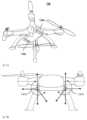
도 6a는 도 1a에서와 같이 폴디드 카메라를 포함하는 파노라마 스캐닝 범위를 갖는 카메라를 구비하는 플라잉 드론의 상측을 등측도법으로 도시한다.
도 6b는 도 6a의 드론의 저면을 등측도법으로 도시한다.
도 6c는 도 6b에 표시된 섹션의 확대도를 도시한다.
도 6d는 도 6a의 절단선 A-B를 따른 도 6a의 드론의 측면도를 도시한다.
도 7a는 파노라마 스캐닝 범위를 갖는 2 개의 카메라를 구비하는 플라잉 드론의 하부 측을 등측도법으로 도시하며, 여기서 각각의 카메라는 도 1a에서와 같이 폴디드 카메라를 포함한다.
도 7b는 도 7a의 드론의 측면도를 도시한다.
도 8a는 여기에 개시된 본 발명에 따라, 업라이트 카메라와 함께 도 1a에서의 폴디드 카메라를 포함하는 파노라마 스캐닝 범위를 갖는 카메라를 포함하는 TV 세트의 정면도를 도시한다.
도 8b는 도 8a의 TV 세트에서 코너 섹션의 확대를 정면도로 도시한다.
도 8c는 도 8a의 TV 세트에서 코너 섹션의 확대를 등측도법으로 도시한다.
도 9a는 (a) 제 1 사용자가 보는 화면 및 (b) FOVW상의 제 1 FOVT 위치를 가진 상태에서, 자율적인 FOVT 트래킹 동안 TV에 포함된 듀얼-카메라 배열에서의 FOVT 및 FOVW의 제 2 사용자가 보는 화면을 도시한다.
도 9b는 도 9a와 동일한 화면을 도시하지만, FOVW상의 제 2 위치에서 FOVT를 갖는다.
도 9c는 도 9a와 동일한 화면을 도시하지만, FOVW상의 제 3 위치에서 FOVT를 갖는다.Non-limiting examples of embodiments disclosed herein are described below with reference to the accompanying drawings listed following this paragraph. The same structure, component or part appearing in more than one drawing is generally indicated by the same numeral in all drawings. The drawings and detailed description are intended to illuminate and clarify the embodiments disclosed herein, and should not be considered limiting in any way.
1A schematically illustrates an exemplary embodiment of a camera having a panoramic scanning range including a folded camera in an isometric view, in accordance with the invention disclosed herein.
FIG. 1B shows the folded camera of FIG. 1A in the “zero” prism position.
FIG. 1C shows the folded camera of FIG. 1A with the prism rotated 30 degrees from zero about the folded camera optical axis.
1E schematically illustrates another exemplary embodiment of a camera having a panoramic scanning range, including a folded camera, in which a lens is fixedly attached to a prism, according to the invention disclosed herein.
1F schematically depicts another exemplary embodiment of a camera with a panoramic scanning range comprising a folded camera with a folded lens, in accordance with the invention disclosed herein.
Figure 2a schematically shows a rectangular image sensor smaller than the image circle and bounded by the image circle.
Fig. 2b schematically shows a square image sensor larger than the image circle and limiting the image circle.
3A illustrates scanning and obtaining a panoramic view using a camera having a panoramic scanning range, in accordance with the invention disclosed herein.
Fig. 3b shows 16 individual image sections of the panoramic view of Fig. 3a, each image section having a respective image circle and a respective cropped area defined by a 9:16 rectangle;
Fig. 3c shows the image section of Fig. 3b stitched into a panoramic image.
4A illustrates an isometric view of an exemplary embodiment of a smart phone including a camera with a panoramic scanning range, in accordance with the inventions disclosed herein.
Fig. 4B shows an enlarged cut-away view of the smartphone section of Fig. 4A.
FIG. 4C is an isometric view of the rear surface of an exemplary embodiment of a smart phone that includes a dual-aperture camera with an upright camera and a camera with a folded camera with a panoramic scanning range, in accordance with the inventions disclosed herein. .
Fig. 4d shows an enlarged cut-away view of the smartphone section of Fig. 4c.
FIG. 5A illustrates an isometric view of an exemplary embodiment of a smart phone including a camera with a panoramic scanning range with two folded cameras, in accordance with the invention disclosed herein.
Fig. 5b shows a rear view of the smart phone of Fig. 5a.
FIG. 6A is an isometric view of the top of a flying drone equipped with a camera having a panoramic scanning range including a folded camera as in FIG. 1A .
FIG. 6B is an isometric view of the bottom of the drone of FIG. 6A.
Fig. 6c shows an enlarged view of the section indicated in Fig. 6b.
FIG. 6D shows a side view of the drone of FIG. 6A along section line AB in FIG. 6A .
7a isometric view of the bottom side of a flying drone with two cameras with a panoramic scanning range, where each camera comprises a folded camera as in FIG. 1a.
7b shows a side view of the drone of FIG. 7a.
FIG. 8A shows a front view of a TV set including a camera with a panoramic scanning range including the folded camera in FIG. 1A together with an upright camera, in accordance with the invention disclosed herein.
Fig. 8b shows an enlargement of a corner section in the TV set of Fig. 8a in front view.
Fig. 8c shows an isometric view of a magnification of a corner section in the TV set of Fig. 8a.
9A shows FOV T and FOVW in a dual-camera array included in a TV during autonomous FOVT tracking, with (a) a screen viewed by a first user and (b) a first FOVT position on FOVW. A screen viewed by the second user of the screen is shown.
FIG. 9B shows the same screen as FIG. 9A , but with FOVT at the second position on FOVW.
Fig. 9c shows the same screen as Fig. 9a, but with FOVT at the third position on FOVW.
다음의 상세한 설명에서, 철저한 이해를 제공하기 위해 다수의 특정 세부 사항이 설명된다. 그러나, 여기에 개시된 발명은 이러한 특정 세부 사항 없이도 실시될 수 있음을 당업자는 이해할 것이다. 다른 경우에, 여기에 개시된 발명을 모호하게 하지 않기 위해 널리 알려진 방법은 상세하게 설명되지 않았다.In the detailed description that follows, numerous specific details are set forth in order to provide a thorough understanding. However, it will be understood by those skilled in the art that the invention disclosed herein may be practiced without these specific details. In other instances, well known methods have not been described in detail in order not to obscure the invention disclosed herein.
명확성을 위해, 별도의 실시 예들과 관련하여 설명된, 본 발명의 특정 특징들은 또한 단일 실시 예에서 조합하여 제공될 수 있다는 것이 이해된다. 반대로, 간결함을 위해, 단일 실시 예와 관련하여 설명된, 본 발명의 다양한 특징들은 개별적으로 또는 임의의 적절한 하위 조합으로 제공될 수 있다.For clarity, it is understood that certain features of the invention, which are described in the context of separate embodiments, can also be provided in combination in a single embodiment. Conversely, for brevity, the various features of the invention, which have been described in the context of a single embodiment, can be provided individually or in any suitable subcombination.
본원에 개시된 용어 "처리 유닛"은 예컨대 다양한 데이터 처리 동작들을 실행할 수 있는 컴퓨터 메모리에 동작되게 연결된 컴퓨터 처리 장치(예컨대, 디지털 신호 프로세서(DSP), 마이크로 컨트롤러, FPGA(필드 포로그램가능 게이트 어레이), ASIC(특정 용도용 집적 회로) 등)를 포함하는, 데이터 처리 회로를 갖는 임의의 종류의 전자 장치를 포함하는 것으로 광범위하게 해석되어야 한다.As used herein, the term “processing unit” refers to a computer processing device (e.g., a digital signal processor (DSP), microcontroller, FPGA (Field Programmable Gate Array), It should be broadly interpreted to include any kind of electronic device having data processing circuitry, including ASICs (application integrated circuits), etc.).
또한, 명확성을 위해, "실질적으로"라는 용어는 허용 가능한 범위 내에서 값의 변화 가능성을 암시하기 위해 본원에서 사용된다. 일 예에 따르면, 본 명세서에서 사용되는 "실질적으로"라는 용어는 임의의 특정 값의 위 또는 아래로 최대 10%의 가능한 변동을 의미하는 것으로 해석되어야 한다. 다른 예에 따르면, 본 명세서에서 사용되는 "실질적으로"라는 용어는 임의의 특정 값의 위 또는 아래로 최대 5%의 가능한 변동을 의미하는 것으로 해석되어야 한다. 추가의 예에 따르면, 본 명세서에서 사용되는 용어 "실질적으로"는 임의의 특정 값의 위 또는 아래로 최대 2.5%의 가능한 변동을 의미하는 것으로 해석되어야한다.Also, for clarity, the term “substantially” is used herein to imply a possible variation of a value within an acceptable range. According to one example, the term "substantially" as used herein should be interpreted to mean a possible variation of up to 10% above or below any particular value. According to another example, the term "substantially" as used herein should be interpreted to mean a possible variation of up to 5% above or below any particular value. By way of further example, the term "substantially" as used herein should be interpreted to mean a possible variation of up to 2.5% above or below any particular value.
이하 명세서 내용에서, "디지털 회전"은 광학 요소의 물리적 회전을 설명하는데 사용되는 "회전"과 구별하기 위해, 소프트웨어에 의한 이미지 회전을 나타내는데 사용된다.In the following text, "digital rotation" is used to refer to rotation of an image by software, to distinguish it from "rotation" used to describe the physical rotation of an optical element.
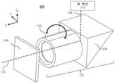
도 1a는 등측도법으로 도시된 폴디드 카메라(100, 이는 또한 "폴디드 카메라 모듈"이라고도 함)의 예시적인 실시 예를 개략적으로 도시한다. 도시된 직교 X-Y-Z 좌표("축") 시스템은 다음의 모든 도면에도 적용된다. 이 좌표계는 예시적이다. 카메라(100)는 렌즈 어셈블리(또는 간단히 "렌즈")(102), 광학 경로 폴딩 요소(OPFE)(104) 및 이미지 센서(106)를 포함한다. OPFE(104)는 (예시적인 좌표계에서) X 축에 실질적으로 평행한 축(108)을 따르며, 객체, 장면 또는 파노라마 뷰 섹션(114)로부터 OPFE로 향하는 제 1 광학 경로를, (예시적 좌표계에서) Z 축에 실질적으로 평행한 축(110)을 따르는 제 2 광학 경로로 폴딩한다. 축(110)은 렌즈(102)의 광축이다. 이미지 센서(106)는 축(110)에 평행하게 정렬된 수직평면을 갖는다. 즉, 이미지 센서(106)는 일반적으로 제 1 광학 경로에 실질적으로 직교하는 평면에 놓인 평면 객체에 놓인다. 이미지 센서(106)는 출력 이미지를 출력한다. 출력 이미지는 디모자이킹, 화이트 밸런스, 렌즈 쉐이딩 보정, 불량 픽셀 보정 및 ISP 설계 분야에 공지된 다른 프로세스를 위해 이미지 신호 프로세서(ISP-미도시)에 의해 처리될 수 있다. 일부 실시 예에서, ISP는 이미지 센서(106)의 일부일 수 있다. 광축(110)은 본 명세서에서 "폴디드 카메라 광축"으로 지칭될 수도 있다.1A schematically illustrates an exemplary embodiment of a folded camera 100 (also referred to as a “folded camera module”) shown in an isometric view. The illustrated Cartesian X-Y-Z coordinate ("axis") system also applies to all figures that follow. This coordinate system is exemplary.
일부 실시 예들에서, 카메라(100)는 축(110)을 따라 렌즈(102)를 이동(또는 "시프팅(shift)"또는 "작동(actuate)")시킬 수 있게 하는 포커스 또는 오토포커스(AF) 메커니즘(미도시)을 더 포함 할 수 있어서, 객체로부터의 이미지들을 다양한 거리에서 이미지 센서(106)에 포커싱할 수 있다. 간략화를 위해, 본 설명은 정규적(수동) 포커스를 또한 포함하는 것으로 이해하면서 AF만을 참조하여 계속된다. AF 작동 메커니즘은 일반적으로 보이스 코일 모터(VCM) 유형, 즉 "VCM 액추에이터"이다. 이러한 작동 메커니즘은 당 업계에 공지되어 있고, 예컨대 출원인의 공동 소유의 국제 특허 출원 PCT/IB2015/056004 및 PCT/IB2016/055308에 개시되어 있다. 그러나, 이것은 비-제한적인 예이며, AF 메커니즘은 스테퍼 모터, 형상 기억 합금(SMA) 액추에이터 또는 당 업계에 알려진 다른 유형과 같은 다른 유형일 수 있다. 일부 실시 예들에서, 카메라(100)는 AF 작동 메커니즘에 부가하여 또는 대신에 광학 이미지 안정화(OIS) 작동 메커니즘(미도시)을 포함할 수 있다. OIS는 예컨대 렌즈를 X-Y 평면에서 두 방향으로 이동시켜, Z 및 X 방향 중심으로의 카메라(100) 틸트를 보상함으로써, 달성될 수 있다. 3개의 자유도(DOF) OIS + 포커스 작동 메커니즘(이는 OIS를 위한 2가지의 이동 및 AF를 1가지 이동을 수행한다)은 일반적으로 VCM 유형이며, 예컨대 국제 특허 출원 PCT/US2013/076753 및 미국 특허 출원 2014/0327965에 개시되어 있다. 컴팩트형 폴디드 카메라에서의 오토포커스 및 OIS에 대한 자세한 내용은 출원인의 국제 특허 출원 PCT/IB2016/052143, PCT/IB2016/052179 및 PCT/IB2016/053335에서 확인할 수 있다.In some embodiments, the
공지된 폴디드 카메라 모듈(예컨대, PCT/IB2016/052179 참조)과 달리, 카메라(100)는 이미지 센서에 대해 축(110)(Z 축)을 중심으로 OPFE(104)를 회전시키도록 설계되는데, 여기서의 회전은 도시된 좌표계의 XY 평면에서 화살표(112)로 표시된 회전을 지시한다. OPFE(104)는 광학적 요건(아래 참조)에 의해 요구되는 각도 범위 내에서, 일부 경우에는 최대 180도까지, 다른 경우에는 최대 360도까지 회전할 수 있다. 도 1c는 30도 회전 후의 OPFE(104)를 도시한다. 도 1d는 원래 "제로 회전" 위치(도 1b에 도시됨)로부터 180도 회전 후의 OPFE(104)를 도시한다. 30도 및 180도 회전된 위치는 많은 회전 위치 범위의 예이다. 축(110) 중심으로의 OPFE의 회전은 예컨대 스테퍼 모터 또는 VCM 액추에이터(116)에 의해 구동될 수 있다. 본 명세서에 개시된 바와 같이 OPFE를 회전시키기 위해 사용될 수 있는 스테퍼 모터는 예컨대 Dr. Fritz Faulhaber Gmbh and Co.에 의해 제조된 스테퍼 모터 모델 FDM0620이다. 카메라(100) 및 액추에이터(116)는 함께 파노라마 스캐닝 범위를 갖는 카메라(130)를 형성한다(도 1a). 회전식 VCM 모터의 예는 공동 소유의 국제 특허 출원 PCT/IB2017/052383 및 PCT/IB2017/057706에서 실시 예로 제공된다.Unlike known folded camera modules (see e.g. PCT/IB2016/052179), the
일부 실시 예에서, 렌즈(102)는 광학적으로 축 대칭일 수 있다. 따라서, 축(110) 중심으로의 렌즈(102)의 임의의 회전은 시스템, 특히 이미지의 광학 특성을 변화시키지 않는다. 이러한 실시 예에서, 렌즈(102)는 OPFE(104)와 함께 회전 할 수 있다. 특히, 도 1e의 예시적인 실시 예에 도시된 바와 같이, 카메라(150)에서, 렌즈(102)는 렌즈-OPFE 어셈블리(152)를 형성하기 위해 OPFE(104)에 고정되게 부착(예컨대, 접착)될 수 있다. 도 1f의 예시적인 실시 예로 도시된 일부 실시 예에서, 카메라(160)에서, 렌즈와 OPFE는 "폴디드 렌즈"(162)(예컨대 Asus ZenFone Zoom 참조)를 형성하도록 결합될 수 있으며, 여기서 일부 렌즈 요소(예컨대, 도 1f에 도시된 단일 렌즈 요소(164))는 축(108)을 따라 촬영된 객체로부터의 광학 경로에서 OPFE 앞에 위치되는 반면, 다른 렌즈 요소는 광학 경로에서 이미지 센서를 향해(즉, 렌즈 어셈블리(102) 요소와 같이) OPFE 뒤에 위치된다. 이러한 실시 예에서, 전체 렌즈-OPFE 어셈블리(도 1e) 및/또는 폴디드 렌즈(도 1f)는 이미지 센서에 대해 회전할 것이다. 아래 및 위의 모든 설명에서, 카메라(150 및/또는 160)는 응용 및/또는 분석 및/또는 작동 방법에서 카메라(100)를 대체할 수 있다.In some embodiments,
"α"도 만큼 이미지 센서에 대한 축(110) 중심으로의 OPFE(104) 회전은 축(108)(이는 회전 이전의 원래 상태에서 도시된 좌표계에서 X 축에 직각으로 위치됨)이 X-Y 평면 내에서 회전하게 할 것이고, 이는 이미지 센서 상의 이미지에 두 가지의 변화를 일으킨다: a) 센터 시야(FOV)의 α도 만큼의 회전, 및 b) 이미지 센서 상의 이미지의 α도 만큼의 회전(이는 "롤(Roll)" 효과로 당 업계에 알려짐).Rotation of
전술한 바와 같이 OPFE의 회전 및 그에 따른 제 1 광학 경로의 회전은 파노라마 뷰의 촬영을 가능하게 한다. 카메라(100)는 파노라마 스캐닝 범위를 갖는다. 파노라마 뷰(및 스캐닝 범위)는 최대 360 도이다. 이하에서, "서브-뷰", "이미지 섹션" 또는 "뷰 섹션"으로도 지칭되는 복수의 사진들이 [여기서, 각각의 서브-뷰는 특정 OPFE 회전 위치를 반영하거나 특정 OPFE 회전 위치와 관련됨] 획득되어, "파노라마 출력 이미지"로 "스티칭"될 수 있다.As described above, rotation of the OPFE and thus rotation of the first optical path enables imaging of a panoramic view. The
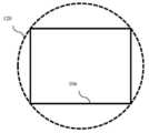
렌즈(102)의 "이미지 서클"(도 2a 및 도 2b 참조)은 이미지 센서의 센서 평면상의 원으로 정의되며, 여기에서는 포인트(150)(축(110)이 이미지 센서 평면과 만나는 지점)에서 센서 평면에 도달하는 광량에 비해 충분한 양의 광이 도달한다. 이미지 서클 내의 센서 픽셀만이 출력 이미지로 사용될 수 있다. 이미지 서클 외부의 센서 픽셀은 촬영된 객체/장면으로부터 충분한 빛을 받지 못하고, 노이즈한 품질의 이미지를 야기시킨다. 이미지 서클은 이미지 센서보다 크거나 작을 수 있다.The “image circle” of lens 102 (see FIGS. 2A and 2B ) is defined as a circle on the sensor plane of the image sensor, where the sensor at point 150 (the point where
도 2a는 (예컨대, 3:4 에지 길이 비를 갖는) 직사각형 이미지 센서(106)가 이미지 서클(120)보다 작고, 따라서 이미지 서클이 이미지 센서를 "제한하는(bounding)" 일 실시 예를 도시한다. 여기에서, 사각형의 에지는 이미지 서클의 직경보다 작으며, 모든 센서 픽셀은 이미지 서클 안에 있다. 도 2b는 (예컨대) 정사각형 이미지 센서(106)가 이미지 서클(120)보다 더 크고, 따라서 이미지 센서가 이미지 서클을 "제한하는" 다른 실시 예를 도시한다. 여기에서, 사각형의 에지는 이미지 서클의 직경보다 크다. 이미지 센서에서 획득된 이미지는 일반적으로 직사각형 모양이며, 일반적으로 긴 에지와 짧은 에지 치수 사이의 비율이 3:4 또는 9:16이다. 카메라(100)에서, 이미지 센서(106)는 도 2b에서와 같이, 이미지 서클(120)보다 더 크다. 도 2b에서의 이미지 센서(106)의 최소 치수는 최소 요구 센서 크기의 예이다. 따라서, 카메라(100)에서, 가장 큰 가능한 이미지는 이미지 서클(120) 상에 놓인 에지를 갖는 임의의 경계지어진 직사각형이다. 이 직사각형은 후술하는 바와 같이, 상이한 동작 하에서 이미지 센서(106)의 에지에 대해 어느 정도 회전될 수 있다.2A illustrates an embodiment in which a rectangular image sensor 106 (eg, with a 3:4 edge length ratio) is smaller than the
도 2b는 또한 센서(106)로부터 취해진 (3:4 에지 길이 비율을 갖는)직사각형 출력 이미지 방향의 3 가지 예를 도시한다: "가로(landscape)" 방향의 이미지(202)(더 긴 직사각형 에지는 수평임), 가로 방향에 비해 30도 만큼 회전된 이미지(204), 및 "세로(portrait)" 방향의 이미지(206)(더 긴 직사각형 에지는 수직 임). 카메라(100)는 임의의 단일 프레임을 세로 또는 가로 방향으로 출력하는데 사용될 수 있다. 부착된 처리 유닛(도시되지 않음)을 사용하여 방향의 선택이 디지털 방식으로 수행될 수 있다.2b also shows three examples of rectangular output image orientations (with a 3:4 edge length ratio) taken from sensor 106:
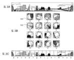
도 3a, 도 3b 및 도 3c는 파노라마 뷰를 스캐닝 및 획득하기 위한 카메라(100)의 사용 방법(용법)의 실시 예를 도시한다. 도 3a는 360도(수평축) x 56도(수직축) 시야(FOV)를 갖는 파노라마 뷰를 도시한다. 파노라마 뷰는 편평한(flattened) 이미지로 표시되는데, 여기서 편평한 이미지는 360 도의 원형 뷰를 나타내는 것으로 이해된다. 도 3b는 OPFE(104)가 수평 축을 따라 서브-뷰들 사이에서 22.5 도의 점프 크기를 가지면서 0에서 360 도로 회전될 때, 이미지 센서(106) 상에 캡처된, 파노라마 뷰의 16 개의 개별 뷰 섹션(서버-뷰) "a" 내지 "o"를 도시한다. 다른 경우에, 다른 점프 크기가 서브-뷰 사이에서 사용될 수 있다. 도 3b는 각각의 서브-뷰에 대해, 각각의 이미지 서클(120) 및 9:16 직사각형에 의해 한정된 각각의 크로핑 영역(132)을 도시한다. 간략화를 위해, 이미지 서클(120)은 서브-뷰 "a"에만 표시되고, 크로핑 영역(132)은 서브-뷰 "e"에만 표시된다. 크로핑 영역은 크로핑된 이미지를 제공한다. 크로핑된 이미지는 원래 방향(서브-뷰 "i")으로 디지털 회전될 수 있다. 카메라(100)는 적절한 회전 후에 임의의 서브-뷰 "a" 내지 "o"(또는 임의의 회전 각도에서의 임의의 서브-뷰)를 단일 프레임으로서 출력할 수 있다. 도 3c는 도 3b의 서브-뷰 크로핑된 이미지의 파노라마 이미지로의 재구성("스티칭")을 도시한다. 일반적으로, 각각 주어진 FOV를 갖는 2 개의 인접한 이미지의 스티칭은 다음의 동작을 필요로 한다: (a) 2 개의 이미지 사이의 기울기, 회전, 시프트 및 다른 편차를 검출하는 단계; (b) 편차를 정정하기 위해 적어도 하나의 이미지를 보정된 이미지로 디지털 변환하는 단계; 및 (c) 2 개의 인접한 보정된 이미지를, 2 개의 원래 제공된 FOV보다 큰 연속하는 FOV를 갖는 단일 이미지로 디지털 결합하는 단계. 디지털 회전 및 스티칭 동작은 당 업계에 공지된 소프트웨어를 사용하여 수행될 수 있다. 소프트웨어는 카메라(100)와 함께 카메라(130)를 구비하는 장치 또는 시스템의 칩셋의 일부일 수 있거나 또는 카메라(100)를 원격으로 작동시킬 수 있는 처리 유닛(도시되지 않음)상에서 실행될 수 있다. 인접한 2 개의 이미지가 작은 영역에 걸쳐, 예컨대 단일 이미지의 FOV의 10%-30% 정도 오버랩됨에 유의하라. 오버랩 영역은 (a) 및 (c)에서의 동작을 위해 필요하다. 다른 경우, 카메라(100)는 상이한 FOV, 예컨대 수평 축에서 360도 미만, 및/또는 예컨대 수직 축에서 56도 이상 또는 미만의 파노라마 뷰를 스캐닝하는데 사용될 수 있다.3A, 3B and 3C show an embodiment of a method (usage) of the
다른 실시 예에서, 카메라(100)는 운영 장치 스크린상에서 비디오를 찍거나 비디오의 미리보기를 위해 사용될 수 있다(아래의 운영 장치 예 참조). 스캐닝 기능을 사용하면, 비디오 시야를 선택할 수 있다. 아래의 예(도 8 내지 도 9)는 스캐닝 FOV 기능을 갖는 비디오 레코딩 및 스트림을 도시한다. OPFE(104)의 회전 시, 카메라의 FOV가 변하고, 회전된 이미지가 센서(106)상에서 획득된다. 카메라(100) 및 부착된 처리 유닛(도시되지 않음)은 프레임 및 비디오 스트림을 디지털 방식으로 회전 방지하여, (도 3 및 도 9에 제시된 바와 같이) 원래의 방향으로 정렬된 비디오를 보여줄 수 있다. 최종 출력은 최대 360 도의 스캐닝 범위를 가진 비디오 영화를 보여줄 수 있다.In another embodiment,
카메라(100)를 구비한 카메라(120)와 같은 시스템을 구비하거나 포함하는 플랫폼의 여러 비-제한적인 예(예컨대, 스마트 폰 및 플라잉 드론)가 도 4 내지 도 7에 제시되어 있다.Several non-limiting examples of platforms having or including systems such as
도 4a는 등측도법으로 도시한 도면이고, 도 4b는 예시적인 실시 예의 확대 절개 섹션을 도시하며, 플랫폼은 스마트 폰(400)과 같은 모바일 장치이다. 스마트 폰(400)은 카메라(100)와 같은 폴디드 카메라(100') 및 액추에이터(116)과 같은 스테퍼 모터 또는 VCM을 포함하는, 파노라마 스캐닝 범위를 갖는 카메라(430)를 포함한다. 카메라(100')는 스마트 폰(400)의 에지(402)에 가까운 측에 위치된다. 도 4b의 확대도에 제공된 절개부(404)는 카메라(100')(렌즈(102), 프리즘(104) 및 센서(106)) 및 스테퍼 모터 또는 VCM 액추에이터(116)의 주요 구성 요소를 도시한다. 프리즘(104)은 예컨대 유리 또는 플라스틱으로 만들어진 보호용 파노라마 투명 스크린(406) 뒤에 위치된다. 스마트 폰(400)에서, 카메라(100')의 일 용도는 점선 반원 화살표(408)로 도시된 동작인 180도 파노라마 사진을 찍는 것일 수 있다. 예시적인 사용 실시 예에서, 스마트 폰(400)의 카메라(100')는 스마트 폰의 "전면 카메라" 및 "후면 카메라"로서 사용될 수 있고, "전면 카메라" 및 "후면 카메라"는 당 업계에 잘 알려진 의미를 갖는다.FIG. 4A is an isometric view, and FIG. 4B shows an enlarged cutaway section of an exemplary embodiment, wherein the platform is a mobile device such as a
일부 실시 예에서, 본 명세서에 개시된 파노라마 스캐닝 범위를 갖는 폴디드 카메라는 듀얼-애퍼처(또는 "듀얼-카메라") 카메라 배열에서 비-접이식("업라이트") 비-스캐닝 카메라와 함께 위치될 수 있다. 비-접이식 카메라는 폴디드 카메라의 FOV보다 작거나, 같거나 또는 더 큰 FOV를 가질 수 있다. 폴디드 카메라 및 비-접이식 카메라를 포함하는 듀얼-애퍼처 카메라는 예컨대 PCT/IB2015/056004에 설명되어 있다. 듀얼 카메라는 스마트 폰 또는 다른 개인 전자 장치에 위치될 수 있다. 업라이트 카메라는 스마트 폰의 전면 카메라 또는 후면 카메라 일 수 있다.In some embodiments, a folded camera with a panoramic scanning range disclosed herein may be co-located with a non-folding (“upright”) non-scanning camera in a dual-aperture (or “dual-camera”) camera arrangement. there is. A non-folding camera may have a FOV that is less than, equal to, or greater than the FOV of a folded camera. A dual-aperture camera including a folded camera and a non-folded camera is described, for example, in PCT/IB2015/056004. The dual camera may be located in a smart phone or other personal electronic device. The upright camera can be either the front camera or the back camera of a smartphone.
도 4c는 등측도법으로 도시한 도면이고, 도 4d는 업라이트 카메라(412), 및 파노라마 스캐닝 범위(100')를 갖는 폴디드 카메라를 갖는 카메라(430)를 갖는 이러한 듀얼-애퍼처 카메라(450)를 포함하는 스마트 폰(400')의 예시적 실시 예의 확대 절개 섹션을 도시한다. 도시된 다른 모든 구성 요소는 도 4a 및 4b의 구성 요소와 유사하다. 카메라(412)는 스마트 폰(400')의 후면 카메라로 도시되어 있지만, 다른 실시 예에서는(전술 한 바와 같이), 전면 카메라 일 수 있다.4C is an isometric view, and FIG. 4D shows this dual-
도 5a는 등측도법으로 도시한 도면이고, 도 5b는 플랫폼이 스마트 폰(500)인 예시적인 실시 예의 배면도를 도시한다. 스마트 폰(500)은 카메라(100)와 같은 2 개의 폴디드 카메라뿐만 아니라 관련된 스테퍼 모터 또는 VCM 액추에이터(도시되지 않음)를 포함하는 파노라마 스캐닝 범위를 갖는 카메라(530)를 포함한다. 100'a 및 100'b로 표시된 2 개의 카메라는 예컨대 스마트 폰(500)의 각각의 에지(502a 및 502b)에 가까운 2 개의 대향 측면 상에 위치된다. 도 5b는 또한 각각의 카메라(렌즈(102), 프리즘(104) 및 센서(106))의 주요 구성 요소를 도시한다. 각각의 스테퍼 모터 또는 VCM 액추에이터는 도면을 단순화하기 위해 도시되지 않았다. 각각의 프리즘(104)은 예컨대 유리 또는 플라스틱으로 만들어진 각각의 보호용 파노라마 투명 스크린(506) 뒤에 위치된다. 스마트 폰(500)에서, 각각의 카메라(100'a 및 100'b)의 1 회 사용은 2 개 각각의 180도 파노라마 사진을 촬영한 것이 될 수 있고, 이는 1 개의 360도 파노라마 사진으로 스티칭될 수 있다.FIG. 5A is an isometric view, and FIG. 5B shows a rear view of an exemplary embodiment in which the platform is a
도 6a 내지 도 6d는 카메라(100)를 구비하는 다른 예시적인 플랫폼을 도시한다. 도 6a 내지 도 6d에 도시된 바와 같이, 플랫폼은 카메라(100)와 같은 폴디드 카메라(100') 및 액추에이터(116)와 같은 스테퍼 모터 또는 VCM 액추에이터를 포함하는 파노라마 스캐닝 범위를 갖는 카메라(630)를 구비하는 플라잉 드론(600)이다. 드론(600)은 비행 및 높은 곳으로부터 사진 촬영을 위해 사용된다. 도 6a는 상측으로부터 바라본 등측도법의 드론을 도시하고, 도 6b는 하측으로부터 바라본 등측도법의 드론을 도시하고, 도 6c는 도 6b에 표시된 부분의 확대도이다. 도 6d는 도 6a의 절단선 A-B를 따른 드론(600)의 절단 측면도이다. 시스템(600)에서, 카메라는 +90도(상방 주시, 651), 0도(전방 주시, 652), -90도(하방 주시, 654), -120도(하방 약간 뒷쪽 주시, 653) 사이에서, 즉 총 210 도로 촬영 각도(도 6d에 표시됨)를 변경하는데 사용된다. 다른 예에서, 스캐닝 범위는 변할 수 있다. 드론(600) 내의 카메라(100)는 공동 소유의 국제 특허 출원 PCT/IB2016/057366에서 뿐만 아니라, 도 8 및 도 9를 참조하여 후술되는 바와 같이 객체를 자율적으로 트래킹할 수 있다.6A-6D show another exemplary platform having a
도 7a 및 도 7b는 파노라마 스캐닝 범위를 갖는 2 개의 카메라(730a 및 730b)를 구비하는 또 다른 플라잉 드론(700)을 도시하는데, 여기서 각각의 카메라는 카메라(100)와 같은 폴디드 카메라 및 액추에이터(116)(도시되지 않음)와 같은 스테퍼 모터 또는 VCM 액추에이터를 포함한다. 이 구성에서, 2개의 카메라는 360도 스캐닝 범위에서 사진을 찍을 수 있다. 화살표로 표시된 촬영 각도는 도 6d의 각도와 유사하다.7A and 7B show another flying
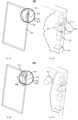
도 8a 내지 도 8c는 카메라(100)를 구비하는 또 다른 예시적인 플랫폼을 도시한다. 도 8a 내지 도 8c에 도시된 바와 같이, 플랫폼은 텔레비전(TV) 세트(800)이다. TV 세트(800)는 카메라(100)와 같은 폴디드 카메라 및 액추에이터(116)와 같은 스테퍼 모터 또는 VCM 액추에이터를 포함하는 파노라마 스캐닝 범위를 갖는 카메라(830)를 포함한다. TV 세트(800)는 업라이트 카메라(812) 및 TV 스크린(802)를 더 포함한다. 업라이트 카메라(812)는 렌즈(814) 및 이미지 센서(816)를 포함한다. TV 세트(800)는 하나 이상의 스피커 및 하나 이상의 마이크로폰뿐만 아니라 다른 잘 알려진 구성 요소(도시되지 않음)를 더 포함할 수 있다.8A-8C show another exemplary platform with a
도 8a는 TV 세트(800)의 정면도를 도시한다. 도 8b는 TV 세트(800) 및 카메라(812 및 830)에서의 코너 섹션의 확대를 정면도로 도시한다. 도 8c는 도 8b에 도시된 섹션 및 카메라(830)에서 프리즘(104)의 가능한 회전을 등측도법으로 도시한다. 카메라(812)는 수평면에서 예컨대 120-180 도의 와이드(큰) FOV를 가질 수 있으며, 또한 와이드 카메라(812)로 지칭된다. 카메라(812)의 FOW는 와이드 FOV(FOVW)로 지칭된다. TV 세트(800)에서, 카메라(830)는 수평면에서 예컨대 30-80 도의 텔레(좁은) FOV를 가질 수 있다. 따라서, TV 세트(800)에서, 카메라(830)는 "텔레 카메라"(830)로도 지칭될 수 있고, 카메라(830)의 FOV는 텔레 FOV(FOVT)로 지칭될 수 있다.8A shows a front view of
TV 세트(800)에서, 카메라(812 및 830)는 TV 세트(800)의 좌측 상단 코너에 위치된다. 다른 예시적인 실시 예에서, 카메라(812 및 830)는 상단 중앙, 좌측 또는 우측, 하단 측면 또는 심지어 아래에서 설명되는 스크린(802) 너머와 같이 다른 위치에 위치될 수 있다. 다른 예시적인 실시 예에서, 카메라(812 및 830)는 TV 세트 외부의 개별 모듈(박스)에 위치될 수 있고, 케이블 또는 무선 연결을 통해 연결될 수 있다.In
예시적인 사용 실시 예에서, TV 세트(800)는 다음과 같이 화상 회의에 사용될 수 있다: 제 1 위치에 위치한 제 1 사용자(사람)는 제 2 위치에 위치한 제 2 사용자(사람)와 통신하기 위해 TV 세트(800)를 사용할 수 있다. 제 2 사용자는 예컨대 TV, 스마트 폰, 개인용 컴퓨터, 노트북 또는 랩톱 컴퓨터 등과 같이 스크린을 포함하는 임의의 전자 장치를 사용할 수 있다. 예시적인 실시 예에서, 카메라(830 및 812)는 제 1 사용자를 비디오 녹화하기 위해 사용될 수 있는 한편, 제 2 사용자는 그의 스크린에서 카메라(830 및 812)로부터의 기록을 볼 수 있다.In an exemplary use case, the
TV 세트(800)는 예컨대 자율적인 방식으로 객체를 트래킹하기 위하여 FOVT의 자동 이동 또는 "자동 조정"에 사용될 수 있다. 객체 또는 관심 객체를 트래킹하기 위해 자동 텔레 FOV 이동을 수행하는 카메라 모드는 본 명세서에서 자율 텔레 FOV 트래킹으로 지칭된다. 본 명세서에 적용 가능한 예시적인 자율 트래킹 시스템 및 방법은 스마트 폰 시스템을 위한 PCT/IB2016/057366에 기재되어 있다. 자율 FOVT 이동은 객체 또는 관심 객체의 인식(예컨대 카메라(812)를 통한)에 응답하고, 텔레 이미지는 객체 또는 관심 객체에 포커스를 맞추고 디스플레이한다. 객체 인식은 공지된 임의의 방법을 사용하여 수행될 수 있다.The
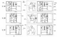
TV 세트(800)를 사용하는 자율 FOVT 트래킹 시나리오의 예가 도 9a 내지 도 9c에 도시되어 있다. 예시적인 실시 예에서, 카메라(812)는 제 1 위치에서의 와이드 뷰 이미지를 찍을 수 있다. 카메라(830)는 화상 회의 동안, 제 1 사용자가 카메라(812)의 FOVW 내에서 그리고 FOVW 근처에서 이동할 때, 제 1 사용자(902)를 트래킹할 수 있다. 제 2 사용자는 자신의 스크린에서 (1) 와이드 FOV, (2) 트래킹 후의 텔레 FOV 또는 (3) 와이드 및 텔레 FOV 모두를 볼 수 있다. 텔레 카메라는 관심 객체를 트래킹하기 위해 프리즘을 틸팅함으로써 그 FOV를 변경할 수 있다고 가정한다. 이상적으로, 카메라는 그것이 조정 가능한 텔레 FOV의 중앙에 가능한 근접하게 있도록, 객체를 트래킹한다.An example of an autonomous FOVT tracking scenario using the
도 9a는 자율 FOVT 트래킹 동안, FOVW상의 제 1 FOVT 위치를 갖는 텔레 카메라(830) 및 와이드 카메라(812)의 FOV를 도시한다. 도 9b는 FOVW상의 제 2 FOVT 위치를 갖는 도 9a의 FOV를 도시한다. 도 9c는 FOVW상의 제 3 FOVT 위치를 갖는 도 9a의 FOV를 도시한다. 이들 각각의 도면에서, 관심 객체는 제 1 사용자(902)이다.9A shows the FOVs of a
도시된 특정 예에서, 2개의 카메라로부터의 비디오 스트림을 나란히 볼 수 있다: 열(a)는 제 1 사용자가 보는 FOVW 및 FOVT를 가진 스크린(900a)을 도시하는 한편, 열(b)는 FOVW 및 FOVT를 갖는 제 2 사용자를 우측 스크린(900b) 상에, 그리고 제 1 사용자(902)의 얼굴 및 신체 일부 및 배경 일부의 확대된 텔레 뷰(이미지)를 좌측에 도시한다. 일반적으로, (a)에서의 FOVT는 제 1 사용자(도시된 바와 같이), 제 2 사용자 또는 장면으로부터의 다른 특징을 보여줄 수 있다. 따라서, 제 1 사용자를 보여주는 (a)의 FOVT는 제한적인 것으로 간주되어서는 안된다. 일반적으로, 제 2 사용자(도시되지 않음)는 그의 스크린에서 카메라(812) 또는 카메라(830)로부터, 또는 카메라(812 및 830) 모두로부터의 비디오 스트림을 동시에(예컨대, 나란히) 볼 수 있다. 제 2 사용자가 하나의 비디오 스트림만을 볼 경우, 예컨대 공동 소유의 미국 특허 제9185291호에 기술된 바와 같이, 스무스한 트랜지션 기술을 사용하여 스트림 사이의 스위칭이 수행될 수 있다.In the particular example shown, video streams from two cameras can be viewed side-by-side: column (a) shows
제 1 사용자를 트래킹하는 결정은 제 1 사용자, 제 2 사용자(예컨대, 원격 제어 사용에 의해)에 의해 또는 자동으로(예컨대, 얼굴 검출을 사용하여) 이루어질 수 있다. 텔레 카메라는 상기 개시된 바와 같이, 관심 객체를 트래킹하기 위해 프리즘을 회전시킴으로써 그 FOV를 변경할 수 있다고 가정한다. 이상적으로, 카메라는 각 도면에서 (b)의 왼쪽에서 볼 수 있듯이, 조정 가능한 FOVT의 중심에 가능한 근접하게 있도록, 객체를 트래킹한다.The determination to track the first user may be made by the first user, the second user (eg, by use of a remote control) or automatically (eg, using face detection). Assume that the telecamera can change its FOV by rotating the prism to track the object of interest, as described above. Ideally, the camera tracks the object so that it is as close as possible to the center of the adjustable FOVT , as seen on the left in (b) in each figure.
카메라(812) 및/또는 카메라(830)로부터의 비디오 스트림은 나중에 사용하기 위해 기록될 수 있으며, 이는 이미지 처리, 비디오 스트림 블렌딩 등과 같은 추가적인 처리를 포함할 수 있다.Video streams from
본 개시는 특정 실시 예들 및 일반적으로 관련된 방법들과 관련하여 설명되었지만, 실시 예들 및 방법들의 변경 및 치환은 당업자에게 명백할 것이다. 예컨대, 파노라마 스캐닝 범위를 갖는 카메라 및 폴디드 카메라는 스마트 폰, 플라잉 드론 및 텔레비전 세트에 예시적으로 통합된 것으로 설명되지만, 이러한 카메라 및 폴디드 카메라는 또한 차량과 같은 다른 플랫폼에 통합되거나 또는 스마트 폰과 다른 플랫폼, 예컨대 태블릿, 랩톱 컴퓨터, 패블릿, 데스크톱 컴퓨터, 스마트 스피커, 스마트 시계, 전자 서적 리더, 스마트 안경, 스마트 헬멧, 베이비 모니터, 증강 현실 시스템, 가상 현실 시스템, ADAS(첨단 운전자 보조 시스템) 등에 통합될 수 있다. 본 개시사항은 여기에 설명된 특정 실시 예들에 의해 제한되지 않고 첨부된 청구 범위의 범위에 의해서만 제한되는 것으로 이해되어야 한다.Although the present disclosure has been described with reference to specific embodiments and generally related methods, variations and permutations of the embodiments and methods will become apparent to those skilled in the art. For example, cameras with panoramic scanning range and folded cameras are described as illustratively integrated into smart phones, flying drones and television sets, but such cameras and folded cameras can also be integrated into other platforms such as vehicles or smart phones. and other platforms, such as tablets, laptop computers, phablets, desktop computers, smart speakers, smart watches, e-book readers, smart glasses, smart helmets, baby monitors, augmented reality systems, virtual reality systems, advanced driver assistance systems (ADAS) etc. can be incorporated. It should be understood that the present disclosure is not limited by the specific embodiments described herein, but only by the scope of the appended claims.
달리 언급되지 않는 한, 선택을 위한 옵션 리스트의 마지막 두 멤버 사이에 "및/또는"이라는 표현의 사용은 나열된 옵션 중 하나 이상이 적절하며, 선택될 수 있음을 나타낸다.Unless otherwise stated, use of the word "and/or" between the last two members of a list of options for selection indicates that one or more of the listed options are appropriate and may be selected.
청구 범위 또는 명세서가 "a" 또는 "an" 요소를 언급하는 경우, 그러한 참조는 그 요소 중 단지 하나만 존재하는 것으로 해석되지 않아야 한다는 것을 이해해야 한다.It should be understood that where a claim or specification refers to "a" or "an" elements, such reference should not be construed as indicating the presence of only one of the elements.
본 명세서에 언급된 모든 참고 문헌은 각각의 개별 참조가 본원에 참고로 구체적이고 개별적으로 포함되는 것과 동일한 정도로, 본 명세서에 참고로 전체적으로 포함된다. 또한, 본 출원서에서 임의의 참조의 인용 또는 식별은 이러한 참조가 본 발명의 선행 기술로서 이용 가능하다는 인정으로 해석되어서는 안된다.All references mentioned herein are hereby incorporated by reference in their entirety to the same extent as if each individual reference was specifically and individually incorporated by reference. Furthermore, citation or identification of any reference in this application is not to be construed as an admission that such reference is available as prior art to the present invention.
Claims (45)
Translated fromKorean제 1 시야(FOV1)를 갖는 제 1 폴디드 디지털 카메라를 포함하고, 상기 제 1 폴디드 디지털 카메라는 제 1 렌즈 광축을 갖는 제 1 렌즈, 제 1 이미지 센서, 및 객체 또는 장면으로부터의 제 1 광학 경로를 제 2 광학 경로로 폴딩하는 제 1 광학 경로 폴딩 요소(OPFE1)를 포함하고, 전체 제 1 렌즈는 상기 OPFE1과 상기 제 1 이미지 센서 사이에 위치하고, 상기 제 2 광학 경로는 상기 제 1 렌즈 광축과 실질적으로 평행하고, 상기 제 1 렌즈는 상기 OPFE1에 고정되게 부착되며 제 1 파노라마 스캐닝 범위에서 상기 제 1 이미지 센서에 대하여 상기 제 1 렌즈 광축을 중심으로만 상기 OPFE1와 함께 회전 가능하고, 상기 제 1 폴디드 디지털 카메라는 스마트폰의 제 1 측면 에지에 가까운 측에 위치하고, 상기 OPFE1은 스마트폰의 전면, 제 1 측면 에지 및 후면 사이에 연장되는 파노라마 투명 스크린 뒤에 위치하는 스마트폰.As a smartphone
A first folded digital camera having a first field of view (FOV1), the first folded digital camera comprising: a first lens having a first lens optical axis, a first image sensor, and a first optic from an object or scene; a first optical path folding element (OPFE1) for folding a path into a second optical path, wherein an entire first lens is positioned between the OPFE1 and the first image sensor, and the second optical path extends along an optical axis of the first lens is substantially parallel to, wherein the first lens is fixedly attached to the OPFE1 and is rotatable together with the OPFE1 only about the optical axis of the first lens with respect to the first image sensor in a first panoramic scanning range; 1 The smartphone according to claim 1 , wherein a folded digital camera is located on a side close to a first side edge of the smartphone, and the OPFE1 is located behind a panoramic transparent screen extending between the front side, the first side edge, and the back side of the smartphone.
b) 제 1 광학 경로를 원하는 제 1 방향으로 설정하기 위해 제 1 파노라마 스캐닝 범위 내에서 상기 OPFE1과 함께 상기 제 1 렌즈를 회전시키는 단계;
c) 이미지를 촬영하는 단계; 및
d) 촬영된 이미지를 처음의 원래 방향으로 다시 디지털 방식으로 회전시키는 단계;
를 포함하는 방법.a) providing a smart phone, wherein the smart phone includes a first folded digital camera having a first field of view (FOV1), the first folded digital camera having a first lens having a first lens optical axis; a first image sensor and a first optical path folding element (OPFE1) for folding a first optical path from an object or scene into a second optical path, wherein an entire first lens is formed between the OPFE1 and the first image sensor. , wherein the second optical path is substantially parallel to the optical axis of the first lens, the first lens is fixedly attached to the OPFE1, and the optical axis of the first lens is fixedly attached to the OPFE1 with respect to the first image sensor in a first panoramic scanning range. rotatable together with the OPFE1 only around the center, the first folded digital camera is located on a side close to the first side edge of the smartphone, and the OPFE1 extends between the front side, the first side edge, and the rear side of the smartphone. being located behind a panoramic transparent screen;
b) rotating the first lens with the OPFE1 within a first panoramic scanning range to set a first optical path in a first desired direction;
c) taking an image; and
d) digitally rotating the captured image back to its initial original orientation;
How to include.
Priority Applications (1)
| Application Number | Priority Date | Filing Date | Title |
|---|---|---|---|
| KR1020237015154AKR102770496B1 (en) | 2017-03-15 | 2018-02-13 | Camera with panoramic scanning range |
Applications Claiming Priority (5)
| Application Number | Priority Date | Filing Date | Title |
|---|---|---|---|
| US201762471662P | 2017-03-15 | 2017-03-15 | |
| US62/471,662 | 2017-03-15 | ||
| US201762560684P | 2017-09-20 | 2017-09-20 | |
| US62/560,684 | 2017-09-20 | ||
| PCT/IB2018/050885WO2018167581A1 (en) | 2017-03-15 | 2018-02-13 | Camera with panoramic scanning range |
Related Child Applications (1)
| Application Number | Title | Priority Date | Filing Date |
|---|---|---|---|
| KR1020237015154ADivisionKR102770496B1 (en) | 2017-03-15 | 2018-02-13 | Camera with panoramic scanning range |
Publications (2)
| Publication Number | Publication Date |
|---|---|
| KR20190117644A KR20190117644A (en) | 2019-10-16 |
| KR102530535B1true KR102530535B1 (en) | 2023-05-08 |
Family
ID=63522626
Family Applications (3)
| Application Number | Title | Priority Date | Filing Date |
|---|---|---|---|
| KR1020197026800AActiveKR102530535B1 (en) | 2017-03-15 | 2018-02-13 | Cameras with panoramic scanning range |
| KR1020237015154AActiveKR102770496B1 (en) | 2017-03-15 | 2018-02-13 | Camera with panoramic scanning range |
| KR1020257004708APendingKR20250028499A (en) | 2017-03-15 | 2018-02-13 | Camera with panoramic scanning range |
Family Applications After (2)
| Application Number | Title | Priority Date | Filing Date |
|---|---|---|---|
| KR1020237015154AActiveKR102770496B1 (en) | 2017-03-15 | 2018-02-13 | Camera with panoramic scanning range |
| KR1020257004708APendingKR20250028499A (en) | 2017-03-15 | 2018-02-13 | Camera with panoramic scanning range |
Country Status (6)
| Country | Link |
|---|---|
| US (3) | US10645286B2 (en) |
| EP (2) | EP4357832A3 (en) |
| JP (1) | JP2020512581A (en) |
| KR (3) | KR102530535B1 (en) |
| CN (3) | CN110582724B (en) |
| WO (1) | WO2018167581A1 (en) |
Families Citing this family (76)
| Publication number | Priority date | Publication date | Assignee | Title |
|---|---|---|---|---|
| KR101634516B1 (en) | 2013-06-13 | 2016-06-28 | 코어포토닉스 리미티드 | Dual aperture zoom digital camera |
| US9857568B2 (en) | 2013-07-04 | 2018-01-02 | Corephotonics Ltd. | Miniature telephoto lens assembly |
| JP2016523389A (en) | 2013-07-04 | 2016-08-08 | コアフォトニクス リミテッド | Compact telephoto lens assembly |
| CN108989649B (en) | 2013-08-01 | 2021-03-19 | 核心光电有限公司 | Slim multi-aperture imaging system with autofocus and method of use |
| US9392188B2 (en) | 2014-08-10 | 2016-07-12 | Corephotonics Ltd. | Zoom dual-aperture camera with folded lens |
| CN112433331B (en) | 2015-01-03 | 2022-07-08 | 核心光电有限公司 | Miniature telephoto lens module and camera using the same |
| CN112394467B (en) | 2015-04-16 | 2023-06-09 | 核心光电有限公司 | Autofocus and Optical Image Stabilization in a Compact Folding Camera |
| US10230898B2 (en) | 2015-08-13 | 2019-03-12 | Corephotonics Ltd. | Dual aperture zoom camera with video support and switching / non-switching dynamic control |
| KR102369223B1 (en) | 2015-12-29 | 2022-03-02 | 코어포토닉스 리미티드 | Dual-aperture zoom digital camera with automatic adjustable tele field of view |
| KR102002718B1 (en) | 2016-05-30 | 2019-10-18 | 코어포토닉스 리미티드 | Rotary Ball-Guid Voice Coil Motor |
| KR20240036133A (en) | 2016-06-19 | 2024-03-19 | 코어포토닉스 리미티드 | Frame synchronization in a dual-aperture camera system |
| KR20240051317A (en) | 2016-07-07 | 2024-04-19 | 코어포토닉스 리미티드 | Linear ball guided voice coil motor for folded optic |
| EP3842853B1 (en) | 2016-12-28 | 2024-03-06 | Corephotonics Ltd. | Folded camera structure with an extended light-folding-element scanning range |
| US10884321B2 (en) | 2017-01-12 | 2021-01-05 | Corephotonics Ltd. | Compact folded camera |
| KR102212611B1 (en) | 2017-02-23 | 2021-02-05 | 코어포토닉스 리미티드 | Folded camera lens designs |
| GB201703356D0 (en) | 2017-03-02 | 2017-04-19 | Cambridge Mechatronics Ltd | SMA actuator for zoom camera OIS |
| IL251544A0 (en)* | 2017-04-03 | 2017-06-29 | Elbit Systems Electro Optics Elop Ltd | System and method for increasing coverage of an area captured by an image capturing device |
| DE102017204035B3 (en)* | 2017-03-10 | 2018-09-13 | Fraunhofer-Gesellschaft zur Förderung der angewandten Forschung e.V. | A multi-aperture imaging apparatus, imaging system, and method of providing a multi-aperture imaging apparatus |
| KR102530535B1 (en) | 2017-03-15 | 2023-05-08 | 코어포토닉스 리미티드 | Cameras with panoramic scanning range |
| DE102017206429A1 (en)* | 2017-04-13 | 2018-10-18 | Fraunhofer-Gesellschaft zur Förderung der angewandten Forschung e.V. | A multi-aperture imaging apparatus, imaging system, and method of providing a multi-aperture imaging apparatus |
| US10462370B2 (en) | 2017-10-03 | 2019-10-29 | Google Llc | Video stabilization |
| US11333955B2 (en) | 2017-11-23 | 2022-05-17 | Corephotonics Ltd. | Compact folded camera structure |
| CN114609746A (en) | 2018-02-05 | 2022-06-10 | 核心光电有限公司 | Folding camera device |
| CN113568251B (en) | 2018-02-12 | 2022-08-30 | 核心光电有限公司 | Digital camera and method for providing focus and compensating for camera tilt |
| KR20250053984A (en) | 2018-04-23 | 2025-04-22 | 코어포토닉스 리미티드 | An optical-path folding-element with an extended two degree of freedom rotation range |
| US10171738B1 (en) | 2018-05-04 | 2019-01-01 | Google Llc | Stabilizing video to reduce camera and face movement |
| US11635596B2 (en) | 2018-08-22 | 2023-04-25 | Corephotonics Ltd. | Two-state zoom folded camera |
| US11336830B2 (en) | 2019-01-03 | 2022-05-17 | Corephotonics Ltd. | Multi-aperture cameras with at least one two state zoom camera |
| KR20250051137A (en)* | 2019-02-25 | 2025-04-16 | 코어포토닉스 리미티드 | Multi-aperture cameras with at least one two state zoom camera |
| US11356586B2 (en) | 2019-03-16 | 2022-06-07 | Microsoft Technology Licensing, Llc | Panoramic camera system |
| WO2021033047A1 (en) | 2019-08-21 | 2021-02-25 | Corephotonics Ltd. | Low total track length for large sensor format |
| US12072609B2 (en) | 2019-09-24 | 2024-08-27 | Corephotonics Ltd. | Slim pop-out cameras and lenses for such cameras |
| US11656538B2 (en) | 2019-11-25 | 2023-05-23 | Corephotonics Ltd. | Folded zoom camera module with adaptive aperture |
| US11949976B2 (en) | 2019-12-09 | 2024-04-02 | Corephotonics Ltd. | Systems and methods for obtaining a smart panoramic image |
| US11689708B2 (en) | 2020-01-08 | 2023-06-27 | Corephotonics Ltd. | Multi-aperture zoom digital cameras and methods of using same |
| US11948316B2 (en)* | 2020-03-11 | 2024-04-02 | Samsung Electronics Co., Ltd. | Camera module, imaging device, and image processing method using fixed geometric characteristics |
| EP4097773A4 (en) | 2020-04-26 | 2023-11-01 | Corephotonics Ltd. | TEMPERATURE CONTROL FOR HALL BAR SENSOR CORRECTION |
| CN117372249A (en) | 2020-05-17 | 2024-01-09 | 核心光电有限公司 | Image stitching of full field of view reference images |
| KR20210142955A (en)* | 2020-05-19 | 2021-11-26 | 엘지이노텍 주식회사 | Camera actuator and camera device comprising the same |
| CN112911093A (en)* | 2020-05-28 | 2021-06-04 | 北京小米移动软件有限公司 | Camera module, electronic device, shooting processing method and storage medium |
| CN117221693A (en)* | 2020-05-28 | 2023-12-12 | 北京小米移动软件有限公司 | Camera module, electronic device, shooting processing method and storage medium |
| US11770609B2 (en) | 2020-05-30 | 2023-09-26 | Corephotonics Ltd. | Systems and methods for obtaining a super macro image |
| EP4147086B8 (en)* | 2020-06-12 | 2025-06-04 | Huawei Technologies Co., Ltd. | Compact actuator assemblies for optical path folding elements |
| KR102862382B1 (en)* | 2020-07-15 | 2025-09-18 | 코어포토닉스 리미티드 | Point of view aberrations correction in a scanning folded camera |
| US11637977B2 (en) | 2020-07-15 | 2023-04-25 | Corephotonics Ltd. | Image sensors and sensing methods to obtain time-of-flight and phase detection information |
| KR102765964B1 (en) | 2020-07-22 | 2025-02-07 | 코어포토닉스 리미티드 | Folded camera lens design |
| US11190689B1 (en) | 2020-07-29 | 2021-11-30 | Google Llc | Multi-camera video stabilization |
| CN119414645A (en) | 2020-07-31 | 2025-02-11 | 核心光电有限公司 | camera |
| CN118433505A (en) | 2020-07-31 | 2024-08-02 | 核心光电有限公司 | camera |
| WO2022034402A1 (en)* | 2020-08-12 | 2022-02-17 | Corephotonics Ltd. | Optical image stabilization in a scanning folded camera |
| EP4127788A4 (en) | 2020-09-18 | 2024-06-19 | Corephotonics Ltd. | Pop-out zoom camera |
| US12271105B2 (en) | 2020-11-05 | 2025-04-08 | Corephotonics Ltd. | Scanning Tele camera based on two prism field of view scanning |
| KR20250008791A (en) | 2020-12-01 | 2025-01-15 | 코어포토닉스 리미티드 | Folded camera with continuously adaptive zoom factor |
| KR102696960B1 (en)* | 2020-12-26 | 2024-08-19 | 코어포토닉스 리미티드 | Video support in a multi-aperture mobile camera with a scanning zoom camera |
| AU2021240322B2 (en) | 2021-01-07 | 2023-08-17 | Joji AONUMA | Versatile camera device mountable to pole |
| CN117425062A (en) | 2021-01-25 | 2024-01-19 | 核心光电有限公司 | Lens system for compact digital camera |
| US12372744B2 (en) | 2021-01-27 | 2025-07-29 | Samsung Electronics Co., Ltd. | Lens assembly and electronic device including the same |
| KR102589548B1 (en) | 2021-03-11 | 2023-10-13 | 코어포토닉스 리미티드 | Pop-out camera system |
| WO2022200965A1 (en) | 2021-03-22 | 2022-09-29 | Corephotonics Ltd. | Folded cameras with continuously adaptive zoom factor |
| CN113126392A (en)* | 2021-04-26 | 2021-07-16 | 广东小天才科技有限公司 | Multi-angle rotation type camera module and intelligent wrist-watch |
| KR20220147949A (en)* | 2021-04-28 | 2022-11-04 | 삼성전자주식회사 | Method for processing image and electronic device supporting the same |
| KR20220151451A (en)* | 2021-05-06 | 2022-11-15 | 삼성전자주식회사 | Electronic device including a plurality of cameras and operating method thereof |
| US12007671B2 (en) | 2021-06-08 | 2024-06-11 | Corephotonics Ltd. | Systems and cameras for tilting a focal plane of a super-macro image |
| KR20240012438A (en) | 2021-06-23 | 2024-01-29 | 코어포토닉스 리미티드 | Compact folded tele camera |
| CN113568268A (en)* | 2021-07-07 | 2021-10-29 | 深圳前海汉视科技有限公司 | Optical rotating panoramic head |
| KR102685591B1 (en) | 2021-09-23 | 2024-07-15 | 코어포토닉스 리미티드 | Large aperture continuous zoom folded telecamera |
| CN119414565A (en) | 2021-11-02 | 2025-02-11 | 核心光电有限公司 | Camera module and mobile device |
| CN120315167A (en)* | 2021-12-14 | 2025-07-15 | 核心光电有限公司 | Large aperture compact scan telephoto camera |
| US12328505B2 (en) | 2022-03-24 | 2025-06-10 | Corephotonics Ltd. | Slim compact lens optical image stabilization |
| US12348870B2 (en) | 2022-04-09 | 2025-07-01 | Corephotonics Ltd. | Spin-out 360-degree camera for smartphone |
| US12075162B2 (en)* | 2022-07-28 | 2024-08-27 | Dell Products L.P. | Camera with plural selective fields of view |
| US12368960B2 (en) | 2022-08-05 | 2025-07-22 | Corephotonics Ltd. | Systems and methods for zoom digital camera with automatic adjustable zoom field of view |
| CN117676352A (en)* | 2022-08-24 | 2024-03-08 | 荣耀终端有限公司 | A method and electronic device for taking pictures using a periscope telephoto camera |
| CN116366953B (en)* | 2023-06-01 | 2023-11-28 | 荣耀终端有限公司 | Camera module and electronic equipment |
| KR102744930B1 (en)* | 2024-04-26 | 2024-12-18 | (주)아이엠프레쉬 | A portable terminal for easily taking panoramic images, and a method for acquiring panoramic images using the same |
| CN118828237B (en)* | 2024-09-19 | 2025-02-18 | 浙江大华技术股份有限公司 | Image stitching method, device, camera equipment, storage medium and electronic device |
Citations (2)
| Publication number | Priority date | Publication date | Assignee | Title |
|---|---|---|---|---|
| WO2004084542A1 (en)* | 2003-03-20 | 2004-09-30 | Seijiro Tomita | Panoramic picture creating method and device, and monitor system using the method and device |
| US20100321494A1 (en)* | 2009-06-18 | 2010-12-23 | Theia Technologies, Llc | Compact dome camera |
Family Cites Families (460)
| Publication number | Priority date | Publication date | Assignee | Title |
|---|---|---|---|---|
| US3085354A (en) | 1957-01-31 | 1963-04-16 | Westinghouse Electric Corp | Multi-gimbal flight simulator |
| US3584513A (en) | 1969-01-06 | 1971-06-15 | Singer General Precision | Self-calibrating system for navigational instruments |
| US3941001A (en) | 1973-11-09 | 1976-03-02 | Lear Siegler, Inc. | Gimbal control mechanism |
| US4199785A (en) | 1979-01-05 | 1980-04-22 | Honeywell Inc. | Electronic zoom system |
| JPS59191146A (en) | 1983-04-13 | 1984-10-30 | Hitachi Ltd | Optical scanner |
| US5099263A (en) | 1984-11-10 | 1992-03-24 | Minolta Camera Kabushiki Kaisha | Variable focal length camera |
| JPH0690350B2 (en) | 1986-12-15 | 1994-11-14 | 富士写真光機株式会社 | camera |
| DE58902538D1 (en) | 1988-05-19 | 1992-12-03 | Siemens Ag | METHOD FOR OBSERVING A SCENE AND DEVICE FOR IMPLEMENTING THE METHOD. |
| DE3927334C1 (en) | 1989-08-18 | 1991-01-10 | Messerschmitt-Boelkow-Blohm Gmbh, 8012 Ottobrunn, De | |
| JP2703105B2 (en) | 1989-10-20 | 1998-01-26 | 富士写真フイルム株式会社 | Image stabilization device |
| US5032917A (en) | 1990-03-12 | 1991-07-16 | Rca Licensing Corporation | Video signal blending apparatus |
| JPH0443773A (en) | 1990-06-11 | 1992-02-13 | Matsushita Electric Ind Co Ltd | Arithmetic circuit |
| US5041852A (en) | 1990-10-18 | 1991-08-20 | Fjui Photo Film Co., Ltd. | Camera shake correction system |
| JP3261152B2 (en) | 1991-03-13 | 2002-02-25 | シャープ株式会社 | Imaging device having a plurality of optical systems |
| US5394520A (en) | 1991-09-26 | 1995-02-28 | Hughes Aircraft Company | Imaging apparatus for providing a composite digital representation of a scene within a field of regard |
| US5657402A (en) | 1991-11-01 | 1997-08-12 | Massachusetts Institute Of Technology | Method of creating a high resolution still image using a plurality of images and apparatus for practice of the method |
| JP3103166B2 (en) | 1991-11-26 | 2000-10-23 | 富士写真光機株式会社 | Macro lens with a long exit pupil |
| US5248971A (en) | 1992-05-19 | 1993-09-28 | Mandl William J | Method and apparatus for multiplexed oversampled analog to digital modulation |
| JP3218730B2 (en) | 1992-10-19 | 2001-10-15 | 株式会社ニコン | Focus adjustment device with prediction function |
| JPH06177706A (en) | 1992-12-08 | 1994-06-24 | Sony Corp | Signal processing unit |
| KR940017747A (en) | 1992-12-29 | 1994-07-27 | 에프. 제이. 스미트 | Image processing device |
| US5682198A (en) | 1993-06-28 | 1997-10-28 | Canon Kabushiki Kaisha | Double eye image pickup apparatus |
| US5805140A (en) | 1993-07-16 | 1998-09-08 | Immersion Corporation | High bandwidth force feedback interface using voice coils and flexures |
| US6128416A (en) | 1993-09-10 | 2000-10-03 | Olympus Optical Co., Ltd. | Image composing technique for optimally composing a single image from a plurality of digital images |
| JP3355787B2 (en) | 1994-05-20 | 2002-12-09 | ソニー株式会社 | Optical axis correction mechanism |
| US6714665B1 (en) | 1994-09-02 | 2004-03-30 | Sarnoff Corporation | Fully automated iris recognition system utilizing wide and narrow fields of view |
| CA2155719C (en) | 1994-11-22 | 2005-11-01 | Terry Laurence Glatt | Video surveillance system with pilot and slave cameras |
| JPH08271976A (en) | 1995-03-29 | 1996-10-18 | Canon Inc | camera |
| JPH0995194A (en) | 1995-09-29 | 1997-04-08 | Aisin Seiki Co Ltd | Object detection device in front of the vehicle |
| US5768443A (en) | 1995-12-19 | 1998-06-16 | Cognex Corporation | Method for coordinating multiple fields of view in multi-camera |
| US6320610B1 (en)* | 1998-12-31 | 2001-11-20 | Sensar, Inc. | Compact imaging device incorporating rotatably mounted cameras |
| US5982951A (en) | 1996-05-28 | 1999-11-09 | Canon Kabushiki Kaisha | Apparatus and method for combining a plurality of images |
| US5926190A (en) | 1996-08-21 | 1999-07-20 | Apple Computer, Inc. | Method and system for simulating motion in a computer graphics application using image registration and view interpolation |
| JPH10126796A (en) | 1996-09-12 | 1998-05-15 | Eastman Kodak Co | Digital camera for dynamic and still images using dual mode software processing |
| US5960218A (en)* | 1997-02-18 | 1999-09-28 | Mobi Corporation | Dual focal length camera |
| JPH114373A (en)* | 1997-06-11 | 1999-01-06 | Nippon Telegr & Teleph Corp <Ntt> | All-around panoramic image construction method and apparatus |
| US5940641A (en) | 1997-07-10 | 1999-08-17 | Eastman Kodak Company | Extending panoramic images |
| GB9720911D0 (en) | 1997-10-03 | 1997-12-03 | Britax Rainsfords Pty Ltd | Hall effect sensor system |
| US6148120A (en) | 1997-10-30 | 2000-11-14 | Cognex Corporation | Warping of focal images to correct correspondence error |
| US6268611B1 (en) | 1997-12-18 | 2001-07-31 | Cellavision Ab | Feature-free registration of dissimilar images using a robust similarity metric |
| JP3695119B2 (en) | 1998-03-05 | 2005-09-14 | 株式会社日立製作所 | Image synthesizing apparatus and recording medium storing program for realizing image synthesizing method |
| US6208765B1 (en) | 1998-06-19 | 2001-03-27 | Sarnoff Corporation | Method and apparatus for improving image resolution |
| GB9823689D0 (en) | 1998-10-30 | 1998-12-23 | Greenagate Limited | Improved methods and apparatus for 3-D imaging |
| US6211668B1 (en) | 1998-12-09 | 2001-04-03 | Cts | Magnetic position sensor having opposed tapered magnets |
| US6611289B1 (en) | 1999-01-15 | 2003-08-26 | Yanbin Yu | Digital cameras using multiple sensors with multiple lenses |
| JP3861855B2 (en)* | 1999-01-21 | 2006-12-27 | 日本電気株式会社 | Image input device |
| JP3463612B2 (en)* | 1999-01-21 | 2003-11-05 | 日本電気株式会社 | Image input method, image input device, and recording medium |
| US20020063711A1 (en) | 1999-05-12 | 2002-05-30 | Imove Inc. | Camera system with high resolution image inside a wide angle view |
| US20020075258A1 (en) | 1999-05-12 | 2002-06-20 | Imove Inc. | Camera system with high resolution image inside a wide angle view |
| US6738073B2 (en) | 1999-05-12 | 2004-05-18 | Imove, Inc. | Camera system with both a wide angle view and a high resolution view |
| US6346950B1 (en) | 1999-05-20 | 2002-02-12 | Compaq Computer Corporation | System and method for display images using anamorphic video |
| US6222359B1 (en) | 1999-06-18 | 2001-04-24 | Cts Corporation | Non-contacting position sensor using radial bipolar tapered magnets |
| US7038716B2 (en) | 1999-07-30 | 2006-05-02 | Pixim, Inc. | Mobile device equipped with digital image sensor |
| US7015954B1 (en) | 1999-08-09 | 2006-03-21 | Fuji Xerox Co., Ltd. | Automatic video system using multiple cameras |
| US6734911B1 (en)* | 1999-09-30 | 2004-05-11 | Koninklijke Philips Electronics N.V. | Tracking camera using a lens that generates both wide-angle and narrow-angle views |
| US6650368B1 (en) | 1999-10-26 | 2003-11-18 | Hewlett-Packard Development Company, Lp. | Digital camera and method of enhancing zoom effects |
| US6643416B1 (en) | 1999-11-30 | 2003-11-04 | Eastman Kodak Company | Method for determining necessary resolution for zoom and crop images |
| US20020005902A1 (en) | 2000-06-02 | 2002-01-17 | Yuen Henry C. | Automatic video recording system using wide-and narrow-field cameras |
| JP2002010276A (en) | 2000-06-22 | 2002-01-11 | Olympus Optical Co Ltd | Imaging apparatus |
| JP4501239B2 (en) | 2000-07-13 | 2010-07-14 | ソニー株式会社 | Camera calibration apparatus and method, and storage medium |
| US7002583B2 (en) | 2000-08-03 | 2006-02-21 | Stono Technologies, Llc | Display of images and image transitions |
| US6778207B1 (en) | 2000-08-07 | 2004-08-17 | Koninklijke Philips Electronics N.V. | Fast digital pan tilt zoom video |
| US7345277B2 (en) | 2000-08-09 | 2008-03-18 | Evan Zhang | Image intensifier and LWIR fusion/combination system |
| JP2002099014A (en) | 2000-09-22 | 2002-04-05 | Nikon Corp | Signal prediction device and camera having the same |
| JP2002214662A (en) | 2001-01-23 | 2002-07-31 | Olympus Optical Co Ltd | Shake correcting device for optical device |
| US6741250B1 (en) | 2001-02-09 | 2004-05-25 | Be Here Corporation | Method and system for generation of multiple viewpoints into a scene viewed by motionless cameras and for presentation of a view path |
| GB2372659A (en) | 2001-02-23 | 2002-08-28 | Sharp Kk | A method of rectifying a stereoscopic image |
| US7346217B1 (en) | 2001-04-25 | 2008-03-18 | Lockheed Martin Corporation | Digital image enhancement using successive zoom images |
| JP2002341220A (en) | 2001-05-14 | 2002-11-27 | Olympus Optical Co Ltd | Optical instrument |
| GB0116877D0 (en) | 2001-07-10 | 2001-09-05 | Hewlett Packard Co | Intelligent feature selection and pan zoom control |
| US6680748B1 (en) | 2001-09-27 | 2004-01-20 | Pixim, Inc., | Multi-mode camera and method therefor |
| US20030093805A1 (en) | 2001-11-15 | 2003-05-15 | Gin J.M. Jack | Dual camera surveillance and control system |
| US7339621B2 (en) | 2001-12-13 | 2008-03-04 | Psion Teklogix Systems, Inc. | Imager output signal processing |
| JP2003309748A (en)* | 2002-02-13 | 2003-10-31 | Fuji Photo Film Co Ltd | Portable telephone set with image sensing unit and method of controlling the same |
| JP4198449B2 (en) | 2002-02-22 | 2008-12-17 | 富士フイルム株式会社 | Digital camera |
| JP2003298920A (en) | 2002-03-29 | 2003-10-17 | Fuji Photo Film Co Ltd | Digital camera |
| JP2003304024A (en) | 2002-04-12 | 2003-10-24 | Nippon Telegr & Teleph Corp <Ntt> | Optical module with built-in drive circuit |
| JP4657564B2 (en) | 2002-04-30 | 2011-03-23 | イーストマン コダック カンパニー | Electronic still camera and image processing method |
| GB2388265B (en) | 2002-04-30 | 2005-10-12 | Hewlett Packard Co | Improvements in and relating to processing of images |
| CA2386560A1 (en) | 2002-05-15 | 2003-11-15 | Idelix Software Inc. | Controlling optical hardware and dynamic data viewing systems with detail-in-context viewing tools |
| JP3870124B2 (en) | 2002-06-14 | 2007-01-17 | キヤノン株式会社 | Image processing apparatus and method, computer program, and computer-readable storage medium |
| US6839067B2 (en) | 2002-07-26 | 2005-01-04 | Fuji Xerox Co., Ltd. | Capturing and producing shared multi-resolution video |
| US20040061788A1 (en) | 2002-09-26 | 2004-04-01 | Logitech Europe S.A. | Multiple mode capture button for a digital camera |
| JP4481560B2 (en) | 2002-10-08 | 2010-06-16 | オリンパス株式会社 | Lens barrel |
| US7321470B2 (en) | 2002-10-08 | 2008-01-22 | Olympus Corporation | Camera |
| GB2394852B (en) | 2002-10-31 | 2006-12-20 | Hewlett Packard Co | Image capture systems using motion detection |
| JP2004219569A (en) | 2003-01-10 | 2004-08-05 | Olympus Corp | Electronic image pickup unit |
| JP3861815B2 (en) | 2003-01-17 | 2006-12-27 | コニカミノルタフォトイメージング株式会社 | Camera with image stabilization function |
| JP4055599B2 (en) | 2003-02-13 | 2008-03-05 | コニカミノルタオプト株式会社 | Imaging lens device and electronic apparatus equipped with the same |
| CN100449268C (en) | 2003-02-14 | 2009-01-07 | Bei传感器及系统有限公司 | Position Sensor with Enhanced Linear Magnet Configuration Using Linear Hall Effect Sensors |
| US20040189849A1 (en) | 2003-03-31 | 2004-09-30 | Hofer Gregory V. | Panoramic sequence guide |
| CN1574894A (en) | 2003-06-02 | 2005-02-02 | 宾得株式会社 | Multiple-focal imaging device, and a mobile device having the multiple-focal-length imaging device |
| US7596284B2 (en) | 2003-07-16 | 2009-09-29 | Hewlett-Packard Development Company, L.P. | High resolution image reconstruction |
| US7619683B2 (en) | 2003-08-29 | 2009-11-17 | Aptina Imaging Corporation | Apparatus including a dual camera module and method of using the same |
| JP2005099265A (en) | 2003-09-24 | 2005-04-14 | Fujinon Corp | Imaging apparatus, imaging method, and range finding method |
| JP2005122084A (en) | 2003-09-25 | 2005-05-12 | Kyocera Corp | Optical element module |
| EP1536633A1 (en) | 2003-11-27 | 2005-06-01 | Sony Corporation | Photographing apparatus and method, supervising system, program and recording medium |
| US7746396B2 (en) | 2003-12-17 | 2010-06-29 | Nokia Corporation | Imaging device and method of creating image file |
| KR100557040B1 (en) | 2003-12-30 | 2006-03-03 | 엘지전자 주식회사 | Optical pickup system |
| JP2005208194A (en) | 2004-01-21 | 2005-08-04 | Konica Minolta Photo Imaging Inc | Photographing apparatus |
| KR20050090780A (en) | 2004-03-10 | 2005-09-14 | 삼성전자주식회사 | Image photographing apparatus |
| US7893985B1 (en)* | 2004-03-15 | 2011-02-22 | Grandeye Ltd. | Wide angle electronic camera with improved peripheral vision |
| EP1594321A3 (en) | 2004-05-07 | 2006-01-25 | Dialog Semiconductor GmbH | Extended dynamic range in color imagers |
| JP4201140B2 (en) | 2004-05-10 | 2008-12-24 | 株式会社コルグ | Operator |
| WO2006040687A2 (en) | 2004-07-19 | 2006-04-20 | Grandeye, Ltd. | Automatically expanding the zoom capability of a wide-angle video camera |
| JP4894041B2 (en) | 2004-07-20 | 2012-03-07 | 株式会社ファイブ・ディー | Electronic imaging device |
| US7564019B2 (en) | 2005-08-25 | 2009-07-21 | Richard Ian Olsen | Large dynamic range cameras |
| US20060054782A1 (en) | 2004-08-25 | 2006-03-16 | Olsen Richard I | Apparatus for multiple camera devices and method of operating same |
| US7916180B2 (en) | 2004-08-25 | 2011-03-29 | Protarius Filo Ag, L.L.C. | Simultaneous multiple field of view digital cameras |
| US7465107B2 (en) | 2004-09-21 | 2008-12-16 | Canon Kabushiki Kaisha | Photographing apparatus and control method therefor |
| KR101054344B1 (en) | 2004-11-17 | 2011-08-04 | 삼성전자주식회사 | Thin film transistor array panel and manufacturing method thereof |
| EP1669251A1 (en) | 2004-12-07 | 2006-06-14 | IEE INTERNATIONAL ELECTRONICS & ENGINEERING S.A. | Child seat detection system |
| US7688364B2 (en) | 2004-12-10 | 2010-03-30 | Ambarella, Inc. | Decimating and cropping based zoom factor for a digital camera |
| US20060126737A1 (en) | 2004-12-15 | 2006-06-15 | International Business Machines Corporation | Method, system and program product for a camera to track an object using motion vector data |
| KR100636969B1 (en) | 2004-12-30 | 2006-10-19 | 매그나칩 반도체 유한회사 | ISP built-in image sensor and dual camera system |
| US7573514B2 (en) | 2005-02-03 | 2009-08-11 | Eastman Kodak Company | Digital imaging system with digital zoom warning |
| US7663662B2 (en) | 2005-02-09 | 2010-02-16 | Flir Systems, Inc. | High and low resolution camera systems and methods |
| US7646400B2 (en) | 2005-02-11 | 2010-01-12 | Creative Technology Ltd | Method and apparatus for forming a panoramic image |
| US7236306B2 (en) | 2005-02-18 | 2007-06-26 | Eastman Kodak Company | Digital camera using an express zooming mode to provide expedited operation over an extended zoom range |
| US7256944B2 (en) | 2005-02-18 | 2007-08-14 | Eastman Kodak Company | Compact image capture assembly using multiple lenses and image sensors to provide an extended zoom range |
| US20060187322A1 (en) | 2005-02-18 | 2006-08-24 | Janson Wilbert F Jr | Digital camera using multiple fixed focal length lenses and multiple image sensors to provide an extended zoom range |
| US7206136B2 (en) | 2005-02-18 | 2007-04-17 | Eastman Kodak Company | Digital camera using multiple lenses and image sensors to provide an extended zoom range |
| US7561191B2 (en) | 2005-02-18 | 2009-07-14 | Eastman Kodak Company | Camera phone using multiple lenses and image sensors to provide an extended zoom range |
| JP2006237914A (en) | 2005-02-24 | 2006-09-07 | Kyocera Corp | Mobile terminal device |
| JP2006238325A (en) | 2005-02-28 | 2006-09-07 | Canon Inc | Camera system |
| KR100658150B1 (en) | 2005-04-08 | 2006-12-15 | 삼성전기주식회사 | Camera module and its manufacturing method |
| WO2006137253A1 (en) | 2005-06-22 | 2006-12-28 | Matsushita Electric Industrial Co., Ltd. | Image forming device, and image forming method |
| KR20070005946A (en) | 2005-07-05 | 2007-01-11 | 엘지전자 주식회사 | Device for detecting position of camera lens for mobile terminal |
| JP2007033879A (en) | 2005-07-27 | 2007-02-08 | Sony Corp | Imaging lens device and imaging apparatus |
| US7424218B2 (en) | 2005-07-28 | 2008-09-09 | Microsoft Corporation | Real-time preview for panoramic images |
| JP4573724B2 (en) | 2005-08-01 | 2010-11-04 | イーストマン コダック カンパニー | Imaging apparatus having a plurality of optical systems |
| JP4573725B2 (en) | 2005-08-01 | 2010-11-04 | イーストマン コダック カンパニー | Imaging apparatus having a plurality of optical systems |
| JP2007047547A (en)* | 2005-08-11 | 2007-02-22 | Sharp Corp | Electronic imaging device with camera shake correction function and portable electronic device with camera |
| US7964835B2 (en) | 2005-08-25 | 2011-06-21 | Protarius Filo Ag, L.L.C. | Digital cameras with direct luminance and chrominance detection |
| JP4188394B2 (en) | 2005-09-20 | 2008-11-26 | フジノン株式会社 | Surveillance camera device and surveillance camera system |
| CN100561270C (en)* | 2005-09-30 | 2009-11-18 | 鸿富锦精密工业(深圳)有限公司 | Digital Camera Module |
| KR100982685B1 (en) | 2005-10-13 | 2010-09-17 | 알제이에스 테크놀로지, 인코포레이티드 | System and method for high performance color filter mosaic array |
| US7822330B2 (en) | 2005-11-14 | 2010-10-26 | Nikon Corporation | Image blur correction device and camera |
| JP4788953B2 (en)* | 2005-11-16 | 2011-10-05 | ソニー株式会社 | Imaging device and zoom lens |
| US8238695B1 (en) | 2005-12-15 | 2012-08-07 | Grandeye, Ltd. | Data reduction techniques for processing wide-angle video |
| US7423540B2 (en) | 2005-12-23 | 2008-09-09 | Delphi Technologies, Inc. | Method of detecting vehicle-operator state |
| US20070177025A1 (en) | 2006-02-01 | 2007-08-02 | Micron Technology, Inc. | Method and apparatus minimizing die area and module size for a dual-camera mobile device |
| JP4579842B2 (en) | 2006-02-06 | 2010-11-10 | イーストマン コダック カンパニー | Imaging device |
| EP1984774A4 (en)* | 2006-02-06 | 2010-11-24 | Nokia Corp | OPTICAL IMAGE STABILIZER WITH A CARDANPRISMA |
| JP4669047B2 (en) | 2006-02-06 | 2011-04-13 | ノキア コーポレイション | Method and device for position detection in an imaging system |
| US9182228B2 (en) | 2006-02-13 | 2015-11-10 | Sony Corporation | Multi-lens array system and method |
| JP4622882B2 (en) | 2006-02-21 | 2011-02-02 | カシオ計算機株式会社 | Digital camera |
| US7708478B2 (en) | 2006-04-13 | 2010-05-04 | Nokia Corporation | Actuator mechanism and a shutter mechanism |
| US7773121B1 (en) | 2006-05-03 | 2010-08-10 | The United States Of America As Represented By The Administrator Of The National Aeronautics And Space Administration | High-resolution, continuous field-of-view (FOV), non-rotating imaging system |
| EP2016759A1 (en) | 2006-05-05 | 2009-01-21 | Nokia Corporation | Optical image recording device with small height and high resolution |
| JP2007306282A (en) | 2006-05-11 | 2007-11-22 | Citizen Electronics Co Ltd | The camera module |
| KR100749337B1 (en) | 2006-06-13 | 2007-08-14 | 삼성전자주식회사 | Method and apparatus for photographing using a mobile communication terminal having a plurality of camera lenses |
| US7737379B2 (en) | 2006-07-19 | 2010-06-15 | Witdouck Calvin J | System and method for sorting larvae cocoons |
| US8189100B2 (en) | 2006-07-25 | 2012-05-29 | Qualcomm Incorporated | Mobile device with dual digital camera sensors and methods of using the same |
| US7756330B2 (en) | 2006-07-27 | 2010-07-13 | Eastman Kodak Company | Producing an extended dynamic range digital image |
| US20080030592A1 (en) | 2006-08-01 | 2008-02-07 | Eastman Kodak Company | Producing digital image with different resolution portions |
| US7667762B2 (en) | 2006-08-01 | 2010-02-23 | Lifesize Communications, Inc. | Dual sensor video camera |
| JP2008076485A (en) | 2006-09-19 | 2008-04-03 | Konica Minolta Opto Inc | Lens barrel and imaging apparatus |
| JP2008096584A (en) | 2006-10-10 | 2008-04-24 | Nikon Corp | camera |
| KR101278239B1 (en) | 2006-10-17 | 2013-06-24 | 삼성전자주식회사 | Dual lens optical system and Dual lens camera comprising the same |
| US7697053B2 (en) | 2006-11-02 | 2010-04-13 | Eastman Kodak Company | Integrated display having multiple capture devices |
| JP4448844B2 (en) | 2006-11-22 | 2010-04-14 | 富士フイルム株式会社 | Compound eye imaging device |
| KR100871566B1 (en) | 2006-12-04 | 2008-12-02 | 삼성전자주식회사 | Apparatus and method for image stabilization of an image pickup device |
| US7533819B2 (en) | 2007-01-31 | 2009-05-19 | Symbol Technologies, Inc. | Dual camera assembly for an imaging-based bar code reader |
| US7978239B2 (en) | 2007-03-01 | 2011-07-12 | Eastman Kodak Company | Digital camera using multiple image sensors to provide improved temporal sampling |
| US7729602B2 (en) | 2007-03-09 | 2010-06-01 | Eastman Kodak Company | Camera using multiple lenses and image sensors operable in a default imaging mode |
| US7683962B2 (en) | 2007-03-09 | 2010-03-23 | Eastman Kodak Company | Camera using multiple lenses and image sensors in a rangefinder configuration to provide a range map |
| US7676146B2 (en) | 2007-03-09 | 2010-03-09 | Eastman Kodak Company | Camera using multiple lenses and image sensors to provide improved focusing capability |
| US7859588B2 (en) | 2007-03-09 | 2010-12-28 | Eastman Kodak Company | Method and apparatus for operating a dual lens camera to augment an image |
| WO2008123675A1 (en) | 2007-04-06 | 2008-10-16 | Korea Expressway Corporation | Multi-area monitoring system from single cctv having a camera quadratic curved surface mirror structure and it, and unwrapping method for the same |
| JP5040412B2 (en) | 2007-04-18 | 2012-10-03 | ソニー株式会社 | Image pickup device package, image pickup device module, lens barrel, and image pickup apparatus |
| EP2149067A1 (en) | 2007-04-19 | 2010-02-03 | D.V.P. Technologies Ltd. | Imaging system and method for use in monitoring a field of regard |
| US7918398B2 (en) | 2007-06-04 | 2011-04-05 | Hand Held Products, Inc. | Indicia reading terminal having multiple setting imaging lens |
| US8390729B2 (en) | 2007-09-05 | 2013-03-05 | International Business Machines Corporation | Method and apparatus for providing a video image having multiple focal lengths |
| US20090086074A1 (en) | 2007-09-27 | 2009-04-02 | Omnivision Technologies, Inc. | Dual mode camera solution apparatus, system, and method |
| US8084969B2 (en) | 2007-10-01 | 2011-12-27 | Allegro Microsystems, Inc. | Hall-effect based linear motor controller |
| KR101428042B1 (en) | 2007-10-08 | 2014-08-07 | 엘지이노텍 주식회사 | Vehicle camera control system |
| US8752969B1 (en) | 2007-10-15 | 2014-06-17 | Arete Associates | Method of operating a fast scanning mirror |
| JP2009109904A (en) | 2007-10-31 | 2009-05-21 | Sony Corp | Lens barrel and imaging apparatus |
| US20090122195A1 (en) | 2007-11-09 | 2009-05-14 | Van Baar Jeroen | System and Method for Combining Image Sequences |
| US20090128644A1 (en) | 2007-11-15 | 2009-05-21 | Camp Jr William O | System and method for generating a photograph |
| US8310587B2 (en) | 2007-12-04 | 2012-11-13 | DigitalOptics Corporation International | Compact camera optics |
| KR20090058229A (en) | 2007-12-04 | 2009-06-09 | 삼성전기주식회사 | Dual camera module |
| US7880807B2 (en)* | 2007-12-26 | 2011-02-01 | Sony Ericsson Mobile Communications Ab | Camera system with mirror arrangement for generating self-portrait panoramic pictures |
| TW200928431A (en) | 2007-12-26 | 2009-07-01 | Delta Electronics Inc | Optical actuator |
| US8824833B2 (en) | 2008-02-01 | 2014-09-02 | Omnivision Technologies, Inc. | Image data fusion systems and methods |
| US7745779B2 (en) | 2008-02-08 | 2010-06-29 | Aptina Imaging Corporation | Color pixel arrays having common color filters for multiple adjacent pixels for use in CMOS imagers |
| US8115825B2 (en) | 2008-02-20 | 2012-02-14 | Apple Inc. | Electronic device with two image sensors |
| CN101276415A (en) | 2008-03-03 | 2008-10-01 | 北京航空航天大学 | Device and method for realizing multi-resolution image acquisition with multiple fixed-focus cameras |
| US9304305B1 (en)* | 2008-04-30 | 2016-04-05 | Arete Associates | Electrooptical sensor technology with actively controllable optics, for imaging |
| US9001187B2 (en)* | 2009-05-11 | 2015-04-07 | CapsoVision, Inc. | Capsule imaging system having a folded optical axis |
| US20100097444A1 (en) | 2008-10-16 | 2010-04-22 | Peter Lablans | Camera System for Creating an Image From a Plurality of Images |
| US8866920B2 (en) | 2008-05-20 | 2014-10-21 | Pelican Imaging Corporation | Capturing and processing of images using monolithic camera array with heterogeneous imagers |
| FI20085510L (en) | 2008-05-28 | 2009-11-29 | Valtion Teknillinen | A zoom-camera arrangement comprising several sub-cameras |
| JP4513906B2 (en) | 2008-06-27 | 2010-07-28 | ソニー株式会社 | Image processing apparatus, image processing method, program, and recording medium |
| US8134589B2 (en) | 2008-07-17 | 2012-03-13 | Eastman Kodak Company | Zoom by multiple image capture |
| KR101477178B1 (en) | 2008-07-17 | 2014-12-29 | 삼성전자주식회사 | A portable terminal having a dual camera and a photographing method using the same |
| GB2462095A (en) | 2008-07-23 | 2010-01-27 | Snell & Wilcox Ltd | Processing of images to represent a transition in viewpoint |
| US8237807B2 (en) | 2008-07-24 | 2012-08-07 | Apple Inc. | Image capturing device with touch screen for adjusting camera settings |
| CN102150078B (en) | 2008-09-10 | 2013-09-04 | 松下电器产业株式会社 | Camera body and imaging device |
| CN101394487B (en) | 2008-10-27 | 2011-09-14 | 华为技术有限公司 | Image synthesizing method and system |
| JP5230376B2 (en) | 2008-11-28 | 2013-07-10 | 三星電子株式会社 | Imaging apparatus and imaging method |
| JP5265336B2 (en) | 2008-12-25 | 2013-08-14 | 富士フイルム株式会社 | Camera shake correction apparatus and optical apparatus |
| US20100202068A1 (en) | 2009-02-06 | 2010-08-12 | Panasonic Corporation | Lens barrel structure |
| JP2010204341A (en)* | 2009-03-03 | 2010-09-16 | Nikon Corp | Camera |
| CN101833157A (en) | 2009-03-13 | 2010-09-15 | 鸿富锦精密工业(深圳)有限公司 | Camera module |
| US8542287B2 (en) | 2009-03-19 | 2013-09-24 | Digitaloptics Corporation | Dual sensor camera |
| JP5121769B2 (en) | 2009-03-30 | 2013-01-16 | 富士フイルム株式会社 | Lens unit |
| CN101572804B (en)* | 2009-03-30 | 2012-03-21 | 浙江大学 | Multi-camera intelligent control method and device |
| WO2010116368A1 (en) | 2009-04-07 | 2010-10-14 | Nextvision Stabilized Systems Ltd | Methods for compensating for light distortions related noise in a camera system having multiple image sensors |
| KR101552481B1 (en) | 2009-04-13 | 2015-09-21 | 삼성전자 주식회사 | Zoom Lens Module |
| WO2010122841A1 (en) | 2009-04-22 | 2010-10-28 | コニカミノルタオプト株式会社 | Mirror-lens barrel, image pickup device and method for manufacturing a mirror-lens barrel |
| US8553106B2 (en) | 2009-05-04 | 2013-10-08 | Digitaloptics Corporation | Dual lens digital zoom |
| CA2755765A1 (en)* | 2009-05-29 | 2010-12-02 | Youngkook Electronics, Co., Ltd. | Intelligent monitoring camera apparatus and image monitoring system implementing same |
| US8766808B2 (en) | 2010-03-09 | 2014-07-01 | Flir Systems, Inc. | Imager with multiple sensor arrays |
| CN102447836A (en) | 2009-06-16 | 2012-05-09 | 英特尔公司 | Camera applications in a handheld device |
| US9901244B2 (en)* | 2009-06-18 | 2018-02-27 | Endochoice, Inc. | Circuit board assembly of a multiple viewing elements endoscope |
| CN102461157B (en) | 2009-06-22 | 2016-01-20 | 豪威科技有限公司 | The exercisable system and method for imageing sensor in many video standards |
| CN102577347B (en)* | 2009-06-29 | 2015-09-23 | 博世安防系统有限公司 | All-around intelligent makes an inspection tour the spherical surveillance camera system and method with Situation Awareness automatically |
| WO2011009108A2 (en) | 2009-07-17 | 2011-01-20 | Universal Robotics, Inc. | System and method for automatic calibration of stereo images |
| JP5846346B2 (en) | 2009-08-21 | 2016-01-20 | ミツミ電機株式会社 | Camera shake correction device |
| JP2011055246A (en) | 2009-09-02 | 2011-03-17 | Panasonic Corp | Telescopic imaging apparatus |
| CN201514511U (en) | 2009-09-08 | 2010-06-23 | 华晶科技股份有限公司 | periscope lens structure |
| KR101613928B1 (en) | 2009-09-09 | 2016-04-20 | 엘지전자 주식회사 | Portable terminal |
| US20110063446A1 (en)* | 2009-09-14 | 2011-03-17 | Mcmordie David | Saccadic dual-resolution video analytics camera |
| KR101617289B1 (en) | 2009-09-30 | 2016-05-02 | 엘지전자 주식회사 | Mobile terminal and operation control method thereof |
| JP5513834B2 (en) | 2009-10-13 | 2014-06-04 | 台湾東電化股▲ふん▼有限公司 | Lens drive device |
| EP2502410B1 (en) | 2009-11-19 | 2019-05-01 | eSight Corporation | A method for augmenting sight |
| EP2502115A4 (en) | 2009-11-20 | 2013-11-06 | Pelican Imaging Corp | CAPTURE AND IMAGE PROCESSING USING A MONOLITHIC CAMERAS NETWORK EQUIPPED WITH HETEROGENEOUS IMAGERS |
| KR101081630B1 (en) | 2009-11-20 | 2011-11-09 | 엘지이노텍 주식회사 | Voice coil motor |
| US8400555B1 (en) | 2009-12-01 | 2013-03-19 | Adobe Systems Incorporated | Focused plenoptic camera employing microlenses with different focal lengths |
| US20110128288A1 (en) | 2009-12-02 | 2011-06-02 | David Petrou | Region of Interest Selector for Visual Queries |
| JP5310539B2 (en) | 2009-12-28 | 2013-10-09 | 富士通株式会社 | Mail transmission / reception device, mail transmission / reception method, and mail transmission / reception program |
| KR20110080590A (en) | 2010-01-06 | 2011-07-13 | 삼성테크윈 주식회사 | Image stabilizer module and camera module having same |
| CN102906763A (en) | 2010-01-28 | 2013-01-30 | 美国路通创新科技公司 | Document Imaging System with Capture Scanner and PC-based Processing Software |
| JP5445235B2 (en) | 2010-03-09 | 2014-03-19 | ソニー株式会社 | Image processing apparatus, image processing method, and program |
| JP5079836B2 (en) | 2010-03-24 | 2012-11-21 | 台灣東電化股▲ふん▼有限公司 | Anti-shake structure of lens autofocus module |
| JP2011205374A (en) | 2010-03-25 | 2011-10-13 | Fujifilm Corp | Display apparatus |
| TWI478828B (en)* | 2010-03-26 | 2015-04-01 | Hon Hai Prec Ind Co Ltd | Vehicle imaging system and vehicle with same |
| JP4783465B1 (en) | 2010-03-26 | 2011-09-28 | 富士フイルム株式会社 | Imaging device and display device |
| US8456518B2 (en) | 2010-03-31 | 2013-06-04 | James Cameron & Vincent Pace | Stereoscopic camera with automatic obstruction removal |
| US8547389B2 (en) | 2010-04-05 | 2013-10-01 | Microsoft Corporation | Capturing image structure detail from a first image and color from a second image |
| US20110242342A1 (en) | 2010-04-05 | 2011-10-06 | Qualcomm Incorporated | Combining data from multiple image sensors |
| CN102215373B (en) | 2010-04-07 | 2014-12-24 | 苹果公司 | In conference display adjustments |
| US8446484B2 (en) | 2010-04-21 | 2013-05-21 | Nokia Corporation | Image processing architecture with pre-scaler |
| US9369621B2 (en) | 2010-05-03 | 2016-06-14 | Invisage Technologies, Inc. | Devices and methods for high-resolution image and video capture |
| US20130250150A1 (en) | 2010-05-03 | 2013-09-26 | Michael R. Malone | Devices and methods for high-resolution image and video capture |
| US8565522B2 (en) | 2010-05-21 | 2013-10-22 | Seiko Epson Corporation | Enhancing color images |
| DE102010017057B4 (en) | 2010-05-21 | 2015-03-19 | Jena-Optronik Gmbh | Camera with several fixed focal lengths |
| EA201201649A1 (en) | 2010-07-13 | 2013-06-28 | Рам Шрикант Мирлай | PHOTO-CAMERA DEVICE OF CAPTIVAL PHOTOGRAPHY FOR OBTAINING A THREE-DIMENSIONAL IMAGE WITH A VARIABLE DEPTH OF PERCEPTION |
| JP2012027263A (en) | 2010-07-23 | 2012-02-09 | Sony Corp | Imaging apparatus, control method and program thereof |
| US8493482B2 (en) | 2010-08-18 | 2013-07-23 | Apple Inc. | Dual image sensor image processing system and method |
| US8896655B2 (en) | 2010-08-31 | 2014-11-25 | Cisco Technology, Inc. | System and method for providing depth adaptive video conferencing |
| JP5609467B2 (en) | 2010-09-15 | 2014-10-22 | 株式会社リコー | Imaging apparatus and imaging method |
| US8780251B2 (en) | 2010-09-20 | 2014-07-15 | Canon Kabushiki Kaisha | Image capture with focus adjustment |
| US20120075489A1 (en) | 2010-09-24 | 2012-03-29 | Nishihara H Keith | Zoom camera image blending technique |
| US20140192238A1 (en) | 2010-10-24 | 2014-07-10 | Linx Computational Imaging Ltd. | System and Method for Imaging and Image Processing |
| US9204026B2 (en) | 2010-11-01 | 2015-12-01 | Lg Electronics Inc. | Mobile terminal and method of controlling an image photographing therein |
| JP5719148B2 (en) | 2010-11-10 | 2015-05-13 | キヤノン株式会社 | Imaging apparatus, control method therefor, and program |
| KR101731346B1 (en) | 2010-11-12 | 2017-04-28 | 엘지전자 주식회사 | Method for providing display image in multimedia device and thereof |
| WO2012075250A1 (en) | 2010-12-01 | 2012-06-07 | Magna Electronics Inc. | System and method of establishing a multi-camera image using pixel remapping |
| JP5589823B2 (en) | 2010-12-21 | 2014-09-17 | 株式会社リコー | Stereo camera calibration apparatus and calibration method |
| US8274552B2 (en) | 2010-12-27 | 2012-09-25 | 3Dmedia Corporation | Primary and auxiliary image capture devices for image processing and related methods |
| JP5654867B2 (en) | 2010-12-27 | 2015-01-14 | パナソニックIpマネジメント株式会社 | Video signal processing apparatus and video signal processing method |
| US10200671B2 (en) | 2010-12-27 | 2019-02-05 | 3Dmedia Corporation | Primary and auxiliary image capture devices for image processing and related methods |
| JP2012141442A (en) | 2010-12-28 | 2012-07-26 | Sony Corp | Lens protection device, lens unit, and image pickup apparatus |
| US8803990B2 (en) | 2011-01-25 | 2014-08-12 | Aptina Imaging Corporation | Imaging system with multiple sensors for producing high-dynamic-range images |
| US8520080B2 (en) | 2011-01-31 | 2013-08-27 | Hand Held Products, Inc. | Apparatus, system, and method of use of imaging assembly on mobile terminal |
| JP5814566B2 (en) | 2011-02-28 | 2015-11-17 | オリンパス株式会社 | IMAGING DEVICE, IMAGING METHOD, AND IMAGING DEVICE CONTROL PROGRAM |
| US20120229663A1 (en) | 2011-03-08 | 2012-09-13 | Spectral Instruments Imaging , Llc | Imaging system having primary and auxiliary camera systems |
| JP5708097B2 (en) | 2011-03-18 | 2015-04-30 | 株式会社リコー | Imaging apparatus, imaging method, and imaging program |
| US9172856B2 (en) | 2011-03-29 | 2015-10-27 | Microsoft Technology Licensing, Llc | Folded imaging path camera |
| CN102739949A (en) | 2011-04-01 | 2012-10-17 | 张可伦 | Control method for multi-lens camera and multi-lens device |
| CN102148965B (en)* | 2011-05-09 | 2014-01-15 | 厦门博聪信息技术有限公司 | Multi-target tracking close-up shooting video monitoring system |
| EP2523450B1 (en) | 2011-05-10 | 2014-05-14 | HTC Corporation | Handheld electronic device with dual image capturing method and computer program product |
| US8553129B2 (en) | 2011-05-10 | 2013-10-08 | Htc Corporation | Handheld electronic device with two lens modules, dual image capturing method applying for the handheld electronic device, and computer program product for load into the handheld electronic device |
| US8878976B2 (en)* | 2011-06-08 | 2014-11-04 | Omnivision Technologies, Inc. | Image capture systems with focusing capabilities |
| KR101224790B1 (en) | 2011-06-14 | 2013-01-21 | 삼성전기주식회사 | Image Photographing Device |
| US8605199B2 (en) | 2011-06-28 | 2013-12-10 | Canon Kabushiki Kaisha | Adjustment of imaging properties for an imaging assembly having light-field optics |
| JP5821356B2 (en) | 2011-07-15 | 2015-11-24 | ミツミ電機株式会社 | Lens drive device |
| US9270875B2 (en) | 2011-07-20 | 2016-02-23 | Broadcom Corporation | Dual image capture processing |
| JP6103840B2 (en) | 2011-07-28 | 2017-03-29 | キヤノン株式会社 | Correction optical apparatus and imaging apparatus |
| JP5724755B2 (en)* | 2011-08-26 | 2015-05-27 | 株式会社リコー | Imaging system |
| US8988564B2 (en) | 2011-09-09 | 2015-03-24 | Apple Inc. | Digital camera with light splitter |
| EP2592823A3 (en) | 2011-10-12 | 2013-06-19 | Canon Kabushiki Kaisha | Image-capturing device |
| US8947627B2 (en) | 2011-10-14 | 2015-02-03 | Apple Inc. | Electronic devices having displays with openings |
| JP5809936B2 (en) | 2011-11-08 | 2015-11-11 | オリンパス株式会社 | Imaging device |
| JP5884421B2 (en) | 2011-11-14 | 2016-03-15 | ソニー株式会社 | Image processing apparatus, image processing apparatus control method, and program |
| JP5741395B2 (en) | 2011-11-16 | 2015-07-01 | コニカミノルタ株式会社 | Imaging device |
| JP2013120262A (en) | 2011-12-07 | 2013-06-17 | Panasonic Corp | Imaging apparatus |
| AU2011253982B9 (en) | 2011-12-12 | 2015-07-16 | Canon Kabushiki Kaisha | Method, system and apparatus for determining a subject and a distractor in an image |
| US8970655B2 (en) | 2011-12-16 | 2015-03-03 | Polycom, Inc. | Reflective and refractive solutions to providing direct eye contact videoconferencing |
| KR101300353B1 (en) | 2011-12-22 | 2013-08-28 | 삼성전기주식회사 | Hand vibration correction device |
| ITVI20120004A1 (en)* | 2012-01-03 | 2013-07-04 | Pan Vision S R L | OPTICAL DEVICE FOR OBTAINING A MAGNIFICATION OF A CERTAIN AREA OF A 360 ° PANORAMIC VIEWING FIELD AND RELATED OPTICAL SYSTEM AND EQUIPMENT FOR RECOVERY / PROJECTION OF THREE-DIMENSIONAL IMAGES |
| US8619148B1 (en) | 2012-01-04 | 2013-12-31 | Audience, Inc. | Image correction after combining images from multiple cameras |
| JP2013143753A (en) | 2012-01-12 | 2013-07-22 | Olympus Corp | Imaging apparatus |
| KR101993222B1 (en)* | 2012-01-19 | 2019-06-26 | 엘지전자 주식회사 | Display Device |
| KR20130090225A (en) | 2012-02-03 | 2013-08-13 | 삼성전자주식회사 | Method of changing an operation mode of a camera image sensor |
| GB2499200B (en) | 2012-02-07 | 2014-12-17 | Canon Kk | Method and device for transitioning between an image of a first video sequence and an image for a second video sequence |
| JP2013183353A (en) | 2012-03-02 | 2013-09-12 | Toshiba Corp | Image processor |
| US8866943B2 (en) | 2012-03-09 | 2014-10-21 | Apple Inc. | Video camera providing a composite video sequence |
| KR20130104764A (en) | 2012-03-15 | 2013-09-25 | 엘지전자 주식회사 | Mobile terminal |
| JP2013205550A (en) | 2012-03-28 | 2013-10-07 | Olympus Corp | Position detection device and position control device |
| US20130258044A1 (en) | 2012-03-30 | 2013-10-03 | Zetta Research And Development Llc - Forc Series | Multi-lens camera |
| US9029759B2 (en) | 2012-04-12 | 2015-05-12 | Nan Chang O-Film Optoelectronics Technology Ltd | Compact camera modules with features for reducing Z-height and facilitating lens alignment and methods for manufacturing the same |
| JP2013238848A (en) | 2012-04-20 | 2013-11-28 | Hoya Corp | Imaging apparatus |
| US9098885B2 (en) | 2012-04-27 | 2015-08-04 | Adobe Systems Incorporated | Camera calibration and automatic adjustment of images |
| IL219639A (en) | 2012-05-08 | 2016-04-21 | Israel Aerospace Ind Ltd | Remote tracking of objects |
| CN102722321A (en) | 2012-05-22 | 2012-10-10 | 中兴通讯股份有限公司 | Method and device for switching between double cameras |
| US8953084B2 (en) | 2012-05-30 | 2015-02-10 | Digimarc Corporation | Plural focal-plane imaging |
| CN104520898A (en) | 2012-06-08 | 2015-04-15 | 诺基亚公司 | A multi-frame image calibrator |
| JP5828039B2 (en) | 2012-06-11 | 2015-12-02 | 株式会社ソニー・コンピュータエンタテインメント | Image generating apparatus and image generating method |
| DE102012211383A1 (en) | 2012-06-29 | 2014-01-02 | Continental Automotive Gmbh | Magnetic field generator and sensor device for use in determining a rotation angle |
| KR101991719B1 (en) | 2012-06-29 | 2019-06-21 | 엘지이노텍 주식회사 | Camera Module |
| US9134503B2 (en) | 2012-07-06 | 2015-09-15 | Apple Inc. | VCM OIS actuator module |
| US9733717B2 (en) | 2012-07-12 | 2017-08-15 | Dual Aperture International Co. Ltd. | Gesture-based user interface |
| JP6444733B2 (en) | 2012-07-12 | 2018-12-26 | ソニー株式会社 | Image blur correction apparatus, image blur correction method, and imaging apparatus |
| KR102051501B1 (en) | 2012-07-26 | 2019-12-03 | 엘지이노텍 주식회사 | Camera module |
| US9398264B2 (en) | 2012-10-19 | 2016-07-19 | Qualcomm Incorporated | Multi-camera system using folded optics |
| EP2915325A4 (en) | 2012-10-31 | 2016-06-01 | Invisage Technologies Inc | IMAGE AND VIDEO CAPTURE WITH EXTENDED FIELD OF VISION |
| CN102982518A (en) | 2012-11-06 | 2013-03-20 | 扬州万方电子技术有限责任公司 | Fusion method of infrared image and visible light dynamic image and fusion device of infrared image and visible light dynamic image |
| EP2917783A4 (en) | 2012-11-08 | 2016-07-13 | Dynaoptics Pte Ltd | Miniature optical zoom lens |
| WO2014076959A1 (en) | 2012-11-16 | 2014-05-22 | パナソニック株式会社 | Camera drive device |
| KR101960493B1 (en) | 2012-12-12 | 2019-07-15 | 삼성전자주식회사 | Optical adjusting apparatus |
| CN103024272A (en) | 2012-12-14 | 2013-04-03 | 广东欧珀移动通信有限公司 | Dual-camera control device, method, system and mobile terminal for mobile terminal |
| US9568713B2 (en) | 2013-01-05 | 2017-02-14 | Light Labs Inc. | Methods and apparatus for using multiple optical chains in parallel to support separate color-capture |
| US20140313316A1 (en) | 2013-01-30 | 2014-10-23 | SeeScan, Inc. | Adjustable variable resolution inspection systems and methods using multiple image sensors |
| US20140218587A1 (en) | 2013-02-07 | 2014-08-07 | Motorola Mobility Llc | Double sided camera module |
| US20190215440A1 (en) | 2018-01-10 | 2019-07-11 | Duelight Llc | Systems and methods for tracking a region using an image sensor |
| WO2014152855A2 (en) | 2013-03-14 | 2014-09-25 | Geerds Joergen | Camera system |
| US9851803B2 (en) | 2013-03-15 | 2017-12-26 | Eyecam, LLC | Autonomous computing and telecommunications head-up displays glasses |
| US9749541B2 (en)* | 2013-04-16 | 2017-08-29 | Tout Inc. | Method and apparatus for displaying and recording images using multiple image capturing devices integrated into a single mobile device |
| TWI655490B (en) | 2013-05-06 | 2019-04-01 | 台灣東電化股份有限公司 | Lens drive |
| JP6214206B2 (en) | 2013-05-13 | 2017-10-18 | キヤノン株式会社 | Imaging apparatus, control method, and program |
| JP6100089B2 (en) | 2013-05-17 | 2017-03-22 | キヤノン株式会社 | Image processing apparatus, image processing method, and program |
| DE102013209829B4 (en) | 2013-05-27 | 2016-04-28 | Fraunhofer-Gesellschaft zur Förderung der angewandten Forschung e.V. | Optical structure with webs disposed thereon and method of making the same |
| CN203406908U (en)* | 2013-06-03 | 2014-01-22 | 王傲立 | Rotating cameras for mobile phone |
| KR102166262B1 (en) | 2013-06-10 | 2020-10-15 | 삼성전자주식회사 | Camera lens assembly |
| KR101634516B1 (en) | 2013-06-13 | 2016-06-28 | 코어포토닉스 리미티드 | Dual aperture zoom digital camera |
| JP6227294B2 (en) | 2013-06-20 | 2017-11-08 | 惠州市大亜湾永昶電子工業有限公司 | Lens drive device with camera shake suppression function |
| US9432575B2 (en) | 2013-06-28 | 2016-08-30 | Canon Kabushiki Kaisha | Image processing apparatus |
| TWI546570B (en) | 2013-07-01 | 2016-08-21 | 台灣東電化股份有限公司 | Optical anti-shake apparatus with switchable light path |
| JP6103503B2 (en) | 2013-07-31 | 2017-03-29 | パナソニックIpマネジメント株式会社 | Imaging device |
| US9285566B2 (en) | 2013-08-08 | 2016-03-15 | Apple Inc. | Mirror tilt actuation |
| US9494769B2 (en) | 2013-09-12 | 2016-11-15 | Hong Kong Applied Science And Technology Research Institute Co. Ltd. | Multi-lens imaging module and actuator with auto-focus adjustment |
| WO2015041496A1 (en) | 2013-09-23 | 2015-03-26 | 엘지이노텍 주식회사 | Camera module and manufacturing method for same |
| US9615012B2 (en) | 2013-09-30 | 2017-04-04 | Google Inc. | Using a second camera to adjust settings of first camera |
| CN104581136B (en) | 2013-10-14 | 2017-05-31 | 钰立微电子股份有限公司 | Image calibration system and calibration method for stereo cameras |
| CN105765188B (en) | 2013-10-15 | 2019-06-21 | 庄信万丰股份有限公司 | For onboard diagnostic system and diagnostic method through catalyst substrates |
| US9736365B2 (en) | 2013-10-26 | 2017-08-15 | Light Labs Inc. | Zoom related methods and apparatus |
| KR101528626B1 (en) | 2013-11-04 | 2015-06-17 | 서경진 | the improved model roll bail standing exector system for round baler |
| US9344626B2 (en) | 2013-11-18 | 2016-05-17 | Apple Inc. | Modeless video and still frame capture using interleaved frames of video and still resolutions |
| US9509979B2 (en) | 2013-11-26 | 2016-11-29 | Mobileye Vision Technologies Ltd. | Stereo auto-calibration from structure-from-motion |
| CN104680501B (en) | 2013-12-03 | 2018-12-07 | 华为技术有限公司 | The method and device of image mosaic |
| US9215377B2 (en) | 2013-12-04 | 2015-12-15 | Nokia Technologies Oy | Digital zoom with sensor mode change |
| CN105340267A (en) | 2013-12-06 | 2016-02-17 | 华为终端有限公司 | Method for generating picture and twin-lens device |
| KR101916355B1 (en) | 2013-12-06 | 2018-11-07 | 후아웨이 디바이스 (둥관) 컴퍼니 리미티드 | Photographing method of dual-lens device, and dual-lens device |
| US9894287B2 (en) | 2013-12-06 | 2018-02-13 | Huawei Device (Dongguan) Co., Ltd. | Method and apparatus for acquiring a high dynamic image using multiple cameras |
| EP3067746B1 (en) | 2013-12-06 | 2019-08-21 | Huawei Device Co., Ltd. | Photographing method for dual-camera device and dual-camera device |
| US9538096B2 (en) | 2014-01-27 | 2017-01-03 | Raytheon Company | Imaging system and methods with variable lateral magnification |
| KR102128468B1 (en) | 2014-02-19 | 2020-06-30 | 삼성전자주식회사 | Image Processing Device and Method including a plurality of image signal processors |
| DE102014203189A1 (en) | 2014-02-21 | 2015-08-27 | Carl Zeiss Smt Gmbh | Mirror array |
| TW201533514A (en)* | 2014-02-27 | 2015-09-01 | Tdk Taiwan Corp | Reflector structure and photographic device |
| CN204422947U (en)* | 2014-03-07 | 2015-06-24 | 苹果公司 | Camera, folded lens system and related computing devices |
| US9557627B2 (en)* | 2014-03-07 | 2017-01-31 | Apple Inc. | Folded camera lens systems |
| US9316810B2 (en) | 2014-03-07 | 2016-04-19 | Apple Inc. | Folded telephoto camera lens system |
| CN103841404A (en) | 2014-03-18 | 2014-06-04 | 江西省一元数码科技有限公司 | Novel three-dimensional image shooting module |
| US20150271471A1 (en) | 2014-03-19 | 2015-09-24 | Htc Corporation | Blocking detection method for camera and electronic apparatus with cameras |
| CN103888731A (en)* | 2014-03-24 | 2014-06-25 | 公安部第三研究所 | Structured description device and system for mixed video monitoring by means of gun-type camera and dome camera |
| KR102214193B1 (en) | 2014-03-25 | 2021-02-09 | 삼성전자 주식회사 | Depth camera device, 3d image display system having the same and control methods thereof |
| US9374516B2 (en)* | 2014-04-04 | 2016-06-21 | Qualcomm Incorporated | Auto-focus in low-profile folded optics multi-camera system |
| US9383550B2 (en) | 2014-04-04 | 2016-07-05 | Qualcomm Incorporated | Auto-focus in low-profile folded optics multi-camera system |
| KR101771778B1 (en) | 2014-04-11 | 2017-08-25 | 삼성전기주식회사 | Camera module |
| US9618770B2 (en) | 2014-04-11 | 2017-04-11 | Samsung Electro-Mechanics Co., Ltd. | Camera module with function of auto-focus and image stabilize |
| CN105024516B (en) | 2014-04-30 | 2017-12-01 | 光宝电子(广州)有限公司 | Voice coil motor array module |
| CN105556935B (en) | 2014-05-15 | 2019-04-19 | 华为技术有限公司 | Method and terminal for multi-frame noise reduction |
| US20150334309A1 (en) | 2014-05-16 | 2015-11-19 | Htc Corporation | Handheld electronic apparatus, image capturing apparatus and image capturing method thereof |
| US9360671B1 (en) | 2014-06-09 | 2016-06-07 | Google Inc. | Systems and methods for image zoom |
| US9294672B2 (en)* | 2014-06-20 | 2016-03-22 | Qualcomm Incorporated | Multi-camera system using folded optics free from parallax and tilt artifacts |
| US9541740B2 (en)* | 2014-06-20 | 2017-01-10 | Qualcomm Incorporated | Folded optic array camera using refractive prisms |
| US9392188B2 (en)* | 2014-08-10 | 2016-07-12 | Corephotonics Ltd. | Zoom dual-aperture camera with folded lens |
| TW201632949A (en) | 2014-08-29 | 2016-09-16 | 伊奧克里公司 | Image diversion to capture images on a portable electronic device |
| JP2016057468A (en) | 2014-09-10 | 2016-04-21 | Hoya株式会社 | Bending imaging device |
| JP6005114B2 (en) | 2014-09-29 | 2016-10-12 | 三菱重工業株式会社 | Traveling path grinding apparatus and traveling path grinding method |
| JP6276158B2 (en) | 2014-09-30 | 2018-02-07 | 富士フイルム株式会社 | Cell imaging apparatus and method |
| CN108924428A (en) | 2014-09-30 | 2018-11-30 | 华为技术有限公司 | A kind of Atomatic focusing method, device and electronic equipment |
| US11603862B2 (en) | 2014-10-01 | 2023-03-14 | Baker Hughes Esp, Inc. | Dual plate motor support for horizontal pumping system |
| US9476744B2 (en) | 2014-10-08 | 2016-10-25 | Dieterich Standard, Inc. | Integrated orifice plate assembly |
| EP3205143B1 (en) | 2014-10-08 | 2020-09-02 | Nokia Solutions and Networks Oy | Transfer of communication parameters |
| KR20170074911A (en) | 2014-10-20 | 2017-06-30 | 쇼오트 글라스 테크놀로지스 (쑤저우) 코퍼레이션 리미티드. | Optical arrangement for a camera module, camera module with optical arrangement and method of manufacturing the optical arrangement |
| US10334158B2 (en)* | 2014-11-03 | 2019-06-25 | Robert John Gove | Autonomous media capturing |
| WO2016081567A1 (en)* | 2014-11-19 | 2016-05-26 | Orlo James Fiske | Thin optical system and camera |
| KR102287013B1 (en) | 2014-11-25 | 2021-08-06 | 삼성디스플레이 주식회사 | Thin film transistor, organic light emitting diode display including the same and manufacuring method thereof |
| JP6622503B2 (en) | 2014-11-25 | 2019-12-18 | 日本放送協会 | Camera model parameter estimation apparatus and program thereof |
| JP6483418B2 (en) | 2014-11-27 | 2019-03-13 | エイブリック株式会社 | Hall sensor and compensation method of offset due to temperature of hall sensor |
| US10634867B2 (en) | 2014-11-28 | 2020-04-28 | Samsung Electro-Mechanics Co., Ltd. | Camera module |
| BR112017013581B1 (en) | 2014-12-22 | 2022-11-29 | Nidec Corporation | POSITION ESTIMATION METHOD, POSITION ESTIMATION DEVICE AND POSITION CONTROL DEVICE |
| US9286680B1 (en) | 2014-12-23 | 2016-03-15 | Futurewei Technologies, Inc. | Computational multi-camera adjustment for smooth view switching and zooming |
| US11019330B2 (en) | 2015-01-19 | 2021-05-25 | Aquifi, Inc. | Multiple camera system with auto recalibration |
| US9800798B2 (en) | 2015-02-13 | 2017-10-24 | Qualcomm Incorporated | Systems and methods for power optimization for imaging devices with dual cameras |
| US9798135B2 (en) | 2015-02-16 | 2017-10-24 | Apple Inc. | Hybrid MEMS scanning module |
| CN204964030U (en)* | 2015-03-31 | 2016-01-13 | 中国科学院上海技术物理研究所 | Opto mechanical structure based on infrared area array detector scanning imagery |
| JP5839135B2 (en)* | 2015-03-31 | 2016-01-06 | 株式会社リコー | Spherical optical system and imaging device |
| US9591237B2 (en) | 2015-04-10 | 2017-03-07 | Qualcomm Incorporated | Automated generation of panning shots |
| CN112394467B (en) | 2015-04-16 | 2023-06-09 | 核心光电有限公司 | Autofocus and Optical Image Stabilization in a Compact Folding Camera |
| US9485432B1 (en) | 2015-04-29 | 2016-11-01 | Uurmi Systems Private Limited | Methods, systems and apparatuses for dual-camera based zooming |
| US20160353012A1 (en) | 2015-05-25 | 2016-12-01 | Htc Corporation | Zooming control method for camera and electronic apparatus with camera |
| CN105847662A (en) | 2015-06-19 | 2016-08-10 | 维沃移动通信有限公司 | Moving object shooting method based on mobile terminal, and mobile terminal |
| US10291842B2 (en) | 2015-06-23 | 2019-05-14 | Samsung Electronics Co., Ltd. | Digital photographing apparatus and method of operating the same |
| KR102060259B1 (en) | 2015-06-24 | 2019-12-27 | 코어포토닉스 리미티드 | Low profile tri-axis actuator for folded lens camera |
| CN105827903A (en)* | 2015-06-26 | 2016-08-03 | 维沃移动通信有限公司 | Camera module and mobile terminal |
| US9863789B2 (en) | 2015-06-30 | 2018-01-09 | Ford Global Technologies, Llc | Rotating camera systems and methods |
| CN106709899B (en) | 2015-07-15 | 2020-06-02 | 华为终端有限公司 | Method, device and equipment for calculating relative positions of two cameras |
| US9392155B1 (en)* | 2015-07-22 | 2016-07-12 | Ic Real Tech, Inc. | Use of non-reflective separator between lenses striking a single optical sensor to reduce peripheral interference |
| US10230898B2 (en) | 2015-08-13 | 2019-03-12 | Corephotonics Ltd. | Dual aperture zoom camera with video support and switching / non-switching dynamic control |
| JP6228680B1 (en) | 2015-08-14 | 2017-11-08 | エスゼット ディージェイアイ オスモ テクノロジー カンパニー リミテッドSZ DJI Osmo Technology Co., Ltd. | Gimbal mechanism |
| US20170070731A1 (en) | 2015-09-04 | 2017-03-09 | Apple Inc. | Single And Multi-Camera Calibration |
| EP3474070B1 (en) | 2015-09-06 | 2020-06-24 | Corephotonics Ltd. | Auto focus and optical image stabilization with roll compensation in a compact folded camera |
| CN205427292U (en)* | 2015-09-08 | 2016-08-03 | 深圳市通用核心光电有限公司 | Can shoot external camera lens of wide angle image |
| WO2017052383A1 (en) | 2015-09-23 | 2017-03-30 | Aker Subsea As | Subsea pump system |
| US10382698B2 (en) | 2015-09-30 | 2019-08-13 | Apple Inc. | Mobile zoom using multiple optical image stabilization cameras |
| WO2017057706A1 (en) | 2015-10-02 | 2017-04-06 | Sdpグローバル株式会社 | Water absorbent resin particles and method for producing same |
| KR101858694B1 (en) | 2015-11-03 | 2018-06-27 | 엘지전자 주식회사 | Vehicle and control method for the same |
| KR20170075442A (en) | 2015-12-23 | 2017-07-03 | 삼성전자주식회사 | Photographing apparatus module, user terminal comprising the photographing apparatus and method of operating the photographing apparatus module |
| KR102369223B1 (en) | 2015-12-29 | 2022-03-02 | 코어포토닉스 리미티드 | Dual-aperture zoom digital camera with automatic adjustable tele field of view |
| CN205301703U (en) | 2016-01-19 | 2016-06-08 | 西安励德微系统科技有限公司 | Laser light curtain projection scanning device |
| JP6508532B2 (en) | 2016-02-17 | 2019-05-08 | 新シコー科技株式会社 | Lens drive device, camera device and electronic device |
| WO2017147614A1 (en) | 2016-02-26 | 2017-08-31 | Essential Products, Inc. | Image capture with a camera integrated display |
| KR20170105236A (en) | 2016-03-09 | 2017-09-19 | 엘지전자 주식회사 | Image stabilization device |
| JP2019514078A (en)* | 2016-03-10 | 2019-05-30 | ヴィズビット インコーポレイテッド | Time multiplexed programmable field of view imaging |
| KR20170113066A (en) | 2016-03-24 | 2017-10-12 | 삼성전자주식회사 | Electronic device with display and method for displaying image thereof |
| CN105872325B (en)* | 2016-03-31 | 2019-04-12 | 北京格灵深瞳信息技术有限公司 | A kind of image-taking system |
| KR20170112491A (en) | 2016-03-31 | 2017-10-12 | 엘지전자 주식회사 | Mobile terminal and method for controlling the same |
| KR102002718B1 (en) | 2016-05-30 | 2019-10-18 | 코어포토닉스 리미티드 | Rotary Ball-Guid Voice Coil Motor |
| KR20240051317A (en) | 2016-07-07 | 2024-04-19 | 코어포토닉스 리미티드 | Linear ball guided voice coil motor for folded optic |
| US10303042B2 (en) | 2016-07-12 | 2019-05-28 | Tdk Taiwan Corp. | Lens driving module |
| CN111580239B (en) | 2016-07-12 | 2022-07-12 | 台湾东电化股份有限公司 | Lens driving module |
| TWM533229U (en) | 2016-08-26 | 2016-12-01 | Largan Precision Co Ltd | Optical path folding element, imaging lens module and electronic device |
| GB2568647B (en) | 2016-09-19 | 2022-04-20 | Tau Tech Llc | Multi-camera imaging systems |
| US10516773B2 (en) | 2016-10-13 | 2019-12-24 | Samsung Electro-Mechanics Co., Ltd. | Camera module and portable electronic device including the same |
| KR102609464B1 (en)* | 2016-10-18 | 2023-12-05 | 삼성전자주식회사 | The Electronic Device Shooting Image |
| CN106603765B (en) | 2016-12-20 | 2020-03-17 | Oppo广东移动通信有限公司 | Bracket component and mobile terminal |
| CN106534655B (en) | 2017-01-11 | 2019-04-16 | Oppo广东移动通信有限公司 | Camera module and mobile terminal |
| US10884321B2 (en) | 2017-01-12 | 2021-01-05 | Corephotonics Ltd. | Compact folded camera |
| KR102140582B1 (en) | 2017-04-28 | 2020-08-03 | 자화전자(주) | Apparatus for driving optical-reflector with multi-axial structure |
| US10334149B2 (en) | 2017-02-23 | 2019-06-25 | Qualcomm Incorporated | Adjustment for cameras for low power mode operation |
| KR102530535B1 (en) | 2017-03-15 | 2023-05-08 | 코어포토닉스 리미티드 | Cameras with panoramic scanning range |
| KR102426728B1 (en) | 2017-04-10 | 2022-07-29 | 삼성전자주식회사 | Method and electronic device for focus control |
| JP6967715B2 (en) | 2017-04-18 | 2021-11-17 | パナソニックIpマネジメント株式会社 | Camera calibration method, camera calibration program and camera calibration device |
| KR102390184B1 (en) | 2017-04-26 | 2022-04-25 | 삼성전자주식회사 | Electronic apparatus and method for displaying image thereof |
| WO2018217951A1 (en) | 2017-05-24 | 2018-11-29 | Camplex, Inc. | Surgical visualization systems and displays |
| JP7103361B2 (en) | 2017-09-05 | 2022-07-20 | ソニーグループ株式会社 | Imaging device |
| US20190100156A1 (en) | 2017-09-29 | 2019-04-04 | GM Global Technology Operations LLC | System and method for controlling a display |
| CN107682489B (en) | 2017-11-20 | 2019-11-19 | 珠海市魅族科技有限公司 | A kind of display panel control method of mobile terminal and mobile terminal |
| US11333955B2 (en) | 2017-11-23 | 2022-05-17 | Corephotonics Ltd. | Compact folded camera structure |
| US10600157B2 (en) | 2018-01-05 | 2020-03-24 | Qualcomm Incorporated | Motion blur simulation |
| CN115145017B (en) | 2018-01-25 | 2023-12-22 | 台湾东电化股份有限公司 | Optical system |
| KR20250053984A (en) | 2018-04-23 | 2025-04-22 | 코어포토닉스 리미티드 | An optical-path folding-element with an extended two degree of freedom rotation range |
| US11055866B2 (en) | 2018-10-29 | 2021-07-06 | Samsung Electronics Co., Ltd | System and method for disparity estimation using cameras with different fields of view |
| CN109729266A (en) | 2018-12-25 | 2019-05-07 | 努比亚技术有限公司 | A kind of image capturing method, terminal and computer readable storage medium |
- 2018
- 2018-02-13KRKR1020197026800Apatent/KR102530535B1/enactiveActive
- 2018-02-13CNCN201880026607.3Apatent/CN110582724B/enactiveActive
- 2018-02-13CNCN202111341426.XApatent/CN114137791A/enactivePending
- 2018-02-13KRKR1020237015154Apatent/KR102770496B1/enactiveActive
- 2018-02-13JPJP2019549573Apatent/JP2020512581A/enactivePending
- 2018-02-13EPEP24161479.1Apatent/EP4357832A3/enactivePending
- 2018-02-13CNCN202111341417.0Apatent/CN114137790A/enactivePending
- 2018-02-13WOPCT/IB2018/050885patent/WO2018167581A1/ennot_activeCeased
- 2018-02-13EPEP18768119.2Apatent/EP3596543B1/enactiveActive
- 2018-02-13KRKR1020257004708Apatent/KR20250028499A/enactivePending
- 2018-02-13USUS16/300,576patent/US10645286B2/enactiveActive
- 2020
- 2020-03-18USUS16/822,638patent/US11671711B2/enactiveActive
- 2023
- 2023-04-25USUS18/306,292patent/US12309496B2/enactiveActive
Patent Citations (2)
| Publication number | Priority date | Publication date | Assignee | Title |
|---|---|---|---|---|
| WO2004084542A1 (en)* | 2003-03-20 | 2004-09-30 | Seijiro Tomita | Panoramic picture creating method and device, and monitor system using the method and device |
| US20100321494A1 (en)* | 2009-06-18 | 2010-12-23 | Theia Technologies, Llc | Compact dome camera |
Also Published As
| Publication number | Publication date |
|---|---|
| EP3596543B1 (en) | 2024-04-10 |
| US20200221026A1 (en) | 2020-07-09 |
| CN114137790A (en) | 2022-03-04 |
| KR20230066140A (en) | 2023-05-12 |
| WO2018167581A1 (en) | 2018-09-20 |
| US20190394396A1 (en) | 2019-12-26 |
| US10645286B2 (en) | 2020-05-05 |
| CN110582724A (en) | 2019-12-17 |
| US12309496B2 (en) | 2025-05-20 |
| CN114137791A (en) | 2022-03-04 |
| EP4357832A2 (en) | 2024-04-24 |
| EP3596543A1 (en) | 2020-01-22 |
| JP2020512581A (en) | 2020-04-23 |
| EP3596543C0 (en) | 2024-04-10 |
| KR102770496B1 (en) | 2025-02-18 |
| KR20190117644A (en) | 2019-10-16 |
| US11671711B2 (en) | 2023-06-06 |
| EP3596543A4 (en) | 2020-03-18 |
| CN110582724B (en) | 2022-01-04 |
| EP4357832A3 (en) | 2024-05-29 |
| US20230262337A1 (en) | 2023-08-17 |
| KR20250028499A (en) | 2025-02-28 |
Similar Documents
| Publication | Publication Date | Title |
|---|---|---|
| KR102530535B1 (en) | Cameras with panoramic scanning range | |
| US8416282B2 (en) | Camera for creating a panoramic image | |
| JP4643773B2 (en) | Electronic zoom image input method | |
| US11785322B2 (en) | Forming combined image by imaging system with rotatable reflector | |
| US20150373269A1 (en) | Parallax free thin multi-camera system capable of capturing full wide field of view images | |
| KR20180132982A (en) | Dual-aperture zoom digital camera with automatic adjustable tele field of view | |
| US12007668B2 (en) | Split screen feature for macro photography | |
| CN101336439A (en) | digital panoramic camera | |
| KR102606609B1 (en) | Camera module, terminal device, imaging method and imaging device | |
| JP2017525208A (en) | Thin multi-camera system without parallax that can capture full wide-field images | |
| JPH1141509A (en) | Image pickup device | |
| JP4235683B2 (en) | Electronic zoom image input method | |
| JP2010147695A (en) | Imaging device | |
| US12443091B2 (en) | Split screen feature for macro photography | |
| KR101957357B1 (en) | Multiscale Imaging system using one mirror | |
| KR101873987B1 (en) | A multiscale imaging system | |
| KR20120053345A (en) | Camera including a plurality of imaging devices | |
| KR20140077665A (en) | System for photographing multi image |
Legal Events
| Date | Code | Title | Description |
|---|---|---|---|
| A201 | Request for examination | ||
| PA0105 | International application | Patent event date:20190911 Patent event code:PA01051R01D Comment text:International Patent Application | |
| PA0201 | Request for examination | Patent event code:PA02012R01D Patent event date:20190911 Comment text:Request for Examination of Application | |
| PG1501 | Laying open of application | ||
| E902 | Notification of reason for refusal | ||
| PE0902 | Notice of grounds for rejection | Comment text:Notification of reason for refusal Patent event date:20201210 Patent event code:PE09021S01D | |
| E902 | Notification of reason for refusal | ||
| PE0902 | Notice of grounds for rejection | Comment text:Notification of reason for refusal Patent event date:20210926 Patent event code:PE09021S01D | |
| E902 | Notification of reason for refusal | ||
| PE0902 | Notice of grounds for rejection | Comment text:Notification of reason for refusal Patent event date:20220629 Patent event code:PE09021S01D | |
| E701 | Decision to grant or registration of patent right | ||
| PE0701 | Decision of registration | Patent event code:PE07011S01D Comment text:Decision to Grant Registration Patent event date:20230207 | |
| GRNT | Written decision to grant | ||
| PR0701 | Registration of establishment | Comment text:Registration of Establishment Patent event date:20230503 Patent event code:PR07011E01D | |
| PR1002 | Payment of registration fee | Payment date:20230503 End annual number:3 Start annual number:1 | |
| PG1601 | Publication of registration |