KR102530391B1 - Application processor including low power voice trigger system with external interrupt, electronic device including the same and method of operating the same - Google Patents
Application processor including low power voice trigger system with external interrupt, electronic device including the same and method of operating the sameDownload PDFInfo
- Publication number
- KR102530391B1 KR102530391B1KR1020180009519AKR20180009519AKR102530391B1KR 102530391 B1KR102530391 B1KR 102530391B1KR 1020180009519 AKR1020180009519 AKR 1020180009519AKR 20180009519 AKR20180009519 AKR 20180009519AKR 102530391 B1KR102530391 B1KR 102530391B1
- Authority
- KR
- South Korea
- Prior art keywords
- trigger
- interrupt
- voice trigger
- voice
- sound pressure
- Prior art date
- Legal status (The legal status is an assumption and is not a legal conclusion. Google has not performed a legal analysis and makes no representation as to the accuracy of the status listed.)
- Active
Links
Images


Classifications
- G—PHYSICS
- G10—MUSICAL INSTRUMENTS; ACOUSTICS
- G10L—SPEECH ANALYSIS TECHNIQUES OR SPEECH SYNTHESIS; SPEECH RECOGNITION; SPEECH OR VOICE PROCESSING TECHNIQUES; SPEECH OR AUDIO CODING OR DECODING
- G10L15/00—Speech recognition
- G10L15/22—Procedures used during a speech recognition process, e.g. man-machine dialogue
- G—PHYSICS
- G06—COMPUTING OR CALCULATING; COUNTING
- G06F—ELECTRIC DIGITAL DATA PROCESSING
- G06F1/00—Details not covered by groups G06F3/00 - G06F13/00 and G06F21/00
- G06F1/04—Generating or distributing clock signals or signals derived directly therefrom
- G06F1/08—Clock generators with changeable or programmable clock frequency
- G—PHYSICS
- G06—COMPUTING OR CALCULATING; COUNTING
- G06F—ELECTRIC DIGITAL DATA PROCESSING
- G06F1/00—Details not covered by groups G06F3/00 - G06F13/00 and G06F21/00
- G06F1/04—Generating or distributing clock signals or signals derived directly therefrom
- G06F1/06—Clock generators producing several clock signals
- G—PHYSICS
- G06—COMPUTING OR CALCULATING; COUNTING
- G06F—ELECTRIC DIGITAL DATA PROCESSING
- G06F1/00—Details not covered by groups G06F3/00 - G06F13/00 and G06F21/00
- G06F1/04—Generating or distributing clock signals or signals derived directly therefrom
- G06F1/10—Distribution of clock signals, e.g. skew
- G—PHYSICS
- G06—COMPUTING OR CALCULATING; COUNTING
- G06F—ELECTRIC DIGITAL DATA PROCESSING
- G06F1/00—Details not covered by groups G06F3/00 - G06F13/00 and G06F21/00
- G06F1/16—Constructional details or arrangements
- G06F1/1613—Constructional details or arrangements for portable computers
- G06F1/1626—Constructional details or arrangements for portable computers with a single-body enclosure integrating a flat display, e.g. Personal Digital Assistants [PDAs]
- G—PHYSICS
- G06—COMPUTING OR CALCULATING; COUNTING
- G06F—ELECTRIC DIGITAL DATA PROCESSING
- G06F1/00—Details not covered by groups G06F3/00 - G06F13/00 and G06F21/00
- G06F1/16—Constructional details or arrangements
- G06F1/1613—Constructional details or arrangements for portable computers
- G06F1/1633—Constructional details or arrangements of portable computers not specific to the type of enclosures covered by groups G06F1/1615 - G06F1/1626
- G06F1/1637—Details related to the display arrangement, including those related to the mounting of the display in the housing
- G06F1/1643—Details related to the display arrangement, including those related to the mounting of the display in the housing the display being associated to a digitizer, e.g. laptops that can be used as penpads
- G—PHYSICS
- G06—COMPUTING OR CALCULATING; COUNTING
- G06F—ELECTRIC DIGITAL DATA PROCESSING
- G06F1/00—Details not covered by groups G06F3/00 - G06F13/00 and G06F21/00
- G06F1/26—Power supply means, e.g. regulation thereof
- G06F1/32—Means for saving power
- G06F1/3203—Power management, i.e. event-based initiation of a power-saving mode
- G06F1/3206—Monitoring of events, devices or parameters that trigger a change in power modality
- G06F1/3215—Monitoring of peripheral devices
- G—PHYSICS
- G06—COMPUTING OR CALCULATING; COUNTING
- G06F—ELECTRIC DIGITAL DATA PROCESSING
- G06F1/00—Details not covered by groups G06F3/00 - G06F13/00 and G06F21/00
- G06F1/26—Power supply means, e.g. regulation thereof
- G06F1/32—Means for saving power
- G06F1/3203—Power management, i.e. event-based initiation of a power-saving mode
- G06F1/3206—Monitoring of events, devices or parameters that trigger a change in power modality
- G06F1/3228—Monitoring task completion, e.g. by use of idle timers, stop commands or wait commands
- G—PHYSICS
- G06—COMPUTING OR CALCULATING; COUNTING
- G06F—ELECTRIC DIGITAL DATA PROCESSING
- G06F1/00—Details not covered by groups G06F3/00 - G06F13/00 and G06F21/00
- G06F1/26—Power supply means, e.g. regulation thereof
- G06F1/32—Means for saving power
- G06F1/3203—Power management, i.e. event-based initiation of a power-saving mode
- G06F1/3234—Power saving characterised by the action undertaken
- G06F1/325—Power saving in peripheral device
- G06F1/3253—Power saving in bus
- G—PHYSICS
- G06—COMPUTING OR CALCULATING; COUNTING
- G06F—ELECTRIC DIGITAL DATA PROCESSING
- G06F1/00—Details not covered by groups G06F3/00 - G06F13/00 and G06F21/00
- G06F1/26—Power supply means, e.g. regulation thereof
- G06F1/32—Means for saving power
- G06F1/3203—Power management, i.e. event-based initiation of a power-saving mode
- G06F1/3234—Power saving characterised by the action undertaken
- G06F1/3287—Power saving characterised by the action undertaken by switching off individual functional units in the computer system
- G—PHYSICS
- G06—COMPUTING OR CALCULATING; COUNTING
- G06F—ELECTRIC DIGITAL DATA PROCESSING
- G06F1/00—Details not covered by groups G06F3/00 - G06F13/00 and G06F21/00
- G06F1/26—Power supply means, e.g. regulation thereof
- G06F1/32—Means for saving power
- G06F1/3203—Power management, i.e. event-based initiation of a power-saving mode
- G06F1/3234—Power saving characterised by the action undertaken
- G06F1/3293—Power saving characterised by the action undertaken by switching to a less power-consuming processor, e.g. sub-CPU
- G—PHYSICS
- G06—COMPUTING OR CALCULATING; COUNTING
- G06F—ELECTRIC DIGITAL DATA PROCESSING
- G06F13/00—Interconnection of, or transfer of information or other signals between, memories, input/output devices or central processing units
- G06F13/14—Handling requests for interconnection or transfer
- G06F13/20—Handling requests for interconnection or transfer for access to input/output bus
- G06F13/24—Handling requests for interconnection or transfer for access to input/output bus using interrupt
- G—PHYSICS
- G06—COMPUTING OR CALCULATING; COUNTING
- G06F—ELECTRIC DIGITAL DATA PROCESSING
- G06F13/00—Interconnection of, or transfer of information or other signals between, memories, input/output devices or central processing units
- G06F13/38—Information transfer, e.g. on bus
- G06F13/40—Bus structure
- G06F13/4063—Device-to-bus coupling
- G06F13/4068—Electrical coupling
- G—PHYSICS
- G06—COMPUTING OR CALCULATING; COUNTING
- G06F—ELECTRIC DIGITAL DATA PROCESSING
- G06F13/00—Interconnection of, or transfer of information or other signals between, memories, input/output devices or central processing units
- G06F13/38—Information transfer, e.g. on bus
- G06F13/42—Bus transfer protocol, e.g. handshake; Synchronisation
- G06F13/4282—Bus transfer protocol, e.g. handshake; Synchronisation on a serial bus, e.g. I2C bus, SPI bus
- G—PHYSICS
- G06—COMPUTING OR CALCULATING; COUNTING
- G06F—ELECTRIC DIGITAL DATA PROCESSING
- G06F15/00—Digital computers in general; Data processing equipment in general
- G06F15/76—Architectures of general purpose stored program computers
- G06F15/78—Architectures of general purpose stored program computers comprising a single central processing unit
- G06F15/7839—Architectures of general purpose stored program computers comprising a single central processing unit with memory
- G—PHYSICS
- G06—COMPUTING OR CALCULATING; COUNTING
- G06F—ELECTRIC DIGITAL DATA PROCESSING
- G06F9/00—Arrangements for program control, e.g. control units
- G06F9/06—Arrangements for program control, e.g. control units using stored programs, i.e. using an internal store of processing equipment to receive or retain programs
- G06F9/46—Multiprogramming arrangements
- G06F9/48—Program initiating; Program switching, e.g. by interrupt
- G06F9/4806—Task transfer initiation or dispatching
- G06F9/4812—Task transfer initiation or dispatching by interrupt, e.g. masked
- G—PHYSICS
- G10—MUSICAL INSTRUMENTS; ACOUSTICS
- G10L—SPEECH ANALYSIS TECHNIQUES OR SPEECH SYNTHESIS; SPEECH RECOGNITION; SPEECH OR VOICE PROCESSING TECHNIQUES; SPEECH OR AUDIO CODING OR DECODING
- G10L15/00—Speech recognition
- G10L15/08—Speech classification or search
- G—PHYSICS
- G10—MUSICAL INSTRUMENTS; ACOUSTICS
- G10L—SPEECH ANALYSIS TECHNIQUES OR SPEECH SYNTHESIS; SPEECH RECOGNITION; SPEECH OR VOICE PROCESSING TECHNIQUES; SPEECH OR AUDIO CODING OR DECODING
- G10L25/00—Speech or voice analysis techniques not restricted to a single one of groups G10L15/00 - G10L21/00
- G10L25/78—Detection of presence or absence of voice signals
- G10L25/84—Detection of presence or absence of voice signals for discriminating voice from noise
- G—PHYSICS
- G06—COMPUTING OR CALCULATING; COUNTING
- G06F—ELECTRIC DIGITAL DATA PROCESSING
- G06F2213/00—Indexing scheme relating to interconnection of, or transfer of information or other signals between, memories, input/output devices or central processing units
- G06F2213/0042—Universal serial bus [USB]
- G—PHYSICS
- G10—MUSICAL INSTRUMENTS; ACOUSTICS
- G10L—SPEECH ANALYSIS TECHNIQUES OR SPEECH SYNTHESIS; SPEECH RECOGNITION; SPEECH OR VOICE PROCESSING TECHNIQUES; SPEECH OR AUDIO CODING OR DECODING
- G10L15/00—Speech recognition
- G10L15/08—Speech classification or search
- G10L2015/088—Word spotting
- G—PHYSICS
- G10—MUSICAL INSTRUMENTS; ACOUSTICS
- G10L—SPEECH ANALYSIS TECHNIQUES OR SPEECH SYNTHESIS; SPEECH RECOGNITION; SPEECH OR VOICE PROCESSING TECHNIQUES; SPEECH OR AUDIO CODING OR DECODING
- G10L25/00—Speech or voice analysis techniques not restricted to a single one of groups G10L15/00 - G10L21/00
- G10L25/48—Speech or voice analysis techniques not restricted to a single one of groups G10L15/00 - G10L21/00 specially adapted for particular use
- Y—GENERAL TAGGING OF NEW TECHNOLOGICAL DEVELOPMENTS; GENERAL TAGGING OF CROSS-SECTIONAL TECHNOLOGIES SPANNING OVER SEVERAL SECTIONS OF THE IPC; TECHNICAL SUBJECTS COVERED BY FORMER USPC CROSS-REFERENCE ART COLLECTIONS [XRACs] AND DIGESTS
- Y02—TECHNOLOGIES OR APPLICATIONS FOR MITIGATION OR ADAPTATION AGAINST CLIMATE CHANGE
- Y02D—CLIMATE CHANGE MITIGATION TECHNOLOGIES IN INFORMATION AND COMMUNICATION TECHNOLOGIES [ICT], I.E. INFORMATION AND COMMUNICATION TECHNOLOGIES AIMING AT THE REDUCTION OF THEIR OWN ENERGY USE
- Y02D10/00—Energy efficient computing, e.g. low power processors, power management or thermal management
- Y—GENERAL TAGGING OF NEW TECHNOLOGICAL DEVELOPMENTS; GENERAL TAGGING OF CROSS-SECTIONAL TECHNOLOGIES SPANNING OVER SEVERAL SECTIONS OF THE IPC; TECHNICAL SUBJECTS COVERED BY FORMER USPC CROSS-REFERENCE ART COLLECTIONS [XRACs] AND DIGESTS
- Y02—TECHNOLOGIES OR APPLICATIONS FOR MITIGATION OR ADAPTATION AGAINST CLIMATE CHANGE
- Y02D—CLIMATE CHANGE MITIGATION TECHNOLOGIES IN INFORMATION AND COMMUNICATION TECHNOLOGIES [ICT], I.E. INFORMATION AND COMMUNICATION TECHNOLOGIES AIMING AT THE REDUCTION OF THEIR OWN ENERGY USE
- Y02D30/00—Reducing energy consumption in communication networks
- Y02D30/50—Reducing energy consumption in communication networks in wire-line communication networks, e.g. low power modes or reduced link rate
Landscapes
- Engineering & Computer Science (AREA)
- Theoretical Computer Science (AREA)
- Physics & Mathematics (AREA)
- General Engineering & Computer Science (AREA)
- General Physics & Mathematics (AREA)
- Computer Hardware Design (AREA)
- Human Computer Interaction (AREA)
- Software Systems (AREA)
- Computational Linguistics (AREA)
- Health & Medical Sciences (AREA)
- Audiology, Speech & Language Pathology (AREA)
- Acoustics & Sound (AREA)
- Multimedia (AREA)
- Signal Processing (AREA)
- Computing Systems (AREA)
- Power Sources (AREA)
- User Interface Of Digital Computer (AREA)
- Telephone Function (AREA)
Abstract
Translated fromKoreanDescription
Translated fromKorean본 발명은 반도체 집적 회로에 관한 것으로서, 더욱 상세하게는 외부 인터럽트를 지원하는 저전력 보이스 트리거 시스템을 포함하는 애플리케이션 프로세서, 상기 애플리케이션 프로세서를 포함하는 전자 장치 및 상기 애플리케이션 프로세서의 동작 방법에 관한 것이다.The present invention relates to a semiconductor integrated circuit, and more particularly, to an application processor including a low-power voice trigger system supporting an external interrupt, an electronic device including the application processor, and a method of operating the application processor.
최근에 보이스-기반의 지능형 인터페이스가 시장에 도입되었다. 이러한 보이스-기반의 지능형 인터페이스의 일 장점은 사용자들이 디바이스를 다루거나 볼 필요조차도 없이 핸드-프리 방식으로 디바이스와 상호작용할 수 있다는 것이다. 핸드-프리 동작은, 사용자들이 운전을 할 때와 같이 사용자가 디바이스를 물리적으로 다룰 수 없거나 다루어서는 안 되는 경우에서 특히 바람직할 수 있다. 그러나, 상기 보이스-기반의 지능형 인터페이스를 개시하기 위해서, 사용자들은 통상적으로 버튼을 누르거나 터치 스크린 상의 아이콘을 선택해야만 한다. 이러한 접촉식 입력은 보이스-기반의 지능형 인터페이스에 대한 사용자 경험(user experience)을 손상시킨다.Recently, voice-based intelligent interfaces have been introduced to the market. One advantage of such a voice-based intelligent interface is that users can interact with the device in a hands-free manner without needing to handle or even see the device. Hands-free operation may be particularly desirable in cases where the user cannot or should not physically handle the device, such as when users are driving. However, to initiate the voice-based intelligent interface, users typically have to press a button or select an icon on a touch screen. Such tactile input detracts from the user experience of voice-based intelligent interfaces.
따라서, 점차 전자 장치들이 직접적인 접촉을 통한 입력이 아닌 음성(voice), 소리(sound), 센싱(sensing) 등을 통하여 외부와 통신을 개시하는 방식으로 변하고 있다. 이 때, 전자 장치는 외부에서 언제 전자 장치와 통신을 하고 싶어하는지 계속해서 스스로 모니터링하거나 간헐적으로 모니터링을 하여 상기 보이스-기반의 지능형 인터페이스를 개시하기 위한 트리거 이벤트를 발생하여야 한다. 이와 같이 트리거 이벤트를 발생하기 위한 동작을 보이스 트리거 동작(voice trigger operation)이라 한다.Therefore, electronic devices are gradually changing to a method of initiating communication with the outside through voice, sound, sensing, and the like, rather than input through direct contact. At this time, the electronic device must continuously or intermittently monitor when it wants to communicate with the electronic device from the outside, and generate a trigger event for initiating the voice-based intelligent interface. An operation for generating a trigger event is referred to as a voice trigger operation.
전자 장치는 상기 보이스 트리거 동작을 수행할 때 파워를 소모하게 되며, 특히 모바일 장치에 있어서 파워 소모량은 그 제품의 가치를 판단하는 척도가 된다. 이러한 보이스 트리거 동작을 수행과 관련하여 전자 장치의 파워 소모를 감소하기 위한 대책이 요구된다.An electronic device consumes power when performing the voice trigger operation, and especially in a mobile device, power consumption becomes a criterion for determining the value of the product. A countermeasure for reducing power consumption of an electronic device in relation to performing such a voice trigger operation is required.
본 발명의 일 목적은 외부 인터럽트를 지원하고 보이스 트리거 동작 및 관련 동작을 저전력으로 수행할 수 있는 보이스 트리거 시스템을 포함하는 애플리케이션 프로세서를 제공하는 것이다.One object of the present invention is to provide an application processor including a voice trigger system capable of supporting external interrupts and performing voice trigger operations and related operations with low power.
본 발명의 다른 목적은 상기 애플리케이션 프로세서를 포함하는 전자 장치를 제공하는 것이다.Another object of the present invention is to provide an electronic device including the application processor.
본 발명의 또 다른 목적은 상기 애플리케이션 프로세서의 동작 방법을 제공하는 것이다.Another object of the present invention is to provide a method of operating the application processor.
상기 일 목적을 달성하기 위해, 본 발명의 실시예들에 따른 애플리케이션 프로세서는 시스템 버스, 호스트 프로세서, 보이스 트리거 시스템 및 인터럽트 패드를 포함한다. 상기 호스트 프로세서는 상기 시스템 버스에 전기적으로 연결된다. 상기 보이스 트리거 시스템은 상기 시스템 버스에 전기적으로 연결되고 트리거 인터페이스를 통하여 제공되는 트리거 입력 신호에 기초하여 보이스 트리거 동작을 수행하여 트리거 이벤트를 발생한다. 상기 인터럽트 패드는 외부 환경의 음압이 기준 음압보다 낮은 사일런스(silence) 환경에서 상기 외부 환경의 음압이 상기 기준 음압보다 높거나 같은 노이즈(noisy) 환경으로 변경되는 시점에서 발생되는 제1 인터럽트 신호를 수신한다. 상기 제1 인터럽트 신호가 수신된 경우에, 상기 보이스 트리거 동작을 수행하도록 상기 보이스 트리거 시스템 중 유휴(idle) 상태인 적어도 일부를 정상(normal) 상태로 전환한다.In order to achieve the above object, an application processor according to embodiments of the present invention includes a system bus, a host processor, a voice trigger system, and an interrupt pad. The host processor is electrically connected to the system bus. The voice trigger system is electrically connected to the system bus and generates a trigger event by performing a voice trigger operation based on a trigger input signal provided through a trigger interface. The interrupt pad receives a first interrupt signal generated at a point in time when the sound pressure of the external environment is changed from a silence environment in which the sound pressure of the external environment is lower than the reference sound pressure to a noise environment in which the sound pressure of the external environment is equal to or higher than the reference sound pressure. do. When the first interrupt signal is received, at least a part of the voice trigger system that is in an idle state is converted to a normal state so as to perform the voice trigger operation.
상기 다른 목적을 달성하기 위해, 본 발명의 실시예들에 따른 전자 장치는 애플리케이션 프로세서 및 적어도 하나의 오디오 입출력 장치를 포함한다. 상기 애플리케이션 프로세서는 시스템 버스, 호스트 프로세서, 보이스 트리거 시스템 및 인터럽트 패드를 포함한다. 상기 호스트 프로세서는 상기 시스템 버스에 전기적으로 연결된다. 상기 보이스 트리거 시스템은 상기 시스템 버스에 전기적으로 연결되고 트리거 인터페이스를 통하여 제공되는 트리거 입력 신호에 기초하여 보이스 트리거 동작을 수행하여 트리거 이벤트를 발생한다. 상기 인터럽트 패드는 외부 환경의 음압이 기준 음압보다 낮은 사일런스(silence) 환경에서 상기 외부 환경의 음압이 상기 기준 음압보다 높거나 같은 노이즈(noisy) 환경으로 변경되는 시점에서 발생되는 제1 인터럽트 신호를 수신한다. 상기 제1 인터럽트 신호가 수신된 경우에, 상기 보이스 트리거 동작을 수행하도록 상기 보이스 트리거 시스템 중 유휴(idle) 상태인 적어도 일부를 정상(normal) 상태로 전환한다.In order to achieve the above other object, an electronic device according to embodiments of the present invention includes an application processor and at least one audio input/output device. The application processor includes a system bus, a host processor, a voice trigger system and an interrupt pad. The host processor is electrically connected to the system bus. The voice trigger system is electrically connected to the system bus and generates a trigger event by performing a voice trigger operation based on a trigger input signal provided through a trigger interface. The interrupt pad receives a first interrupt signal generated at a point in time when the sound pressure of the external environment is changed from a silence environment in which the sound pressure of the external environment is lower than the reference sound pressure to a noise environment in which the sound pressure of the external environment is equal to or higher than the reference sound pressure. do. When the first interrupt signal is received, at least a part of the voice trigger system that is in an idle state is converted to a normal state so as to perform the voice trigger operation.
상기 또 다른 목적을 달성하기 위해, 본 발명의 실시예들에 따른 애플리케이션 프로세서의 동작 방법에서, 시스템 버스, 상기 시스템 버스에 전기적으로 연결되는 호스트 프로세서 및 보이스 트리거 시스템과, 인터럽트 패드를 하나의 반도체 칩에 함께 집적하여 형성된 애플리케이션 프로세서에서, 상기 보이스 트리거 시스템에 의해 트리거 인터페이스를 통하여 제공되는 트리거 입력 신호에 기초하여 보이스 트리거 동작을 수행하여 트리거 이벤트를 발생한다. 외부 환경의 음압이 기준 음압보다 낮은 사일런스(silence) 환경에서 상기 외부 환경의 음압이 상기 기준 음압보다 높거나 같은 노이즈(noisy) 환경으로 변경되는 시점에서 상기 인터럽트 패드를 통하여 제1 인터럽트 신호를 수신한다. 상기 제1 인터럽트 신호가 수신된 경우에, 상기 보이스 트리거 동작을 수행하도록 상기 보이스 트리거 시스템 중 유휴(idle) 상태인 적어도 일부를 정상(normal) 상태로 전환한다.In order to achieve the above another object, in a method of operating an application processor according to embodiments of the present invention, a system bus, a host processor and a voice trigger system electrically connected to the system bus, and an interrupt pad are integrated into a single semiconductor chip. In the application processor formed by integrating together, a trigger event is generated by performing a voice trigger operation based on a trigger input signal provided through a trigger interface by the voice trigger system. Receives a first interrupt signal through the interrupt pad at a point in time when the sound pressure of the external environment changes from a silence environment where the sound pressure of the external environment is lower than the reference sound pressure to a noisy environment where the sound pressure of the external environment is higher than or equal to the reference sound pressure . When the first interrupt signal is received, at least a part of the voice trigger system that is in an idle state is converted to a normal state so as to perform the voice trigger operation.
상기와 같은 본 발명의 실시예들에 따른 애플리케이션 프로세서, 이를 포함하는 전자 장치 및 그 동작 방법은, 보이스 트리거 시스템을 애플리케이션 프로세서에 함께 집적함으로써 보이스 트리거 동작과 관련된 기능을 저전력으로 그리고 효율적으로 구현할 수 있으며, 특히 호스트 프로세서가 액티브 모드에서 수행하여야 할 동작을 온칩 보이스 트리거 시스템을 이용하여 대신 수행함으로써, 애플리케이션 프로세서를 포함하는 전자 장치의 전력 소모를 감소하고 성능을 향상시킬 수 있다.An application processor according to embodiments of the present invention as described above, an electronic device including the same, and an operating method thereof can implement functions related to voice trigger operation with low power and efficiently by integrating a voice trigger system with an application processor, In particular, power consumption of an electronic device including an application processor may be reduced and performance may be improved by performing an operation to be performed by the host processor in an active mode using an on-chip voice trigger system instead.
또한, 사일런스 환경에서 노이즈 환경으로 변경되는 시점에서, 트리거 입력 신호를 수신하는 패드 및 오디오 입출력 패드와 별개로 형성되는 인터럽트 패드를 통하여 수신된 제1 인터럽트 신호에 기초하여, 보이스 트리거 시스템 중 유휴 상태인 적어도 일부를 정상 상태로 전환할 수 있다. 추가적으로, 노이즈 환경에서 사일런스 환경으로 변경되는 시점에서, 인터럽트 패드를 통하여 수신된 제2 인터럽트 신호에 기초하여 보이스 트리거 시스템 중 적어도 일부를 상기 정상 상태에서 상기 유휴 상태로 전환할 수 있다. 따라서, 전반적인 보이스 트리거 시스템의 전력 소모를 더욱 감소시킬 수 있다.In addition, at the time when the silence environment changes to the noise environment, based on the first interrupt signal received through the interrupt pad formed separately from the pad receiving the trigger input signal and the audio input/output pad, the idle state of the voice trigger system At least some of them can be converted to a steady state. Additionally, at a point in time when the noise environment is changed to the silence environment, at least a part of the voice trigger system may be switched from the normal state to the idle state based on the second interrupt signal received through the interrupt pad. Accordingly, power consumption of the overall voice trigger system can be further reduced.
도 1은 본 발명의 실시예들에 따른 애플리케이션 프로세서의 동작 방법을 나타내는 순서도이다.
도 2a는 본 발명의 실시예들에 따른 전자 장치를 나타내는 블록도이다.
도 2b는 도 2a의 전자 장치의 구현 예를 나타내는 도면이다.
도 3은 본 발명의 실시예들에 따른 애플리케이션 프로세서를 나타내는 블록도이다.
도 4는 본 발명의 실시예들에 따른 애플리케이션 프로세서의 보이스 트리거 시스템 및 오디오 서브 시스템의 연결 관계를 나타내는 블록도이다.
도 5는 도 4의 애플리케이션 프로세서에 포함되는 보이스 트리거 시스템의 일 예를 나타내는 블록도이다.
도 6은 도 4의 애플리케이션 프로세서에 포함되는 메일 박스 모듈의 일 예를 나타내는 도면이다.
도 7, 8 및 9는 본 발명의 실시예들에 따른 애플리케이션 프로세서의 보이스 트리거 시스템 및 오디오 서브 시스템의 연결 관계를 나타내는 블록도들이다.
도 10은 본 발명의 실시예들에 따른 애플리케이션 프로세서의 보이스 트리거 시스템 및 센서 허브의 연결 관계를 나타내는 블록도이다.
도 11a 및 11b는 본 발명의 실시예들에 따른 애플리케이션 프로세서의 파워 도메인을 설명하기 위한 도면들이다.1 is a flowchart illustrating a method of operating an application processor according to embodiments of the present invention.
2A is a block diagram illustrating an electronic device according to example embodiments.
FIG. 2B is a diagram illustrating an implementation example of the electronic device of FIG. 2A.
3 is a block diagram illustrating an application processor according to embodiments of the present invention.
4 is a block diagram illustrating a connection relationship between a voice trigger system and an audio sub system of an application processor according to embodiments of the present invention.
FIG. 5 is a block diagram illustrating an example of a voice trigger system included in the application processor of FIG. 4 .
FIG. 6 is a diagram illustrating an example of a mailbox module included in the application processor of FIG. 4 .
7, 8 and 9 are block diagrams illustrating a connection relationship between a voice trigger system of an application processor and an audio sub system according to embodiments of the present invention.
10 is a block diagram illustrating a connection relationship between a voice trigger system of an application processor and a sensor hub according to embodiments of the present invention.
11A and 11B are diagrams for explaining a power domain of an application processor according to embodiments of the present invention.
이하, 첨부한 도면들을 참조하여, 본 발명의 바람직한 실시예를 보다 상세하게 설명하고자 한다. 도면상의 동일한 구성요소에 대해서는 동일한 참조부호를 사용하고 동일한 구성요소에 대해서 중복된 설명은 생략한다.Hereinafter, with reference to the accompanying drawings, preferred embodiments of the present invention will be described in more detail. The same reference numerals are used for the same components in the drawings, and redundant descriptions of the same components are omitted.
도 1은 본 발명의 실시예들에 따른 애플리케이션 프로세서의 동작 방법을 나타내는 순서도이다.1 is a flowchart illustrating a method of operating an application processor according to embodiments of the present invention.
도 1을 참조하면, 본 발명의 실시예들에 따른 애플리케이션 프로세서의 동작 방법에서는, 시스템 버스, 상기 시스템 버스에 전기적으로 연결되는 호스트 프로세서 및 보이스 트리거 시스템과, 인터럽트 패드를 하나의 반도체 칩에 함께 집적하여 형성된 애플리케이션 프로세서에서, 상기 보이스 트리거 시스템에 의해 트리거 인터페이스를 통하여 제공되는 트리거 입력 신호에 기초하여 보이스 트리거 동작을 수행하여 트리거 이벤트를 발생한다(단계 S100).Referring to FIG. 1 , in a method of operating an application processor according to embodiments of the present invention, a system bus, a host processor electrically connected to the system bus, a voice trigger system, and an interrupt pad are integrated into a single semiconductor chip. In the formed application processor, a trigger event is generated by performing a voice trigger operation based on a trigger input signal provided through a trigger interface by the voice trigger system (step S100).
본 발명의 보이스 트리거 동작은, 상기 트리거 입력 신호가 특정한 트리거 사운드를 포함하는지를 모니터링하고, 상기 트리거 사운드가 검출된 경우 인터럽트와 같은 트리거 이벤트를 발생하여 음성 인식 모드(즉, 보이스-기반의 지능형 인터페이스)를 개시하는 것을 나타낸다. 상기 음성 인식 모드의 개시는 상기 호스트 프로세서 및/또는 상기 시스템 버스를 슬립(sleep) 모드에서 액티브(active) 모드로 진입시키는 것을 포함할 수 있다. 다시 말하면, 전력 소모 감소를 위해, 상기 호스트 프로세서 및 상기 시스템 버스는 상기 슬립 모드인 상태에서 상기 보이스 트리거 시스템만을 인에이블하여 상기 보이스 트리거 동작을 수행하며, 상기 트리거 이벤트를 발생하여 상기 음성 인식 모드를 개시하는 경우에 상기 호스트 프로세서 및 상기 시스템 버스는 상기 액티브 모드로 진입할 수 있다.The voice trigger operation of the present invention monitors whether the trigger input signal includes a specific trigger sound, and generates a trigger event such as an interrupt when the trigger sound is detected to perform a voice recognition mode (ie, voice-based intelligent interface). indicates initiation. Initiation of the voice recognition mode may include entering the host processor and/or the system bus from a sleep mode to an active mode. In other words, in order to reduce power consumption, the host processor and the system bus enable only the voice trigger system in the sleep mode to perform the voice trigger operation, and generate the trigger event to enter the voice recognition mode. When starting, the host processor and the system bus may enter the active mode.
일 실시예에서, 상기 트리거 사운드는 사람에 의해 발성되는 특정한 단어, 구 등을 포함할 수 있다. 다른 실시예에서, 상기 트리거 사운드는 사람의 목소리 이외의 소리, 예를 들어, 휘파람 소리, 손뼉치는 소리, 경보음(siren), 충돌음, 일정 주파수를 초과하는 음파 등과 같은 임의의 사운드를 포함할 수 있다.In one embodiment, the trigger sound may include a specific word, phrase, etc. uttered by a human. In another embodiment, the trigger sound may include any sound other than a human voice, for example, a whistle sound, a handclap sound, a siren sound, a crash sound, a sound wave exceeding a certain frequency, and the like. there is.
외부 환경의 음압이 기준 음압보다 낮은 사일런스(silence) 환경에서 상기 보이스 트리거 시스템의 적어도 일부는 유휴(idle) 상태로 전환되어 있을 수 있다. 상기 보이스 트리거 시스템은 자체적으로 소프트웨어(software) 적으로 상기 사일런스 환경을 판단할 수도 있고, 단계 S400 및 S500에서 후술하는 것처럼 외부 인터럽트에 기초하여 상기 사일런스 환경을 판단할 수도 있다.In a silence environment where the sound pressure of the external environment is lower than the reference sound pressure, at least a part of the voice trigger system may be switched to an idle state. The voice trigger system may determine the silence environment by software itself, or may determine the silence environment based on an external interrupt as will be described later in steps S400 and S500.
상기 사일런스 환경에서 상기 외부 환경의 음압이 상기 기준 음압보다 높거나 같은 노이즈(noisy) 환경으로 변경되는 시점에서, 상기 인터럽트 패드를 통하여 제1 인터럽트 신호를 수신한다(단계 S200).When the sound pressure of the external environment is changed from the silence environment to a noise environment equal to or higher than the reference sound pressure, a first interrupt signal is received through the interrupt pad (step S200).
상기 제1 인터럽트 신호가 수신된 경우에, 상기 보이스 트리거 동작을 수행하도록 상기 보이스 트리거 시스템 중 상기 유휴 상태인 적어도 일부를 정상(normal) 상태로 전환한다(단계 S300).When the first interrupt signal is received, at least a part of the voice trigger system in the idle state is converted to a normal state to perform the voice trigger operation (step S300).
상기 노이즈 환경에서 상기 사일런스 환경으로 변경되는 시점에서, 상기 인터럽트 패드를 통하여 상기 제1 인터럽트 신호와 다른 제2 인터럽트 신호를 수신할 수 있다(단계 S400).At a point in time when the noise environment is changed to the silence environment, a second interrupt signal different from the first interrupt signal may be received through the interrupt pad (step S400).
상기 제2 인터럽트 신호가 수신된 경우에, 상기 보이스 트리거 동작을 수행하지 않도록 상기 보이스 트리거 시스템 중 적어도 일부를 상기 정상 상태에서 상기 유휴 상태로 전환할 수 있다(단계 S500).When the second interrupt signal is received, at least a part of the voice trigger system may be switched from the normal state to the idle state so as not to perform the voice trigger operation (step S500).
본 발명의 실시예들에 따른 애플리케이션 프로세서, 이를 포함하는 전자 장치 및 그 동작 방법은, 보이스 트리거 시스템을 애플리케이션 프로세서에 함께 집적함으로써 보이스 트리거 동작과 관련된 기능을 저전력으로 그리고 효율적으로 구현할 수 있으며, 별도의 인터럽트 패드를 통하여 수신된 인터럽트 신호에 기초하여 보이스 트리거 시스템 중 적어도 일부를 유휴 상태에서 정상 상태로 전환하거나 정상 상태에서 유휴 상태로 전환함으로써, 전반적인 보이스 트리거 시스템의 전력 소모를 더욱 감소시킬 수 있다.An application processor according to embodiments of the present invention, an electronic device including the same, and an operating method thereof can implement functions related to a voice trigger operation with low power and efficiently by integrating a voice trigger system with an application processor, and separate Power consumption of the overall voice trigger system may be further reduced by switching at least a part of the voice trigger system from an idle state to a normal state or from a normal state to an idle state based on an interrupt signal received through an interrupt pad.
도 2a는 본 발명의 실시예들에 따른 전자 장치를 나타내는 블록도이다.2A is a block diagram illustrating an electronic device according to example embodiments.
도 2a를 참조하면, 전자 장치(1000)는 애플리케이션 프로세서(AP, application processor)(2000), 메모리 장치(1200), 저장 장치(1300), 복수의 기능 모듈들(1400, 1500, 1600, 1700) 및 전력 관리 장치(PMIC, power management integrated circuit)(1800)를 포함할 수 있다.Referring to FIG. 2A , the
애플리케이션 프로세서(2000)는 전자 장치(1000)의 전반적인 동작을 제어할 수 있다. 다시 말하면, 애플리케이션 프로세서(2000)는 메모리 장치(1200), 저장 장치(1300) 및 복수의 기능 모듈들(1400, 1500, 1600, 1700)을 제어할 수 있다. 예를 들어, 애플리케이션 프로세서(2000)는 시스템 온 칩(SoC, system on chip)일 수 있다.The
애플리케이션 프로세서(2000)는 시스템 버스(2100), 시스템 버스에 연결되는 중앙 처리 유닛(CPU, central processing unit) 또는 호스트 프로세서(100), 보이스 트리거 시스템(VTS, voice trigger system)(200) 및 오디오 처리 시스템(AUD, audio processing system)(250)을 포함할 수 있다.The
보이스 트리거 시스템(200)은 시스템 버스(2100)에 전기적으로 연결되고 트리거 인터페이스를 통하여 제공되는 트리거 입력 신호에 기초하여 보이스 트리거 동작을 수행하여 트리거 이벤트를 발생한다. 후술하는 바와 같이, 오디오 처리 시스템(250)은 적어도 오디오 서브 시스템을 포함할 수 있다. 상기 오디오 서브 시스템은 시스템 버스(2100)에 전기적으로 연결되고 오디오 인터페이스를 통하여 재생 및 녹음되는 오디오 스트림을 처리하고 상기 오디오 인터페이스 및 메모리 장치 사이의 상기 오디오 스트림의 전송을 지원한다. 보이스 트리거 시스템(200) 및 오디오 처리 시스템(250)의 실시예들은 도 3 내지 11b를 참조하여 후술한다.The
메모리 장치(1200) 및 저장 장치(1300)는 전자 장치(1000)의 동작에 필요한 인스트럭션, 데이터 등을 저장할 수 있다. 예를 들어, 메모리 장치(1200)는 DRAM(dynamic random access memory) 장치, SRAM(static random access memory) 장치, 모바일 DRAM 장치 등과 같은 휘발성 메모리 장치에 상응할 수 있고, 저장 장치(1300)는 EPROM(erasable programmable read-only memory) 장치, EEPROM(electrically erasable programmable read-only memory) 장치, 플래시 메모리(flash memory) 장치, PRAM(phase change random access memory) 장치, RRAM(resistance random access memory) 장치, NFGM(nano floating gate memory) 장치, PoRAM(polymer random access memory) 장치, MRAM(magnetic random access memory) 장치, FRAM(ferroelectric random access memory) 장치 등과 같은 비휘발성 메모리 장치에 상응할 수 있다. 실시예에 따라서, 저장 장치(1300)는 임베디드 멀티미디어 카드(embedded multimedia card; eMMC), 유니버셜 플래시 스토리지(universal flash storage; UFS), 솔리드 스테이트 드라이브(solid state drive; SSD), 하드 디스크 드라이브(hard disk drive; HDD), 씨디롬(CD-ROM) 등을 더 포함할 수도 있다.The
복수의 기능 모듈들(1400, 1500, 1600, 1700)은 전자 장치(1000)의 다양한 기능들을 각각 수행할 수 있다. 예를 들어, 전자 장치(1000)는 통신 기능을 수행하기 위한 통신 모듈(1400)(예를 들어, CDMA(code division multiple access) 모듈, LTE(long term evolution) 모듈, RF(radio frequency) 모듈, UWB(ultra-wideband) 모듈, WLAN(wireless local area network) 모듈, WIMAX(worldwide interoperability for microwave access) 모듈 등), 카메라 기능을 수행하기 위한 카메라 모듈(1500), 표시 기능을 수행하기 위한 디스플레이 모듈, 터치 입력 기능을 수행하기 위한 터치 패널 모듈 등을 포함하는 입출력 모듈(1600), 오디오 신호의 입출력을 위한 마이크 모듈, 스피커 모듈 등을 포함하는 오디오 모듈(1700) 등을 포함할 수 있다. 실시예에 따라서, 전자 장치(1000)는 GPS(global positioning system) 모듈, 자이로스코프(gyroscope) 모듈 등을 더 포함할 수 있다. 다만, 전자 장치(1000)에 구비되는 복수의 기능 모듈들(1400, 1500, 1600, 1700)의 종류는 상기 언급한 모듈들에 한정되지는 않는다.The plurality of
전력 관리 장치(1800)는 애플리케이션 프로세서(2000), 메모리 장치(1200), 저장 장치(1300) 및 복수의 기능 모듈들(1400, 1500, 1600, 1700)에 각각 구동 전압을 제공할 수 있다.The
도 2b는 도 2a의 전자 장치의 구현 예를 나타내는 도면이다.FIG. 2B is a diagram illustrating an implementation example of the electronic device of FIG. 2A.
도 2a의 전자 장치(1000)는 컴퓨터(computer), 노트북(laptop), 셀룰러 폰(cellular), 스마트 폰(smart phone), MP3 플레이어, PDA(personal digital assistant), PMP(portable multimedia player), 디지털 TV, 디지털 카메라, 포터블 게임 콘솔(portable game console), 네비게이션(navigation) 기기, 웨어러블(wearable) 기기, IoT(internet of things) 기기, IoE(internet of everything) 기기, e-북(e-book), VR(virtual reality) 기기, AR(augmented reality) 기기 등과 같은 장치일 수 있다. 전자 장치(1000)는 사용자의 직접 입력에 의해 조작되는 장치 또는 인터넷 또는 다른 네트워크 시스템을 이용하여 통신할 수 있는 장치일 수 있다. 도 2b의 전자 장치(1000a)는 도 2a의 전자 장치(1000)의 일 예로서 터치스크린을 가진 모바일 폰 또는 스마트 폰을 도시한 것이다.The
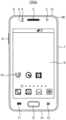
도 2b를 참조하면, 전자 장치(1000a)는 전면카메라(2), 스피커(3), 근접센서(4), 조도센서(5), USB(universal serial bus) 인터페이스(6), 전원 버튼(7), 볼륨조절 버튼(8), 디스플레이 및 터치스크린(9), 아이콘(10), 메뉴버튼(11), 홈 버튼(12), 취소버튼(13), 마이크(14), 오디오 출력 인터페이스(15) 및 안테나(16)를 포함할 수 있다.Referring to FIG. 2B, the
전면카메라(2)는 터치스크린(9) 방향의 카메라로 영상통화 또는 카메라의 용도로 사용된다. 스피커(3)는 사용자가 터치스크린(9)의 아이콘(10)을 터치하거나 음성으로 입력신호를 보내어 멀티미디어 데이터를 재생할 경우, 전화교환망을 통해 다른 사용자와 통화를 할 경우 또는 전자 장치(1000a)의 조작음이나 알림음을 재생할 경우 오디오 데이터를 출력한다. 근접센서(4)는 사용자가 전화통화를 하기 위해 전자 장치(1000a)를 귀에 가까이 할 경우 전력소모를 줄이면서 의도하지 않은 터치로 인한 잘못된 동작을 방지하기 위해 디스플레이 및 터치 스크린(9)을 오프여부를 제어하기 위한 센서이다. 조도 센서(5)는 전자 장치(1000a) 주변으로부터 입사되는 빛의 양에 따라 디스플레이 및 터치 스크린(9)과 전면카메라(2)의 동작을 제어한다. USB 인터페이스(6)는 전자 장치(1000a)와 외부와 데이터 통신 및 전원공급을 받기 위한 입출력 인터페이스이다.The
전원버튼(7)은 전자 장치(1000a)의 전원을 온오프하거나, 디스플레이 및 터치스크린(9)의 화면을 온오프할 수 있고, 볼륨조절 버튼(8)은 스피커(3)의 오디오 출력을 제어할 수 있다. 아이콘(10)은 각각의 기능에 따라 디스플레이 및 터치스크린(9)에 복수의 아이콘들(10)이 위치할 수 있다. 예를 들어, 사용자는 멀티미디어 데이터를 재생하기 위하여 아이콘(10)을 터치할 수 있다.The power button 7 can turn on/off the power of the
메뉴버튼(11)은 아이콘들을 포함한 메뉴 및 설정메뉴를 열람하게 할 수 있고, 홈버튼(12)은 디스플레이 및 터치스크린(9)에서 전자 장치(1000a)가 소정의 동작을 수행하고 있는 도중에도 멀티워킹(multi-working)을 위해 홈 화면을 보여줄 수 있다. 취소버튼(13)은 전자 장치(1000a)가 소정의 동작 수행 중에 상기 동작을 취소하고 이전의 화면으로 되돌아 가기 위한 버튼이다.The
마이크(14)는 음성통화 또는 음성입력 신호를 위한 입출력 인터페이스이고, 오디오 출력 인터페이스(15), 예를 들면 이어폰 꽂이는 재생되는 멀티미디어 데이터의 오디오 출력을 위한 것이다. 도시하지는 않았으나, 오디오 출력 및 마이크 입력은 블루투스(Bluetooth) 등의 장치를 통해서도 인터페이스 될 수 있다. 안테나(16)는 디지털미디어 방송 서비스의 수신에 이용될 수 있다.The
전자 장치(1000a)의 상기 각 구성요소의 구체적인 실시예는 당업자에게 실현 가능한 범위에서 다양하게 구현될 수 있으며, 본 발명의 실시예들에 부합하는 범위 내에서 일부 구성요소는 생략되거나 다른 구성요소로 대체될 수 있다.Specific embodiments of each of the components of the
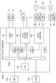
도 3은 본 발명의 실시예들에 따른 애플리케이션 프로세서를 나타내는 블록도이다.3 is a block diagram illustrating an application processor according to embodiments of the present invention.
도 3을 참조하면, 애플리케이션 프로세서(2000)는 시스템 버스(system bus)(SYSBUS)(2100), 호스트 프로세서(CPU)(100), 보이스 트리거 시스템(200), 오디오 서브 시스템(300) 및 센서 허브(400)를 포함할 수 있다. 오디오 서브 시스템(300) 및 센서 허브(400)는 도 2a의 오디오 처리 시스템(250)에 포함될 수 있다. 실시예들에 따라서, 애플리케이션 프로세서(2000)는 액티브 파워 관리부(active power manager)(APM), 메일 박스 모듈(mailbox module)들(MBXa, MBXb, MBXc) 및 인터럽트 콘트롤러(interrupt controller)(ITRC)를 더 포함할 수 있다.Referring to FIG. 3, an
시스템 버스(2100)는 인터커넥트 장치(interconnect) 또는 백본(backbone)이라 지칭할 수도 있다. 시스템 버스(2100)는 상위 계층의 버스, 하위 계층의 버스 및 이들을 연결하는 브리지를 포함하여 구현될 수 있다. 예를 들어, 시스템 버스(2100)는 AXI(advanced extensible interface), AHB(advanced high-performance bus), APB(advanced peripheral bus)와 같은 AMBA(advanced microcontroller bus architecture), 그 외의 다른 다양한 버스를 포함할 수 있으며, 이들을 연결하는 브리지를 포함할 수 있다. 호스트 프로세서(100)는 시스템 버스(2100)를 통하여 외부의 메모리 장치(1200) 및/또는 저장 장치(1300)에 액세스할 수 있다. 또한, 호스트 프로세서(100)는 시스템 버스(2100)를 통하여 보이스 트리거 시스템(200), 오디오 서브 시스템(300), 센서 허브(400)와 교신할 수 있다.The
도 3에는 편의상 하나의 인터럽트 콘트롤러(ITRC)를 도시하였으나, 인터럽트 콘트롤러(ITRC)는 적어도 하나의 GIC(general interrupt controller), 적어도 하나의 VIC(vectored interrupt controller) 등을 포함할 수 있다. 예를 들어, 인터럽트 콘트롤러(ITRC)는 프로그램 가능 인터럽트 콘트롤러(PIC, programmable interrupt controller)일 수 있다. 프로그램 가능 인터럽트 콘트롤러는 일반적으로 복수의 계층으로 이루어지며, 벡터로 표시되는 우선 순위 체제를 가진 콘트롤러일 수 있다. 프로그램 가능 인터럽트 콘트롤러는 주변 장치로부터 인터럽트 신호를 받아 우선 순위 문제를 해결하고, 인터럽트 처리 루틴을 표시하는 포인터 주소와 함께 프로세서, 제어기 등에 인터럽트를 요청할 수 있다.Although FIG. 3 illustrates one interrupt controller (ITRC) for convenience, the interrupt controller (ITRC) may include at least one general interrupt controller (GIC), at least one vectored interrupt controller (VIC), and the like. For example, the interrupt controller (ITRC) may be a programmable interrupt controller (PIC). Programmable interrupt controllers are generally multi-layered and can be controllers with priority regimes represented by vectors. The programmable interrupt controller can receive an interrupt signal from a peripheral device, solve a priority problem, and request an interrupt to a processor, controller, etc. with a pointer address indicating an interrupt handling routine.
액티브 파워 관리부(APM)는 애플리케이션 프로세서(2000)의 전원을 관리할 수 있다. 액티브 파워 관리부(APM)는 애플리케이션 프로세서(2000)의 각 영역 또는 각 기능 블록에 공급되는 파워를 관리할 수 있다. 메일 박스 모듈들(MBXa, MBXb, MBXc)은 애플리케이션 프로세서(2000)의 구성 요소들 사이의 데이터 전송 또는 애플리케이션 프로세서(2000)와 외부 장치 사이의 데이터 전송의 동기화를 지원할 수 있다. 메일 박스 모듈들(MBXa, MBXb, MBXc)에 대해서는 도 6을 참조하여 후술한다.The active power management unit (APM) may manage power of the
도 3에서는 보이스 트리거 시스템(200)과 오디오 서브 시스템(300)이 1개의 메일 박스 모듈(MBXc)을 통해 연결되고 보이스 트리거 시스템(200)과 센서 허브(400)가 2개의 메일 박스 모듈들(MBXa, MBXb) 및 액티브 파워 관리부(APM)를 통해 연결되는 것으로 도시하였으나, 실시예에 따라서 보이스 트리거 시스템(200)과 오디오 서브 시스템(300)이 2개의 메일 박스 모듈들 및 액티브 파워 관리부를 통해 연결되거나 보이스 트리거 시스템(200)과 센서 허브(400)가 1개의 메일 박스 모듈을 통해 연결될 수도 있다.3, the
보이스 트리거 시스템(200)은 시스템 버스(2100)에 전기적으로 연결되고 트리거 인터페이스를 통하여 제공되는 트리거 입력 신호에 기초하여 보이스 트리거 동작을 수행할 수 있다. 일 실시예에서, 보이스 트리거 시스템(200)은 디지털 마이크(digital microphone)(DMIC)(40) 및/또는 오디오 코덱(audio coder and decoder)(CODEC)(50)으로부터 상기 트리거 입력 신호를 수신할 수 있다. 즉, 보이스 트리거 시스템(200)의 상기 트리거 인터페이스는 디지털 마이크(40) 및 오디오 코덱(50)에 직접 연결될 수 있다. 오디오 코덱(50)은 디지털 마이크(40) 또는 아날로그 마이크(analog microphone)(AMIC)(61)로부터 입력되는 오디오 신호 및 스피커(62)로 출력되는 오디오 신호에 대한 인코딩 및 디코딩(또는, 아날로그-디지털 변환(ADC, analog-to-digital conversion) 및 디지털-아날로그 변환(DAC, digital-to-analog conversion))을 수행할 수 있다. 디지털 마이크(40)는 전자 장치의 보드 상에 애플리케이션 프로세서(2000)와 함께 실장되는 온-보드 마이크(on-board microphone)일 수 있다. 아날로그 마이크(61) 및 스피커(62)는 오디오 코덱(50)의 단자에 전기적으로 탈부착 가능한 장치일 수 있다.The
오디오 서브 시스템(300)은 시스템 버스(2100)에 전기적으로 연결되고 오디오 인터페이스를 통하여 재생 및 녹음되는 오디오 스트림을 처리하고 상기 오디오 인터페이스 및 메모리 장치(1200) 사이의 상기 오디오 스트림의 전송을 지원할 수 있다. 일 실시예에서, 오디오 서브 시스템(300)은 오디오 코덱(50) 및/또는 블루투스 모듈(Bluetooth module)(BTM)(70)과 상기 오디오 스트림을 교환할 수 있다. 다시 말해, 오디오 서브 시스템(300)의 상기 오디오 인터페이스는 오디오 코덱(50) 및 블루투스 모듈(BTM), USB 모듈에 직접 연결될 수 있다. 블루투스 모듈(70)은 블루투스 오디오 모듈(BTAUD)(80)을 통하여 블루투스 마이크(Bluetooth microphone)(BMIC)(81) 및 블루투스 스피커(82)와 연결되며, 블루투스 마이크(81)로부터 오디오 신호를 입력받거나 블루투스 스피커(82)로 오디오 신호를 출력할 수 있다. 실시예에 따라서, 블루투스 모듈(70)은 임의의 블루투스 장치(85)와 직접 연결될 수도 있다. 한편, 도 3에 도시하지는 않았으나, 오디오 서브 시스템(300)은 USB 모듈에 연결되어 상기 USB 모듈과 상기 오디오 스트림을 교환할 수도 있다.The
센서 허브(400)는 시스템 버스(2100)에 전기적으로 연결되고 하나 이상의 센서들(SEN1, SEN2)(31, 32)로부터 제공되는 감지 신호를 처리할 수 있다. 예를 들어, 센서 허브(400)는 센서들(31, 32)로부터의 신호들에 기초하여 전자 장치와 관련된 물리적 양을 측정하거나 동작 상태를 검출하고, 측정되거나 검출된 정보를 처리할 수 있다. 예를 들어, 센서들(31, 32)은 모션 센서(motion sensor), 자이로 센서(gyro sensor), 대기압 센서, 자기 센서, 가속도 센서, 그립(grip) 센서, 근접 센서, 생체 센서, 온도/습도 센서, 조도(illumination) 센서, 자외선(ultra violet, UV) 센서, 전기 코(electro-nose, E-nose) 센서, 근전도 (electromyography, EMG) 센서, 뇌파도 (electroencephalogram, EEG) 센서, 심전도(electrocardiogram, ECG) 센서, 적외선(infrared, IR) 센서, 홍채 센서, 지문 센서 중 적어도 하나를 포함할 수 있으며, 이에 한정되는 것은 아니다.The
일 실시예에서, 도 3에 도시된 바와 같이, 시스템 버스(2100), 보이스 트리거 시스템(200), 오디오 서브 시스템(300) 및 센서 허브(400)는 하나의 반도체 칩으로서 애플리케이션 프로세서(2000)에 함께 집적될 수 있다. 다른 실시예에서, 시스템 버스(2100), 보이스 트리거 시스템(200) 및 오디오 서브 시스템(300)은 하나의 반도체 칩으로서 애플리케이션 프로세서(2000)에 함께 집적되고, 센서 허브(400)는 애플리케이션 프로세서(2000)의 외부에 구현될 수 있다. 이와 같이, 본 발명의 실시예들에 따른 애플리케이션 프로세서, 이를 포함하는 전자 장치 및 그 동작 방법은, 보이스 트리거 시스템을 애플리케이션 프로세서에 함께 집적함으로써 보이스 트리거 동작과 관련된 기능을 저전력으로 그리고 효율적으로 구현할 수 있다.In one embodiment, as shown in FIG. 3 , the
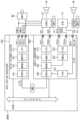
도 4는 본 발명의 실시예들에 따른 애플리케이션 프로세서의 보이스 트리거 시스템 및 오디오 서브 시스템의 연결 관계를 나타내는 블록도이다. 도 4에는 편의상 도 3에 도시된 호스트 프로세서(100) 등은 그 도시를 생략하였다. 이하 도 3과 중복되는 설명은 생략될 수 있다.4 is a block diagram illustrating a connection relationship between a voice trigger system and an audio sub system of an application processor according to embodiments of the present invention. In FIG. 4, for convenience, the
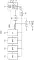
도 4를 참조하면, 애플리케이션 프로세서(2001)는 시스템 버스(2100), 보이스 트리거 시스템(201), 인터럽트 패드(PDITR), 오디오 서브 시스템(301) 및 메일 박스 모듈(MBX)을 포함할 수 있다. 오디오 서브 시스템(301)은 도 2a의 오디오 처리 시스템(250)에 포함될 수 있다.Referring to FIG. 4 , an
보이스 트리거 시스템(201)은 시스템 버스(2100)에 전기적으로 연결되고 트리거 인터페이스(TIF)를 통하여 제공되는 트리거 입력 신호(SDMIC, SAMIC)에 기초하여 보이스 트리거 동작을 수행할 수 있다. 보이스 트리거 시스템(201)은 디지털 마이크(40)로부터 트리거 입력 신호(SDMIC)를 수신하거나 오디오 코덱(50)으로부터 트리거 입력 신호(SAMIC)를 수신할 수 있다. 신호 전송의 동기화를 위해 마이크 클록 신호(MICCLK)가 보이스 트리거 시스템(201), 디지털 마이크(40) 및 오디오 코덱(50) 사이에서 전송될 수 있다. 트리거 입력 신호(SDMIC, SAMIC) 및 마이크 클록 신호(MICCLK)는 패드들(PD11, PD12, PD13)을 통하여 전송될 수 있다. 패드들(PD11, PD12, PD13)은 사용되지 않는 다른 패드들로부터 간섭을 받지 않도록 설정될 수 있다.The
인터럽트 패드(PDITR)는 인터럽트 신호(SITR)를 수신한다. 인터럽트 패드(PDITR)는 패드들(PD11, PD12, PD13) 및 패드들(PD21, PD22)과 별개로 형성될 수 있다. 예를 들어, 인터럽트 신호(SITR)는 도 4에 도시된 것처럼 디지털 마이크(40)로부터 수신될 수도 있고, 도 8, 9 및 10을 참조하여 후술하는 것처럼 블루투스 모듈, USB 모듈 또는 임의의 센서로부터 수신될 수도 있다.The interrupt pad PDITR receives the interrupt signal SITR. The interrupt pad PDITR may be formed separately from the pads PD11 , PD12 , and PD13 and the pads PD21 and PD22 . For example, the interrupt signal SITR may be received from the
인터럽트 신호(SITR)는 제1 인터럽트 신호 및 제2 인터럽트 신호를 포함한다. 인터럽트 패드(PDITR)는 상기 사일런스 환경에서 상기 노이즈 환경으로 변경되는 시점에서 상기 제1 인터럽트 신호를 수신하고, 상기 노이즈 환경에서 상기 사일런스 환경으로 변경되는 시점에서 상기 제2 인터럽트 신호를 수신한다. 상기 제1 인터럽트 신호가 수신된 경우에, 상기 보이스 트리거 동작을 수행하도록 보이스 트리거 시스템(201) 중 상기 유휴 상태인 적어도 일부를 상기 정상 상태로 전환한다. 상기 제2 인터럽트 신호가 수신된 경우에, 상기 보이스 트리거 동작을 수행하지 않도록 보이스 트리거 시스템(201) 중 적어도 일부를 상기 정상 상태에서 상기 유휴 상태로 전환하며, 이에 따라 파워 소모량을 더욱 감소시킬 수 있다.The interrupt signal SITR includes a first interrupt signal and a second interrupt signal. The interrupt pad PDITR receives the first interrupt signal when the silence environment changes to the noise environment, and receives the second interrupt signal when the noise environment changes to the silence environment. When the first interrupt signal is received, at least a part of the
보이스 트리거 시스템(201)은 트리거 인터페이스 회로(VTS interface circuit)(IFV)(211), 래퍼(wrapper)(WRPP)(221), 트리거 메모리(VTS memory)(MEMV)(231), 트리거 프로세서(VTS processor)(PRCV)(241), 인터럽트 콘트롤러(ITRC)(251) 및 얼라이브 블록(alive block)(ABLK)을 포함할 수 있다.The
트리거 인터페이스 회로(211)는 패드들(PD11, PD12, PD13)과 함께 트리거 인터페이스(TIF)를 형성하고 디지털 마이크(40) 또는 오디오 코덱(50)으로부터 제공되는 트리거 입력 신호(SDMIC, SAMIC)를 샘플링하고 샘플링된 데이터를 변환할 수 있다. 래퍼(221)는 트리거 인터페이스 회로(211)에 의해 변환된 데이터를 트리거 메모리(231)에 저장할 수 있다. 래퍼(221)는 트리거 메모리(231)에 일정 데이터를 저장하면 트리거 프로세서(241)로 인터럽트를 발생하고, 인터럽트 발생시 트리거 프로세서(241)는 트리거 메모리(231)에 저장된 데이터에 기초하여 상기 보이스 트리거 동작을 수행할 수 있다.The
일 실시예에서, 보이스 트리거 시스템(201)은 펄스 밀도 변조(PDM, pulse density modulation) 신호를 트리거 입력 신호(SDMIC, SAMIC)로서 수신하고, 트리거 인터페이스 회로(211)는 수신된 PDM 신호를 펄스 코드 변조(PCM, pulse code modulation) 데이터로 변환하고, 래퍼(221)는 PCM 데이터를 트리거 메모리(231)에 저장할 수 있다. 래퍼(221)는 직접 메모리 액세스 콘트롤러로 구현될 수도 있다.In one embodiment, the
얼라이브 블록(ABLK)은 시스템 버스(2100) 및 호스트 프로세서(100)의 액티브 모드 및 슬립 모드와 상관없이 항상 액티브 상태를 유지할 수 있다. 다시 말하면, 얼라이브 블록(ABLK)은 시스템 버스(2100) 및 호스트 프로세서(100)의 인에이블 및 디스에이블과 상관없이 항상 인에이블되어 있을 수 있다. 인터럽트 패드(PDITR)는 얼라이브 블록(ABLK) 내에 배치될 수 있다. 다시 말하면, 도 4의 실시예에서, 얼라이브 블록(ABLK) 및 인터럽트 패드(PDITR)는 보이스 트리거 시스템(201) 내에 배치될 수 있다.The alive block ABLK can always maintain an active state regardless of the active mode and sleep mode of the
인터럽트 콘트롤러(251)는 인터럽트 신호(SITR)를 트리거 프로세서(241)에 제공할 수 있으며, 트리거 프로세서(241)는 상기 제1 인터럽트 신호에 기초하여 상기 정상 상태로 진입하고 상기 제2 인터럽트 신호에 기초하여 상기 유휴 상태로 진입할 수 있다. 다시 말하면, 트리거 프로세서(241)는 상기 제1 및 제2 인터럽트 신호들에 기초하여 인에이블 및 디스에이블될 수 있다. 한편, 도 5를 참조하여 후술하는 것처럼, 트리거 프로세서(241)를 제외한 보이스 트리거 시스템(201)의 다른 구성요소들이 상기 제2 인터럽트 신호에 기초하여 추가적으로 상기 유휴 상태로 진입할 수도 있다.The interrupt
오디오 서브 시스템(301)은 시스템 버스(2100)에 전기적으로 연결되고 오디오 인터페이스(AIF)를 통하여 재생 및 녹음되는 오디오 스트림을 처리하고 상기 오디오 인터페이스 및 메모리 장치(1200) 사이의 상기 오디오 스트림의 전송을 지원할 수 있다. 일 실시예에서, 오디오 서브 시스템(301)은 오디오 코덱(50)과 상기 오디오 스트림을 교환할 수 있다. 오디오 서브 시스템(301)은 오디오 입력 패드(PD21)를 통하여 오디오 코덱(50)으로부터 오디오 입력 신호(SDI)를 수신하고 오디오 출력 패드(PD22)를 통하여 오디오 출력 신호(SDO)를 오디오 코덱(50)으로 전송할 수 있다.The
오디오 서브 시스템(301)은 오디오 인터페이스 회로(audio interface circuit)(IFA)(311), 직접 메모리 액세스 콘트롤러(direct access memory controller)(DMA)(321), 오디오 메모리(audio memory)(MEMA)(331) 및 오디오 프로세서(audio processor)(PRCA)(341)를 포함할 수 있다.The
오디오 인터페이스 회로(311)는 패드들(PD21, PD22)과 함께 오디오 인터페이스(AIF)를 형성하고 오디오 입력 신호(SDI) 및 오디오 출력 신호(SDO)를 통하여 상기 오디오 스트림을 송수신할 수 있다. 오디오 메모리(331)는 오디오 스트림의 데이터를 저장하고, 직접 메모리 액세스 콘트롤러(321)는 오디오 메모리(331)의 액세스, 즉 오디오 메모리(331)로부터의 데이터 독출 및 오디오 메모리(331)로의 데이터 기입을 제어할 수 있다. 오디오 프로세서(341)는 오디오 메모리(331)에 저장된 데이터를 처리할 수 있다.The
일 실시예에서, 오디오 인터페이스 회로(311)는 I2S 또는 IIS (Inter-IC Sound, Integrated Interchip Sound) 표준에 부합할 수 있다. 도 5에는 편의상 클록 신호에 대한 도시를 생략하였으나, 오디오 인터페이스 회로(311)는 I2S 표준에 따른 클록 신호에 기초하여 동작할 수 있다. 실시예에 따라서, 오디오 인터페이스 회로(311)는 디지털 마이크(40) 및/또는 오디오 코덱(50)에 직접 연결될 수도 있다.In one embodiment, the
도 5는 도 4의 애플리케이션 프로세서에 포함되는 보이스 트리거 시스템의 일 예를 나타내는 블록도이다. 이하 도 4와 중복되는 설명은 생략될 수 있다.FIG. 5 is a block diagram illustrating an example of a voice trigger system included in the application processor of FIG. 4 . A description overlapping with that of FIG. 4 may be omitted.
도 5를 참조하면, 보이스 트리거 시스템(201a)은 트리거 인터페이스 회로(211), 래퍼(221), 트리거 메모리(231), 트리거 프로세서(241) 및 인터럽트 콘트롤러(251)를 포함하며, 제1 RC 발진기(RCO1)(261), 클록 분배기(clock divider)(DIV)(271) 및 클록 게이팅 회로(clock gating circuit)(CG)(281)를 더 포함할 수 있다. 도 5에는 편의상 도 4에 도시된 패드들(PD11, PD12, PD13, PDITR) 및 얼라이브 블록(ABLK)은 그 도시를 생략하였다.Referring to FIG. 5, the
제1 RC 발진기(261)는 클록 신호(CLK)를 발생할 수 있다. 예를 들어, 제1 RC 발진기(261)는 보이스 트리거 시스템 내부 또는 외부의 얼라이브 블록(ABLK)에 포함될 수 있다. 클록 분배기(271)는 제1 RC 발진기(261)의 클록 신호(CLK)를 분배하여, 트리거 인터페이스(TIF)의 마이크 클록 신호(MICCLK)를 제공할 수 있다. 마이크 클록 신호(MICCLK)는 트리거 인터페이스 회로(211) 및 디지털 마이크(41)에 공급되어 트리거 인터페이스 회로(211) 및 디지털 마이크(41)를 구동하는데 이용될 수 있다.The
일 실시예에서, 디지털 마이크(41)는 스마트(smart) 디지털 마이크일 수 있고, 디지털 신호 프로세서(digital signal processor)(DSP)(42) 및 제2 RC 발진기(RCO2)(43)를 포함할 수 있다. 도 4의 디지털 마이크(40)와 유사하게, 디지털 마이크(41)로부터 트리거 입력 신호(SDMIC)가 수신되어 보이스 트리거 시스템(201a)에 제공될 수 있다. 또한, 디지털 신호 프로세서(42)는 상기 노이즈 환경을 감지하여 상기 제1 인터럽트 신호를 발생하고 상기 사일런스 환경을 감지하여 상기 제2 인터럽트 신호를 발생할 수 있다.In one embodiment, the
일 실시예에서, 인터럽트 콘트롤러(251)는 인터럽트 패드(PDITR)를 통해 수신된 인터럽트 신호(SITR)를 트리거 프로세서(241)에 제공하며, 트리거 인터페이스 회로(211), 래퍼(221) 및 트리거 메모리(231) 중 적어도 하나에 추가적으로 제공할 수 있다. 이에 따라, 상기 제1 인터럽트 신호에 기초하여 트리거 프로세서(241)가 상기 정상 상태로 전환될 수 있다. 또한, 상기 제2 인터럽트 신호에 기초하여 트리거 프로세서(241)가 상기 유휴 상태로 전환되며, 트리거 인터페이스 회로(211), 래퍼(221) 및 트리거 메모리(231) 중 적어도 하나가 추가적으로 상기 유휴 상태로 전환될 수 있다. 이 때, 트리거 메모리(231) 중 일부는 상기 유휴 상태로 전환된 이후에도 이전에 저장되었던 정보를 유지할 수 있다.In one embodiment, the interrupt
일 실시예에서, 인터럽트 콘트롤러(251)는 인터럽트 신호(SITR)를 클록 분배기(271) 및 클록 게이팅 회로(281) 중 적어도 하나에 추가적으로 제공할 수 있다. 상기 제2 인터럽트 신호가 클록 분배기(271)에 제공되는 경우에, 클록 분배기(271)는 제1 RC 발진기(261)의 클록 신호(CLK)를 추가적으로 분배하여 트리거 인터페이스 회로(211)에 공급함으로써, 다이나믹 파워(dynamic power)를 줄일 수 있다. 상기 제2 인터럽트 신호가 클록 게이팅 회로(281)에 제공되는 경우에, 클록 게이팅 회로(281)는 디지털 마이크(41)에 제공되는 마이크 클록 신호(MICCLK)를 차단함으로써(즉, 애플리케이션 프로세서는 마이크 클록 신호(MICCLK)를 발생하지 않음으로써), 마이크 클록 신호(MICCLK)를 보이스 트리거 시스템(201a)의 외부로 출력시키지 않을 수 있으며, 이에 따라 패드 토글 파워(pad toggle power)를 줄일 수 있다.In one embodiment, the interrupt
일 실시예에서, 상기 제2 인터럽트 신호를 기초로 클록 게이팅 회로(281)가 활성화되어 디지털 마이크(41)에 제공되는 마이크 클록 신호(MICCLK)가 차단된 경우에, 제2 RC 발진기(43)는 마이크 클록 신호(MICCLK)와 동일한 제2 마이크 클록 신호를 발생하며, 디지털 마이크(41)는 상기 제2 마이크 클록 신호에 기초하여 동작할 수 있다. 제2 RC 발진기(43)는 내부 또는 내장 RC 발진기로 부를 수 있다.In one embodiment, when the
한편, 디지털 신호 프로세서(42)는 상기 제2 인터럽트 신호를 발생한 이후에, 상기 노이즈 환경(또는 웨이크업(wake up) 환경)을 감지하여, 상기 제1 인터럽트 신호를 발생할 수 있다. 인터럽트 패드(PDITR)는 상기 제1 인터럽트 신호를 수신할 수 있고, 상기 제1 인터럽트 신호가 수신된 경우에, 상기 보이스 트리거 시스템 중 상기 유휴 상태로 전환된 적어도 일부를 다시 인에이블시킬 수 있다.Meanwhile, the
도 6은 도 4의 애플리케이션 프로세서에 포함되는 메일 박스 모듈의 일 실시예를 나타내는 도면이다.FIG. 6 is a diagram illustrating an embodiment of a mailbox module included in the application processor of FIG. 4 .
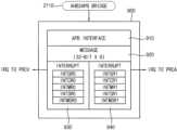
도 4 및 6을 참조하면, 애플리케이션 프로세서(2001)에 포함되는 메일 박스 모듈(MBX)은 보이스 트리거 시스템(201) 및 오디오 서브 시스템(301) 사이의 데이터 전송의 동기화를 지원할 수 있다. 애플리케이션 프로세서(2001)는 메일 박스 모듈(MBX)을 이용하여 시스템 버스(2100)와 독립적으로 보이스 트리거 시스템(201) 및 오디오 서브 시스템(301) 사이의 데이터 전송을 수행할 수 있다.Referring to FIGS. 4 and 6 , the mailbox module (MBX) included in the
도 6에 도시된 것처럼, 메일 박스 모듈(900)은 인터페이스(910), 메시지 박스(920), 복수의 레지스터들(INTGR0, INTCR0, INTMR0, INTSR0, INTMSR0)을 포함하는 제1 레지스터 회로(930) 및 복수의 레지스터들(INTGR1, INTCR1, INTMR1, INTSR1, INTMSR1)을 포함하는 제2 레지스터 회로(940)를 포함할 수 있다. 도 6에는 메일 박스 모듈(900)이 인터페이스(910)(예를 들어, APB 인터페이스)를 통하여 시스템 버스(2100)의 브리지, 예를 들어, AHB-APB 브리지(AHB2APB)에 연결되고, 메시지 박스(920)가 6*32 비트의 공유된 레지스터로 구현된 예가 도시되어 있으나, 이에 한정되는 것은 아니다. 인터페이스(910)의 타입, 메시지 박스(920)의 레지스터의 개수 및 비트수 등은 다양하게 변경될 수 있다. 제1 레지스터 회로(930)는 트리거 프로세서(PRCV)로의 인터럽트(IRQ TO PRCV)를 발행하고 제2 레지스터 회로(940)는 오디오 프로세서(PRCA)로의 인터럽트(IRQ TO PRCA)를 발행한다. 이러한 메일 박스 모듈(900)을 이용하여 보이스 트리거 시스템(201) 및 오디오 서브 시스템(301) 사이의 데이터 전송을 동기화할 수 있다.As shown in FIG. 6, the
트리거 프로세서(PRCV) 및 오디오 프로세서(PRCA) 중 하나가 메시지 박스(920)에 메시지를 기입한 후 인터럽트(IRQ)를 전송하는 방식으로 쌍방향 통신을 할 수 있으며, 폴링(polling) 방법 등을 통하여 적절하게 보이스 트리거 시스템(201) 및 오디오 서브 시스템(301) 사이의 데이터 전송의 동기화를 구현할 수 있다.After one of the trigger processor (PRCV) and the audio processor (PRCA) writes a message in the
한편, 실시예에 따라서, 보이스 트리거 시스템(201)이 상기 보이스 트리거 동작을 수행하지 않는 동안에, 오디오 서브 시스템(301)은 보이스 트리거 시스템(201)에 포함되는 트리거 메모리(231)의 적어도 일부를 캐시 메모리로 이용할 수도 있다.Meanwhile, according to an embodiment, while the
도 7, 8 및 9는 본 발명의 실시예들에 따른 애플리케이션 프로세서의 보이스 트리거 시스템 및 오디오 서브 시스템의 연결 관계를 나타내는 블록도들이다. 이하 도 4와 중복되는 설명은 생략될 수 있다.7, 8 and 9 are block diagrams illustrating a connection relationship between a voice trigger system of an application processor and an audio sub system according to embodiments of the present invention. A description overlapping with that of FIG. 4 may be omitted.
도 7을 참조하면, 애플리케이션 프로세서(2002)는 시스템 버스(2100), 보이스 트리거 시스템(202), 얼라이브 블록(ABLK), 인터럽트 패드(PDITR), 오디오 서브 시스템(301) 및 메일 박스 모듈(MBX)을 포함할 수 있다. 오디오 서브 시스템(301)은 도 2a의 오디오 처리 시스템(250)에 포함될 수 있다.Referring to FIG. 7, an
얼라이브 블록(ABLK) 및 얼라이브 블록(ABLK)에 포함되는 인터럽트 패드(PDITR)가 보이스 트리거 시스템(202)의 외부에 배치되는 것을 제외하면, 도 7의 애플리케이션 프로세서(2002)는 도 4의 애플리케이션 프로세서(2001)와 실질적으로 동일할 수 있다.Except for the fact that the alive block ABLK and the interrupt pad PDITR included in the alive block ABLK are disposed outside the
일 실시예에서, 얼라이브 블록(ABLK)은 애플리케이션 프로세서(2002) 내의 임의의 얼라이브 블록이며, 인터럽트 패드(PDITR)는 얼라이브 블록(ABLK)에 포함되는 GPIO(general purpose input/output) 패드일 수 있다.In one embodiment, the alive block ABLK is an arbitrary live block in the
도 8을 참조하면, 애플리케이션 프로세서(2003)는 시스템 버스(2100), 보이스 트리거 시스템(203), 인터럽트 패드(PDITR), 오디오 서브 시스템(303) 및 메일 박스 모듈(MBX)을 포함할 수 있다. 오디오 서브 시스템(303)은 도 2a의 오디오 처리 시스템(250)에 포함될 수 있다.Referring to FIG. 8 , an
블루투스 모듈(70)과 연결되기 위한 구조가 오디오 서브 시스템(303)에 추가되고, 인터럽트 신호(SITR)가 블루투스 모듈(70)로부터 제공되며, 이에 따라 얼라이브 블록(ABLK) 및 인터럽트 패드(PDITR)가 오디오 서브 시스템(303)에 배치되는 것을 제외하면, 도 8의 애플리케이션 프로세서(2003)는 도 4의 애플리케이션 프로세서(2001)와 실질적으로 동일할 수 있다.A structure for connecting with the
오디오 서브 시스템(303)은 시스템 버스(2100)에 전기적으로 연결되고 오디오 인터페이스를 통하여 재생 및 녹음되는 오디오 스트림을 처리하고 상기 오디오 인터페이스 및 메모리 장치(1200) 사이의 상기 오디오 스트림의 전송을 지원할 수 있다. 일 실시예에서, 오디오 서브 시스템(303)은 오디오 코덱(50) 및/또는 블루투스 모듈(70)과 상기 오디오 스트림을 교환할 수 있다. 오디오 서브 시스템(303)은 오디오 입력 패드(PD21)를 통하여 오디오 코덱(50)으로부터 오디오 입력 신호(SDI)를 수신하고 오디오 출력 패드(PD22)를 통하여 오디오 출력 신호(SDO)를 오디오 코덱(50)으로 전송할 수 있다. 오디오 서브 시스템(303)은 블루투스 입력 패드(PD23)를 통하여 블루투스 모듈(70)로부터 오디오 입력 신호(SDIB)를 수신하고 블루투스 출력 패드(PD24)를 통하여 오디오 출력 신호(SDOB)를 블루투스 모듈(70)로 전송할 수 있다.The
오디오 서브 시스템(303)은 제1 오디오 인터페이스 회로(IFA1)(313), 제1 직접 메모리 액세스 콘트롤러(DMA1)(323), 오디오 메모리(333), 오디오 프로세서(343), 제2 오디오 인터페이스 회로(IFA2)(353), 제2 직접 메모리 액세스 콘트롤러(DMA2)(363), 인터럽트 콘트롤러(ITRC)(370) 및 얼라이브 블록(ABLK)을 포함할 수 있다.The
인터럽트 패드(PDITR)는 얼라이브 블록(ABLK) 내에 배치될 수 있다. 다시 말하면, 도 8의 실시예에서, 얼라이브 블록(ABLK) 및 인터럽트 패드(PDITR)는 오디오 서브 시스템(303) 내에 배치될 수 있다.The interrupt pad PDITR may be disposed in the alive block ABLK. In other words, in the embodiment of FIG. 8 , the alive block ABLK and the interrupt pad PDITR may be disposed within the
도 4 및 5의 디지털 마이크(40, 41)와 유사하게, 블루투스 모듈(70)은 상기 사일런스 환경에서 상기 노이즈 환경으로 변경되는 시점에서 상기 제1 인터럽트 신호를 발생하고, 상기 노이즈 환경에서 상기 사일런스 환경으로 변경되는 시점에서 상기 제2 인터럽트 신호를 발생한다. 인터럽트 패드(PDITR)는 블루투스 모듈(70)로부터 상기 제1 및 제2 인터럽트 신호들을 포함하는 인터럽트 신호(SITR)를 수신할 수 있다. 다시 말하면, 도 8의 실시예에서, 인터럽트 패드(PDITR)는 블루투스 인터럽트 패드일 수 있다.Similar to the
인터럽트 콘트롤러(370)는 인터럽트 신호(SITR)를 오디오 프로세서(343)에 제공할 수 있으며, 오디오 프로세서(343)는 메일 박스 모듈(MBX)을 통하여 인터럽트 신호(SITR)를 트리거 프로세서(241)에 제공하여, 트리거 프로세서(241)를 상기 정상 상태로 전환하거나 상기 유휴 상태로 전환할 수 있다. 다시 말하면, 메일 박스 모듈(MBX)을 이용하여 시스템 버스(2100)와 독립적으로 보이스 트리거 시스템(203) 및 오디오 서브 시스템(303) 사이의 인터럽트 전송을 수행할 수 있다.The interrupt
도 9를 참조하면, 애플리케이션 프로세서(2004)는 시스템 버스(2100), 보이스 트리거 시스템(204), 인터럽트 패드(PDITR), 오디오 서브 시스템(304) 및 메일 박스 모듈(MBX)을 포함할 수 있다. 오디오 서브 시스템(304)은 도 2a의 오디오 처리 시스템(250)에 포함될 수 있다.Referring to FIG. 9 , an
오디오 코덱(50)과 연결되기 위한 구조가 오디오 서브 시스템(304)에서 제거되고, USB 모듈(90)과 연결되기 위한 구조가 오디오 서브 시스템(304)에 추가되고, 인터럽트 신호(SITR)가 USB 모듈(90)로부터 제공되며, 이에 따라 얼라이브 블록(ABLK) 및 인터럽트 패드(PDITR)가 오디오 서브 시스템(304)에 배치되는 것을 제외하면, 도 9의 애플리케이션 프로세서(2004)는 도 4의 애플리케이션 프로세서(2001)와 실질적으로 동일할 수 있다.A structure for connection with the
오디오 서브 시스템(304)은 시스템 버스(2100)에 전기적으로 연결되고 오디오 인터페이스를 통하여 재생 및 녹음되는 오디오 스트림을 처리하고 상기 오디오 인터페이스 및 메모리 장치(1200) 사이의 상기 오디오 스트림의 전송을 지원할 수 있다. 일 실시예에서, 오디오 서브 시스템(304)은 USB 모듈(90)과 상기 오디오 스트림을 교환할 수 있다. 오디오 서브 시스템(304)은 USB 입력 패드(PD25)를 통하여 USB 마이크(USB microphone)(UMIC)(91) 및 USB 모듈(90)로부터 오디오 입력 신호(SDIU)를 수신하고 USB 출력 패드(PD26)를 통하여 오디오 출력 신호(SDOU)를 USB 모듈(90) 및 USB 스피커(92)로 전송할 수 있다.The
오디오 서브 시스템(304)은 오디오 인터페이스 회로(314), 직접 메모리 액세스 콘트롤러(324), 오디오 메모리(334), 오디오 프로세서(344), 브릿지 버스(bridge bus)(BRDG)(354), 인터럽트 콘트롤러(370) 및 얼라이브 블록(ABLK)을 포함할 수 있다.The
인터럽트 패드(PDITR)는 얼라이브 블록(ABLK) 내에 배치될 수 있다. 다시 말하면, 도 9의 실시예에서, 얼라이브 블록(ABLK) 및 인터럽트 패드(PDITR)는 오디오 서브 시스템(304) 내에 배치될 수 있다.The interrupt pad PDITR may be disposed in the alive block ABLK. In other words, in the embodiment of FIG. 9 , the alive block ABLK and the interrupt pad PDITR may be disposed within the
도 4 및 5의 디지털 마이크(40, 41)와 유사하게, USB 모듈(90)은 상기 사일런스 환경에서 상기 노이즈 환경으로 변경되는 시점에서 상기 제1 인터럽트 신호를 발생하고, 상기 노이즈 환경에서 상기 사일런스 환경으로 변경되는 시점에서 상기 제2 인터럽트 신호를 발생한다. 인터럽트 패드(PDITR)는 USB 모듈(90)로부터 상기 제1 및 제2 인터럽트 신호들을 포함하는 인터럽트 신호(SITR)를 수신할 수 있다. 다시 말하면, 도 9의 실시예에서, 인터럽트 패드(PDITR)는 USB 인터럽트 패드일 수 있다.Similar to the
인터럽트 콘트롤러(370)는 인터럽트 신호(SITR)를 오디오 프로세서(344)에 제공할 수 있으며, 오디오 프로세서(344)는 메일 박스 모듈(MBX)을 통하여 인터럽트 신호(SITR)를 트리거 프로세서(241)에 제공하여, 트리거 프로세서(241)를 상기 정상 상태로 전환하거나 상기 유휴 상태로 전환할 수 있다. 다시 말하면, 메일 박스 모듈(MBX)을 이용하여 시스템 버스(2100)와 독립적으로 보이스 트리거 시스템(204) 및 오디오 서브 시스템(304) 사이의 인터럽트 전송을 수행할 수 있다.The interrupt
한편, 보이스 트리거 시스템(204)은 브릿지 버스(354)를 통하여 USB 모듈(90)로부터 상기 트리거 입력 신호를 수신할 수도 있다.Meanwhile, the
도시하지는 않았지만, 도 4 및 7의 실시예에서 오디오 코덱(50)이 오디오 서브 시스템(301)에 포함되도록 변경될 수도 있다. 도 8의 실시예는 오디오 코덱(50)과 관련된 구성이 제거되고 보이스 트리거 시스템(203)이 블루투스 모듈(70)로부터 상기 트리거 입력 신호를 수신하도록, 도 9의 실시예와 유사하게 변경될 수도 있다. 또한, 도 9의 실시예는 오디오 코덱(50)과 관련된 구성이 추가되고 보이스 트리거 시스템(204)이 오디오 코덱(50)으로부터 상기 트리거 입력 신호를 수신하도록, 도 8의 실시예와 유사하게 변경될 수도 있다.Although not shown, in the embodiments of FIGS. 4 and 7 , the
도 10은 본 발명의 실시예들에 따른 애플리케이션 프로세서의 보이스 트리거 시스템 및 센서 허브의 연결 관계를 나타내는 블록도이다. 도 10에는 편의상 도 3에 도시된 호스트 프로세서(100) 등은 그 도시를 생략하였다. 이하 도 4와 중복되는 설명은 생략될 수 있다.10 is a block diagram illustrating a connection relationship between a voice trigger system of an application processor and a sensor hub according to embodiments of the present invention. In FIG. 10, for convenience, the
도 10을 참조하면, 애플리케이션 프로세서(2005)는 시스템 버스(2100), 보이스 트리거 시스템(205), 센서 허브(405), 액티브 파워 관리부(APM) 및 메일 박스 모듈들(MBXa, MBXb)을 포함할 수 있다. 센서 허브(405)는 도 2a의 오디오 처리 시스템(250)에 포함될 수 있다.Referring to FIG. 10, an
보이스 트리거 시스템(205)은 시스템 버스(2100)에 전기적으로 연결되고 트리거 인터페이스를 통하여 제공되는 트리거 입력 신호(SDMIC)에 기초하여 보이스 트리거 동작을 수행할 수 있다. 보이스 트리거 시스템(205)은 디지털 마이크(40)로부터 트리거 입력 신호(SDMIC)를 수신할 수 있다. 신호 전송의 동기화를 위해 마이크 클록 신호(MICCLK)가 보이스 트리거 시스템(205) 및 디지털 마이크(40) 사이에서 전송될 수 있다.The
센서 허브(405)는 시스템 버스(2100)에 전기적으로 연결되고 오디오 인터페이스를 통하여 하나 이상의 센서들(SEN1, SEN2, SEN3)(31, 32, 33)로부터 제공되는 감지 신호들을 처리할 수 있다.The
센서 허브(405)는 센서 로직(sensor logic)(LOGS)(415), 센서 메모리(sensor memory)(MEMS)(425), 센서 프로세서(sensor processor)(PRCS)(435), 인터럽트 콘트롤러(ITRC)(440) 및 얼라이브 블록(ABLK)을 포함할 수 있고, 도 3을 참조하여 설명한 바와 같은 다양한 센서들로부터 제공되는 감지 신호들을 처리할 수 있다.The
인터럽트 패드(PDITR)는 얼라이브 블록(ABLK) 내에 배치될 수 있다. 다시 말하면, 도 10의 실시예에서, 얼라이브 블록(ABLK) 및 인터럽트 패드(PDITR)는 센서 허브(405) 내에 배치될 수 있다.The interrupt pad PDITR may be disposed in the alive block ABLK. In other words, in the embodiment of FIG. 10 , the alive block ABLK and the interrupt pad PDITR may be disposed within the
도 4 및 5의 디지털 마이크(40, 41)와 유사하게, 적어도 하나의 센서(예를 들어, 센서(33))는 상기 사일런스 환경에서 상기 노이즈 환경으로 변경되는 시점에서 상기 제1 인터럽트 신호를 발생하고, 상기 노이즈 환경에서 상기 사일런스 환경으로 변경되는 시점에서 상기 제2 인터럽트 신호를 발생한다. 인터럽트 패드(PDITR)는 센서(33)로부터 상기 제1 및 제2 인터럽트 신호들을 포함하는 인터럽트 신호(SITR)를 수신할 수 있다. 다시 말하면, 도 10의 실시예에서, 인터럽트 패드(PDITR)는 센서 인터럽트 패드일 수 있다.Similar to the
인터럽트 콘트롤러(440)는 인터럽트 신호(SITR)를 센서 프로세서(435)에 제공할 수 있으며, 센서 프로세서(435)는 메일 박스 모듈들(MBXa, MBXb)을 통하여 인터럽트 신호(SITR)를 트리거 프로세서(241)에 제공하여, 트리거 프로세서(241)를 상기 정상 상태로 전환하거나 상기 유휴 상태로 전환할 수 있다. 다시 말하면, 메일 박스 모듈들(MBXa, MBXb)을 이용하여 시스템 버스(2100)와 독립적으로 보이스 트리거 시스템(205) 및 센서 허브(405) 사이의 인터럽트 전송을 수행할 수 있다.The interrupt
일 실시예에서, 도 10에 도시된 것처럼, 2개의 메일 박스 모듈들(MBXa, MBXb)이 액티브 파워 관리부(APM)를 매개로 하여 보이스 트리거 시스템(205) 및 센서 허브(405) 사이의 데이터 전송의 동기화를 지원할 수 있다. 메일 박스 모듈들(MBXa, MBXb)은 도 6을 참조하여 설명한 바와 같다. 다른 실시예에서, 액티브 파워 관리부(APM)를 경유하지 않고 1개의 메일 박스 모듈이 보이스 트리거 시스템(205) 및 센서 허브(405) 사이의 데이터 전송의 동기화를 지원할 수 있다.In one embodiment, as shown in FIG. 10, two mailbox modules (MBXa, MBXb) transmit data between the
도시하지는 않았지만, 도 10의 실시예는 보이스 트리거 시스템(205)이 오디오 코덱(50)으로부터 트리거 입력 신호(SAMIC)를 수신하도록, 도 4의 실시예와 유사하게 변경될 수도 있다. 또한, 도시하지는 않았지만, 도 8, 9 및 10의 실시예는 얼라이브 블록(ABLK) 및 얼라이브 블록(ABLK)에 포함되는 인터럽트 패드(PDITR)가 오디오 서브 시스템(303, 304) 또는 센서 허브(405)의 외부에 배치되도록, 도 7의 실시예와 유사하게 변경될 수도 있다.Although not shown, the embodiment of FIG. 10 may be modified similarly to the embodiment of FIG. 4 such that the
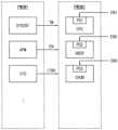
도 11a 및 11b는 본 발명의 실시예들에 따른 애플리케이션 프로세서의 파워 도메인을 설명하기 위한 도면들이다.11A and 11B are diagrams for explaining a power domain of an application processor according to embodiments of the present invention.
애플리케이션 프로세서는 서로 다른 파워들을 각각 공급받는 복수의 파워 도메인을 포함할 수 있고, 도 11a 및 11b에는 예시적으로 제1 파워 도메인(PWDM1) 및 제2 파워 도메인(PWDM2)이 도시되어 있다. 제1 파워 도메인(PWDM1)은 애플리케이션 프로세서의 액티브 모드 및 스탠바이 모드(또는 슬립 모드)에서 모두 전원이 공급되는 상시 파워 도메인(always-powered domain)이고, 제2 파워 도메인(PWDM2)는 스탠바이 모드에서 전원이 차단되는 파워 세이브 도메인(power-save domain)일 수 있다.The application processor may include a plurality of power domains each receiving different powers, and FIGS. 11A and 11B exemplarily show a first power domain PWDM1 and a second power domain PWDM2 . The first power domain PWDM1 is an always-powered domain in which power is supplied in both the active mode and standby mode (or sleep mode) of the application processor, and the second power domain PWDM2 is powered in the standby mode. This may be a blocked power-save domain.
도 11a를 참조하면, 상시 파워 도메인(PWDM1)에는 시스템 카운터(system counter)(SYSCNT), 액티브 파워 관리부(APM) 및 보이스 트리거 시스템(VTS)이 배치될 수 있다. 파워 세이브 도메인(PWDM2)에는 호스트 프로세서(CPU), 오디오 서브 시스템(ABOX), 센서 허브(CHUB) 등과 같은 복수의 하드웨어 블록들이 배치될 수 있다.Referring to FIG. 11A , a system counter (SYSCNT), an active power management unit (APM), and a voice trigger system (VTS) may be disposed in the regular power domain (PWDM1). A plurality of hardware blocks such as a host processor (CPU), an audio sub system (ABOX), a sensor hub (CHUB), and the like may be disposed in the power save domain (PWDM2).
시스템 카운터(SYSCNT)는 시간 정보(TM)를 발생하여 시스템의 전역에 제공할 수 있다. 액티브 파워 관리부(AMP)는 복수의 파워 인에이블 신호들(EN)을 발생하여 각 구성 요소의 파워의 공급 및 차단 등을 제어할 수 있다.The system counter (SYSCNT) can generate time information (TM) and provide it to the entire system. The active power management unit AMP may generate a plurality of power enable signals EN to control power supply and shutdown of each component.
본 발명에서 액티브 모드는 적어도 호스트 프로세서(CPU)가 인에이블되어 운영 체제(OS, operating system)가 동작(running)하는 모드를 나타내고, 슬립 모드는 호스트 프로세서(CPU)가 디스에이블되는 저전력 모드 또는 스탠바이 모드를 나타낸다.In the present invention, the active mode represents a mode in which at least the host processor (CPU) is enabled and the operating system (OS) runs, and the sleep mode is a low power mode or standby mode in which the host processor (CPU) is disabled. indicates the mode.
보이스 트리거 시스템(VTS)은 전술한 트리거 이벤트를 나타내는 인터럽트 신호(ITRR)를 발생할 수 있다.The voice trigger system (VTS) may generate an interrupt signal (ITRR) indicating the trigger event described above.
도 11a의 배치와 다르게, 도 11b에서와 같이 보이스 트리거 시스템(VTS)이 제2 파워 도메인(PWDM2)에 배치될 수도 있다.Unlike the arrangement of FIG. 11A, as shown in FIG. 11B, the voice trigger system (VTS) may be disposed in the second power domain (PWDM2).
도 11a 및 11b에 도시된 바와 같이, 호스트 프로세서(CPU), 보이스 트리거 시스템(VTS), 오디오 서브 시스템(ABOX) 및 센서 허브(CHUB)는 파워 게이팅 회로들(PG1~PG4)을 각각 포함할 수 있고, 파워 게이팅 회로들(PG1~PG4)은 파워 인에이블 신호들(EN1~EN4)에 응답하여 선택적으로 파워를 공급할 수 있다. 이와 같이, 보이스 트리거 시스템(VTS), 오디오 서브 시스템(ABOX) 및 센서 허브(CHUB)의 각각은 호스트 프로세서(CPU)와 독립적으로 파워 게이팅되어 호스트 프로세서(CPU)와 독립적으로 인에이블될 수 있다.As shown in FIGS. 11A and 11B , the host processor (CPU), voice trigger system (VTS), audio sub system (ABOX), and sensor hub (CHUB) may include power gating circuits PG1 to PG4, respectively. The power gating circuits PG1 to PG4 may selectively supply power in response to the power enable signals EN1 to EN4. As such, each of the voice trigger system (VTS), audio subsystem (ABOX), and sensor hub (CHUB) may be power gated independently of the host processor (CPU) and enabled independently of the host processor (CPU).
이상 설명한 바와 같이, 본 발명의 실시예들에 따른 애플리케이션 프로세서, 이를 포함하는 전자 장치 및 그 동작 방법은, 보이스 트리거 시스템을 애플리케이션 프로세서에 함께 집적함으로써 보이스 트리거 동작과 관련된 기능을 저전력으로 그리고 효율적으로 구현할 수 있으며, 특히 호스트 프로세서가 액티브 모드에서 수행하여야 할 동작을 온칩 보이스 트리거 시스템을 이용하여 대신 수행함으로써, 애플리케이션 프로세서를 포함하는 전자 장치의 전력 소모를 감소하고 성능을 향상시킬 수 있다.As described above, an application processor according to embodiments of the present invention, an electronic device including the same, and an operating method thereof can implement functions related to a voice trigger operation with low power and efficiently by integrating a voice trigger system with an application processor. In particular, power consumption of an electronic device including an application processor may be reduced and performance may be improved by using an on-chip voice trigger system to perform an operation to be performed by the host processor in an active mode instead.
또한, 사일런스 환경에서 노이즈 환경으로 변경되는 시점에서, 트리거 입력 신호를 수신하는 패드 및 오디오 입출력 패드와 별개로 형성되는 인터럽트 패드를 통하여 수신된 제1 인터럽트 신호에 기초하여, 보이스 트리거 시스템 중 유휴 상태인 적어도 일부를 정상 상태로 전환할 수 있다. 추가적으로, 노이즈 환경에서 사일런스 환경으로 변경되는 시점에서, 인터럽트 패드를 통하여 수신된 제2 인터럽트 신호에 기초하여 보이스 트리거 시스템 중 적어도 일부를 상기 정상 상태에서 상기 유휴 상태로 전환할 수 있다. 따라서, 전반적인 보이스 트리거 시스템의 전력 소모를 더욱 감소시킬 수 있다.In addition, at the time when the silence environment changes to the noise environment, based on the first interrupt signal received through the interrupt pad formed separately from the pad receiving the trigger input signal and the audio input/output pad, the idle state of the voice trigger system At least some of them can be converted to a steady state. Additionally, at a point in time when the noise environment is changed to the silence environment, at least a part of the voice trigger system may be switched from the normal state to the idle state based on the second interrupt signal received through the interrupt pad. Accordingly, power consumption of the overall voice trigger system can be further reduced.
본 발명의 실시예들은 보이스 트리거 기능을 지원하는 임의의 집적 회로, 전자 장치 및 시스템에 유용하게 이용될 수 있다. 예를 들어, 본 발명의 실시예들은 컴퓨터(computer), 노트북(laptop), 핸드폰(cellular), 스마트 폰(smart phone), MP3 플레이어, PDA(personal digital assistant), PMP(portable multimedia player), 디지털 TV, 디지털 카메라, 포터블 게임 콘솔(portable game console), 네비게이션(navigation) 기기, 웨어러블(wearable) 기기, IoT(internet of things) 기기, IoE(internet of everything) 기기, e-북(e-book), VR(virtual reality) 기기, AR(augmented reality) 기기 등과 같은 전자 기기에 더욱 유용하게 적용될 수 있다.Embodiments of the present invention may be advantageously used in any integrated circuit, electronic device, or system that supports voice trigger functionality. For example, embodiments of the present invention may be used in a computer, a laptop, a cellular phone, a smart phone, an MP3 player, a personal digital assistant (PDA), a portable multimedia player (PMP), a digital TV, digital camera, portable game console, navigation device, wearable device, IoT (internet of things) device, IoE (internet of everything) device, e-book , VR (virtual reality) devices, AR (augmented reality) devices and the like can be more usefully applied to electronic devices.
상기에서는 본 발명의 바람직한 실시예를 참조하여 설명하였지만, 해당 기술분야의 숙련된 당업자는 하기의 특허청구범위에 기재된 본 발명의 사상 및 영역으로부터 벗어나지 않는 범위 내에서 본 발명을 다양하게 수정 및 변경시킬 수 있음을 이해할 것이다.Although the above has been described with reference to preferred embodiments of the present invention, those skilled in the art can variously modify and change the present invention without departing from the spirit and scope of the present invention described in the claims below. you will understand that you can
Claims (10)
Translated fromKorean상기 시스템 버스에 전기적으로 연결된 호스트 프로세서;
상기 시스템 버스에 전기적으로 연결되고 트리거 인터페이스를 통하여 제공되는 트리거 입력 신호에 기초하여 보이스 트리거 동작을 수행하여 트리거 이벤트를 발생하는 보이스 트리거 시스템; 및
외부 환경의 음압이 기준 음압보다 낮은 사일런스(silence) 환경에서 상기 외부 환경의 음압이 상기 기준 음압보다 높거나 같은 노이즈(noisy) 환경으로 변경되는 시점에서 발생되는 제1 인터럽트 신호를 수신하는 인터럽트 패드를 포함하고,
상기 제1 인터럽트 신호가 수신된 경우에, 상기 보이스 트리거 동작을 수행하도록 상기 보이스 트리거 시스템 중 유휴(idle) 상태인 적어도 일부를 정상(normal) 상태로 전환하는 애플리케이션 프로세서.system bus;
a host processor electrically connected to the system bus;
a voice trigger system electrically connected to the system bus and generating a trigger event by performing a voice trigger operation based on a trigger input signal provided through a trigger interface; and
An interrupt pad for receiving a first interrupt signal generated at a point in time when the sound pressure of the external environment is changed from a silence environment in which the sound pressure of the external environment is lower than the reference sound pressure to a noise environment in which the sound pressure of the external environment is higher than or equal to the reference sound pressure. include,
When the first interrupt signal is received, the application processor for converting at least a part of the voice trigger system, which is in an idle state, to a normal state to perform the voice trigger operation.
상기 인터럽트 패드는 상기 노이즈 환경에서 상기 사일런스 환경으로 변경되는 시점에서 발생되는 제2 인터럽트 신호를 더 수신하고,
상기 제2 인터럽트 신호가 수신된 경우에, 상기 보이스 트리거 동작을 수행하지 않도록 상기 보이스 트리거 시스템 중 적어도 일부를 상기 정상 상태에서 상기 유휴 상태로 전환하는 것을 특징으로 하는 애플리케이션 프로세서.According to claim 1,
The interrupt pad further receives a second interrupt signal generated at a point in time when the noise environment is changed to the silence environment,
When the second interrupt signal is received, the application processor, characterized in that for switching at least a part of the voice trigger system from the normal state to the idle state so as not to perform the voice trigger operation.
상기 시스템 버스 및 상기 호스트 프로세서의 액티브(active) 모드 및 슬립(sleep) 모드와 상관없이 항상 액티브 상태를 유지하는 얼라이브(alive) 블록을 더 포함하며,
상기 인터럽트 패드는 상기 얼라이브 블록 내에 배치되는 것을 특징으로 하는 애플리케이션 프로세서.According to claim 2,
An alive block that always maintains an active state regardless of an active mode and a sleep mode of the system bus and the host processor;
The interrupt pad is an application processor, characterized in that arranged in the alive block.
상기 얼라이브 블록 및 상기 인터럽트 패드는 상기 보이스 트리거 시스템 내에 배치되는 것을 특징으로 하는 애플리케이션 프로세서.According to claim 3,
Wherein the alive block and the interrupt pad are disposed within the voice trigger system.
트리거 메모리;
상기 트리거 인터페이스를 형성하고 디지털 마이크로부터 제공되는 상기 트리거 입력 신호를 샘플링하고 변환하는 트리거 인터페이스 회로;
상기 트리거 인터페이스 회로에 의해 제공되는 데이터를 상기 트리거 메모리에 저장하는 래퍼; 및
상기 트리거 메모리에 저장된 데이터에 기초하여 상기 보이스 트리거 동작을 수행하는 트리거 프로세서를 포함하고,
상기 제1 인터럽트 신호가 수신된 경우에 상기 트리거 프로세서가 상기 유휴 상태에서 상기 정상 상태로 전환되며, 상기 제2 인터럽트 신호가 수신된 경우에 상기 트리거 프로세서가 상기 정상 상태에서 상기 유휴 상태로 전환되는 것을 특징으로 하는 애플리케이션 프로세서.The method of claim 2, wherein the voice trigger system,
trigger memory;
a trigger interface circuit forming the trigger interface and sampling and converting the trigger input signal provided from a digital microphone;
a wrapper for storing data provided by the trigger interface circuit in the trigger memory; and
A trigger processor for performing the voice trigger operation based on data stored in the trigger memory;
When the first interrupt signal is received, the trigger processor switches from the idle state to the normal state, and when the second interrupt signal is received, the trigger processor switches from the normal state to the idle state. characterized application processor.
상기 제2 인터럽트 신호가 수신된 경우에, 상기 트리거 메모리, 상기 트리거 인터페이스 회로 및 상기 래퍼 중 적어도 하나가 추가적으로 상기 유휴 상태로 전환되며,
상기 트리거 메모리 중 일부는 상기 유휴 상태로 전환된 이후에 이전 정보를 유지하는 것을 특징으로 하는 애플리케이션 프로세서.According to claim 5,
When the second interrupt signal is received, at least one of the trigger memory, the trigger interface circuit, and the wrapper is additionally switched to the idle state;
Some of the trigger memories retain previous information after being switched to the idle state.
클록 신호를 발생하는 RC 발진기를 더 포함하고,
상기 RC 발진기의 클록 신호를 분배하여 상기 트리거 인터페이스의 마이크 클록 신호를 제공하며,
상기 제2 인터럽트 신호가 수신된 경우에, 상기 RC 발진기의 클록 신호를 추가적으로 분배하고, 상기 RC 발진기의 클록 신호에 기초하여 상기 마이크 클록 신호를 발생하지 않는 것을 특징으로 하는 애플리케이션 프로세서.According to claim 5,
Further comprising an RC oscillator generating a clock signal;
Distributing the clock signal of the RC oscillator to provide a microphone clock signal of the trigger interface;
When the second interrupt signal is received, the application processor further distributes the clock signal of the RC oscillator and does not generate the microphone clock signal based on the clock signal of the RC oscillator.
적어도 하나의 오디오 입출력 장치를 포함하고,
상기 애플리케이션 프로세서는,
시스템 버스;
상기 시스템 버스에 전기적으로 연결된 호스트 프로세서;
상기 시스템 버스에 전기적으로 연결되고 트리거 인터페이스를 통하여 제공되는 트리거 입력 신호에 기초하여 보이스 트리거 동작을 수행하여 트리거 이벤트를 발생하는 보이스 트리거 시스템; 및
외부 환경의 음압이 기준 음압보다 낮은 사일런스(silence) 환경에서 상기 외부 환경의 음압이 상기 기준 음압보다 높거나 같은 노이즈(noisy) 환경으로 변경되는 시점에서 발생되는 제1 인터럽트 신호를 수신하는 인터럽트 패드를 포함하며,
상기 제1 인터럽트 신호가 수신된 경우에, 상기 보이스 트리거 동작을 수행하도록 상기 보이스 트리거 시스템 중 유휴(idle) 상태인 적어도 일부를 정상(normal) 상태로 전환하는 전자 장치.application processor; and
at least one audio input/output device;
The application processor,
system bus;
a host processor electrically connected to the system bus;
a voice trigger system electrically connected to the system bus and generating a trigger event by performing a voice trigger operation based on a trigger input signal provided through a trigger interface; and
An interrupt pad for receiving a first interrupt signal generated at a point in time when the sound pressure of the external environment is changed from a silence environment in which the sound pressure of the external environment is lower than the reference sound pressure to a noise environment in which the sound pressure of the external environment is higher than or equal to the reference sound pressure. contains,
When the first interrupt signal is received, the electronic device converts at least a part of the voice trigger system, which is in an idle state, to a normal state to perform the voice trigger operation.
상기 인터럽트 패드는 상기 노이즈 환경에서 상기 사일런스 환경으로 변경되는 시점에서 발생되는 제2 인터럽트 신호를 더 수신하고,
상기 제2 인터럽트 신호가 수신된 경우에, 상기 보이스 트리거 동작을 수행하지 않도록 상기 보이스 트리거 시스템 중 적어도 일부를 상기 정상 상태에서 상기 유휴 상태로 전환하는 것을 특징으로 하는 전자 장치.According to claim 8,
The interrupt pad further receives a second interrupt signal generated at a point in time when the noise environment is changed to the silence environment,
When the second interrupt signal is received, at least a part of the voice trigger system is switched from the normal state to the idle state so as not to perform the voice trigger operation.
외부 환경의 음압이 기준 음압보다 낮은 사일런스(silence) 환경에서 상기 외부 환경의 음압이 상기 기준 음압보다 높거나 같은 노이즈(noisy) 환경으로 변경되는 시점에서 상기 인터럽트 패드를 통하여 제1 인터럽트 신호를 수신하는 단계; 및
상기 제1 인터럽트 신호가 수신된 경우에, 상기 보이스 트리거 동작을 수행하도록 상기 보이스 트리거 시스템 중 유휴(idle) 상태인 적어도 일부를 정상(normal) 상태로 전환하는 단계를 포함하는 애플리케이션 프로세서의 동작 방법.In an application processor formed by integrating a system bus, a host processor electrically connected to the system bus, a voice trigger system, and an interrupt pad on a single semiconductor chip, a trigger input signal provided by the voice trigger system through a trigger interface Generating a trigger event by performing a voice trigger operation based on;
Receiving a first interrupt signal through the interrupt pad at a time when the sound pressure of the external environment changes from a silence environment in which the sound pressure of the external environment is lower than the reference sound pressure to a noise environment equal to or higher than the reference sound pressure step; and
and converting at least a part of the voice trigger system, which is in an idle state, to a normal state to perform the voice trigger operation when the first interrupt signal is received.
Priority Applications (4)
| Application Number | Priority Date | Filing Date | Title |
|---|---|---|---|
| KR1020180009519AKR102530391B1 (en) | 2018-01-25 | 2018-01-25 | Application processor including low power voice trigger system with external interrupt, electronic device including the same and method of operating the same |
| US16/193,029US10783887B2 (en) | 2018-01-25 | 2018-11-16 | Application processor including low power voice trigger system with external interrupt, electronic device including the same and method of operating the same |
| TW107142273ATWI800566B (en) | 2018-01-25 | 2018-11-27 | Application processor including low power voice trigger system with external interrupt, electronic device including the same and method of operating the same |
| CN201910030037.1ACN110083218B (en) | 2018-01-25 | 2019-01-14 | Application processor, electronic device, and method of operating an application processor |
Applications Claiming Priority (1)
| Application Number | Priority Date | Filing Date | Title |
|---|---|---|---|
| KR1020180009519AKR102530391B1 (en) | 2018-01-25 | 2018-01-25 | Application processor including low power voice trigger system with external interrupt, electronic device including the same and method of operating the same |
Publications (2)
| Publication Number | Publication Date |
|---|---|
| KR20190090609A KR20190090609A (en) | 2019-08-02 |
| KR102530391B1true KR102530391B1 (en) | 2023-05-09 |
Family
ID=67298741
Family Applications (1)
| Application Number | Title | Priority Date | Filing Date |
|---|---|---|---|
| KR1020180009519AActiveKR102530391B1 (en) | 2018-01-25 | 2018-01-25 | Application processor including low power voice trigger system with external interrupt, electronic device including the same and method of operating the same |
Country Status (4)
| Country | Link |
|---|---|
| US (1) | US10783887B2 (en) |
| KR (1) | KR102530391B1 (en) |
| CN (1) | CN110083218B (en) |
| TW (1) | TWI800566B (en) |
Families Citing this family (2)
| Publication number | Priority date | Publication date | Assignee | Title |
|---|---|---|---|---|
| US20220046019A1 (en)* | 2020-08-04 | 2022-02-10 | Juniper Networks, Inc. | Adding third party hardware to network devices |
| US12153534B2 (en)* | 2022-08-25 | 2024-11-26 | Nxp Usa, Inc. | Communications device |
Citations (1)
| Publication number | Priority date | Publication date | Assignee | Title |
|---|---|---|---|---|
| JP2012504251A (en) | 2008-09-16 | 2012-02-16 | パーソニクス ホールディングス インコーポレイテッド | Audio library and method |
Family Cites Families (14)
| Publication number | Priority date | Publication date | Assignee | Title |
|---|---|---|---|---|
| US7617386B2 (en) | 2007-04-17 | 2009-11-10 | Xmos Limited | Scheduling thread upon ready signal set when port transfers data on trigger time activation |
| US8612786B1 (en)* | 2010-09-24 | 2013-12-17 | Amazon Technologies, Inc. | Deep idle mode |
| JP5902068B2 (en) | 2012-08-22 | 2016-04-13 | シャープ株式会社 | Information processing apparatus and control method thereof |
| DE212014000045U1 (en) | 2013-02-07 | 2015-09-24 | Apple Inc. | Voice trigger for a digital assistant |
| US20140229644A1 (en) | 2013-02-12 | 2014-08-14 | Haran Thanigasalam | Method, apparatus, system for including interrupt functionality in sensor interconnects |
| US20140270259A1 (en)* | 2013-03-13 | 2014-09-18 | Aliphcom | Speech detection using low power microelectrical mechanical systems sensor |
| US20150112690A1 (en)* | 2013-10-22 | 2015-04-23 | Nvidia Corporation | Low power always-on voice trigger architecture |
| EP3084760A4 (en) | 2013-12-20 | 2017-08-16 | Intel Corporation | Transition from low power always listening mode to high power speech recognition mode |
| KR102018152B1 (en)* | 2014-03-31 | 2019-09-04 | 인텔 코포레이션 | Location aware power management scheme for always-on-always-listen voice recognition system |
| US9812126B2 (en) | 2014-11-28 | 2017-11-07 | Microsoft Technology Licensing, Llc | Device arbitration for listening devices |
| US9775113B2 (en)* | 2014-12-11 | 2017-09-26 | Mediatek Inc. | Voice wakeup detecting device with digital microphone and associated method |
| KR20170046958A (en) | 2015-10-22 | 2017-05-04 | 삼성전자주식회사 | Electronic apparatus and Method for executing function using speech recognition thereof |
| US11120063B2 (en)* | 2016-01-25 | 2021-09-14 | Sony Corporation | Information processing apparatus and information processing method |
| US10129510B2 (en) | 2016-02-18 | 2018-11-13 | Samsung Electronics Co., Ltd. | Initiating human-machine interaction based on visual attention |
- 2018
- 2018-01-25KRKR1020180009519Apatent/KR102530391B1/enactiveActive
- 2018-11-16USUS16/193,029patent/US10783887B2/enactiveActive
- 2018-11-27TWTW107142273Apatent/TWI800566B/enactive
- 2019
- 2019-01-14CNCN201910030037.1Apatent/CN110083218B/enactiveActive
Patent Citations (1)
| Publication number | Priority date | Publication date | Assignee | Title |
|---|---|---|---|---|
| JP2012504251A (en) | 2008-09-16 | 2012-02-16 | パーソニクス ホールディングス インコーポレイテッド | Audio library and method |
Also Published As
| Publication number | Publication date |
|---|---|
| US10783887B2 (en) | 2020-09-22 |
| KR20190090609A (en) | 2019-08-02 |
| US20190228768A1 (en) | 2019-07-25 |
| TW201933045A (en) | 2019-08-16 |
| CN110083218B (en) | 2024-09-03 |
| CN110083218A (en) | 2019-08-02 |
| TWI800566B (en) | 2023-05-01 |
Similar Documents
| Publication | Publication Date | Title |
|---|---|---|
| US11216399B2 (en) | Application processor for low power operation, electronic device including the same and method of operating the same | |
| KR102629424B1 (en) | Application processor including low power voice trigger system with security, electronic device including the same and method of operating the same | |
| US11256638B2 (en) | Application processor supporting interrupt during audio playback, electronic device including the same and method of operating the same | |
| KR102530391B1 (en) | Application processor including low power voice trigger system with external interrupt, electronic device including the same and method of operating the same | |
| KR102459920B1 (en) | Application processor supporting low power echo cancellation, electronic device including the same and method of operating the same | |
| US11803499B2 (en) | Method of operating audio subsystem for USB module, system-on-chip performing the same and method of operating system-on-chip using the same | |
| KR102629385B1 (en) | Application processor including low power voice trigger system with direct path for barge-in, electronic device including the same and method of operating the same |
Legal Events
| Date | Code | Title | Description |
|---|---|---|---|
| PA0109 | Patent application | Patent event code:PA01091R01D Comment text:Patent Application Patent event date:20180125 | |
| PG1501 | Laying open of application | ||
| A201 | Request for examination | ||
| PA0201 | Request for examination | Patent event code:PA02012R01D Patent event date:20210105 Comment text:Request for Examination of Application Patent event code:PA02011R01I Patent event date:20180125 Comment text:Patent Application | |
| E701 | Decision to grant or registration of patent right | ||
| PE0701 | Decision of registration | Patent event code:PE07011S01D Comment text:Decision to Grant Registration Patent event date:20230327 | |
| GRNT | Written decision to grant | ||
| PR0701 | Registration of establishment | Comment text:Registration of Establishment Patent event date:20230503 Patent event code:PR07011E01D | |
| PR1002 | Payment of registration fee | Payment date:20230504 End annual number:3 Start annual number:1 | |
| PG1601 | Publication of registration |