KR102529754B1 - Telephone distribution system capable of active circuit distribution - Google Patents
Telephone distribution system capable of active circuit distributionDownload PDFInfo
- Publication number
- KR102529754B1 KR102529754B1KR1020230019232AKR20230019232AKR102529754B1KR 102529754 B1KR102529754 B1KR 102529754B1KR 1020230019232 AKR1020230019232 AKR 1020230019232AKR 20230019232 AKR20230019232 AKR 20230019232AKR 102529754 B1KR102529754 B1KR 102529754B1
- Authority
- KR
- South Korea
- Prior art keywords
- active
- wiring board
- output port
- input
- digital
- Prior art date
- Legal status (The legal status is an assumption and is not a legal conclusion. Google has not performed a legal analysis and makes no representation as to the accuracy of the status listed.)
- Active
Links
Images


Classifications
- H—ELECTRICITY
- H04—ELECTRIC COMMUNICATION TECHNIQUE
- H04Q—SELECTING
- H04Q1/00—Details of selecting apparatus or arrangements
- H04Q1/02—Constructional details
- H04Q1/14—Distribution frames
- H—ELECTRICITY
- H04—ELECTRIC COMMUNICATION TECHNIQUE
- H04M—TELEPHONIC COMMUNICATION
- H04M3/00—Automatic or semi-automatic exchanges
- H04M3/005—Interface circuits for subscriber lines
- H—ELECTRICITY
- H04—ELECTRIC COMMUNICATION TECHNIQUE
- H04Q—SELECTING
- H04Q11/00—Selecting arrangements for multiplex systems
- H04Q11/0001—Selecting arrangements for multiplex systems using optical switching
- H04Q11/0062—Network aspects
- H04Q11/0071—Provisions for the electrical-optical layer interface
- H—ELECTRICITY
- H04—ELECTRIC COMMUNICATION TECHNIQUE
- H04Q—SELECTING
- H04Q11/00—Selecting arrangements for multiplex systems
- H04Q11/04—Selecting arrangements for multiplex systems for time-division multiplexing
- H04Q11/0421—Circuit arrangements therefor
Landscapes
- Engineering & Computer Science (AREA)
- Computer Networks & Wireless Communication (AREA)
- Signal Processing (AREA)
- Structure Of Telephone Exchanges (AREA)
Abstract
Translated fromKoreanDescription
Translated fromKorean본 발명은 통신 선로 시스템에 관한 것으로, 더욱 상세하게는 전화 회선을 전화기에 연결하는 전화 배선반 시스템에 관한 것이다.The present invention relates to a communication line system, and more particularly, to a telephone wiring board system for connecting a telephone line to a telephone.
배선반의 국어사전의 정의는 전화 교환국에서 전화 선로를 전화기에 연결하기 전에 우선 통제하기 위하여 달아 놓은 장치인데, 일반적으로는 데이터나 전화 등 제반 통신 선로를 제어하여 단말장치에 데이터나 음성 신호를 전달하는 장치의 의미로 사용된다.The definition of a wiring board in the Korean dictionary is a device installed at a telephone exchange office to control a telephone line before connecting it to a telephone. used in the sense of a device.
이러한 배선반 시스템은 규모가 큰 회사나 고층 아파트와 같이 다수의 단말장치가 있는 경우 주 배선반(Main Distribution Frame)이 복수 개의 중간 배선반(Intermediate Distribution Frame)에 연결되고, 중간 배선반이 각 단말장치에 연결되는 구조인 경우가 일반적이다.In this distribution box system, a main distribution frame is connected to a plurality of intermediate distribution frames and the intermediate distribution frame is connected to each terminal device when there are many terminal devices such as a large-scale company or a high-rise apartment. structure is common.
‘특허문헌 1’에 주 배선반과 중간 배선반으로 구성되는 종래의 배선반 시스템이 개시되어 있다. 도 1은 종래의 배선반 시스템의 구성도로서, 종래의 배선반 시스템은 주로 지하에 위치하는 주 배선반(1) 및 건물의 각 층에 위치하는 중간 배선반(2)으로 구성된다. 주 배선반(1)은 이더넷 등 데이터 통신에 관여하는 데이터 주 배선반(3)과 전화 통화에 관여하는 음성 주 배선반(4)을 포함하고, 중간 배선반(2)은 댁내에 데이터 통신을 제공하는 패치 패널(5)과 댁내에 전화 통화를 제공하는 110 블럭(6)을 포함하여, 음성 주 배선반(4)에서 110 블럭(6)까지는 25P, 100P와 같은 다대형 UTP 케이블을 통해 통화를 전달하고 110 블럭(6)에서 댁내 전화기(8-1)까지는 4P와 같은 소대형 UTP 케이블을 통해 통화를 전달한다."
그런데 종래의 전화 배선반 시스템에서는 도 2에 도시된 바와 같이 2개의 110 블럭(6)을 어떻게 결선하느냐에 따라 통화 전송 경로가 결정되기 때문에 고장이나 이사, 기타 여하한 사유로 회선을 변경하는 경우 작업자가 직접 110 블럭(6)에 접근하여 수동 점퍼 작업을 통해 결선을 변경해야 하고, 결선 변경이 반영된 점퍼 코드(전화 회선을 연결하기 위한 회선 점퍼 라인) 관리 대장{2개의 110 블럭(6)의 연결 상태, 즉 점퍼된 상태를 기록한 것}을 작성 및 보관하여야 하는 유지보수의 불편함이 있다.However, in the conventional telephone wiring board system, as shown in FIG. 2, a call transmission route is determined depending on how the two 110
도 3은 종래의 배선반 시스템에서 점퍼 코드 결선 초기(왼쪽)와 운영 중 상황(오른쪽)의 결선 사진으로, 혹여 점퍼 코드 관리 대장이 분실되거나 판독이 불가능해지는 경우 통화 회선의 결선 상태를 알 수 없어 점퍼 코드가 어디로 연결되었는지 일일이 확인해야 하기 때문에 막대한 시간과 인력이 요구되는 문제점이 있다.Figure 3 is a picture of the jumper code wiring in the beginning (left) and the operating situation (right) in the conventional wiring board system. Since it is necessary to check where the code is connected one by one, there is a problem that requires a lot of time and manpower.
또 위와 같은 점퍼 코드 관리나 수동 작업의 문제가 아니라 하더라도 종래의 배선반 시스템에서는 예비 통화 선로가 구비되어 있지 않아 주 통화 선로 장애 시 주 배선반(1)에 연결된 댁내 전화기(8-1) 전체의 통화가 불가능해지는 문제점이 있다.In addition, even if the jumper code management or manual work is not a problem as described above, the conventional wiring board system does not have a spare call line, so that when the main communication line fails, the entire house phone (8-1) connected to the main wiring board (1) can stop the call. There is a problem that makes it impossible.
본 발명은 위와 같은 문제점을 해결하기 위하여 안출된 것으로, 본 발명이 해결하고자 하는 과제는 원격에서 통화 회선 변경이 가능하고, 회선의 연결 상황의 파악이 가능하며, 예비 통화 선로 구비가 용이한 전화 배선반 시스템을 제공하는 것이다.The present invention has been made to solve the above problems, and the problem to be solved by the present invention is a telephone wiring board capable of remotely changing a call line, grasping the connection status of a line, and easily providing a spare call line. to provide the system.
본 발명에 따른 능동적 회선 분배가 가능한 전화 배선반 시스템은 능동형 주 배선반 및 능동형 중간 배선반으로 구성되는 전화 배선반 시스템으로서, 상기 능동형 주 배선반이 다수의 전화기로부터 신호를 받아 전화기를 상호 접속하는 교환기 및 통화 신호를 상기 능동형 중간 배선반에 전달하는 제1 능동형 110 블록으로 구성되고, 상기 제1 능동형 110 블록이 상기 교환기와 아날로그 신호를 송수신하는 아날로그 입출력 포트; 상기 아날로그 입출력 포트에 입력되는 아날로그 신호를 디지털 신호로 변환하면서 시분할 다중화하는 다중화 모듈; 상기 다중화 모듈의 디지털 출력 신호를 상기 능동형 중간 배선반에 출력하는 디지털 입출력 포트 및 상기 디지털 입출력 포트에서 입력되는 시분할된 디지털 신호를 아날로그 신호로 변환하면서 역다중화하는 역다중화 모듈로 구성되며, 상기 능동형 중간 배선반이 제2 능동형 110 블록을 포함하여 구성되고, 상기 제2 능동형 110 블록이 상기 능동형 주 배선반에서 전송되는 디지털 신호를 수신하는 디지털 입출력 포트; 상기 디지털 입출력 포트를 통해 전송되는 디지털 신호를 아날로그 신호로 변환하면서 역다중화하는 역다중화 모듈; 상기 전화기와 아날로그 신호를 송수신하는 아날로그 입출력 포트 및 상기 아날로그 입출력 포트에 입력되는 아날로그 신호를 디지털 신호로 변환하면서 시분할 다중화하는 다중화 모듈로 구성되는 것을 기술적 특징으로 한다.A telephone switchboard system capable of active line distribution according to the present invention is a telephone switchboard system composed of an active main switchboard and an active intermediate switchboard, wherein the active main switchboard receives signals from a plurality of telephones and transmits exchanges and call signals for interconnecting telephones. an analog input/output port composed of a first active 110 block transmitting to the active intermediate wiring board, and through which the first active 110 block transmits/receives an analog signal to and from the exchange; a multiplexing module for time division multiplexing while converting an analog signal input to the analog input/output port into a digital signal; It consists of a digital input/output port that outputs the digital output signal of the multiplexing module to the active intermediate wiring board and a demultiplexing module that converts and demultiplexes the time-division digital signal input from the digital input/output port into an analog signal, and the active intermediate wiring board a digital input/output port including the second
본 발명에 따른 능동적 회선 분배가 가능한 전화 배선반 시스템은 능동형 주 배선반과 능동형 중간 배선반을 전기적으로 제어함으로써 원격에서 댁내 전화기에 이르는 전화 회선을 설정할 수 있다.A telephone wiring board system capable of active line distribution according to the present invention can establish a telephone line from a remote location to a home telephone by electrically controlling the active main wiring board and the active intermediate wiring board.
또 능동형 주 배선반과 능동형 중간 배선반의 회선 연결 상황을 모니터링함으로써 실시간으로 통화 회선 연결 상황을 파악할 수 있고, 점퍼 코드 관리 대장을 유지할 필요가 없다.In addition, by monitoring the line connection status of the active main wiring board and the active intermediate wiring board, the call line connection status can be grasped in real time, and there is no need to maintain a jumper code management ledger.
또 예비 광케이블을 구비함으로써 주 광케이블에 장애가 발생 시 자동으로 실시간 복구가 가능하다.In addition, by providing a spare optical cable, real-time recovery is possible automatically when a failure occurs in the main optical cable.
도 1은 종래의 배선반 시스템의 구성도
도 2는 2개의 110 블럭이 점퍼 코드로 연결되어 통화 회선을 형성하는 개념도
도 3은 종래의 배선반 시스템에서 점퍼 코드 결선 초기와 운영 중 상황의 결선 사진
도 4는 본 발명에 따른 능동적 회선 분배가 가능한 전화 배선반 시스템의 구성도
도 5는 제1 능동형 110 블록의 내부 구성도
도 6은 제2 능동형 110 볼록의 내부 구성도
도 7은 다중화 및 역다중화에 의한 통화 회선의 임의 설정 원리도
도 8은 본 발명에 따른 능동적 회선 분배가 가능한 전화 배선반 시스템의 이중화 구성의 제1 실시형태
도 9는 본 발명에 따른 능동적 회선 분배가 가능한 전화 배선반 시스템의 이중화 구성의 제2 실시형태
도 10은 본 발명에 따른 능동적 회선 분배가 가능한 전화 배선반 시스템의 이중화 구성의 제2 실시형태에서 장애 발생 시 대응 원리도1 is a block diagram of a conventional wiring board system;
2 is a conceptual diagram in which two 110 blocks are connected with a jumper code to form a communication line
Figure 3 is a picture of the wiring of the jumper cord wiring initial and operating situation in the conventional wiring board system
4 is a block diagram of a telephone wiring board system capable of active line distribution according to the present invention.
5 is an internal configuration diagram of a first active 110 block
6 is an internal configuration diagram of a second
7 is a principle diagram of arbitrary setting of a call line by multiplexing and demultiplexing
8 is a first embodiment of a redundant configuration of a telephone wiring board system capable of active line distribution according to the present invention
9 is a second embodiment of a redundant configuration of a telephone wiring board system capable of active line distribution according to the present invention
10 is a principle diagram for responding to a failure in a second embodiment of a redundant configuration of a telephone wiring board system capable of active line distribution according to the present invention.
이하에서는 본 발명에 따른 능동적 회선 분배가 가능한 전화 배선반 시스템을 첨부된 도면을 참조하여 상세히 설명한다.Hereinafter, a telephone wiring board system capable of active line distribution according to the present invention will be described in detail with reference to the accompanying drawings.
도 4는 본 발명에 따른 능동적 회선 분배가 가능한 전화 배선반 시스템의 구성도로서, 본 발명에 따른 능동적 회선 분배가 가능한 전화 배선반 시스템은 능동형 주 배선반(100) 및 능동형 중간 배선반(200)으로 구성되어, 능동형 주 배선반(100)과 능동형 중간 배선반(200)을 연결하는 회선을 능동형 주 배선반(100)과 능동형 중간 배선반(200) 각각에 의해 임의로 선택 가능하다. 본 발명에서 주 배선반과 중간 배선반에 수식어로 붙는 ‘능동형’의 의미는 종래와 같이 음성 통화에 장애가 발생하는 경우 장애가 있는 회선의 점퍼 코드를 배선반의 다른 포트에 연결하는 방식의 물리적 포트 변경이 아니라, 전화 회선을 형성하는 입출력 포트의 전기적 선택이 가능하게 함으로써 이러한 입출력 포트의 전기적 선택에 따른 통화 회선의 장애 복구가 사람의 개입 없이 사전에 정해진 시나리오 또는 실시간 전화 회선 형성 및 테스트에 의해 능동적으로 수행 가능하다는 뜻이다.4 is a configuration diagram of a telephone wiring board system capable of active line distribution according to the present invention. The telephone wiring board system capable of active line distribution according to the present invention is composed of an active
따라서 종래에 배선반 시스템에 회선 변경이 필요할 때 작업자가 직접 배선반에 접근하여 수동으로 점퍼 코드를 변경하던 것을 원격에서 능동형 주 배선반(100)과 능동형 중간 배선반(200)을 제어함으로써 쉽게 수행할 수 있고, 능동형 주 배선반(100)과 능동형 중간 배선반(200)의 회선 연결 상황을 모니터링함으로써 실시간으로 점퍼된 상태, 즉 통화 회선 연결 상황을 파악할 수 있고, 점퍼 코드 관리 대장을 작성할 수 있다.Therefore, when a line change is required in the wiring board system in the prior art, the operator directly accesses the wiring board and manually changes the jumper code, but can be easily performed by remotely controlling the active
또 물리적인 포트 변경이 없기 때문에 위 도 3(b)와 같이 점퍼 코드가 뒤죽박죽으로 교차되는 상황이 발생되지 않고, 도 3(a)와 같은 최초의 정리된 결선 상태를 유지할 수 있다.In addition, since there is no physical port change, a situation in which jumper codes are jumbled and crossed as shown in FIG. 3(b) above does not occur, and the first organized wiring state as shown in FIG.
이하에서는 편의상 능동형 주 배선반(100)에서 능동형 중간 배선반(200)으로 신호가 전달되는 흐름을 따라 설명한다.Hereinafter, for convenience, a flow of signals transmitted from the active
능동형 주 배선반(100)은 교환기(110) 및 제1 능동형 110 블록(120)으로 구성되고, 피뢰탄기반(130)을 더 포함하여 구성될 수 있다.The active type
교환기(110)는 다수의 전화기로부터 신호를 받아 전화기를 상호 접속하는 구성요소로서, 공중 전화망(PSTN; public switched telephone network)에 연결된다.The
제1 능동형 110 블록(120)은 N개의 아날로그 입출력 포트와 M개의 디지털 입출력 포트{예를 들면, 능동형 주 배선반(100)이 각 능동형 중간 배선반(200)과 전화 회선을 형성하여야 하므로 M은 능동형 중간 배선반(200)의 개수가 될 수 있다. N은 본 발명에 따른 능동적 회선 분배가 가능한 전화 배선반 시스템에 허용되는 최대 동시 통화 회선 개수가 될 수 있다}를 구비하여, 아날로그 입출력 포트의 통화 신호를 디지털 입출력 포트를 통해 능동형 중간 배선반(200)에 전달함으로써, 특정 댁내 전화기까지 전화 회선을 연결하는 구성요소이다(N, M은 자연수). 제1 능동형 110 블록(120)이 특정 아날로그 입출력 포트와 특정 능동형 중간 배선반(200)의 조합을 임의로 설정할 수 있고, 특정 능동형 중간 배선반(200)에 전달되는 통화 신호를 임의의 타임슬롯에 배열하여 다중화할 수 있기 때문에 본 발명에서 점퍼 코드가 연결하는 입출력 포트를 변경하지 않고 통화 회선의 재설정이 가능해진다. 제1 능동형 110 블록(120)은 N개의 아날로그 입력 신호를 M개의 디지털 신호로 분할하면서 시분할하는 다중화 스위치의 기능을 수행한다 할 수 있다(추후 설명하겠지만 역다중화 스위치의 기능도 수행한다).The first active 110
도 5는 제1 능동형 110 블록의 내부 구성도로서, 제1 능동형 110 블록(120)은 아날로그 입출력 포트(121), 다중화 모듈(122), 디지털 입출력 포트(123) 및 역다중화 모듈(124)로 구성되고, 광입출력 포트(125), 전광변환 모듈(126)이 더 포함될 수 있다. 여기서 전광변환 모듈(126)과 광입출력 포트(125)는 디지털 입출력 포트(123)를 대체하여 제1 능동형 110 블록(120)에 포함될 수 있다.5 is an internal configuration diagram of the first
아날로그 입출력 포트(121)는 교환기(110)와 아날로그 신호를 송수신하는 인터페이스이다.The analog input/
다중화 모듈(122)은 아날로그 입출력 포트(121)에 입력되는 아날로그 신호를 디지털 신호로 변환하면서 시분할 다중화(time division multiplexing)하는 구성요소로서, 다중화 과정에서 각 아날로그 입출력 포트(121)의 신호를 임의의 타임 슬롯에 배치하여 특정 아날로그 입출력 포트(121)의 신호가 디지털 신호에 특정 순서로 변환 배치되도록 함으로써 역다중화 후 특정 순서에서 원하는 아날로그 신호가 추출되도록 할 수 있다.The
다중화 모듈(122)은 다단(multi stage) 구성을 취함으로써 매우 많은 수의 아날로그 전화 신호를 능동형 중간 배선반(200)을 거쳐 매우 많은 수의 댁내 전화기에 전달할 수 있다. 예를 들어, 제1 다중화 모듈이 64kbps로 32개의 타임 슬롯을 다중화하여 1차군(E1)을 형성하고, 제2 다중화 모듈이 76개의 1차군을 다중화하여 2차군(STM1)을 형성하도록 할 수 있다. 이렇게 수백 Mbps급으로 형성된 데이터는 일반 동선으로는 전송이 비효율적이기 때문에 광선로를 통해 능동형 중간 배선반(200)으로 전송되는 것이 바람직하다. 광입출력 포트(125), 전광변환 모듈(126)은 이러한 광전송을 위해 구비될 수 있다.The
디지털 입출력 포트(123)는 다중화 모듈(122)의 디지털 출력 신호를 능동형 중간 배선반(200)에 출력하는 디지털 신호 전송 인터페이스이다.The digital input/
역다중화 모듈(124)은 디지털 입출력 포트(123)에서 입력되는 시분할된 디지털 신호{능동형 중간 배선반(200)에서 전송된다}를 아날로그 신호로 변환하면서 역다중화하는 구성요소이다.The
광입출력 포트(125)는 광케이블을 이용하여 능동형 주 배선반(100)과 능동형 중간 배선반(200)을 연결하는 경우 구비되는 구성요소로서, 본 발명에 따른 능동적 회선 분배가 가능한 전화 배선반 시스템의 이중화 구성과 관련이 있다. 이와 관련하여서는 본 발명에 따른 능동적 회선 분배가 가능한 전화 배선반 시스템의 이중화 구성을 설명하면서 다시 한 번 언급하기로 한다.The optical input/
전광변환 모듈(126)은 다중화 모듈(122)에서 출력되는 전기 신호를 광신호로 변환하고, 능동형 중간 배선반(200)에서 전달되는 광신호를 전기 신호로 변환하는 구성요소로서, 다중화 모듈(122)에서 다중화된 데이터의 전송 시 광전송이 유리한 경우에 대비하여 구비될 수 있다. 다중화 모듈(122)의 출력이 전기 신호이므로 UTP 케이블 등으로 전송이 원활하다면 전광변환 모듈(126) 없이 다중화 모듈(122)의 출력 포트에 UTP 케이블 등이 연결되어 능동형 중간 배선반(200)으로 디지털 신호가 전달된다.The electro-
피뢰탄기반(130)은 교환기(110)의 전단에 구비되어 교환기(110) 및 그 후단의 장치들을 낙뢰나 서지로부터 보호하는 구성요소이다.The
능동형 중간 배선반(200)은 제2 능동형 110 블록(210)과 기타 필요 장치들을 포함하여 구성되는데, 가장 간단하게는 능동형 중간 배선반(200)이 제2 능동형 110 블록(210) 자체일 수 있다. 도 6은 제2 능동형 110 볼록의 내부 구성도로서, 제2 능동형 110 블록(210)은 디지털 입출력 포트(211), 역다중화 모듈(212), 아날로그 입출력 포트(213) 및 다중화 모듈(214)로 구성되고, 광입출력 포트(215), 전광변환 모듈(216)이 더 포함될 수 있다. 여기서도 광입출력 포트(215)와 전광변환 모듈(216)이 디지털 입출력 포트(211)를 대체하여 또는 디지털 입출력 포트(211)와 병행하여 제2 능동형 110 블록(210)에 포함될 수 있다.The active
디지털 입출력 포트(211)는 능동형 주 배선반(100)에서 전송되는 디지털 신호를 수신하는 디지털 신호 전송 인터페이스이다.The digital input/
역다중화 모듈(212)은 디지털 입출력 포트(211)를 통해 전송되는 디지털 신호를 아날로그 신호로 변환하면서 역다중화하는 구성요소이다.The
아날로그 입출력 포트(213)는 댁내 전화기와 아날로그 신호를 송수신하는 구성요소이다.The analog input/
다중화 모듈(214)은 아날로그 입출력 포트(213)에 입력되는 아날로그 신호(댁내 전화기에서 전송된다)를 디지털 신호로 변환하면서 시분할 다중화하는 구성요소로서, 각 아날로그 입출력 포트(213)의 신호를 임의의 타임 슬롯에 배치하여 특정 아날로그 입출력 포트(213)의 신호가 디지털 신호에 특정 순서로 변환 배치되도록 함으로써 역다중화 후 특정 순서에서 원하는 아날로그 신호가 추출되도록 한다. 제2 능동형 110 블록(210)을 구성하는 다중화 모듈(214)도 제1 능동형 110 블록(120)의 다중화 모듈(122)과 동일하게 다단 구성을 취할 수 있다.The
광입출력 포트(215)는 능동형 주 배선반(100)과 능동형 중간 배선반(200)을 광케이블로 연결하기 위한 인터페이스이고, 전광변환 모듈(216)은 능동형 주 배선반(100)에서 전송되는 광신호를 전기신호로 변환하고 다중화 모듈(214)에서 출력되는 전기 신호를 광신호로 또는 광신호를 전기 신호로 변환하는 구성요소로서, 디지털 입출력 포트(211)를 대체하여 또는 디지털 입출력 포트(211)와 병행하여 구비될 수 있다.The optical input/
앞서 언급하였지만, 본 발명에서 점퍼 코드의 연결을 변경하지 않고 통화 회선의 재설정이 가능한 이유 중 하나는 특정 능동형 중간 배선반(200)에 전달되는 통화 신호를 임의의 타임슬롯에 배열하여 다중화할 수 있기 때문이다. 즉, 다중화 과정에서 목적하는 댁내 전화기에 연결될 수 있는 데이터 배열이 가능하기 때문에 본 발명이 성립할 수 있는 것인데, 반대로 생각하면 다중화 과정에서는 아날로그 신호를 배열 조정 없이 순서대로 다중화하고 역다중화 과정에서 원하는 타임슬롯의 디지털 데이터가 댁내 전화기에 대응되도록 추출하는 것도 가능하다. 도 7은 이러한 다중화 및 역다중화에 의한 통화 회선의 임의 설정 원리를 도시한 것으로서, 도 7(a)와 같이 다중화 모듈(122)에서 통화 신호를 임의의 타임슬롯에 배열하여 다중화하여 댁내 전화기와 회선이 연결되도록 할 수도 있고, 도 7(b)와 같이 역다중화 모듈(124)에서 임의의 타임슬롯의 디지털 신호를 추출하여 댁내 전화기와 회선이 연결되도록 할 수도 있다As mentioned above, one of the reasons why the communication line can be reset without changing the connection of jumper codes in the present invention is that the communication signal transmitted to a specific active
이상으로 본 발명에 따른 능동적 회선 분배가 가능한 전화 배선반 시스템을 설명하였는데, 양방향 전화 통화가 가능하기 위해서는 능동형 중간 배선반(200)에서 능동형 주 배선반(100)으로도 신호가 전달되어야 하므로, 위 설명은 그 반대 방향으로 신호가 전달될 때에도 동일하게 적용된다.Above, the telephone wiring board system capable of active line distribution according to the present invention has been described. In order to enable a two-way telephone call, a signal must be transmitted from the active
다음으로, 본 발명에 따른 능동적 회선 분배가 가능한 전화 배선반 시스템의 이중화 구성에 대해 설명한다. 이중화 구성의 경우 채널 용량이 커야 유리하므로(특히 제2 실시형태) 디지털 입출력 포트(123) 대신 광입출력 포트(125)가 구비되는 것이 바람직하다.Next, a redundant configuration of a telephone wiring board system capable of active line distribution according to the present invention will be described. In the case of a dual configuration, since it is advantageous to have a large channel capacity (especially in the second embodiment), it is preferable that the optical input/
도 8은 본 발명에 따른 능동적 회선 분배가 가능한 전화 배선반 시스템의 이중화 구성의 제1 실시형태로서, P2P(peer to peer) 형태이다. 제1 실시형태에서는 능동형 주 배선반(100)의 제1 능동형 110 블록(120)의 광입출력 포트(125)와 능동형 중간 배선반(200)의 제2 능동형 110 블록(210)의 광입출력 포트(215)를 2개의 광케이블(300, 310)로 연결하여, 1개의 광케이블은 주 케이블(300)로 사용하고 다른 1개의 광케이블은 예비 케이블(310)로 사용한다. 즉, 회선 연결에 이상이 없을 시에는 주 케이블(300)로 능동형 주 배선반(100)과 능동형 중간 배선반(200)을 연결하여 전체 시스템의 전화 회선을 구성하고, 주 케이블(300)로 광 전송이 불가능하거나 주 케이블(300)의 광신호 레벨 감소로 전체 전화 회선을 구성하지 못하는 경우 예비 케이블(310)로 광신호를 전송하여 전체 시스템의 전화 회선을 구성한다. 즉, 예비 케이블(310)은 비상 시 주 케이블(300)을 대체할 뿐만 아니라 평상 시 주 케이블(300)의 부하를 분담하는 역할도 할 수 있다.8 is a first embodiment of a redundant configuration of a telephone wiring board system capable of active line distribution according to the present invention, in the form of peer to peer (P2P). In the first embodiment, the optical input/
도 9는 본 발명에 따른 능동적 회선 분배가 가능한 전화 배선반 시스템의 이중화 구성의 제2 실시형태로서, 링 네트워크 형태이다. 제2 실시형태에서는 능동형 주 배선반(100)의 제1 능동형 110 블록(120)의 광입출력 포트(125)와 능동형 중간 배선반(200)의 광입출력 포트(215)를 주 케이블(300)로 연결하고, 능동형 중간 배선반(200)의 능동형 광입출력 포트(215)를 다음 능동형 중간 배선반(200)의 광입출력 포트(215)와 주 케이블(300)로 반복하여 연결하며, 마지막 능동형 중간 배선반(200)의 광입출력 포트(215)가 능동형 주 배선반(100)의 제1 능동형 110 블록(120)의 광입출력 포트(125)와 주 케이블(300)로 연결된다. 즉, 1개의 능동형 주 배선반(100)의 제1 능동형 110 블록(120)과 복수 개의 능동형 중간 배선반(200)의 제2 능동형 110 블록(210)이 주 케이블(300)에 의해 링 네트워크 형태로 연결된다. 따라서 제2 실시형태에서는 주 케이블(300)을 통해 시스템 전체 통화를 실은 광신호가 전달되는데, 각 능동형 중간 배선반(200)이 자신에 연결된 댁내 전화기에 전달되어야 할 광신호만 추출함으로써 통화 회선이 형성될 수 있다.9 is a second embodiment of a redundant configuration of a telephone wiring board system capable of active line distribution according to the present invention, in the form of a ring network. In the second embodiment, the optical input/
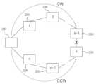
제2 실시형태는 광신호의 전달 방향의 관점에서 이중화 구성이 된다. 정상 작동 시에는 도 9의 시계방향으로 광신호를 전달하다가 이상 작동 시에는 반시계방향으로 광신호를 전달할 수 있는 것이다. 가령 도 10에 도시된 바와 같이 k번째 능동형 중간 배선반(200)에 연결된 주 케이블(300)에서 장애가 발생 시 k-1번 능동형 중간 배선반(200)까지는 시계방향(CW)으로 광신호를 전달하고, 그 이후의 k ~ n번째 능동형 중간 배선반(200)은 반시계방향(CCW)으로 광신호를 전달하여 전체 전화 회선을 정상 연결할 수 있다.2nd Embodiment becomes a dual structure from a viewpoint of the propagation direction of an optical signal. During normal operation, an optical signal is transmitted in a clockwise direction as shown in FIG. For example, as shown in FIG. 10, when a failure occurs in the
100 능동형 주 배선반110 교환기
120 제1 능동형 110 블록121, 213 아날로그 입출력 포트
122, 214 다중화 모듈123, 211 디지털 입출력 포트
124, 212 역다중화 모듈125, 215 광입출력 포트
126, 216 전광변환 모듈130 피뢰탄기반
200 능동형 중간 배선반210 제2 능동형 110 블록
300 주 케이블310 예비 케이블100 Active
120 1st active 110
122, 214
124, 212
126, 216 Electric
200 active
300
Claims (5)
Translated fromKorean상기 능동형 주 배선반(100)이 다수의 전화기로부터 신호를 받아 전화기를 상호 접속하는 교환기(110) 및 통화 신호를 상기 능동형 중간 배선반(200)에 전달하는 제1 능동형 110 블록(120)으로 구성되고,
상기 제1 능동형 110 블록(120)이 상기 교환기(110)와 아날로그 신호를 송수신하는 아날로그 입출력 포트(121);
상기 아날로그 입출력 포트(121)에 입력되는 아날로그 신호를 디지털 신호로 변환하면서 시분할 다중화하는 다중화 모듈(122);
상기 다중화 모듈(122)의 디지털 출력 신호를 상기 능동형 중간 배선반(200)에 출력하는 디지털 입출력 포트(123) 및
상기 디지털 입출력 포트(123)에서 입력되는 시분할된 디지털 신호를 아날로그 신호로 변환하면서 역다중화하는 역다중화 모듈(124)로 구성되며,
상기 능동형 중간 배선반(200)이 제2 능동형 110 블록(210)을 포함하여 구성되고,
상기 제2 능동형 110 블록(210)이 상기 능동형 주 배선반(100)에서 전송되는 디지털 신호를 수신하는 디지털 입출력 포트(211);
상기 디지털 입출력 포트(123)를 통해 전송되는 디지털 신호를 아날로그 신호로 변환하면서 역다중화하는 역다중화 모듈(212);
상기 전화기와 아날로그 신호를 송수신하는 아날로그 입출력 포트(213) 및
상기 아날로그 입출력 포트(121)에 입력되는 아날로그 신호를 디지털 신호로 변환하면서 시분할 다중화하는 다중화 모듈(214)로 구성되는 것을 특징으로 하는 능동적 회선 분배가 가능한 전화 배선반 시스템.
A telephone wiring board system composed of an active main wiring board (100) and an active intermediate wiring board (200),
The active main wiring board 100 is composed of an exchange 110 that receives signals from a plurality of phones and interconnects the phones and a first active 110 block 120 that transmits a call signal to the active intermediate wiring board 200,
an analog input/output port 121 through which the first active 110 block 120 transmits/receives an analog signal with the exchange 110;
a multiplexing module 122 for time division multiplexing while converting an analog signal input to the analog input/output port 121 into a digital signal;
A digital input/output port 123 outputting the digital output signal of the multiplexing module 122 to the active intermediate wiring board 200, and
It consists of a demultiplexing module 124 for demultiplexing while converting a time-division digital signal input from the digital input/output port 123 into an analog signal,
The active intermediate wiring board 200 is configured to include a second active 110 block 210,
a digital input/output port 211 through which the second active 110 block 210 receives a digital signal transmitted from the active main wiring board 100;
a demultiplexing module 212 for converting and demultiplexing the digital signal transmitted through the digital input/output port 123 into an analog signal;
An analog input/output port 213 for transmitting and receiving an analog signal with the phone, and
A telephone wiring board system capable of active line distribution, characterized in that it is composed of a multiplexing module (214) for time-division multiplexing while converting analog signals input to the analog input/output port (121) into digital signals.
상기 제1 능동형 110 블록(120)과 상기 제2 능동형 110 블록(210)의 디지털 입출력 포트(123)를 대체하여 광입출력 포트(125) 및 전광변환 모듈(126)이 구비되는 것을 특징으로 하는 능동적 회선 분배가 가능한 전화 배선반 시스템.
The method of claim 1,
Active, characterized in that an optical input/output port 125 and an electro-optical conversion module 126 are provided to replace the digital input/output ports 123 of the first active 110 block 120 and the second active 110 block 210 A telephone switchboard system capable of line distribution.
상기 능동형 주 배선반(100)의 제1 능동형 110 블록(120)의 광입출력 포트(125)와 능동형 중간 배선반(200)의 제2 능동형 110 블록(210)의 광입출력 포트(125)가 주 케이블(300)과 예비 케이블(310)로 P2P 연결되는 것을 특징으로 하는 능동적 회선 분배가 가능한 전화 배선반 시스템.
The method of claim 2,
The optical input/output port 125 of the first active 110 block 120 of the active main wiring board 100 and the optical input/output port 125 of the second active 110 block 210 of the active intermediate wiring board 200 are connected to the main cable ( 300) and a telephone wiring board system capable of active line distribution, characterized in that P2P connection with a spare cable (310).
상기 능동형 주 배선반(100)의 제1 능동형 110 블록(120)의 광입출력 포트(125)와 상기 능동형 중간 배선반(200)의 광입출력 포트(125)가 주 케이블(300)로 연결되고, 상기 능동형 중간 배선반(200)의 광입출력 포트(125)가 다음 능동형 중간 배선반(200)의 광입출력 포트(125)와 주 케이블(300)로 반복하여 연결되며, 마지막 능동형 중간 배선반(200)의 광입출력 포트(125)가 상기 능동형 주 배선반(100)의 제1 능동형 110 블록(120)의 광입출력 포트(125)와 주 케이블(300)로 연결되어, 상기 능동형 주 배선반(100)과 상기 능동형 중간 배선반(200)이 링 네트워크를 형성하는 것을 특징으로 하는 능동적 회선 분배가 가능한 전화 배선반 시스템.
The method of claim 2,
The optical input/output port 125 of the first active 110 block 120 of the active main wiring board 100 and the optical input/output port 125 of the active intermediate wiring board 200 are connected by a main cable 300, and the active type The optical input/output port 125 of the intermediate wiring board 200 is repeatedly connected to the optical input/output port 125 of the next active intermediate wiring board 200 with the main cable 300, and the optical input/output port of the last active intermediate wiring board 200 125 is connected to the optical input/output port 125 of the first active 110 block 120 of the active main wiring board 100 and the main cable 300, and the active main wiring board 100 and the active intermediate wiring board ( 200) is a telephone wiring board system capable of active line distribution, characterized in that it forms a ring network.
상기 능동형 주 배선반(100)과 능동형 중간 배선반(200)의 회선 연결 상황을 모니터링하여 통화 회선 연결 상황 파악 및 점퍼 코드 관리 대장 작성이 가능한 것을 특징으로 하는 능동적 회선 분배가 가능한 전화 배선반 시스템.
The method of claim 1,
A telephone wiring board system capable of active line distribution, characterized in that it is possible to check the call line connection situation and create a jumper code management ledger by monitoring the line connection status of the active main wiring board (100) and the active intermediate wiring board (200).
Priority Applications (1)
| Application Number | Priority Date | Filing Date | Title |
|---|---|---|---|
| KR1020230019232AKR102529754B1 (en) | 2023-02-14 | 2023-02-14 | Telephone distribution system capable of active circuit distribution |
Applications Claiming Priority (1)
| Application Number | Priority Date | Filing Date | Title |
|---|---|---|---|
| KR1020230019232AKR102529754B1 (en) | 2023-02-14 | 2023-02-14 | Telephone distribution system capable of active circuit distribution |
Publications (1)
| Publication Number | Publication Date |
|---|---|
| KR102529754B1true KR102529754B1 (en) | 2023-05-08 |
Family
ID=86381314
Family Applications (1)
| Application Number | Title | Priority Date | Filing Date |
|---|---|---|---|
| KR1020230019232AActiveKR102529754B1 (en) | 2023-02-14 | 2023-02-14 | Telephone distribution system capable of active circuit distribution |
Country Status (1)
| Country | Link |
|---|---|
| KR (1) | KR102529754B1 (en) |
Cited By (2)
| Publication number | Priority date | Publication date | Assignee | Title |
|---|---|---|---|---|
| KR102585840B1 (en)* | 2023-06-07 | 2023-10-06 | 주식회사 혜성테크윈 | Active patch panel and integrated data distribution system using the same |
| KR102664169B1 (en)* | 2024-02-23 | 2024-05-08 | 주식회사 혜성테크윈 | Active patch panel capable of setting inter-floor path of ethernet signals and integrated data distribution system using the same |
Citations (5)
| Publication number | Priority date | Publication date | Assignee | Title |
|---|---|---|---|---|
| KR20070110452A (en)* | 2000-04-18 | 2007-11-16 | 써코넷 리미티드 | Telephony system on a single telephone line |
| KR101905583B1 (en) | 2018-05-04 | 2018-10-10 | 주식회사 우리이엔시 | System for managing consolidated distribution frame and method therefor |
| KR101990607B1 (en)* | 2019-01-22 | 2019-09-30 | (주)인포스텍 | Automatic line numbering recognition method using active patch panels and integrated distribution network systems equipped with them |
| KR20200034326A (en)* | 2018-09-21 | 2020-03-31 | 주식회사 옵티코어 | Optical Fiber Distribution Apparatus Providing With Real time Subscriber Number Information And Network System Comprising The Same |
| KR20210102024A (en)* | 2020-02-10 | 2021-08-19 | 국제텔레시스(주) | Management system for automatic line numbering and real-time failure analysis of integrated distribution network systems |
- 2023
- 2023-02-14KRKR1020230019232Apatent/KR102529754B1/enactiveActive
Patent Citations (5)
| Publication number | Priority date | Publication date | Assignee | Title |
|---|---|---|---|---|
| KR20070110452A (en)* | 2000-04-18 | 2007-11-16 | 써코넷 리미티드 | Telephony system on a single telephone line |
| KR101905583B1 (en) | 2018-05-04 | 2018-10-10 | 주식회사 우리이엔시 | System for managing consolidated distribution frame and method therefor |
| KR20200034326A (en)* | 2018-09-21 | 2020-03-31 | 주식회사 옵티코어 | Optical Fiber Distribution Apparatus Providing With Real time Subscriber Number Information And Network System Comprising The Same |
| KR101990607B1 (en)* | 2019-01-22 | 2019-09-30 | (주)인포스텍 | Automatic line numbering recognition method using active patch panels and integrated distribution network systems equipped with them |
| KR20210102024A (en)* | 2020-02-10 | 2021-08-19 | 국제텔레시스(주) | Management system for automatic line numbering and real-time failure analysis of integrated distribution network systems |
Cited By (2)
| Publication number | Priority date | Publication date | Assignee | Title |
|---|---|---|---|---|
| KR102585840B1 (en)* | 2023-06-07 | 2023-10-06 | 주식회사 혜성테크윈 | Active patch panel and integrated data distribution system using the same |
| KR102664169B1 (en)* | 2024-02-23 | 2024-05-08 | 주식회사 혜성테크윈 | Active patch panel capable of setting inter-floor path of ethernet signals and integrated data distribution system using the same |
Similar Documents
| Publication | Publication Date | Title |
|---|---|---|
| KR102529754B1 (en) | Telephone distribution system capable of active circuit distribution | |
| US10454585B2 (en) | Data center network system and signal transmission system | |
| US5042062A (en) | Method and apparatus for providing real-time switching of high bandwidth transmission channels | |
| US5631902A (en) | Digital cross-connect system | |
| JP6367246B2 (en) | Communication network | |
| KR102585840B1 (en) | Active patch panel and integrated data distribution system using the same | |
| CN100589137C (en) | A Large-Scale Civil Defense Alarm Multilevel Control System | |
| US5311501A (en) | Routing system for linear add-drop multiplexer | |
| US20060159233A1 (en) | Re-arrangeable analog electrical cross connect | |
| WO2023273393A1 (en) | Optical cross-connect device and wavelength selective switch | |
| CN100336362C (en) | Method and apparatus for circumventing common control and switch arrays in digital switching systems | |
| JP6109402B2 (en) | Wavelength redundancy apparatus and wavelength redundancy method | |
| US8355497B2 (en) | Provision of telecommunication services | |
| CN1589586A (en) | Optical network nodes with add/drop functionality or cross-connect functionality | |
| KR102664169B1 (en) | Active patch panel capable of setting inter-floor path of ethernet signals and integrated data distribution system using the same | |
| US5434851A (en) | Digital telecommunications switching system | |
| US5555478A (en) | Fiber optic information transmission system | |
| US5027344A (en) | Integrated office controller (IOC) | |
| US6850517B1 (en) | System and method for high-capacity electronic switching | |
| RU105101U1 (en) | SHIP TELECOMMUNICATIONS NETWORK | |
| Schaffer | Switching in the broad-band ISDN | |
| US3649768A (en) | High capacity switching network and control arrangement | |
| JP6154686B2 (en) | Subscriber distribution apparatus and signal processing method thereof | |
| KR200287754Y1 (en) | Multy Hub | |
| AU666984B2 (en) | A method of connecting subscribers to a telephone exchange |
Legal Events
| Date | Code | Title | Description |
|---|---|---|---|
| PA0109 | Patent application | Patent event code:PA01091R01D Comment text:Patent Application Patent event date:20230214 | |
| PA0201 | Request for examination | ||
| PA0302 | Request for accelerated examination | Patent event date:20230216 Patent event code:PA03022R01D Comment text:Request for Accelerated Examination Patent event date:20230214 Patent event code:PA03021R01I Comment text:Patent Application | |
| E701 | Decision to grant or registration of patent right | ||
| PE0701 | Decision of registration | Patent event code:PE07011S01D Comment text:Decision to Grant Registration Patent event date:20230430 | |
| GRNT | Written decision to grant | ||
| PR0701 | Registration of establishment | Comment text:Registration of Establishment Patent event date:20230502 Patent event code:PR07011E01D | |
| PR1002 | Payment of registration fee | Payment date:20230502 End annual number:3 Start annual number:1 | |
| PG1601 | Publication of registration |