KR102529555B1 - System and method for Autonomous Emergency Braking - Google Patents
System and method for Autonomous Emergency BrakingDownload PDFInfo
- Publication number
- KR102529555B1 KR102529555B1KR1020160079356AKR20160079356AKR102529555B1KR 102529555 B1KR102529555 B1KR 102529555B1KR 1020160079356 AKR1020160079356 AKR 1020160079356AKR 20160079356 AKR20160079356 AKR 20160079356AKR 102529555 B1KR102529555 B1KR 102529555B1
- Authority
- KR
- South Korea
- Prior art keywords
- distance
- vehicle
- emergency braking
- height
- laser beams
- Prior art date
- Legal status (The legal status is an assumption and is not a legal conclusion. Google has not performed a legal analysis and makes no representation as to the accuracy of the status listed.)
- Active
Links
- 238000000034methodMethods0.000titleclaimsabstractdescription24
- 238000004364calculation methodMethods0.000claimsdescription17
- 238000003909pattern recognitionMethods0.000claimsdescription7
- 238000010586diagramMethods0.000description12
- 230000001678irradiating effectEffects0.000description4
- 230000007423decreaseEffects0.000description3
- 238000004519manufacturing processMethods0.000description2
- 238000007792additionMethods0.000description1
- 230000033228biological regulationEffects0.000description1
- 238000012986modificationMethods0.000description1
- 230000004048modificationEffects0.000description1
Images


Classifications
- B—PERFORMING OPERATIONS; TRANSPORTING
- B60—VEHICLES IN GENERAL
- B60W—CONJOINT CONTROL OF VEHICLE SUB-UNITS OF DIFFERENT TYPE OR DIFFERENT FUNCTION; CONTROL SYSTEMS SPECIALLY ADAPTED FOR HYBRID VEHICLES; ROAD VEHICLE DRIVE CONTROL SYSTEMS FOR PURPOSES NOT RELATED TO THE CONTROL OF A PARTICULAR SUB-UNIT
- B60W30/00—Purposes of road vehicle drive control systems not related to the control of a particular sub-unit, e.g. of systems using conjoint control of vehicle sub-units
- B60W30/08—Active safety systems predicting or avoiding probable or impending collision or attempting to minimise its consequences
- B60W30/09—Taking automatic action to avoid collision, e.g. braking and steering
- B—PERFORMING OPERATIONS; TRANSPORTING
- B60—VEHICLES IN GENERAL
- B60R—VEHICLES, VEHICLE FITTINGS, OR VEHICLE PARTS, NOT OTHERWISE PROVIDED FOR
- B60R21/00—Arrangements or fittings on vehicles for protecting or preventing injuries to occupants or pedestrians in case of accidents or other traffic risks
- B60R21/01—Electrical circuits for triggering passive safety arrangements, e.g. airbags, safety belt tighteners, in case of vehicle accidents or impending vehicle accidents
- B60R21/013—Electrical circuits for triggering passive safety arrangements, e.g. airbags, safety belt tighteners, in case of vehicle accidents or impending vehicle accidents including means for detecting collisions, impending collisions or roll-over
- B60R21/0134—Electrical circuits for triggering passive safety arrangements, e.g. airbags, safety belt tighteners, in case of vehicle accidents or impending vehicle accidents including means for detecting collisions, impending collisions or roll-over responsive to imminent contact with an obstacle, e.g. using radar systems
- B—PERFORMING OPERATIONS; TRANSPORTING
- B60—VEHICLES IN GENERAL
- B60W—CONJOINT CONTROL OF VEHICLE SUB-UNITS OF DIFFERENT TYPE OR DIFFERENT FUNCTION; CONTROL SYSTEMS SPECIALLY ADAPTED FOR HYBRID VEHICLES; ROAD VEHICLE DRIVE CONTROL SYSTEMS FOR PURPOSES NOT RELATED TO THE CONTROL OF A PARTICULAR SUB-UNIT
- B60W40/00—Estimation or calculation of non-directly measurable driving parameters for road vehicle drive control systems not related to the control of a particular sub unit, e.g. by using mathematical models
- B60W40/02—Estimation or calculation of non-directly measurable driving parameters for road vehicle drive control systems not related to the control of a particular sub unit, e.g. by using mathematical models related to ambient conditions
- B—PERFORMING OPERATIONS; TRANSPORTING
- B60—VEHICLES IN GENERAL
- B60W—CONJOINT CONTROL OF VEHICLE SUB-UNITS OF DIFFERENT TYPE OR DIFFERENT FUNCTION; CONTROL SYSTEMS SPECIALLY ADAPTED FOR HYBRID VEHICLES; ROAD VEHICLE DRIVE CONTROL SYSTEMS FOR PURPOSES NOT RELATED TO THE CONTROL OF A PARTICULAR SUB-UNIT
- B60W50/00—Details of control systems for road vehicle drive control not related to the control of a particular sub-unit, e.g. process diagnostic or vehicle driver interfaces
- B60W50/08—Interaction between the driver and the control system
- B60W50/14—Means for informing the driver, warning the driver or prompting a driver intervention
- G—PHYSICS
- G01—MEASURING; TESTING
- G01S—RADIO DIRECTION-FINDING; RADIO NAVIGATION; DETERMINING DISTANCE OR VELOCITY BY USE OF RADIO WAVES; LOCATING OR PRESENCE-DETECTING BY USE OF THE REFLECTION OR RERADIATION OF RADIO WAVES; ANALOGOUS ARRANGEMENTS USING OTHER WAVES
- G01S13/00—Systems using the reflection or reradiation of radio waves, e.g. radar systems; Analogous systems using reflection or reradiation of waves whose nature or wavelength is irrelevant or unspecified
- G01S13/88—Radar or analogous systems specially adapted for specific applications
- G01S13/93—Radar or analogous systems specially adapted for specific applications for anti-collision purposes
- G01S13/931—Radar or analogous systems specially adapted for specific applications for anti-collision purposes of land vehicles
- G—PHYSICS
- G01—MEASURING; TESTING
- G01S—RADIO DIRECTION-FINDING; RADIO NAVIGATION; DETERMINING DISTANCE OR VELOCITY BY USE OF RADIO WAVES; LOCATING OR PRESENCE-DETECTING BY USE OF THE REFLECTION OR RERADIATION OF RADIO WAVES; ANALOGOUS ARRANGEMENTS USING OTHER WAVES
- G01S17/00—Systems using the reflection or reradiation of electromagnetic waves other than radio waves, e.g. lidar systems
- G01S17/88—Lidar systems specially adapted for specific applications
- G01S17/93—Lidar systems specially adapted for specific applications for anti-collision purposes
- G01S17/931—Lidar systems specially adapted for specific applications for anti-collision purposes of land vehicles
- B—PERFORMING OPERATIONS; TRANSPORTING
- B60—VEHICLES IN GENERAL
- B60W—CONJOINT CONTROL OF VEHICLE SUB-UNITS OF DIFFERENT TYPE OR DIFFERENT FUNCTION; CONTROL SYSTEMS SPECIALLY ADAPTED FOR HYBRID VEHICLES; ROAD VEHICLE DRIVE CONTROL SYSTEMS FOR PURPOSES NOT RELATED TO THE CONTROL OF A PARTICULAR SUB-UNIT
- B60W50/00—Details of control systems for road vehicle drive control not related to the control of a particular sub-unit, e.g. process diagnostic or vehicle driver interfaces
- B60W50/08—Interaction between the driver and the control system
- B60W50/14—Means for informing the driver, warning the driver or prompting a driver intervention
- B60W2050/146—Display means
- B—PERFORMING OPERATIONS; TRANSPORTING
- B60—VEHICLES IN GENERAL
- B60W—CONJOINT CONTROL OF VEHICLE SUB-UNITS OF DIFFERENT TYPE OR DIFFERENT FUNCTION; CONTROL SYSTEMS SPECIALLY ADAPTED FOR HYBRID VEHICLES; ROAD VEHICLE DRIVE CONTROL SYSTEMS FOR PURPOSES NOT RELATED TO THE CONTROL OF A PARTICULAR SUB-UNIT
- B60W2420/00—Indexing codes relating to the type of sensors based on the principle of their operation
- B60W2420/40—Photo, light or radio wave sensitive means, e.g. infrared sensors
- B60W2420/408—Radar; Laser, e.g. lidar
- B60W2420/52—
- B60W2420/62—
Landscapes
- Engineering & Computer Science (AREA)
- Radar, Positioning & Navigation (AREA)
- Remote Sensing (AREA)
- Automation & Control Theory (AREA)
- Mechanical Engineering (AREA)
- Physics & Mathematics (AREA)
- Transportation (AREA)
- Electromagnetism (AREA)
- Computer Networks & Wireless Communication (AREA)
- General Physics & Mathematics (AREA)
- Mathematical Physics (AREA)
- Human Computer Interaction (AREA)
- Traffic Control Systems (AREA)
Abstract
Translated fromKoreanDescription
Translated fromKorean본 발명은 정지 물체와 이동 물체를 구분하고, 상기 정지 물체와 이동 물체가 위치한 높이를 판단하여 긴급 제동이 이루어지도록 한 자율 긴급 제동 시스템 및 이의 구동 방법에 관한 것이다.The present invention relates to an autonomous emergency braking system and a method of driving the same that distinguishes between a stationary object and a moving object and determines the height at which the stationary object and the moving object are located to perform emergency braking.
최근 차량 전방에 물체가 감지될 경우, 경보 및 자동 제동 기능을 수행함으로써 충돌에 의한 피해를 최소화 할 수 있는 시스템인 자율 긴급 제동 시스템(AEB: Autonomous Emergency Braking )이 개발되고 있다.Recently, an autonomous emergency braking system (AEB), which is a system capable of minimizing damage caused by a collision by performing an alarm and an automatic braking function when an object is detected in front of the vehicle, has been developed.
자율긴급 제동 시스템은 차량에 탑재된 레이더를 통해 전방에 주행중인 차량(또는 물체)과의 거리를 측정하며, 자차와 전방 차량과의 거리가 일정 거리 보다 가까운 경우에 충돌(또는 추돌) 위험을 인식한다. 충돌 위험이 인식되면, 자동으로 제동이 이루어지도록 함으로서 차량 속도를 감속시킨다. 또한, 자율 긴급 제동 시스템은 충돌 위험을 감지하면, 운전자에게 경고음으로 충돌 위험을 알리고, 운전자의 페달 조작에 신속히 반응할 수 있도록 제동 장치를 대기 모드로 동작시킨다. 나아가, 충돌의 위험이 있는 경우 운전자의 의지와 상관 없이 브레이크를 자동으로 작동시켜 차량을 감속시킨다.The autonomous emergency braking system measures the distance to the vehicle (or object) driving in front through the radar mounted on the vehicle, and recognizes the risk of collision (or collision) when the distance between the own vehicle and the vehicle in front is closer than a certain distance. do. When a risk of collision is recognized, the vehicle speed is reduced by automatically applying braking. In addition, when the autonomous emergency braking system detects a risk of collision, it notifies the driver of the risk of collision with a warning sound and operates the brake system in a standby mode so as to quickly respond to the driver's pedal operation. Furthermore, when there is a risk of collision, the brake is automatically applied to decelerate the vehicle regardless of the driver's will.
이러한 자율 긴급 제동의 성능을 높이기 위해서는 차량 전방의 물체가 보행자인지, 차량인지, 또는 이외의 다른 물체인지를 빠르고 정확하게 판별하여야 한다. 그러나 종래 기술의 자율 긴급 제동 시스템은 물체에 대한 높이 측정 기능이 없고, 물체의 종류 판단 기능이 없기 때문에 충돌 위험이 없는 정지한 물체에 대해서 자율 긴급 제동이 이루어지는 문제점이 있다. 특히, 도로표지판, 도로 바닥에 표시된 도로 정보를 충돌 가능성이 있는 물체로 오인하여 불필요한 긴급 제동이 이루어지게 하는 문제점이 있다.In order to improve the performance of autonomous emergency braking, it is necessary to quickly and accurately determine whether an object in front of the vehicle is a pedestrian, a vehicle, or another object. However, the autonomous emergency braking system of the prior art has a problem in that autonomous emergency braking is performed for a stationary object without a risk of collision because there is no function for measuring the height of an object and no function for determining the type of an object. In particular, there is a problem in that unnecessary emergency braking is performed by mistaking road information displayed on a road sign or on the road floor as an object with a possibility of collision.
본 발명은 앞에서 설명한 문제점을 해결하기 위한 것으로, 전방의 물체간의 거리, 물체의 높이 및 물체가 위치한 높이를 측정하여 물체간의 충돌 가능성을 판단하고, 판단 결과에 기초하여 비상 상황에서 긴급 제동을 실행하는 긴급 제동 시스템 및 이의 구동 방법을 제공하는 것을 기술적 과제로 한다.The present invention is to solve the problems described above, to determine the possibility of collision between objects by measuring the distance between objects in front, the height of the object, and the height at which the object is located, and to execute emergency braking in an emergency situation based on the determination result. It is a technical task to provide an emergency braking system and a driving method thereof.
위에서 언급된 본 발명의 기술적 과제 외에도, 본 발명의 다른 특징 및 이점들이 이하에서 기술되거나, 그러한 기술 및 설명으로부터 본 발명이 속하는 기술분야에서 통상의 지식을 가진 자에게 명확하게 이해될 수 있을 것이다.In addition to the technical problems of the present invention mentioned above, other features and advantages of the present invention will be described below, or will be clearly understood by those skilled in the art from such description and description.
앞에서 설명한 목적을 달성하기 위한 본 발명의 실시 예에 따른 자율 긴급 제동 시스템은, 전방 물체를 감지하는 레이더와, 제1 레이저 빔과 제2 레이저 빔을 출력하는 라인 레이저와, 차량 전방을 촬영하여 전방 영상을 획득하는 영상 획득부와, 상기 제1 및 제2 레이저 빔을 포함하는 전방 영상을 표시하는 디스플레이부와, 물체가 감지된 경우, 상기 전방 영상에서 상기 제1 및 제2 레이저 빔의 패턴을 인식하고, 상기 제1 및 제2 레이저 빔의 패턴 중 수직 성분을 검출하는 패턴 인식부와, 상기 제1 및 제2 레이저 빔의 패턴에 기초하여 차량과 물체간의 거리 및 물체의 높이를 산출하는 산출부 및 상기 차량과 물체간의 거리 및 물체의 높이 산출 결과를 디스플레이부에 전송하고, 상기 차량과 상기 물체의 충돌 여부를 판단하고, 판단 결과에 따라 긴급 제동이 이루어지도록 차량을 제어하는 제어부를 포함한다.An autonomous emergency braking system according to an embodiment of the present invention for achieving the above object is a radar for detecting an object in front, a line laser for outputting a first laser beam and a second laser beam, and a front of the vehicle by photographing the front of the vehicle. An image acquisition unit acquiring an image, a display unit displaying a front image including the first and second laser beams, and a pattern of the first and second laser beams in the front image when an object is detected. a pattern recognizing unit configured to recognize and detect a vertical component among patterns of the first and second laser beams, and calculate a distance between the vehicle and the object and a height of the object based on the patterns of the first and second laser beams and a control unit that transmits results of calculating the distance between the vehicle and the object and the height of the object to the display unit, determines whether the vehicle collides with the object, and controls the vehicle to perform emergency braking according to the determination result. .
본 발명의 실시 예에 따른 자율 긴급 제동 시스템의 상기 산출부는, 상기 제1 및 제2 레이저 빔의 패턴의 하단부터 수직 성분의 시작지점까지의 수직거리를 산출하여 차량과 상기 물체간의 거리를 산출한다.The calculation unit of the autonomous emergency braking system according to an embodiment of the present invention calculates the distance between the vehicle and the object by calculating the vertical distance from the lower end of the pattern of the first and second laser beams to the starting point of the vertical component. .
본 발명의 실시 예에 따른 자율 긴급 제동 시스템의 상기 산출부는, 상기 제1 레이저 빔과 상기 제2 레이저 빔 사이의 너비를 산출하여 차량과 상기 물체간의 거리를 보정한다.The calculation unit of the autonomous emergency braking system according to an embodiment of the present invention calculates a width between the first laser beam and the second laser beam and corrects the distance between the vehicle and the object.
본 발명의 실시 예에 따른 자율 긴급 제동 시스템의 상기 산출부는, 상기 제1 및 제2 레이저 빔의 패턴의 수직 성분의 길이를 산출하여 상기 물체의 높이를 산출한다.The calculator of the autonomous emergency braking system according to an embodiment of the present invention calculates the height of the object by calculating lengths of vertical components of patterns of the first and second laser beams.
본 발명의 실시 예에 따른 자율 긴급 제동 시스템의 상기 제어부는, 상기 차량과 물체간의 거리 및 물체의 높이 산출 결과를 상기 디스플레이부로 전송하고, 상기 디스플레이부는 상기 차량과 물체간의 거리 정보 및 물체의 높이 산출 정보를 표시한다.The control unit of the autonomous emergency braking system according to an embodiment of the present invention transmits the calculation result of the distance between the vehicle and the object and the height of the object to the display unit, and the display unit calculates the distance information between the vehicle and the object and the height of the object. display information
본 발명의 실시 예에 따른 자율 긴급 제동 시스템의 상기 제어부는, 상기 제1 및 제2 레이저 빔의 패턴에 기초하여 검출된 물체와 차량간의 제1 거리 및 상기 레이더에서 검출된 물체와 차량간의 제2 거리를 비교하고, 상기 제1 거리와 상기 제2 거리가 동일한 경우, 상기 레이더에서 검출한 물체에 높이 정보를 부여한다.The controller of the autonomous emergency braking system according to an embodiment of the present invention may include a first distance between an object and the vehicle detected based on the patterns of the first and second laser beams and a second distance between the object and the vehicle detected by the radar. The distances are compared, and when the first distance and the second distance are equal, height information is given to the object detected by the radar.
본 발명의 실시 예에 따른 자율 긴급 제동 시스템의 상기 제어부는, 상기 물체의 높이가 기준 값 이상인 경우에 긴급 제동을 수행하고, 상기 물체의 높이가 기준 값 미만인 경우에 긴급 제동을 수행하지 않는다.The controller of the autonomous emergency braking system according to an embodiment of the present invention performs emergency braking when the height of the object is greater than or equal to a reference value, and does not perform emergency braking when the height of the object is less than the reference value.
본 발명의 실시 예에 따른 자율 긴급 제동 시스템의 상기 제어부는, 상기 레이더에서 검출한 물체의 거리에 해당하는 상기 제1 및 제2 레이저 빔의 패턴에서 수직 성분이 검출되지 않으면 긴급 제동을 수행하지 않는다.The controller of the autonomous emergency braking system according to an embodiment of the present invention does not perform emergency braking if vertical components are not detected in the patterns of the first and second laser beams corresponding to the distance of the object detected by the radar. .
본 발명의 실시 예에 따른 자율 긴급 제동 시스템의 구동 방법은, 레이더를 이용한 물체의 거리 정보 및 상기 제1 및 제2 레이저 빔의 패턴을 이용한 물체의 높이 정보에 기초하여 긴급 제동을 수행하되, 상기 물체의 높이에 기초하여 충돌 위험이 있는 물체를 구분하고, 충돌 위험이 있는 물체에 대해서 선별적으로 긴급 제동을 수행한다.A driving method of an autonomous emergency braking system according to an embodiment of the present invention performs emergency braking based on distance information of an object using radar and height information of the object using patterns of the first and second laser beams, Objects with a risk of collision are classified based on the height of the object, and emergency braking is selectively performed on the object with a risk of collision.
본 발명의 실시 예에 따른 자율 긴급 제동 시스템의 구동 방법은, 상기 제1 및 상기 제2 레이저 빔의 패턴에서 수직 성분을 검출하고, 상기 수직 성분의 길이를 산출하여 상기 물체의 높이를 산출한다.In the driving method of the autonomous emergency braking system according to an embodiment of the present invention, the height of the object is calculated by detecting vertical components from patterns of the first and second laser beams and calculating lengths of the vertical components.
본 발명의 실시 예에 따른 자율 긴급 제동 시스템의 구동 방법은, 상기 제1 및 상기 제2 레이저 빔의 패턴의 하단부터 수직성분 시작지점까지의 수직 거리를 산출하여 차량과 상기 물체와의 거리를 산출한다.In the driving method of the autonomous emergency braking system according to an embodiment of the present invention, the distance between the vehicle and the object is calculated by calculating the vertical distance from the lower end of the pattern of the first and second laser beams to the starting point of the vertical component. do.
본 발명의 실시 예에 따른 자율 긴급 제동 시스템의 구동 방법은, 상기 제1 레이저 빔의 패턴 및 상기 제2 레이저 빔의 패턴 사이의 너비를 산출하여 차량과 상기 물체간의 거리를 보정한다.In the driving method of the autonomous emergency braking system according to an embodiment of the present invention, the distance between the vehicle and the object is corrected by calculating the width between the pattern of the first laser beam and the pattern of the second laser beam.
본 발명의 실시 예에 따른 자율 긴급 제동 시스템의 구동 방법은, 상기 제1 및 제2 레이저 빔의 패턴에서 산출한 물체의 거리와 레이더에서 검출된 물체의 거리를 비교하고, 상기 물체의 거리가 동일한 경우, 레이더에서 검출된 물체에 높이 정보를 부여한다.In the driving method of the autonomous emergency braking system according to an embodiment of the present invention, the distance of the object calculated from the patterns of the first and second laser beams and the distance of the object detected by the radar are compared, and the distance of the object is the same. In this case, height information is given to the object detected by the radar.
본 발명의 실시 예에 따른 자율 긴급 제동 시스템의 구동 방법은, 상기 물체의 높이가 기준 값 이상이면 긴급 제동을 수행한다.In the driving method of the autonomous emergency braking system according to an embodiment of the present invention, emergency braking is performed when the height of the object is greater than or equal to a reference value.
본 발명의 실시 예에 따른 자율 긴급 제동 시스템의 구동 방법은, 상기 물체의 높이가 기준 값 미만이면 긴급 제동을 수행하지 않는다.In the driving method of the autonomous emergency braking system according to an embodiment of the present invention, emergency braking is not performed when the height of the object is less than a reference value.
본 발명의 실시 예에 따른 자율 긴급 제동 시스템 및 이의 구동 방법은 충돌 위험이 있는 이동 물체 및 정지 물체를 검출하여 자율 긴급 제동 시스템의 성능을 향상시킬 수 있다.The autonomous emergency braking system and its driving method according to an embodiment of the present invention can improve the performance of the autonomous emergency braking system by detecting a moving object and a stationary object with a risk of collision.
본 발명의 실시 예에 따른 자율 긴급 제동 시스템 및 이의 구동 방법은 충돌 위험이 없는 정지 물체를 구분하여 불필요한 긴급 제동을 방지할 수 있다.An autonomous emergency braking system and a method for driving the same according to an embodiment of the present invention can prevent unnecessary emergency braking by classifying a stationary object with no risk of collision.
본 발명의 실시 예에 따른 자율 긴급 제동 시스템 및 이의 구동 방법은 저가의 라인레이저의 적용을 통해 자율 긴급 제동 시스템의 성능을 향상시킴과 아울러, 자율 긴급 제동 시스템의 제조 비용을 줄일 수 있다.The autonomous emergency braking system and its driving method according to an embodiment of the present invention can improve the performance of the autonomous emergency braking system and reduce the manufacturing cost of the autonomous emergency braking system through the application of a low-cost line laser.
이 밖에도, 본 발명의 실시 예들을 통해 본 발명의 또 다른 특징 및 이점들이 새롭게 파악될 수도 있을 것이다.In addition, other features and advantages of the present invention may be newly identified through the embodiments of the present invention.
도 1은 본 발명의 실시 예에 따른 자율 긴급 제동 시스템을 나타내는 도면이다.
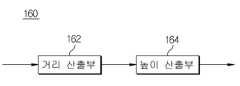
도 2는 도 1에 도시된 산출부를 나타내는 도면이다.
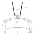
도 3은 라인레이저에서 조사되는 레이저 빔의 조사방향을 나타내는 도면이다.
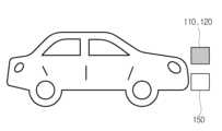
도 4는 차량에 배치된 라인레이저와 영상 획득부 및 레이더를 나타내는 도면이다.
도 5는 물체의 유/무에 따른 레이저 빔의 패턴을 나타내는 도면이다.
도 6은 차량 전방에 물체가 있을 때 레이저 빔의 패턴을 나타내는 도면이다.
도 7은 본 발명의 실시 예에 따른 차량의 자율 긴급 제동 시스템의 구동 방법을 나타내는 도면이다.1 is a diagram illustrating an autonomous emergency braking system according to an embodiment of the present invention.
FIG. 2 is a diagram illustrating a calculation unit shown in FIG. 1 .
3 is a view showing the irradiation direction of a laser beam irradiated from a line laser.
4 is a diagram illustrating a line laser, an image acquisition unit, and a radar disposed in a vehicle.
5 is a diagram showing a pattern of a laser beam according to presence/absence of an object.
6 is a diagram illustrating a pattern of a laser beam when there is an object in front of the vehicle.
7 is a diagram illustrating a driving method of an autonomous emergency braking system for a vehicle according to an embodiment of the present invention.
이하, 첨부한 도면을 참고로 하여 본 발명의 실시 예에 대하여 본 발명이 속하는 기술 분야에서 통상의 지식을 가진 자가 용이하게 실시할 수 있도록 상세히 설명한다. 본 발명은 여러 가지 상이한 형태로 구현될 수 있으며 여기에서 설명하는 실시 예에 한정되지 않는다.Hereinafter, with reference to the accompanying drawings, embodiments of the present invention will be described in detail so that those skilled in the art can easily carry out the present invention. The present invention may be embodied in many different forms and is not limited to the embodiments described herein.
본 발명을 명확하게 설명하기 위해서 설명과 관계없는 부분은 생략하였으며, 명세서 전체를 통하여 동일 또는 유사한 구성요소에 대해서는 동일한 참조 부호를 붙이도록 한다.In order to clearly describe the present invention, parts irrelevant to the description are omitted, and the same reference numerals are assigned to the same or similar components throughout the specification.
명세서 전체에서, 어떤 부분이 다른 부분과 "연결"되어 있다고 할 때, 이는 "직접적으로 연결"되어 있는 경우뿐 아니라, 그 중간에 다른 소자를 사이에 두고 "전기적으로 연결"되어 있는 경우도 포함한다. 또한 어떤 부분이 어떤 구성요소를 "포함"한다고 할 때, 이는 특별히 반대되는 기재가 없는 한 다른 구성요소를 제외하는 것이 아니라 다른 구성요소를 더 포함할 수 있는 것을 의미한다.Throughout the specification, when a part is said to be "connected" to another part, this includes not only the case where it is "directly connected" but also the case where it is "electrically connected" with another element interposed therebetween. . In addition, when a certain component is said to "include", this means that it may further include other components without excluding other components unless otherwise stated.
어느 부분이 다른 부분의 "위에" 있다고 언급하는 경우, 이는 바로 다른 부분의 위에 있을 수 있거나 그 사이에 다른 부분이 수반될 수 있다. 대조적으로 어느 부분이 다른 부분의 "바로 위에" 있다고 언급하는 경우, 그 사이에 다른 부분이 수반되지 않는다.When a part is referred to as being “on” another part, it may be directly on top of the other part or may have other parts in between. In contrast, when a part is said to be “directly on” another part, there are no other parts in between.
제1, 제2 및 제3 등의 용어들은 다양한 부분, 성분, 영역, 층 및/또는 섹션들을 설명하기 위해 사용되나 이들에 한정되지 않는다. 이들 용어들은 어느 부분, 성분, 영역, 층 또는 섹션을 다른 부분, 성분, 영역, 층 또는 섹션과 구별하기 위해서만 사용된다. 따라서, 이하에서 서술하는 제1 부분, 성분, 영역, 층 또는 섹션은 본 발명의 범위를 벗어나지 않는 범위 내에서 제2 부분, 성분, 영역, 층 또는 섹션으로 언급될 수 있다.Terms such as first, second and third are used to describe, but are not limited to, various parts, components, regions, layers and/or sections. These terms are only used to distinguish one part, component, region, layer or section from another part, component, region, layer or section. Accordingly, a first part, component, region, layer or section described below may be referred to as a second part, component, region, layer or section without departing from the scope of the present invention.
여기서 사용되는 전문 용어는 단지 특정 실시 예를 언급하기 위한 것이며, 본 발명을 한정하는 것을 의도하지 않는다. 여기서 사용되는 단수 형태들은 문구들이 이와 명백히 반대의 의미를 나타내지 않는 한 복수 형태들도 포함한다. 명세서에서 사용되는 "포함하는"의 의미는 특정 특성, 영역, 정수, 단계, 동작, 요소 및/또는 성분을 구체화하며, 다른 특성, 영역, 정수, 단계, 동작, 요소 및/또는 성분의 존재나 부가를 제외시키는 것은 아니다.The terminology used herein is only for referring to specific embodiments and is not intended to limit the present invention. As used herein, the singular forms also include the plural forms unless the phrases clearly indicate the opposite. The meaning of "comprising" as used herein specifies particular characteristics, regions, integers, steps, operations, elements and/or components, and the presence or absence of other characteristics, regions, integers, steps, operations, elements and/or components. Additions are not excluded.
"아래", "위" 등의 상대적인 공간을 나타내는 용어는 도면에서 도시된 한 부분의 다른 부분에 대한 관계를 보다 쉽게 설명하기 위해 사용될 수 있다. 이러한 용어들은 도면에서 의도한 의미와 함께 사용 중인 장치의 다른 의미나 동작을 포함하도록 의도된다. 예를 들면, 도면 중의 장치를 뒤집으면, 다른 부분들의 "아래"에 있는 것으로 설명된 어느 부분들은 다른 부분들의 "위"에 있는 것으로 설명된다. 따라서 "아래"라는 예시적인 용어는 위와 아래 방향을 전부 포함한다. 장치는 90˚ 회전 또는 다른 각도로 회전할 수 있고, 상대적인 공간을 나타내는 용어도 이에 따라서 해석된다.Terms indicating relative space, such as “below” and “above,” may be used to more easily describe the relationship of one part to another shown in the drawings. These terms are intended to include other meanings or operations of the device in use with the meaning intended in the drawings. For example, if the device in the figures is turned over, certain parts described as being “below” other parts will be described as being “above” the other parts. Thus, the exemplary term "below" includes both directions above and below. The device may rotate 90 degrees or other angles, and terms denoting relative space are interpreted accordingly.
다르게 정의하지는 않았지만, 여기에 사용되는 기술용어 및 과학용어를 포함하는 모든 용어들은 본 발명이 속하는 기술분야에서 통상의 지식을 가진 자가 일반적으로 이해하는 의미와 동일한 의미를 가진다. 보통 사용되는 사전에 정의된 용어들은 관련 기술문헌과 현재 개시된 내용에 부합하는 의미를 가지는 것으로 추가 해석되고, 정의되지 않는 한 이상적이거나 매우 공식적인 의미로 해석되지 않는다.Although not defined differently, all terms including technical terms and scientific terms used herein have the same meaning as commonly understood by those of ordinary skill in the art to which the present invention belongs. Terms defined in commonly used dictionaries are additionally interpreted as having meanings consistent with related technical literature and currently disclosed content, and are not interpreted in ideal or very formal meanings unless defined.
이하, 첨부한 도면을 참조하여 본 발명의 실시 예에 대하여 본 발명이 속하는 기술분야에서 통상의 지식을 가진 자가 용이하게 실시할 수 있도록 상세히 설명한다. 그러나 본 발명은 여러 가지 상이한 형태로 구현될 수 있으며 여기에서 설명하는 실시 예에 한정되지 않는다.Hereinafter, with reference to the accompanying drawings, embodiments of the present invention will be described in detail so that those skilled in the art can easily carry out the present invention. However, the present invention may be implemented in many different forms and is not limited to the embodiments described herein.
도 1은 본 발명의 실시 예에 따른 자율 긴급 제동 시스템을 나타내는 도면이고, 도 2는 도 1에 도시된 산출부를 나타내는 도면이다.FIG. 1 is a diagram showing an autonomous emergency braking system according to an embodiment of the present invention, and FIG. 2 is a diagram showing a calculation unit shown in FIG. 1 .
도 1 및 도 2를 참조하면, 본 발명의 실시 예에 따른 자율 긴급 제동 시스템(100)은 라인레이저(110), 영상 획득부(120), 디스플레이부(130) 패턴 인식부(140), 레이더(150), 산출부(160) 및 제어부(170)를 포함한다. 여기서, 산출부(150)는 거리 산출부(162) 및 높이 산출부(164)를 포함한다.1 and 2, the autonomous
라인레이저(110)는 차량 전방의 좌측 및 우측에 부착되어 도로의 바닥을 향해 제1 레이저 빔과 제2 레이저 빔을 출력한다. 여기서, 라인레이저 빔이 도로 바닥을 향하도록 조사됨으로 도로의 상측에 위치한 교통 표지판에는 레이저 빔이 조사되지 않는다.The
영상 획득부(120)는 카메라를 통해 차량의 전방을 촬영한 영상 데이터를 획득한다. 이 때, 영상 획득부(120)는 차량의 전방뿐만 아니라 차량의 후방 및 측면을 촬영한 영상 데이터도 획득할 수 있다.The
디스플레이부(130)는 영상 획득부(120)에서 획득한 상기 전방 영상을 화면에 표시한다. 이 때, 상기 제1 및 제2 레이저 빔을 포함하여 화면에 표시한다.The
레이더(150)는 전자기파를 발사시켜 물체에서 반사되는 전자기파를 수신한다. 이를 통해, 물체의 위치, 차량과 물체와의 거리, 물체의 방향, 물체의 움직임 속도를 감지한다.The
도 3은 라인레이저에서 조사되는 레이저 빔의 조사방향을 나타내는 도면이다.3 is a view showing the irradiation direction of a laser beam irradiated from a line laser.
도 3에 도시된 바와 같이, 영상 획득부(120)는 차량 전방에 부착되고, 제1 및 제2 레이저 빔(112)이 각각 차량의 바깥쪽을 향하도록 영상 획득부(120)의 양쪽에 라인레이저(110)가 부착된다.As shown in FIG. 3, the
도 4는 차량에 배치된 라인레이저와 영상 획득부 및 레이더를 나타내는 도면이다.4 is a diagram illustrating a line laser, an image acquisition unit, and a radar disposed in a vehicle.
도 4에 도시된 바와 같이, 영상 획득부(120)는 차량에 배치되어 차량의 전방을 촬영하여 영상 데이터를 생성한다. 여기서, 차량의 좌측 및 우측에서 제1 레이저 빔과 제2 레이저 빔이 조사됨으로, 영상 데이터에는 제 1 레이저 빔 및 제2 레이저 빔이 포함된다. 따라서, 디스플레이부(130)에는 제1 레이저 빔 및 제2 레이저 빔이 표시된 전방 영상이 표시된다. 상기 제1 및 제2 레이저 빔을 포함한 전방 영상은 패턴 인식부(140)로 전달된다. 한편, 레이더(150)는 차량 전방에 부착되어 차량 전방의 물체와의 거리, 위치, 방향, 속도 등을 감지한다.As shown in FIG. 4 , the
패턴 인식부(140)는 디스플레이부(130)에 표시된 영상에서 제1 및 제2 레이저 빔의 패턴(114)을 인식하고, 제1 및 제2 레이저 빔의 패턴(114)에서 수직 성분(114a)을 검출한다. 제1 및 제2 레이저 빔의 패턴(114)은 라인레이저(110)가 온(ON)이 되었을 때 제1 및 제2 레이저 빔이 조사되고, 디스플레이부(130)에 표시된 영상에서 제1 및 제2 레이저 빔의 패턴(114)을 분석하여 수직 성분(114a)을 검출할 수 있다.The
도 5는 물체의 유/무에 따른 레이저 빔의 패턴을 나타내는 도면이고, 도 6은 차량 전방에 물체가 있을 때 레이저 빔의 패턴을 나타내는 도면이다.5 is a diagram showing a pattern of a laser beam according to presence/absence of an object, and FIG. 6 is a diagram showing a pattern of a laser beam when an object is present in front of the vehicle.
도 5 및 도 6을 참조하면, 전방의 물체가 없는 경우 제1 및 제2 레이저 빔의 패턴(114)은 각각 차량의 바깥쪽으로 뻗은 직선 형태로 나타난다. 그러나, 차량의 전방에 물체가 있는 경우 제1 및 제2 레이저 빔이 물체에 중첩됨으로, 제1 및 제2 레이저 빔의 패턴(114)은 물체의 높이에 비례하여 꺾인 형태로 나타난다. 따라서, 패턴 인식부(140)는 상기 제1 및 제2 레이저 빔의 패턴(114)이 각각 차량의 바깥쪽으로 뻗은 직선 형태로 나타나면 차량의 전방에 물체가 없다고 판단한다.Referring to FIGS. 5 and 6 , when there is no object in front, the
반대로, 패턴 인식부(140)는 상기 제1 및 제2 레이저 빔의 패턴(114)에서 꺾인 형태가 나타나 수직 성분이 검출되면 차량의 전방에 물체가 있다고 판단한다. 여기서, 물체의 크기 및 위치에 따라서 제1 및 제2 레이저 빔의 패턴 중 하나만 꺾인 형태로 나타날 수 있다.Conversely, the
예로서, 좌측 레이저 빔의 패턴(114)에서는 꺾인 형태가 나타나고, 우측 레이저 빔의 패턴(114)에서는 꺾인 형태가 나타나지 않으면, 차량의 좌측 전방에만 물체가 존재한다고 판단할 수 있다. 반대로, 우측 레이저 빔의 패턴(114)에서는 꺾인 형태가 나타나고, 좌측 레이저 빔의 패턴(114)에서는 꺾인 형태가 나타나지 않으면, 차량의 우측 전방에만 물체가 존재한다고 판단할 수 있다. 수직 성분을 검출한 후, 제1 및 제2 레이저 빔의 패턴(114)이 산출부(160)로 제공된다.For example, if a bent shape appears in the
산출부(160)의 거리 산출부(162)는 제1 및 제2 레이저 빔의 패턴(114)을 분석하여 차량과 물체간의 거리를 산출한다. 거리 산출부(162)는 제1 및 제2 레이저 빔의 패턴(114)의 하단부터 상기 수직 성분의 시작지점까지의 수직거리(d2)를 산출하여 차량과 물체간의 거리를 산출한다. 그리고, 거리 산출부(152)는 상기 제1 및 제2 레이저 빔의 패턴에서 상기 제1 레이저 빔과 상기 제2 레이저 빔 사이의 너비(d3)를 산출하여 차량과 물체간의 거리를 보정한다. The
여기서, 상기 제1 레이저 빔과 상기 제2 레이저 빔 사이의 너비는 차량과 물체간의 거리와 비례한다. 예로서, 상기 제1 레이저 빔과 상기 제2 레이저 빔 사이의 너비가 작으면 차량과 물체간의 거리도 짧아지고, 상기 제1 레이저 빔과 상기 제2 레이저 빔 사이의 너비가 크면 차량과 물체간의 거리도 길어진다.Here, the width between the first laser beam and the second laser beam is proportional to the distance between the vehicle and the object. For example, when the width between the first laser beam and the second laser beam is small, the distance between the vehicle and the object is shortened, and when the width between the first laser beam and the second laser beam is large, the distance between the vehicle and the object is reduced. also lengthens
또한, 높이 산출부(164)는 상기 제1 및 제2 레이저 빔의 패턴의 수직 성분(114a)의 길이(d1)를 산출하여 물체의 높이를 산출한다. 여기서, 상기 제1 및 제2 레이저 빔의 패턴(114)이 포함된 디스플레이부(130)에 표시된 영상 내의 수직 성분(114a)은 실제 물체의 높이와 비례하지만, 차량과 물체간의 거리와는 반비례한다. 차량과 물체간의 거리가 멀수록 영상내의 표시되는 수직 성분(114a)은 작아지고, 차량과 물체간의 거리가 가까워 질수록 영상내의 표시되는 수직 성분(114a)은 커진다. 차량과 물체간의 거리 및 물체의 높이는 디스플레이부(130)에 표시된 영상의 픽셀간 거리 및 픽셀의 위치를 이용하여 산출할 수 있다. 상기 차량과 물체간의 거리, 상기 물체의 높이는 제어부(170)로 전달된다.Also, the
차량 전방에 물체가 없을 때 상기 제1 및 제2 레이저 빔의 패턴(114)은 각각 차량의 바깥쪽으로 뻗은 직선 형태로 나타난다. 차량 전방에 물체가 있을 때 상기 제1 및 제2 레이저 빔의 패턴은 물체의 높이만큼 수직으로 꺾인 형태를 나타낸다. 상기 수직으로 꺾인 형태를 수직 성분(114a)이라 한다.When there is no object in front of the vehicle, the
제어부(170)는 상기 차량과 물체간의 거리 및 물체의 높이 산출 결과를 디스플레이부(130)에 전달하고, 디스플레이부(130)에 전달된 차량과 물체간의 거리 및 물체의 높이 산출 결과는 디스플레이에 표시되어 주행의 편의를 제공할 수 있다.The
또한, 제어부(170)는 상기 제1 및 제2 레이저 빔의 패턴(114)에 기초하여 검출된 물체와 차량간의 제1 거리 및 상기 레이더에서 검출된 물체와 차량간의 제2 거리를 비교한다. 비교 결과, 상기 제1 거리와 상기 제2 거리가 동일한 경우, 상기 레이더에서 검출한 물체에 높이 정보를 부여한다.Also, the
여기서, 상기 물체의 높이가 기준 값 이상인 경우에 긴급 제동이 이루어지도록 차량을 제어한다. 반대로, 상기 물체의 높이가 기준 값 미만인 경우에 긴급 제동이 수행되지 않도록 차량을 제어한다.Here, the vehicle is controlled so that emergency braking is performed when the height of the object is greater than or equal to a reference value. Conversely, when the height of the object is less than the reference value, the vehicle is controlled so that emergency braking is not performed.
물체의 높이에 기초하여 긴급 제동을 수행하게 되는데, 도로 바닥에 표시된 도로 정보 또는 주행 제한 정보는 디스플레이부(130)에 표시된 영상에서는 나타나지만 실제 높이가 없음으로, 이 경우에는 물체의 높이가 '0'이 된다. 따라서, 레이더(150)에 의해서 물체가 감지되었더라고 해당 물체의 높이가 '0'인 경우에는 충돌 위험이 없으므로 긴급 제동을 수행하지 않는다.Emergency braking is performed based on the height of the object. Road information or driving restriction information displayed on the road floor is displayed in the image displayed on the
이와 유사하게, 어린이들의 통행이 많은 유치원 또는 학교 주변, 주택가, 좁은 골목길과 같은 지역에서는 차량의 속도를 제한하기 위해서 과속방지턱이 배치되어 있는데, 도로 법규상 과속방지턱은 10cm이하의 높이를 가지게 된다. 과속방지턱은 충돌 위험이 있는 물체가 아님으로, 과속방지턱이 물체로 검출되더라도 긴급 제동을 수행할 필요는 없다. 따라서, 물체의 높이가 10cm 미만인 경우에는 긴급 제동을 수행하지 않는다. 그러나, 이에 한정되지 않고, 긴급 제동을 수행하지 않는 물체의 높이는 10cm보다 낮거나 높을 수 있다.Similarly, speed bumps are placed to limit the speed of vehicles in areas such as kindergartens or schools where children have a lot of traffic, residential areas, and narrow alleys. Since the speed bump is not an object with a risk of collision, it is not necessary to perform emergency braking even if the speed bump is detected as an object. Therefore, emergency braking is not performed when the height of the object is less than 10 cm. However, it is not limited thereto, and the height of an object not performing emergency braking may be lower or higher than 10 cm.
한편, 레이더(150)에서 물체가 감지되었으나, 제1 및 제2 레이저 빔의 패턴에서 검출되지 않을 수 있다. 예를 들어, 레이더(150)에서 일정 거리에 위치한 교통 표지판을 물체로 검출할 수 있다. 이때, 교통 표지판은 지상으로부터 3M 이상의 높이에 배치됨으로 실제로 충돌 위험이 없는 물체이다. 라인레이저는 도로 바닥을 향하도록 조사됨으로 상기 레이더가 검출한 물체의 거리에 해당하는 지점에서 제1 및 제2 레이저 빔의 패턴이 검출되지 않게 된다. 또는 제1 및 제2 레이저 빔의 수직 성분이 검출되지 않게 된다.Meanwhile, although an object is detected by the
이 경우, 레이더(150)에서 교통 표지판을 물체를 감지하더라도 교통 표지판은 충돌 위험이 없는 물체임으로 긴급 제동을 수행하지 않도록 차량을 제어한다. 차량은 전진뿐만 아니라 후진도 가능하므로 후진 시에도 물체의 높이에 기초한 자율 긴급 제동의 제어가 동일하게 이루어진다.In this case, even if the
도 7은 발명의 실시 예에 따른 차량의 자율 긴급 제동 시스템의 구동 방법을 나타내는 도면이다. 본 발명의 실시 예에 따른 차량의 자율 긴급 제동 시스템의 구동 방법은 전방 물체를 검출하여 긴급 제동을 수행하되, 상기 물체의 높이가 기준 값 이상이면 긴급 제동을 수행한다. 한편, 상기 물체의 높이가 기준 값 미만이면 긴급 제동을 수행하지 않는다.7 is a diagram illustrating a driving method of an autonomous emergency braking system for a vehicle according to an embodiment of the present invention. A driving method of an autonomous emergency braking system of a vehicle according to an embodiment of the present invention detects a front object and performs emergency braking, and performs emergency braking when the height of the object is greater than or equal to a reference value. Meanwhile, if the height of the object is less than the reference value, emergency braking is not performed.
이하 도 7을 참조하여 본 발명의 실시 예에 따른 차량의 자율 긴급 제동 시스템의 구동 방법에 대해서 구체적으로 설명하기로 한다.Hereinafter, a method of driving an autonomous emergency braking system for a vehicle according to an embodiment of the present invention will be described in detail with reference to FIG. 7 .
영상 획득부(120)는 차량에 부착되어 차량의 전방, 후방 및 측면 영상을 실시간으로 촬영하여 영상 데이터를 획득한다. 디스플레이부(130)는 영상 획득부(120)에서 획득한 전방영상에 라인레이저(110)가 출력한 제1 및 제2 레이저 빔을 포함한 영상을 표시한다. 또한, 레이더(150)는 전자기파를 이용하여 물체와의 거리, 위치, 방향, 속도 등을 감지한다. 상기, 레이더(150)에서 검출한 물체의 거리, 위치, 방향, 속도 및 상기 제1 레이저 빔 및 제2 레이저 빔을 포함한 디스플레이부(130)에 표시된 영상으로 전방 데이터를 획득한다(S110). 상기 전방 데이터는 패턴 인식부(140)에 제공된다.The
패턴 인식부(140)는 제1 레이저 빔 및 제2 레이저 빔의 패턴(114)을 인식하고, 제1 레이저 빔 및 제2 레이저 빔의 패턴을 분석한다(S120). 구체적으로, 라인레이저(110)는 차량 전방의 좌측 및 우측에 제1 레이저 빔 및 제2 레이저 빔이 각각 차량의 바깥쪽을 향하도록 부착되어 차량의 바깥쪽을 향해 뻗은 직선 형태로 나타난다. 그러나 전방에 물체가 존재하면 제1 레이저 빔 및 제2 레이저 빔의 패턴이 꺾인 형태로 나타난다.The
여기서, 레이저 빔은 도로 바닥을 향하도록 조사됨으로 물체와 중첩되면 물체와 도로 바닥이 닿는 부분부터 레이저 빔이 꺾이게 된다. 꺾인 레이저 빔은 상기 물체의 높이만큼 수직 성분을 포함하게 된다.Here, since the laser beam is irradiated toward the road floor, when the laser beam overlaps with an object, the laser beam is bent from a portion where the object and the road floor come into contact. The bent laser beam includes a vertical component equal to the height of the object.
또한, 제1 레이저 빔 및 제2 레이저 빔의 패턴 중 둘 중 하나만 꺾인 형태로 나타날 수 있다. 예로서, 좌측을 조사하는 제1 레이저 빔의 패턴에서는 꺾인 형태 또는 수직 성분이 나타나고, 우측을 조사하는 제2 레이저 빔의 패턴에서는 꺾인 형태 또는 수직 성분이 나타나지 않았다면 제1 레이저 빔이 조사되는 좌측에서만 물체가 존재한다고 판단할 수 있다. 반대로, 우측을 조사하는 제2 레이저 빔의 패턴에서는 꺾인 형태 또는 수직 성분이 나타나고, 좌측을 조사하는 제1 레이저 빔의 패턴에서는 꺾인 형태 또는 수직 성분이 나타나지 않았다면 제2 레이저 빔이 조사되는 우측에서만 물체가 존재한다고 판단할 수 있다.In addition, only one of the patterns of the first laser beam and the second laser beam may appear in a bent form. For example, if a bent shape or vertical component appears in the pattern of the first laser beam irradiating the left side and a curved shape or vertical component does not appear in the pattern of the second laser beam irradiating the right side, only the left side where the first laser beam is irradiated It can be determined that an object exists. Conversely, if a bent shape or a vertical component appears in the pattern of the second laser beam irradiating the right side, and a curved shape or vertical component does not appear in the pattern of the first laser beam irradiating the left side, the object only on the right side where the second laser beam is irradiated can be judged to exist.
상기 제1 및 제2 레이저 빔의 패턴에서 수직 성분(114a)을 검출한다(S130). 이후, 상기 수직 성분이 포함된 상기 제1 레이저 빔 및 제2 레이저 빔의 패턴(114)을 산출부(140)로 전달한다.A
산출부(140)는 상기 제1 및 제2 레이저 빔의 패턴(114)에서 상기 제1 및 제2 레이저 빔의 패턴의 하단부터 상기 수직 성분의 시작지점까지의 수직거리(d2)를 산출하여 차량과 상기 물체간의 거리를 산출한다(S140). 또한, 상기 제1 레이저 빔과 상기 제2 레이저 빔 사이의 너비(d3)를 산출하여 차량과 상기 물체간의 거리를 보정한다.The
여기서, 상기 제1 레이저 빔과 상기 제2 레이저 빔 사이의 너비는 차량과 물체간의 거리에 비례하는데, 상기 제1 레이저 빔과 상기 제2 레이저 빔 사이의 너비가 작으면 차량과 물체간의 거리도 짧아진다. 반대로, 상기 제1 레이저 빔과 상기 제2 레이저 빔 사이의 너비가 크면 차량과 물체간의 거리도 길어진다.Here, the width between the first laser beam and the second laser beam is proportional to the distance between the vehicle and the object. If the width between the first laser beam and the second laser beam is small, the distance between the vehicle and the object is also shortened. lose Conversely, when the width between the first laser beam and the second laser beam is large, the distance between the vehicle and the object is also increased.
이어서, 산출부(140)는 상기 제1 및 제2 레이저 빔의 패턴의 수직 성분(114a)의 길이(d1)를 산출하여 상기 물체의 높이를 산출한다(S150). 여기서, 차량과 물체간의 거리가 멀수록 영상내의 표시되는 수직 성분(114a)은 작아진다. 반대로, 차량과 물체간의 거리가 가까워 질수록 영상내의 표시되는 수직 성분(114a)은 커진다. 따라서, 상기 제1 및 제2 레이저 빔의 패턴(114)이 포함된 디스플레이부(130)에 표시된 영상내의 수직 성분(114a)은 실제 물체의 높이와 비례하지만 차량과 물체간의 거리와는 반비례한다. 차량과 물체간의 거리 및 물체의 높이는 디스플레이부(130)에 표시된 영상의 픽셀 간 거리 및 픽셀의 위치를 이용하여 산출할 수 있다. S140, S150의 순서로 서술하였지만, S140 및 S150의 순서는 바뀌어서 실행될 수 있다.Next, the
도 6에 도시된 바와 같이, 제1 및 제2 레이저 빔의 패턴이 쭉 뻗은 직선 형태로 나타나면 전방에 물체가 없는 것으로 판단하고, 쭉 뻗은 직선에서 꺾인 형태가 검출되면 전방에 물체가 있는 것으로 판단한다. 상기 꺾인 형태는 물체의 높이만큼 수직 성분(114a)을 생성하고, 상기 수직 성분(114a)의 길이(d1)를 산출하여 물체의 높이를 산출한다. 한편, 제1 및 제2 레이저 빔의 패턴(114)의 하단부터 수직 성분 시작지점까지의 수직 거리를 산출하여 전방의 물체와 차량간의 거리를 산출한다. 또한, 상기 제1 레이저 빔과 상기 제2 레이저 빔 사이의 너비를 산출하여 차량과 상기 물체간의 거리를 보정할 수 있다. 상기 차량과 물체간의 거리 및 물체의 높이는 제어부(170)로 전달된다.As shown in FIG. 6, if the patterns of the first and second laser beams appear in the form of straight lines, it is determined that there is no object in front, and if a shape bent in the straight lines is detected, it is determined that there is an object in front . The bent shape generates a
제어부(170)는 상기 차량과 물체간의 거리 및 물체의 높이 산출 결과를 디스플레이부(130)에 전달하고, 디스플레이부(130)에 전달된 차량과 물체간의 거리 및 물체의 높이 산출 결과는 디스플레이에 표시되어 주행의 편의를 제공할 수 있다.The
또한, 제어부(170)는 상기 제1 및 제2 레이저 빔의 패턴에 기초하여 검출된 물체와 차량간의 제1 거리 및 상기 레이더에서 검출된 물체와 차량간의 제2 거리를 비교한다. 비교 결과, 상기 제1 거리와 상기 제2 거리가 동일한 경우, 상기 레이더에서 검출한 물체에 높이 정보를 부여한다(S160).Also, the
이어서, 상기 물체의 높이가 기준 값 이상인지 또는 기준 값 미만인지를 판단하여 충돌 가능 여부를 판단한다(S170).Subsequently, it is determined whether a collision is possible by determining whether the height of the object is greater than or less than the reference value (S170).
상기 물체의 높이가 기준 값 미만인 경우 충돌 가능성이 없다고 판단하여 주행을 유지한다. 또한, 레이더에는 검출이 되었지만, 제1 및 제2 레이저 빔의 패턴에는 검출되지 않은 물체에 대해서도 충돌 가능성이 없다고 판단하여 주행을 유지한다(S180).If the height of the object is less than the reference value, it is determined that there is no possibility of collision and the driving is maintained. In addition, it is determined that there is no possibility of collision with an object detected by the radar but not detected by the patterns of the first and second laser beams, and thus the driving is maintained (S180).
예를 들어, 도로 바닥에 표시된 도로 정보 또는 주행 제한 정보의 경우에는 물체의 높이가 '0'이 된다. 따라서 레이더에 의해서 물체가 감지되었더라고 해당 물체의 높이가 '0'인 경우에는 충돌 위험이 없으므로 긴급 제동을 수행하지 않는다.For example, in the case of road information or driving restriction information displayed on the road floor, the height of the object becomes '0'. Therefore, even if an object is detected by the radar, if the height of the object is '0', emergency braking is not performed because there is no risk of collision.
또한, 도로 법규상 과속방지턱은 10cm이하의 높이를 가지게 된다. 이 경우, 과속방지턱은 충돌 위험이 있는 물체가 아님으로, 과속방지턱이 물체로 검출되더라도 긴급 제동을 수행할 필요는 없다. 따라서, 물체의 높이가 10cm 미만인 경우에는 긴급 제동을 수행하지 않고 주행을 유지한다.In addition, according to road regulations, speed bumps have a height of 10 cm or less. In this case, since the speed bump is not an object with a risk of collision, it is not necessary to perform emergency braking even if the speed bump is detected as an object. Therefore, when the height of the object is less than 10 cm, emergency braking is not performed and driving is maintained.
한편, 레이더(150)에서 물체가 감지되었으나, 제1 및 제2 레이저 빔의 패턴에서 검출되지 않을 수 있다. 예를 들어, 레이더(150)에서 일정 거리에 위치한 교통 표지판을 물체로 검출할 수 있다. 이때, 교통 표지판은 지상으로부터 3M 이상의 높이에 배치됨으로 실제로 충돌 위험이 없는 물체이다. 라인레이저(110)는 도로 바닥을 향하도록 조사됨으로 상기 레이더(150)가 검출한 물체의 거리에 해당하는 지점에서 제1 및 제2 레이저 빔의 패턴이 검출되지 않게 된다. 또는 제1 및 제2 레이저 빔의 수직 성분이 검출되지 않게 된다.Meanwhile, although an object is detected by the
이 경우, 레이더(150)에서 교통 표지판을 물체를 감지하더라도 교통 표지판은 충돌 위험이 없는 물체임으로 긴급 제동을 수행하지 않도록 차량을 제어한다. 차량은 전진뿐만 아니라 후진도 가능하므로 후진 시에도 물체의 높이에 기초한 자율 긴급 제동의 제어가 동일하게 이루어진다.In this case, even if the
한편, 상기 물체의 높이가 기준 값 이상인 경우 충돌 가능성이 있다고 판단하고 긴급 제동이 이루어지도록 차량을 제어한다 (S190).Meanwhile, when the height of the object is higher than the reference value, it is determined that there is a possibility of collision and the vehicle is controlled so that emergency braking is performed (S190).
이러한, 본 발명의 실시 예에 따른 자율 긴급 제동 시스템 및 이의 구동 방법은 레이더를 이용한 물체의 거리 정보 및 제1 및 제2 레이저 빔의 패턴을 이용하여 물체에 높이 정보를 부여하고, 상기 물체의 높이 정보에 기초하여 상기 물체의 높이가 기준 값 이상이면 긴급 제동을 수행하고, 상기 물체의 높이가 기준 값 미만이면 긴급 제동을 수행하지 않는다. 이를 통해, 충돌 위험이 있는 이동 물체 및 정지 물체를 검출하여 자율 긴급 제동 시스템의 성능을 향상시킬 수 있다.The autonomous emergency braking system and its driving method according to an embodiment of the present invention assigns height information to an object using distance information of an object using radar and patterns of first and second laser beams, and the height of the object Based on the information, if the height of the object is greater than the reference value, emergency braking is performed, and if the height of the object is less than the reference value, emergency braking is not performed. Through this, it is possible to improve the performance of the autonomous emergency braking system by detecting a moving object and a stationary object with a risk of collision.
또한, 충돌 위험이 없는 정지 물체를 구분하여 불필요한 긴급 제동을 방지할 수 있고, 저가의 라인레이저의 적용을 통해 자율 긴급 제동 시스템의 제조 비용을 줄일 수 있다.In addition, unnecessary emergency braking can be prevented by distinguishing stationary objects with no risk of collision, and the manufacturing cost of the autonomous emergency braking system can be reduced through the application of a low-cost line laser.
본 발명이 속하는 기술 분야의 당업자는 본 발명이 그 기술적 사상이나 필수적 특징을 변경하지 않고서 다른 구체적인 형태로 실시될 수 있으므로, 이상에서 기술한 실시 예들은 모든 면에서 예시적인 것이며 한정적인 것이 아닌 것으로서 이해해야만 한다. 본 발명의 범위는 상세한 설명보다는 후술하는 특허청구범위에 의하여 나타내어지며, 특허청구범위의 의미 및 범위 그리고 그 등가개념으로부터 도출되는 모든 변경 또는 변형된 형태가 본 발명의 범위에 포함되는 것으로 해석되어야 한다.Those skilled in the art to which the present invention pertains should understand that the embodiments described above are illustrative in all respects and not limiting, since the present invention can be embodied in other specific forms without changing the technical spirit or essential characteristics thereof. only do The scope of the present invention is indicated by the following claims rather than the detailed description, and all changes or modifications derived from the meaning and scope of the claims and their equivalent concepts should be construed as being included in the scope of the present invention. .
100: 자율 긴급 제동 시스템
110: 라인레이저
112: 레이저 빔
114: 레이저 빔의 패턴
114a: 레이저 빔의 패턴의 수직 성분
120: 영상 획득부
130: 디스플레이부
140: 패턴인식부
150: 레이더
160: 산출부
162: 거리 산출부
164: 높이 산출부
170: 제어부100: autonomous emergency braking system
110: line laser
112: laser beam
114: pattern of laser beam
114a: vertical component of the pattern of the laser beam
120: image acquisition unit
130: display unit
140: pattern recognition unit
150: radar
160: calculation unit
162: distance calculator
164: height calculation unit
170: control unit
Claims (15)
Translated fromKorean제1 레이저 빔과 제2 레이저 빔을 출력하는 라인 레이저;
차량 전방을 촬영하여 전방 영상을 획득하는 영상획득부;
상기 제1 및 제2 레이저 빔을 포함하는 전방 영상을 표시하는 디스플레이부;
물체가 감지된 경우, 상기 전방 영상에서 상기 제1 및 제2 레이저 빔의 패턴을 인식하고, 상기 제1 및 제2 레이저 빔의 패턴 중 수직 성분을 검출하는 패턴 인식부;
상기 제1 및 제2 레이저 빔의 패턴에 기초하여 차량과 물체간의 거리 및 물체의 높이를 산출하는 산출부;
상기 차량과 물체간의 거리 및 물체의 높이 산출 결과를 디스플레이부에 전송하고, 상기 차량과 상기 물체의 충돌 여부를 판단하고, 판단 결과에 따라 긴급 제동이 이루어지도록 차량을 제어하는 제어부;를 포함하며,
상기 산출부는,
상기 제1 및 제2 레이저 빔의 패턴의 하단부터 상기 수직 성분의 시작지점까지의 수직거리를 산출하여 차량과 상기 물체간의 거리를 산출하고,
상기 제1 레이저 빔과 상기 제2 레이저 빔 사이의 너비를 산출하여 차량과 상기 물체간의 거리를 보정하며,
상기 제1 및 제2 레이저 빔의 패턴의 수직 성분의 길이를 산출하여 상기 물체의 높이를 산출하고,
상기 제어부는,
상기 제1 및 제2 레이저 빔의 패턴에 기초하여 검출된 물체와 차량 간의 제1 거리 및 상기 레이더에서 검출된 물체와 차량 간의 제2 거리를 비교하고, 상기 제1 거리와 상기 제2 거리가 동일한 경우, 상기 레이더에서 검출한 물체에 높이 정보를 부여하는 자율 긴급 제동 시스템.radar to detect objects ahead;
a line laser outputting a first laser beam and a second laser beam;
An image acquisition unit for acquiring a front image by photographing the front of the vehicle;
a display unit displaying a front image including the first and second laser beams;
a pattern recognition unit recognizing patterns of the first and second laser beams in the front image when an object is detected, and detecting a vertical component among the patterns of the first and second laser beams;
a calculator configured to calculate a distance between the vehicle and the object and a height of the object based on the patterns of the first and second laser beams;
A control unit that transmits the result of calculating the distance between the vehicle and the object and the height of the object to a display unit, determines whether the vehicle collides with the object, and controls the vehicle to perform emergency braking according to the determination result,
The calculator,
Calculating the distance between the vehicle and the object by calculating the vertical distance from the lower end of the pattern of the first and second laser beams to the starting point of the vertical component;
Compensating the distance between the vehicle and the object by calculating a width between the first laser beam and the second laser beam;
Calculating the height of the object by calculating the length of the vertical component of the pattern of the first and second laser beams,
The control unit,
A first distance between an object and a vehicle detected based on the patterns of the first and second laser beams and a second distance between the object and the vehicle detected by the radar are compared, and the first distance and the second distance are the same. In this case, an autonomous emergency braking system for giving height information to an object detected by the radar.
상기 물체의 높이가 기준 값 이상인 경우에 긴급 제동을 수행하고, 상기 물체의 높이가 기준 값 미만인 경우에 긴급 제동을 수행하지 않는 자율 긴급 제동 시스템.The method of claim 1, wherein the control unit,
An autonomous emergency braking system that performs emergency braking when the height of the object is greater than a reference value and does not perform emergency braking when the height of the object is less than the reference value.
상기 레이더에서 검출한 물체의 거리에 해당하는 상기 제1 및 제2 레이저 빔의 패턴에서 수직 성분이 검출되지 않으면 긴급 제동을 수행하지 않는 자율 긴급 제동 시스템.The method of claim 1, wherein the control unit,
An autonomous emergency braking system that does not perform emergency braking when vertical components are not detected in the patterns of the first and second laser beams corresponding to the distance of the object detected by the radar.
상기 차량과 물체간의 거리 및 물체의 높이 산출 결과를 상기 디스플레이부로 전송하고, 상기 디스플레이부는 상기 차량과 물체간의 거리 정보 및 물체의 높이 산출 정보를 표시하는 자율 긴급 제동 시스템.The method of claim 1, wherein the control unit,
The autonomous emergency braking system of claim 1 , wherein the result of calculating the distance between the vehicle and the object and the height of the object is transmitted to the display unit, and the display unit displays the distance information between the vehicle and the object and the height calculation information of the object.
상기 물체의 높이에 기초하여 충돌 위험이 있는 물체를 구분하고, 충돌 위험이 있는 물체에 대해서 선별적으로 긴급 제동을 수행하며,
상기 제1 및 제2 레이저 빔의 패턴에서 수직 성분을 검출하고, 상기 수직 성분의 길이를 산출하여 상기 물체의 높이를 산출하고,
상기 제1 및 제2 레이저 빔의 패턴의 하단부터 수직성분 시작지점까지의 수직 거리를 산출하여 차량과 상기 물체와의 거리를 산출하며,
상기 제1 레이저 빔의 패턴과 상기 제2 레이저 빔의 패턴 사이의 너비를 산출하여 차량과 상기 물체간의 거리를 보정하고,
상기 제1 및 제2 레이저 빔의 패턴에서 산출한 물체의 거리와 레이더에서 검출된 물체의 거리를 비교하고, 상기 물체의 거리가 동일한 경우, 레이더에서 검출된 물체에 높이 정보를 부여하는 자율 긴급 제동 시스템의 구동 방법.Emergency braking is performed based on distance information of the object using radar and height information of the object using patterns of first and second laser beams,
Classifying objects with a risk of collision based on the height of the object, selectively performing emergency braking on the object with a risk of collision,
Detecting a vertical component in the pattern of the first and second laser beams, calculating the length of the vertical component to calculate the height of the object,
The distance between the vehicle and the object is calculated by calculating the vertical distance from the lower end of the pattern of the first and second laser beams to the starting point of the vertical component,
Correcting the distance between the vehicle and the object by calculating the width between the pattern of the first laser beam and the pattern of the second laser beam,
Autonomous emergency braking that compares the distance of the object calculated from the patterns of the first and second laser beams with the distance of the object detected by the radar and, when the distance of the object is the same, gives height information to the object detected by the radar How the system works.
상기 물체의 높이가 기준 값 이상이면 긴급 제동을 수행하는 자율 긴급 제동 시스템의 구동 방법.According to claim 9,
A method of driving an autonomous emergency braking system that performs emergency braking when the height of the object is greater than or equal to a reference value.
상기 물체의 높이가 기준 값 미만이면 긴급 제동을 수행하지 않는 자율 긴급 제동 시스템의 구동 방법.According to claim 9,
A method of driving an autonomous emergency braking system in which emergency braking is not performed when the height of the object is less than a reference value.
Priority Applications (1)
| Application Number | Priority Date | Filing Date | Title |
|---|---|---|---|
| KR1020160079356AKR102529555B1 (en) | 2016-06-24 | 2016-06-24 | System and method for Autonomous Emergency Braking |
Applications Claiming Priority (1)
| Application Number | Priority Date | Filing Date | Title |
|---|---|---|---|
| KR1020160079356AKR102529555B1 (en) | 2016-06-24 | 2016-06-24 | System and method for Autonomous Emergency Braking |
Publications (2)
| Publication Number | Publication Date |
|---|---|
| KR20180000965A KR20180000965A (en) | 2018-01-04 |
| KR102529555B1true KR102529555B1 (en) | 2023-05-09 |
Family
ID=60998113
Family Applications (1)
| Application Number | Title | Priority Date | Filing Date |
|---|---|---|---|
| KR1020160079356AActiveKR102529555B1 (en) | 2016-06-24 | 2016-06-24 | System and method for Autonomous Emergency Braking |
Country Status (1)
| Country | Link |
|---|---|
| KR (1) | KR102529555B1 (en) |
Families Citing this family (4)
| Publication number | Priority date | Publication date | Assignee | Title |
|---|---|---|---|---|
| KR102135822B1 (en)* | 2019-09-19 | 2020-08-26 | 김승진 | Artificial intelligent robot having autonomous driving, and autonomous driving method for artificial intelligent robot |
| KR102342070B1 (en)* | 2020-05-21 | 2021-12-22 | 계명대학교 산학협력단 | Verification apparatus and method for autonomous emergency braking system using single lens camera |
| KR102723258B1 (en)* | 2021-03-24 | 2024-11-01 | 한국전자통신연구원 | Driver assistance system and operation method thereof |
| CN116476866B (en)* | 2023-05-05 | 2023-11-03 | 江苏海宏智能科技有限公司 | AMR omnidirectional self-guiding intelligent vehicle and implementation method thereof |
Citations (2)
| Publication number | Priority date | Publication date | Assignee | Title |
|---|---|---|---|---|
| JP2016035403A (en) | 2014-08-01 | 2016-03-17 | シャープ株式会社 | Laser ranging device |
| KR101623469B1 (en) | 2014-11-17 | 2016-05-23 | 재단법인대구경북과학기술원 | Apparatus and method for detecting obstacle in the night using laser light source |
Family Cites Families (4)
| Publication number | Priority date | Publication date | Assignee | Title |
|---|---|---|---|---|
| KR101188584B1 (en) | 2007-08-28 | 2012-10-05 | 주식회사 만도 | Apparatus for Discriminating Forward Objects of Vehicle by Using Camera And Laser Scanner |
| KR101395089B1 (en)* | 2010-10-01 | 2014-05-16 | 안동대학교 산학협력단 | System and method for detecting obstacle applying to vehicle |
| KR101332257B1 (en)* | 2011-12-15 | 2013-11-26 | 현대자동차주식회사 | Method and System for Detecting Obstacle of Front of vehicle |
| KR101692809B1 (en)* | 2014-12-02 | 2017-01-05 | 주식회사 유라코퍼레이션 | Camera apparatus for vehicle and method for measuring obstacle distance using the same |
- 2016
- 2016-06-24KRKR1020160079356Apatent/KR102529555B1/enactiveActive
Patent Citations (2)
| Publication number | Priority date | Publication date | Assignee | Title |
|---|---|---|---|---|
| JP2016035403A (en) | 2014-08-01 | 2016-03-17 | シャープ株式会社 | Laser ranging device |
| KR101623469B1 (en) | 2014-11-17 | 2016-05-23 | 재단법인대구경북과학기술원 | Apparatus and method for detecting obstacle in the night using laser light source |
Also Published As
| Publication number | Publication date |
|---|---|
| KR20180000965A (en) | 2018-01-04 |
Similar Documents
| Publication | Publication Date | Title |
|---|---|---|
| US11620837B2 (en) | Systems and methods for augmenting upright object detection | |
| CN105083265B (en) | Object detector and vehicle | |
| US9223311B2 (en) | Vehicle driving support control apparatus | |
| KR102585219B1 (en) | Device and method to control speed of vehicle | |
| KR101787996B1 (en) | Apparatus of estimating traffic lane in vehicle, control method of thereof | |
| JP6407626B2 (en) | Object recognition device and vehicle control system | |
| US7542835B2 (en) | Vehicle image processing device | |
| US9827956B2 (en) | Method and device for detecting a braking situation | |
| US20160107595A1 (en) | Pedestrian collision warning system | |
| WO2016031494A1 (en) | Object detecting device | |
| JP6614108B2 (en) | Vehicle control apparatus and vehicle control method | |
| US20120239269A1 (en) | Method for recognizing a turn-off maneuver | |
| US20120081542A1 (en) | Obstacle detecting system and method | |
| US20190291722A1 (en) | Parking assistance device and parking assistance method | |
| KR101332257B1 (en) | Method and System for Detecting Obstacle of Front of vehicle | |
| JP2004531424A (en) | Sensing device for cars | |
| KR20160047863A (en) | Object detecting apparatus, and method for operating the same | |
| KR102529555B1 (en) | System and method for Autonomous Emergency Braking | |
| JP2013117475A (en) | Obstacle detector | |
| JP2018060422A (en) | Object detection device | |
| KR20180030167A (en) | Object detecting apparatus, object detecting method, and program | |
| KR102017958B1 (en) | Augmented reality head up display system for railway train | |
| KR20220031224A (en) | Vehicle and control method of the same | |
| JP2009276906A (en) | Travelling information providing device | |
| JP2020066246A (en) | Road surface state estimation device |
Legal Events
| Date | Code | Title | Description |
|---|---|---|---|
| PA0109 | Patent application | Patent event code:PA01091R01D Comment text:Patent Application Patent event date:20160624 | |
| PG1501 | Laying open of application | ||
| A201 | Request for examination | ||
| PA0201 | Request for examination | Patent event code:PA02012R01D Patent event date:20210526 Comment text:Request for Examination of Application Patent event code:PA02011R01I Patent event date:20160624 Comment text:Patent Application | |
| N231 | Notification of change of applicant | ||
| PN2301 | Change of applicant | Patent event date:20220411 Comment text:Notification of Change of Applicant Patent event code:PN23011R01D | |
| E902 | Notification of reason for refusal | ||
| PE0902 | Notice of grounds for rejection | Comment text:Notification of reason for refusal Patent event date:20221207 Patent event code:PE09021S01D | |
| E701 | Decision to grant or registration of patent right | ||
| PE0701 | Decision of registration | Patent event code:PE07011S01D Comment text:Decision to Grant Registration Patent event date:20230427 | |
| GRNT | Written decision to grant | ||
| PR0701 | Registration of establishment | Comment text:Registration of Establishment Patent event date:20230502 Patent event code:PR07011E01D | |
| PR1002 | Payment of registration fee | Payment date:20230503 End annual number:3 Start annual number:1 | |
| PG1601 | Publication of registration |