KR102528913B1 - water pipe cleaning apparatus using high pressure water and air - Google Patents
water pipe cleaning apparatus using high pressure water and airDownload PDFInfo
- Publication number
- KR102528913B1 KR102528913B1KR1020220104504AKR20220104504AKR102528913B1KR 102528913 B1KR102528913 B1KR 102528913B1KR 1020220104504 AKR1020220104504 AKR 1020220104504AKR 20220104504 AKR20220104504 AKR 20220104504AKR 102528913 B1KR102528913 B1KR 102528913B1
- Authority
- KR
- South Korea
- Prior art keywords
- conical member
- water supply
- supply pipe
- cylindrical member
- conical
- Prior art date
- Legal status (The legal status is an assumption and is not a legal conclusion. Google has not performed a legal analysis and makes no representation as to the accuracy of the status listed.)
- Active
Links
- XLYOFNOQVPJJNP-UHFFFAOYSA-NwaterSubstancesOXLYOFNOQVPJJNP-UHFFFAOYSA-N0.000titleclaimsabstractdescription165
- 238000004140cleaningMethods0.000titleclaimsabstractdescription88
- 238000002347injectionMethods0.000claimsabstractdescription21
- 239000007924injectionSubstances0.000claimsabstractdescription21
- 230000002093peripheral effectEffects0.000claimsabstractdescription7
- WABPQHHGFIMREM-UHFFFAOYSA-Nlead(0)Chemical compound[Pb]WABPQHHGFIMREM-UHFFFAOYSA-N0.000claimsabstractdescription6
- 238000005406washingMethods0.000claimsdescription20
- JEIPFZHSYJVQDO-UHFFFAOYSA-Niron(III) oxideInorganic materialsO=[Fe]O[Fe]=OJEIPFZHSYJVQDO-UHFFFAOYSA-N0.000claimsdescription7
- 239000007921spraySubstances0.000claimsdescription6
- 239000010802sludgeSubstances0.000claimsdescription4
- 230000015572biosynthetic processEffects0.000claimsdescription3
- 239000012530fluidSubstances0.000description26
- 238000000034methodMethods0.000description23
- 230000008901benefitEffects0.000description4
- 230000000694effectsEffects0.000description4
- 230000008569processEffects0.000description4
- 238000010586diagramMethods0.000description3
- 230000014509gene expressionEffects0.000description3
- 239000010865sewageSubstances0.000description3
- 239000000126substanceSubstances0.000description3
- 229910000831SteelInorganic materials0.000description2
- 230000006872improvementEffects0.000description2
- 238000009434installationMethods0.000description2
- 230000001788irregularEffects0.000description2
- 239000000463materialSubstances0.000description2
- 239000010959steelSubstances0.000description2
- 239000008399tap waterSubstances0.000description2
- 235000020679tap waterNutrition0.000description2
- 241000282887SuidaeSpecies0.000description1
- 230000032683agingEffects0.000description1
- 238000011109contaminationMethods0.000description1
- 238000005260corrosionMethods0.000description1
- 230000007797corrosionEffects0.000description1
- 230000008021depositionEffects0.000description1
- 238000005265energy consumptionMethods0.000description1
- 238000005516engineering processMethods0.000description1
- 230000007246mechanismEffects0.000description1
- 238000012986modificationMethods0.000description1
- 230000004048modificationEffects0.000description1
- 239000013049sedimentSubstances0.000description1
- 238000005507sprayingMethods0.000description1
Images


Classifications
- B—PERFORMING OPERATIONS; TRANSPORTING
- B08—CLEANING
- B08B—CLEANING IN GENERAL; PREVENTION OF FOULING IN GENERAL
- B08B9/00—Cleaning hollow articles by methods or apparatus specially adapted thereto
- B08B9/02—Cleaning pipes or tubes or systems of pipes or tubes
- B08B9/027—Cleaning the internal surfaces; Removal of blockages
- B08B9/04—Cleaning the internal surfaces; Removal of blockages using cleaning devices introduced into and moved along the pipes
- B08B9/043—Cleaning the internal surfaces; Removal of blockages using cleaning devices introduced into and moved along the pipes moved by externally powered mechanical linkage, e.g. pushed or drawn through the pipes
- B08B9/047—Cleaning the internal surfaces; Removal of blockages using cleaning devices introduced into and moved along the pipes moved by externally powered mechanical linkage, e.g. pushed or drawn through the pipes the cleaning devices having internal motors, e.g. turbines for powering cleaning tools
- B—PERFORMING OPERATIONS; TRANSPORTING
- B08—CLEANING
- B08B—CLEANING IN GENERAL; PREVENTION OF FOULING IN GENERAL
- B08B9/00—Cleaning hollow articles by methods or apparatus specially adapted thereto
- B08B9/02—Cleaning pipes or tubes or systems of pipes or tubes
- B08B9/027—Cleaning the internal surfaces; Removal of blockages
- B08B9/04—Cleaning the internal surfaces; Removal of blockages using cleaning devices introduced into and moved along the pipes
- B08B9/043—Cleaning the internal surfaces; Removal of blockages using cleaning devices introduced into and moved along the pipes moved by externally powered mechanical linkage, e.g. pushed or drawn through the pipes
- B08B9/0433—Cleaning the internal surfaces; Removal of blockages using cleaning devices introduced into and moved along the pipes moved by externally powered mechanical linkage, e.g. pushed or drawn through the pipes provided exclusively with fluid jets as cleaning tools
Landscapes
- Engineering & Computer Science (AREA)
- Mechanical Engineering (AREA)
- Cleaning In General (AREA)
Abstract
Translated fromKorean
Description
Translated fromKorean본 발명은 상수도관 내부 세척 장치에 관한 것으로서, 상세하게는 상수도관 내부의 내주면을 물리적으로 세척할 수 있는 장치로서 독립된 기능들을 갖는 모듈형상으로 구성하며 고압의 공기와 고압수를 공급하여 세척기능을 갖는 모듈에 회전력을 제공함으로써 상수도관 내부를 전진하면서 동시에 회전하는 세척브러시를 포함한 장치에 관한 것이다.The present invention relates to a device for cleaning the inside of a water supply pipe, and more particularly, as a device capable of physically cleaning the inner circumferential surface of a water pipe, composed of modules having independent functions, and supplying high-pressure air and high-pressure water to perform the washing function. It relates to a device including a cleaning brush that rotates while advancing inside a water supply pipe by providing rotational force to a module having the same.
일반적으로, 수돗물을 공급하는 중, 대형 직경의 상수관로와 하수를 이송하는 하수관로나, 오일이나 가스 등과 같은 각종 유체를 이송하는 관로 등과 같은 각종 유체 수송관로는 설치 후 장시간 동안 사용하게 되면, 노후화되면서 관로 내벽 면에 수돗물, 오일, 가스 등과 같은 유체에 포함되어 있는 각종 이물질이 슬러지로 퇴적되거나 관로 내면이 산화되면서 녹 등이 생성되고, 이들이 경화되어 스케일(Scale)층이 형성되게 된다.In general, while supplying tap water, various fluid transport pipes, such as large-diameter water supply pipes and sewage pipes for transporting sewage, or pipes for transporting various fluids such as oil and gas, etc., are used for a long time after installation, and deteriorate Various foreign substances contained in fluids such as tap water, oil, gas, etc. are deposited as sludge on the inner wall surface of the pipe or rust is formed as the inner surface of the pipe is oxidized, and these are hardened to form a scale layer.
상기와 같이 각종 유체 수송관로의 내면에 이물질의 퇴적에 의해 형성되는 스케일 층은 시간이 경과함에 따라 점차적으로 두꺼워지면서 경화되기 때문에 유체의 원활한 흐름을 방해를 하여 유체 압을 떨어뜨리게 되는 문제점이 있으며, 또한 유체 수송관로에 부착된 스케일 층이 유체에 녹아들게 되어 유체를 오염시키는 원인이 되므로 유체 수송관로를 수도법에 의거 10년에 1회 이상 세척을 해주어야만 한다. As described above, since the scale layer formed by the deposition of foreign substances on the inner surface of various fluid transport pipes gradually becomes thicker and hardened over time, there is a problem in that the smooth flow of the fluid is hindered and the fluid pressure drops, In addition, since the scale layer attached to the fluid transport pipe is dissolved in the fluid and causes contamination of the fluid, the fluid transport pipe must be cleaned at least once every 10 years according to the Water Supply Act.
또한, 유체 수송관로의 노후로 인해 발생된 문제는 상하수도관 네트워크의 기능 유지에 큰 지장을 초래함은 물론 에너지 소비를 증가시키는 중대한 결과를 가져온다. 따라서, 각종 유체 수송관로 내부의 부식생성물과 파손 등의 문제 해결을 위해 노후 유체 수송관로에 대한 개량공사(교체 또는 갱생)를 실시하게 되는데, 이러한 관로 개량공사에 적용되는 갱생공법에는 관로 내부를 청소하는 세척 및 라이닝이 대표적이다. In addition, the problems caused by the aging of the fluid transport pipe cause a great difficulty in maintaining the function of the water supply and sewage pipe network, as well as bring about a serious result of increasing energy consumption. Therefore, in order to solve problems such as corrosion products and damage inside various fluid transport pipelines, improvement work (replacement or rehabilitation) is performed on old fluid transport pipelines. Washing and lining are typical.
특히, 세척(Pipe cleaning)공법에서 유체의 유체 수송관로 내면에 퇴적된 스케일 층을 제거하기 위한 공법은 여러 가지가 제안되어 사용되고 있다. 상기 세척공법에는 기기를 견인하여 퇴적물을 준설(dredging)하는 스크레이퍼(Scrapers)방식과 고압수를 이용한 워터 제트(Water Jet)방식을 혼합한 공법과, 고압에 의해 폴리피그를 돌진시켜 관내면의 스케일 층을 제거하는 폴리피그(Polly pigs)공법 등이 개발되어 있으며, 이들 공법들은 일반적으로 관 도장(Pipe lining)의 전처리로서 실시한다. In particular, in the pipe cleaning method, various methods for removing the scale layer deposited on the inner surface of the fluid transport pipe have been proposed and used. The cleaning method includes a method combining a scraper method for dredging sediments by towing a device and a water jet method using high pressure water, and a method that rushes a polypig by high pressure to scale the inside of the pipe. A Polly pigs method for removing the layer has been developed, and these methods are generally performed as a pretreatment for pipe lining.
상기에서 제안된 세척공법들 중에서 스크레이퍼 및 워터제트를 이용한 공법은 먼저 갱생 관로의 직경보다 큰 스크레이퍼에 강철 와이어를 연결하고, 이를 갱생관로 후미로 인출되도록 한 후, 상기 강철 와이어를 일정속도로 당겨 관로 내벽에 부착된 녹과 스케일 등을 긁어낸다. 다음에 고압펌프에 의한 제공되는 고압수(100kg/㎠~300kg/㎠)를 고압호스의 선단에 부착된 고압수 분사노즐을 통하여 관로 내벽으로 분사시켜 스크레이퍼에 의해서 제거된 녹 또는 스케일 등의 잔존물을 관로 외부로 밀어내어 줌으로써 관로 내면의 녹과 스케일을 깨끗하게 제거하는 공법이다. Among the cleaning methods proposed above, the method using a scraper and a water jet first connects a steel wire to a scraper larger than the diameter of the rehabilitation pipe, draws it to the rear of the rehabilitation pipe, and then pulls the steel wire at a constant speed to form a pipe Scrape off rust and scale attached to the inner wall. Next, the high-pressure water (100kg/cm2~300kg/cm2) provided by the high-pressure pump is sprayed to the inner wall of the pipe through the high-pressure water spray nozzle attached to the tip of the high-pressure hose to remove the residues such as rust or scale removed by the scraper. It is a method to cleanly remove rust and scale on the inside of the pipe by pushing it to the outside of the pipe.
이와 같이 종래의 스크레이퍼와 워터제트를 이용한 세척공법은 수회에 걸친 반복적인 스크레이퍼 및 워터제트작업을 통하여 세척을 수행하기 때문에 세척 작업이 번거롭고, 세척 시간이 오래 걸리는 문제점이 있다. 또한, 상기 공법은 관로의 세척이 스크레이퍼가 수용할 수 있는 직경에 한정하므로, 700mm 이상의 대구경 관로의 세척에는 적합하지 않은 문제점이 있다.As such, the conventional cleaning method using a scraper and a water jet has problems in that the cleaning operation is cumbersome and takes a long time because cleaning is performed through repeated scraper and water jet operations several times. In addition, since the above method is limited to the diameter that the scraper can accommodate, it is not suitable for cleaning large-diameter pipes of 700 mm or more.
관로의 유체 압력으로 이송시키면서 스케일을 제거하는 기구로서 널리 사용되고 있는 폴리피그 공법은, 유체 압력의 추진력에 의해 폴리피그가 나선방향으로 회전하면서 전진하기 때문에, 관내의 스케일 층 제거에 효과적이기는 하나, 이 장치는 소형배관에 적합한 것으로, 통상적인 700mm 이상의 대구경 배관에 끼인 스케일 층을 제거하는 공법에는 적용할 수 없는 문제점을 내포하고 있다.The polypig method, which is widely used as a mechanism for removing scale while being transported by the fluid pressure of the pipe, is effective in removing the scale layer in the pipe because the polypig moves forward while rotating in a spiral direction by the driving force of the fluid pressure. The device is suitable for small piping, and has a problem that cannot be applied to a method for removing a scale layer stuck in a conventional large-diameter piping of 700 mm or more.
특히, 지상에서 와이어를 이용하여 유체 수송관로 내부의 세척 장치를 견인하며 세척하는 방식이 채택된 경우, 유체 수송관로의 꺾인 부위나 곡선부위를 통과할 때 또는 관로와 세척장치 사이에서 마찰이 심하게 발생할 경우 와이어를 통한 견인력만으로는 세척장치의 이송이 어려울 경우가 많이 발생하고 있고, 이로 인해 유체 수송관로 내부 세척에 따른 품질 및 시공성이 크게 저하되는 문제점이 있다. In particular, when a method of towing and washing the cleaning device inside the fluid transport pipe is adopted using a wire on the ground, severe friction may occur when passing through a bent or curved portion of the fluid transport pipe or between the pipe and the cleaning device. There are many cases in which it is difficult to transport the cleaning device only with the traction force through the wire, and as a result, there is a problem in that the quality and workability are greatly deteriorated according to the cleaning of the inside of the fluid transport pipe.
또한, 유체 수송관로의 내벽에는 각종 이물질이 불규칙한 요철 형태로 고착화된 형태를 갖고 있는데, 종래 회전이 없는 세척 장치로는 유체 수송관로 내벽의 세척 상태가 불량하여 세척효과가 감소되는 등의 문제점이 있다. In addition, the inner wall of the fluid transport pipe has various foreign substances fixed in irregular irregular shapes. Conventional non-rotating cleaning devices have problems such as poor cleaning condition of the inner wall of the fluid transport pipe and reduced cleaning effect. .
상기와 같은 문제점을 해결하고자 대한민국등록특허공보 10-1674010호인 유체 수송관로 세척장치 및 그 방법을 개시하게 되었다.In order to solve the above problems, Korean Patent Registration No. 10-1674010 has disclosed a cleaning device and method for a fluid transport pipe.
각종 유체를 수송시키는 긴 유체 수송관로 중 특정 구간 사이의 유체 수송관로 내부를 세척하기 위한 유체 수송관로 세척 장치를 구성함에 있어서, 세척장치 출입구(도입관)를 경사지게 형성을 하다 보니 그 길이(도입관 장단)가 직각으로 하는 것보다 길고, 설치 후 도입관을 제거하고 원상 복구할 때 도입관이 직각으로 되어 있는 것보다 경사지게 되어 있는 것이 비용이 비쌀 수밖에 없으며 기밀도도 떨어지는 단점이 있었다. In configuring the cleaning device as a fluid transport pipe for cleaning the inside of a fluid transport pipe between specific sections among long fluid transport pipes transporting various fluids, the cleaning device entrance (inlet pipe) is formed at an angle, so that its length (inlet pipe) length) is longer than perpendicular, and when the inlet pipe is removed and restored after installation, the cost is inevitably more expensive and the airtightness is lowered.
본 발명은 상수도관 내부의 내주면을 물리적으로 세척할 수 있는 장치로서 고압의 고압수를 공급하면서 고압수가 블레이드 날개에 부딪혀 회전력을 생성하고 이러한 블레이드 회전력을 이용하여 브러쉬를 회전시켜서 상수도관 내주면을 물리적으로 세척하는 것으로 회전력 생성을 위해 전력과 같은 별도의 동력장치가 필요하지 않아 사용이 간편한 장점이 있으며 동시에 고압의 공기를 분사함으로써 세척 효과를 높이는 구성을 제공하는 것을 목적으로 한다.The present invention is a device capable of physically cleaning the inner circumferential surface of the inside of a water supply pipe. While supplying high-pressure water, the high-pressure water collides with blade blades to generate rotational force, and the rotational force of the blade is used to rotate the brush to physically clean the inner circumferential surface of the water supply pipe. It is intended to provide a configuration that increases the cleaning effect by spraying high-pressure air at the same time, and has the advantage of being easy to use as it does not require a separate power device such as electric power to generate rotational force.
본 발명은, 상수도관 내부에서 상수도관 길이방향을 따라 배치되는 원통부재(110); 상기 원통부재의 선단에 구비되고, 중앙부가 전방으로 돌출되고 주변부가 후방에 위치하는 우산 형상의 원추형상부재(120)인 피그; 상기 원추형상부재의 후방에서 상기 원통부재에 결합되는 링 형상의 고정지지부재(130); 상기 원추형상부재의 주변부와 상기 고정지지부재를 서로 연결하여 상기 원추형상부재의 주변부를 지지하는 지지와이어(140); 상기 원추형상부재에 형성되어, 상기 원추형상부재의 전방과 후방을 연통시켜서 원추형상부재 후방의 고압수가 전방으로 분사되도록 하는 복수개의 분사구(125); 상기 원추형상부재의 전방에서 상기 원통부재에 회전가능하게 결합되고, 상기 분사구에서 분사되는 고압수가 충돌하여 회전하는 블레이드(150); 상기 블레이드의 전방에서 상기 원통부재에 회전가능하게 결합되고, 상기 블레이드와 함께 일체로 회전하도록 구비되는 브러쉬(160); 상기 원통부재의 선단과 후단에 각각 결합되는 인출와이어(170)와 지지와이어(180);를 포함하고, 상수도관 내부 물을 제거한 상수도관에 투입된 후, 상기 원통부재의 후방에서 공급되는 고압수가 상기 원추형상부재의 분사구를 통해 전방으로 분사됨에 따라 상기 블레이드 및 브러쉬가 회전하면서 상수도관 내주면을 세척하는 것을 특징으로 하는 상수도관 세척장치를 제공한다.The present invention, a
그리고, 상기 원통부재는 내부가 중공인 형상이며, 상기 원통부재의 내부 중공과 외부를 연통하도록 하며, 상기 원추형상부재와 블레이드 사이에 형성되는 공기분사구; 및 상기 원추형상부재의 외주면에서 상기 상수도관 내주면과 맞닿도록 구비되는 접촉세척부재(128);를 더 포함하고, 외부에서 상기 원통부재의 내부 중공으로 공급된 고압의 공기가 상기 공기분사구로 분사되어 상수도관 내주면을 세척하는 것이 좋다.Further, the cylindrical member has a hollow shape on the inside, and communicates the hollow inside and the outside of the cylindrical member, and includes an air nozzle formed between the conical member and the blade; And a
또한 본 발명은, 상수도관 내부에서 상수도관 길이방향을 따라 배치되는 원통부재(210); 상기 원통부재의 선단에서 원통부재에 회전가능하게 결합되고, 중앙부가 전방으로 돌출되고 주변부가 후방에 위치하는 우산 형상의 원추형상부재(220); 상기 원추형상부재의 후방에서 상기 원통부재에 회전가능하게 결합되는 링 형상의 회전지지부재(230); 상기 원추형상부재의 주변부와 상기 회전지지부재를 서로 연결하여 상기 원추형상부재의 주변부를 지지하는 지지와이어(240); 상기 원추형상부재에 형성되어, 상기 원추형상부재의 전방과 후방을 연통시켜서 원추형상부재 후방의 고압수가 전방으로 분사되도록 하는 복수개의 분사구(225); 상기 원추형상부재의 전방에서 상기 원통부재에 회전가능하게 결합되고, 상기 원추형상부재와 함께 일체로 회전하도록 구비되는 브러쉬(260); 상기 원통부재의 선단과 후단에 각각 결합되는 인출와이어(270)와 지지와이어(280);를 포함하고, 상기 분사구(225)는 원추형상부재의 후방에서 전방으로 관통하도록 형성되되, 후방에서 전방으로 볼때 분사구의 형성방향이 좌우방향으로 비스듬히 형성되어 있어서, 상수도관 내부 물을 제거한 상수도관에 투입된 후, 상기 원통부재의 후방에서 공급되는 고압수가 상기 원추형상부재의 좌우방향 비스듬한 분사구를 통해 전방으로 분사됨에 따라 상기 원추형상부재 및 상기 브러쉬가 회전하면서 상수도관 내주면을 세척하는 것을 특징으로 하는 상수도관 세척장치를 제공한다.In addition, the present invention, the
그리고, 상기 원통부재는 내부가 중공인 형상이며, 상기 원통부재의 내부 중공과 외부를 연통하도록 하며, 상기 원추형상부재와 브러쉬 사이에 형성되는 공기분사구; 및 상기 원추형상부재의 외주면에서 상기 상수도관 내주면과 맞닿도록 구비되는 접촉세척부재(228);를 더 포함하고, 외부에서 상기 원통부재의 내부 중공으로 공급된 고압의 공기가 상기 공기분사구로 분사되어 상수도관 내주면을 세척할 수 있다.Further, the cylindrical member has a hollow inside, and communicates the inner hollow of the cylindrical member with the outside, and includes an air nozzle formed between the conical member and the brush; And a
본 발명에 따른 상수도관 세척 장치는 상기 구성에 의해서, 고압의 고압수의 압력을 이용하여 블레이드 날개를 회전시키고 이 회전력을 이용하여 브러쉬를 회전시켜서 상수도관 내주면을 물리적으로 세척하는 것으로 별도의 동력생성 장치를 요하지 않아 사용에 편리하면서 동시에 상수도관 내주면 세척 효과를 높인 장점이 있다.According to the above configuration, the water supply pipe cleaning apparatus according to the present invention rotates the blade wings using the pressure of high pressure water and rotates the brush using this rotational force to physically clean the inner circumferential surface of the water supply pipe, thereby generating separate power It is convenient to use because it does not require a device, and at the same time, it has the advantage of increasing the cleaning effect of the inner surface of the water supply pipe.
도 1은 본 발명의 일 실시예에 따른 고압수 및 고압공기를 이용한 상수도관 세척장치의 전체적인 개념도이며,
도 2는 본 발명의 다른 실시예에 따른 고압수 및 고압공기를 이용한 상수도관 세척장치의 전체적인 개념도이며,
도 3 내지 도 5는 도 2의 상수도관 세척장치 일부 구성의 상세도이며,
도 6과 도 7은 본 발명에 따른 고압수 및 고압공기를 이용한 상수도관 세척장치를 이용하여 세척을 하는 예시적인 모습이다.1 is an overall conceptual diagram of a water supply pipe cleaning apparatus using high-pressure water and high-pressure air according to an embodiment of the present invention;
2 is an overall conceptual diagram of a water supply pipe cleaning apparatus using high-pressure water and high-pressure air according to another embodiment of the present invention;
3 to 5 are detailed views of some configurations of the water supply pipe cleaning device of FIG. 2,
6 and 7 are exemplary views of cleaning using the water supply pipe cleaning device using high-pressure water and high-pressure air according to the present invention.
이하, 상수도관 내부를 세척하는 본 발명의 장치에 대해 도면을 참고하여 상세히 설명하도록 한다.Hereinafter, the device of the present invention for cleaning the inside of a water supply pipe will be described in detail with reference to the drawings.
본 발명을 상세하게 설명하기 전에, 본 명세서에서 사용된 용어나 단어는 통상적이거나 사전적인 의미로 무조건 한정하여 해석되어서는 아니 되며, 본 발명의 발명자가 자신의 발명을 가장 최선의 방법으로 설명하기 위해서 각종 용어의 개념을 적절하게 정의하여 사용할 수 있다.Before explaining the present invention in detail, the terms or words used in this specification should not be construed unconditionally in a conventional or dictionary sense, and in order for the inventor of the present invention to explain his/her invention in the best way Concepts of various terms can be appropriately defined and used.
더 나아가 이들 용어나 단어는 본 발명의 기술적 사상에 부합하는 의미와 개념으로 해석되어야 함을 알아야 한다. 즉, 본 명세서에서 사용된 용어는 본 발명의 바람직한 실시예를 설명하기 위해서 사용되는 것일 뿐이고, 본 발명의 내용을 구체적으로 한정하려는 의도로 사용된 것이 아니다. 이들 용어는 본 발명의 여러 가지 가능성을 고려하여 정의된 용어임을 알아야 한다. 또한, 본 명세서에 있어서, 단수의 표현은 문맥상 명확하게 다른 의미로 지시하지 않는 이상, 복수의 표현을 포함할 수 있다. 또한, 유사하게 복수로 표현되어 있다고 하더라도 단수의 의미를 포함할 수 있음을 알아야 한다.Furthermore, it should be noted that these terms or words should be interpreted as meanings and concepts consistent with the technical idea of the present invention. That is, the terms used in this specification are only used to describe preferred embodiments of the present invention, and are not intended to specifically limit the contents of the present invention. It should be noted that these terms are terms defined in consideration of various possibilities of the present invention. Also, in this specification, a singular expression may include a plurality of expressions unless the context clearly indicates otherwise. In addition, it should be noted that similarly, even if expressed in a plurality, it may include a singular meaning.
본 명세서의 전체에 걸쳐서 어떤 구성 요소가 다른 구성 요소를 "포함"한다고 기재하는 경우에는, 특별히 반대되는 의미의 기재가 없는 한 임의의 다른 구성 요소를 제외하는 것이 아니라 임의의 다른 구성 요소를 더 포함할 수도 있다는 것을 의미할 수 있다.Throughout this specification, when a component is described as "including" another component, it does not exclude any other component, but further includes any other component, unless otherwise stated. It can mean you can do it.
더 나아가서, 어떤 구성 요소가 다른 구성 요소의 "내부에 존재하거나, 연결되어 설치된다"고 기재한 경우에는, 이 구성 요소가 다른 구성 요소와 직접적으로 연결되어 있거나 접촉하여 설치되어 있을 수 있다.Furthermore, when a component is described as "existing inside or connected to and installed" of another component, this component may be directly connected to or installed in contact with the other component.
또한, 일정한 거리를 두고 이격되어 설치되어 있을 수도 있으며, 일정한 거리를 두고 이격되어 설치되어 있는 경우에 대해서는 해당 구성 요소를 다른 구성 요소에 고정 내지 연결시키기 위한 제 3의 구성 요소 또는 수단이 존재할 수 있다.In addition, it may be installed at a certain distance, and in the case of being installed at a certain distance, a third component or means for fixing or connecting the corresponding component to another component may exist. .
한편, 상기 제 3의 구성 요소 또는 수단에 대한 설명은 생략될 수도 있음을 알아야 한다.Meanwhile, it should be noted that the description of the third component or means may be omitted.
반면에, 어떤 구성 요소가 다른 구성 요소에 "직접 연결"되어 있다거나, 또는 "직접 접속"되어 있다고 기재되는 경우에는, 제 3의 구성 요소 또는 수단이 존재하지 않는 것으로 이해하여야 한다. 마찬가지로, 각 구성 요소 간의 관계를 설명하는 다른 표현들, 즉 " ~ 사이에"와 "바로 ~ 사이에", 또는 " ~ 에 이웃하는"과 " ~ 에 직접 이웃하는" 등도 마찬가지의 취지를 가지고 있는 것으로 해석되어야 한다. 또한, 본 명세서에 있어서 "일면", "타면", "일측", "타측", "제 1", "제 2" 등의 용어는, 하나의 구성 요소에 대해서 이 하나의 구성 요소가 다른 구성 요소로부터 명확하게 구별될 수 있도록 하기 위해서 사용된다.On the other hand, when it is described that a certain element is "directly connected" to another element, or is "directly connected", it should be understood that no third element or means exists. Similarly, other expressions describing the relationship between components, such as "between" and "directly between", or "adjacent to" and "directly adjacent to" have the same meaning. should be interpreted as In addition, in the present specification, terms such as "one side", "the other side", "one side", "the other side", "first", and "second" refer to one component with respect to another component. It is used to make it clearly distinguishable from the elements.
하지만, 이와 같은 용어에 의해서 해당 구성 요소의 의미가 제한적으로 사용되는 것은 아님을 알아야 한다. 또한, 본 명세서에서 "상", "하", "좌", "우" 등의 위치와 관련된 용어는, 사용된다면, 해당 구성 요소에 대해서 해당 도면에서의 상대적인 위치를 나타내고 있는 것으로 이해하여야 한다. 또한, 이들의 위치에 대해서 절대적인 위치를 특정하지 않는 이상은, 이들 위치 관련 용어가 절대적인 위치를 언급하고 있는 것으로 이해하여서는 아니 된다. 더욱이, 본 발명의 명세서에서는, "…부", "…기", "모듈", "장치" 등의 용어는, 사용된다면, 하나 이상의 기능이나 동작을 처리할 수 있는 단위를 의미한다. 이는 하드웨어 또는 소프트웨어, 또는 하드웨어와 소프트웨어의 결합으로 구현될 수 있음을 알아야 한다. 또한, 이하에서, 본 발명을 설명함에 있어서, 본 발명의 요지를 불필요하게 흐릴 수 있다고 판단되는 구성, 예를 들어, 종래 기술을 포함하는 공지 기술에 대한 상세한 설명은 생략될 수도 있다.However, it should be noted that the meaning of a corresponding component is not limitedly used by such a term. In addition, in this specification, terms related to positions such as “upper”, “lower”, “left”, “right”, etc., if used, are to be understood as indicating relative positions of corresponding components in the drawing. In addition, unless an absolute location is specified for these locations, these location-related terms should not be understood as referring to an absolute location. Moreover, in the specification of the present invention, terms such as "... unit", "... unit", "module", and "device", if used, mean a unit capable of processing one or more functions or operations. It should be noted that this may be implemented in hardware or software, or a combination of hardware and software. In addition, in the following description of the present invention, a detailed description of a configuration that is determined to unnecessarily obscure the subject matter of the present invention, for example, a known technology including the prior art, may be omitted.
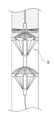
도 1은 본 발명의 일 실시예에 따른 고압수 및 고압공기를 이용한 상수도관 세척장치의 전체적인 개념도이며, 도 2는 본 발명의 다른 실시예에 따른 고압수 및 고압공기를 이용한 상수도관 세척장치의 전체적인 개념도이며, 도 3 내지 도 5는 도 2의 상수도관 세척장치 일부 구성의 상세도이며, 도 6과 도 7은 본 발명에 따른 고압수 및 고압공기를 이용한 상수도관 세척장치를 이용하여 세척을 하는 예시적인 모습이다.1 is an overall conceptual diagram of a water supply pipe cleaning apparatus using high pressure water and high pressure air according to an embodiment of the present invention, and FIG. 2 is a water supply pipe washing apparatus using high pressure water and high pressure air according to another embodiment of the present invention. 3 to 5 are detailed views of a part of the water pipe cleaning device of FIG. 2, and FIGS. 6 and 7 are a water pipe cleaning device using high pressure water and high pressure air according to the present invention. It is an exemplary look.
이하 도면을 참조하여 본 발명에 대해 상세히 설명하도록 한다.The present invention will be described in detail with reference to the drawings below.
본 발명의 상수도관 세척장치는 고압수와 고압공기를 후방에서 공급하여 상수도관 내부에 투입된 상수도관 세척장치를 전진시키면서 동시에 상수도관 내주면과 맞닿아서 서로 맞닿아서 회전하면서 녹과 슬러지를 제거하는 브러쉬의 회전력도 후방에서 공급되는 고압수의 압력을 이용하는 것이 특징이다. 이를 통해 별도의 전력 에너지를 사용하지 않게 된다. 본 발명의 세척장치는 세척을 요하는 상수도관의 일정 구역을 선정하고 상수도관 내부로 주입하게 된다. 그리고, 세척장치가 상수도관 내부에서 이동하면서 상수도관 내주면을 세척하는 장치다.The water supply pipe cleaning device of the present invention supplies high-pressure water and high-pressure air from the rear to advance the water pipe cleaning device introduced into the water pipe, while at the same time contacting the inner circumferential surface of the water pipe to rotate in contact with each other to remove rust and sludge The rotational force of the brush also uses the pressure of high-pressure water supplied from the rear. Through this, no separate power energy is used. The cleaning device of the present invention selects a certain area of the water supply pipe requiring cleaning and injects it into the water supply pipe. In addition, the cleaning device is a device that cleans the inner circumferential surface of the water supply pipe while moving inside the water supply pipe.
본 발명의 상수도관 세척장치(100)를 보면, 먼저 상수도관 내부에 투입된 상태에서 상수도관의 길이방향을 따라 배치되는 원통부재(110)를 구비한다. 상기 원통부재는 내부 중공인 중공부재일 수 있는데, 이것은 이하 설명할 바와 같이 외부에서 고압의 공기를 공급하는 통로 역할을 한다.Looking at the water supply
그리고, 상기 원통부재의 선단에는 우산형상인 피그로 원추형상부재(120)가 구비되는데, 이것은 중앙부가 전방으로 돌출되고 주변부가 후방에 위치하는 우산 형상이다. 본 발명의 설명에서 '전방'이라 함은 세척장치가 상수도관 내부에서 세척하면서 전진하는 방향을 의미하며, '후방'이라 함은 그 반대방향을 의미하는 것으로 한다. 그리고, 상기 원추형상부재의 후방에서 상기 원통부재에 결합되는 링 형상의 고정지지부재(130)와, 상기 원추형상부재의 주변부와 상기 고정지지부재를 서로 연결하여 상기 원추형상부재의 주변부를 지지하는 지지와이어(140)를 더 포함한다. 상기 지지와이어(140)는 원추형상부재를 후방에서 연결하여 원추형상부재가 후방에서 공급되는 고압수에 의해 전복되지 않도록 힘을 가하는 역할을 하게 된다.And, the front end of the cylindrical member is provided with a cone-shaped
상기 원추형상부재에는 복수 개의 분사구(125)가 형성되어 있다. 상기 분사구는 상기 원추형상부재의 전방과 후방을 연통시키는 통로 역할을 하는 것으로 비교적 작은 지름의 구멍으로 이루어진다. 세척과정에서 원추형상부재 후방으로 외부에서 고압수가 공급되는데, 원추형상부재의 후방의 고압수가 상기 분사구(125)를 통해서 전방으로 분사된다. 상기 복수 개의 분사구(125)는 일종의 고압수가 분사되는 노즐 역할을 하며, 노즐에서 분사되는 물이 이하 설명할 블레이드를 충격하여 블레이드를 회전하게 한다. 그림에서 C로 표시한 것은 세척장치의 전방과 후방에 설치되어 상수도관 전방 및 후방의 내부를 촬영할 수 있는 카메라이며, F로 표시한 것은 원추형상부재(120)를 접었다 폈다 할 수 있도록 하는 프레임이다. A plurality of
상기 원추형상부재의 전방에는 회전하는 블레이드(150)가 배치된다. 블레이드는 상기 원통부재에 회전가능하게 결합되고, 상기 분사구(125)에서 분사되는 고압수가 충돌하여 회전하게 된다. 그리고, 상기 블레이드의 전방에서 상기 원통부재에 회전가능하게 결합되되, 상기 블레이드와 일체로 연결되어 함께 회전하는 브러쉬(160)가 구비된다.A
위와 같이 구성된 본 발명의 세척장치를 이용하여 상수도관 내부를 세척하는 과정을 보면, 먼저 상수도관 내부에 본 발명의 세척장치를 투입한다. 그리고, 세척장치의 후방에서 고압의 물인 고압수를 공급한다. 피그로서 원추형상부재의 외주면은 상수도관 내주면과 맞닿는 정도의 직경을 가지도록 한다. 바람직하게는 원추형상부재(120)의 외주면에는 상기 상수도관 내주면과 맞닿도록 구비되는 접촉세척부재(128)를 더 포함하는 것이 좋다. 접촉세척부재는 적절한 소재의 재질로 이루어져서 상수도관 내주면과 맞닿아 미끌어지면서 세척할 수 있는 것이면 어떤 재질이나 형상이어도 좋다.Looking at the process of cleaning the inside of the water supply pipe using the cleaning device of the present invention configured as above, first, the cleaning device of the present invention is put into the water supply pipe. Then, high-pressure water, which is high-pressure water, is supplied from the rear of the cleaning device. As a pig, the outer circumferential surface of the conical member is to have a diameter that is in contact with the inner circumferential surface of the water supply pipe. Preferably, the outer circumferential surface of the
이 상태에서 상기 원통부재의 후방에서 공급되는 고압수는 상기 원추형상부재의 분사구를 통해 전방으로 분사되고, 분사구를 통해 분사된 고압수는 상기 블레이드를 충격하여 블레이드가 회전하게 한다. 그러면, 블레이드와 일체로 결합되어 함께 회전하는 브러쉬가 회전하면서 상수도관 내주면을 세척하게 된다.In this state, the high-pressure water supplied from the rear of the cylindrical member is injected forward through the nozzle of the conical member, and the high-pressure water injected through the nozzle impacts the blade to rotate the blade. Then, the brush that is integrally coupled with the blade and rotates together cleans the inner circumferential surface of the water supply pipe while rotating.
또한, 본 발명의 세척장치는 상기 원통부재(110)의 선단과 후단에 각각 결합되는 인출와이어(170)와 지지와이어(180)를 포함한다. 인출와이어(170)는 인출와이어 선단에 위치하는 부력부재(175)와 함께 세척과정이 마무리된 후 세척장치를 상수도관 외부로 인출하기 위한 와이어이고, 지지와이어(180)는 상기 세척장치의 이동속도를 조절하기 위해 후방에서 견인하는 와이어이다. 즉, 세척장치 후방에서 공급된 고압수에 의해 세척장치가 상수도관 내부에서 너무 빠른 속도로 이동하는 것을 방지하기 위해 적절한 힘으로 후방으로 당기면서 견인와이어를 풀어주게 되면 세척장치의 이동 속도를 제어할 수 있게 된다.In addition, the cleaning device of the present invention includes a
그리고, 상기 원통부재는 내부가 중공인 형상으로서, 상기 원통부재의 선단부 적절한 곳에는 내부 중공과 외부를 연통하도록 하는 공기분사구(미도시)가 형성될 수 있다. 상기 공기분사구는 바람직하게는 상기 원추형상부재와 블레이드 사이에 형성된다. 외부의 에어 공급수단에 의해 그리고 유연한 관을 이용하여 연결함으로써, 세척과정에 상기 원통부재의 내부 중공으로 고압의 공기를 공급할 수 있다. 이렇게 공급된 고압의 공기는 원추형상부재와 블레이드 사이에서 상기 공기분사구로 분사되어 상수도관 세척 효율을 더욱 높이게 된다.In addition, the cylindrical member has a hollow inside, and an air injection hole (not shown) may be formed at an appropriate place at the front end of the cylindrical member to communicate the inside hollow and the outside. The air injection port is preferably formed between the conical member and the blade. By connecting with an external air supply means and using a flexible pipe, high-pressure air can be supplied to the inner hollow of the cylindrical member during the cleaning process. The high-pressure air thus supplied is injected through the air nozzle between the conical member and the blade to further increase the efficiency of cleaning the water supply pipe.
도 2에서는 본 발명의 다른 실시예에 따른 세척장치를 도시하고 있다.2 shows a washing device according to another embodiment of the present invention.
본 실시예에 따른 세척장치는 일부 구성은 위에서 설명한 바와 유사하다. 즉, 상수도관 내부에서 상수도관 길이방향을 따라 배치되는 원통부재(210)와, 상기 원통부재의 선단에서 원통부재에 회전가능하게 결합되고, 중앙부가 전방으로 돌출되고 주변부가 후방에 위치하는 우산 형상의 원추형상부재(220)와, 상기 원추형상부재의 후방에서 상기 원통부재에 회전가능하게 결합되는 링 형상의 회전지지부재(230)와, 상기 원추형상부재의 주변부와 상기 회전지지부재를 서로 연결하여 상기 원추형상부재의 주변부를 지지하는 지지와이어(240)와, 상기 원추형상부재에 형성되어, 상기 원추형상부재의 전방과 후방을 연통시켜서 원추형상부재 후방의 고압수가 전방으로 분사되도록 하는 복수개의 분사구(225)와, 상기 원추형상부재의 전방에서 상기 원통부재에 회전가능하게 결합되고, 상기 원추형상부재와 함께 일체로 회전하도록 구비되는 브러쉬(260)와, 상기 원통부재의 선단과 후단에 각각 결합되는 인출와이어(270)와 지지와이어(280)를 포함한다.Some configurations of the cleaning device according to the present embodiment are similar to those described above. That is, a
본 실시예에서는 원추형상부재(220)에 형성된 분사구(225)에 의해, 원추형상부재 자체가 회전하는 것이 특징이다. 이를 위해 상기 분사구(225)는 전후방으로 직선형상으로 이루어지는 것이 아니라, 비스듬한 경사를 갖도록 형성된다. 즉, 상기 분사구(225)는 원추형상부재의 후방에서 전방으로 관통하도록 형성되되, 후방에서 전방으로 볼때 분사구의 형성방향이 좌우방향으로 비스듬히 형성된다.In this embodiment, it is characterized in that the conical member itself rotates by the
도 4는 도 3에 도시된 원추형상부재(220)의 측단면이며, 도 5는 도 3에 도시된 원추형상부재(220)를 우측면에서 바라본 모습이다. 도 4의 측단면을 보면 상기 분사구(225)는 원추형상부재의 전후방향으로 형성된다. 그러나, 전후 방향을 상수도관의 중심과 나란히 형성되는 것이 아니라, 비스듬히 형성되도록 한다. 즉, 도 5에 도시된 바와 같이, 원추형상부재(220)을 후방에서 전방으로 바라보면 상기 분사구(225)는 전방으로 가면서 좌우방향으로 경사지게 형성된다.4 is a cross-sectional side view of the
즉, 상기 분사구(225)는, 후방입구(225a)에서 전방입구(225b)를 갖되 이들 후방입구와 전방입구는 원추형상부재의 반경방향으로 어긋나게 형성된다. 이렇게 원추형상부재(220)의 분사구(225)가 후방에서 전방으로 가면서 좌우방향으로 경사지게 형성되기 때문에, 분사구를 관통하여 고압수가 통과하는 경우 원추형상부재(220)에 회전력을 가하게 되어 원추형상부재가 회전한다. 그 결과, 상기 원통부재에 회전가능하게 결합되고, 상기 원추형상부재와 함께 일체로 회전하도록 구비되는 브러쉬(260)가 회전하게 되어 상기 브러쉬가 상수도관의 내주면을 세척하게 된다.That is, the
본 발명은 이러한 구조에 의해, 세척을 요하는 상수도관 내부에 세척장치를 투입하고, 세척장치의 후방에서 즉, 상기 원통부재의 후방에서 고압수를 공급한다. 그러면, 상기 고압수는 상기 원추형상부재의 좌우방향으로 비스듬하게 형성된 분사구를 통해 전방으로 분사되고, 이 과정에서 상기 원추형상부재 및 상기 브러쉬가 함께 회전하고, 상기 브러쉬가 상수도관 내주면을 세척한다.According to the present invention, the cleaning device is inserted into the water supply pipe requiring cleaning, and high-pressure water is supplied from the rear of the cleaning device, that is, from the rear of the cylindrical member. Then, the high-pressure water is injected forward through a spray hole formed obliquely in the left and right directions of the conical member, and in this process, the conical member and the brush rotate together, and the brush cleans the inner circumferential surface of the water supply pipe.
그리고, 상기 원통부재는 내부가 중공인 형상이며, 상기 원통부재의 내부 중공과 외부를 연통하도록 하며, 상기 원추형상부재와 브러쉬 사이에 형성되는 공기분사구를 포함하여 고압의 공기를 분사하면서 상수도관 내부를 세척하는 것과, 상기 원추형상부재의 외주면에서 상기 상수도관 내주면과 맞닿도록 구비되는 접촉세척부재(228)를 더 포함하도록 하여 세척하는 것은 위에서 설명한 바와 같다. 그리고, 본 발명의 세척장치의 전방 내지 후방에 카메라(C)를 구비하여 상수도관 내부를 촬영하고 외부에서 세척이 이루어지기 전과 세척이 이루어진 후의 상태를 확인할 수 있도록 할 수 있다.In addition, the cylindrical member has a hollow shape on the inside, communicates the inner hollow of the cylindrical member with the outside, and includes an air nozzle formed between the conical member and the brush to inject high-pressure air into the water supply pipe. Washing and washing by further including a
본 발명에 따른 상수도관 세척 장치는 상기 구성에 의해서, 고압의 고압수의 압력을 이용하여 블레이드 날개를 회전시키고 이 회전력을 이용하여 브러쉬를 회전시켜서 상수도관 내주면을 물리적으로 세척하는 것으로 별도의 동력생성 장치를 요하지 않아 사용에 편리하면서 동시에 상수도관 내주면 세척 효과를 높인 장점이 있다. 다만, 구경이 400mm 이상의 상수도관은 추진노즐과 같은 동력장치를 추가하여 세척에 이용할 수 있다.According to the above configuration, the water supply pipe cleaning apparatus according to the present invention rotates the blade wings using the pressure of high pressure water and rotates the brush using this rotational force to physically clean the inner circumferential surface of the water supply pipe, thereby generating separate power It is convenient to use because it does not require a device, and at the same time, it has the advantage of increasing the cleaning effect of the inner surface of the water supply pipe. However, water supply pipes with a diameter of 400 mm or more can be used for washing by adding a power device such as a propulsion nozzle.
또한, 본 발명은 상수도관 세척장치를 이용하여 상수도관 내부를 세척하는 방법을 제공할 수도 있다. 본 발명에 따른 세척작업을 위해서는 먼저 일정 구간의 상수도관 밸브를 잠그고 작업을 하도록 한다. 그리고, 상수도관에 설치된 상수도관 세척작업구를 이용하여 상수도관 세척장치를 내부로 진입시켜 세척 작업전 상수도관의 상태를 촬영하고 나서, 본 발명에 따른 상수도관 세척장치를 이용하여 브러쉬를 회전시키면서 세척장치를 상수도관 내부에서 서서히 전진시키면서 세척이 이루어진다. 본 발명은 고압수를 후방에서 공급함으로써 세척장치의 전진에 필요한 힘을 얻고, 동시에 세척장치의 브러쉬 회전에 필요한 동력도 얻게 된다.In addition, the present invention may provide a method of cleaning the inside of the water supply pipe using the water supply pipe cleaning device. For the cleaning operation according to the present invention, first, the water supply pipe valve of a certain section is closed and the operation is performed. Then, by using the water supply pipe cleaning tool installed in the water supply pipe, the water supply pipe cleaning device enters the inside and the state of the water pipe before cleaning is photographed, and then the water pipe cleaning device according to the present invention is used to rotate the brush Cleaning is performed while the cleaning device is gradually advanced inside the water supply pipe. In the present invention, by supplying high-pressure water from the rear, power necessary for moving the cleaning device forward is obtained, and at the same time, power necessary for brush rotation of the cleaning device is obtained.
그리고, 상수도관 내벽의 스케일을 분리한 후 세척장치 전방에 위치하는 와이어(170)와 부력부재(175) 등을 이용하여 세척장치를 상수도관 외부로 인출한다. 그리고, 이후에는 하수도에 연결된 퇴수장치로 세척수를 배출하고 지상에 일정한 간격으로 설치되어 있는 소화전에 있는 고압수를 이용하여 상수도관 내벽에서 분리된 스케일을 상수도관 외부로 배출하게 된다. 이러한 과정을 통해, 본 발명의 세척장치는, 상수도관 내벽의 슬러지와 녹 등등의 스케일을 상수도관 내벽으로부터 분리시킨 후 세척장치를 상수도관 외부로 인출하게 된다. 이를 통해, 기존의 상수도관에 연결된 퇴수장치와 공공시설들인 소화전을 활용하여 추가 비용이 없이 상수도관 내벽 세척을 진행시킬 수 있는 장점을 제공하게 된다.Then, after the scale is separated from the inner wall of the water supply pipe, the washing device is drawn out of the water supply pipe using the
이상에서 본 발명의 바람직한 실시예에 대하여 상세하게 설명하였지만 본 발명의 권리범위는 이에 한정되는 것은 아니고 다음의 청구범위에서 정의하고 있는 본 발명의 기본 개념을 이용한 당업자의 여러 변형 및 개량 형태 또한 본 발명의 권리범위에 속하는 것이다.Although the preferred embodiments of the present invention have been described in detail above, the scope of the present invention is not limited thereto, and various modifications and improvements of those skilled in the art using the basic concept of the present invention defined in the following claims are also made according to the present invention. falls within the scope of the rights of
Claims (4)
Translated fromKorean상기 원통부재의 선단에 구비되고, 중앙부가 전방으로 돌출되고 주변부가 후방에 위치하는 우산 형상의 원추형상부재(120);
상기 원추형상부재의 후방에서 상기 원통부재에 결합되는 링 형상의 고정지지부재(130);
상기 원추형상부재의 주변부와 상기 고정지지부재를 서로 연결하여 상기 원추형상부재의 주변부를 지지하는 지지와이어(140);
상기 원추형상부재에 형성되어, 상기 원추형상부재의 전방과 후방을 연통시켜서 원추형상부재 후방의 고압수가 전방으로 분사되도록 하는 복수개의 분사구(125);
상기 원추형상부재의 전방에서 상기 원통부재에 회전가능하게 결합되고, 상기 분사구에서 분사되는 고압수가 충돌하여 회전하는 블레이드(150);
상기 블레이드의 전방에서 상기 원통부재에 회전가능하게 결합되고, 상기 블레이드와 함께 일체로 회전하도록 구비되는 브러쉬(160);
상기 원추형상부재의 외주면에서 상기 상수도관 내주면과 맞닿도록 구비되는 접촉세척부재(128); 및
상기 원통부재의 선단과 후단에 각각 결합되는 인출와이어(170)와 지지와이어(180);를 포함하고,
상수도관 내부에 투입된 상기 원통부재의 후방에서 공급되는 고압수가 상기 원추형상부재의 분사구를 통해 전방으로 분사됨에 따라 상기 블레이드 및 브러쉬가 회전하면서 상기 브러쉬가 상기 상수도관 내주면을 마찰하여 내부 슬러지와 녹을 제거하고, 상기 접촉세척부재가 상수도관 내주면을 닦으면서 세척이 이루어지고,
상기 원통부재는 내부가 중공인 형상이며,
상기 원통부재의 내부 중공과 외부를 연통하도록 하며, 상기 원추형상부재와 블레이드 사이에 형성되는 공기분사구;를 더 포함하고,
외부에서 상기 원통부재의 내부 중공으로 공급된 고압의 공기가 상기 공기분사구로 분사되어 상수도관 내주면을 세척하는 것을 특징으로 하는 상수도관 세척장치.A cylindrical member 110 disposed along the longitudinal direction of the water supply pipe inside the water supply pipe;
an umbrella-shaped conical member 120 provided at the front end of the cylindrical member, with a central portion protruding forward and a peripheral portion located at the rear;
A ring-shaped fixed support member 130 coupled to the cylindrical member at the rear of the conical member;
Support wire 140 for supporting the periphery of the conical member by connecting the periphery of the conical member and the fixed support member to each other;
a plurality of injection ports 125 formed on the conical member to communicate the front and rear surfaces of the conical member so that high-pressure water at the rear of the conical member is sprayed forward;
a blade 150 rotatably coupled to the cylindrical member in front of the conical member and rotated by colliding with the high-pressure water injected from the injection port;
a brush 160 rotatably coupled to the cylindrical member in front of the blade and integrally rotated together with the blade;
a contact cleaning member 128 provided so as to come into contact with the inner circumferential surface of the water supply pipe at the outer circumferential surface of the conical member; and
Including; a lead wire 170 and a support wire 180 coupled to the front and rear ends of the cylindrical member, respectively,
As the high-pressure water supplied from the rear of the cylindrical member injected into the water supply pipe is injected forward through the nozzle of the conical member, the blade and the brush rotate while the brush rubs the inner circumferential surface of the water supply pipe to remove internal sludge and rust And, the cleaning is performed while the contact cleaning member wipes the inner circumferential surface of the water supply pipe,
The cylindrical member has a hollow shape on the inside,
Further comprising an air injection port formed between the conical member and the blade to communicate the inner hollow of the cylindrical member with the outside,
Water supply pipe cleaning device, characterized in that the high-pressure air supplied from the outside to the inner hollow of the cylindrical member is sprayed through the air nozzle to clean the inner circumferential surface of the water supply pipe.
상기 원통부재의 선단에서 원통부재에 회전가능하게 결합되고, 중앙부가 전방으로 돌출되고 주변부가 후방에 위치하는 우산 형상의 원추형상부재(220);
상기 원추형상부재의 후방에서 상기 원통부재에 회전가능하게 결합되는 링 형상의 회전지지부재(230);
상기 원추형상부재의 주변부와 상기 회전지지부재를 서로 연결하여 상기 원추형상부재의 주변부를 지지하는 지지와이어(240);
상기 원추형상부재에 형성되어, 상기 원추형상부재의 전방과 후방을 연통시켜서 원추형상부재 후방의 고압수가 전방으로 분사되도록 하는 복수개의 분사구(225);
상기 원추형상부재의 전방에서 상기 원통부재에 회전가능하게 결합되고, 상기 원추형상부재와 함께 일체로 회전하도록 구비되는 브러쉬(260);
상기 원통부재의 선단과 후단에 각각 결합되는 인출와이어(270)와 지지와이어(280);를 포함하고,
상기 분사구(225)는
원추형상부재의 후방에서 전방으로 관통하도록 형성되되, 후방에서 전방으로 볼때 분사구의 형성방향이 좌우방향으로 비스듬히 형성되어 있어서,
상수도관 내부에 투입된 상기 원통부재의 후방에서 공급되는 고압수가 상기 원추형상부재의 좌우방향 비스듬한 분사구를 통해 전방으로 분사됨에 따라 상기 원추형상부재 및 상기 브러쉬가 회전하면서 상수도관 내주면을 세척하는 것을 특징으로 하는 상수도관 세척장치.A cylindrical member 210 disposed along the longitudinal direction of the water supply pipe inside the water supply pipe;
an umbrella-shaped conical member 220 rotatably coupled to the cylindrical member at the tip of the cylindrical member, with a central portion protruding forward and a peripheral portion located at the rear;
A ring-shaped rotation support member 230 rotatably coupled to the cylindrical member at the rear of the conical member;
Support wire 240 for supporting the periphery of the conical member by connecting the periphery of the conical member and the rotation support member to each other;
a plurality of injection ports 225 formed on the conical member to communicate the front and rear sides of the conical member so that high-pressure water at the rear of the conical member is sprayed forward;
a brush 260 rotatably coupled to the cylindrical member in front of the conical member and integrally rotated together with the conical member;
Including; a lead wire 270 and a support wire 280 coupled to the front and rear ends of the cylindrical member, respectively,
The nozzle 225 is
It is formed to penetrate from the rear to the front of the conical member, and when viewed from the rear to the front, the direction of formation of the injection hole is obliquely formed in the left and right directions,
As the high-pressure water supplied from the rear of the cylindrical member injected into the water pipe is sprayed forward through the left and right oblique spray holes of the conical member, the conical member and the brush rotate while washing the inner circumferential surface of the water pipe. water pipe cleaning device.
상기 원통부재는 내부가 중공인 형상이며,
상기 원통부재의 내부 중공과 외부를 연통하도록 하며, 상기 원추형상부재와 브러쉬 사이에 형성되는 공기분사구; 및
상기 원추형상부재의 외주면에서 상기 상수도관 내주면과 맞닿도록 구비되는 접촉세척부재(228);를 더 포함하고,
외부에서 상기 원통부재의 내부 중공으로 공급된 고압의 공기가 상기 공기분사구로 분사되어 상수도관 내주면을 세척하는 것을 특징으로 하는 상수도관 세척장치.According to claim 3,
The cylindrical member has a hollow shape on the inside,
an air injection port formed between the conical member and the brush so as to communicate the inner hollow of the cylindrical member with the outside; and
Further comprising a contact cleaning member 228 provided so as to come into contact with the inner circumferential surface of the water supply pipe at the outer circumferential surface of the conical member,
Water supply pipe cleaning device, characterized in that the high-pressure air supplied from the outside to the inner hollow of the cylindrical member is sprayed through the air nozzle to clean the inner circumferential surface of the water supply pipe.
Priority Applications (1)
| Application Number | Priority Date | Filing Date | Title |
|---|---|---|---|
| KR1020220104504AKR102528913B1 (en) | 2022-08-22 | 2022-08-22 | water pipe cleaning apparatus using high pressure water and air |
Applications Claiming Priority (1)
| Application Number | Priority Date | Filing Date | Title |
|---|---|---|---|
| KR1020220104504AKR102528913B1 (en) | 2022-08-22 | 2022-08-22 | water pipe cleaning apparatus using high pressure water and air |
Publications (1)
| Publication Number | Publication Date |
|---|---|
| KR102528913B1true KR102528913B1 (en) | 2023-05-04 |
Family
ID=86379463
Family Applications (1)
| Application Number | Title | Priority Date | Filing Date |
|---|---|---|---|
| KR1020220104504AActiveKR102528913B1 (en) | 2022-08-22 | 2022-08-22 | water pipe cleaning apparatus using high pressure water and air |
Country Status (1)
| Country | Link |
|---|---|
| KR (1) | KR102528913B1 (en) |
Cited By (2)
| Publication number | Priority date | Publication date | Assignee | Title |
|---|---|---|---|---|
| CN117123577A (en)* | 2023-10-20 | 2023-11-28 | 滨州泽郦精密金属科技有限公司 | Stainless steel pipe inner wall cleaning device |
| CN117732882A (en)* | 2024-02-07 | 2024-03-22 | 丽岛新能源(安徽)有限公司 | Roller structure of aluminum foil calender |
Citations (4)
| Publication number | Priority date | Publication date | Assignee | Title |
|---|---|---|---|---|
| KR101811277B1 (en) | 2017-01-05 | 2017-12-22 | 송태식 | Water pipe cleaning device of Spherical shape |
| KR101886572B1 (en)* | 2017-05-16 | 2018-08-07 | 천석현 | Pipe cleaning device |
| KR102150411B1 (en)* | 2019-06-18 | 2020-09-01 | 유현상 | Multi-function pipe cleaning device |
| KR102248298B1 (en)* | 2020-05-26 | 2021-05-06 | 주식회사 파워킹 | Apparatus for cleaning water pipe |
- 2022
- 2022-08-22KRKR1020220104504Apatent/KR102528913B1/enactiveActive
Patent Citations (4)
| Publication number | Priority date | Publication date | Assignee | Title |
|---|---|---|---|---|
| KR101811277B1 (en) | 2017-01-05 | 2017-12-22 | 송태식 | Water pipe cleaning device of Spherical shape |
| KR101886572B1 (en)* | 2017-05-16 | 2018-08-07 | 천석현 | Pipe cleaning device |
| KR102150411B1 (en)* | 2019-06-18 | 2020-09-01 | 유현상 | Multi-function pipe cleaning device |
| KR102248298B1 (en)* | 2020-05-26 | 2021-05-06 | 주식회사 파워킹 | Apparatus for cleaning water pipe |
Cited By (3)
| Publication number | Priority date | Publication date | Assignee | Title |
|---|---|---|---|---|
| CN117123577A (en)* | 2023-10-20 | 2023-11-28 | 滨州泽郦精密金属科技有限公司 | Stainless steel pipe inner wall cleaning device |
| CN117732882A (en)* | 2024-02-07 | 2024-03-22 | 丽岛新能源(安徽)有限公司 | Roller structure of aluminum foil calender |
| CN117732882B (en)* | 2024-02-07 | 2024-04-19 | 丽岛新能源(安徽)有限公司 | Roller structure of aluminum foil calender |
Similar Documents
| Publication | Publication Date | Title |
|---|---|---|
| KR100656095B1 (en) | Pipe washing machine using non-powered rotation | |
| KR102528913B1 (en) | water pipe cleaning apparatus using high pressure water and air | |
| KR102259539B1 (en) | water pipe cleaning apparatus using high pressure air | |
| KR102300901B1 (en) | water pipe cleaning apparatus using cleaning brush and method for cleaning using the same | |
| KR101811277B1 (en) | Water pipe cleaning device of Spherical shape | |
| US3080265A (en) | Process and apparatus for cleaning waste-disposal systems | |
| JP6514998B2 (en) | Drained vertical pipe cleaning apparatus comprising a nozzle cleaning apparatus for pipe cleaning and a nozzle cleaning apparatus for pipe cleaning | |
| KR100848177B1 (en) | Custom centering and painting centering device | |
| KR100815834B1 (en) | Centering device using non-rotating | |
| JPH11114513A (en) | High pressure jet cleaning equipment with camera for piping | |
| KR100325675B1 (en) | Apparatus for cleaning hard cohesion matters in waterworks and sewerage | |
| CN111119327A (en) | Pipe culvert dredging and pollution discharge method | |
| KR20220128573A (en) | water pipe cleaning apparatus using high pressure water, air and method for cleaning water pipe using the same | |
| KR20220123777A (en) | Water supply pipe cleaning device using forward and reverse rotation brushes while transporting with high pressure water and method for cleaning water supply pipe using the same | |
| JPH11179309A (en) | Cleaning device for existing pipeline | |
| KR102507159B1 (en) | Apparatus for Cleaning Pipe having rotating blade and Method for Cleaning Pipe Using the Same | |
| KR20200069620A (en) | High pressure water jet rotary nozzle for dredging sewage pipe | |
| CN110420942B (en) | Hose cleaner | |
| KR20220169302A (en) | water pipe cleaning apparatus by turning brush using high pressure water and method for cleaning water pipe using the same | |
| KR102588053B1 (en) | Apparatus for cleaning water pipe | |
| JP2006088002A (en) | Pipe inner surface cleaning device | |
| KR102658200B1 (en) | A pipe-line cleaning system | |
| JP3223974B2 (en) | Drain pipe cleaning method and apparatus | |
| KR100453520B1 (en) | Pipe washing apparatus | |
| KR100676446B1 (en) | Method and apparatus for cleaning drain pipe |
Legal Events
| Date | Code | Title | Description |
|---|---|---|---|
| PA0109 | Patent application | Patent event code:PA01091R01D Comment text:Patent Application Patent event date:20220822 | |
| PA0201 | Request for examination | ||
| PA0302 | Request for accelerated examination | Patent event date:20220822 Patent event code:PA03022R01D Comment text:Request for Accelerated Examination | |
| E902 | Notification of reason for refusal | ||
| PE0902 | Notice of grounds for rejection | Comment text:Notification of reason for refusal Patent event date:20230419 Patent event code:PE09021S01D | |
| E701 | Decision to grant or registration of patent right | ||
| PE0701 | Decision of registration | Patent event code:PE07011S01D Comment text:Decision to Grant Registration Patent event date:20230427 | |
| GRNT | Written decision to grant | ||
| PR0701 | Registration of establishment | Comment text:Registration of Establishment Patent event date:20230428 Patent event code:PR07011E01D | |
| PR1002 | Payment of registration fee | Payment date:20230428 End annual number:3 Start annual number:1 | |
| PG1601 | Publication of registration |