KR102528826B1 - Integrated camera lens suspension - Google Patents
Integrated camera lens suspensionDownload PDFInfo
- Publication number
- KR102528826B1 KR102528826B1KR1020177014694AKR20177014694AKR102528826B1KR 102528826 B1KR102528826 B1KR 102528826B1KR 1020177014694 AKR1020177014694 AKR 1020177014694AKR 20177014694 AKR20177014694 AKR 20177014694AKR 102528826 B1KR102528826 B1KR 102528826B1
- Authority
- KR
- South Korea
- Prior art keywords
- moving
- base layer
- metal base
- wire attachment
- support member
- Prior art date
- Legal status (The legal status is an assumption and is not a legal conclusion. Google has not performed a legal analysis and makes no representation as to the accuracy of the status listed.)
- Active
Links
Images


Classifications
- G—PHYSICS
- G02—OPTICS
- G02B—OPTICAL ELEMENTS, SYSTEMS OR APPARATUS
- G02B27/00—Optical systems or apparatus not provided for by any of the groups G02B1/00 - G02B26/00, G02B30/00
- G02B27/64—Imaging systems using optical elements for stabilisation of the lateral and angular position of the image
- G02B27/646—Imaging systems using optical elements for stabilisation of the lateral and angular position of the image compensating for small deviations, e.g. due to vibration or shake
- F—MECHANICAL ENGINEERING; LIGHTING; HEATING; WEAPONS; BLASTING
- F16—ENGINEERING ELEMENTS AND UNITS; GENERAL MEASURES FOR PRODUCING AND MAINTAINING EFFECTIVE FUNCTIONING OF MACHINES OR INSTALLATIONS; THERMAL INSULATION IN GENERAL
- F16F—SPRINGS; SHOCK-ABSORBERS; MEANS FOR DAMPING VIBRATION
- F16F1/00—Springs
- F16F1/02—Springs made of steel or other material having low internal friction; Wound, torsion, leaf, cup, ring or the like springs, the material of the spring not being relevant
- F16F1/025—Springs made of steel or other material having low internal friction; Wound, torsion, leaf, cup, ring or the like springs, the material of the spring not being relevant characterised by having a particular shape
- F16F1/027—Planar, e.g. in sheet form; leaf springs
- F—MECHANICAL ENGINEERING; LIGHTING; HEATING; WEAPONS; BLASTING
- F16—ENGINEERING ELEMENTS AND UNITS; GENERAL MEASURES FOR PRODUCING AND MAINTAINING EFFECTIVE FUNCTIONING OF MACHINES OR INSTALLATIONS; THERMAL INSULATION IN GENERAL
- F16F—SPRINGS; SHOCK-ABSORBERS; MEANS FOR DAMPING VIBRATION
- F16F15/00—Suppression of vibrations in systems; Means or arrangements for avoiding or reducing out-of-balance forces, e.g. due to motion
- F16F15/005—Suppression of vibrations in systems; Means or arrangements for avoiding or reducing out-of-balance forces, e.g. due to motion using electro- or magnetostrictive actuation means
- F—MECHANICAL ENGINEERING; LIGHTING; HEATING; WEAPONS; BLASTING
- F16—ENGINEERING ELEMENTS AND UNITS; GENERAL MEASURES FOR PRODUCING AND MAINTAINING EFFECTIVE FUNCTIONING OF MACHINES OR INSTALLATIONS; THERMAL INSULATION IN GENERAL
- F16M—FRAMES, CASINGS OR BEDS OF ENGINES, MACHINES OR APPARATUS, NOT SPECIFIC TO ENGINES, MACHINES OR APPARATUS PROVIDED FOR ELSEWHERE; STANDS; SUPPORTS
- F16M13/00—Other supports for positioning apparatus or articles; Means for steadying hand-held apparatus or articles
- F16M13/02—Other supports for positioning apparatus or articles; Means for steadying hand-held apparatus or articles for supporting on, or attaching to, an object, e.g. tree, gate, window-frame, cycle
- F16M13/022—Other supports for positioning apparatus or articles; Means for steadying hand-held apparatus or articles for supporting on, or attaching to, an object, e.g. tree, gate, window-frame, cycle repositionable
- G—PHYSICS
- G02—OPTICS
- G02B—OPTICAL ELEMENTS, SYSTEMS OR APPARATUS
- G02B7/00—Mountings, adjusting means, or light-tight connections, for optical elements
- G02B7/02—Mountings, adjusting means, or light-tight connections, for optical elements for lenses
- G—PHYSICS
- G02—OPTICS
- G02B—OPTICAL ELEMENTS, SYSTEMS OR APPARATUS
- G02B7/00—Mountings, adjusting means, or light-tight connections, for optical elements
- G02B7/02—Mountings, adjusting means, or light-tight connections, for optical elements for lenses
- G02B7/023—Mountings, adjusting means, or light-tight connections, for optical elements for lenses permitting adjustment
- G—PHYSICS
- G02—OPTICS
- G02B—OPTICAL ELEMENTS, SYSTEMS OR APPARATUS
- G02B7/00—Mountings, adjusting means, or light-tight connections, for optical elements
- G02B7/02—Mountings, adjusting means, or light-tight connections, for optical elements for lenses
- G02B7/04—Mountings, adjusting means, or light-tight connections, for optical elements for lenses with mechanism for focusing or varying magnification
- G02B7/08—Mountings, adjusting means, or light-tight connections, for optical elements for lenses with mechanism for focusing or varying magnification adapted to co-operate with a remote control mechanism
- G—PHYSICS
- G02—OPTICS
- G02B—OPTICAL ELEMENTS, SYSTEMS OR APPARATUS
- G02B7/00—Mountings, adjusting means, or light-tight connections, for optical elements
- G02B7/02—Mountings, adjusting means, or light-tight connections, for optical elements for lenses
- G02B7/04—Mountings, adjusting means, or light-tight connections, for optical elements for lenses with mechanism for focusing or varying magnification
- G02B7/09—Mountings, adjusting means, or light-tight connections, for optical elements for lenses with mechanism for focusing or varying magnification adapted for automatic focusing or varying magnification
- H—ELECTRICITY
- H05—ELECTRIC TECHNIQUES NOT OTHERWISE PROVIDED FOR
- H05K—PRINTED CIRCUITS; CASINGS OR CONSTRUCTIONAL DETAILS OF ELECTRIC APPARATUS; MANUFACTURE OF ASSEMBLAGES OF ELECTRICAL COMPONENTS
- H05K7/00—Constructional details common to different types of electric apparatus
- H05K7/14—Mounting supporting structure in casing or on frame or rack
- H05K7/1417—Mounting supporting structure in casing or on frame or rack having securing means for mounting boards, plates or wiring boards
- H—ELECTRICITY
- H05—ELECTRIC TECHNIQUES NOT OTHERWISE PROVIDED FOR
- H05K—PRINTED CIRCUITS; CASINGS OR CONSTRUCTIONAL DETAILS OF ELECTRIC APPARATUS; MANUFACTURE OF ASSEMBLAGES OF ELECTRICAL COMPONENTS
- H05K7/00—Constructional details common to different types of electric apparatus
- H05K7/14—Mounting supporting structure in casing or on frame or rack
- H05K7/1422—Printed circuit boards receptacles, e.g. stacked structures, electronic circuit modules or box like frames
- H—ELECTRICITY
- H05—ELECTRIC TECHNIQUES NOT OTHERWISE PROVIDED FOR
- H05K—PRINTED CIRCUITS; CASINGS OR CONSTRUCTIONAL DETAILS OF ELECTRIC APPARATUS; MANUFACTURE OF ASSEMBLAGES OF ELECTRICAL COMPONENTS
- H05K1/00—Printed circuits
- H05K1/02—Details
- H05K1/0277—Bendability or stretchability details
- H05K1/028—Bending or folding regions of flexible printed circuits
Landscapes
- Physics & Mathematics (AREA)
- Engineering & Computer Science (AREA)
- General Engineering & Computer Science (AREA)
- General Physics & Mathematics (AREA)
- Optics & Photonics (AREA)
- Mechanical Engineering (AREA)
- Microelectronics & Electronic Packaging (AREA)
- Aviation & Aerospace Engineering (AREA)
- Acoustics & Sound (AREA)
- Supporting Of Heads In Record-Carrier Devices (AREA)
- Adjustment Of Camera Lenses (AREA)
- Studio Devices (AREA)
- Lens Barrels (AREA)
- Sliding-Contact Bearings (AREA)
- Rolling Contact Bearings (AREA)
- Adjustment Of The Magnetic Head Position Track Following On Tapes (AREA)
Abstract
Translated fromKoreanDescription
Translated fromKorean관련 출원에 대한 상호 참조CROSS REFERENCES TO RELATED APPLICATIONS
본원은 이하의 미국 가출원의 이익 향유를 주장하고, 그 가출원 모두는 그 전체가 모든 목적을 위해서 본원에서 참조로 포함된다: 2014년 12월 2일자로 출원되고 명칭이 "광학적 화상 안정화(OIS) 카메라 렌즈 서스펜션에 대한 개선"인 제62/086,595호 및 2015년 3월 6일자로 출원되고 명칭이 "통합형 전기 리드를 가지는 2-단편 카메라 렌즈 서스펜션"인 제62/129,562호.This application claims the benefit of the following United States Provisional Applications, all of which are hereby incorporated by reference in their entirety for all purposes: Filed on December 2, 2014 and entitled "Optical Image Stabilization (OIS)
본 발명은 일반적으로 모바일 폰 내로 통합되는 것과 같은 카메라 렌즈 서스펜션(suspension)에 관한 것이다.The present invention generally relates to camera lens suspensions such as those incorporated into mobile phones.
PCT 국제출원공개 제WO 2014/083318호 및 제WO 2013/175197호는, 굴곡부 요소 또는 스프링 판에 의해서 정지적인 지지 조립체 상에서 지지되는 (카메라 렌즈 요소가 장착될 수 있는) 이동 조립체를 가지는 카메라 렌즈 광학적 화상 안정화기(OIS) 서스펜션 시스템을 개시한다. 이동 조립체는 복수의 볼에 의해서 지지 조립체 상에서 이동되도록 지지된다. 인청동과 같은 금속으로 형성되는 굴곡 요소는 이동 판 및 굴곡부를 갖는다. 굴곡부는 이동 판과 정지적인 지지 조립체 사이에서 연장되고 스프링으로서 역할하여, 정적인 지지 조립체에 대한 이동 조립체의 이동을 가능하게 한다. 볼은 이동 조립체가 작은 저항으로 이동될 수 있게 한다. 이동 조립체 및 지지 조립체는 그러한 조립체들 사이에서 연장되는 형상기억합금(SMA) 와이어에 의해서 결합된다. 각각의 SMA 와이어의 일 단부가 지지 조립체에 부착되고, 타 단부는 이동 조립체에 부착된다. 서스펜션은 전기 구동 신호를 SMA 와이어로 인가하는 것에 의해서 작동된다. 전술한 PCT 공개는 모든 목적을 위해서 본원에 참조로 포함된다.PCT International Application Publication Nos. WO 2014/083318 and WO 2013/175197 disclose camera lens optical components having a moving assembly (on which a camera lens element may be mounted) supported on a stationary support assembly by a flexion element or spring plate. An image stabilizer (OIS) suspension system is disclosed. The moving assembly is supported to be moved on the support assembly by a plurality of balls. A bending element formed of a metal such as phosphor bronze has a moving plate and a bending portion. The flexure extends between the moving plate and the stationary support assembly and acts as a spring, allowing movement of the moving assembly relative to the static support assembly. The ball allows the moving assembly to be moved with little resistance. The moving assembly and the support assembly are coupled by shape memory alloy (SMA) wires extending between the assemblies. One end of each SMA wire is attached to the support assembly and the other end is attached to the moving assembly. The suspension is operated by applying an electric drive signal to the SMA wire. The foregoing PCT publications are incorporated herein by reference for all purposes.
개선된 렌즈 서스펜션이 계속적으로 요구되고 있다. 고기능적이고, 비교적 얇거나 프로파일이 낮고, 강건하며, 제조가 효율적인 이러한 유형의 서스펜션 구조물이 특히 바람직할 것이다.There is a continuing need for improved lens suspensions. A suspension structure of this type that is highly functional, relatively thin or low profile, robust, and efficient to manufacture would be particularly desirable.
본 발명은 금속의 하나의 단편으로서 형성된 지지 금속 기저부 층을 포함하는 지지 부재, 및 금속의 하나의 단편으로서 형성된 이동 금속 기저부 층을 포함하는 이동 부재, 베어링, 및 스마트 기억 합금 와이어를 포함하는 개선된 서스펜션 조립체이다. 실시예에서, 지지 부재는 지지 금속 기저부 층 내의 베어링 판 부분 및 지지 금속 기저부 층 내의 정적 와이어 부착 구조물을 포함한다. 이동 부재는 이동 금속 기저부 층 내의 이동 판 부분, 이동 판 부분으로부터 연장되고 지지 부재에 결합되는, 이동 금속 기저부 층 내의 굴곡 아암, 및 이동 금속 기저부 층 내의 이동 와이어 부착 구조물을 포함한다. 이동 부재가 지지 부재에 대해서 이동할 수 있게 하기 위해서, 베어링이 지지 부재의 베어링 판 부분과 이동 부재의 이동 판 부분 사이에서 그들을 결합시킨다. 스마트 기억 합금 와이어는 지지 부재의 정적 와이어 부착 구조물과 이동 부재의 이동 와이어 부착 구조물에 부착되고 그 사이에서 연장된다.The present invention provides an improved support member comprising a supporting metal base layer formed as one piece of metal, and a moving member including a moving metal base layer formed as one piece of metal, a bearing, and a smart memory alloy wire. It is a suspension assembly. In an embodiment, the support member includes a bearing plate portion within the support metal base layer and a static wire attachment structure within the support metal base layer. The moving member includes a moving plate portion in the moving metal base layer, a flexing arm in the moving metal base layer extending from the moving plate portion and coupled to a support member, and a moving wire attachment structure in the moving metal base layer. To enable the moving member to move relative to the supporting member, a bearing engages them between the bearing plate portion of the supporting member and the moving plate portion of the moving member. The smart memory alloy wire is attached to and extends between the static wire attachment structure of the support member and the movable wire attachment structure of the movable member.
도 1a는 본 발명의 실시예에 따른 서스펜션의 상단 등각도를 도시한다.
도 1b는 도 1a에 도시된 서스펜션의 상단 평면도이다.
도 2a는 도 1a에 도시된 서스펜션의 지지 부재의 상단 등각도이다.
도 2b는 도 2a에 도시된 지지 부재의 하단 평면도이다.
도 3a는 도 2a에 도시된 지지 부재의 장착 영역의 구체적인 상단 등각도이다.
도 3b는 도 2a에 도시된 지지 부재의 장착 영역의 구체적인 하단 등각도이다.
도 4a는 도 1a에 도시된 서스펜션의 이동 부재의 상단 등각도이다.
도 4b는 도 4a에 도시된 이동 부재의 하단 평면도이다.
도 5는 도 4a에 도시된 이동 부재의 굴곡 아암 장착 영역 및 와이어 부착부의 구체적인 상단 등각도이다.
도 6은 도 4a에 도시된 이동 부재의 굴곡 아암 장착 영역 및 와이어 부착부의 구체적인 상단 등각도이다.
도 7은 도 1a에 도시된 서스펜션의 지지 부재 장착 영역 및 굴곡 아암 장착 영역의 구체적인 상단 등각도이다.
도 8은, 볼 베어링을 도시한, 도 1a에 도시된 서스펜션의 일부의 단면도이다.
도 9 내지 도 15는 서스펜션의 실시예의 주석을 기재한 도면이다.
도 16은 본 발명의 실시예에 따른 지지 부재의 주석을 기재한 도면이다.
도 17은 본 발명의 실시예에 따른 이동 부재의 주석을 기재한 도면이다.1A shows a top isometric view of a suspension according to an embodiment of the present invention.
FIG. 1B is a top plan view of the suspension shown in FIG. 1A.
FIG. 2A is an isometric top view of a support member of the suspension shown in FIG. 1A.
FIG. 2B is a bottom plan view of the support member shown in FIG. 2A.
FIG. 3A is a detailed top isometric view of the mounting area of the support member shown in FIG. 2A.
FIG. 3B is a detailed bottom isometric view of the mounting area of the support member shown in FIG. 2A.
FIG. 4A is a top isometric view of a movable member of the suspension shown in FIG. 1A.
Figure 4b is a bottom plan view of the moving member shown in Figure 4a.
FIG. 5 is a detailed isometric view of a top end of a bending arm mounting area and a wire attaching portion of the movable member shown in FIG. 4A.
FIG. 6 is a detailed isometric view of an upper end of a bending arm mounting region and a wire attachment portion of the movable member shown in FIG. 4A.
FIG. 7 is a detailed top isometric view of a support member mounting area and a flexion arm mounting area of the suspension shown in FIG. 1A.
8 is a cross-sectional view of a portion of the suspension shown in FIG. 1A showing ball bearings.
9 to 15 are annotated views of an embodiment of a suspension.
16 is an annotated view of a support member according to an embodiment of the present invention.
17 is a view describing annotations of a movable member according to an embodiment of the present invention.
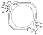
도 1a 및 도 1b는 본 발명의 실시예에 따른 서스펜션 조립체(10)를 도시한다. 도시된 바와 같이, 서스펜션 조립체(10)는 가요성 인쇄 회로(FPC) 또는 지지 부재(12) 및 지지 부재에 결합되는 스프링 크림프 회로(spring crimp circuit) 또는 이동 부재(14)를 포함한다. 스마트 기억 합금(SMA) 와이어(15)가 지지 부재(12)와 이동 부재(14) 사이에서 연장되고, 전기적으로 작동되어 지지 부재에 대한 이동 부재의 위치를 이동 및 제어할 수 있다. 실시예에서, 서스펜션 조립체(10)는 예를 들어, 모바일 폰, 태블릿, 랩탑 컴퓨터 내로 통합될 수 있는 카메라 렌즈 광학적 화상 안정화(OIS) 장치이다.1A and 1B show a
도 2a, 도 2b, 도 3a 및 도 3b는 지지 부재(12)를 더 구체적으로 도시한다. 도시된 바와 같이, 지지 부재(12)는 기저부 층(16), 및 기저부 층 상의 전도체 층 내의 트레이스(18a 내지 18d)와 같은 복수의 전도성 트레이스(18)를 포함한다. 유전체(20)의 층이 전도성 트레이스(18) 및 기저부 층(16) 사이에 위치되어, 트레이스를, 스테인리스 스틸과 같은 금속일 수 있는 기저부 층으로부터 전기적으로 절연시킨다. 크림프(24)(즉, 정적 크림프; 도시된 실시예에서 4개가 도시됨)와 같은 복수의 와이어 부착 구조물이 기저부 층(16) 상에 위치된다. 도시된 실시예에서, 크림프(24)는 기저부 층의 주요 평면형 표면 부분(26)으로부터 (예를 들어, z-방향으로) 이격된 준위에서 기저부 층(16) 내의 턱부(ledge)(25) 상에 일체로 형성된, 인접 구조물들의 2개의 쌍으로서 구성된다. 다른 실시예(미도시)는 다른 와이어 부착 구조물(예를 들어, 납땜 패드) 및/또는 (예를 들어, 쌍이 아니라 단독인) 다른 배열로 구성된 와이어 부착 구조물을 포함한다. 실시예에서, 베어링-유지 함몰부(28)가 기저부 층(16)의 부분(26) 내에 형성된다. 함몰부(28) 내의 베어링(도 8에 도시됨)이 이동 부재(14)와 결합될 수 있고 이동 부재를 지지 부재(12)에 대해서 이동 가능하게 지지할 수 있다. 트레이스(18)는 단자(30), 및 기저부 층(16) 상의 전도체 층 내의 접촉 패드(32)를 포함한다. 트레이스(18)의 각각이 단자(30)를 접촉 패드(32)에 결합시킨다. 예를 들어, 접촉 패드(32a 및 32b)는 지지 부재(12)의 제1 장착 영역(33)이고, 트레이스(18a 및 18b)는 단자(30a 및 30b)를 패드(32a 및 32b)에 각각 결합시킨다. 제2 장착 영역(35)에 위치되는 접촉 패드(32)가 유사하게 트레이스(18)에 의해서 단자(30)에 결합된다. 접촉 패드(32)는 도시된 실시예에서 각각의 크림프(24)에 위치되며, 접촉 패드의 각각은 별개의 트레이스에 의해서 별개의 단자(30)에 결합된다(예를 들어, 트레이스(18d)는 단자(30d)를 패드(32d)에 결합시킨다). 단자(30)가 위치되는 기저부 층(16)의 부분이 주요 표면 부분(26)의 평면을 벗어나(예를 들어, 도시된 실시예에서 주요 표면 부분의 평면에 수직으로) 형성된다. 도시된 실시예에서, 크림프(24)는 기저부 층(16)과 단일체이며, 표면 부분(26)과 같은 기저부 층의 동일한 재료의 단편으로 형성된다.2a, 2b, 3a and 3b show the
도 3a 및 도 3b는 지지 부재(12)의 장착 영역(33)의 실시예를 더 구체적으로 도시한다. 도시된 바와 같이, 장착 영역(33)은 제1 및 제2 장착 패드(40 및 42)를 포함한다. 장착 패드(42)는 기저부 층의 다른 부분으로부터 전기적으로 격리되는 기저부 층(16) 내의 섬 또는 패드 부분(44)을 포함한다. 섬 패드 부분(44)은 섬 패드 부분과 기저부 층의 인접 부분 사이에서 연장되는 유전체(20)의 지역에 의해서 기저부 층(16)의 인접 부분으로부터 부분적으로 지지될 수 있다. 트레이스(18a) 및 접촉 패드(32a)는 섬 패드 부분(44)까지 연장되고, 실시예에서, 장착 패드(42)에서 유전체(20)를 통해서 연장되는 도금된 또는 기타의 비아(46)와 같은 전기 연결부에 의해서 섬 패드 부분(44)에 전기적으로 연결된다. 다른 실시예는, 예를 들어, 유전체(20)의 연부 위에서 접촉 패드(32a)와 섬 패드 부분(44) 사이에서 연장되는 전도성 접착제와 같은 다른 전기 연결부를, 비아(46)를 대신하여 또는 비아에 부가적으로, 포함한다. 장착 패드(40)는 장착 패드(42)에 인접하고, 기저부 층(16) 내의 (실시예에서, 전기 접지 또는 공통 구조물로서 기능하는) 패드 부분(48), 및 접촉 패드(32b)를 패드 부분(48)에 연결하는 비아(50)와 같은 전기 연결부를 포함한다. 장착 영역(35)이 장착 영역(33)와 유사할 수 있다.3a and 3b show an embodiment of the mounting
도 4a, 도 4b, 도 5, 도 6 및 도 7은 이동 부재(14)의 실시예를 더 구체적으로 도시한다. 도시된 바와 같이, 이동 부재(14)는 판(60) 및 그러한 판(60)으로부터 연장되는 스프링 또는 굴곡 아암(62)을 포함한다. 도시된 실시예에서, 판(60)은 직사각형 부재이고, 각각의 굴곡 아암(62)은 판의 주연부의 2개의 측면을 따라서 연장되는 제1 및 제2 부분(64 및 66)을 가지는 세장형 부재이다. 도시된 실시예에서, 판(60) 및 굴곡 아암(62)은 스테인리스 스틸과 같은 스프링 금속 기저부 층(68)의 재료의 동일한 단편 내에 형성된다. 이동 부재(14)는 또한 크림프(70)(이동 크림프; 도시된 실시예에서 쌍으로 구성된 4개가 도시됨)와 같은 SMA 와이어 부착 구조물을 포함한다. 도시된 실시예에서, 크림프(70)는 판(60)과 단일체이며, 판과 같은 스프링 금속 기저부 층(68)의 동일한 단편으로(즉, 판으로부터 연장되는 아암(72)의 단부 상에) 형성된다. 이동 부재(14)는 다른 실시예에서 달리 구성된다. 예를 들어, 다른 실시예(미도시)에서, 굴곡 아암(62)이 달리 성형될 수 있고, 다른 개수일 수 있고, 달리 구성될 수 있고, 및/또는 판(60) 상의 다른 위치로부터 연장될 수 있다. 또 다른 실시예(미도시)에서, 크림프(70)는 판(60)에 부착된 별개의 구조물로서(즉, 판과 단일체가 아니게) 형성될 수 있다. 다른 실시예(미도시)는 다른 유형의 와이어 부착 구조물(예를 들어, 납땜 패드) 및/또는 다른 배열로 구성된(예를 들어, 쌍이 아니라 단독적으로 구성된) 와이어 부착 구조물을 포함한다.4a, 4b, 5, 6 and 7 show an embodiment of the moving
굴곡 아암(62)의 단부 부분은, 지지 부재(12)의 장착 영역(33 및 35)에 장착되도록 구성된 장착 영역(74)을 갖는다. 기저부 층(68) 상의 전도성 트레이스(76)는 굴곡 아암(62) 상에서 장착 영역(74)으로부터 연장된다. 실시예에서, 트레이스(76)는 또한 판(60)의 부분 위에서 기저부 층(68) 상에서 연장된다. 도시된 실시예에서, 트레이스(76)는 또한 판(60) 상의 아암(72) 상에서 접촉 패드(77)까지 연장된다. 도시된 실시예에서, 접촉 패드(77)는 판(60)의 주요 평면형 표면의 외부로 연장되는 플랫폼 상에 위치된다. 다른 실시예(미도시)에서, 접촉 패드는 다른 위치(예를 들어, 판(60) 상의 위치)에 위치된다. 유전체 층(78)이 전도성 트레이스(76) 및 기저부 층(68) 사이에 위치되어 기저부 층으로부터 트레이스를 전기적으로 절연시킨다. 장착 영역(74)은 제1 및 제2 장착 패드(80 및 82)를 포함한다. 각각의 장착 패드(82)는 기저부 층의 다른 부분으로부터 전기적으로 격리되는 기저부 층(68) 내의 섬 또는 패드 부분(84)을 포함한다. 각각의 트레이스(76)는 장착 패드(82)로부터, 장착 패드(80) 위로 (그리고 그로부터 전기적으로 절연되어) 연장된다. 도시된 실시예에서, 장착 패드들(80 및 82) 사이에서 연장되는 트레이스(76)의 부분이 굴곡 아암(62) 상의 트레이스의 부분 위에서 확대되어, 기저부 층(68) 내의 섬 패드 부분(84)을 위한 지지를 제공한다. 트레이스(76)는 섬 패드 부분(84)까지 연장되고, 실시예에서, 장착 패드(82)에서 유전체(78)를 통해서 연장되는 도금된 또는 기타의 비아(86)와 같은 전기 연결부에 의해서 섬 패드 부분에 전기적으로 연결된다. 다른 실시예는, 유전체(78)의 연부 위에서 트레이스(76)와 섬 패드 부분(84) 사이에서 연장되는 전도성 접착제와 같은 다른 전기 연결부를, 비아(86)를 대신하여 또는 비아에 부가적으로, 포함한다. 장착 패드(80)는 유전체(78)에 의해서 트레이스(76)으로부터 전기적으로 격리되는 기저부 층(68) 내의 패드 부분(90)을 포함한다. 도시된 실시예에서, 장착 패드(80 및 82) 위의 트레이스(76)의 부분이 원형이고 중심이 개방되나, 다른 실시예(미도시)에서 다른 형태를 취한다.An end portion of the
아마도 도 1a 및 도 7에 가장 잘 도시된 바와 같이, 이동 부재 굴곡 아암(62)의 장착 영역(74)은 지지 부재(12)의 장착 영역(33 및 35)에 기계적으로 부착된다. 굴곡 아암(62) 상의 트레이스(76)가 지지 부재(12) 상의 연관된 트레이스(18)에 전기적으로 연결된다. 실시예에서, 기계적 연결은 이동 부재(14)의 기저부 층(68) 내의 패드 부분(84 및 90)과 지지 부재(12)의 기저부 층(16) 내의 상응하는 패드 부분(44 및 48) 사이의 용접에 의해서 만들어진다. 용접은, 예를 들어, 패드 부분(84 및 90)에서의 트레이스(76) 내의 개구부를 통해서 만들어질 수 있다. 용접은 또한 이동 부재(14)의 패드 부분(84 및 90)과 지지 부재(12)의 상응하는 패드 부분(44 및 48) 사이의 전기 연결을 가능하게 한다. 이러한 전기 연결에 의해서, 이동 부재(14)의 금속 기저부 층(68), 및 그에 의해서 이동 크림프(70)가 연관된 트레이스(18)(즉, 예를 들어, 비아(50)를 통한 트레이스(18b))에 공통으로 전기적으로 연결된다. 유사하게, 각각의 굴곡 아암 트레이스(76)가 연관된 트레이스(18)(즉, 예를 들어, 비아(46)를 통한 트레이스(18a))에 전기적으로 연결된다. 본 발명의 다른 실시예(미도시)는 굴곡 아암(62)을 지지 부재(12)에 기계적으로 장착하기 위한, 및/또는 굴곡 아암 상의 트레이스(76)를 지지 부재의 연관된 트레이스(18) 상에 전기적으로 연결하기 위한 다른 구조물을 갖는다. 도시된 실시예에서, 크림프에 의해서 결합된 금속 기저부 층과 SMA 와이어(15) 사이의 전기 연결을 향상시키기 위해서, 전도성 금속 영역(94)은 크림프(70)에서 이동 부재(14)의 금속 기저부 층(68) 상에 직접적으로 위치된다(즉, 전도성 금속 영역과 금속 기저부 층 사이에는 유전체 또는 다른 절연 재료가 존재하지 않는다).As perhaps best shown in FIGS. 1A and 7 , the mounting
이하에서 더 구체적으로 설명되는 바와 같이, 지지 부재(12) 및 이동 부재(14)가 부가적인 및/또는 차감적인 프로세스로 형성될 수 있다. 실시예에서, 기저부 층(16 및/또는 68)은 스테인리스 스틸이다. 다른 실시예에서, 기저부 층(16 및/또는 68)은 인청동과 같은 다른 금속이나 재료이다. 트레이스(18 및 76), 단자(30) 및 접촉 패드(32)는 구리, 구리 합금, 또는 다른 전도체로 형성될 수 있다. 폴리이미드 또는 다른 절연 재료가 유전체(20 및 78)로서 사용될 수 있다. 지지 부재(12) 및/또는 이동 부재(14)의 다른 실시예(미도시)는 더 많거나 적은 트레이스(18 및 76)를 가지며, 트레이스가 다른 레이아웃으로 배열될 수 있다. 용접부와 같은, 크림프(24) 이외의 구조물을 이용하여 SMA 와이어(15)를 기저부 층(16)에 부착할 수 있다. 본 발명의 다른 실시예(미도시)는 더 많거나 적은 크림프(24 및 70)를 가지며, 크림프는 지지 부재(12) 및 이동 부재(14) 각각의 상부에서 상이한 위치에 있을 수 있다.As described in more detail below,
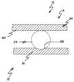
도 2a 및 도 2b에 도시된 지지 부재(12)의 실시예는 3개의 베어링 수용 함몰부(28)를 갖는다. 다른 실시예는 더 적거나 더 많은 베어링 함몰부를 갖는다. 도 8은, 함몰부(28) 중 하나 내에서, 볼 형태의, 베어링(29)을 도시하는, 서스펜션 조립체(10)의 일부의 도면이다. '29'와 같은 베어링이 다른 함몰부(28) 내에 유사하게 위치된다. 도시된 바와 같이, 베어링은 지지 부재(12)의 기저부 층(16)과 이동 부재(14)의 판(60)에 위치되는 기저부 층(68) 모두를 이동 가능하게 결합시켜, 이동 부재가 지지 부재에 대해서 이동될 수 있게 한다. 다른 실시예는 다른 베어링 구조물 및 구성(예를 들어, 판(60)의 기저부 층(68)으로부터 연장되는, 형성된 딤플을 포함한다)을 갖는다.The embodiment of the
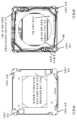
도 9 내지 도 15는 본 발명에 따른 개선된 카메라 렌즈 서스펜션 조립체의 주석을 기재한 도면이다. 서스펜션 조립체는 2개의 주요 구성요소 - (도 9 내지 도 15에서, 정적 FPC(가요성 인쇄 회로)로 지칭되는) 기저부 또는 지지 부재, 및 (도 9 내지 도 15에서, 스프링 크림프 회로로 지칭되는) 이동/스프링 부재를 갖는다. 정적 FPC(기저부 부재) 및 스프링 크림프 회로(이동 부재) 모두는, 기저부 금속(도시된 실시예에서 스테인리스 스틸(SST)) 상에 형성된 (예를 들어, 구리("Cu") 또는 구리 합금 층의) 리드, 접촉 패드, 및 단자와 같은 전기적 구조물을 갖는다는 점에서, 도시된 실시예에서 통합된 리드 구조물(integrated lead structure)이다. 절연체(예를 들어, 폴리이미드 또는 "폴리")의 층은, SST로부터 전기적으로 격리하고자 하는 전기적 구조물의 부분을 분리한다(Cu 층의 다른 부분은 SST 층에 연결되거나 그 층 상에 직접적으로 위치된다). 일부 위치에서, 전기적 구조물은, Cu 트레이스 또는 리드 층으로부터 폴리 층 내의 개구부를 통해서 SST 층까지 연장되는 전기 연결부(예를 들어, "비아")에 의해서, SST 층에 전기적으로 연결될 수 있다. 실시예에서, 렌즈가 스프링 크림프 회로에 장착될 수 있다. 또 다른 실시예에서, 렌즈를 지지하는 오토포커스 시스템이 스프링 크림프 회로에 장착될 수 있다.9-15 are annotated views of improved camera lens suspension assemblies in accordance with the present invention. The suspension assembly consists of two main components - a base or support member (referred to as a static FPC (Flexible Printed Circuit) in FIGS. 9-15 ) and a spring crimp circuit (referred to as a spring crimp circuit in FIGS. 9-15 ). It has a moving/spring member. Both the static FPC (base member) and spring crimp circuit (moving member) are formed on a base metal (stainless steel (SST) in the illustrated embodiment) (e.g., of copper ("Cu") or copper alloy layers). ) is an integrated lead structure in the illustrated embodiment, in that it has electrical structures such as leads, contact pads, and terminals. A layer of insulator (e.g., polyimide or "poly") separates the portion of the electrical structure that is to be electrically isolated from the SST (other portions of the Cu layer are connected to or directly on the SST layer). do). At some locations, electrical structures may be electrically connected to the SST layer by electrical connections (eg, “vias”) extending from the Cu traces or lead layers to the SST layer through openings in the poly layer. In an embodiment, a lens may be mounted to a spring crimp circuit. In another embodiment, the autofocus system supporting the lens may be mounted to the spring crimp circuit.
전술한 바와 같이, 정적 FPC 및 스프링 크림프 회로가 기저부 금속(예를 들어, SST와 같은 스프링 금속), 폴리 및 Cu(즉, "트레이스" 층)의 중첩되는 층으로 형성될 수 있다. 절연 커버코트가 Cu의 전부 또는 일부 위에 도포될 수 있다. 금(Au) 및/또는 니켈(Ni)과 같은 내식성 금속이 트레이스 층의 일부에 도금되거나 달리 도포되어 내식성을 제공할 수 있다. 통상적인 부가적 침착 프로세스 및/또는 습식(예를 들어, 화학적) 및 건식(예를 들어, 플라즈마) 식각과 같은 차감적 프로세스, 전기 도금 및 무전해 도금 그리고 포토리소그래피와 연관된 스퍼터링 프로세스(예를 들어, 패터닝된 및/또는 미패터닝 포토레지스트 마스크의 이용)뿐만 아니라, (예를 들어, 펀치 및 형틀 이용하는) 기계적 형성 방법을 이용하여 본 발명의 실시예에 따른 정적 FPC 및 스프링 크림프 회로를 제조할 수 있다. 이러한 유형의 부가적 및 차감적 프로세스가, 예를 들어, 디스크 드라이브 헤드 서스펜션의 제조와 관련하여 공지되어 있고 사용되고 있으며, 모든 목적을 위해서 본원에서 참조로서 전부가 포함되는 이하의 미국 특허에서 일반적으로 개시되어 있다: Bennin 등의 "이중 스테이지 작동 디스크 드라이브 서스펜션용 낮은 저항 접지 접합부"라는 명칭의 미국 특허 8,885,299, Rice 등의 "다중 트레이스 구성을 가지는 통합형 리드 서스펜션"이라는 명칭의 미국 특허 8,169,746, Hentges 등의 "통합형 리드 서스펜션을 위한 다중-층 접지 평면 구조물"이라는 명칭의 미국 특허 8,144,430, Hentges 등의 "통합형 리드 서스펜션을 위한 다중-층 접지 평면 구조물"이라는 명칭의 미국 특허 7,929,252, Swanson 등의 "서스펜션 조립체를 위한 귀금속 전도성 리드를 제조하기 위한 방법"이라는 명칭의 미국 특허 7,388,733, Peltoma 등의 "통합형 리드 서스펜션을 위한 도금된 접지 특징부"라는 명칭의 미국 특허 7,384,531.As discussed above, static FPC and spring crimp circuits may be formed from overlapping layers of base metal (eg spring metal such as SST), poly and Cu (ie "trace" layers). An insulating covercoat may be applied over all or part of the Cu. A corrosion-resistant metal, such as gold (Au) and/or nickel (Ni), may be plated or otherwise applied to portions of the trace layer to provide corrosion resistance. Conventional additive deposition processes and/or subtractive processes such as wet (eg chemical) and dry (eg plasma) etching, electroplating and electroless plating and sputtering processes associated with photolithography (eg , using patterned and/or unpatterned photoresist masks), as well as mechanical forming methods (eg, using punches and molds) to fabricate static FPCs and spring crimp circuits according to embodiments of the present invention. there is. Additive and subtractive processes of this type are known and used, for example, in connection with the manufacture of disk drive head suspensions, and are generally disclosed in the following US patents, which are hereby incorporated by reference in their entirety for all purposes. US Patent 8,885,299 entitled "Low Resistance Ground Junction for Dual Stage Actuated Disc Drive Suspension" by Bennin et al., US Patent 8,169,746 entitled "Integrated Lead Suspension with Multi-Trace Configuration" by Rice et al. US Patent 8,144,430, entitled "Multi-Layer Ground Plane Structure for Integrated Lid Suspension," US Patent 7,929,252 to Hentges et al., entitled "Multi-Layer Ground Plan Structure for Integrated Lid Suspension," Swanson et al. U.S. Patent No. 7,388,733, entitled "Method for Making Noble Metal Conductive Leads," and U.S. Patent 7,384,531, entitled "Plated Grounding Features for Integrated Reed Suspension," to Peltoma et al.
정적 FPC는 도시된 실시예에서 하나의-단편 부재이고, 부재의 2개의 대각선방향 모서리 상에서 2개의 정적 크림프(부착 구조물)를 갖는다(총 4개의 정적 크림프). 단자 패드 섹션은, 부재의 표면 위에서 연장되는 트레이스에 연결된 트레이스 층 내의 단자 패드를 포함한다. 예를 들어 도시된 바와 같이, 분리된 트레이스가 4개의 정적 크림프의 각각까지 연장된다. 정적 크림프의 각각에, 트레이스 층 및 폴리 층에 의해서 형성된 전기 접점 또는 단자가 위치된다. 정적 FPC 부재의 상부 표면으로부터 연장되는 형성된 딤플(formed dimple)이 스프링 크림프 회로 부재의 후방 표면과 결합되고, 활주 계면 베어링으로서 기능하여 정적 FPC에 대한 스프링 크림프 회로 부재의 저마찰 이동을 가능하게 한다. (예를 들어, 오토 포커스(AF) 조립체에 전기 신호를 제공하기 위해서 그리고 공통 또는 접지 신호 경로를 스프링 크림프 회로 부재의 SST 층에 제공하기 위해서) 정적 FPC 상의 트레이스는 또한 단자 패드를 스프링 크림프 회로 부재에 전기적 및 기계적으로 연결된 정적 FPC 상의 전기 패드 위치에 결합시킨다. 비아는 정적 FPC 상의 각각의 트레이스를 바닥부(feet)에 연결된 SST 층의 부분에 결합시킨다.The static FPC is a one-piece member in the illustrated embodiment and has two static crimps (attachment structures) on the two diagonal edges of the member (total of four static crimps). The terminal pad section includes terminal pads in the trace layer connected to traces extending over the surface of the member. For example, as shown, a separate trace extends to each of the four static crimps. On each of the static crimps are located electrical contacts or terminals formed by the trace layer and the poly layer. A formed dimple extending from the top surface of the static FPC member engages the rear surface of the spring crimp circuit member and functions as a sliding interface bearing to enable low-friction movement of the spring crimp circuit member relative to the static FPC. The traces on the static FPC also connect the terminal pads to the spring crimp circuit members (e.g., to provide electrical signals to the auto focus (AF) assembly and to provide a common or ground signal path to the SST layer of the spring crimp circuit members). to the electrical pad locations on the static FPC that are electrically and mechanically connected to A via couples each trace on the static FPC to the part of the SST layer connected to the feet.
스프링 크림프 회로는 도시된 실시예에서 하나의-단편 부재이고, 렌즈 또는 오토 포커스 시스템 및 중앙 부재로부터 연장되는 하나 이상의(도시된 실시예에서는 2개) 스프링 아암을 지지하기 위한 중앙 부재를 포함한다. 스프링 크림프 부재는 부재의 2개의 대각선 방향 모서리의 각각에서 2개의 이동 크림프를 갖는다(모두 4개의 이동 크림프). (도시된 실시예에서, 중앙 부재에 대향되는 스프링 아암의 단부 상의) SST 층 내의 받침대 또는 바닥부는 정적 FPC 상의 상응하는 위치에 용접되거나 달리 부착되도록 구성된다. 스프링 크림프 부재 상의 트레이스는 (예를 들어, 바닥부를 통해서) 정적 FPC 상의 트레이스에 전기적으로 결합되도록 구성되고, 신호를 오토 포커스(AF) 단자 패드와 같은 단자 패드에 결합시킨다. 도시된 실시예에서, 스프링 크림프 회로의 SST 층은 이동 크림프에 부착된 SMA 와이어의 단부로의 신호 경로로서 이용된다. 스프링 크림프 회로의 SST 층에 대한 정적 FPC 상의 트레이스와 상응하는 단자 패드 사이의 전기 연결부는 스프링 아암의 바닥부와 정적 FPC의 SST 층 사이의 연결에 의해서 제공된다(즉, 2개의 부재들의 SST 층들이 전기적으로 결합되고, 실시예에서 공통 접지 전위를 갖는다).The spring crimp circuit is a one-piece member in the illustrated embodiment and includes a central member for supporting the lens or autofocus system and one or more (in the illustrated embodiment two) spring arms extending from the central member. The spring crimp member has two moving crimps at each of the two diagonal edges of the member (all four moving crimps). The pedestal or bottom portion in the SST layer (in the illustrated embodiment, on the end of the spring arm opposite the central member) is configured to be welded or otherwise attached to a corresponding location on the static FPC. Traces on the spring crimp member are configured to be electrically coupled (eg, through the bottom) to traces on the static FPC, and couple signals to terminal pads, such as auto focus (AF) terminal pads. In the illustrated embodiment, the SST layer of the spring crimp circuit is used as a signal path to the end of the SMA wire attached to the moving crimp. The electrical connection between the trace on the static FPC to the SST layer of the spring crimp circuit and the corresponding terminal pad is provided by the connection between the bottom of the spring arm and the SST layer of the static FPC (i.e. the SST layers of the two members electrically coupled and, in an embodiment, have a common ground potential).
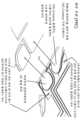
도 16은 본 발명의 실시예에 따른 통합형 베어링 판, 정적 크림프, 및 FPC를 가지는 '12'와 같은 지지 부재의 주석이 달린 도면이다. 도 17은 본 발명의 실시예에 따른 통합형 이동 크림프 및 스프링을 가지는 '14'와 같은 이동 부재의 주석이 달린 도면이다.16 is an annotated view of a support member such as '12' having integrated bearing plates, static crimps, and FPCs in accordance with an embodiment of the present invention. 17 is an annotated view of a moving member such as '14' having integrated moving crimps and springs in accordance with an embodiment of the present invention.
본 발명의 실시예에 따른 서스펜션은 중요한 장점을 제공한다. 그러한 서스펜션은, 예를 들어, 효율적으로 제조되고 조립될 수 있다. 서스펜션은 비교적 낮은 프로파일 또는 높이를 갖는다.Suspensions according to embodiments of the present invention provide important advantages. Such a suspension can be manufactured and assembled efficiently, for example. The suspension has a relatively low profile or height.
비록 본 발명이 바람직한 실시예를 참조하여 설명되었지만, 당업자는, 본 발명의 사상 및 범위로부터 벗어나지 않고도 형태 및 상세 부분에 대한 변화가 이루어질 수 있다는 것을 이해할 수 있을 것이다.Although the invention has been described with reference to preferred embodiments, those skilled in the art will appreciate that changes may be made in form and detail without departing from the spirit and scope of the invention.
Claims (26)
Translated fromKorean금속의 하나의 단편으로서 형성된 지지 금속 기저부 층을 포함하는 지지 부재로서:
상기 지지 금속 기저부 층 내의 베어링 판 부분; 및
상기 지지 금속 기저부 층 내의 정적 와이어 부착 구조물을 포함하는, 지지 부재;
금속의 하나의 단편으로서 형성된 이동 금속 기저부 층을 포함하고 상기 지지 부재에 장착되는 이동 부재로서:
상기 이동 금속 기저부 층 내의 이동 판 부분;
상기 이동 판 부분으로부터 연장되고 상기 지지 부재에 결합되는, 상기 이동 금속 기저부 층 내의 굴곡 아암; 및
상기 이동 금속 기저부 층 내의 이동 와이어 부착 구조물을 포함하는, 이동 부재;
상기 이동 부재가 상기 지지 부재에 대해서 이동할 수 있게 하기 위해서, 상기 지지 부재의 베어링 판 부분과 상기 이동 부재의 이동 판 부분 사이에서 그들과 결합되는 베어링; 및
상기 지지 부재의 정적 와이어 부착 구조물과 상기 이동 부재의 이동 와이어 부착 구조물에 부착되고 그 사이에서 연장되는 스마트 기억 합금 와이어
를 포함하는, 서스펜션 조립체.a suspension assembly,
A support member comprising a support metal base layer formed as one piece of metal comprising:
a bearing plate portion within the supporting metal base layer; and
a support member comprising a static wire attachment structure within the support metal base layer;
A movable member comprising a movable metal base layer formed as one piece of metal and mounted to the support member, comprising:
a moving plate portion within the moving metal base layer;
a flexure arm in the moving metal base layer extending from the moving plate portion and coupled to the support member; and
a moving member comprising a moving wire attachment structure in the moving metal base layer;
a bearing coupled between and between a bearing plate portion of the supporting member and a moving plate portion of the moving member, to enable the moving member to move relative to the supporting member; and
A smart memory alloy wire attached to the static wire attachment structure of the support member and the movable wire attachment structure of the movable member and extending therebetween.
Including, the suspension assembly.
상기 지지 부재가 복수의 정적 와이어 부착 구조물을 포함하고;
상기 이동 부재가 복수의 이동 와이어 부착 구조물을 포함하며; 그리고
상기 서스펜션은 복수의 스마트 기억 합금 와이어를 포함하고, 각각의 와이어는 상기 복수의 정적 와이어 부착 구조물 중 하나와 상기 복수의 이동 와이어 부착 구조물 중 하나에 부착되고 그 사이에서 연장되는, 서스펜션 조립체.According to claim 1,
the support member includes a plurality of static wire attachment structures;
the moving member includes a plurality of moving wire attachment structures; and
wherein the suspension includes a plurality of smart memory alloy wires, each wire attached to and extending between one of the plurality of static wire attachment structures and one of the plurality of moving wire attachment structures.
상기 지지 부재가 4개의 정적 와이어 부착 구조물을 포함하고;
상기 이동 부재가 4개의 이동 와이어 부착 구조물을 포함하고;
상기 서스펜션이 4개의 스마트 기억 합금 와이어를 포함하고;
상기 4개의 정적 와이어 부착 구조물은 인접한 정적 와이어 부착 구조물들의 2개의 쌍으로 배열되고, 상기 정적 와이어 부착 구조물의 쌍들이 제1 축을 중심으로 서로 이격되며; 그리고
상기 4개의 이동 와이어 부착 구조물은 인접한 이동 와이어 부착 구조물들의 2개의 쌍으로 배열되고, 상기 이동 와이어 부착 구조물의 쌍들이 제2 축을 중심으로 서로 이격되며, 상기 제2 축은 상기 제1 축에 수직인, 서스펜션 조립체.According to claim 2,
the support member includes four static wire attachment structures;
the moving member includes four moving wire attachment structures;
the suspension includes four smart memory alloy wires;
the four static wire attachment structures are arranged as two pairs of adjacent static wire attachment structures, and the pairs of static wire attachment structures are spaced apart from each other about a first axis; and
The four moving wire attachment structures are arranged in two pairs of adjacent moving wire attachment structures, the pairs of moving wire attachment structures are spaced apart from each other about a second axis, the second axis being perpendicular to the first axis, suspension assembly.
상기 정적 와이어 부착 구조물 및 상기 이동 와이어 부착 구조물이 크림프를 포함하는, 서스펜션 조립체.According to any one of claims 1 to 3,
wherein the static wire attachment structure and the moving wire attachment structure include crimps.
상기 지지 부재의 지지 금속 기저부 층 상에 인쇄 회로를 포함하는, 서스펜션 조립체.According to claim 1,
and a printed circuit on the support metal base layer of the support member.
상기 인쇄 회로가 상기 정적 와이어 부착 구조물까지 연장되는 트레이스를 포함하는, 서스펜션 조립체.According to claim 5,
wherein the printed circuit includes traces extending to the static wire attachment structure.
상기 베어링이 상기 지지 금속 기저부 층 내의 베어링 판 부분 및 상기 이동 금속 기저부 층 내의 이동 판 부분 모두와 이동 가능하게 결합되는, 서스펜션 조립체.According to any one of claims 1 to 3,
wherein the bearing is movably engaged with both a bearing plate portion in the support metal base layer and a movable plate portion in the movable metal base layer.
복수의 베어링을 더 포함하고, 각각의 베어링은 상기 지지 금속 기저부 층 내의 베어링 판 부분 및 상기 이동 금속 기저부 층 내의 이동 판 부분 모두와 이동 가능하게 결합되는, 서스펜션 조립체.According to any one of claims 1 to 3,
and further comprising a plurality of bearings, each bearing movably coupled with both a bearing plate portion in the supporting metal base layer and a moving plate portion in the moving metal base layer.
상기 베어링이 볼을 포함하는, 서스펜션 조립체.According to claim 7,
The suspension assembly of claim 1, wherein the bearing comprises a ball.
상기 이동 부재의 굴곡 아암은 상기 이동 판 부분의 주연부로부터 연장되는 세장형 부재인, 서스펜션 조립체.According to claim 1,
and the flexion arm of the moving member is an elongate member extending from a periphery of the moving plate portion.
상기 굴곡 아암은 상기 이동 판 부분에 대향되는 단부 상에 장착 영역을 포함하고;
상기 지지 부재의 베어링 판 부분이 장착 영역을 포함하며; 그리고
상기 굴곡 아암의 장착 영역이 상기 지지 부재의 장착 영역에 부착되고;
상기 굴곡 아암 각각은 유전체 상에 배치된 하나 이상의 전도성 트레이스를 포함하고, 상기 하나 이상의 전도성 트레이스는 상기 지지 부재 상의 하나 이상의 트레이스와 전기적으로 결합되는, 서스펜션 조립체.According to claim 10,
the flexion arm includes a mounting area on an end opposite to the moving plate portion;
a bearing plate portion of the support member includes a mounting area; and
the mounting area of the flexion arm is attached to the mounting area of the support member;
wherein each of the flexure arms includes one or more conductive traces disposed on a dielectric, the one or more conductive traces electrically coupled to one or more traces on the support member.
상기 굴곡 아암의 장착 영역을 상기 지지 부재의 장착 영역에 부착시키는 용접부를 더 포함하는, 서스펜션 조립체.According to claim 11,
and a weld attaching the mounting area of the flexure arm to the mounting area of the support member.
상기 굴곡 아암의 장착 영역이 상기 지지 부재의 장착 영역에 기계적 및 전기적으로 결합되는, 서스펜션 조립체.According to claim 11,
wherein the mounting area of the flexure arm is mechanically and electrically coupled to the mounting area of the support member.
금속의 하나의 단편으로서 형성된 지지 금속 기저부 층;
상기 지지 금속 기저부 층 내의 베어링 판 부분;
상기 지지 금속 기저부 층 내의 복수의 정적 와이어 부착 구조물, 선택적으로 크림프;
이동 부재의 굴곡 아암 장착 영역에 장착되도록 구성된, 지지 금속 기저부 층 상의 복수의 장착 영역; 및
각각의 정적 와이어 부착 구조물까지 연장되는 트레이스를 포함하는, 상기 지지 금속 기저부 층 상의 인쇄 회로
를 포함하는, 지지 부재.A support member for a suspension assembly of the type configured to have a moving member mounted to the support member, wherein:
a supporting metal base layer formed as one piece of metal;
a bearing plate portion within the supporting metal base layer;
a plurality of static wire attachment structures, optionally crimps, within the supporting metal base layer;
a plurality of mounting areas on the supporting metal base layer, configured to be mounted on flexure arm mounting areas of the moving member; and
printed circuitry on the supporting metal base layer, including traces extending to each of the static wire attachment structures;
Including, a support member.
금속의 하나의 단편으로서 형성되고, 상기 지지 부재에 장착되도록 구성된 이동 금속 기저부 층;
상기 이동 금속 기저부 층 내의 이동 판 부분;
상기 이동 판 부분의 주연부로부터 연장되고 상기 이동 판 부분에 대향하는 단부 상에 장착 영역을 포함하는, 상기 이동 금속 기저부 층 내의 복수의 세장형 굴곡 아암; 및
상기 이동 금속 기저부 층 내의 복수의 이동 와이어 부착 구조물, 선택적으로 크림프
를 포함하고,
스마트 기억 합금 와이어가 상기 지지 부재의 정적 와이어 부착 구조물과 상기 이동 와이어 부착 구조물에 부착되고 그 사이에서 연장되도록 구성되며,
상기 지지 부재 내의 베어링 판 부분과 상기 이동 부재의 이동 판 부분 사이에서 그들과 결합되는 베어링에 의해 상기 이동 부재가 상기 지지 부재에 대해서 이동할 수 있는, 이동 부재.A moving member for a suspension assembly of the type configured to have a support member mounted to the moving member, wherein:
a moving metal base layer formed as a piece of metal and configured to be mounted to the support member;
a moving plate portion within the moving metal base layer;
a plurality of elongated flexure arms in the moving metal base layer extending from a periphery of the moving plate portion and including a mounting region on an end opposite the moving plate portion; and
a plurality of moving wire attachment structures in the moving metal base layer, optionally crimps
including,
A smart memory alloy wire is configured to be attached to and extend between the static wire attachment structure and the mobile wire attachment structure of the support member,
The moving member, wherein the moving member is movable relative to the supporting member by a bearing coupled thereto between a bearing plate portion in the supporting member and a moving plate portion of the moving member.
Applications Claiming Priority (5)
| Application Number | Priority Date | Filing Date | Title |
|---|---|---|---|
| US201462086595P | 2014-12-02 | 2014-12-02 | |
| US62/086,595 | 2014-12-02 | ||
| US201562129562P | 2015-03-06 | 2015-03-06 | |
| US62/129,562 | 2015-03-06 | ||
| PCT/US2015/062576WO2016089685A1 (en) | 2014-12-02 | 2015-11-25 | Integrated camera lens suspension |
Publications (2)
| Publication Number | Publication Date |
|---|---|
| KR20170090425A KR20170090425A (en) | 2017-08-07 |
| KR102528826B1true KR102528826B1 (en) | 2023-05-08 |
Family
ID=56079116
Family Applications (3)
| Application Number | Title | Priority Date | Filing Date |
|---|---|---|---|
| KR1020177014694AActiveKR102528826B1 (en) | 2014-12-02 | 2015-11-25 | Integrated camera lens suspension |
| KR1020177014695AActiveKR102529554B1 (en) | 2014-12-02 | 2015-11-25 | Camera lens suspension with polymer bearings |
| KR1020177014693AActiveKR102529654B1 (en) | 2014-12-02 | 2015-12-02 | Ball-bearing retainers |
Family Applications After (2)
| Application Number | Title | Priority Date | Filing Date |
|---|---|---|---|
| KR1020177014695AActiveKR102529554B1 (en) | 2014-12-02 | 2015-11-25 | Camera lens suspension with polymer bearings |
| KR1020177014693AActiveKR102529654B1 (en) | 2014-12-02 | 2015-12-02 | Ball-bearing retainers |
Country Status (6)
| Country | Link |
|---|---|
| US (9) | US9366879B1 (en) |
| EP (5) | EP3605201B1 (en) |
| JP (4) | JP6721588B2 (en) |
| KR (3) | KR102528826B1 (en) |
| CN (4) | CN111638603A (en) |
| WO (3) | WO2016089699A1 (en) |
Families Citing this family (60)
| Publication number | Priority date | Publication date | Assignee | Title |
|---|---|---|---|---|
| GB201412848D0 (en) | 2014-07-18 | 2014-09-03 | Cambridge Mechatronics Ltd | Suspension system for a camera lens element |
| US9366879B1 (en) | 2014-12-02 | 2016-06-14 | Hutchinson Technology Incorporated | Camera lens suspension with polymer bearings |
| KR101825731B1 (en)* | 2014-12-04 | 2018-03-23 | 에이에이씨 어쿠스틱 테크놀로지스(심천)컴퍼니 리미티드 | Camera lens module with structure for optical image stabilization |
| US9454016B1 (en) | 2015-03-06 | 2016-09-27 | Hutchinson Technology Incorporated | Camera lens suspension with integrated electrical leads |
| KR102386998B1 (en)* | 2015-07-30 | 2022-04-15 | 엘지디스플레이 주식회사 | Supporter Pin And Heat Treatment Apparatus Comprising The Same |
| GB201517202D0 (en) | 2015-09-29 | 2015-11-11 | Cambridge Mechatronics Ltd | OIS actuator improvements |
| US11187916B2 (en) | 2015-10-28 | 2021-11-30 | Cambridge Mechatronics Limited | Camera assembly providing optical image stabilization |
| SG11201807830UA (en)* | 2016-03-11 | 2018-10-30 | Apple Inc | Optical image stabilization with voice coil motor for moving image sensor |
| US11956544B2 (en) | 2016-03-11 | 2024-04-09 | Apple Inc. | Optical image stabilization with voice coil motor for moving image sensor |
| US10670878B2 (en) | 2016-05-19 | 2020-06-02 | Hutchinson Technology Incorporated | Camera lens suspensions |
| CN107462964A (en)* | 2016-06-06 | 2017-12-12 | 新科实业有限公司 | Assembly method of SMA component and OIS device |
| JP6923563B2 (en)* | 2016-06-09 | 2021-08-18 | ハッチンソン テクノロジー インコーポレイテッドHutchinson Technology Incorporated | Shape memory alloy wire mounting structure with adhesive for suspension assembly |
| CN107664895B (en)* | 2016-07-29 | 2020-06-09 | 台湾东电化股份有限公司 | Lens driving device |
| CN111522183B (en)* | 2016-07-29 | 2021-12-31 | 台湾东电化股份有限公司 | Lens driving device |
| US10802242B2 (en)* | 2016-08-22 | 2020-10-13 | Hutchinson Technology Incorporated | Camera lens suspension with enhanced auto focus electrical interconnects |
| KR20190039581A (en)* | 2016-08-24 | 2019-04-12 | 허친슨 테크놀로지 인코포레이티드 | Dual camera assembly with optical image stabilization |
| CN107795966B (en)* | 2016-08-30 | 2023-06-02 | 广州市浩洋电子股份有限公司 | Optical element's rotary device and have its stage lamp optical device |
| US11521785B2 (en) | 2016-11-18 | 2022-12-06 | Hutchinson Technology Incorporated | High density coil design and process |
| US11387033B2 (en) | 2016-11-18 | 2022-07-12 | Hutchinson Technology Incorporated | High-aspect ratio electroplated structures and anisotropic electroplating processes |
| JP7657546B2 (en) | 2016-11-18 | 2025-04-07 | ハッチンソン テクノロジー インコーポレイテッド | High aspect ratio electroplated structures and anisotropic electroplating processes |
| US12147059B2 (en) | 2016-12-16 | 2024-11-19 | Hutchinson Technology Incorporated | Sensor shift structures in optical image stabilization suspensions |
| US11199182B2 (en) | 2016-12-16 | 2021-12-14 | Hutchinson Technology Incorporated | Sensor shift structures in optical image stabilization suspensions |
| US10397478B2 (en) | 2017-01-04 | 2019-08-27 | Hutchinson Technology Incorporated | Bearing limiter structures in optical image stabilization suspensions |
| US10890734B1 (en) | 2017-03-29 | 2021-01-12 | Apple Inc. | Camera actuator for lens and sensor shifting |
| KR101806245B1 (en)* | 2017-04-06 | 2017-12-07 | 성우전자 주식회사 | OIS Module and the Manufacturing Method of the Same |
| GB201707542D0 (en)* | 2017-05-11 | 2017-06-28 | Cambridge Mechatronics Ltd | Compact SMA shutter actuator |
| IT201700074728A1 (en)* | 2017-07-04 | 2019-01-04 | Actuator Solutions GmbH | Camera module auto-focus actuator |
| US10863094B2 (en) | 2017-07-17 | 2020-12-08 | Apple Inc. | Camera with image sensor shifting |
| CN208999737U (en)* | 2017-10-19 | 2019-06-18 | 台湾东电化股份有限公司 | Optical drive mechanism |
| GB201717855D0 (en)* | 2017-10-30 | 2017-12-13 | Cambridge Mechatronics Ltd | SMA actuator bearings |
| GB2608572B (en) | 2018-01-22 | 2023-07-19 | Cambridge Mechatronics Ltd | Shape memory alloy actuation apparatus |
| CN115145017B (en)* | 2018-01-25 | 2023-12-22 | 台湾东电化股份有限公司 | Optical system |
| CN108174104A (en)* | 2018-01-31 | 2018-06-15 | 上海信迈电子科技有限公司 | Anti-shake structure, anti-shake system and camera device having the same |
| US11638353B2 (en)* | 2018-09-17 | 2023-04-25 | Hutchinson Technology Incorporated | Apparatus and method for forming sensors with integrated electrical circuits on a substrate |
| US11873564B2 (en) | 2018-10-02 | 2024-01-16 | Hutchinson Technology Incorporated | Etch chemistry for metallic materials |
| US11340418B2 (en)* | 2018-12-27 | 2022-05-24 | Tdk Taiwan Corp. | Optical member driving mechanism |
| JP2020166179A (en) | 2019-03-29 | 2020-10-08 | 日本電産サンキョー株式会社 | Optical unit |
| WO2021000160A1 (en)* | 2019-06-30 | 2021-01-07 | 瑞声光学解决方案私人有限公司 | Lens module |
| US11503211B2 (en)* | 2019-08-16 | 2022-11-15 | Hutchinson Technology Incorporated | Stabilization suspensions and methods of manufacture |
| CN110568696A (en)* | 2019-09-30 | 2019-12-13 | 上海信迈电子科技有限公司 | Lens motor reed, lens motor, and image pickup apparatus |
| CN112698462B (en) | 2019-10-18 | 2024-12-27 | 新思考电机有限公司 | Optical component driving device, camera device, and electronic device |
| CN110780508B (en)* | 2019-11-22 | 2025-04-11 | 河南皓泽电子股份有限公司昆山分公司 | SMA actuator, camera module and electronic device |
| CN110764215A (en)* | 2019-11-22 | 2020-02-07 | 东莞市亚登电子有限公司 | SMA actuation mechanism, camera module, and electronic apparatus |
| GB201917543D0 (en)* | 2019-12-02 | 2020-01-15 | Cambridge Mechatronics Ltd | Actuator assembly |
| CN112904640B (en)* | 2019-12-03 | 2025-04-22 | 新思考电机有限公司 | Optical component driving device, camera device, and electronic device |
| CN111182194A (en)* | 2020-03-13 | 2020-05-19 | 厦门新鸿洲精密科技有限公司 | Triaxial anti-shake voice coil motor structure |
| WO2021229228A1 (en)* | 2020-05-13 | 2021-11-18 | Cambridge Mechatronics Limited | A shape memory alloy actuator assembly and a method of manufacturing thereof |
| CN111556239B (en)* | 2020-05-25 | 2022-03-22 | 维沃移动通信有限公司 | Photographing device, electronic device and control method |
| CN212211175U (en)* | 2020-06-23 | 2020-12-22 | 新思考电机有限公司 | OIS motor drive structure, OIS motor, camera device |
| CN114200739A (en) | 2020-09-02 | 2022-03-18 | 哈钦森技术股份有限公司 | Guided autofocus assembly |
| US11194115B1 (en) | 2020-09-02 | 2021-12-07 | Hutchinson Technology Incorporated | Guided autofocus assembly |
| US11575835B2 (en) | 2020-09-24 | 2023-02-07 | Apple Inc. | Multi-axis image sensor shifting system |
| US11932948B2 (en) | 2020-10-28 | 2024-03-19 | Hutchinson Technology Incorporated | Electroless nickel etch chemistry, method of etching and pretreatment |
| CN112213837B (en)* | 2020-12-08 | 2021-02-09 | 常州市瑞泰光电有限公司 | Lens driving device |
| US12356071B2 (en)* | 2020-12-18 | 2025-07-08 | Tdk Taiwan Corp. | Optical element driving mechanism |
| GB2602627B (en)* | 2020-12-31 | 2023-06-07 | Cambridge Mechatronics Ltd | Actuator assemblies |
| TWI759114B (en) | 2021-01-20 | 2022-03-21 | 大陽科技股份有限公司 | Optical image stabilizer, camera module and electronic device |
| WO2023002182A1 (en)* | 2021-07-20 | 2023-01-26 | Cambridge Mechatronics Limited | Actuator assembly |
| DE102021126358B3 (en) | 2021-10-12 | 2023-03-16 | Lpkf Laser & Electronics Aktiengesellschaft | Optical image stabilizer and mobile device equipped therewith and method of manufacture |
| US12231753B1 (en) | 2022-09-07 | 2025-02-18 | Apple Inc. | Flexure arm separator for flexure module of camera with moveable image sensor |
Citations (4)
| Publication number | Priority date | Publication date | Assignee | Title |
|---|---|---|---|---|
| JP2012502323A (en) | 2008-09-12 | 2012-01-26 | ケンブリッジ メカトロニクス リミテッド | Optical image stabilization |
| US20120019675A1 (en) | 2009-02-09 | 2012-01-26 | Andrew Benjamin David Brown | Optical image stabilisation |
| WO2013175197A1 (en) | 2012-05-25 | 2013-11-28 | Cambridge Mechatronics Limited | Shape memory alloy actuation apparatus |
| WO2014083318A1 (en)* | 2012-11-27 | 2014-06-05 | Cambridge Mechatronics Limited | Suspension system for a camera lens element |
Family Cites Families (109)
| Publication number | Priority date | Publication date | Assignee | Title |
|---|---|---|---|---|
| CH457131A (en) | 1967-09-06 | 1968-05-31 | Koch Carl | Photographic focusing screen camera |
| US3776447A (en) | 1969-06-30 | 1973-12-04 | Texas Instruments Inc | Automatic semiconductor bonding machine |
| US3734386A (en) | 1971-06-30 | 1973-05-22 | Ibm | Wiring apparatus with wire path forming means |
| US4140265A (en) | 1975-06-26 | 1979-02-20 | Kollmorgen Technologies Corporation | Method and apparatus for positioning the end of a conductive filament at a predetermined and repeatable geometric location for coupling to a predetermined terminal area of an element |
| JPS5698900A (en) | 1980-01-07 | 1981-08-08 | Hitachi Ltd | Device for automatically wiring printed circuit board |
| JPS57201739U (en) | 1981-06-19 | 1982-12-22 | ||
| JPS59104565U (en) | 1982-12-29 | 1984-07-13 | 日本メクトロン株式会社 | flexible circuit board |
| DE3672530D1 (en) | 1985-05-31 | 1990-08-16 | Dynapert Delvotec Sa | CONNECTING HEAD. |
| US5743654A (en)* | 1987-05-29 | 1998-04-28 | Kmc, Inc. | Hydrostatic and active control movable pad bearing |
| JPS6473754A (en) | 1987-09-16 | 1989-03-20 | Nec Corp | Manufacture of lead frame for semiconductor device |
| JPH01186577A (en) | 1988-01-13 | 1989-07-26 | Shin Nippon Koki Kk | Connector connection tool |
| US4984581A (en) | 1988-10-12 | 1991-01-15 | Flexmedics Corporation | Flexible guide having two-way shape memory alloy |
| JPH0358464A (en) | 1989-07-26 | 1991-03-13 | Nec Corp | Semiconductor device |
| JPH05283146A (en) | 1992-03-31 | 1993-10-29 | Toshiba Lighting & Technol Corp | Thick film resistance heating element |
| US5269810A (en) | 1992-06-19 | 1993-12-14 | W. L. Gore & Associates, Inc. | Patch electrode |
| JP2959322B2 (en) | 1993-03-09 | 1999-10-06 | 住友電装株式会社 | Harness electric wire manufacturing apparatus and manufacturing method |
| JPH06275325A (en) | 1993-03-24 | 1994-09-30 | Mitsubishi Electric Home Appliance Co Ltd | Connecting structure for conducting wire |
| WO1994024704A1 (en) | 1993-04-12 | 1994-10-27 | Bolger Justin C | Area bonding conductive adhesive preforms |
| JPH07259725A (en) | 1994-03-17 | 1995-10-09 | Olympus Optical Co Ltd | Flexible tube curing device |
| DE19549174A1 (en) | 1995-10-28 | 1997-07-03 | Bosch Gmbh Robert | Contact element with crimp section |
| US5831820A (en) | 1996-12-30 | 1998-11-03 | Huang; James | Peripheral docking module using a shape memory alloy actuator wire |
| US6149742A (en) | 1998-05-26 | 2000-11-21 | Lockheed Martin Corporation | Process for conditioning shape memory alloys |
| JP3488100B2 (en) | 1998-10-13 | 2004-01-19 | 矢崎総業株式会社 | Automatic cutting and crimping equipment |
| US6574958B1 (en) | 1999-08-12 | 2003-06-10 | Nanomuscle, Inc. | Shape memory alloy actuators and control methods |
| US6639411B1 (en) | 2000-09-05 | 2003-10-28 | Hutchinson Technology Incorporated | Microactuated suspension motor failure detection system |
| JP2002130114A (en) | 2000-10-20 | 2002-05-09 | Toshiba Corp | Actuator device |
| WO2002057627A1 (en) | 2001-01-17 | 2002-07-25 | M 2 Medical A/S | Shape memory alloy actuator |
| JP4406707B2 (en) | 2001-06-06 | 2010-02-03 | ソニー株式会社 | Two-axis device for optical disk device |
| JP4278364B2 (en) | 2002-11-08 | 2009-06-10 | パイオニア株式会社 | Actuator for pickup device |
| US6916115B1 (en) | 2003-03-04 | 2005-07-12 | University Of Kentucky Research Foundation | System and device for characterizing shape memory alloy wires |
| JP2007528506A (en)* | 2004-02-06 | 2007-10-11 | コーニンクレッカ フィリップス エレクトロニクス エヌ ヴィ | Camera device, mobile phone having camera device, and method of manufacturing camera device |
| JP2005227365A (en) | 2004-02-10 | 2005-08-25 | Sony Corp | Method for manufacturing optical component |
| US7384531B1 (en) | 2004-02-19 | 2008-06-10 | Hutchinson Technology Incorporated | Plated ground features for integrated lead suspensions |
| JP2007537562A (en) | 2004-05-14 | 2007-12-20 | ハッチンソン テクノロジー インコーポレーティッド | Method for producing noble metal conductive lead for suspension assembly |
| US7679647B2 (en)* | 2004-07-21 | 2010-03-16 | Hewlett-Packard Development Company, L.P. | Flexible suspension for image stabilization |
| KR100725341B1 (en) | 2004-08-12 | 2007-06-07 | 가부시키가이샤 무라타 세이사쿠쇼 | Piezoelectric Acoustic Transducer |
| JP4186907B2 (en)* | 2004-10-14 | 2008-11-26 | ソニー株式会社 | Electronics |
| JP2007092556A (en) | 2005-09-27 | 2007-04-12 | Konica Minolta Opto Inc | Drive device and its manufacturing method |
| US7777782B2 (en)* | 2005-11-04 | 2010-08-17 | Nokia Corporation | Stabilization of an image produced by optics |
| JP4737756B2 (en) | 2006-02-27 | 2011-08-03 | Necトーキン株式会社 | Solid electrolytic capacitor |
| WO2007113478A1 (en) | 2006-03-30 | 2007-10-11 | 1...Limited | Camera lens actuation apparatus |
| GB0606425D0 (en) | 2006-03-30 | 2006-05-10 | 1 Ltd | Camera lens actuation apparatus |
| US8175449B2 (en) | 2006-05-30 | 2012-05-08 | Konica Minolta Opto, Inc. | Driving device, driving mechanism, and image sensing apparatus |
| US7650914B2 (en) | 2006-06-22 | 2010-01-26 | Autosplice, Inc. | Apparatus and methods for filament crimping and manufacturing |
| US7832082B1 (en) | 2006-10-10 | 2010-11-16 | Hutchinson Technology Incorporated | Method for manufacturing an integrated lead suspension component |
| US7929252B1 (en) | 2006-10-10 | 2011-04-19 | Hutchinson Technology Incorporated | Multi-layer ground plane structures for integrated lead suspensions |
| JP4816397B2 (en) | 2006-10-12 | 2011-11-16 | 住友電気工業株式会社 | Photoelectric conversion module |
| JP5562648B2 (en) | 2007-01-29 | 2014-07-30 | スパイナル・モデュレーション・インコーポレイテッド | Non-stitched top retaining mechanism |
| GB2467481B (en) | 2007-02-12 | 2011-03-23 | Cambridge Mechatronics Ltd | Shape memory alloy actuation apparatus |
| GB0702676D0 (en) | 2007-02-12 | 2007-03-21 | 1 Ltd | Method of driving a shape memory alloy actuator |
| GB0702835D0 (en)* | 2007-02-14 | 2007-03-28 | Johnson Electric Sa | Lens module |
| JP2008233526A (en) | 2007-03-20 | 2008-10-02 | Tamron Co Ltd | Actuator for preventing image shake and camera equipped therewith |
| US7974025B2 (en) | 2007-04-23 | 2011-07-05 | Cambridge Mechatronics Limited | Shape memory alloy actuation apparatus |
| EP2140138B1 (en) | 2007-04-23 | 2012-04-11 | Cambridge Mechatronics Limited | Shape memory alloy actuation apparatus |
| JP5194622B2 (en) | 2007-08-02 | 2013-05-08 | コニカミノルタアドバンストレイヤー株式会社 | Drive mechanism, drive device, and lens drive device |
| CN101408655B (en) | 2007-10-11 | 2011-07-27 | 鸿富锦精密工业(深圳)有限公司 | Lens module |
| JP5101984B2 (en) | 2007-10-23 | 2012-12-19 | セイコーインスツル株式会社 | Drive module |
| JP4355742B2 (en) | 2007-10-31 | 2009-11-04 | 三菱電機エンジニアリング株式会社 | Short-circuit plate |
| KR20090081855A (en) | 2008-01-25 | 2009-07-29 | 이-핀 옵티칼 인더스트리 컴퍼니 리미티드 | Lens Displacement Mechanism Using Shape Memory Alloy |
| US8388773B2 (en) | 2008-03-07 | 2013-03-05 | GM Global Technology Operations LLC | Apparatus for and method of conditioning shape memory alloy wire |
| US8169746B1 (en) | 2008-04-08 | 2012-05-01 | Hutchinson Technology Incorporated | Integrated lead suspension with multiple trace configurations |
| EP2302434A4 (en) | 2008-07-11 | 2012-03-14 | Seiko Instr Inc | DRIVE MODULE, ASSEMBLY METHOD THEREFOR, AND ELECTRONIC APPARATUS |
| JP2010128262A (en) | 2008-11-28 | 2010-06-10 | Mitsumi Electric Co Ltd | Lens drive unit and connection method |
| US8441749B2 (en) | 2009-02-09 | 2013-05-14 | Cambridge Mechatronics Limited | Shape memory alloy actuation apparatus |
| JP2010192036A (en) | 2009-02-18 | 2010-09-02 | Funai Electric Co Ltd | Objective lens actuator |
| CN102356508B (en) | 2009-03-16 | 2016-04-13 | 永备电池有限公司 | Oxygen-consuming batteries with improved high-rate performance |
| JP5348241B2 (en) | 2009-03-25 | 2013-11-20 | コニカミノルタ株式会社 | Actuator, drive device, and imaging device |
| CN101876742A (en) | 2009-04-28 | 2010-11-03 | 三美电机株式会社 | Lens driver |
| JP4804564B2 (en)* | 2009-07-14 | 2011-11-02 | キヤノン株式会社 | Optical apparatus having shake correction device |
| JP2011039485A (en)* | 2009-07-14 | 2011-02-24 | Seiko Instruments Inc | Drive module and electronic device |
| JP5846346B2 (en) | 2009-08-21 | 2016-01-20 | ミツミ電機株式会社 | Camera shake correction device |
| JP2011107413A (en) | 2009-11-17 | 2011-06-02 | Morioka Seiko Instruments Inc | Actuator, drive module, and electronic equipment |
| JP2011175160A (en) | 2010-02-25 | 2011-09-08 | Mitsumi Electric Co Ltd | Lens driving device |
| WO2011104518A1 (en) | 2010-02-26 | 2011-09-01 | Cambridge Mechatronics Limited | Sma actuation apparatus |
| US9999763B2 (en) | 2012-06-13 | 2018-06-19 | Mainstay Medical Limited | Apparatus and methods for anchoring electrode leads adjacent to nervous tissue |
| US8885299B1 (en) | 2010-05-24 | 2014-11-11 | Hutchinson Technology Incorporated | Low resistance ground joints for dual stage actuation disk drive suspensions |
| JP2012032470A (en) | 2010-07-29 | 2012-02-16 | Sony Corp | Lens module and camera |
| US9137429B2 (en) | 2010-08-09 | 2015-09-15 | Cambridge Mechatronics Limited | Camera apparatus |
| US8866918B2 (en) | 2010-09-22 | 2014-10-21 | Cambridge Mechatronics Limited | Optical image stabilisation |
| GB201019532D0 (en) | 2010-11-18 | 2010-12-29 | Cambridge Mechatronics Ltd | Optical image stablisation drive |
| CN103502138A (en) | 2010-11-22 | 2014-01-08 | 空气传感公司 | Method for wafer level integration of shape memory alloy wires |
| US8851443B2 (en) | 2010-12-15 | 2014-10-07 | Autosplice, Inc. | Memory alloy-actuated apparatus and methods for making and using the same |
| JP5821356B2 (en) | 2011-07-15 | 2015-11-24 | ミツミ電機株式会社 | Lens drive device |
| KR101920502B1 (en)* | 2011-12-29 | 2018-11-20 | 존슨 일렉트릭 에스.에이. | Bearing holder and actuator |
| JP2013178457A (en) | 2012-02-01 | 2013-09-09 | Seiko Instruments Inc | Drive module and electronic apparatus |
| US9288394B2 (en)* | 2012-02-01 | 2016-03-15 | Ricoh Imaging Company, Ltd. | Stage apparatus and camera shake correction apparatus |
| GB2514071B (en) | 2012-02-16 | 2015-09-16 | Cambridge Mechatronics Ltd | Shape memory alloy actuation apparatus |
| KR20130098635A (en) | 2012-02-28 | 2013-09-05 | 삼성전자주식회사 | Capillary exchange system of semiconductor wire bond |
| GB201206490D0 (en) | 2012-04-12 | 2012-05-30 | Cambridge Mechatronics Ltd | Compact camera |
| JP2013238848A (en)* | 2012-04-20 | 2013-11-28 | Hoya Corp | Imaging apparatus |
| JP5967366B2 (en) | 2012-09-11 | 2016-08-10 | Smk株式会社 | Flat shape memory cable body and driving device using the same |
| GB201220485D0 (en) | 2012-11-14 | 2012-12-26 | Cambridge Mechatronics Ltd | Control of an SMA actuation apparatus |
| KR102401035B1 (en)* | 2012-12-20 | 2022-05-24 | 애플 인크. | Actuator module, camera module, multifunction device, systems and method for voice coil motor optical image stabilization |
| JP2014225378A (en) | 2013-05-16 | 2014-12-04 | 株式会社日立製作所 | Sealant for tab lead, tab lead and lithium ion secondary battery |
| KR101569345B1 (en) | 2013-07-25 | 2015-11-16 | 크루셜텍 (주) | Actuator Using Shape Memory Alloy Wire |
| US9277789B2 (en) | 2013-09-10 | 2016-03-08 | Texas Instruments Incorporated | Current, temperature or electromagnetic field actuated fasteners |
| CN105793761B (en) | 2013-09-12 | 2018-09-11 | 剑桥机电有限公司 | The insulation of sma actuator line in micro-camera |
| JP2015128267A (en) | 2013-12-27 | 2015-07-09 | セイコーエプソン株式会社 | Vibrating piece, vibrator, oscillator, electronic device, sensor and moving body |
| GB201403803D0 (en) | 2014-03-04 | 2014-04-16 | Cambridge Mechatronics Ltd | SMA actuator |
| GB201412848D0 (en) | 2014-07-18 | 2014-09-03 | Cambridge Mechatronics Ltd | Suspension system for a camera lens element |
| US9366879B1 (en) | 2014-12-02 | 2016-06-14 | Hutchinson Technology Incorporated | Camera lens suspension with polymer bearings |
| US9454016B1 (en) | 2015-03-06 | 2016-09-27 | Hutchinson Technology Incorporated | Camera lens suspension with integrated electrical leads |
| JP6447819B2 (en) | 2015-03-10 | 2019-01-09 | セイコーエプソン株式会社 | Head and liquid ejecting apparatus |
| KR102519325B1 (en) | 2015-04-02 | 2023-04-10 | 허친슨 테크놀로지 인코포레이티드 | Wire transport and attachment system for camera lens suspension |
| GB201517202D0 (en) | 2015-09-29 | 2015-11-11 | Cambridge Mechatronics Ltd | OIS actuator improvements |
| US11187916B2 (en) | 2015-10-28 | 2021-11-30 | Cambridge Mechatronics Limited | Camera assembly providing optical image stabilization |
| US10670878B2 (en) | 2016-05-19 | 2020-06-02 | Hutchinson Technology Incorporated | Camera lens suspensions |
| JP6923563B2 (en) | 2016-06-09 | 2021-08-18 | ハッチンソン テクノロジー インコーポレイテッドHutchinson Technology Incorporated | Shape memory alloy wire mounting structure with adhesive for suspension assembly |
| CN111405743B (en)* | 2019-01-03 | 2023-09-05 | 新科实业有限公司 | Suspension assembly of optical image stabilizer |
- 2015
- 2015-11-24USUS14/951,051patent/US9366879B1/enactiveActive
- 2015-11-25KRKR1020177014694Apatent/KR102528826B1/enactiveActive
- 2015-11-25CNCN202010580844.3Apatent/CN111638603A/enactivePending
- 2015-11-25WOPCT/US2015/062713patent/WO2016089699A1/enactiveApplication Filing
- 2015-11-25JPJP2017529018Apatent/JP6721588B2/enactiveActive
- 2015-11-25WOPCT/US2015/062576patent/WO2016089685A1/enactiveApplication Filing
- 2015-11-25EPEP19193083.3Apatent/EP3605201B1/enactiveActive
- 2015-11-25JPJP2017529039Apatent/JP6692356B2/enactiveActive
- 2015-11-25USUS14/951,573patent/US9541769B2/enactiveActive
- 2015-11-25KRKR1020177014695Apatent/KR102529554B1/enactiveActive
- 2015-11-25EPEP15864743.8Apatent/EP3227746B1/enactiveActive
- 2015-11-25CNCN201580065890.7Apatent/CN107003538B/enactiveActive
- 2015-11-25CNCN201580065775.XApatent/CN107003537B/enactiveActive
- 2015-11-25EPEP15866032.4Apatent/EP3227748B1/enactiveActive
- 2015-11-25EPEP19173490.4Apatent/EP3557313B1/enactiveActive
- 2015-12-02USUS14/956,612patent/US10775638B2/enactiveActive
- 2015-12-02CNCN201580065332.0Apatent/CN107003536B/enactiveActive
- 2015-12-02KRKR1020177014693Apatent/KR102529654B1/enactiveActive
- 2015-12-02EPEP15865383.2Apatent/EP3227747B1/enactiveActive
- 2015-12-02JPJP2017529044Apatent/JP6715247B2/enactiveActive
- 2015-12-02WOPCT/US2015/063363patent/WO2016089956A1/enactiveApplication Filing
- 2016
- 2016-05-17USUS15/156,545patent/US10139647B2/enactiveActive
- 2017
- 2017-01-06USUS15/400,516patent/US10067357B2/enactiveActive
- 2018
- 2018-08-31USUS16/119,619patent/US10969602B2/enactiveActive
- 2018-11-26USUS16/200,570patent/US11073702B2/enactiveActive
- 2020
- 2020-04-14JPJP2020072465Apatent/JP7288879B2/enactiveActive
- 2021
- 2021-04-05USUS17/222,144patent/US11635631B2/enactiveActive
- 2021-07-26USUS17/385,806patent/US11977241B2/enactiveActive
Patent Citations (4)
| Publication number | Priority date | Publication date | Assignee | Title |
|---|---|---|---|---|
| JP2012502323A (en) | 2008-09-12 | 2012-01-26 | ケンブリッジ メカトロニクス リミテッド | Optical image stabilization |
| US20120019675A1 (en) | 2009-02-09 | 2012-01-26 | Andrew Benjamin David Brown | Optical image stabilisation |
| WO2013175197A1 (en) | 2012-05-25 | 2013-11-28 | Cambridge Mechatronics Limited | Shape memory alloy actuation apparatus |
| WO2014083318A1 (en)* | 2012-11-27 | 2014-06-05 | Cambridge Mechatronics Limited | Suspension system for a camera lens element |
Also Published As
Similar Documents
| Publication | Publication Date | Title |
|---|---|---|
| KR102528826B1 (en) | Integrated camera lens suspension | |
| US9454016B1 (en) | Camera lens suspension with integrated electrical leads |
Legal Events
| Date | Code | Title | Description |
|---|---|---|---|
| PA0105 | International application | St.27 status event code:A-0-1-A10-A15-nap-PA0105 | |
| R17-X000 | Change to representative recorded | St.27 status event code:A-3-3-R10-R17-oth-X000 | |
| PG1501 | Laying open of application | St.27 status event code:A-1-1-Q10-Q12-nap-PG1501 | |
| E13-X000 | Pre-grant limitation requested | St.27 status event code:A-2-3-E10-E13-lim-X000 | |
| P11-X000 | Amendment of application requested | St.27 status event code:A-2-2-P10-P11-nap-X000 | |
| P13-X000 | Application amended | St.27 status event code:A-2-2-P10-P13-nap-X000 | |
| PA0201 | Request for examination | St.27 status event code:A-1-2-D10-D11-exm-PA0201 | |
| P22-X000 | Classification modified | St.27 status event code:A-2-2-P10-P22-nap-X000 | |
| E902 | Notification of reason for refusal | ||
| PE0902 | Notice of grounds for rejection | St.27 status event code:A-1-2-D10-D21-exm-PE0902 | |
| P11-X000 | Amendment of application requested | St.27 status event code:A-2-2-P10-P11-nap-X000 | |
| P13-X000 | Application amended | St.27 status event code:A-2-2-P10-P13-nap-X000 | |
| E701 | Decision to grant or registration of patent right | ||
| PE0701 | Decision of registration | St.27 status event code:A-1-2-D10-D22-exm-PE0701 | |
| PR0701 | Registration of establishment | St.27 status event code:A-2-4-F10-F11-exm-PR0701 | |
| PR1002 | Payment of registration fee | St.27 status event code:A-2-2-U10-U12-oth-PR1002 Fee payment year number:1 | |
| PG1601 | Publication of registration | St.27 status event code:A-4-4-Q10-Q13-nap-PG1601 |