KR102528715B1 - Medical snare apparatus - Google Patents
Medical snare apparatusDownload PDFInfo
- Publication number
- KR102528715B1 KR102528715B1KR1020200141566AKR20200141566AKR102528715B1KR 102528715 B1KR102528715 B1KR 102528715B1KR 1020200141566 AKR1020200141566 AKR 1020200141566AKR 20200141566 AKR20200141566 AKR 20200141566AKR 102528715 B1KR102528715 B1KR 102528715B1
- Authority
- KR
- South Korea
- Prior art keywords
- snare
- present
- catching
- guide
- snare device
- Prior art date
- Legal status (The legal status is an assumption and is not a legal conclusion. Google has not performed a legal analysis and makes no representation as to the accuracy of the status listed.)
- Active
Links
Images


Classifications
- A—HUMAN NECESSITIES
- A61—MEDICAL OR VETERINARY SCIENCE; HYGIENE
- A61B—DIAGNOSIS; SURGERY; IDENTIFICATION
- A61B17/00—Surgical instruments, devices or methods
- A61B17/32—Surgical cutting instruments
- A61B17/3205—Excision instruments
- A61B17/32056—Surgical snare instruments
- A—HUMAN NECESSITIES
- A61—MEDICAL OR VETERINARY SCIENCE; HYGIENE
- A61B—DIAGNOSIS; SURGERY; IDENTIFICATION
- A61B17/00—Surgical instruments, devices or methods
- A61B17/00234—Surgical instruments, devices or methods for minimally invasive surgery
- A—HUMAN NECESSITIES
- A61—MEDICAL OR VETERINARY SCIENCE; HYGIENE
- A61B—DIAGNOSIS; SURGERY; IDENTIFICATION
- A61B17/00—Surgical instruments, devices or methods
- A61B17/22—Implements for squeezing-off ulcers or the like on inner organs of the body; Implements for scraping-out cavities of body organs, e.g. bones; for invasive removal or destruction of calculus using mechanical vibrations; for removing obstructions in blood vessels, not otherwise provided for
- A61B17/221—Gripping devices in the form of loops or baskets for gripping calculi or similar types of obstructions
- A—HUMAN NECESSITIES
- A61—MEDICAL OR VETERINARY SCIENCE; HYGIENE
- A61B—DIAGNOSIS; SURGERY; IDENTIFICATION
- A61B17/00—Surgical instruments, devices or methods
- A61B17/00234—Surgical instruments, devices or methods for minimally invasive surgery
- A61B2017/00358—Snares for grasping
- A—HUMAN NECESSITIES
- A61—MEDICAL OR VETERINARY SCIENCE; HYGIENE
- A61B—DIAGNOSIS; SURGERY; IDENTIFICATION
- A61B17/00—Surgical instruments, devices or methods
- A61B17/22—Implements for squeezing-off ulcers or the like on inner organs of the body; Implements for scraping-out cavities of body organs, e.g. bones; for invasive removal or destruction of calculus using mechanical vibrations; for removing obstructions in blood vessels, not otherwise provided for
- A61B17/221—Gripping devices in the form of loops or baskets for gripping calculi or similar types of obstructions
- A61B2017/2212—Gripping devices in the form of loops or baskets for gripping calculi or similar types of obstructions having a closed distal end, e.g. a loop
- A—HUMAN NECESSITIES
- A61—MEDICAL OR VETERINARY SCIENCE; HYGIENE
- A61B—DIAGNOSIS; SURGERY; IDENTIFICATION
- A61B17/00—Surgical instruments, devices or methods
- A61B17/22—Implements for squeezing-off ulcers or the like on inner organs of the body; Implements for scraping-out cavities of body organs, e.g. bones; for invasive removal or destruction of calculus using mechanical vibrations; for removing obstructions in blood vessels, not otherwise provided for
- A61B17/221—Gripping devices in the form of loops or baskets for gripping calculi or similar types of obstructions
- A61B2017/2217—Gripping devices in the form of loops or baskets for gripping calculi or similar types of obstructions single wire changing shape to a gripping configuration
Landscapes
- Health & Medical Sciences (AREA)
- Life Sciences & Earth Sciences (AREA)
- Surgery (AREA)
- Molecular Biology (AREA)
- Engineering & Computer Science (AREA)
- Biomedical Technology (AREA)
- Heart & Thoracic Surgery (AREA)
- Medical Informatics (AREA)
- Nuclear Medicine, Radiotherapy & Molecular Imaging (AREA)
- Animal Behavior & Ethology (AREA)
- General Health & Medical Sciences (AREA)
- Public Health (AREA)
- Veterinary Medicine (AREA)
- Orthopedic Medicine & Surgery (AREA)
- Vascular Medicine (AREA)
- Surgical Instruments (AREA)
Abstract
Translated fromKoreanDescription
Translated fromKorean본 발명의 실시예들은 의료용 스네어 장치에 관한 것으로, 보다 상세하게는 혈관이나 위장관 내 이물질 또는 일시적으로 삽입하였던 기구를 용이하게 제거할 수 있는 의료용 스네어 장치에 관한 것이다.Embodiments of the present invention relate to a medical snare device, and more particularly, to a medical snare device capable of easily removing a foreign substance in a blood vessel or gastrointestinal tract or a device temporarily inserted therein.
일반적으로 인터벤션 시술 중 혈관이나 위장관 내 이물질 또는 일시적으로 삽입하였던 기구를 용이하게 제거하기 위하여 스네어(snare)가 사용된다.In general, a snare is used to easily remove a foreign substance in a blood vessel or gastrointestinal tract or an instrument temporarily inserted during an interventional procedure.
스네어는 이미 피검자의 체내로 삽입된 도관을 가이드 수단으로 하여 피검자의 체내로 투입될 수 있다. 이러한 스네어는 가요성 절연재질의 튜브 내측에 와이어를 투입하고, 와이어의 일단에 작동구가 연결될 수 있다.The snare may be introduced into the body of the examinee using a conduit already inserted into the body of the examinee as a guide means. In such a snare, a wire may be inserted into a tube made of a flexible insulating material, and an operating tool may be connected to one end of the wire.
스네어는 와이어의 타단에서 올가미를 형성하고, 작동구를 조작함으로써 와이어를 밀고 당겨 올가미가 튜브의 단부에서 출입되도록 한다.The snare forms a snare at the other end of the wire, and by manipulating the actuator pushes and pulls the wire so that the snare is drawn in and out of the end of the tube.
올가미는 튜브의 단부에서 외부로 인출될수록 그 내부 영역의 크기가 확대되며, 튜브의 단부에서 내측으로 인입되면 튜브의 구경에 의해 올가미의 내부 영역의 크기가 축소될 수 있다.As the snare is pulled out from the end of the tube, the size of the inner region increases, and when the snare is drawn inward from the end of the tube, the size of the inner region of the snare may be reduced by the diameter of the tube.
종래 스네어에서 튜브는 방향성이 없거나 튜브를 구부려 방향성을 갖는다 하더라도 정밀한 조정이 어려워 이물질 또는 일시적으로 삽입하였던 기구와 같은 목표물을 걸기 어렵거나, 3차원적 상황에서 2차원의 투시 유도 하에서 목표물을 포착하더라도, 불완전하게 포착되는 경우가 대부분이며, 이를 제거하는 과정에서 목표물을 놓치게 되는 문제점이 있었다.In a conventional snare, the tube has no directionality, or even if the tube has directionality by bending the tube, it is difficult to precisely adjust it, making it difficult to hang a target such as a foreign substance or a temporarily inserted instrument, or even capturing a target under two-dimensional perspective guidance in a three-dimensional situation, Most of the cases are incompletely captured, and there was a problem in that the target was missed in the process of removing it.
본 발명의 배경기술은 대한민국 공개특허공보 제10-2012-0086233호(2012.08.02 공개, 발명의 명칭: 의료용 스네어)에 개시되어 있다.The background art of the present invention is disclosed in Republic of Korea Patent Publication No. 10-2012-0086233 (published on August 2, 2012, title of the invention: medical snare).
본 발명은 상기와 같은 문제점을 개선하기 위해 안출된 것으로, 지지부가 복수 개 구비되며 포획부에 각각 연결됨으로 인하여 종방향으로의 이동을 방지하고, 혈관이나 위장관 내 이물질 또는 일시적으로 삽입하였던 기구를 용이하게 제거할 수 있는 의료용 스네어 장치를 제공하고자 한다.The present invention has been made to improve the above problems, and a plurality of support parts are provided and each is connected to the capture part to prevent movement in the longitudinal direction, and to facilitate foreign substances in blood vessels or the gastrointestinal tract or instruments that have been temporarily inserted. It is intended to provide a medical snare device that can be easily removed.
그러나 이러한 과제는 예시적인 것으로, 이에 의해 본 발명의 범위가 한정되는 것은 아니다.However, these tasks are illustrative, and the scope of the present invention is not limited thereby.
본 발명의 실시예들에 따르면, 양측이 개구되고, 내부가 중공인 본체부; 상기 본체부의 내측에서 상대 이동가능하며, 내부가 중공인 가이드부; 및 포획홀부가 형성되는 포획부와; 상기 가이드부의 내부에서 상대 이동가능하며, 상기 포획부에 연결되는 지지부;가 구비되는 스네어부;를 포함하고, 상기 지지부는 복수 개가 구비되며 상기 포획부의 미리 설정되는 지점에 각각 연결되는 것을 특징으로 하는 의료용 스네어 장치를 제공한다.According to embodiments of the present invention, both sides are open, the inside of the body portion is hollow; a guide part that is relatively movable inside the main body part and has a hollow inside; and a catching portion in which a catching hole portion is formed; A snare part provided with a support part that is relatively movable inside the guide part and connected to the catching part, wherein a plurality of the support parts are provided and each is connected to a predetermined point of the catching part. A medical snare device is provided.
본 발명에 있어서, 복수 개의 상기 지지부는 상기 포획홀부의 중심을 기준으로 서로 마주보며 배치될 수 있다.In the present invention, the plurality of support parts may be disposed facing each other based on the center of the catching hole part.
본 발명에 있어서, 복수 개의 상기 지지부는 미리 설정되는 구간에서 일체로 형성될 수 있다.In the present invention, the plurality of support parts may be integrally formed in a preset section.
본 발명에 있어서, 상기 가이드부는 복수 개의 지지부의 이동 경로를 각각 제공하는 복수 개의 가이드본체;를 포함할 수 있다.In the present invention, the guide unit may include a plurality of guide bodies each providing a movement path of the plurality of support units.
본 발명에 있어서, 복수 개의 상기 가이드본체는 미리 설정되는 구간에서 일체로 형성될 수 있다.In the present invention, a plurality of the guide body may be integrally formed in a preset section.
본 발명에 있어서, 상기 본체부는 폴리머(polymer) 재질로 형성될 수 있다.In the present invention, the body portion may be formed of a polymer material.
본 발명에 있어서, 상기 지지부는 금속 또는 폴리머 재질로 형성될 수 있다.In the present invention, the support may be formed of a metal or polymer material.
전술한 것 외의 다른 측면, 특징, 이점이 이하의 도면, 특허청구범위 및 발명의 상세한 설명으로부터 명확해질 것이다.Other aspects, features and advantages other than those described above will become apparent from the following drawings, claims and detailed description of the invention.
본 발명의 실시예들에 따른 의료용 스네어 장치는, 지지부가 복수 개 구비되며 포획부 상에서 미리 설정되는 위치에 연결됨으로 인하여 포획부가 이물질 또는 일시적으로 삽입하였던 기구 등 대상체의 외측에 안정적으로 위치시킬 수 있고, 대상체를 정확하게 포착할 수 있는 효과가 있다.The medical snare device according to the embodiments of the present invention is provided with a plurality of supports and is connected to a pre-set position on the capture unit, so that the capture unit can be stably positioned outside of an object, such as a foreign object or an instrument that has been temporarily inserted, , it has the effect of accurately capturing the object.
또한, 포획부가 복수 개의 호가 연결되는 구조로 형성됨으로 인하여 상대적으로 직경이 작은 본체부 또는 가이드부의 내부에서도 포획부의 크기를 감소시키는 등 조절할 수 있고, 전체 포획부의 크기가 감소된다 하더라도, 복수 개의 호로 인하여 원형 형상을 유지할 수 있어 대상체 포획에 필요한 형상을 구현할 수 있다.In addition, since the catching part is formed in a structure in which a plurality of arcs are connected, the size of the catching part can be adjusted by reducing the size of the catching part even inside the main body part or the guide part having a relatively small diameter, and even if the size of the entire catching part is reduced, due to the plurality of arcs Since a circular shape can be maintained, a shape necessary for capturing an object can be implemented.
물론 이러한 효과에 의해 본 발명의 범위가 한정되는 것은 아니다.Of course, the scope of the present invention is not limited by these effects.
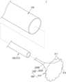
도 1은 본 발명의 일 실시예에 따른 의료용 스네어 장치를 도시한 부분사시도이다.
도 2는 본 발명의 일 실시예에 따른 의료용 스네어 장치를 도시한 분해사시도이다.
도 3은 본 발명의 일 실시예에 따른 포획부를 도시한 평면도이다.
도 4는 본 발명의 일 실시예에 따른 스네어부가 본체부의 내부에 위치한 모습을 도시한 도면이다.
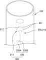
도 5는 본 발명의 일 실시예에 따른 의료용 스네어 장치의 사용 상태를 도시한 도면이다.
도 6은 본 발명의 다른 실시예에 따른 의료용 스네어 장치를 도시한 도면이다.
도 7은 본 발명의 또 다른 실시예에 따른 의료용 스네어 장치를 도시한 도면이다.1 is a partial perspective view showing a medical snare device according to an embodiment of the present invention.
2 is an exploded perspective view showing a medical snare device according to an embodiment of the present invention.
3 is a plan view illustrating a catching unit according to an embodiment of the present invention.
4 is a view showing a state in which the snare part is located inside the body part according to an embodiment of the present invention.
5 is a view showing a state of use of a medical snare device according to an embodiment of the present invention.
6 is a view showing a medical snare device according to another embodiment of the present invention.
7 is a view showing a medical snare device according to another embodiment of the present invention.
본 발명은 다양한 변환을 가할 수 있고 여러 가지 실시예를 가질 수 있는 바, 특정 실시예들을 도면에 예시하고 상세한 설명에 상세하게 설명하고자 한다. 본 발명의 효과 및 특징, 그리고 그것들을 달성하는 방법은 도면과 함께 상세하게 후술되어 있는 실시예들을 참조하면 명확해질 것이다. 그러나 본 발명은 이하에서 개시되는 실시예들에 한정되는 것이 아니라 다양한 형태로 구현될 수 있다.Since the present invention can apply various transformations and have various embodiments, specific embodiments will be illustrated in the drawings and described in detail in the detailed description. Effects and features of the present invention, and methods for achieving them will become clear with reference to the embodiments described later in detail together with the drawings. However, the present invention is not limited to the embodiments disclosed below and may be implemented in various forms.
이하, 첨부된 도면을 참조하여 본 발명의 실시예들을 상세히 설명하기로 하며, 도면을 참조하여 설명할 때 동일하거나 대응하는 구성 요소는 동일한 도면부호를 부여하고 이에 대한 중복되는 설명은 생략하기로 한다.Hereinafter, embodiments of the present invention will be described in detail with reference to the accompanying drawings, and when describing with reference to the drawings, the same or corresponding components are assigned the same reference numerals, and overlapping descriptions thereof will be omitted. .
이하의 실시예에서, 제1, 제2 등의 용어는 한정적인 의미가 아니라 하나의 구성 요소를 다른 구성 요소와 구별하는 목적으로 사용되었다.In the following embodiments, terms such as first and second are used for the purpose of distinguishing one component from another component without limiting meaning.
이하의 실시예에서, 단수의 표현은 문맥상 명백하게 다르게 뜻하지 않는 한, 복수의 표현을 포함한다.In the following examples, expressions in the singular number include plural expressions unless the context clearly dictates otherwise.
이하의 실시예에서, 포함하다 또는 가지다 등의 용어는 명세서상에 기재된 특징, 또는 구성요소가 존재함을 의미하는 것이고, 하나 이상의 다른 특징들 또는 구성요소가 부가될 가능성을 미리 배제하는 것은 아니다.In the following embodiments, terms such as include or have mean that features or components described in the specification exist, and do not preclude the possibility that one or more other features or components may be added.
이하의 실시예에서, 막, 영역, 구성 요소 등의 부분이 다른 부분 위에 또는 상에 있다고 할 때, 다른 부분의 바로 위에 있는 경우뿐만 아니라, 그 중간에 다른 막, 영역, 구성 요소 등이 개재되어 있는 경우도 포함한다.In the following embodiments, when a part such as a film, region, component, etc. is said to be on or on another part, not only when it is directly above the other part, but also when another film, region, component, etc. is interposed therebetween. Including if there is
도면에서는 설명의 편의를 위하여 구성 요소들이 그 크기가 과장 또는 축소될 수 있다. 예컨대, 도면에서 나타난 각 구성의 크기 및 두께는 설명의 편의를 위해 임의로 나타내었으므로, 본 발명이 반드시 도시된 바에 한정되지 않는다.In the drawings, the size of components may be exaggerated or reduced for convenience of explanation. For example, since the size and thickness of each component shown in the drawings are arbitrarily shown for convenience of description, the present invention is not necessarily limited to the illustrated bar.
어떤 실시예가 달리 구현 가능한 경우에 특정한 공정 순서는 설명되는 순서와 다르게 수행될 수도 있다. 예를 들어, 연속하여 설명되는 두 공정이 실질적으로 동시에 수행될 수도 있고, 설명되는 순서와 반대의 순서로 진행될 수 있다.When an embodiment is otherwise implementable, a specific process sequence may be performed differently from the described sequence. For example, two processes described in succession may be performed substantially simultaneously, or may be performed in an order reverse to the order described.
이하의 실시예에서, 막, 영역, 구성 요소 등이 연결되었다고 할 때, 막, 영역, 구성 요소들이 직접적으로 연결된 경우뿐만 아니라 막, 영역, 구성요소들 중간에 다른 막, 영역, 구성 요소들이 개재되어 간접적으로 연결된 경우도 포함한다. 예컨대, 본 명세서에서 막, 영역, 구성 요소 등이 전기적으로 연결되었다고 할 때, 막, 영역, 구성 요소 등이 직접 전기적으로 연결된 경우뿐만 아니라, 그 중간에 다른 막, 영역, 구성 요소 등이 개재되어 간접적으로 전기적 연결된 경우도 포함한다.In the following embodiments, when it is assumed that films, regions, components, etc. are connected, not only are the films, regions, and components directly connected, but also other films, regions, and components are interposed between the films, regions, and components. This includes cases where it is connected indirectly. For example, when a film, region, component, etc. is electrically connected in this specification, not only is the film, region, component, etc. directly electrically connected, but another film, region, component, etc. is interposed therebetween. Including cases of indirect electrical connection.
도 1은 본 발명의 일 실시예에 따른 의료용 스네어 장치를 도시한 부분사시도이다. 도 2는 본 발명의 일 실시예에 따른 의료용 스네어 장치를 도시한 분해사시도이다. 도 3은 본 발명의 일 실시예에 따른 포획부를 도시한 평면도이다. 도 4는 본 발명의 일 실시예에 따른 스네어부가 본체부의 내부에 위치한 모습을 도시한 도면이다. 도 5는 본 발명의 일 실시예에 따른 의료용 스네어 장치의 사용 상태를 도시한 도면이다.1 is a partial perspective view showing a medical snare device according to an embodiment of the present invention. 2 is an exploded perspective view showing a medical snare device according to an embodiment of the present invention. 3 is a plan view illustrating a catching unit according to an embodiment of the present invention. 4 is a view showing a state in which the snare part is located inside the body part according to an embodiment of the present invention. 5 is a view showing a state of use of a medical snare device according to an embodiment of the present invention.
도 1 내지 도 5를 참조하면, 본 발명의 일 실시예에 따른 의료용 스네어 장치(1)는 본체부(100), 가이드부(200), 스네어부(300)를 포함할 수 있다.Referring to FIGS. 1 to 5 , the
도 1, 도 2, 도 4, 도 5를 참조하면, 본 발명의 일 실시예에 따른 본체부(100)는 양측이 개구되고, 내부가 중공으로 형성되는 것으로 원통 형상으로 형성될 수 있다.Referring to FIGS. 1, 2, 4, and 5 , the
본 발명의 일 실시예에 따른 본체부(100)는 길이 방향 중심축을 따라 연장 형성되며, 혈관이나 위장관 내에 투입이 가능하도록 미리 설정된 단면적을 가지도록 형성될 수 있다.The
본 발명에서는 본체부(100)가 원통 형상으로 형성되나, 이에 한정하는 것은 아니고 뒤에 설명할 가이드부(200), 스네어부(300)가 본체부(100)의 내부에서 길이 방향을 따라 이동가능하게 배치되는 기술적 사상 안에서 다양한 변형실시가 가능하다.In the present invention, the
본 발명의 일 실시예에 따른 본체부(100)는 길이 방향 중심축을 기준으로 횡단면의 면적이 가이드부(200)의 길이 방향 중심축을 기준으로 횡단면의 면적보다 상대적으로 크게 형성될 수 있다.The
이로 인하여 사용자가 본체부(100)를 파지하고 제거 대상체(5)의 위치까지 본체부(100)를 이동시키고, 상기 위치에서 가이드부(200)를 본체부(100)의 내부에서 이동시키고 뒤에 설명할 스네어부(300)를 가이드부(200)의 내부에서 이동시켜 대상체(5)를 안정적으로 포획할 수 있는 효과가 있다.Due to this, the user grips the
도 1, 도 2 및 도 4, 도 5를 참조하면, 본 발명의 일 실시예에 따른 본체부(100)는 폴리퍼(polymer) 재질로 형성될 수 있고, 이로 인하여 혈관이나 위장관 내에서 유연하게 이동할 수 있는 효과가 있다.Referring to FIGS. 1, 2, 4, and 5, the
도 1, 도 2 및 도 4, 도 5를 참조하면, 본 발명의 일 실시예에 따른 본체부(100)는 직경이 5 내지 15fr로 형성될 수 있다. 5 내지 15fr은 1.67 내지 5mm를 의미한다.Referring to FIGS. 1, 2, 4, and 5 , the
본 발명의 일 실시예에 따른 본체부(100)의 길이는 10 내지 200cm의 범위에서 투입되는 혈관 또는 위장관 등을 고려하여 미리 설정되는 길이 내에서 다양하게 변형 실시가 가능하다.The length of the
도 1, 도 2, 도 4, 도 5, 도 6을 참조하면, 본 발명의 일 실시예에 따른 가이드부(200)는 본체부(100)의 내측에서 상대 이동가능한 것으로 내부가 중공으로 형성될 수 있다.Referring to FIGS. 1, 2, 4, 5, and 6, the
도 2를 참조하면, 본 발명의 일 실시예에 따른 가이드부(200)는 원통 형상으로 형성될 수 있고, 길이 방향 중심축을 기준으로 횡단면의 면적이 본체부(100)의 길이 방향 중심축을 기준으로 횡단면의 면적보다 작게 형성될 수 있다.Referring to FIG. 2 , the
이로 인하여 가이드부(200)와 본체부(100) 간 상대 이동이 가능한데, 본체부(100)가 위치 고정된 상태에서 사용자가 가이드부(200)를 이동시킬 수 있고, 가이드부(200)가 위치 고정된 상태에서 사용자가 본체부(100)를 이동시킬 수 있다.Due to this, relative movement between the
즉, 본 발명의 일 실시예에 따른 가이드부(200)와 본체부(100) 간의 상대 이동으로 인하여 혈관이나 위장관 내 이물질 또는 일시적으로 삽입하였던 기구(inferior vena cava filter, stent 등) 등의 대상체(5)가 위치하는 영역까지 이동시킨 다음에 가이드부(200)를 본체부(100)의 내부에서 토출시키고, 가이드부(200)의 내부에서 이동이 가능한 스네어부(300)를 통해 대상체(5)를 안정적으로 포획, 제거할 수 있는 효과가 있다.That is, due to the relative movement between the
본 발명의 일 실시예에 따른 가이드부(200)는 금속 또는 폴리머 재질로 형성될 수 있고, 미리 설정된 강성을 가지며 본체부(100)의 내부에서 형상이 고정된 상태를 유지할 수 있다.The
이로 인하여 가이드부(200)의 내부에서 스네어부(300)가 안정적으로 위치 고정될 수 있고, 대상체(5)의 위치까지 가이드부(200)가 이동 후 스네어부(300)로 대상체(5)를 감싸며 혈관이나 위장관 내에서 제거할 수 있는 효과가 있다.Due to this, the
도 1 내지 도 5를 참조하면, 본 발명의 일 실시예에 따른 스네어부(300)는 가이드부(200)의 내부에서 이동이 가능한 것으로, 포획부(310), 지지부(330, 330A, 330B)를 포함할 수 있다.1 to 5, the
본 발명의 일 실시예에 따른 스네어부(300)는 스틸(steel) 재질 또는 폴리머 재질로 형성될 수 있으며, 스네어부(300)의 직경은 5 내지 40mm로 형성될 수 있다.The
도 4, 도 5를 참조하면, 본 발명의 일 실시예에 따른 스네어부(300)는 본체부(100), 가이드부(200)의 내부에서 이동이 가능하고, 본체부(100), 가이드부(200)의 길이에 대응되는 길이로 연장 형성될 수 있다.4 and 5, the
도 1 내지 도 5를 참조하면, 본 발명의 일 실시예에 따른 포획부(310)는 포획홀부(312)가 형성되는 것으로, 포획홀부(312)의 내측에 대상체(5)가 위치한 뒤에 사용자가 스네어부(300)를 잡아 당김으로써 대상체(5)를 안정적으로 제거할 수 있는 효과가 있다.Referring to FIGS. 1 to 5 , the
도 3을 참조하면, 본 발명의 일 실시예에 따른 포획부(310)는 복수 개의 호(311)(arc)가 구비되고, 복수 개의 호(311)는 양단부가 다른 호(311)의 양단부와 각각 연결될 수 있다.Referring to FIG. 3, the catching
도 3을 참조하면, 복수 개의 각 호(311)의 중앙 지점을 가상의 선으로 연결하면 하나의 원(circle)이 형성될 수 있는데, 복수 개의 각 호(311)의 곡률 반경은 상기 가상의 선을 연결하여 형성되는 원의 미리 설정되는 영역에서의 곡률 반경보다 작게 형성될 수 있다.Referring to FIG. 3 , a circle may be formed by connecting the central points of the plurality of
도 3을 참조하면, 포획부(310)의 중심(C)에서 서로 다른 호(311)가 연결되는 지점인 각 호(311)의 양단부까지의 거리(d2)는 포획부(310)의 중심(C)에서 각 호(311)의 중앙 지점, 즉 가상의 선으로 연결하여 형성되는 원까지의 거리(d1)보다 상대적으로 짧게 형성될 수 있다.Referring to FIG. 3 , the distance d2 from the center C of the catching
다시 말하여, 복수 개의 호(311)가 서로 연결되는 지점에서 포획홀부(312)의 중심까지의 거리는 호(311)의 중심에서 포획홀부(312)의 중심까지의 거리보다 상대적으로 짧게 형성될 수 있다.In other words, the distance from the point where the plurality of
이로 인하여 복수 개의 호(311)가 서로 연결되는 포획부(310)는 전체로서 큰 원형 형상을 가지지만, 상대적으로 본체부(100), 가이드부(200)의 직경이 작은 경우에도 지지부(330, 330A, 330B)를 잡아당기더라도 포획부(310), 구체적으로 복수 개의 호(311)가 부분적으로 접히면서도 가능한 원형 형상을 유지할 수 있는 효과가 있다.As a result, although the catching
다시 말하여 복수 개의 호(311)가 서로 연결되는 포획부(310)로 인하여 가이드부(200)의 외부에 위치하는 포획 영역을 원형과 유사한 형상으로 유지하면서 사용자가 스네어부(300)를 잡아 당김에 따라 포획부(310)의 내경이 변경될 수 있다.In other words, the user pulls the
이로 인하여 스네어부(300), 구체적으로 포획부(310)의 내경이 감소함에 따라 포획부(310)의 내측에 혈관이나 위장관 내의 이물질 또는 일시적으로 삽입하였던 기구 등의 대상체(5)를 파지하거나 조일 수 있다.As a result, as the inner diameter of the
이에 더하여 포획 영역의 넓이를 조절할 수 있고, 단일 제원의 본체부(100), 가이드부(200)가 아니라 다양한 직경을 가지는 본체부(100), 가이드부(200)에도 적용이 가능한 효과가 있다.In addition to this, the width of the capture area can be adjusted, and there is an effect that can be applied to the
도 1, 도 2, 도 4, 도 5를 참조하면, 본 발명의 일 실시예에 따른 지지부(330, 330A, 330B)는 가이드부(200)의 내부에서 상대 이동이 가능한 것으로 포획부(310)에 연결될 수 있다. 지지부(330, 330A, 330B)는 복수 개가 구비되며 포획부(310)의 미리 설정되는 지점에 각각 연결될 수 있다.Referring to FIGS. 1, 2, 4, and 5, the
본 발명의 일 실시예에 따른 지지부(330, 330A, 330B)는 스틸 재질로 형성될 수 있고, 미리 설정되는 강도로 형성되며 강성이 확보됨에 따라 스네어부(300)를 이동시킴에 따라 지지부(330, 330A, 330B)와 연결되는 스네어부(300)를 대상체(5)의 위치까지 안정적으로 이동시킬 수 있다.The
도 1, 도 2를 참조하면, 본 발명의 일 실시예에 따른 복수 개의 지지부(330, 330A, 330B)는 포획홀부(312)의 중심을 기준으로 서로 마주보며 배치될 수 있다.Referring to FIGS. 1 and 2 , the plurality of
도 5를 참조하면, 지지부(330, 330A, 330B)가 복수 개 구비되며 포획부(310)에 각각 연결됨으로 인하여 사용자가 스네어부(300)의 각도와 위치를 조절하여 대상체(5)를 포착함에 있어 스네어부(300)를 조이는 동작에서 종축 방향으로의 이동이 없어 대상체(5)를 안정적으로 포획할 수 있고, 포착한 대상체(5)를 놓치지 않고 쉽게 제거할 수 있다.Referring to FIG. 5 , since a plurality of
도 1, 도 2, 도 4 및 도 5를 참조하면, 본 발명의 일 실시예에 따른 지지부(330, 330A, 330B)는 2개가 구비되며 포획부(310) 상에서 포획홀부(312)의 중심을 기준으로 대칭을 이루는 지점에 각각 연결되나, 이에 한정하는 것은 아니고, 스네어부(300)를 잡아당김에 있어 종축 방향으로의 이동을 방지하는 기술적 사상 안에서 3개 이상 구비되는 등 다양한 변형실시가 가능하다.Referring to FIGS. 1, 2, 4, and 5, two
상기와 같은 본 발명의 일 실시예에 따른 의료용 스네어 장치(1)의 작동원리 및 효과에 관하여 설명한다.The operating principle and effect of the
도 1 내지 도 5를 참조하면, 본 발명의 일 실시예에 따른 의료용 스네어 장치(1)는 본체부(100), 가이드부(200), 스네어부(300)를 포함할 수 있다.Referring to FIGS. 1 to 5 , the
도면에 도시하지는 않았지만, 도 5를 참조하면, 의료용 스네어 장치(1)가 혈관이나 위장관 내에 위치하는 상황을 도시한 것으로, 혈관이나 위장관의 내부에는 이물질 또는 일시적으로 삽입하였던 기구 등의 대상가 위치할 수 있다.Although not shown in the drawing, referring to FIG. 5, it shows a situation in which the
도 4를 참조하면, 사용자는 내부에 가이드부(200), 스네어부(300)가 위치한 본체부(100)를 파지하고, 본체부(100)를 대상체(5)가 위치한 혈관이나 위장관의 내부의 미리 설정되는 위치로 이동시킬 수 있다.Referring to FIG. 4 , the user grips the
도 5를 참조하면, 혈관이나 위장관의 내부에 위치하는 대상체(5)에 근접하도록 본체부(100)가 도달하게 되면, 사용자는 본체부(100)를 뒤(도 4 기준 상측에서 하측 방향)로 당겨 가이드부(200), 스네어부(300)가 본체부(100)의 외부에 노출될 수 있도록 한다.Referring to FIG. 5 , when the
가이드부(200) 및 가이드부(200)의 내부에 배치되는 스네어부(300)가 본체부(100)의 외부로 노출되게 되고, 스네어부(300), 구체적으로 복수 개의 호(311)가 서로 연결되며 포획홀부(312)를 이루며 형성되는 포획부(310)의 내측에 대상체(5)가 위치하게 된다.The
도 3을 참조하면, 복수 개의 호(311)가 서로 연결되는 지점에서 포획홀부(312)의 중심까지의 거리(d2)는 호(311)의 중심에서 포획홀부(312)의 중심까지의 거리(d1)보다 상대적으로 짧게 형성될 수 있다.3, the distance d2 from the point where the plurality of
이로 인하여 복수 개의 호(311)가 서로 연결되는 포획부(310)는 포획부(310)의 중심에서 각각의 호(311)에서 가장 먼 거리를 가지는 각 호(311)의 각 중앙 지점을 가상으로 연결하면 전체로서 큰 원형 형상을 가지고, 상대적으로 본체부(100), 가이드부(200)의 직경이 작은 경우에도 지지부(330, 330A, 330B)를 잡아당기더라도 포획부(310), 구체적으로 복수 개의 호(311)가 부분적으로 찌그러지거나 접히면서도 가능한 원형 형상을 유지할 수 있는 효과가 있다.As a result, the catching
다시 말하여 복수 개의 호(311)가 서로 연결되는 포획부(310)로 인하여 가이드부(200)의 외부에 위치하는 포획 영역을 원형과 유사한 형상으로 유지하면서 사용자가 스네어부(300)를 잡아 당김에 따라 포획부(310)의 내경이 변경될 수 있다.In other words, the user pulls the
이로 인하여 스네어부(300), 구체적으로 포획부(310)의 내경이 감소함에 따라 포획부(310)의 내측에 혈관이나 위장관 내의 이물질 또는 일시적으로 삽입하였던 기구 등의 대상체(5)를 파지하거나 조일 수 있다.As a result, as the inner diameter of the
이에 더하여 포획 영역의 넓이를 조절할 수 있어, 사용하는 혈관이나 위장관의 직경에 따라 그에 대응되는 크기를 가지는 스네어 장치가 필요하나, 본 발명의 실시예들에 따른 스네어 장치는 단일 제원의 본체부(100), 가이드부(200), 스네어부(300)로 다양한 직경의 혈관이나 위장관 내에서 적용이 가능한 효과가 있다.In addition, since the width of the capture area can be adjusted, a snare device having a size corresponding to the diameter of the blood vessel or gastrointestinal tract is required, but the snare device according to the embodiments of the present invention has a single body part (100 ), the
도 1, 도 2, 도 4, 도 5를 참조하면, 지지부(330, 330A, 330B)는 복수 개가 구비되며 포획부(310) 상에서 미리 설정되는 지점에 연결될 수 있다. 구체적으로 포획홀부(312)의 중심을 기준으로 서로 마주보며 배치되는 위치에 지지부(330, 330A, 330B)가 연결될 수 있다.Referring to FIGS. 1, 2, 4, and 5 , a plurality of
지지부(330, 330A, 330B)가 복수 개 구비되며 포획부(310)에 각각 연결됨으로 인하여 스네어부(300)를 안정적으로 이동시킬 수 있고, 종방향으로의 이동을 방지하여 안정적으로 대상체(5)의 외측에 포획부(310)가 배치될 수 있도록 하고, 쉽게 포획할 수 있도록 하는 효과가 있다.A plurality of
구체적으로 가이드부(200)의 위치가 고정된 상태에서 사용자가 스네어부(300)를 일측(도 5 기준 우측에서 좌측 방향)으로 잡아당기면, 스네어부(300), 구체적으로 포획부(310)의 미리 설정되는 영역이 가이드부(200)의 내부로 들어가게 되고, 포획부(310)가 복수 개의 호(311)가 연결되는 구조로 형성됨에 따라 가이드부(200)의 내부로 들어갈 때 접히더라도 비교적 원형 형상으로 형성될 수 있고, 포획홀부(312)의 크기가 감소되며, 대상체(5)를 파지 또는 조이거나, 대상체(5)가 걸릴 수 있도록 한다.Specifically, when the user pulls the
이후에 사용자는 가이드부(200), 스네어부(300)가 본체부(100)의 내부에 배치된 상태에서 의료용 스네어 장치(1)를 혈관이나 위장관의 내부에서 외측 방향(도 5 기준 우측에서 좌측 방향)으로 이동시켜, 이물질 또는 일시적으로 삽입하였던 기구 등의 대상체(5)를 혈관이나 위장관에서 안정적으로 제거할 수 있다.Thereafter, the user moves the
본 발명의 실시예들에 따른 의료용 스네어 장치(1)는, 지지부(330, 330A, 330B)가 복수 개 구비되며 포획부(310) 상에서 미리 설정되는 위치에 연결됨으로 인하여 포획부(310)가 이물질 또는 일시적으로 삽입하였던 기구 등 대상체(5)의 외측에 안정적으로 위치시킬 수 있고, 대상체(5)를 정확하게 포착할 수 있는 효과가 있다.In the
또한, 포획부(310)가 복수 개의 호(311)가 연결되는 구조로 형성됨으로 인하여 상대적으로 직경이 작은 본체부(100) 또는 가이드부(200)의 내부에서도 포획부(310)의 크기를 감소시키는 등 조절할 수 있고, 전체 포획부(310)의 크기가 감소된다 하더라도, 복수 개의 호(311)로 인하여 원형 형상을 유지할 수 있어 대상체(5) 포획에 필요한 형상을 구현할 수 있다.In addition, since the catching
이하, 본 발명의 다른 실시예에 따른 의료용 스네어 장치의 구성, 작동원리 및 효과에 관하여 설명한다. 도 6은 본 발명의 다른 실시예에 따른 의료용 스네어 장치를 도시한 도면이다.Hereinafter, the configuration, operating principle and effect of a medical snare device according to another embodiment of the present invention will be described. 6 is a view showing a medical snare device according to another embodiment of the present invention.
도 6을 참조하면, 본 발명의 다른 실시예에 따른 의료용 스네어 장치(1)는 본체부, 가이드부(200), 스네어부(300)를 포함할 수 있다.Referring to FIG. 6 , a
도 6을 참조하면, 본 발명의 다른 실시예에 따른 가이드부(200)는 가이드본체(210, 210A, 210B)를 포함할 수 있다. 구체적으로 가이드부(200)는 복수 개의 지지부(330, 330A, 330B)에 대응되도록 복수 개의 가이드본체(210, 210A, 210B)를 포함할 수 있다.Referring to Figure 6, the
도 6을 참조하면, 복수 개의 가이드본체(210, 210A, 210B)의 내부에는 각각 복수 개의 지지부(330, 330A, 330B)가 배치되며, 가이드본체(210, 210A, 210B)가 복수 개 형성됨에 따라 지지부(330, 330A, 330B)의 이동 경로를 안정적으로 가이드할 수 있는 효과가 있다.Referring to FIG. 6, a plurality of
도 6을 참조하면, 본 발명의 다른 실시예에 따른 가이드부(200)는 단일 구간으로 형성될 수 있고, 소정 구간에서 복수 개의 가이드본체(210, 210A, 210B)가 형성되며, 복수 개의 가이드본체(210, 210A, 210B)의 내부에 복수 개의 지지부(330, 330A, 330B)가 각각 배치될 수 있다.Referring to FIG. 6, the
그러나 이에 한정하는 것은 아니고 가이드부(200)가 복수 개 구비되며, 길이 방향을 따라 복수 개의 지지부(330, 330A, 330B)가 각각의 가이드부(200)의 내측에서 이동될 수 있는 등 다양한 변형실시가 가능하다.However, it is not limited to this, and a plurality of
도 6을 참조하면, 지지부(330, 330A, 330B)는 소정 구간까지는 일체로 형성되고, 소정 구간을 지나서는 복수 개로 분리되며 포획부(310) 상의 미리 설정되는 지점에 각각 연결될 수 있다. 그러나 이에 한정하는 것은 아니고, 도 7에 도시된 바와 같이 복수 개의 지지부(330A, 330B)가 길이 방향을 따라 일체로 형성되는 구간 없이 계속 독립적으로 형성되는 등 다양한 변형실시가 가능하다.Referring to FIG. 6 , the
본 발명의 다른 실시예에 따른 의료용 스네어 장치는, 가이드부(200)의 미리 설정되는 구간이 복수 개의 지지부(330, 330A, 330B)에 대응되도록 복수 개의 가이드본체(210A, 210B)를 포함하는 것을 제외하고는 본 발명의 일 실시예에 따른 의료용 스네어 장치(1)와 구성 및 작동원리 및 효과가 동일하므로 이와 중복되는 범위에서 자세한 설명은 생략한다.A medical snare device according to another embodiment of the present invention includes a plurality of
본 발명에서 설명하는 특정 실행들은 일 실시예들로서, 어떠한 방법으로도 본 발명의 범위를 한정하는 것은 아니다. 명세서의 간결함을 위하여, 종래 전자적인 구성들, 제어 시스템들, 소프트웨어, 상기 시스템들의 다른 기능적인 측면들의 기재는 생략될 수 있다. 또한, 도면에 도시된 구성 요소들 간의 선들의 연결 또는 연결 부재들은 기능적인 연결 및/또는 물리적 또는 회로적 연결들을 예시적으로 나타낸 것으로서, 실제 장치에서는 대체 가능하거나 추가의 다양한 기능적인 연결, 물리적인 연결, 또는 회로 연결들로서 나타내어질 수 있다. 또한, "필수적인", "중요하게" 등과 같이 구체적인 언급이 없다면 본 발명의 적용을 위하여 반드시 필요한 구성 요소가 아닐 수 있다.Specific implementations described herein are examples and do not limit the scope of the present invention in any way. For brevity of the specification, description of conventional electronic components, control systems, software, and other functional aspects of the systems may be omitted. In addition, the connection of lines or connecting members between the components shown in the drawings are examples of functional connections and / or physical or circuit connections, which can be replaced in actual devices or additional various functional connections, physical connection, or circuit connections. In addition, if there is no specific reference such as "essential" or "important", it may not necessarily be a component necessary for the application of the present invention.
따라서, 본 발명의 사상은 상기 설명된 실시예에 국한되어 정해져서는 아니 되며, 후술하는 특허청구범위뿐만 아니라 이 특허청구범위와 균등한 또는 이로부터 등가적으로 변경된 모든 범위는 본 발명의 사상의 범주에 속한다고 할 것이다.Therefore, the spirit of the present invention should not be limited to the above-described embodiments and should not be determined, and all scopes equivalent to or equivalently changed from the claims as well as the claims described below are within the scope of the spirit of the present invention. will be said to belong to
1: 의료용 스네어 장치5: 대상체
100: 본체부200: 가이드부
210, 210A, 210B: 가이드본체
300: 스네어부310: 포획부
311: 호(arc)312: 포획홀부
330, 330A, 330B: 지지부1: Medical snare device 5: Object
100: body part 200: guide part
210, 210A, 210B: guide body
300: snare part 310: catch part
311: arc 312: catch hole
330, 330A, 330B: support
Claims (7)
Translated fromKorean상기 본체부의 내측에서 상대 이동가능하며, 내부가 중공인 가이드부; 및
포획홀부가 형성되는 포획부와; 상기 가이드부의 내부에서 상대 이동가능하며, 상기 포획부에 연결되는 지지부;가 구비되는 스네어부;를 포함하고,
상기 지지부는 복수 개가 구비되며 상기 포획부의 미리 설정되는 지점에 각각 연결되고,
상기 포획부는 연속하여 배치되는 복수 개의 호를 포함하고,
상기 포획홀부의 중심에서 상기 복수 개의 호의 양단부까지의 거리는 상기 포획홀부의 중심에서 상기 복수 개의 호의 중심까지의 거리보다 짧은 것을 특징으로 하는 의료용 스네어 장치.a main body portion that is open on both sides and has a hollow interior;
a guide part that is relatively movable inside the main body part and has a hollow inside; and
a catching part in which a catching hole is formed; A snare part provided with a support part that is relatively movable inside the guide part and connected to the catching part,
The support part is provided with a plurality of pieces and is connected to a pre-set point of the catching part, respectively,
The catching unit includes a plurality of arcs arranged in succession,
The medical snare device of claim 1 , wherein a distance from the center of the catching hole to both ends of the plurality of arcs is shorter than a distance from the center of the catching hole to the center of the plurality of arcs.
복수 개의 상기 지지부는 상기 포획홀부의 중심을 기준으로 서로 마주보며 배치되는 것을 특징으로 하는 의료용 스네어 장치.According to claim 1,
The medical snare device, characterized in that the plurality of support parts are disposed facing each other based on the center of the catching hole.
복수 개의 상기 지지부는 미리 설정되는 구간에서 일체로 형성되는 것을 특징으로 하는 의료용 스네어 장치.According to claim 1,
The medical snare device, characterized in that the plurality of support parts are integrally formed in a preset section.
상기 가이드부는 복수 개의 지지부의 이동 경로를 각각 제공하는 복수 개의 가이드본체;를 포함하는 것을 특징으로 하는 의료용 스네어 장치.According to claim 1,
The medical snare device comprising a plurality of guide bodies providing movement paths of the plurality of support units, respectively.
복수 개의 상기 가이드본체는 미리 설정되는 구간에서 일체로 형성되는 것을 특징으로 하는 의료용 스네어 장치.According to claim 4,
A medical snare device, characterized in that the plurality of guide bodies are integrally formed in a preset section.
상기 본체부는 폴리머(polymer) 재질로 형성되는 것을 특징으로 하는 의료용 스네어 장치.According to claim 1,
The medical snare device, characterized in that the main body is formed of a polymer material.
상기 지지부는 금속 또는 폴리머 재질로 형성되는 것을 특징으로 하는 의료용 스네어 장치.
According to claim 1,
The medical snare device, characterized in that the support portion is formed of a metal or polymer material.
Priority Applications (4)
| Application Number | Priority Date | Filing Date | Title |
|---|---|---|---|
| KR1020200141566AKR102528715B1 (en) | 2020-10-28 | 2020-10-28 | Medical snare apparatus |
| PCT/KR2021/006941WO2022092471A1 (en) | 2020-10-28 | 2021-06-03 | Medical snare device |
| EP21886472.6AEP4238515A4 (en) | 2020-10-28 | 2021-06-03 | Medical snare device |
| US18/250,272US20230389910A1 (en) | 2020-10-28 | 2021-06-03 | Medical snare device |
Applications Claiming Priority (1)
| Application Number | Priority Date | Filing Date | Title |
|---|---|---|---|
| KR1020200141566AKR102528715B1 (en) | 2020-10-28 | 2020-10-28 | Medical snare apparatus |
Publications (2)
| Publication Number | Publication Date |
|---|---|
| KR20220056725A KR20220056725A (en) | 2022-05-06 |
| KR102528715B1true KR102528715B1 (en) | 2023-05-04 |
Family
ID=81384172
Family Applications (1)
| Application Number | Title | Priority Date | Filing Date |
|---|---|---|---|
| KR1020200141566AActiveKR102528715B1 (en) | 2020-10-28 | 2020-10-28 | Medical snare apparatus |
Country Status (4)
| Country | Link |
|---|---|
| US (1) | US20230389910A1 (en) |
| EP (1) | EP4238515A4 (en) |
| KR (1) | KR102528715B1 (en) |
| WO (1) | WO2022092471A1 (en) |
Citations (6)
| Publication number | Priority date | Publication date | Assignee | Title |
|---|---|---|---|---|
| US20070027456A1 (en)* | 2005-08-01 | 2007-02-01 | Ension, Inc. | Integrated medical apparatus for non-traumatic grasping, manipulating and closure of tissue |
| US20070239141A1 (en) | 2000-11-03 | 2007-10-11 | William A. Cook Australia Pty Ltd. | Medical grasping device |
| US20090112244A1 (en)* | 2007-10-25 | 2009-04-30 | Franz Freudenthal | Snare mechanism for surgical retrieval |
| EP1909672B1 (en) | 2005-08-04 | 2011-11-02 | C.R.Bard, Inc. | Implant introducer |
| US20140276910A1 (en) | 2013-03-14 | 2014-09-18 | Boston Scientific Scimed, Inc. | Retrieval device and related methods of use |
| JP2017500156A (en) | 2013-12-24 | 2017-01-05 | ボストン サイエンティフィック サイムド,インコーポレイテッドBoston Scientific Scimed,Inc. | Medical recovery apparatus and method |
Family Cites Families (11)
| Publication number | Priority date | Publication date | Assignee | Title |
|---|---|---|---|---|
| US4471777A (en)* | 1983-03-30 | 1984-09-18 | Mccorkle Jr Charles E | Endocardial lead extraction apparatus and method |
| ATE131370T1 (en)* | 1989-08-16 | 1995-12-15 | Raychem Corp | ARRANGEMENT FOR GRABING OR CUTTING AN OBJECT |
| US5535759A (en)* | 1994-11-02 | 1996-07-16 | Wilk; Peter J. | Endoscopic method of cleaning and operating on a site within a patient |
| KR101298690B1 (en) | 2011-01-25 | 2013-08-21 | 신경민 | Medical Snare |
| US9445828B2 (en)* | 2012-07-05 | 2016-09-20 | Cognition Medical Corp. | Methods, devices, and systems for postconditioning with clot removal |
| CN105451669A (en)* | 2013-06-20 | 2016-03-30 | 波士顿科学国际有限公司 | Supported retrieval device and related methods of use |
| DE102014205366B4 (en)* | 2014-03-21 | 2019-03-28 | Coloplast A/S | Catch wire instrument with catch wire structure made of tubular piece |
| WO2015168155A1 (en)* | 2014-04-29 | 2015-11-05 | Cardiac Pacemakers, Inc. | Leadless cardiac pacemaker with retrieval features |
| KR20190012946A (en)* | 2017-07-31 | 2019-02-11 | 주식회사 지에스엠티 | Catheter for removing calculus |
| JP7645074B2 (en)* | 2018-03-15 | 2025-03-13 | シー・アール・バード・インコーポレーテッド | Anatomical Extraction Device |
| US11006973B2 (en)* | 2019-01-17 | 2021-05-18 | Olympus Corporation | Method for constricting tissue |
- 2020
- 2020-10-28KRKR1020200141566Apatent/KR102528715B1/enactiveActive
- 2021
- 2021-06-03EPEP21886472.6Apatent/EP4238515A4/enactivePending
- 2021-06-03WOPCT/KR2021/006941patent/WO2022092471A1/ennot_activeCeased
- 2021-06-03USUS18/250,272patent/US20230389910A1/enactivePending
Patent Citations (6)
| Publication number | Priority date | Publication date | Assignee | Title |
|---|---|---|---|---|
| US20070239141A1 (en) | 2000-11-03 | 2007-10-11 | William A. Cook Australia Pty Ltd. | Medical grasping device |
| US20070027456A1 (en)* | 2005-08-01 | 2007-02-01 | Ension, Inc. | Integrated medical apparatus for non-traumatic grasping, manipulating and closure of tissue |
| EP1909672B1 (en) | 2005-08-04 | 2011-11-02 | C.R.Bard, Inc. | Implant introducer |
| US20090112244A1 (en)* | 2007-10-25 | 2009-04-30 | Franz Freudenthal | Snare mechanism for surgical retrieval |
| US20140276910A1 (en) | 2013-03-14 | 2014-09-18 | Boston Scientific Scimed, Inc. | Retrieval device and related methods of use |
| JP2017500156A (en) | 2013-12-24 | 2017-01-05 | ボストン サイエンティフィック サイムド,インコーポレイテッドBoston Scientific Scimed,Inc. | Medical recovery apparatus and method |
Also Published As
| Publication number | Publication date |
|---|---|
| KR20220056725A (en) | 2022-05-06 |
| WO2022092471A1 (en) | 2022-05-05 |
| US20230389910A1 (en) | 2023-12-07 |
| EP4238515A1 (en) | 2023-09-06 |
| EP4238515A4 (en) | 2024-08-21 |
Similar Documents
| Publication | Publication Date | Title |
|---|---|---|
| US8911354B2 (en) | Resin tube and endoscope | |
| US20170135562A1 (en) | Endoscope stabilization system | |
| US10582938B2 (en) | Medical retrieval devices and related methods of use | |
| US11801362B2 (en) | Surgical cannulas and related methods | |
| EP1982660A1 (en) | Treatment endoscope | |
| US20110124960A1 (en) | Devices for introducing multiple instruments and methods of use | |
| US20110106077A1 (en) | Treatment instrument | |
| US9089264B2 (en) | Medical coil, method of manufacturing the same, and medical instrument | |
| US9795401B2 (en) | Medical retrieval devices and related methods of use | |
| KR102528715B1 (en) | Medical snare apparatus | |
| US20160158495A1 (en) | Catheter and manufacturing method thereof | |
| EP4472482A1 (en) | Systems and method for trans-luminal introduction of a medical device | |
| US7217246B1 (en) | Method and apparatus for retaining a fixation pin to a cannula | |
| US10349962B2 (en) | Endoscope treatment tool | |
| KR102360136B1 (en) | Medical snare apparatus | |
| US7404817B2 (en) | High-frequency incision device | |
| EP4091527A1 (en) | Imaging catheter, tip, tube body, and medical apparatus | |
| US11457938B2 (en) | Foreign substance removing device and foreign substance collecting system | |
| US20130090631A1 (en) | Medical device delivery apparatus | |
| KR20220134064A (en) | Device for removing blood clots in the form of a 3D noose | |
| WO2018122907A1 (en) | Basket-type treatment tool | |
| JPH11299728A (en) | Treatment tool standing device of endoscope | |
| US20240225673A1 (en) | Medical devices and related methods thereof | |
| JP2020146387A (en) | Medical device | |
| KR20160056726A (en) | Endoscope tube |
Legal Events
| Date | Code | Title | Description |
|---|---|---|---|
| PA0109 | Patent application | St.27 status event code:A-0-1-A10-A12-nap-PA0109 | |
| PA0201 | Request for examination | St.27 status event code:A-1-2-D10-D11-exm-PA0201 | |
| D13-X000 | Search requested | St.27 status event code:A-1-2-D10-D13-srh-X000 | |
| D14-X000 | Search report completed | St.27 status event code:A-1-2-D10-D14-srh-X000 | |
| PG1501 | Laying open of application | St.27 status event code:A-1-1-Q10-Q12-nap-PG1501 | |
| E902 | Notification of reason for refusal | ||
| PE0902 | Notice of grounds for rejection | St.27 status event code:A-1-2-D10-D21-exm-PE0902 | |
| P11-X000 | Amendment of application requested | St.27 status event code:A-2-2-P10-P11-nap-X000 | |
| P13-X000 | Application amended | St.27 status event code:A-2-2-P10-P13-nap-X000 | |
| E701 | Decision to grant or registration of patent right | ||
| PE0701 | Decision of registration | St.27 status event code:A-1-2-D10-D22-exm-PE0701 | |
| PR0701 | Registration of establishment | St.27 status event code:A-2-4-F10-F11-exm-PR0701 | |
| PR1002 | Payment of registration fee | St.27 status event code:A-2-2-U10-U11-oth-PR1002 Fee payment year number:1 | |
| PG1601 | Publication of registration | St.27 status event code:A-4-4-Q10-Q13-nap-PG1601 |