KR102528500B1 - Display apparatus - Google Patents
Display apparatusDownload PDFInfo
- Publication number
- KR102528500B1 KR102528500B1KR1020180083825AKR20180083825AKR102528500B1KR 102528500 B1KR102528500 B1KR 102528500B1KR 1020180083825 AKR1020180083825 AKR 1020180083825AKR 20180083825 AKR20180083825 AKR 20180083825AKR 102528500 B1KR102528500 B1KR 102528500B1
- Authority
- KR
- South Korea
- Prior art keywords
- data
- line
- disposed
- display area
- display device
- Prior art date
- Legal status (The legal status is an assumption and is not a legal conclusion. Google has not performed a legal analysis and makes no representation as to the accuracy of the status listed.)
- Active
Links
Images


Classifications
- H—ELECTRICITY
- H10—SEMICONDUCTOR DEVICES; ELECTRIC SOLID-STATE DEVICES NOT OTHERWISE PROVIDED FOR
- H10K—ORGANIC ELECTRIC SOLID-STATE DEVICES
- H10K50/00—Organic light-emitting devices
- H10K50/80—Constructional details
- H—ELECTRICITY
- H10—SEMICONDUCTOR DEVICES; ELECTRIC SOLID-STATE DEVICES NOT OTHERWISE PROVIDED FOR
- H10K—ORGANIC ELECTRIC SOLID-STATE DEVICES
- H10K59/00—Integrated devices, or assemblies of multiple devices, comprising at least one organic light-emitting element covered by group H10K50/00
- H10K59/10—OLED displays
- H10K59/12—Active-matrix OLED [AMOLED] displays
- H10K59/131—Interconnections, e.g. wiring lines or terminals
- H10K59/1315—Interconnections, e.g. wiring lines or terminals comprising structures specially adapted for lowering the resistance
- H—ELECTRICITY
- H10—SEMICONDUCTOR DEVICES; ELECTRIC SOLID-STATE DEVICES NOT OTHERWISE PROVIDED FOR
- H10K—ORGANIC ELECTRIC SOLID-STATE DEVICES
- H10K59/00—Integrated devices, or assemblies of multiple devices, comprising at least one organic light-emitting element covered by group H10K50/00
- H10K59/10—OLED displays
- H10K59/12—Active-matrix OLED [AMOLED] displays
- H10K59/131—Interconnections, e.g. wiring lines or terminals
- H—ELECTRICITY
- H10—SEMICONDUCTOR DEVICES; ELECTRIC SOLID-STATE DEVICES NOT OTHERWISE PROVIDED FOR
- H10K—ORGANIC ELECTRIC SOLID-STATE DEVICES
- H10K59/00—Integrated devices, or assemblies of multiple devices, comprising at least one organic light-emitting element covered by group H10K50/00
- H10K59/10—OLED displays
- H10K59/12—Active-matrix OLED [AMOLED] displays
- H10K59/121—Active-matrix OLED [AMOLED] displays characterised by the geometry or disposition of pixel elements
- H10K59/1213—Active-matrix OLED [AMOLED] displays characterised by the geometry or disposition of pixel elements the pixel elements being TFTs
- H—ELECTRICITY
- H10—SEMICONDUCTOR DEVICES; ELECTRIC SOLID-STATE DEVICES NOT OTHERWISE PROVIDED FOR
- H10K—ORGANIC ELECTRIC SOLID-STATE DEVICES
- H10K59/00—Integrated devices, or assemblies of multiple devices, comprising at least one organic light-emitting element covered by group H10K50/00
- H10K59/10—OLED displays
- H10K59/12—Active-matrix OLED [AMOLED] displays
- H10K59/126—Shielding, e.g. light-blocking means over the TFTs
- H—ELECTRICITY
- H10—SEMICONDUCTOR DEVICES; ELECTRIC SOLID-STATE DEVICES NOT OTHERWISE PROVIDED FOR
- H10K—ORGANIC ELECTRIC SOLID-STATE DEVICES
- H10K77/00—Constructional details of devices covered by this subclass and not covered by groups H10K10/80, H10K30/80, H10K50/80 or H10K59/80
- H10K77/10—Substrates, e.g. flexible substrates
- H10K77/111—Flexible substrates
- H—ELECTRICITY
- H10—SEMICONDUCTOR DEVICES; ELECTRIC SOLID-STATE DEVICES NOT OTHERWISE PROVIDED FOR
- H10K—ORGANIC ELECTRIC SOLID-STATE DEVICES
- H10K2102/00—Constructional details relating to the organic devices covered by this subclass
- H10K2102/301—Details of OLEDs
- H10K2102/302—Details of OLEDs of OLED structures
- H10K2102/3023—Direction of light emission
- H—ELECTRICITY
- H10—SEMICONDUCTOR DEVICES; ELECTRIC SOLID-STATE DEVICES NOT OTHERWISE PROVIDED FOR
- H10K—ORGANIC ELECTRIC SOLID-STATE DEVICES
- H10K2102/00—Constructional details relating to the organic devices covered by this subclass
- H10K2102/301—Details of OLEDs
- H10K2102/311—Flexible OLED
- Y—GENERAL TAGGING OF NEW TECHNOLOGICAL DEVELOPMENTS; GENERAL TAGGING OF CROSS-SECTIONAL TECHNOLOGIES SPANNING OVER SEVERAL SECTIONS OF THE IPC; TECHNICAL SUBJECTS COVERED BY FORMER USPC CROSS-REFERENCE ART COLLECTIONS [XRACs] AND DIGESTS
- Y02—TECHNOLOGIES OR APPLICATIONS FOR MITIGATION OR ADAPTATION AGAINST CLIMATE CHANGE
- Y02E—REDUCTION OF GREENHOUSE GAS [GHG] EMISSIONS, RELATED TO ENERGY GENERATION, TRANSMISSION OR DISTRIBUTION
- Y02E10/00—Energy generation through renewable energy sources
- Y02E10/50—Photovoltaic [PV] energy
- Y02E10/549—Organic PV cells
Landscapes
- Engineering & Computer Science (AREA)
- Microelectronics & Electronic Packaging (AREA)
- Physics & Mathematics (AREA)
- Geometry (AREA)
- Devices For Indicating Variable Information By Combining Individual Elements (AREA)
- Electroluminescent Light Sources (AREA)
- Optics & Photonics (AREA)
Abstract
Translated fromKorean
Description
Translated fromKorean본 발명은 표시 장치에 관한 것으로, 보다 상세하게는 비표시 영역인 주변 영역이 감소된 표시 장치에 관한 것이다.The present invention relates to a display device, and more particularly, to a display device in which a peripheral area, which is a non-display area, is reduced.
최근 들어, 기술의 발전에 힘입어 소형, 경량화 되면서 성능은 더욱 뛰어난 디스플레이 제품들이 생산되고 있다. 지금까지 디스플레이 장치에는 기존 브라운관 텔레비전(cathode ray tube: CRT)이 성능이나 가격 면에서 많은 장점을 가지고 널리 사용되었으나, 소형화 또는 휴대성의 측면에서 CRT의 단점을 극복하고, 소형화, 경량화 및 저전력 소비 등의 장점을 갖는 표시 장치, 예를 들면 플라즈마 표시 장치, 액정 표시 장치 및 유기 발광 표시 장치 등이 주목을 받고 있다.In recent years, thanks to the development of technology, smaller and lighter display products with better performance are being produced. Conventional cathode ray tube (CRT) has been widely used as a display device with many advantages in terms of performance and price. A display device having advantages, such as a plasma display device, a liquid crystal display device, and an organic light emitting display device, is attracting attention.
상기 표시 장치는 영상이 표시 되는 표시 영역과 상기 표시 영역 주변의 비표시 영역인 주변 영역을 포함한다. 여기서, 상기 주변 영역의 폭을 줄이기 위한 노력이 있어서 왔다.The display device includes a display area where an image is displayed and a peripheral area that is a non-display area around the display area. Here, efforts have been made to reduce the width of the peripheral region.
이에 본 발명의 기술적 과제는 이러한 점에서 착안된 것으로, 본 발명의 목적은 비표시 영역인 주변 영역이 감소한 표시 장치를 제공하는 것이다.Therefore, the technical problem of the present invention has been focused on this point, and an object of the present invention is to provide a display device in which a peripheral area, which is a non-display area, is reduced.
상기한 본 발명의 목적을 실현하기 위한 일 실시예에 따른 표시 장치는 영상이 표시 되는 표시 영역 및 비표시 영역인 주변 영역을 포함한다. 상기 표시 장치는 베이스 기판, 상기 베이스 기판 상에 상기 표시 영역에 배치되는 제1 데이터 라인, 상기 베이스 기판 상에 적어도 일부가 상기 표시 영역에 배치되고, 연결 콘택홀을 통해 상기 제1 데이터 라인과 전기적으로 연결되는 제1 연결 라인, 상기 주변 영역에 배치되는 데이터 패드, 및 상기 데이터 패드와 상기 표시 영역 사이의 상기 주변 영역에 배치되어, 상기 제1 연결 라인 및 상기 데이터 패드와 전기적으로 연결되는 제1 데이터 스파이더 라인을 포함한다.A display device according to an embodiment for realizing the object of the present invention described above includes a display area where an image is displayed and a peripheral area which is a non-display area. The display device includes a base substrate, a first data line disposed in the display area on the base substrate, at least a portion of the base substrate disposed in the display area, and electrically connected to the first data line through a connection contact hole. A first connection line connected to , a data pad disposed in the peripheral area, and a first connection line disposed in the peripheral area between the data pad and the display area and electrically connected to the first connection line and the data pad. Include the data spider line.
본 발명의 일 실시예에 있어서, 상기 베이스 기판은 가요성 기판일 수 있다. 상기 표시 장치는 상기 데이터 패드부와 상기 표시 영역 사이에 배치되어 상기 표시 영역의 가장자리와 평행한 제1 방향으로 연장되고, 벤딩 영역을 더 포함할 수 있다. 상기 제1 데이터 스파이더 라인은 상기 벤딩 영역과 상기 표시 영역 사이의 상기 주변 영역에 배치되고, 상기 제1 방향에 수직한 제2 방향으로 일직선으로 연장될 수 있다.In one embodiment of the present invention, the base substrate may be a flexible substrate. The display device may be disposed between the data pad part and the display area, extend in a first direction parallel to an edge of the display area, and may further include a bending area. The first data spider line may be disposed in the peripheral area between the bending area and the display area and extend in a straight line in a second direction perpendicular to the first direction.
본 발명의 일 실시예에 있어서, 상기 벤딩 영역의 상기 제1 방향으로의 길이는 상기 표시 영역의 상기 제1 방향으로의 길이 보다 작을 수 있다.In one embodiment of the present invention, a length of the bending area in the first direction may be smaller than a length of the display area in the first direction.
본 발명의 일 실시예에 있어서, 상기 표시 장치는 상기 베이스 기판 상에 상기 표시 영역에 배치되고 상기 제1 데이터 라인과 평행하게 연장되는 복수의 데이터 라인들, 및 상기 데이터 패드부와 상기 표시 영역 사이의 상기 주변 영역에 배치되어, 각각의 상기 복수의 데이터 라인들과 전기적으로 연결되고, 상기 제1 데이터 스파이더 라인과 평행하게 연장되는 복수의 데이터 스파이더 라인을 더 포함할 수 있다. 상기 제1 데이터 스파이더 라인 및 상기 복수의 데이터 스파이더 라인들은 모두 상기 제2 방향으로 연장될 수 있다.In one embodiment of the present invention, the display device includes a plurality of data lines disposed in the display area on the base substrate and extending in parallel with the first data line, and between the data pad part and the display area. The data spider line may further include a plurality of data spider lines disposed in the peripheral area of , electrically connected to each of the plurality of data lines, and extending in parallel with the first data spider line. Both the first data spider line and the plurality of data spider lines may extend in the second direction.
본 발명의 일 실시예에 있어서, 상기 연결 콘택홀은 상기 주변 영역에 배치될 수 있다.In one embodiment of the present invention, the connection contact hole may be disposed in the peripheral area.
본 발명의 일 실시예에 있어서, 상기 제1 데이터 라인은 제1 방향과 수직한 제2 방향으로 연장될 수 있다. 상기 제1 연결 라인은 상기 제2 방향으로 연장되는 제1 부분, 상기 제1 부분과 연결되고 상기 제1 방향으로 연장되는 제2 부분 및 상기 제1 부분과 평행한 제3 부분을 포함할 수 있다.In one embodiment of the present invention, the first data line may extend in a second direction perpendicular to the first direction. The first connection line may include a first portion extending in the second direction, a second portion connected to the first portion and extending in the first direction, and a third portion parallel to the first portion. .
본 발명의 일 실시예에 있어서, 상기 연결 콘택홀은 상기 표시 영역 내에 배치될 수 있다.In one embodiment of the present invention, the connection contact hole may be disposed in the display area.
본 발명의 일 실시예에 있어서, 상기 표시 장치는 상기 베이스 기판 상에 상기 표시 영역에 배치되고 상기 제1 데이터 라인과 인접하여 배치되는 제2 데이터 라인을 더 포함할 수 있다. 상기 제1 및 제2 데이터 라인은 상기 주변 영역에서 서로 연결되고, 상기 제1 연결라인과 전기적으로 연결될 수 있다.In one embodiment of the present invention, the display device may further include a second data line disposed in the display area on the base substrate and disposed adjacent to the first data line. The first and second data lines may be connected to each other in the peripheral area and electrically connected to the first connection line.
본 발명의 일 실시예에 있어서, 상기 표시 장치는 상기 제1 데이터 라인과 평행하고, 상기 표시 영역의 가장자리와 평행한 제1 방향을 따라 순차적으로 배열되는 제(n-1)번째 데이터 라인, 제(n) 번째 데이터 라인 및 제(n+1) 번째 데이터 라인을 더 포함할 수 있다. 상기 데이터 패드에는 상기 제1 방향을 따라, 상기 제(n) 번째 데이터 라인과 전기적으로 연결되는 제(n) 패드, 상기 제(n-1) 번째 데이터 라인과 전기적으로 연결되는 제(n-1) 패드, 상기 제(n+1) 번째 데이터 라인과 전기적으로 연결되는 제(n+1) 패드, 및 상기 제1 데이터 라인과 전기적으로 연결되는 제n 패드가 배치될 수 있다.In one embodiment of the present invention, the display device includes a (n-1)th data line sequentially arranged along a first direction parallel to the first data line and parallel to an edge of the display area; The (n)th data line and the (n+1)th data line may be further included. The data pad includes the (n)th pad electrically connected to the (n)th data line and the (n−1th) electrically connected to the (n−1)th data line along the first direction. ) pad, the (n+1)th pad electrically connected to the (n+1)th data line, and the nth pad electrically connected to the first data line.
본 발명의 일 실시예에 있어서, 상기 표시 장치는 상기 베이스 기판 상에 적어도 일부가 상기 표시 영역에 배치되고, 연결 콘택홀을 통해 상기 제(n-1)번째 데이터 라인과 전기적으로 연결되는 제(n-1)번째 연결 라인, 상기 데이터 패드부와 상기 표시 영역 사이의 상기 주변 영역에 배치되어, 상기 제(n-1)번째 연결 라인 및 상기 데이터 패드와 전기적으로 연결되는 제(n-1)번째 데이터 스파이더 라인, 상기 데이터 패드부와 상기 표시 영역 사이의 상기 주변 영역에 배치되어, 상기 제(n)번째 데이터 라인 및 상기 데이터 패드와 전기적으로 연결되는 제(n)번째 데이터 스파이더 라인, 및 상기 데이터 패드부와 상기 표시 영역 사이의 상기 주변 영역에 배치되어, 상기 제(n+1)번째 데이터 라인 및 상기 데이터 패드와 전기적으로 연결되는 제(n+1)번째 데이터 스파이더 라인을 더 포함할 수 있다.In one embodiment of the present invention, in the display device, at least a portion of the display device is disposed in the display area on the base substrate and electrically connected to the (n-1)th data line through a connection contact hole. An n-1)th connection line, disposed in the peripheral area between the data pad part and the display area, and electrically connected to the (n-1)th connection line and the data pad (n-1) a th data spider line, a (n) th data spider line disposed in the peripheral area between the data pad unit and the display area and electrically connected to the (n) th data line and the data pad; and The method may further include an (n+1)th data spider line disposed in the peripheral area between the data pad unit and the display area and electrically connected to the (n+1)th data line and the data pad. there is.
본 발명의 일 실시예에 있어서, 상기 주변 영역은 상기 표시 영역의 좌측에 인접하는 좌측 주변 영역, 상기 표시 영역의 우측에 인접하는 우측 주변영역, 상기 표시 영역의 상측에 인접하는 상측 주변 영역 및 상기 표시 영역의 하측에 인접하는 하측 주변 영역을 포함할 수 있다. 상기 데이터 패드부는 하측 주변 영역에 배치될 수 있다.In one embodiment of the present invention, the peripheral area is a left peripheral area adjacent to the left side of the display area, a right peripheral area adjacent to the right side of the display area, an upper peripheral area adjacent to the upper side of the display area, and the A lower peripheral area adjacent to a lower side of the display area may be included. The data pad unit may be disposed in a lower peripheral area.
본 발명의 일 실시예에 있어서, 상기 표시 장치는 상기 제1 데이터 라인과 전기적으로 연결되는 박막 트랜지스터, 상기 박막 트랜지스터와 전기적으로 연결되는 제1 전극, 상기 제1 전극 상에 배치되는 제2 전극, 및 상기 제1 전극 및 상기 제2 전극 사이에 배치되는 발광층을 더 포함할 수 있다.In one embodiment of the present invention, the display device includes a thin film transistor electrically connected to the first data line, a first electrode electrically connected to the thin film transistor, a second electrode disposed on the first electrode, and a light emitting layer disposed between the first electrode and the second electrode.
본 발명의 일 실시예에 있어서, 상기 표시 장치는 상기 제1 연결 라인과 중첩하게 배치되는 쉴딩 전극을 더 포함할 수 있다. 상기 쉴딩 전극에는 제1 전원(ELVDD) 또는 제2 전원(ELVSS)이 인가될 수 있다.In one embodiment of the present invention, the display device may further include a shielding electrode disposed to overlap the first connection line. A first power source ELVDD or a second power source ELVSS may be applied to the shielding electrode.
본 발명의 일 실시예에 있어서, 상기 제1 연결 라인과 상기 제1 데이터 스파이더 라인은 상기 주변 영역에 형성되는 스파이더 콘택홀을 통해 서로 연결될 수 있다.In one embodiment of the present invention, the first connection line and the first data spider line may be connected to each other through a spider contact hole formed in the peripheral area.
상기한 본 발명의 목적을 실현하기 위한 일 실시예에 따른 표시 장치는 영상이 표시 되는 표시 영역 및 비표시 영역인 주변 영역을 포함할 수 있다. 상기 표시 장치는 베이스 기판, 상기 베이스 기판 상에 배치되는 박막 트랜지스터, 상기 박막 트랜지스터와 전기적으로 연결되는 제1 데이터 라인, 상기 베이스 기판 상에 적어도 일부가 상기 표시 영역에 배치될 수 있고, 상기 제1 데이터 라인과 전기적으로 연결되는 제1 연결 라인, 상기 제1 데이터 라인과 상기 제1 연결 라인 사이에 배치되고, 상기 제1 데이터 라인과 상기 제1 연결 라인이 서로 연결되는 제1 연결 콘택홀이 형성된 제1 절연층, 및 상기 제1 연결 라인과 중첩하는 쉴딩 전극을 포함한다.A display device according to an embodiment for realizing the above object of the present invention may include a display area in which an image is displayed and a peripheral area that is a non-display area. The display device may include a base substrate, a thin film transistor disposed on the base substrate, a first data line electrically connected to the thin film transistor, and at least a portion of the base substrate disposed in the display area. A first connection line electrically connected to a data line, a first connection contact hole disposed between the first data line and the first connection line, and connecting the first data line and the first connection line to each other are formed. It includes a first insulating layer and a shielding electrode overlapping the first connection line.
본 발명의 일 실시예에 있어서, 상기 박막 트랜지스터는 상기 베이스 기판 상에 배치되는 액티브 패턴 및 상기 액티브 패턴과 중첩하는 게이트 전극을 포함할 수 있다. 상기 표시 장치는 상기 게이트 전극과 동일한 층에 형성되고, 상기 제1 연결 라인과 전기적으로 연결되는 제1 데이터 스파이더 라인을 더 포함할 수 있다.In one embodiment of the present invention, the thin film transistor may include an active pattern disposed on the base substrate and a gate electrode overlapping the active pattern. The display device may further include a first data spider line formed on the same layer as the gate electrode and electrically connected to the first connection line.
본 발명의 일 실시예에 있어서, 상기 쉴딩 전극은 상기 박막 트랜지스터와 상기 제1 연결 라인 사이에 배치될 수 있다.In one embodiment of the present invention, the shielding electrode may be disposed between the thin film transistor and the first connection line.
본 발명의 일 실시예에 있어서, 상기 쉴딩 전극은 상기 제1 데이터 라인과 중첩할 수 있다.In one embodiment of the present invention, the shielding electrode may overlap the first data line.
본 발명의 일 실시예에 있어서, 상기 표시 장치는 상기 제1 데이터 라인과 인접하여 평행하게 연장되는 제2 데이터 라인을 더 포함할 수 있다. 상기 제1 데이터 라인 및 상기 제2 데이터 라인은 상기 제1 연결 라인에 전기적으로 연결될 수 있다. 상기 쉴딩 전극은 상기 제1 데이터 라인 및 상기 제2 데이터 라인과 중첩할 수 있다.In one embodiment of the present invention, the display device may further include a second data line extending parallel to and adjacent to the first data line. The first data line and the second data line may be electrically connected to the first connection line. The shielding electrode may overlap the first data line and the second data line.
상기한 본 발명의 목적을 실현하기 위한 일 실시예에 따른 표시 장치는 영상이 표시 되는 표시 영역 및 비표시 영역인 주변 영역을 포함할 수 있다. 상기 표시 장치는 베이스 기판, 상기 베이스 기판 상에 배치되는 제1 데이터 라인 및 제2 데이터 라인, 상기 베이스 기판 상에 적어도 일부가 상기 표시 영역에 배치될 수 있고, 상기 제1 데이터 라인과 콘택홀을 통해 연결되는 제1 연결 라인, 상기 제1 연결라인과 콘택홀을 통해 연결되는 제1 스파이더 라인, 상기 제2 데이터 라인과 콘택홀을 통해 연결되는 제2 스파이더 라인, 및 상기 제1 스파이더 라인 및 상기 제2 스파이더 라인과 전기적으로 연결되고 데이터 구동칩이 연결되는 데이터 패드를 포함한다.A display device according to an embodiment for realizing the above object of the present invention may include a display area in which an image is displayed and a peripheral area that is a non-display area. The display device may include a base substrate, first and second data lines disposed on the base substrate, at least a portion of the base substrate disposed in the display area, and a contact hole formed between the first data line and the contact hole. a first connection line connected through a contact hole, a first spider line connected to the first connection line through a contact hole, a second spider line connected to the second data line through a contact hole, and the first spider line and the and a data pad electrically connected to the second spider line and connected to the data driving chip.
본 실시예에 따르면, 상기 표시 장치는 영상이 표시 되는 표시 영역 및 비표시 영역인 주변 영역을 포함한다. 상기 표시 장치는 베이스 기판, 상기 베이스 기판 상에 상기 표시 영역에 배치되는 제1 데이터 라인, 상기 베이스 기판 상에 적어도 일부가 상기 표시 영역에 배치되고, 연결 콘택홀을 통해 상기 제1 데이터 라인과 전기적으로 연결되는 제1 연결 라인, 상기 주변 영역에 배치되는 데이터 패드부, 및 상기 데이터 패드부와 상기 표시 영역 사이의 상기 주변 영역에 배치되어, 상기 제1 연결 라인 및 상기 데이터 패드와 전기적으로 연결되는 제1 데이터 스파이더 라인을 포함한다. 상기 제1 연결 라인이 상기 주변 영역이 아닌 상기 표시 영역 내에 배치되므로, 상기 주변부의 폭을 줄여 비표시 영역인 베젤 부분을 줄인 표시 장치를 구현할 수 있다.According to this embodiment, the display device includes a display area where an image is displayed and a peripheral area which is a non-display area. The display device includes a base substrate, a first data line disposed in the display area on the base substrate, at least a portion of the base substrate disposed in the display area, and electrically connected to the first data line through a connection contact hole. A first connection line connected to, a data pad portion disposed in the peripheral area, and disposed in the peripheral area between the data pad portion and the display area and electrically connected to the first connection line and the data pad. It includes a first data spider line. Since the first connection line is disposed in the display area instead of the peripheral area, a display device in which a bezel portion, which is a non-display area, may be reduced by reducing a width of the peripheral portion may be implemented.
다만, 본 발명의 효과는 상기 효과들로 한정되는 것이 아니며, 본 발명의 사상 및 영역으로부터 벗어나지 않는 범위에서 다양하게 확장될 수 있을 것이다.However, the effects of the present invention are not limited to the above effects, and may be expanded in various ways without departing from the spirit and scope of the present invention.
도 1은 본 발명의 일 실시예에 따른 표시 장치의 평면도이다.
도 2는 도 1의 본 발명의 일 실시예에 따른 화소들 및 구동부의 실시예를 나타낸 블록도이다.
도 3은 도 2에 도시된 화소의 실시예를 나타내는 도면이다.
도 4는 도 1의 표시 장치의 좌측 하단 부분의 확대도이다.
도 5는 도 4의 표시 장치의 데이터 라인 및 연결 라인의 연결 관계를 설명하기 위한 도면이다.
도 6은 도 4의 I-I'선을 따라 절단한 표시 장치의 단면도이다.
도 7은 도 4의 II-II'선을 따라 절단한 표시 장치의 일부 층에 대한 단면도이다.
도 8은 본 발명의 일 실시예에 따른 표시 장치의 단면도이다.
도 9는 본 발명의 일 실시예에 따른 표시 장치의 좌측 하단 부분의 확대도이다.
도 10은 도 9의 표시 장치의 데이터 라인 및 연결 라인의 연결 관계를 설명하기 위한 도면이다.
도 11은 본 발명의 일 실시예에 따른 표시 장치의 데이터 라인 및 연결 라인의 연결 관계를 설명하기 위한 도면이다.
도 12는 본 발명의 일 실시예에 따른 표시 장치의 단면도이다.
도 13는 본 발명의 일 실시예에 따른 표시 장치의 단면도이다.
도 14는 본 발명의 일 실시예에 따른 표시 장치의 단면도이다.
도 15는 본 발명의 일 실시예에 따른 표시 장치의 단면도이다.
도 16은 본 발명의 실시예들에 따른 전자 기기를 나타내는 블록도이다.
도 17a는 도 16의 전자 기기가 텔레비전으로 구현된 일 예를 나타내는 도면이다.
도 17b는 도 16의 전자 기기가 스마트폰으로 구현된 일 예를 나타내는 도면이다.1 is a plan view of a display device according to an exemplary embodiment of the present invention.
FIG. 2 is a block diagram illustrating an example of pixels and a driving unit according to an exemplary embodiment of the present invention of FIG. 1 .
FIG. 3 is a diagram illustrating an embodiment of a pixel shown in FIG. 2 .
FIG. 4 is an enlarged view of a lower left portion of the display device of FIG. 1 .
FIG. 5 is a diagram for explaining a connection relationship between data lines and connection lines of the display device of FIG. 4 .
FIG. 6 is a cross-sectional view of the display device taken along line II′ of FIG. 4 .
FIG. 7 is a cross-sectional view of some layers of the display device taken along line II-II′ of FIG. 4 .
8 is a cross-sectional view of a display device according to an exemplary embodiment.
9 is an enlarged view of a lower left portion of a display device according to an exemplary embodiment.
FIG. 10 is a diagram for explaining a connection relationship between data lines and connection lines of the display device of FIG. 9 .
11 is a diagram for explaining a connection relationship between a data line and a connection line of a display device according to an exemplary embodiment.
12 is a cross-sectional view of a display device according to an exemplary embodiment.
13 is a cross-sectional view of a display device according to an exemplary embodiment.
14 is a cross-sectional view of a display device according to an exemplary embodiment.
15 is a cross-sectional view of a display device according to an exemplary embodiment.
16 is a block diagram illustrating an electronic device according to embodiments of the present invention.
17A is a diagram illustrating an example in which the electronic device of FIG. 16 is implemented as a television.
17B is a diagram illustrating an example in which the electronic device of FIG. 16 is implemented as a smart phone.
이하, 도면들을 참조하여 본 발명의 바람직한 실시예들을 보다 상세하게 설명하기로 한다.Hereinafter, preferred embodiments of the present invention will be described in more detail with reference to the drawings.
도 1은 본 발명의 일 실시예에 따른 표시 장치의 평면도이다.1 is a plan view of a display device according to an exemplary embodiment of the present invention.
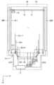
도 1을 참조하면, 상기 표시 장치는 영상이 표시 되는 표시 영역(AA) 및 상기 표시 영역(AA)에 인접하고 상기 표시 영역(AA)을 둘러싸는 비표시 영역인 주변 영역(PA)을 포함할 수 있다. 상기 표시 영역(AA)은 제1 방향(D1) 및 상기 제1 방향(D1)과 수직한 제2 방향(D2)이 이루는 평면 상에 사각형 형상을 이룰 수 있으며, 상기 표시 영역(AA)의 모서리는 라운드 형상일 수 있다. 본 실시예에 있어서, 상기 표시 영역(AA)은 라운드된 모서리를 갖는 사각형 형상이나, 이에 한정되지 않는다.Referring to FIG. 1 , the display device may include a display area AA where an image is displayed and a peripheral area PA, which is a non-display area adjacent to the display area AA and surrounding the display area AA. can The display area AA may have a rectangular shape on a plane formed by the first direction D1 and the second direction D2 perpendicular to the first direction D1, and may have a corner of the display area AA. may have a round shape. In this embodiment, the display area AA has a rectangular shape with rounded corners, but is not limited thereto.
상기 주변 영역(PA)은 상기 표시 영역(AA)의 좌측에 인접하는 좌측 주변 영역, 상기 표시 영역(AA)의 우측에 인접하는 우측 주변영역, 상기 표시 영역(AA)의 상측에 인접하는 상측 주변 영역 및 상기 표시 영역(AA)의 하측에 인접하는 하측 주변 영역을 포함할 수 있다.The peripheral area PA includes a left peripheral area adjacent to the left side of the display area AA, a right peripheral area adjacent to the right side of the display area AA, and an upper peripheral area adjacent to the upper side of the display area AA. It may include an area and a lower peripheral area adjacent to a lower side of the display area AA.
이때, 상기 하측 주변 영역에 구동부를 연결하기 위한 데이터 패드(COP) 및 게이트 패드(FOP)가 배치되므로, 상기 하측 주변 영역은 상기 상측, 좌측 및 우측 주변 영역 보다 큰 폭으로 형성될 수 있다. 상기 하측 주변 영역은 상기 표시 영역(AA)에 바로 인접하는 제1 주변 영역(PAa), 벤딩 영역(BA) 및 제2 주변 영역(PAb)을 포함할 수 있다. 상기 데이터 패드(COP) 및 상기 게이트 패드(FOP)는 상기 제2 주변 영역(PAb)에 배치될 수 있다.In this case, since the data pad COP and the gate pad FOP for connecting the driver are disposed in the lower peripheral area, the lower peripheral area may have a larger width than the upper, left, and right peripheral areas. The lower peripheral area may include a first peripheral area PAa, a bending area BA, and a second peripheral area PAb immediately adjacent to the display area AA. The data pad COP and the gate pad FOP may be disposed in the second peripheral area PAb.
상기 벤딩 영역(BA)은 상기 제2 주변 영역(PAb)을 상기 표시 장치의 후면에 배치시키기 위해 접히는 부분으로, 상기 제1 주변 영역(PAa)과 상기 제2 주변 영역(PAb) 사이에 배치될 수 있다.The bending area BA is a bent portion to arrange the second peripheral area PAb on the rear surface of the display device, and is disposed between the first and second peripheral areas PAa and PAb. can
이때, 상기 벤딩 영역(BA)의 상기 제1 방향(D1)으로의 길이는 상기 표시 영역(AA)의 상기 제1 방향(D1)으로의 길이 보다 작을 수 있다. 이에 따라, 하측 주변 영역에 배치되는 데이터 스파이더 라인(DSPL) 보다 상기 제1 방향(D1)으로 바깥쪽에 위치하는 데이터 라인들은 연결 라인(CL)을 통해 상기 데이터 스파이더 라인(DSPL)과 연결될 수 있다.In this case, the length of the bending area BA in the first direction D1 may be smaller than the length of the display area AA in the first direction D1. Accordingly, data lines positioned outside the data spider line DSPL disposed in the lower peripheral area in the first direction D1 may be connected to the data spider line DSPL through the connection line CL.
상기 데이터 스파이더 라인(DSPL)은 상기 표시 영역(AA) 내의 데이터 라인 및 상기 데이터 패드(COP)와 전기적으로 연결될 수 있다. 한편, 상기 하측 주변 영역의 상기 데이터 스파이더 라인(DSPL)과 인접하는 부분에는 스캔 구동부 또는 데이터 구동부와 연결되고, 게이트 패드(COP)와 연결되는 게이트 스파이더 라인(GSPL)이 배치될 수 있다.The data spider line DSPL may be electrically connected to a data line in the display area AA and the data pad COP. Meanwhile, a gate spider line GSPL connected to a scan driver or data driver and connected to a gate pad COP may be disposed in a portion adjacent to the data spider line DSPL in the lower peripheral area.
상기 데이터 패드(COP)에는 데이터 구동부를 포함하는 칩(chip)이 연결될 수 있다. 상기 게이트 패드(COP)에는 타이밍 제어부를 포함하는 구동 기판이 연결될 수 있다.A chip including a data driver may be connected to the data pad COP. A driving substrate including a timing controller may be connected to the gate pad COP.
도 2는 도 1의 본 발명의 일 실시예에 따른 화소들 및 구동부의 실시예를 나타낸 블록도이다. 도 4는 도 1의 표시 장치의 좌측 하단 부분의 확대도이다. 도 5는 도 4의 표시 장치의 데이터 라인 및 연결 라인의 연결 관계를 설명하기 위한 도면이다.FIG. 2 is a block diagram illustrating an example of pixels and a driving unit according to an exemplary embodiment of the present invention of FIG. 1 . FIG. 4 is an enlarged view of a lower left portion of the display device of FIG. 1 . FIG. 5 is a diagram for explaining a connection relationship between data lines and connection lines of the display device of FIG. 4 .
도 1 내지 5를 참조하면, 상기 표시 장치는 복수의 화소들(PX), 구동부, 및 배선부를 포함한다.1 to 5 , the display device includes a plurality of pixels PX, a driving unit, and a wiring unit.
상기 구동부는 스캔 구동부(SDV), 발광 구동부(EDV), 데이터 구동부(DD), 및 타이밍 제어부(TC)를 포함한다. 도 2에 있어서, 상기 스캔 구동부(SDV), 상기 발광 구동부(EDV), 상기 데이터 구동부(DDV), 및 상기 타이밍 제어부(TC)의 위치는 설명의 편의를 위해 설정된 것으로서, 실제 표시 장치를 구현할 때는 표시 장치 내에서의 다른 위치에 배치될 수 있다.The driving unit includes a scan driving unit SDV, a light emitting driving unit EDV, a data driving unit DD, and a timing controller TC. In FIG. 2 , positions of the scan driving unit SDV, the light emitting driving unit EDV, the data driving unit DDV, and the timing controller TC are set for convenience of description. It may be arranged at a different position within the display device.
상기 배선부는 상기 구동부의 신호를 각 화소(PX)에 제공하며, 스캔 라인들(SL), 데이터 라인들(DL1,, DLn-1, DLn, DLn+1,) 및 발광 제어 라인들(EL), 제1 및 제2 전원 라인들(미도시), 및 초기화 전원 라인(미도시)을 포함한다.The wiring unit provides signals of the driving unit to each pixel PX, and includes scan lines SL, data lines DL1, DLn−1, DLn, DLn+1, and emission control lines EL. , first and second power lines (not shown), and an initialization power line (not shown).
상기 스캔 라인, 상기 데이터 라인 및 상기 발광 제어 라인은 각각의 화소(PX)에 전기적으로 연결될 수 있다.The scan line, the data line, and the emission control line may be electrically connected to each pixel PX.
상기 화소들(PX)은 상기 스캔 라인들(SL)로부터 스캔 신호가 공급될 때 데이터 라인들(DL1,, DLn-1, DLn, DLn+1,)로부터 데이터 신호를 공급받는다. 상기 데이터 신호를 공급받은 상기 화소들(PX)은 제1 전원(ELVDD)으로부터 유기 발광 소자(미도시)를 경유하여 제2 전원(ELVSS)으로 흐르는 전류량을 제어할 수 있다.The pixels PX receive data signals from data lines DL1, DLn−1, DLn, DLn+1, when scan signals are supplied from the scan lines SL. The pixels PX receiving the data signal may control the amount of current flowing from the first power source ELVDD to the second power source ELVSS via an organic light emitting element (not shown).
상기 스캔 구동부(SDV)는 상기 타이밍 제어부(TC)로부터의 제1 게이트 제어 신호(GCS1)에 대응하여 상기 스캔 라인들(SL)로 스캔 신호를 공급할 수 있다. 상기 스캔 라인들(SL)로 스캔 신호가 순차적으로 공급되면 상기 화소들(PX)이 수평라인 단위로 순차적으로 선택될 수 있다.The scan driver SDV may supply scan signals to the scan lines SL in response to the first gate control signal GCS1 from the timing controller TC. When scan signals are sequentially supplied to the scan lines SL, the pixels PX may be sequentially selected in units of horizontal lines.
상기 발광 구동부(EDV)는 상기 타이밍 제어부(TC)로부터의 제2 게이트 제어 신호(GCS2)에 대응하여 상기 발광 제어 라인들(EL)로 발광 제어 신호를 공급할 수 있다. 상기 발광 구동부(EDV)는 상기 발광 제어 라인들(EL)로 발광 제어 신호를 순차적으로 공급할 수 있다.The light emitting driver EDV may supply light emitting control signals to the light emitting control lines EL in response to the second gate control signal GCS2 from the timing controller TC. The light emitting driver EDV may sequentially supply light emitting control signals to the light emitting control lines EL.
추가적으로, 상기 발광 제어 신호는 상기 화소들(PX)에 포함되는 트랜지스터가 턴-오프될 수 있도록 게이트 오프 전압(예를 들면, 하이 전압)으로 설정되고, 스캔 신호는 화소들(PXL)에 포함되는 트랜지스터가 턴-온될 수 있도록 게이트 온 전압(예를 들면, 로우 전압)으로 설정될 수 있다.Additionally, the emission control signal is set to a gate-off voltage (eg, a high voltage) so that the transistor included in the pixels PX can be turned off, and the scan signal is included in the pixels PXL. It can be set to a gate-on voltage (eg, low voltage) so that the transistor can be turned on.
상기 데이터 구동부(DDV)는 데이터 제어 신호(DCS)에 대응하여 상기 데이터 라인들(DL1,, DLn-1, DLn, DLn+1,)로 데이터 신호를 공급할 수 있다. 상기 데이터 라인들(DL1,, DLn-1, DLn, DLn+1,)로 공급된 상기 데이터 신호는 상기 스캔 신호에 의하여 선택된 화소들(PX)로 공급된다.The data driver DDV may supply data signals to the data lines DL1, DLn−1, DLn, DLn+1, in response to the data control signal DCS. The data signals supplied to the data lines DL1, DLn−1, DLn, and DLn+1 are supplied to the pixels PX selected by the scan signal.
상기 타이밍 제어부(TC)는 외부로부터 공급되는 타이밍 신호들에 기초하여 생성된 상기 제1 및 제2 게이트 제어 신호들(GCS1, GCS2)을 상기 스캔 구동부(SDV) 및 상기 발광 구동부들(EDV)로 공급하고, 데이터 제어 신호(DCS)를 상기 데이터 구동부(DD)로 공급한다.The timing controller TC transmits the first and second gate control signals GCS1 and GCS2 generated based on timing signals supplied from the outside to the scan driver SDV and the light emission driver EDV. and supplies the data control signal DCS to the data driver DD.
상기 제1 및 제2 게이트 제어 신호들(GCS1, GCS2) 각각에는 스타트 펄스 및 클럭 신호들이 포함될 수 있다. 상기 스타트 펄스는 첫번째 스캔 신호 또는 첫번째 발광 제어 신호의 타이밍을 제어할 수 있다. 상기 클럭 신호들은 상기 스타트 펄스를 쉬프트시키기 위하여 사용될 수 있다.Each of the first and second gate control signals GCS1 and GCS2 may include a start pulse and clock signals. The start pulse may control timing of a first scan signal or a first emission control signal. The clock signals may be used to shift the start pulse.
상기 데이터 제어 신호(DCS)에는 상기 소스 스타트 펄스 및 상기 클럭 신호들이 포함될 수 있다. 상기 소스 스타트 펄스는 데이터의 샘플링 시작 시점을 제어한다. 상기 클럭 신호들은 샘플링 동작을 제어하기 위하여 사용될 수 있다.The data control signal DCS may include the source start pulse and the clock signals. The source start pulse controls data sampling start time. The clock signals may be used to control the sampling operation.
여기서, 상기 데이터 라인은 제1 데이터 라인(DL1), 제(n-1)번째 데이터 라인(DLn-1), 제(n)번째 데이터 라인(DLn) 및 제(n+1)번째 데이터 라인(DLn+1)을 포함할 수 있다.Here, the data lines include the first data line DL1, the (n−1)th data line DLn−1, the (n)th data line DLn, and the (n+1)th data line ( DLn+1).
상기 제1 데이터 라인(DL1), 상기 제(n-1)번째 데이터 라인(DLn-1), 상기 제(n)번째 데이터 라인(DLn) 및 상기 제(n+1)번째 데이터 라인(DLn+1)은 제1 방향(D1)을 따라 배열되고, 상기 제1 방향(D1)에 수직한 제2 방향(D2)을 따라 연장될 수 있다.The first data line DL1, the (n−1)th data line DLn−1, the (n)th data line DLn, and the (n+1)th data line DLn+ 1) may be arranged along the first direction D1 and may extend along the second direction D2 perpendicular to the first direction D1.
상기 데이터 라인은 연결 콘택홀(CCNT)을 통해 연결 라인(CL)과 연결되고, 상기 연결 라인(CL)은 스파이더 콘택홀(SCNT)을 통해 스파이더 라인(SPDL)과 연결되거나, 상기 데이터 라인은 스파이더 콘택홀(SCNT)을 통해 스파이더 라인(SPDL)과 직접 연결될 수 있다.The data line is connected to the connection line CL through the connection contact hole CCNT, and the connection line CL is connected to the spider line SPDL through the spider contact hole SCNT. It may be directly connected to the spider line SPDL through the contact hole SCNT.
예를 들면, 상기 제1 데이터 라인(DL1)은 제1 연결 콘택홀(CCNT1)을 통해 제1 연결 라인(CL)과 연결될 수 있다. 상기 연결 콘택홀은 상기 주변 영역(PA)내에서 형성될 수 있다. 상기 제1 연결 라인(CL)은 상기 표시 영역(AA)을 지나, 상기 주변 영역(PA)에서 제1 데이터 스파이더 라인(DSPL1)과 제1 스파이더 콘택홀(SCNT1)을 통해 연결될 수 있다. 이때, 상기 제1 연결 라인(CL)은 상기 제2 방향(D2)으로 연장되는 제1 부분(CL1a), 상기 제1 부분(CL1a)과 연결되고 상기 제1 방향(D2)으로 연장되는 제2 부분(CL1b) 및 상기 제1 부분(CL1a)과 평행한 제3 부분(CL1c)을 포함할 수 있다.For example, the first data line DL1 may be connected to the first connection line CL through a first connection contact hole CCNT1. The connection contact hole may be formed in the peripheral area PA. The first connection line CL may pass through the display area AA and be connected to the first data spider line DSPL1 through the first spider contact hole SCNT1 in the peripheral area PA. In this case, the first connection line CL is connected to a first portion CL1a extending in the second direction D2 and a second portion CL1a connected to the first portion CL1a and extending in the first direction D2. A portion CL1b and a third portion CL1c parallel to the first portion CL1a may be included.
상기 제(n-1)번째 데이터 라인(DL1)은 상기 표시 영역(AA)의 하측의 상기 주변 영역(PA)내에서 연결 콘택홀(CCNT)을 통해 제(n-1)번째 연결 라인(CLn-1)과 연결될 수 있다. 상기 제(n-1)번째 연결 라인(CLn-1)은 상기 표시 영역(AA)을 지나, 상기 주변 영역(PA)에서 데이터 스파이더 라인(DSPL)과 스파이더 콘택홀(SCNT)을 통해 연결될 수 있다.The (n−1)th data line DL1 is connected to the (n−1)th connection line CLn through a connection contact hole CCNT in the peripheral area PA below the display area AA. -1) can be connected. The (n−1)th connection line CLn−1 passes through the display area AA and is connected to the data spider line DSPL and the spider contact hole SCNT in the peripheral area PA. .
한편, 상기 제(n)번째 데이터 라인(DLn) 및 상기 제(n+1)번째 데이터 라인(DLn+1)은 연결 라인을 통하지 않고, 상기 주변 영역(PA)에서 데이터 스파이더 라인(DSPL)과 스파이더 콘택홀(SCNT)을 통해 직접 연결될 수 있다. 도 5에서는 n이 589인 경우가 개념적으로 도시되어 있다.Meanwhile, the (n)th data line DLn and the (n+1)th data line DLn+1 do not pass through a connection line and are connected to the data spider line DSPL in the peripheral area PA. It can be directly connected through a spider contact hole (SCNT). In FIG. 5, the case where n is 589 is conceptually shown.
여기서, 상기 데이터 스파이더 라인들(DSPL1, DSPL)은 상기 벤딩 영역(BA)과 상기 표시 영역(AA) 사이의 상기 주변 영역(PA)에서, 각각이 상기 제2 방향으로 연장되고 서로 평행하게 배치될 수 있다. 이에 따라 상기 데이터 스파이더 라인들(DSPL1, DSPL)이 상기 제2 방향(D2)에 소정각도 꺽인 형상인 종래 기술에 비해, 상기 데이터 스파이더 라인들(DSPL1, DSPL) 간의 거리를 충분히 확보 할 수 있으며, 이에 따라, 상기 데이터 스파이더 라인들(DSPL1, DSPL)의 배선 저항을 줄일 수 있다.Here, the data spider lines DSPL1 and DSPL may extend in the second direction and be parallel to each other in the peripheral area PA between the bending area BA and the display area AA. can Accordingly, compared to the prior art in which the data spider lines DSPL1 and DSPL are bent at a predetermined angle in the second direction D2, a sufficient distance between the data spider lines DSPL1 and DSPL can be secured. Accordingly, wiring resistance of the data spider lines DSPL1 and DSPL may be reduced.
본 실시예에 따르면, 상기 표시 장치는 영상이 표시 되는 표시 영역 및 비표시 영역인 주변 영역을 포함한다. 상기 표시 장치는 베이스 기판, 상기 베이스 기판 상에 상기 표시 영역에 배치되는 제1 데이터 라인, 상기 베이스 기판 상에 적어도 일부가 상기 표시 영역에 배치되고, 연결 콘택홀을 통해 상기 제1 데이터 라인과 전기적으로 연결되는 제1 연결 라인, 상기 주변 영역에 배치되는 데이터 패드부, 및 상기 데이터 패드부와 상기 표시 영역 사이의 상기 주변 영역에 배치되어, 상기 제1 연결 라인 및 상기 데이터 패드와 전기적으로 연결되는 제1 데이터 스파이더 라인을 포함한다. 상기 제1 연결 라인이 상기 주변 영역이 아닌 상기 표시 영역 내에 배치되므로, 상기 주변부의 폭을 줄여 비표시 영역인 베젤 부분을 줄인 표시 장치를 구현할 수 있다.According to this embodiment, the display device includes a display area where an image is displayed and a peripheral area which is a non-display area. The display device includes a base substrate, a first data line disposed in the display area on the base substrate, at least a portion of the base substrate disposed in the display area, and electrically connected to the first data line through a connection contact hole. A first connection line connected to, a data pad portion disposed in the peripheral area, and disposed in the peripheral area between the data pad portion and the display area and electrically connected to the first connection line and the data pad. It includes a first data spider line. Since the first connection line is disposed in the display area instead of the peripheral area, a display device in which a bezel portion, which is a non-display area, may be reduced by reducing a width of the peripheral portion may be implemented.
한편, 본 실시예에 있어서, 상기 스캔 구동부(SDV)는 표시 영역(AA)의 좌측에 인접하는 주변 영역(PA)에 배치되고, 상기 발광 구동부(EDV)는 상기 표시 영역(AA)의 우측에 인접하는 주변 영역(PA)에 배치되는 것으로 설명되었으나, 이에 한정되지 않는다. 예를 들면, 좌측 및 우측 주변 영역 모두에 스캔 라인 및 발광 제어 라인으로 서로 연결되는 스캔 구동부 및 발광 구동부가 배치되어, 화소들에 좌측 및 우측에서 서로 동기화된 신호를 공급하도록 할 수 있다.Meanwhile, in the present embodiment, the scan driver SDV is disposed in the peripheral area PA adjacent to the left side of the display area AA, and the light emitting driver EDV is disposed in the right side of the display area AA. Although it has been described as being disposed in the adjacent peripheral area PA, it is not limited thereto. For example, a scan driver and a light emitting driver connected to each other by a scan line and a light emitting control line may be disposed in both the left and right peripheral regions to supply signals synchronized with each other on the left and right sides to the pixels.
도 3을 다시 참조하면, 설명의 편의성을 위하여 제m 데이터 라인(Dm) 및 i번째 제1 스캔 라인(S1i)에 접속된 화소를 도시하기로 한다.Referring back to FIG. 3 , for convenience of explanation, a pixel connected to the m th data line Dm and the i th first scan line S1i will be illustrated.
본 발명의 실시예에 의한 화소(PX)는 유기 발광 소자(OLED), 제1 트랜지스터(T1) 내지 제7 트랜지스터(T7) 및 스토리지 커패시터(Cst)를 구비할 수 있다.The pixel PX according to an embodiment of the present invention may include an organic light emitting diode (OLED), first to seventh transistors T1 to T7 , and a storage capacitor Cst.
상기 유기 발광 소자(OLED)의 애노드는 상기 제6 트랜지스터(T6)를 경유하여 상기 제1 트랜지스터(T1)에 접속되고, 캐소드는 제2 전원(ELVSS)에 접속될 수 있다. 이와 같은 유기 발광 소자(OLED)는 상기 제1 트랜지스터(T1)로부터 공급되는 전류량에 대응하여 소정 휘도의 빛을 생성할 수 있다.An anode of the organic light emitting diode OLED may be connected to the first transistor T1 via the sixth transistor T6, and a cathode may be connected to the second power source ELVSS. Such an organic light emitting diode (OLED) can generate light with a predetermined luminance in response to the amount of current supplied from the first transistor (T1).
상기 유기 발광 소자(OLED)로 전류가 흐를 수 있도록 제1 전원(ELVDD)은 제2 전원(ELVSS)보다 높은 전압으로 설정될 수 있다.The first power source ELVDD may be set to a higher voltage than the second power source ELVSS so that current can flow through the organic light emitting diode OLED.
상기 제7 트랜지스터(T7)는 초기화 전원(Vint)과 상기 유기 발광 소자(OLED)의 애노드 사이에 접속될 수 있다. 그리고, 상기 제7 트랜지스터(T7)의 게이트 전극은 i+1 번째 제1 스캔 라인(S1i+1) 또는 i-1 번째 제1 스캔 라인(S1i-1)에 접속될 수 있다. 이와 같은 상기 제7 트랜지스터(T7)는 i번째 제1스캔 라인(S1i)으로 스캔 신호가 공급될 때 턴-온되어 초기화 전원(Vint)의 전압을 상기 유기 발광 소자(OLED)의 애노드로 공급할 수 있다. 여기서, 초기화 전원(Vint)은 데이터 신호보다 낮은 전압으로 설정될 수 있다.The seventh transistor T7 may be connected between the initialization power supply Vint and the anode of the organic light emitting diode OLED. Also, the gate electrode of the seventh transistor T7 may be connected to the i+1 th first scan line S1i+1 or the i−1 th first scan
상기 제6 트랜지스터(T6)는 상기 제1 트랜지스터(T1)와 상기 유기 발광 소자(OLED) 사이에 접속된다. 그리고, 상기 제6 트랜지스터(T6) 게이트 전극은 i번째 제1 발광 제어 라인(E1i)에 접속될 수 있다. 이와 같은 제6 트랜지스터(T6)는 i번째 제1 발광 제어 라인(E1i)으로 발광 제어 신호가 공급될 때 턴-오프되고, 그 외의 경우에 턴-온될 수 있다.The sixth transistor T6 is connected between the first transistor T1 and the organic light emitting diode OLED. Also, the gate electrode of the sixth transistor T6 may be connected to the i-th first emission control line E1i. The sixth transistor T6 is turned off when an emission control signal is supplied to the i-th first emission control line E1i, and may be turned on in other cases.
상기 제5 트랜지스터(T5)는 상기 제1 전원(ELVDD)과 상기 제1 트랜지스터(T1) 사이에 접속될 수 있다. 그리고, 상기 제5 트랜지스터(T5)의 게이트 전극은 i번째 제1 발광 제어 라인(E1i)에 접속될 수 있다. 이와 같은 상기 제5 트랜지스터(T5)는 i번째 제1 발광 제어 라인(E1i)으로 발광 제어 신호가 공급될 때 턴-오프되고, 그 외의 경우에 턴-온될 수 있다.The fifth transistor T5 may be connected between the first power source ELVDD and the first transistor T1. A gate electrode of the fifth transistor T5 may be connected to the i-th first emission control line E1i. The fifth transistor T5 is turned off when an emission control signal is supplied to the i-th first emission control line E1i, and may be turned on in other cases.
상기 제1 트랜지스터(T1; 구동 트랜지스터)의 제1 전극은 상기 제5 트랜지스터(T5)를 경유하여 제1 전원(ELVDD)에 접속되고, 제2 전극은 상기 제6 트랜지스터(T6)를 경유하여 상기 유기 발광 소자(OLED)의 애노드에 접속될 수 있다. 그리고, 상기 제1 트랜지스터(T1)의 게이트 전극은 제1 노드(N1)에 접속될 수 있다. 이와 같은 상기 제1 트랜지스터(T1)는 제1 노드(N1)의 전압에 대응하여 상기 제1 전원(ELVDD)으로부터 상기 유기 발광 소자(OLED)를 경유하여 상기 제2 전원(ELVSS)으로 흐르는 전류량을 제어할 수 있다.The first electrode of the first transistor T1 (driving transistor) is connected to the first power source ELVDD via the fifth transistor T5, and the second electrode connects the sixth transistor T6 to the first power source ELVDD. It may be connected to the anode of the organic light emitting diode (OLED). Also, a gate electrode of the first transistor T1 may be connected to a first node N1. The first transistor T1 controls the amount of current flowing from the first power source ELVDD to the second power source ELVSS via the organic light emitting diode OLED in response to the voltage of the first node N1. You can control it.
상기 제3 트랜지스터(T3)는 상기 제1 트랜지스터(T1)의 제2 전극과 상기 제1 노드(N1) 사이에 접속될 수 있다. 그리고, 상기 제3 트랜지스터(T3)의 게이트 전극은 i번째 제1 스캔 라인(S1i)에 접속될 수 있다. 이와 같은 상기 제3 트랜지스터(T3)는 i번째 제1 스캔 라인(S1i)으로 스캔 신호가 공급될 때 턴-온되어 상기 제1 트랜지스터(T1)의 제2 전극과 제1 노드(N1)를 전기적으로 접속시킬 수 있다. 따라서, 상기 제3 트랜지스터(T3)가 턴-온 될 때 제1 트랜지스터(T1)는 다이오드 형태로 접속될 수 있다.The third transistor T3 may be connected between the second electrode of the first transistor T1 and the first node N1. A gate electrode of the third transistor T3 may be connected to the i-th first scan line S1i. The third transistor T3 is turned on when a scan signal is supplied to the i-th first scan line S1i and electrically connects the second electrode of the first transistor T1 to the first node N1. can be connected to. Accordingly, when the third transistor T3 is turned on, the first transistor T1 may be connected in a diode form.
상기 제4 트랜지스터(T4)는 제1 노드(N1)와 초기화 전원(Vint) 사이에 접속될 수 있다. 그리고, 상기 제4 트랜지스터(T4)의 게이트 전극은 i-1번째 제1 스캔 라인(S1i-1)에 접속될 수 있다. 이와 같은 상기 제4 트랜지스터(T4)는 i-1번째 제1 스캔 라인(S1i-1)으로 스캔 신호가 공급될 때 턴-온되어 상기 제1 노드(N1)로 초기화 전원(Vint)의 전압을 공급할 수 있다.The fourth transistor T4 may be connected between the first node N1 and the initialization power source Vint. Also, the gate electrode of the fourth transistor T4 may be connected to the i−1 th first scan
상기 제2 트랜지스터(T2)는 제m 데이터 라인(Dm)과 제1 트랜지스터(T1)의 제1 전극 사이에 접속될 수 있다. 그리고, 상기 제2 트랜지스터(T2)의 게이트 전극은 i번째 제1 스캔 라인(S1i)에 접속될 수 있다. 이와 같은 상기 제2 트랜지스터(T2)는 i번째 제1 스캔 라인(S1i)으로 스캔 신호가 공급될 때 턴-온되어 제m 데이터 라인(Dm)과 상기 제1 트랜지스터(T1)의 제1 전극을 전기적으로 접속시킬 수 있다.The second transistor T2 may be connected between the mth data line Dm and the first electrode of the first transistor T1. Also, a gate electrode of the second transistor T2 may be connected to the i-th first scan line S1i. The second transistor T2 is turned on when a scan signal is supplied to the i-th first scan line S1i to connect the m-th data line Dm and the first electrode of the first transistor T1. can be electrically connected.
상기 스토리지 커패시터(Cst)는 상기 제1 전원(ELVDD)과 상기 제1 노드(N1) 사이에 접속될 수 있다. 이와 같은 스토리지 커패시터(Cst)는 데이터 신호 및 상기 제1 트랜지스터(T1)의 문턱전압에 대응하는 전압을 저장할 수 있다.The storage capacitor Cst may be connected between the first power source ELVDD and the first node N1. The storage capacitor Cst may store a data signal and a voltage corresponding to the threshold voltage of the first transistor T1.
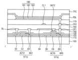
도 6은 도 4의 I-I'선을 따라 절단한 표시 장치의 단면도이다. 도 7은 도 4의 II-II'선을 따라 절단한 표시 장치의 일부 층에 대한 단면도이다.FIG. 6 is a cross-sectional view of the display device taken along line II′ of FIG. 4 . FIG. 7 is a cross-sectional view of some layers of the display device taken along line II-II′ of FIG. 4 .
도 4 내지 7을 참조하면, 상기 표시 장치는 베이스 기판(100), 버퍼층(110), 액티브 패턴(ACT), 제1 게이트 절연층(120), 제1 게이트 패턴, 제2 게이트 절연층(130), 제2 게이트 패턴(GAT2), 층간 절연층(140), 제1 데이터 패턴, 제1 절연층(160), 연결 라인 패턴, 제2 절연층(170), 화소 정의막(PDL), 발광 구조물(180), 박막 봉지층(TFE)을 포함할 수 있다.4 to 7 , the display device includes a
상기 베이스 기판(100)은 투명 절연 기판을 포함할 수 있다. 예를 들면, 상기 베이스 기판(100)은 가요성(flexible)이 있는 상기 투명 수지 기판일 수 있다. 상기 투명 수지 기판은 폴리이미드계(polyimide-based) 수지, 아크릴계(acryl-based) 수지, 폴리아크릴레이트계(polyacrylate-based) 수지, 폴리카보네이트계(polycarbonate-based) 수지, 폴리에테르계(polyether-based) 수지, 술폰산계(sulfonic acid-based) 수지, 폴리에틸렌테레프탈레이트계(polyethyleneterephthalate-based) 수지 등을 포함할 수 있다. 바람직하게는 상기 베이스 기판(100)은 폴리 이미드(PI) 수지 필름 일 수 있다.The
상기 버퍼층(110)은 상기 베이스 기판(100)으로부터 금속 원자들이나 불순물들이 확산되는 현상을 방지할 수 있으며, 후술할 액티브 패턴(ACT)을 형성하기 위한 결정화 공정 동안 열의 전달 속도를 조절하여 실질적으로 균일한 액티브 패턴(ACT)을 수득하게 할 수 있다. 또한, 상기 버퍼층(110)은 상기 베이스 기판(100)의 표면이 균일하지 않을 경우, 상기 베이스 기판(100)의 표면의 평탄도를 향상시키는 역할을 수행할 수도 있다. 상기 버퍼층(110)은 실리콘 산화물(SiOx), 실리콘 질화물(SiNx), 실리콘 산질화물(SiOxNy), 실리콘 산탄화물(SiOxCy), 실리콘 탄질화물(SiCxNy) 등 의 실리콘 화합물을 사용하여 형성될 수 있다.The
상기 버퍼층(110)은 상기 주변 영역(PA)의 벤딩 영역(BA)에 대해서는 형성되지 않을 수 있다. 즉, 상기 버퍼층(110)은 상기 벤딩 영역(FA)에는 형성되지 않거나, 제거될 수 있다. 이는, 상기 벤딩 영역(BA)은 최종 제품에 있어서, 접혀지는 부분이므로, 무기막인 상기 버퍼층(110)이 상기 벤딩 영역(BA)에 형성되면, 상기 버퍼층(110)에 크랙(crack) 등의 손상이 발생될 수 있기 때문이다. 이와 마찬가지로, 무기막으로 형성되는 절연층들(120, 130, 등)은 상기 벤딩 영역(BA)에 대해서는 형성되지 않을 수 있다.The
상기 액티브 패턴(ACT1, ACT2)이 상기 버퍼층(110) 상에 배치될 수 있다. 상기 액티브 패턴(ACT1, ACT2)은 상기 표시 영역(DA) 내에 배치되어 화소 구조를 이루는 박막 트랜지스터(TFT2, TFT6) 및 상기 주변 영역(PA) 내에 배치되어, 구동 회로를 이루는 액티브 패턴(미도시)을 포함할 수 있다. 상기 구동 회로는 ASG(아몰퍼스 실리콘 게이트) 회로 일 수 있다.The active patterns ACT1 and ACT2 may be disposed on the
상기 박막 트랜지스터(TFT2, TFT6)의 각각의 상기 액티브 패턴(ACT1, ACT2)은 불순물이 도핑(doping)된 드레인 영역(D2, D6)과 소스 영역(S2, S6) 및 상기 드레인 영역(D2, D6)과 상기 소스 영역(S2, S6) 사이의 채널 영역(C2, C6)을 포함할 수 있다. 상기 박막 트랜지스터(TFT2, TFT6)는 각각 도 3의 제2 트랜지스터 및 제6 트랜지스터일 수 있다.Each of the active patterns ACT1 and ACT2 of the thin film transistors TFT2 and TFT6 includes impurity-doped drain regions D2 and D6, source regions S2 and S6, and the drain regions D2 and D6. ) and the channel regions C2 and C6 between the source regions S2 and S6. The thin film transistors TFT2 and TFT6 may be the second transistor and the sixth transistor of FIG. 3 , respectively.
상기 제1 게이트 절연층(120)은 상기 액티브 패턴(ACT1, ACT2)이 배치된 상기 버퍼층(110) 상에 배치될 수 있다. 상기 제1 게이트 절연층(120)은 실리콘 화합물, 금속 산화물 등을 포함할 수 있다.The first
상기 제1 게이트 패턴은 상기 게이트 절연층(120) 상에 배치될 수 있다. 상기 제1 게이트 패턴은 상기 박막 트랜지스터(TFT2, TFT6)의 게이트 전극(GE) 및 상기 화소를 구동하기 위한 신호를 전달하는 게이트 라인과 같은 신호 라인 등을 포함할 수 있다. 상기 제1 게이트 패턴은 금속, 합금, 금속 질화물, 도전성 금속 산화물, 투명 도전성 물질 등을 사용하여 형성될 수 있다. 예를 들면, 상기 제1 게이트 패턴은 구리, 알루미늄, 몰리브덴 등의 금속으로 형성될 수 있다. 또한, 상기 제1 게이트 패턴은 복수의 층상 구조를 가질 수 있다. 예를 들면, 상기 게이트 도전 패턴은 구리 층 및 상기 구리 층 상의 몰리브덴 층을 포함할 수 있다.The first gate pattern may be disposed on the
상기 제2 게이트 절연층(130) 상기 제1 게이트 패턴이 배치된 상기 제1 게이트 절연층(120) 상에 배치될 수 있다. 상기 제2 게이트 절연층(130)은 실리콘 산화물(SiOx), 실리콘 질화물(SiNx), 실리콘 산질화물(SiOxNy), 실리콘 산탄화물(SiOxCy), 실리콘 탄질화물(SiCxNy) 등 의 실리콘 화합물을 사용하여 형성될 수 있다.The second
상기 제2 게이트 패턴(GAT2)이 상기 제2 게이트 절연층(130) 상에 배치될 수 있다. 상기 제2 게이트 패턴(GAT2)은 금속, 합금, 금속 질화물, 도전성 금속 산화물, 투명 도전성 물질 등을 사용하여 형성될 수 있다. 예를 들면, 상기 제2 게이트 패턴(GAT2)은 구리, 알루미늄, 몰리브덴 등의 금속으로 형성될 수 있다. 또한, 상기 제2 게이트 패턴(GAT2)은 복수의 층상 구조를 가질 수 있다. 예를 들면, 상기 제2 게이트 패턴(GAT2)은 구리 층 및 상기 구리 층 상의 몰리브덴 층을 포함할 수 있다.The second gate pattern GAT2 may be disposed on the second
여기서, 데이터 스파이더 라인(DSPL)은 상기 제1 게이트 패턴 및 상기 제2 게이트 패턴으로 번갈아 가며 형성될 수 있다. 즉, 도 7에 도시된 바와 같이 인접하는 두개의 데이터 스파이더 라인(DSPL)은 서로 다른 층에 형성되어, 각각의 데이터 스파이더 라인(DSPL)의 선폭을 최대화 할 수 있으며, 이에 따라 하나의 데이터 스파이더 라인(DSPL)을 배치시키기 위한 폭(W)가 최소화 될 수 있다.Here, the data spider line DSPL may be alternately formed with the first gate pattern and the second gate pattern. That is, as shown in FIG. 7, two adjacent data spider lines (DSPL) are formed on different layers to maximize the line width of each data spider line (DSPL), and thus form one data spider line. A width W for arranging the DSPL may be minimized.
상기 층간 절연층(140)은 상기 제2 게이트 패턴(GAT2)이 배치된 상기 제2 게이트 절연층(130) 상에 배치될 수 있다.The interlayer insulating
상기 제1 데이터 패턴이 상기 층간 절연층(140) 상에 배치될 수 있다. 상기 제1 데이터 패턴은 데이터 라인(DL), 쉴딩 전극(SH) 및 제1 콘택 패드(CP1)를 포함할 수 있다. 상기 제1 데이터 패턴은 금속, 합금, 금속 질화물, 도전성 금속 산화물, 투명 도전성 물질 등을 사용하여 형성될 수 있다. 예를 들면, 상기 제1 데이터 패턴은 전도성이 높은 구리, 알루미늄 등의 금속으로 형성될 수 있다. 상기 제1 데이터 패턴은 복수의 층상 구조를 가질 수 있다. 예를 들면, 상기 제1 데이터 패턴은 티타늄 층, 상기 티타늄 층 상의 알루미늄 층 및 상기 알루미늄 층 상의 티타늄을 포함할 수 있다.The first data pattern may be disposed on the
상기 쉴딩 전극(SH)에는 제1 전원 전압(ELVDD)이 인가되어, 상기 제1 연결 라인(CL)과 다른 화소 구조 간의 커플링 커패시터 형성을 방지할 수 있다. 상기 쉴드 전극(SH)은 상기 박막 트랜지스터(TFT)와 상기 제1 연결 라인(CL1) 사이에 배치될 수 있다. 상기 쉴딩 전극(SH)은 상기 데이터 라인(DL)과 평행하게 연장되는 제1 전원 배선의 일부 일 수 있다.A first power supply voltage ELVDD may be applied to the shielding electrode SH to prevent formation of a coupling capacitor between the first connection line CL and another pixel structure. The shield electrode SH may be disposed between the thin film transistor TFT and the first connection line CL1. The shielding electrode SH may be a part of a first power line extending parallel to the data line DL.
한편, 자세히 도시하지 않았으나, 상기 제1 데이터 패턴은 상기 벤딩 영역(BA)에 있어서, 스파이더 라인(DSPL)을 구성하는 배선을 포함할 수 있다. 즉, 상기 스파이더 라인(DSPL)은 상기 벤딩 영역(BA)에서 상기 제1 데이터 패턴으로 형성되고, 상기 연결 라인(CL)과 연결되는 부분에서는 상기 제1 또는 제2 게이트 패턴으로 형성되고, 이들이 서로 콘택홀을 통해 연결될 수 있다.Meanwhile, although not shown in detail, the first data pattern may include wires constituting the spider line DSPL in the bending area BA. That is, the spider line DSPL is formed of the first data pattern in the bending area BA, and is formed of the first or second gate pattern in a portion connected to the connection line CL, and they are mutually connected to each other. They may be connected through contact holes.
상기 제1 절연층(160)은 상기 제1 데이터 패턴이 배치된 상기 층간 절연층(140) 상에 배치될 수 있다. 상기 제1 절연층(140)은 유기 절연 물질을 포함할 수 있으며, 상기 제1 데이터 패턴을 충분하게 커버하면서 실질적으로 평탄한 상면을 가질 수 있다.The first insulating
상기 제1 절연층(160) 상에 상기 연결 라인 패턴이 배치될 수 있다. 상기 연결 라인 패턴은 제1 연결 라인(CL1) 및 제2 콘택 패드(CP2)를 포함할 수 있다. 상기 연결 라인 패턴은 금속, 합금, 금속 질화물, 도전성 금속 산화물, 투명 도전성 물질 등을 사용하여 형성될 수 있다.The connection line pattern may be disposed on the first insulating
상기 제2 절연층(170)은 상기 연결 라인 패턴이 배치된 상기 제1 절연층(160) 상에 배치될 수 있다. 상기 제2 절연층(170)은 유기 절연 물질을 포함할 수 있으며, 상기 연결 라인 패턴을 충분하게 커버하면서 실질적으로 평탄한 상면을 가질 수 있다.The second
상기 발광 구조물(180)은 제1 전극(181), 발광층(182) 및 제2 전극(183)을 포함할 수 있다.The
상기 제1 전극(181)은 상기 제2 절연층(170) 상에 배치될 수 있다. 상기 제1 전극(181)은 상기 제2 절연층(170)을 통해 형성되는 콘택홀들을 통해 상기 박막 트랜지스터(TFT6)에 전기적으로 연결될 수 있다. 예를들면, 상기 제1 전극(181)은 상기 제2 콘택 패드(CP2) 및 상기 제1 콘택 패드(CP1)를 통해 상기 박막 트랜지스터(TFT6)에 연결될 수 있다.The
상기 표시 장치의 발광 방식에 따라, 상기 제1 전극(181)은 반사성을 갖는 물질 또는 투광성을 갖는 물질을 사용하여 형성될 수 있다. 예를 들면,상기 제1 전극(181)은 알루미늄, 알루미늄을 함유하는 합금, 알루미늄 질화물, 은, 은을 함유하는 합금, 텅스텐, 텅스텐 질화물, 구리, 구리를 함유하는 합금, 니켈, 크롬, 크롬 질화물, 몰리브데늄, 몰리브데늄을 함유하는 합금, 티타늄, 티타늄 질화물, 백금, 탄탈륨, 탄탈륨 질화물, 네오디뮴, 스칸듐, 스트론튬 루테늄 산화물, 아연 산화물, 인듐 주석 산화물, 주석 산화물, 인듐 산화물, 갈륨 산화물, 인듐 아연 산화물 등을 포함할 수 있다. 이들은 단독으로 또는 서로 조합되어 사용될 수 있다. 예시적인 실시예들에 있어서, 상기 제1 전극(181)은 금속막, 합금막, 금속 질화물막, 도전성 금속 산화물막 및/또는 투명 도전성 물질막을 포함하는 단층 구조 또는 다층 구조로 형성될 수 있다.Depending on the light emitting method of the display device, the
상기 화소 정의막(PDL)은 상기 제1 전극(181)이 배치된 상기 제2 절연층(170) 상에 배치될 수 있다. 상기 화소 정의막(PDL)은 유기 물질, 무기 물질 등을 사용하여 형성될 수 있다. 예를 들면, 상기 화소 정의막(PDL)은 포토레지스트, 폴리아크릴계 수지, 폴리이미드계 수지, 아크릴계 수지, 실리콘 화합물 등을 사용하여 형성될 수 있다. 예시적인 실시예들에 따르면, 상기 화소 정의막(PDL)을 식각하여 상기 제1 전극(181)을 부분적으로 노출시키는 개구(opening)를 형성할 수 있다. 이러한 상기 화소 정의막(PDL)의 개구에 의해 상기 표시 장치의 표시 영역과 비표시 영역이 정의될 수 있다. 예를 들면, 상기 화소 정의막(PDL)의 개구가 위치하는 부분이 상기 표시 영역에 해당될 수 있으며, 상기 비표시 영역은 상기 화소 정의막(PDL)의 개구에 인접하는 부분에 해당될 수 있다.The pixel defining layer PDL may be disposed on the second insulating
상기 발광층(182)은 상기 화소 정의막(PDL)의 개구를 통해 노출되는 상기 제1 전극(181)상에 배치될 수 있다. 또한, 상기 발광층(182)은 상기 화소 정의막(PDL)의 상기 개구의 측벽 상으로 연장될 수 있다. 예시적인 실시예들에 있어서, 상기 발광층(182)은 유기 발광층(EL), 정공 주입층(HIL), 정공 수송층(HTL), 전자 수송층(ETL), 전자 주입층(EIL) 등을 포함하는 다층 구조를 가질 수 있다. 다른 실시예에서, 상기 유기 발광층을 제외하고, 상기 정공 주입층, 상기 정공 수송층, 상기 전자 수송층 및 상기 전자 주입층 등은 복수의 화소들에 대응되도록 공통적으로 형성될 수 있다. 상기 발광층(182)의 유기 발광층은 상기 표시 장치의 각 화소에 따라 적색광, 녹색광, 청색광 등과 같은 서로 상이한 색광들을 발생시킬 수 있는 발광 물질들을 사용하여 형성될 수 있다. 다른 예시적인 실시예들에 따르면, 상기 발광층(182)의 유기 발광층은 적색광, 녹색광, 청색광 등의 상이한 색광들을 구현할 수 있는 복수의 발광 물질들이 적층되어 백색광을 발광하는 구조를 가질 수도 있다. 이때, 상기 발광 구조물들은 복수의 화소들에 대응되도록 공통적으로 형성되고, 상기 컬러 필터층에 의해 각각의 화소들이 구분될 수 있다.The
상기 제2 전극(183)은 상기 화소 정의막(PDL) 및 상기 발광층(182) 상에 배치될 수 있다. 상기 표시 장치의 발광 방식에 따라, 상기 제2 전극(183)은 투광성을 갖는 물질 또는 반사성을 갖는 물질을 포함할 수 있다. 예를 들면, 상기 제2 전극(183)은 알루미늄, 알루미늄을 함유하는 합금, 알루미늄 질화물, 은, 은을 함유하는 합금, 텅스텐, 텅스텐 질화물, 구리, 구리를 함유하는 합금, 니켈, 크롬, 크롬 질화물, 몰리브데늄, 몰리브데늄을 함유하는 합금, 티타늄, 티타늄 질화물, 백금, 탄탈륨, 탄탈륨 질화물, 네오디뮴, 스칸듐, 스트론튬 루테늄 산화물, 아연 산화물, 인듐 주석 산화물, 주석 산화물, 인듐 산화물, 갈륨 산화물, 인듐 아연 산화물 등을 포함할 수 있다. 이들은 단독으로 또는 서로 조합되어 사용될 수 있다. 예시적인 실시예들에 있어서, 상기 제2 전극(183)도 금속막, 합금막, 금속 질화물막, 도전성 금속 산화물막 및/또는 투명 도전성 물질막을 포함하는 단층 구조 또는 다층 구조로 형성될 수 있다.The
상기 박막 봉지층(TFE)이 상기 제2 전극(183) 상에 배치될 수 있다. 상기 박막 봉지층(TFE)은 외부의 습기 및 산소의 침투를 방지할 수 있다. 상기 박막 봉지층(TFE)은 적어도 하나의 유기층과 적어도 하나의 무기층을 구비할 수 있다. 적어도 하나의 유기층과 적어도 하나의 무기층은 서로 교번적으로 적층될 수 있다. 예를 들면, 상기 박막 봉지층(TFE)은 두 개의 무기층과 이들 사이의 한개의 유기층을 포함할 수 있으나, 이에 제한되지 않는다. 다른 실시예에 있어서, 상기 박막 봉지층 대신 외기 및 수분이 상기 표시 장치 내부로 침투하는 것을 차단하기 위한 밀봉기판이 제공될 수 있다.The thin film encapsulation layer TFE may be disposed on the
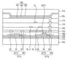
도 8은 본 발명의 일 실시예에 따른 표시 장치의 단면도이다.8 is a cross-sectional view of a display device according to an exemplary embodiment.
도 8을 참조하면, 상기 표시 장치는 무기 절연층(150)을 더 포함하고, 쉴딩 전극(SH)이 데이터 라인(DL)과 중첩하는 것을 제외하고 도 6의 표시 장치와 실질적으로 동일하다. 따라서 반복되는 설명은 생략한다.Referring to FIG. 8 , the display device is substantially the same as the display device of FIG. 6 except that an inorganic insulating
상기 표시 장치는 층간 절연층(140)과 제1 절연층(160) 사이에 배치되는 무기 절연층(150)을 더 포함할 수 있다. 상기 무기 절연층(150)은 무기 절연 물질을 포함할 수 있다.The display device may further include an inorganic insulating
상기 쉴딩 전극(SH)은 제1 연결 라인(CL1) 및 데이터 라인(DL)과 중첩할 수 있다. 이에 따라, 상기 쉴딩 전극(SH)이 상기 제1 연결 라인(CL1)뿐 아니라 상기 데이터 라인(DL)도 쉴딩(shielding)하여 다른 화소 구조 간의 커플링 커패시터 형성을 방지할 수 있다.The shielding electrode SH may overlap the first connection line CL1 and the data line DL. Accordingly, the shielding electrode SH shields not only the first connection line CL1 but also the data line DL, thereby preventing formation of a coupling capacitor between different pixel structures.
도 9는 본 발명의 일 실시예에 따른 표시 장치의 좌측 하단 부분의 확대도이다. 도 10은 도 9의 표시 장치의 데이터 라인 및 연결 라인의 연결 관계를 설명하기 위한 도면이다.9 is an enlarged view of a lower left portion of a display device according to an exemplary embodiment. FIG. 10 is a diagram for explaining a connection relationship between data lines and connection lines of the display device of FIG. 9 .
도 1, 9 및 도 10을 참조하면, 상기 표시 장치는 연결 라인과 데이터 라인이 연결되는 연결 콘택홀이 주변 영역이 아닌 표시 영역에 배치되는 점과, 이에 따라 데이터 스파이더 라인에 전기적으로 연결되는 데이터 라인들이 순차적으로 배치된다는 점을 제외하면, 도 4 및 5의 표시 장치와 실질적으로 동일하다. 따라서 반복되는 설명은 생략한다.1, 9, and 10, the display device has a connection contact hole through which a connection line and a data line are connected is disposed in the display area instead of the peripheral area, and thus data electrically connected to the data spider line. Except for the fact that the lines are arranged sequentially, it is substantially the same as the display device of FIGS. 4 and 5 . Therefore, repeated descriptions are omitted.
제1 연결 라인(CL1)은 표시 영역(AA) 내에 배치되는 제1 연결 콘택홀(CCNT1)을 통해 제1 데이터 라인(DL1)과 연결될 수 있다. 상기 제1 연결 라인(CL1)은 제1 방향(D1)으로 연장되는 부분(CL1b) 및 제1 방향(D1)과 수직한 제2 방향(D2)으로 연장되는 부분(CL1c)을 포함할 수 있다.The first connection line CL1 may be connected to the first data line DL1 through the first connection contact hole CCNT1 disposed in the display area AA. The first connection line CL1 may include a portion CL1b extending in a first direction D1 and a portion CL1c extending in a second direction D2 perpendicular to the first direction D1. .
도 10을 다시 참조하면, 상기 데이터 라인들(DATA LINE)은 상기 데이터 스파이더 라인(DATA SPIDER LINE)의 배열 순서와 동일한 순서로 서로 전기적으로 연결될 수 있다. 이에 따라 도 4 및 5의 표시 장치와 달리, 상기 데이터 스파이더 라인에 연결되는 데이터 구동 칩의 출력 신호 순서를 변경할 필요가 없으며, 일반적으로 설계된 데이터 구동 칩을 그대로 사용할 수 있다.Referring back to FIG. 10 , the data lines DATA LINE may be electrically connected to each other in the same order as the arrangement of the DATA SPIDER LINE. Accordingly, unlike the display devices of FIGS. 4 and 5 , there is no need to change the order of output signals of the data driving chip connected to the data spider line, and the generally designed data driving chip can be used as it is.
도 11은 본 발명의 일 실시예에 따른 표시 장치의 데이터 라인 및 연결 라인의 연결 관계를 설명하기 위한 도면이다.11 is a diagram for explaining a connection relationship between a data line and a connection line of a display device according to an exemplary embodiment.
도 11을 참조하면, 상기 표시 장치는 2개 데이터 라인(DATA LINE)당 하나의 연결 라인(CONNECTING LINE)이 연결되는 것을 제외하고, 도 4 및 5의 표시 장치와 실질적으로 동일할 수 있다. 상기 2개의 데이터 라인 당 하나의 연결 라인 및 하나의 데이터 스파이더 라인(DATA SPIDER LINE)이 대응하므로, 예를 들면, 디멀티플렉서 (demultiplexer, demux) 구조가 적용된 표시 장치 등이 해당될 수 있다. 이에 따라 표시 영역에 배치되는 연결 라인의 개수를 줄일 수 있다.Referring to FIG. 11 , the display device may be substantially the same as the display devices of FIGS. 4 and 5 except that one connecting line is connected to each two data lines. Since one connection line and one data spider line correspond to each of the two data lines, for example, a display device to which a demultiplexer (demux) structure is applied may correspond. Accordingly, the number of connection lines disposed in the display area may be reduced.
도 12는 본 발명의 일 실시예에 따른 표시 장치의 단면도이다. 도 13는 본 발명의 일 실시예에 따른 표시 장치의 단면도이다. 도 14는 본 발명의 일 실시예에 따른 표시 장치의 단면도이다. 도 15는 본 발명의 일 실시예에 따른 표시 장치의 단면도이다.12 is a cross-sectional view of a display device according to an exemplary embodiment. 13 is a cross-sectional view of a display device according to an exemplary embodiment. 14 is a cross-sectional view of a display device according to an exemplary embodiment. 15 is a cross-sectional view of a display device according to an exemplary embodiment.
도 12 내지 15에는 연결 라인(CL), 데이터 라인(DL_E,DL_0), 및 쉴딩 전극(SH)의 위치가 다양하게 변경된 표시 장치의 실시예들이 도시되어 있다. 여기서, 상기 데이터 라인은 짝수번째 데이터 라인(DL_E) 및 홀수 번째 데이터 라인(DL_0)를 포함하고 있으며, 하나의 화소에 두개의 데이터 라인이 대응되는 TDL(two data line) 구조, 디멀티플렉서 (demultiplexer, demux) 구조 등이 적용된 표시 장치 등이 해당될 수 있다.12 to 15 illustrate exemplary embodiments of display devices in which positions of connection lines CL, data lines DL_E and DL_0, and shielding electrodes SH are variously changed. Here, the data lines include an even-numbered data line DL_E and an odd-numbered data line DL_0, and a two data line (TDL) structure in which two data lines correspond to one pixel, a demultiplexer (demux) ) may correspond to a display device to which a structure or the like is applied.
도 16은 본 발명의 실시예들에 따른 전자 기기를 나타내는 블록도이고, 도 17a는 도 16의 전자 기기가 텔레비전으로 구현된 일 예를 나타내는 도면이며, 도 17b는 도 16의 전자 기기가 스마트폰으로 구현된 일 예를 나타내는 도면이다.16 is a block diagram illustrating an electronic device according to embodiments of the present invention, FIG. 17A is a diagram illustrating an example in which the electronic device of FIG. 16 is implemented as a television, and FIG. 17B is a diagram showing the electronic device of FIG. 16 as a smartphone. It is a drawing showing an example implemented as
도 16 내지 도 17b를 참조하면, 전자 기기(500)는 프로세서(510), 메모리 장치(520), 스토리지 장치(530), 입출력 장치(540), 파워 서플라이(550) 및 표시 장치(560)를 포함할 수 있다. 이 때, 상기 표시 장치(560)는 도 1의 표시 장치에 상응할 수 있다. 상기 전자 기기(500)는 비디오 카드, 사운드 카드, 메모리 카드, USB 장치 등과 통신하거나, 또는 다른 시스템들과 통신할 수 있는 여러 포트(port)들을 더 포함할 수 있다. 일 실시예에서, 도 11a에 도시된 바와 같이, 상기 전자 기기(500)는 텔레비전으로 구현될 수 있다. 다른 실시예에서, 도 11b에 도시된 바와 같이, 상기 전자 기기(500)는 스마트폰으로 구현될 수 있다. 다만, 이것은 예시적인 것으로서 상기 전자 기기(500)는 그에 한정되지 않는다. 예를 들어, 상기 전자 기기(500)는 휴대폰, 비디오폰, 스마트패드(smart pad), 스마트 워치(smart watch), 태블릿(tablet) PC, 차량용 네비게이션, 컴퓨터 모니터, 노트북, 헤드 마운트 디스플레이(head mounted display; HMD) 등으로 구현될 수도 있다.16 to 17B, an
상기 프로세서(510)는 특정 계산들 또는 태스크(task)들을 수행할 수 있다. 실시예에 따라, 상기 프로세서(510)는 마이크로프로세서(micro processor), 중앙 처리 유닛(Central Processing Unit; CPU), 어플리케이션 프로세서(Application Processor; AP) 등일 수 있다. 상기 프로세서(510)는 어드레스 버스(address bus), 제어 버스(control bus) 및 데이터 버스(data bus) 등을 통해 다른 구성 요소들에 연결될 수 있다. 실시예에 따라, 상기 프로세서(510)는 주변 구성 요소 상호 연결(Peripheral Component Interconnect; PCI) 버스와 같은 확장 버스에도 연결될 수 있다. 상기 메모리 장치(520)는 상기 전자 기기(500)의 동작에 필요한 데이터들을 저장할 수 있다. 예를 들어, 상기 메모리 장치(520)는 이피롬(Erasable Programmable Read-Only Memory; EPROM) 장치, 이이피롬(Electrically Erasable Programmable Read-Only Memory; EEPROM) 장치, 플래시 메모리 장치(flash memory device), 피램(Phase Change Random Access Memory; PRAM) 장치, 알램(Resistance Random Access Memory; RRAM) 장치, 엔에프지엠(Nano Floating Gate Memory; NFGM) 장치, 폴리머램(Polymer Random Access Memory; PoRAM) 장치, 엠램(Magnetic Random Access Memory; MRAM), 에프램(Ferroelectric Random Access Memory; FRAM) 장치 등과 같은 비휘발성 메모리 장치 및/또는 디램(Dynamic Random Access Memory; DRAM) 장치, 에스램(Static Random Access Memory; SRAM) 장치, 모바일 DRAM 장치 등과 같은 휘발성 메모리 장치를 포함할 수 있다. 상기 스토리지 장치(530)는 솔리드 스테이트 드라이브(Solid State Drive; SSD), 하드 디스크 드라이브(Hard Disk Drive; HDD), 씨디롬(CD-ROM) 등을 포함할 수 있다. 상기 입출력 장치(540)는 키보드, 키패드, 터치패드, 터치스크린, 마우스 등과 같은 입력 수단 및 스피커, 프린터 등과 같은 출력 수단을 포함할 수 있다. 상기 파워 서플라이(550)는 상기 전자 기기(500)의 동작에 필요한 파워를 공급할 수 있다.The
상기 표시 장치(560)는 상기 버스들 또는 다른 통신 링크를 통해서 다른 구성 요소들에 연결될 수 있다. 실시예에 따라, 상기 표시 장치(560)는 상기 입출력 장치(540)에 포함될 수도 있다. 상술한 바와 같이, 상기 표시 장치(560)는 표시 영역의 가장자리 일부에 대한 데이터 스파이더 라인이 연결라인을 통해 데이터 라인과 연결되는 구조를 가짐으로써, 표시 장치의 가장자리 L-cut 부(도 4등 참조)의 비표시 영역인 베젤 폭을 줄일 수 있다. 또한 쉴딩 전극에 의해, 상기 연결 라인이 다른 신호 배선들로부터 차폐될 수 있다. 다만, 이에 대해서는 상술한 바 있으므로, 그에 대한 중복되는 설명은 생략하기로 한다.The
본 발명은 유기 발광 표시 장치 및 이를 포함하는 다양한 전자 기기들에 적용될 수 있다. 예를 들어, 본 발명은 휴대폰, 스마트폰, 비디오폰, 스마트패드, 스마트 워치, 태블릿 PC, 차량용 네비게이션, 텔레비전, 컴퓨터 모니터, 노트북, 헤드 마운트 디스플레이 등에 적용될 수 있다.The present invention can be applied to an organic light emitting display device and various electronic devices including the same. For example, the present invention can be applied to mobile phones, smart phones, video phones, smart pads, smart watches, tablet PCs, car navigation systems, televisions, computer monitors, laptop computers, head mounted displays, and the like.
이상에서는 본 발명의 예시적인 실시예들을 참조하여 설명하였지만, 해당 기술 분야에서 통상의 지식을 가진 자라면 하기의 특허 청구의 범위에 기재된 본 발명의 사상 및 영역으로부터 벗어나지 않는 범위 내에서 본 발명을 다양하게 수정 및 변경시킬 수 있음을 이해할 수 있을 것이다.Although the above has been described with reference to exemplary embodiments of the present invention, those skilled in the art can make various modifications to the present invention within the scope not departing from the spirit and scope of the present invention described in the claims below. It will be understood that it can be modified and changed accordingly.
100: 베이스 기판 110: 버퍼층
120: 제1 게이트 절연층130: 제2 게이트 절연층
140: 층간 절연층160: 제1 절연층
170: 제2 절연층180: 발광 구조물
TFT: 박막 트랜지스터CL: 연결라인
DL: 데이터 라인100: base substrate 110: buffer layer
120: first gate insulating layer 130: second gate insulating layer
140: interlayer insulating layer 160: first insulating layer
170: second insulating layer 180: light emitting structure
TFT: thin film transistor CL: connection line
DL: data line
Claims (20)
Translated fromKorean베이스 기판;
상기 베이스 기판 상에 상기 표시 영역에 배치되는 제1 데이터 라인;
상기 베이스 기판 상에 적어도 일부가 상기 표시 영역에 배치되고, 연결 콘택홀을 통해 상기 제1 데이터 라인과 전기적으로 연결되는 제1 연결 라인;
상기 주변 영역에 배치되는 데이터 패드; 및
상기 데이터 패드와 상기 표시 영역 사이의 상기 주변 영역에 배치되어, 상기 제1 연결 라인 및 상기 데이터 패드와 전기적으로 연결되는 제1 데이터 스파이더 라인을 포함하는 것을 특징으로 하는 표시 장치.A display device including a display area where an image is displayed and a peripheral area that is a non-display area,
base substrate;
a first data line disposed in the display area on the base substrate;
a first connection line disposed on the base substrate at least partially in the display area and electrically connected to the first data line through a connection contact hole;
a data pad disposed in the peripheral area; and
and a first data spider line disposed in the peripheral area between the data pad and the display area and electrically connected to the first connection line and the data pad.
상기 베이스 기판은 가요성 기판이고,
상기 표시 장치는 상기 데이터 패드와 상기 표시 영역 사이에 배치되어 상기 표시 영역의 가장자리와 평행한 제1 방향으로 연장되고, 벤딩 영역을 더 포함하고,
상기 제1 데이터 스파이더 라인은 상기 벤딩 영역과 상기 표시 영역 사이의 상기 주변 영역에 배치되고, 상기 제1 방향에 수직한 제2 방향으로 일직선으로 연장되는 것을 특징으로 하는 표시 장치.According to claim 1,
The base substrate is a flexible substrate,
the display device is disposed between the data pad and the display area, extends in a first direction parallel to an edge of the display area, and further includes a bending area;
The first data spider line is disposed in the peripheral area between the bending area and the display area and extends in a straight line in a second direction perpendicular to the first direction.
상기 벤딩 영역의 상기 제1 방향으로의 길이는 상기 표시 영역의 상기 제1 방향으로의 길이 보다 작은 것을 특징으로 하는 표시 장치.According to claim 2,
The display device of claim 1 , wherein a length of the bending area in the first direction is smaller than a length of the display area in the first direction.
상기 베이스 기판 상에 상기 표시 영역에 배치되고 상기 제1 데이터 라인과 평행하게 연장되는 복수의 데이터 라인들; 및
상기 데이터 패드와 상기 표시 영역 사이의 상기 주변 영역에 배치되어, 각각의 상기 복수의 데이터 라인들과 전기적으로 연결되고, 상기 제1 데이터 스파이더 라인과 평행하게 연장되는 복수의 데이터 스파이더 라인을 더 포함하고,
상기 제1 데이터 스파이더 라인 및 상기 복수의 데이터 스파이더 라인들은 모두 상기 제2 방향으로 연장되는 것을 특징으로 하는 표시 장치.According to claim 2,
a plurality of data lines disposed in the display area on the base substrate and extending parallel to the first data line; and
a plurality of data spider lines disposed in the peripheral area between the data pad and the display area, electrically connected to each of the plurality of data lines, and extending in parallel with the first data spider line; ,
The display device of claim 1 , wherein both the first data spider line and the plurality of data spider lines extend in the second direction.
상기 연결 콘택홀은 상기 주변 영역에 배치되는 것을 특징으로 하는 표시 장치.According to claim 1,
The display device of claim 1 , wherein the connection contact hole is disposed in the peripheral area.
상기 제1 데이터 라인은 제1 방향과 수직한 제2 방향으로 연장되고,
상기 제1 연결 라인은 상기 제2 방향으로 연장되는 제1 부분, 상기 제1 부분과 연결되고 상기 제1 방향으로 연장되는 제2 부분 및 상기 제1 부분과 평행한 제3 부분을 포함하는 것을 특징으로 하는 표시 장치.According to claim 5,
The first data line extends in a second direction perpendicular to the first direction;
The first connection line includes a first portion extending in the second direction, a second portion connected to the first portion and extending in the first direction, and a third portion parallel to the first portion. display device to be.
상기 연결 콘택홀은 상기 표시 영역 내에 배치되는 것을 특징으로 하는 표시 장치.According to claim 1,
The display device of claim 1 , wherein the connection contact hole is disposed within the display area.
상기 베이스 기판 상에 상기 표시 영역에 배치되고 상기 제1 데이터 라인과 인접하여 배치되는 제2 데이터 라인을 더 포함하고,
상기 제1 및 제2 데이터 라인은 상기 주변 영역에서 서로 연결되고, 상기 제1 연결라인과 전기적으로 연결되는 것을 특징으로 하는 표시 장치.According to claim 1,
a second data line disposed in the display area on the base substrate and disposed adjacent to the first data line;
The display device of claim 1 , wherein the first and second data lines are connected to each other in the peripheral area and electrically connected to the first connection line.
상기 제1 데이터 라인과 평행하고, 상기 표시 영역의 가장자리와 평행한 제1 방향을 따라 순차적으로 배열되는 제(n-1)번째 데이터 라인, 제(n) 번째 데이터 라인 및 제(n+1) 번째 데이터 라인을 더 포함하고,
상기 데이터 패드에는 상기 제1 방향을 따라, 상기 제(n) 번째 데이터 라인과 전기적으로 연결되는 제(n) 패드, 상기 제(n-1) 번째 데이터 라인과 전기적으로 연결되는 제(n-1) 패드, 상기 제(n+1) 번째 데이터 라인과 전기적으로 연결되는 제(n+1) 패드, 및 상기 제1 데이터 라인과 전기적으로 연결되는 제n 패드가 배치되는 것을 특징으로 하는 표시 장치.According to claim 1,
The (n−1)th data line, the (n)th data line, and the (n+1)th data line sequentially arranged along a first direction parallel to the first data line and parallel to the edge of the display area. Further including a second data line,
The data pad includes the (n)th pad electrically connected to the (n)th data line and the (n−1th) electrically connected to the (n−1)th data line along the first direction. ) pad, a (n+1)th pad electrically connected to the (n+1)th data line, and an nth pad electrically connected to the first data line.
상기 베이스 기판 상에 적어도 일부가 상기 표시 영역에 배치되고, 연결 콘택홀을 통해 상기 제(n-1)번째 데이터 라인과 전기적으로 연결되는 제(n-1)번째 연결 라인;
상기 데이터 패드와 상기 표시 영역 사이의 상기 주변 영역에 배치되어, 상기 제(n-1)번째 연결 라인 및 상기 데이터 패드와 전기적으로 연결되는 제(n-1)번째 데이터 스파이더 라인;
상기 데이터 패드와 상기 표시 영역 사이의 상기 주변 영역에 배치되어, 상기 제(n)번째 데이터 라인 및 상기 데이터 패드와 전기적으로 연결되는 제(n)번째 데이터 스파이더 라인; 및
상기 데이터 패드와 상기 표시 영역 사이의 상기 주변 영역에 배치되어, 상기 제(n+1)번째 데이터 라인 및 상기 데이터 패드와 전기적으로 연결되는 제(n+1)번째 데이터 스파이더 라인을 더 포함하는 것을 특징으로 하는 표시 장치.According to claim 9,
a (n-1)th connection line, at least partially disposed on the base substrate, in the display area and electrically connected to the (n-1)th data line through a connection contact hole;
a (n-1)th data spider line disposed in the peripheral area between the data pad and the display area and electrically connected to the (n-1)th connection line and the data pad;
a (n) th data spider line disposed in the peripheral area between the data pad and the display area and electrically connected to the (n) th data line and the data pad; and
and an (n+1)th data spider line disposed in the peripheral area between the data pad and the display area and electrically connected to the (n+1)th data line and the data pad. characterized display device.
상기 주변 영역은 상기 표시 영역의 좌측에 인접하는 좌측 주변 영역, 상기 표시 영역의 우측에 인접하는 우측 주변영역, 상기 표시 영역의 상측에 인접하는 상측 주변 영역 및 상기 표시 영역의 하측에 인접하는 하측 주변 영역을 포함하고,
상기 데이터 패드는 하측 주변 영역에 배치되는 것을 특징으로 하는 표시 장치.According to claim 1,
The peripheral area includes a left peripheral area adjacent to the left side of the display area, a right peripheral area adjacent to the right side of the display area, an upper peripheral area adjacent to the upper side of the display area, and a lower peripheral area adjacent to the lower side of the display area. contain the area,
The display device according to claim 1 , wherein the data pad is disposed in a lower peripheral area.
상기 제1 데이터 라인과 전기적으로 연결되는 박막 트랜지스터;
상기 박막 트랜지스터와 전기적으로 연결되는 제1 전극;
상기 제1 전극 상에 배치되는 제2 전극; 및
상기 제1 전극 및 상기 제2 전극 사이에 배치되는 발광층을 더 포함하는 것을 특징으로 하는 표시 장치.According to claim 1,
a thin film transistor electrically connected to the first data line;
a first electrode electrically connected to the thin film transistor;
a second electrode disposed on the first electrode; and
The display device further comprising a light emitting layer disposed between the first electrode and the second electrode.
상기 제1 연결 라인과 중첩하게 배치되는 쉴딩 전극을 더 포함하고,
상기 쉴딩 전극에는 제1 전원(ELVDD) 또는 제2 전원(ELVSS)이 인가되는 것을 특징으로 하는 표시 장치.According to claim 12,
Further comprising a shielding electrode disposed to overlap the first connection line,
A display device characterized in that a first power source (ELVDD) or a second power source (ELVSS) is applied to the shielding electrode.
상기 제1 연결 라인과 상기 제1 데이터 스파이더 라인은 상기 주변 영역에 형성되는 스파이더 콘택홀을 통해 서로 연결되는 것을 특징으로 하는 표시 장치.According to claim 1,
The display device of claim 1 , wherein the first connection line and the first data spider line are connected to each other through a spider contact hole formed in the peripheral area.
베이스 기판;
상기 베이스 기판 상에 배치되는 박막 트랜지스터;
상기 박막 트랜지스터와 전기적으로 연결되는 제1 데이터 라인;
상기 베이스 기판 상에 적어도 일부가 상기 표시 영역에 배치되고, 상기 제1 데이터 라인과 전기적으로 연결되는 제1 연결 라인;
상기 제1 데이터 라인과 상기 제1 연결 라인 사이에 배치되고, 상기 제1 데이터 라인과 상기 제1 연결 라인이 서로 연결되는 제1 연결 콘택홀이 형성된 제1 절연층; 및
상기 제1 연결 라인과 중첩하는 쉴딩 전극을 포함하는 표시 장치.A display device including a display area where an image is displayed and a peripheral area that is a non-display area,
base substrate;
a thin film transistor disposed on the base substrate;
a first data line electrically connected to the thin film transistor;
a first connection line disposed on the base substrate in at least a portion of the display area and electrically connected to the first data line;
a first insulating layer disposed between the first data line and the first connection line and having a first connection contact hole through which the first data line and the first connection line are connected; and
A display device including a shielding electrode overlapping the first connection line.
상기 박막 트랜지스터는 상기 베이스 기판 상에 배치되는 액티브 패턴 및 상기 액티브 패턴과 중첩하는 게이트 전극을 포함하고,
상기 게이트 전극과 동일한 층에 형성되고, 상기 제1 연결 라인과 전기적으로 연결되는 제1 데이터 스파이더 라인을 더 포함하는 것을 특징으로 하는 표시 장치.According to claim 15,
The thin film transistor includes an active pattern disposed on the base substrate and a gate electrode overlapping the active pattern,
and a first data spider line formed on the same layer as the gate electrode and electrically connected to the first connection line.
상기 쉴딩 전극은 상기 박막 트랜지스터와 상기 제1 연결 라인 사이에 배치되는 것을 특징으로 하는 표시 장치.According to claim 15,
The shielding electrode is disposed between the thin film transistor and the first connection line.
상기 쉴딩 전극은 상기 제1 데이터 라인과 중첩하는 것을 특징으로 하는 표시 장치.According to claim 15,
The shielding electrode overlaps the first data line.
상기 제1 데이터 라인과 인접하여 평행하게 연장되는 제2 데이터 라인을 더 포함하고,
상기 제1 데이터 라인 및 상기 제2 데이터 라인은 상기 제1 연결 라인에 전기적으로 연결되고,
상기 쉴딩 전극은 상기 제1 데이터 라인 및 상기 제2 데이터 라인과 중첩하는 것을 특징으로 하는 표시 장치.According to claim 15,
A second data line extending parallel to and adjacent to the first data line;
The first data line and the second data line are electrically connected to the first connection line,
The shielding electrode overlaps the first data line and the second data line.
베이스 기판;
상기 베이스 기판 상에 배치되는 제1 데이터 라인 및 제2 데이터 라인;
상기 베이스 기판 상에 적어도 일부가 상기 표시 영역에 배치되고, 상기 제1 데이터 라인과 콘택홀을 통해 연결되는 제1 연결 라인;
제1 연결라인과 콘택홀을 통해 연결되는 제1 스파이더 라인;
상기 제2 데이터 라인과 콘택홀을 통해 연결되는 제2 스파이더 라인; 및
상기 제1 스파이더 라인 및 상기 제2 스파이더 라인과 전기적으로 연결되고 데이터 구동칩이 연결되는 데이터 패드를 포함하는 표시 장치.
A display device including a display area where an image is displayed and a peripheral area that is a non-display area,
base substrate;
a first data line and a second data line disposed on the base substrate;
a first connection line disposed on the base substrate at least partially in the display area and connected to the first data line through a contact hole;
a first spider line connected to the first connection line through a contact hole;
a second spider line connected to the second data line through a contact hole; and
and a data pad electrically connected to the first spider line and the second spider line and to which a data driving chip is connected.
Priority Applications (9)
| Application Number | Priority Date | Filing Date | Title |
|---|---|---|---|
| KR1020180083825AKR102528500B1 (en) | 2018-07-19 | 2018-07-19 | Display apparatus |
| CN202510129119.7ACN119907550A (en) | 2018-07-19 | 2019-07-12 | Display Devices |
| EP19837592.5AEP3813137B1 (en) | 2018-07-19 | 2019-07-12 | Display device |
| PCT/KR2019/008669WO2020017835A1 (en) | 2018-07-19 | 2019-07-12 | Display device |
| CN201980048341.7ACN112840475B (en) | 2018-07-19 | 2019-07-12 | Display apparatus |
| US17/261,527US12035595B2 (en) | 2018-07-19 | 2019-07-12 | Display apparatus |
| JP2021502997AJP7553428B2 (en) | 2018-07-19 | 2019-07-12 | Display device |
| KR1020230055638AKR102632740B1 (en) | 2018-07-19 | 2023-04-27 | Display apparatus |
| US18/766,517US20240365621A1 (en) | 2018-07-19 | 2024-07-08 | Display apparatus |
Applications Claiming Priority (1)
| Application Number | Priority Date | Filing Date | Title |
|---|---|---|---|
| KR1020180083825AKR102528500B1 (en) | 2018-07-19 | 2018-07-19 | Display apparatus |
Related Child Applications (1)
| Application Number | Title | Priority Date | Filing Date |
|---|---|---|---|
| KR1020230055638ADivisionKR102632740B1 (en) | 2018-07-19 | 2023-04-27 | Display apparatus |
Publications (2)
| Publication Number | Publication Date |
|---|---|
| KR20200010697A KR20200010697A (en) | 2020-01-31 |
| KR102528500B1true KR102528500B1 (en) | 2023-05-04 |
Family
ID=69164613
Family Applications (2)
| Application Number | Title | Priority Date | Filing Date |
|---|---|---|---|
| KR1020180083825AActiveKR102528500B1 (en) | 2018-07-19 | 2018-07-19 | Display apparatus |
| KR1020230055638AActiveKR102632740B1 (en) | 2018-07-19 | 2023-04-27 | Display apparatus |
Family Applications After (1)
| Application Number | Title | Priority Date | Filing Date |
|---|---|---|---|
| KR1020230055638AActiveKR102632740B1 (en) | 2018-07-19 | 2023-04-27 | Display apparatus |
Country Status (6)
| Country | Link |
|---|---|
| US (2) | US12035595B2 (en) |
| EP (1) | EP3813137B1 (en) |
| JP (1) | JP7553428B2 (en) |
| KR (2) | KR102528500B1 (en) |
| CN (2) | CN112840475B (en) |
| WO (1) | WO2020017835A1 (en) |
Cited By (1)
| Publication number | Priority date | Publication date | Assignee | Title |
|---|---|---|---|---|
| WO2024248362A1 (en)* | 2023-05-26 | 2024-12-05 | 삼성디스플레이주식회사 | Display apparatus |
Families Citing this family (28)
| Publication number | Priority date | Publication date | Assignee | Title |
|---|---|---|---|---|
| KR102555841B1 (en)* | 2018-10-30 | 2023-07-17 | 삼성디스플레이 주식회사 | Display apparatus |
| KR102798966B1 (en) | 2019-04-01 | 2025-04-24 | 삼성디스플레이 주식회사 | Electronic apparatus |
| KR102772543B1 (en)* | 2019-06-13 | 2025-02-26 | 삼성디스플레이 주식회사 | Display apparatus |
| KR102845509B1 (en)* | 2019-08-07 | 2025-08-12 | 삼성디스플레이 주식회사 | Display apparatus and the manufacturing method thereof |
| KR102866752B1 (en) | 2019-09-05 | 2025-09-30 | 삼성디스플레이 주식회사 | Display Apparatus |
| KR102779180B1 (en) | 2019-09-16 | 2025-03-10 | 삼성디스플레이 주식회사 | Display device |
| KR102776380B1 (en) | 2019-09-27 | 2025-03-10 | 삼성디스플레이 주식회사 | Display apparatus |
| KR102849776B1 (en) | 2020-03-06 | 2025-08-26 | 삼성디스플레이 주식회사 | Display device |
| KR102733852B1 (en)* | 2020-04-29 | 2024-11-27 | 삼성디스플레이 주식회사 | Organic light-emitting display and method for manufacturing the same |
| CN113906568B (en)* | 2020-05-07 | 2022-08-19 | 京东方科技集团股份有限公司 | Array substrate and display device |
| KR102827182B1 (en) | 2020-05-29 | 2025-07-02 | 삼성디스플레이 주식회사 | Display apparatus |
| KR20220077323A (en)* | 2020-12-01 | 2022-06-09 | 삼성디스플레이 주식회사 | Display device |
| KR102838156B1 (en)* | 2020-12-23 | 2025-07-24 | 삼성디스플레이 주식회사 | Display device |
| US12274137B2 (en) | 2021-01-29 | 2025-04-08 | Boe Technology Group Co., Ltd. | Display substrate and display device with lead lines |
| KR20220144451A (en) | 2021-04-19 | 2022-10-27 | 삼성디스플레이 주식회사 | Display apparatus |
| KR20230016764A (en) | 2021-07-26 | 2023-02-03 | 삼성디스플레이 주식회사 | Display apparatus |
| KR20230067750A (en)* | 2021-11-08 | 2023-05-17 | 삼성디스플레이 주식회사 | Display panel and electronic apparatus including the same |
| WO2023201554A1 (en)* | 2022-04-20 | 2023-10-26 | 京东方科技集团股份有限公司 | Display panel and display apparatus |
| CN115207073B (en)* | 2022-04-25 | 2023-10-24 | 京东方科技集团股份有限公司 | Display substrate and display device |
| TWI822016B (en)* | 2022-04-28 | 2023-11-11 | 元太科技工業股份有限公司 | Display device |
| US20230351934A1 (en) | 2022-04-28 | 2023-11-02 | E Ink Holdings Inc. | Narrow border reflective display device |
| US20230397462A1 (en)* | 2022-06-03 | 2023-12-07 | Samsung Display Co., Ltd. | Display device |
| CN115132760B (en)* | 2022-06-30 | 2025-10-03 | 武汉华星光电半导体显示技术有限公司 | Display panel and display device |
| US20240119889A1 (en)* | 2022-10-07 | 2024-04-11 | Samsung Display Co., Ltd. | Display device |
| KR20240092973A (en)* | 2022-12-15 | 2024-06-24 | 엘지디스플레이 주식회사 | Display device and display panel |
| KR20240120773A (en)* | 2023-01-31 | 2024-08-08 | 엘지디스플레이 주식회사 | Display panel and display apparatus |
| KR20250050157A (en)* | 2023-10-05 | 2025-04-15 | 삼성디스플레이 주식회사 | Display device |
| KR20250104351A (en)* | 2023-12-29 | 2025-07-08 | 엘지디스플레이 주식회사 | Display apparatus |
Family Cites Families (17)
| Publication number | Priority date | Publication date | Assignee | Title |
|---|---|---|---|---|
| JP2003288044A (en)* | 2002-03-28 | 2003-10-10 | Tdk Corp | Display device |
| KR20060001702A (en)* | 2004-06-30 | 2006-01-06 | 엘지.필립스 엘시디 주식회사 | Liquid crystal display device and method for manufacturing same for preventing corrosion |
| KR100603836B1 (en)* | 2004-11-30 | 2006-07-24 | 엘지.필립스 엘시디 주식회사 | Organic electroluminescent device and manufacturing method thereof |
| KR100721949B1 (en)* | 2005-09-16 | 2007-05-25 | 삼성에스디아이 주식회사 | Organic electroluminescent display |
| KR101433109B1 (en)* | 2007-10-16 | 2014-08-26 | 엘지디스플레이 주식회사 | An Array Substrate of Liquid Crystal Display Device and the method for fabricating thereof |
| KR20100075058A (en)* | 2008-12-24 | 2010-07-02 | 삼성전자주식회사 | Thin film transistor array substrate and method thereof |
| KR101602332B1 (en)* | 2009-12-01 | 2016-03-11 | 엘지디스플레이 주식회사 | Liquid crystal display device and method of fabricating the same |
| TWI790673B (en) | 2013-03-07 | 2023-01-21 | 日商半導體能源研究所股份有限公司 | Electronic device |
| US9430180B2 (en) | 2013-11-15 | 2016-08-30 | Semiconductor Energy Laboratory Co., Ltd | Display panel and electronic device |
| WO2016140281A1 (en)* | 2015-03-02 | 2016-09-09 | シャープ株式会社 | Active matrix substrate and display device provided therewith |
| KR102481377B1 (en) | 2015-08-13 | 2022-12-27 | 삼성디스플레이 주식회사 | Array substrate |
| KR102427312B1 (en) | 2015-11-27 | 2022-08-01 | 엘지디스플레이 주식회사 | Organic light-emitting display panel and organic light-emitting display device |
| KR20180030325A (en) | 2016-09-13 | 2018-03-22 | 삼성디스플레이 주식회사 | Display device |
| US20190278145A1 (en) | 2016-09-27 | 2019-09-12 | Sharp Kabushiki Kaisha | Display panel |
| KR102743728B1 (en)* | 2016-11-08 | 2024-12-19 | 삼성디스플레이 주식회사 | Display device |
| KR102594020B1 (en) | 2016-12-07 | 2023-10-27 | 삼성디스플레이 주식회사 | Display device |
| KR102731256B1 (en) | 2016-12-30 | 2024-11-19 | 엘지디스플레이 주식회사 | Display device and method for manufacturing thereof |
- 2018
- 2018-07-19KRKR1020180083825Apatent/KR102528500B1/enactiveActive
- 2019
- 2019-07-12EPEP19837592.5Apatent/EP3813137B1/enactiveActive
- 2019-07-12CNCN201980048341.7Apatent/CN112840475B/enactiveActive
- 2019-07-12USUS17/261,527patent/US12035595B2/enactiveActive
- 2019-07-12JPJP2021502997Apatent/JP7553428B2/enactiveActive
- 2019-07-12WOPCT/KR2019/008669patent/WO2020017835A1/ennot_activeCeased
- 2019-07-12CNCN202510129119.7Apatent/CN119907550A/enactivePending
- 2023
- 2023-04-27KRKR1020230055638Apatent/KR102632740B1/enactiveActive
- 2024
- 2024-07-08USUS18/766,517patent/US20240365621A1/enactivePending
Cited By (1)
| Publication number | Priority date | Publication date | Assignee | Title |
|---|---|---|---|---|
| WO2024248362A1 (en)* | 2023-05-26 | 2024-12-05 | 삼성디스플레이주식회사 | Display apparatus |
Also Published As
| Publication number | Publication date |
|---|---|
| US20240365621A1 (en) | 2024-10-31 |
| US12035595B2 (en) | 2024-07-09 |
| EP3813137A1 (en) | 2021-04-28 |
| CN119907550A (en) | 2025-04-29 |
| CN112840475B (en) | 2025-02-25 |
| EP3813137A4 (en) | 2021-08-11 |
| WO2020017835A1 (en) | 2020-01-23 |
| KR102632740B1 (en) | 2024-02-05 |
| JP2021530746A (en) | 2021-11-11 |
| US20210273035A1 (en) | 2021-09-02 |
| KR20200010697A (en) | 2020-01-31 |
| CN112840475A (en) | 2021-05-25 |
| EP3813137B1 (en) | 2025-07-09 |
| JP7553428B2 (en) | 2024-09-18 |
| KR20230062521A (en) | 2023-05-09 |
Similar Documents
| Publication | Publication Date | Title |
|---|---|---|
| KR102632740B1 (en) | Display apparatus | |
| US11238794B2 (en) | Display apparatus having a notch | |
| KR102804879B1 (en) | Display apparatus | |
| KR102800154B1 (en) | Display apparatus | |
| US11276743B2 (en) | Display apparatus | |
| CN110783345B (en) | Display Devices | |
| US12349564B2 (en) | Display device | |
| US20230141982A1 (en) | Display apparatus | |
| CN111509003B (en) | Display Devices |
Legal Events
| Date | Code | Title | Description |
|---|---|---|---|
| PA0109 | Patent application | Patent event code:PA01091R01D Comment text:Patent Application Patent event date:20180719 | |
| PG1501 | Laying open of application | ||
| A201 | Request for examination | ||
| PA0201 | Request for examination | Patent event code:PA02012R01D Patent event date:20210510 Comment text:Request for Examination of Application Patent event code:PA02011R01I Patent event date:20180719 Comment text:Patent Application | |
| E902 | Notification of reason for refusal | ||
| PE0902 | Notice of grounds for rejection | Comment text:Notification of reason for refusal Patent event date:20220808 Patent event code:PE09021S01D | |
| E701 | Decision to grant or registration of patent right | ||
| PE0701 | Decision of registration | Patent event code:PE07011S01D Comment text:Decision to Grant Registration Patent event date:20230127 | |
| A107 | Divisional application of patent | ||
| GRNT | Written decision to grant | ||
| PA0107 | Divisional application | Comment text:Divisional Application of Patent Patent event date:20230427 Patent event code:PA01071R01D | |
| PR0701 | Registration of establishment | Comment text:Registration of Establishment Patent event date:20230427 Patent event code:PR07011E01D | |
| PR1002 | Payment of registration fee | Payment date:20230428 End annual number:3 Start annual number:1 | |
| PG1601 | Publication of registration |