KR102524890B1 - Automatic filling, inputting and dispensing method of carbon dioxide snow blocks - Google Patents
Automatic filling, inputting and dispensing method of carbon dioxide snow blocksDownload PDFInfo
- Publication number
- KR102524890B1 KR102524890B1KR1020207017508AKR20207017508AKR102524890B1KR 102524890 B1KR102524890 B1KR 102524890B1KR 1020207017508 AKR1020207017508 AKR 1020207017508AKR 20207017508 AKR20207017508 AKR 20207017508AKR 102524890 B1KR102524890 B1KR 102524890B1
- Authority
- KR
- South Korea
- Prior art keywords
- container
- liquid
- controller
- filling
- pressure
- Prior art date
- Legal status (The legal status is an assumption and is not a legal conclusion. Google has not performed a legal analysis and makes no representation as to the accuracy of the status listed.)
- Active
Links
Images


Classifications
- C—CHEMISTRY; METALLURGY
- C01—INORGANIC CHEMISTRY
- C01B—NON-METALLIC ELEMENTS; COMPOUNDS THEREOF; METALLOIDS OR COMPOUNDS THEREOF NOT COVERED BY SUBCLASS C01C
- C01B32/00—Carbon; Compounds thereof
- C01B32/50—Carbon dioxide
- C01B32/55—Solidifying
- A—HUMAN NECESSITIES
- A61—MEDICAL OR VETERINARY SCIENCE; HYGIENE
- A61J—CONTAINERS SPECIALLY ADAPTED FOR MEDICAL OR PHARMACEUTICAL PURPOSES; DEVICES OR METHODS SPECIALLY ADAPTED FOR BRINGING PHARMACEUTICAL PRODUCTS INTO PARTICULAR PHYSICAL OR ADMINISTERING FORMS; DEVICES FOR ADMINISTERING FOOD OR MEDICINES ORALLY; BABY COMFORTERS; DEVICES FOR RECEIVING SPITTLE
- A61J1/00—Containers specially adapted for medical or pharmaceutical purposes
- F—MECHANICAL ENGINEERING; LIGHTING; HEATING; WEAPONS; BLASTING
- F17—STORING OR DISTRIBUTING GASES OR LIQUIDS
- F17C—VESSELS FOR CONTAINING OR STORING COMPRESSED, LIQUEFIED OR SOLIDIFIED GASES; FIXED-CAPACITY GAS-HOLDERS; FILLING VESSELS WITH, OR DISCHARGING FROM VESSELS, COMPRESSED, LIQUEFIED, OR SOLIDIFIED GASES
- F17C6/00—Methods and apparatus for filling vessels not under pressure with liquefied or solidified gases
- F—MECHANICAL ENGINEERING; LIGHTING; HEATING; WEAPONS; BLASTING
- F25—REFRIGERATION OR COOLING; COMBINED HEATING AND REFRIGERATION SYSTEMS; HEAT PUMP SYSTEMS; MANUFACTURE OR STORAGE OF ICE; LIQUEFACTION SOLIDIFICATION OF GASES
- F25D—REFRIGERATORS; COLD ROOMS; ICE-BOXES; COOLING OR FREEZING APPARATUS NOT OTHERWISE PROVIDED FOR
- F25D3/00—Devices using other cold materials; Devices using cold-storage bodies
- F25D3/12—Devices using other cold materials; Devices using cold-storage bodies using solidified gases, e.g. carbon-dioxide snow
- F—MECHANICAL ENGINEERING; LIGHTING; HEATING; WEAPONS; BLASTING
- F25—REFRIGERATION OR COOLING; COMBINED HEATING AND REFRIGERATION SYSTEMS; HEAT PUMP SYSTEMS; MANUFACTURE OR STORAGE OF ICE; LIQUEFACTION SOLIDIFICATION OF GASES
- F25J—LIQUEFACTION, SOLIDIFICATION OR SEPARATION OF GASES OR GASEOUS OR LIQUEFIED GASEOUS MIXTURES BY PRESSURE AND COLD TREATMENT OR BY BRINGING THEM INTO THE SUPERCRITICAL STATE
- F25J1/00—Processes or apparatus for liquefying or solidifying gases or gaseous mixtures
- F25J1/0002—Processes or apparatus for liquefying or solidifying gases or gaseous mixtures characterised by the fluid to be liquefied
- F25J1/0027—Oxides of carbon, e.g. CO2
- F—MECHANICAL ENGINEERING; LIGHTING; HEATING; WEAPONS; BLASTING
- F17—STORING OR DISTRIBUTING GASES OR LIQUIDS
- F17C—VESSELS FOR CONTAINING OR STORING COMPRESSED, LIQUEFIED OR SOLIDIFIED GASES; FIXED-CAPACITY GAS-HOLDERS; FILLING VESSELS WITH, OR DISCHARGING FROM VESSELS, COMPRESSED, LIQUEFIED, OR SOLIDIFIED GASES
- F17C2203/00—Vessel construction, in particular walls or details thereof
- F17C2203/06—Materials for walls or layers thereof; Properties or structures of walls or their materials
- F17C2203/0634—Materials for walls or layers thereof
- F17C2203/0658—Synthetics
- F17C2203/0663—Synthetics in form of fibers or filaments
- F17C2203/0668—Synthetics in form of fibers or filaments axially wound
- F—MECHANICAL ENGINEERING; LIGHTING; HEATING; WEAPONS; BLASTING
- F17—STORING OR DISTRIBUTING GASES OR LIQUIDS
- F17C—VESSELS FOR CONTAINING OR STORING COMPRESSED, LIQUEFIED OR SOLIDIFIED GASES; FIXED-CAPACITY GAS-HOLDERS; FILLING VESSELS WITH, OR DISCHARGING FROM VESSELS, COMPRESSED, LIQUEFIED, OR SOLIDIFIED GASES
- F17C2221/00—Handled fluid, in particular type of fluid
- F17C2221/01—Pure fluids
- F17C2221/013—Carbon dioxide
- F—MECHANICAL ENGINEERING; LIGHTING; HEATING; WEAPONS; BLASTING
- F17—STORING OR DISTRIBUTING GASES OR LIQUIDS
- F17C—VESSELS FOR CONTAINING OR STORING COMPRESSED, LIQUEFIED OR SOLIDIFIED GASES; FIXED-CAPACITY GAS-HOLDERS; FILLING VESSELS WITH, OR DISCHARGING FROM VESSELS, COMPRESSED, LIQUEFIED, OR SOLIDIFIED GASES
- F17C2223/00—Handled fluid before transfer, i.e. state of fluid when stored in the vessel or before transfer from the vessel
- F17C2223/01—Handled fluid before transfer, i.e. state of fluid when stored in the vessel or before transfer from the vessel characterised by the phase
- F17C2223/0107—Single phase
- F17C2223/0138—Single phase solid
- F—MECHANICAL ENGINEERING; LIGHTING; HEATING; WEAPONS; BLASTING
- F17—STORING OR DISTRIBUTING GASES OR LIQUIDS
- F17C—VESSELS FOR CONTAINING OR STORING COMPRESSED, LIQUEFIED OR SOLIDIFIED GASES; FIXED-CAPACITY GAS-HOLDERS; FILLING VESSELS WITH, OR DISCHARGING FROM VESSELS, COMPRESSED, LIQUEFIED, OR SOLIDIFIED GASES
- F17C2223/00—Handled fluid before transfer, i.e. state of fluid when stored in the vessel or before transfer from the vessel
- F17C2223/01—Handled fluid before transfer, i.e. state of fluid when stored in the vessel or before transfer from the vessel characterised by the phase
- F17C2223/0146—Two-phase
- F17C2223/0176—Solids and gas
- F—MECHANICAL ENGINEERING; LIGHTING; HEATING; WEAPONS; BLASTING
- F17—STORING OR DISTRIBUTING GASES OR LIQUIDS
- F17C—VESSELS FOR CONTAINING OR STORING COMPRESSED, LIQUEFIED OR SOLIDIFIED GASES; FIXED-CAPACITY GAS-HOLDERS; FILLING VESSELS WITH, OR DISCHARGING FROM VESSELS, COMPRESSED, LIQUEFIED, OR SOLIDIFIED GASES
- F17C2223/00—Handled fluid before transfer, i.e. state of fluid when stored in the vessel or before transfer from the vessel
- F17C2223/03—Handled fluid before transfer, i.e. state of fluid when stored in the vessel or before transfer from the vessel characterised by the pressure level
- F17C2223/033—Small pressure, e.g. for liquefied gas
- F—MECHANICAL ENGINEERING; LIGHTING; HEATING; WEAPONS; BLASTING
- F17—STORING OR DISTRIBUTING GASES OR LIQUIDS
- F17C—VESSELS FOR CONTAINING OR STORING COMPRESSED, LIQUEFIED OR SOLIDIFIED GASES; FIXED-CAPACITY GAS-HOLDERS; FILLING VESSELS WITH, OR DISCHARGING FROM VESSELS, COMPRESSED, LIQUEFIED, OR SOLIDIFIED GASES
- F17C2225/00—Handled fluid after transfer, i.e. state of fluid after transfer from the vessel
- F17C2225/01—Handled fluid after transfer, i.e. state of fluid after transfer from the vessel characterised by the phase
- F17C2225/0146—Two-phase
- F17C2225/0176—Solids and gas
Landscapes
- Engineering & Computer Science (AREA)
- Chemical & Material Sciences (AREA)
- Chemical Kinetics & Catalysis (AREA)
- Mechanical Engineering (AREA)
- General Engineering & Computer Science (AREA)
- Organic Chemistry (AREA)
- Health & Medical Sciences (AREA)
- Physics & Mathematics (AREA)
- Thermal Sciences (AREA)
- Inorganic Chemistry (AREA)
- Animal Behavior & Ethology (AREA)
- Combustion & Propulsion (AREA)
- Pharmacology & Pharmacy (AREA)
- Life Sciences & Earth Sciences (AREA)
- General Health & Medical Sciences (AREA)
- Veterinary Medicine (AREA)
- Public Health (AREA)
- Filling Of Jars Or Cans And Processes For Cleaning And Sealing Jars (AREA)
- Basic Packing Technique (AREA)
Abstract
Translated fromKoreanDescription
Translated fromKorean본 발명은 분배 스테이션(dispensing station) 내부의 선택된 컨테이너 내에 CO2 스노우 블록(snow block)을 자동으로 생성하기 위한, 또는 투입 스테이션(charging station) 내에 위치될 수 있는 컨테이너 내로의 자동 투입에 의해 CO2 스노우 블록을 자동으로 생성하기 위한 방법에 관한 것이다.The present invention provides for the automatic creation of CO2 snow blocks in selected containers inside a dispensing station, or by automatic dosing into a container that can be located in a charging station. It relates to a method for automatically generating.
약물 개발은 제약 산업에서 지속적인 주요한 시도이다. 약물 개발은 새로운 치료의 안전성 및 효능을 확립하기 위해 임상 시험을 필요로 한다. 오늘날, 미국에서, 단독으로, 다양한 단계에 있는 다수의 진행 중인 임상 시험들이 있다. 각각의 임상 시험은 소정 실험 약물의 투여에 지원한 수백 내지 수천 명의 환자들을 포함할 수 있다. 일반적으로 말하면, 임상 시험의 일부로서, 생물학적 샘플(예컨대, 조직, 소변, 혈액 샘플)들이 임상 현장(clinical site), 예컨대 병원, 대학, 또는 진료실에서 환자들로부터 수집되고, 이어서 분석 실험실로 또는 나중의 분석을 위해 샘플들이 냉동 보관될 수 있는 시설로 운반된다.Drug development is an ongoing major endeavor in the pharmaceutical industry. Drug development requires clinical trials to establish the safety and efficacy of new treatments. Today, in the United States alone, there are a number of ongoing clinical trials at various stages. Each clinical trial may include hundreds to thousands of patients who have volunteered for administration of a given experimental drug. Generally speaking, as part of a clinical trial, biological samples (e.g., tissue, urine, blood samples) are collected from patients at a clinical site, such as a hospital, university, or clinic, and then taken to an analytical laboratory or later. For analysis, samples are transported to a facility where they can be stored frozen.
실험 약물의 안전성 및 효능을 평가하는 능력은 임상 시험 동안에 재현가능하고 신뢰성 있는 결과를 얻는 것을 필요로 한다. 생물학적 샘플은, 예로서 치료소와 실험실 사이의 운반 및 보관 동안에 안정화되고 보존되어야 한다. 오늘날 생물학적 샘플들을 보존하는 통상적인 수단은 고체 이산화탄소(즉, 드라이아이스)의 존재 하에 이들을 냉동 및 보관하는 것이다.The ability to evaluate the safety and efficacy of experimental drugs requires obtaining reproducible and reliable results during clinical trials. Biological samples must be stabilized and preserved during storage and transport between, for example, clinics and laboratories. A common means of preserving biological samples today is to freeze and store them in the presence of solid carbon dioxide (ie, dry ice).
드라이아이스 시스템은 전형적으로, 샘플이 획득되는 임상 현장에서 샘플 및 드라이아이스를 폴리스티렌 상자와 같은 단열 상자 내로 수동으로 로딩하는 것을 포함한다. 단열 상자는 전형적으로 임상 시험을 운영하는 제약 회사 또는 임상 시험 수탁 기관(contract research organization)에 의해 임상 현장에 제공된다. 단열 상자 구성요소들은 조립된 또는 분해된 상태로 제공될 수 있다. 단열 상자의 조립 및 드라이아이스의 로딩은 노동 집약적일 수 있다. 임상 현장에서 드라이아이스의 충분한 공급을 유지하는 것과 연관된 상당한 비용 및 불편함이 또한 있을 수 있다. 부가적으로, 그러한 드라이아이스를 소정의 지속기간 내에 사용하지 못함은 드라이아이스가 그의 냉각 효과를 상실하게 할 수 있다. 또한, 단열 상자는 전형적으로 재사용가능하지 않고 폐기되어야 함으로써, 폐기물을 생성한다.Dry ice systems typically involve manual loading of the sample and dry ice into an insulated box, such as a polystyrene box, at the clinical site where the sample is acquired. Insulated boxes are typically provided to clinical sites by pharmaceutical companies or contract research organizations that run clinical trials. Insulation box components may be provided assembled or disassembled. Assembly of the insulated box and loading of the dry ice can be labor intensive. There may also be significant costs and inconveniences associated with maintaining an adequate supply of dry ice at the clinical site. Additionally, failure to use such dry ice within a predetermined duration may cause the dry ice to lose its cooling effect. Additionally, insulated boxes are typically not reusable and must be discarded, thereby creating waste.
종래의 단열 상자 내에서의 샘플의 운반에 따라 다른 단점이 또한 존재한다. 드라이아이스는 이산화탄소 증기로 승화함에 따라 단열 상자의 내부를 냉각시킨다. 최대 4일 또는 5일의 다양한 지속기간 동안에 저온 내부 온도를 유지할 수 있는 다수의 단열 상자가 입수가능하다. 내부 샘플 공간은 초기 최대 드라이아이스 로딩시 드라이아이스 온도 부근에서 균일하게 있을 수 있지만, 드라이아이스가 승화함에 따라, 내부 샘플 공간 내에서 상당한 온도 구배가 발생하여 잠재적으로는 샘플 품질을 손상시킬 수 있다. 단열 상자는 일반적으로 내부 샘플 공간 내에 충분한 저온이 유지되는 것을 보장하도록 긴급 배송 방법을 통해 운송된다. 그러나, 운송 레인(lane)에서 지연 또는 중단이 발생하면, 샘플은 열화될 수 있다. 운송 동안의 그러한 지연의 결과로서, 환적 동안에 추가의 드라이아이스가 상자 내로 로딩될 필요가 있을 수 있으며, 이는 운송에 대한 비용 및 물류 복잡성을 증가시킨다.Other disadvantages also exist with transport of samples in conventional insulated boxes. Dry ice cools the interior of the insulated box as it sublimates into carbon dioxide vapor. A number of insulated boxes are available that can maintain a cold internal temperature for various durations of up to 4 or 5 days. The internal sample volume may be uniform at around the dry ice temperature during initial maximum dry ice loading, but as the dry ice sublimes, significant temperature gradients may occur within the internal sample volume potentially compromising sample quality. Insulated boxes are usually shipped via expedited shipping methods to ensure that a sufficiently low temperature is maintained within the internal sample space. However, if a delay or disruption occurs in a transport lane, the sample may deteriorate. As a result of such delays during shipping, additional dry ice may need to be loaded into the boxes during transshipment, which increases cost and logistical complexity for shipping.
종래의 드라이아이스 시퍼(shipper)에 대한 하나의 대안은 극저온 액체 질소-기반 증기 베셀(vessel)이다. 극저온 액체 질소-기반 증기 베셀은 증기 상태의 저온 질소를 보유하고 액체 형태의 질소의 존재를 피하기 위해 흡수제를 이용한다. 그러나, 그러한 액체 질소-기반 증기 베셀은 단점을 겪는다. 하나의 단점은 베셀의 제조에 수반되는 시간 및 노동이다. 구체적으로, 사용자는 베셀 내로 액체 질소를 붓고, 흡수제 상으로의 질소의 충분한 흡수가 일어나게 하도록 수 시간을 기다리며, 이어서, 운송 전에 잉여 액체 질소를 따라냄으로써 그러한 베셀을 준비한다. 극저온 액체 질소의 상당한 취급이 필요하며, 그의 사용 전에 액체 질소 시퍼를 준비하는 데 상당한 시간이 요구된다. 또한, 액체 질소-기반 증기 베셀의 사용과 연관된 비용은 대안적인 드라이아이스 베셀보다 상당히 더 높다.One alternative to conventional dry ice shippers is a cryogenic liquid nitrogen-based vapor vessel. Cryogenic liquid nitrogen-based vapor vessels utilize an absorbent to retain the cryogenic nitrogen in a vapor state and avoid the presence of nitrogen in liquid form. However, such liquid nitrogen-based vapor vessels suffer from drawbacks. One drawback is the time and labor involved in manufacturing the vessel. Specifically, the user prepares such a vessel by pouring liquid nitrogen into the vessel, waiting several hours to allow sufficient absorption of the nitrogen onto the absorbent, and then decanting the excess liquid nitrogen prior to shipping. Cryogenic liquid nitrogen requires considerable handling, and considerable time is required to prepare liquid nitrogen sippers prior to their use. Additionally, the costs associated with the use of liquid nitrogen-based vapor vessels are significantly higher than alternative dry ice vessels.
이들 단점을 고려하여, 샘플을 보관 및 운반 동안에 컨테이너 내로 보존하기 위한 개선된 방법에 대한 충족되지 않은 필요성이 존재한다.In view of these drawbacks, there is an unmet need for improved methods for preserving samples into containers during storage and transport.
일 태양에서, 자동 분배 스테이션 내의 컨테이너 내로 이산화탄소(CO2) 스노우 블록을 자동으로 충전하는(filling) 방법은, 액체 CO2의 압력에 대응하는 제1 신호를 제1 설정점(set point)으로서 제어기 내로 수신하는 단계; 생성될 CO2 스노우 블록의 체적을 제2 설정점으로서 제어기 내로 입력하는 단계; 제어기가 제1 설정점 및 제2 설정점에 기초하여 CO2 스노우 블록의 체적을 생성하기 위한 충전 시간을 결정하는 단계; 제어기가 제2 설정점에 대응하는 내부 체적을 갖는 컨테이너를 선택하는 단계 - 상기 컨테이너는 자동 분배 스테이션 내에 위치되고, 상기 자동 분배 스테이션은 상이한 내부 체적들의 2개 이상의 컨테이너들을 포함함 -; 액체 CO2의 상 변화를 방지하기에 충분한 압력 이상으로 충전 도관을 가압하기 위해 기체 CO2를 충전 도관 내로 유동시키는 단계; 제어기가, 충전 도관 내의 압력이 액체 CO2의 상 변화를 방지하기에 충분한 압력 이상이라고 제어기가 결정한 때, 액체 CO2 제어 밸브로 하여금 액체 CO2가 충전 도관을 따라 컨테이너 내로 유동하게 하는 단계; 상기 액체 CO2를 컨테이너 내로 도입하는 단계; 상기 액체 CO2의 적어도 일부분이 상 변화를 겪어 컨테이너 내에서 상기 CO2 스노우 블록 및 오프 가스 CO2로 변환되는 단계; 상기 오프 가스 CO2를 컨테이너로부터, 컨테이너에 영구적으로 부착되거나 제거가능하게 부착된 플레이트를 통해 인출하는 단계 - 상기 플레이트는 오프 가스 CO2에 대해 투과성이고 고체상 CO2에 대해 적어도 부분적으로 불투과성임 -; 컨테이너를 액체 CO2로 충전하는 경과 시간을 측정하고, 경과 시간에 대응하는 제2 신호를 생성하는 단계; 경과 시간에 대응하는 제2 신호를 제어기에 전송하는 단계; 제어기가, (i) 경과 시간이 충전 시간 미만일 때, 오버라이드(override)의 부재 하에, 상기 액체 CO2가 컨테이너 내로 계속 유동하게 하고, (ii) 경과 시간이 충전 시간에 도달했을 때 상기 액체 CO2가 컨테이너 내로 유동하는 것을 방지하는 단계를 포함한다.In one aspect, a method of automatically filling carbon dioxide (CO2) snow blocks into a container in an automatic dispensing station includes receiving into a controller a first signal corresponding to a pressure of liquid CO2 as a first set point. doing; inputting the volume of the CO2 snow block to be produced into the controller as a second set point; determining, by the controller, a fill time to produce a volume of CO2 snow block based on the first set point and the second set point; a controller selecting a container having an internal volume corresponding to a second set point, the container being located in an automatic dispensing station, the automatic dispensing station comprising two or more containers of different internal volumes; flowing gaseous CO2 into the fill conduit to pressurize the fill conduit above a pressure sufficient to prevent a phase change of the liquid CO2; causing the liquid CO2 control valve to flow the liquid CO2 into the container along the fill conduit when the controller determines that the pressure in the fill conduit is above a pressure sufficient to prevent a phase change of the liquid CO2; introducing the liquid CO2 into a container; at least a portion of the liquid CO2 undergoes a phase change and is converted to the CO2 snow block and off-gas CO2 within the container; withdrawing the off gas CO2 from the container through a plate permanently or removably attached to the container, the plate being permeable to off gas CO2 and at least partially impermeable to solid phase CO2; measuring an elapsed time of filling the container with liquid CO2 and generating a second signal corresponding to the elapsed time; transmitting a second signal corresponding to the elapsed time to the controller; A controller causes (i) when the elapsed time is less than the fill time, in the absence of an override, to continue to flow the liquid CO2 into the container, and (ii) when the elapsed time reaches the fill time, the liquid CO2 continues to flow into the container. Including preventing flow into.
제2 태양에서, 자동 분배 스테이션 내의 컨테이너 내로 이산화탄소(CO2) 스노우 블록을 자동으로 충전하고 상기 CO2 스노우 블록을 선택된 컨테이너로부터 판매하는 방법은, 컨테이너 내로의 CO2 스노우 블록의 충전의 완료를 결정하는 데 사용될 설정점을 제어기 내로 입력하는 단계 - 상기 설정점은 i) 충전 지속기간, (ii) CO2 스노우 블록의 미리 한정된 중량, (iii) 선택된 컨테이너 내의 압력, (iv) CO2 스노우 블록의 커패시턴스, (v) 컨테이너 내의 온도, 또는 (vi) 플레이트의 변형을 기초로 하고, 상기 플레이트는 컨테이너에 영구적으로 부착되거나 제거가능하게 부착됨 -; 제어기가 생성될 CO2 스노우 블록의 체적을 수신하는 단계; 제어기가 생성될 CO2 스노우 블록의 체적을 수용할 수 있는 내부 체적을 갖는 컨테이너를 선택하는 단계 - 상기 컨테이너는 상이한 내부 체적들의 2개 이상의 컨테이너들을 포함하는 자동 분배 스테이션 내에 위치됨 -; 충분한 양의 기체 CO2를 충전 도관 내로 그리고 충전 도관을 따라 유동시키는 단계; 제어기가 액체 CO2 제어 밸브에 제1 신호를 전송하여 액체 CO2가 충전 도관을 따라 컨테이너 내로 유동하게 하고 그 내에서 상 변화를 겪게 하여 CO2 스노우 블록 및 오프 가스 CO2로 변환되게 하는 단계; 상기 오프 가스 CO2를 선택된 컨테이너로부터 플레이트를 통해 인출하는 단계 - 상기 플레이트는 오프 가스 CO2에 대해 투과성이고 고체상 CO2에 대해 적어도 부분적으로 불투과성이며, 또한 상기 충전 도관은 컨테이너에 작동가능하게 연결됨 -; 설정점에 대응하는 실시간 변수를 측정하고, 실시간 변수에 대응하는 제2 신호를 생성하는 단계; 제2 신호를 제어기에 전송하는 단계; 제어기가 (i) 실시간 변수가 설정점에 도달하지 않았을 때, 오버라이드의 부재 하에, 상기 액체 CO2가 컨테이너 내로 계속 유동하게 하는 단계; 및 제어기가 (ii) 실시간 변수가 설정점에 도달했을 때 상기 액체 CO2가 컨테이너 내로 유동하는 것을 방지하는 단계, 및 이에 응답하여, 제어기가 컨테이너를 분배 배향으로 구성하도록 제3 신호를 전송하는 단계 - 분배 배향의 상기 컨테이너는 CO2 스노우 블록의 체적을 수용함 - 를 포함한다.In a second aspect, a method of automatically filling carbon dioxide (CO2) snow blocks into containers in an automatic dispensing station and selling the CO2 snow blocks from selected containers is used to determine completion of the filling of the CO2 snow blocks into the containers. Entering a set point into the controller, wherein the set point is i) the charge duration, (ii) the predefined weight of the CO2 snow block, (iii) the pressure in the selected container, (iv) the capacitance of the CO2 snow block, (v) based on the temperature within the container, or (vi) deformation of the plate, which plate is permanently or removably attached to the container; the controller receiving the volume of the CO2 snow block to be produced; a controller selecting a container having an internal volume capable of accommodating the volume of CO2 snow block to be produced, the container being placed in an automatic dispensing station containing two or more containers of different internal volumes; flowing a sufficient amount of gaseous CO2 into and along the fill conduit; the controller sending a first signal to the liquid CO2 control valve to cause the liquid CO2 to flow along the filling conduit into the container and undergo a phase change therein to be converted into a CO2 snow block and off-gas CO2; withdrawing the off gas CO2 from a selected container through a plate, the plate permeable to off gas CO2 and at least partially impermeable to solid CO2, and wherein the filling conduit is operatively connected to the container; measuring a real-time variable corresponding to the set point and generating a second signal corresponding to the real-time variable; sending a second signal to a controller; a controller (i) when the real-time variable has not reached the set point, in the absence of an override, continues to flow the liquid CO2 into the container; and the controller (ii) preventing the liquid CO2 from flowing into the container when the real-time variable reaches the set point, and in response, the controller sending a third signal to configure the container into a dispensing orientation. The container in a dispensing orientation contains a volume of CO2 snow blocks.
제3 태양에서, 이산화탄소(CO2) 스노우 블록을 컨테이너 내로 자동으로 투입하는 방법은, 컨테이너 내로의 CO2 스노우 블록의 충전의 완료를 결정하는 데 사용될 설정점을 제어기 내로 입력하는 단계 - 상기 설정점은 i) 충전 지속기간, (ii) CO2 스노우 블록의 미리 한정된 중량, (iii) 컨테이너 내의 압력, (iii) CO2 스노우 블록의 커패시턴스, (v) 컨테이너 내의 온도, 또는 (vi) 플레이트의 변형을 기초로 하고, 상기 플레이트는 컨테이너에 영구적으로 부착되거나 제거가능하게 부착됨 -; 제어기가 완전성 검사(integrity check)들을 수행하고, 적용가능 기준을 충족하도록 상기 완전성 검사들을 결정하는 단계; 및 이에 응답하여, 충분한 양의 기체 CO2를 공급 매니폴드로부터 충전 도관 내로 유동시키는 단계; 제어기가 공급 매니폴드 및 충전 도관 내의 압력에 대응하는 제1 신호를 수신하는 단계; 제어기가 공급 매니폴드 및 충전 도관 내의 압력에 대응하는 제1 신호가 액체 CO2의 상 변화를 방지하기에 충분한 압력 이상이라고 결정한 때, 제어기가 공급 매니폴드를 따라 위치된 액체 CO2 제어 밸브에 제2 신호를 전송하여 액체 CO2 밸브를 개방 위치로 구성하는 단계; CO2 공급원으로부터의 액체 CO2를 기체 CO2의 압력보다 높은 압력에서 공급 매니폴드 내로 인출함으로써, 충전 도관을 통한 기체 CO2의 유동을 정지시키는 단계 - 상기 CO2 공급원은 공급 매니폴드의 상류측에 작동가능하게 연결됨 -; 액체 CO2를 충전 도관을 통해 컨테이너 내로 도입하는 단계; CO2 액체가 상 변화를 겪어 컨테이너 내에서 상기 CO2 스노우 블록 및 오프 가스 CO2로 변환되는 단계; 상기 오프 가스 CO2를 컨테이너로부터 인출하는 단계; 설정점에 대응하는 실시간 변수를 측정하고, 실시간 변수에 대응하는 제3 신호를 생성하는 단계; 실시간 변수에 대응하는 제3 신호를 제어기에 전송하는 단계를 포함하고, 상기 액체 CO2는, 제어기가 설정점에 도달하도록 실시간 변수를 결정할 때까지, 오버라이드의 부재 하에, 컨테이너에 계속 들어간다.In a third aspect, a method of automatically dosing carbon dioxide (CO2) snow blocks into a container includes inputting into a controller a set point to be used to determine completion of filling of the CO2 snow blocks into the container, wherein the set point is i ) the charge duration, (ii) the predefined weight of the CO2 snow block, (iii) the pressure within the container, (iii) the capacitance of the CO2 snow block, (v) the temperature within the container, or (vi) the deformation of the plate; , wherein the plate is permanently or removably attached to the container; a controller performing integrity checks and determining the integrity checks to meet applicable criteria; and in response, flowing a sufficient amount of gaseous CO2 from the supply manifold into the fill conduit; a controller receiving a first signal corresponding to a pressure in the supply manifold and the filling conduit; When the controller determines that the first signal corresponding to the pressure in the supply manifold and the filling conduit is above a pressure sufficient to prevent a phase change of the liquid CO2, the controller sends a second signal to the liquid CO2 control valve located along the supply manifold. to configure the liquid CO2 valve to an open position; stopping the flow of gaseous CO2 through the filling conduit by withdrawing liquid CO2 from the CO2 source into the supply manifold at a pressure higher than the pressure of the gaseous CO2, the CO2 source being operably connected upstream of the supply manifold. -; introducing liquid CO2 into the container through the filling conduit; CO2 liquid undergoes a phase change to be converted to the CO2 snow block and off-gas CO2 within the container; withdrawing the off gas CO2 from a container; measuring a real-time variable corresponding to the set point and generating a third signal corresponding to the real-time variable; and sending a third signal corresponding to the real-time variable to the controller, wherein the liquid CO2 continues to enter the container, in the absence of override, until the controller determines the real-time variable to reach the set point.
제4 태양에서, 이산화탄소(CO2) 스노우 블록을 단일 컨테이너 내로 자동화 투입하기 위한 컨테이너를 준비하는 방법은, 컨테이너 내로의 CO2 스노우 블록의 충전의 완료를 결정하는 데 사용될 설정점을 제어기 내로 입력하는 단계 - 상기 설정점은 i) 충전 지속기간, (ii) CO2 스노우 블록의 미리 한정된 중량, (iii) 컨테이너 내의 압력, (iii) CO2 스노우 블록의 커패시턴스, (v) 컨테이너 내의 온도, 또는 (vi) 플레이트의 변형을 기초로 하고, 상기 플레이트는 컨테이너에 영구적으로 또는 제거가능하게 부착됨 -; 제어기가 완전성 검사들을 수행하고, 적용가능 기준을 충족하도록 상기 완전성 검사들을 결정하는 단계; 및 이에 응답하여, 제어기가 컨테이너가 충전 배향에 있는지를 확인하는 단계; 및 컨테이너가 충전 배향에 있지 않다고 결정된 경우, 상기 제어기가 (i) 컨테이너가 충전 배향으로 작동하게 하도록 제1 신호를 전송하거나, (ii) 사용자가 컨테이너를 충전 배향으로 수동으로 구성하도록 경보 통지를 전송하는 단계를 포함한다.In a fourth aspect, a method of preparing a container for automated dispensing of carbon dioxide (CO2) snow blocks into a single container includes inputting into a controller a set point to be used to determine completion of filling of the CO2 snow blocks into the container - The set points are i) charge duration, (ii) predefined weight of the CO2 snow block, (iii) pressure within the container, (iii) capacitance of the CO2 snow block, (v) temperature within the container, or (vi) plate based on deformation, wherein the plate is permanently or removably attached to the container; a controller performing integrity checks and determining the integrity checks to satisfy an applicable criterion; and in response, the controller verifying that the container is in the filling orientation; and if it is determined that the container is not in the filling orientation, the controller (i) sends a first signal to cause the container to operate in the filling orientation, or (ii) sends an alarm notification to allow the user to manually configure the container to the filling orientation. It includes steps to
제5 태양에서, 자동 분배 스테이션 내에서 컨테이너를 선택하고 이산화탄소(CO2) 스노우 블록을 컨테이너 내로 자동으로 충전하는 방법은, 생성될 CO2 스노우 블록의 체적을 설정점으로서 제어기 내로 입력하는 단계; 제어기가 설정점에 대응하는 내부 체적을 갖는 컨테이너를 선택하는 단계 - 상기 컨테이너는 자동 분배 스테이션 내에 위치되고, 상기 자동 분배 스테이션은 상이한 내부 체적들의 2개 이상의 컨테이너들을 포함함 -; 및 제어기가 컨테이너가 충전 배향에 있는지를 확인하는 단계; 및 컨테이너가 충전 배향에 있지 않다고 결정된 경우, 상기 제어기가 (i) 컨테이너가 충전 배향으로 작동하게 하도록 신호를 전송하거나, (ii) 사용자가 컨테이너를 충전 배향으로 수동으로 구성하도록 경보 통지를 전송하는 단계를 포함한다.In a fifth aspect, a method of selecting a container in an automatic dispensing station and automatically filling a carbon dioxide (CO2) snow block into the container includes inputting a volume of the CO2 snow block to be produced into a controller as a set point; selecting, by a controller, a container having an internal volume corresponding to the set point, the container being placed in an automatic dispensing station, the automatic dispensing station comprising two or more containers of different internal volumes; and the controller verifying that the container is in the fill orientation; and if it is determined that the container is not in the filling orientation, the controller (i) sending a signal to cause the container to operate in the filling orientation or (ii) sending an alarm notification to allow the user to manually configure the container to the filling orientation. includes
도 1a는 본 발명의 원리에 따른 자동 충전 분배 스테이션 내에서 이산화탄소(CO2) 스노우 블록을 제조하기 위해 충전 도관이 상부 플레이트에 부착된, 컨테이너 및 상부 플레이트의 대표적인 사시도.
도 1b는 상부 플레이트의 메시형 시트(meshed sheet)를 통한 CO2의 가스 유동을 상세히 도시하는, 도 1a의 단면도.
도 2a는 본 발명의 원리에 따른, 각각의 컨테이너가 각자의 유휴 배향(idle orientation)으로 도시된 2개의 상이한 크기의 컨테이너들 내에서 CO2 스노우 블록을 생성하기 위한 자동 분배 스테이션의 태양들을 도시하는 도면.
도 2b는 본 발명의 원리에 따른, 2개의 컨테이너 각각이 각자의 충전 배향으로 도시된, 도 2a의 자동 분배 스테이션의 태양들을 도시하는 도면.
도 3은 충전을 위해 앞서 선택되고 자동 분배 스테이션에 위치된, 컨테이너들 중 하나로부터 CO2 스노우 블록을 분배하기 위해 사용되는 예시적인 작동 메커니즘을 도시하는 도면.
도 4는 CO2 스노우 블록으로 충전되어진 선택된 컨테이너 아래에서 운반되고 분배 배향으로 기울어져 CO2 스노우 블록을 컨테이너로부터 자동 판매 시스템의 일부로서의 상자 내로 전달하는 컨베이어 시스템의 입구 내로 상자가 공급될 수 있게 하는, 자동 분배 스테이션 내에 위치된 컨베이어 시스템의 태양들을 도시하는 도면.
도 5는 본 발명의 원리에 따른, 자동 분배 스테이션을 실행시키는 데 이용되는 제어 방법을 도시하는 도면.
도 6은 도 8의 투입 스테이션 내에 로딩된 단일 컨테이너 내로 자동 투입 작동을 실행시키는 데 이용되는 제어 방법을 도시하는 도면.
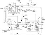
도 7은 다수의 컨테이너를 포함하는 자동 분배 스테이션 내에 이용될 수 있는 CO2 공급 매니폴드로부터 CO2 액체를 도입하기 위한 공정 흐름 개략도.
도 8은 CO2 스노우 블록을 자동으로 투입하기 위해 컨테이너가 내부로 로딩될 수 있는 투입 스테이션을 도시하는 도면.
도 9a는 컨테이너의 내부로부터 CO2 스노우 블록을 분배할 준비가 된 선택된 컨테이너의 시작 배향(starting orientation)을 도시하는 도면.
도 9b는 액추에이터 조립체가 컨테이너의 측부들을 따라 상향 힘을 가한 결과로서 도 9a의 위치에 대해 반시계 방향으로 90° 회전되어진 선택된 컨테이너의 결과로서 생성된 중간 배향을 도시하는 도면.
도 9c는 CO2 스노우 블록이 컨테이너의 내부로부터 선택된 컨테이너 아래에 위치된 상자 내로 방출될 수 있는, 도 9b의 위치에 대해 반시계 방향으로 추가의 45° 회전되어진 선택된 컨테이너의 최종 경사 배향을 도시하는 도면.1A is a representative perspective view of a container and top plate with filling conduits attached to the top plate for producing carbon dioxide (CO2) snow blocks in an automated filling dispensing station in accordance with principles of the present invention.
FIG. 1B is a cross-sectional view of FIG. 1A , detailing the gas flow of CO2 through the meshed sheet of the top plate.
FIG. 2A illustrates aspects of an automated dispensing station for generating CO2 snow blocks in two different sized containers, each container shown in its respective idle orientation, in accordance with the principles of the present invention; FIG. .
FIG. 2B illustrates aspects of the automatic dispensing station of FIG. 2A, with each of the two containers shown in their respective filling orientation, in accordance with the principles of the present invention;
Figure 3 shows an exemplary actuation mechanism used to dispense CO2 snow blocks from one of the containers previously selected for filling and located at an automatic dispensing station.
FIG. 4 is an automatic, transported under selected container filled with CO2 snow blocks and tilted in a dispensing orientation so that the boxes can be fed into the inlet of a conveyor system that transfers the CO2 snow blocks from the container into the boxes as part of an automated vending system. Diagram showing aspects of a conveyor system located within a distribution station.
5 is a diagram illustrating a control method used to effectuate an automatic dispensing station, in accordance with the principles of the present invention;
Fig. 6 shows the control method used to effect an automatic dosing operation into a single container loaded into the dosing station of Fig. 8;
7 is a process flow schematic for introducing CO2 liquid from a CO2 supply manifold that may be used in an automatic dispensing station comprising multiple containers.
Figure 8 shows a dosing station into which a container can be loaded for automatically dosing CO2 snow blocks.
FIG. 9A shows the starting orientation of a selected container ready to dispense CO2 snow blocks from the interior of the container.
FIG. 9B shows an intermediate orientation created as a result of the selected container being rotated 90° counterclockwise relative to the position of FIG. 9A as a result of the actuator assembly applying an upward force along the sides of the container.
FIG. 9C shows the final tilt orientation of the selected container rotated an additional 45° counterclockwise relative to the location of FIG. 9B where CO2 snow blocks can be released from the interior of the container into a box positioned below the selected container. .
설명되는 바와 같이, 일 태양에서, 본 발명은 자동 분배 스테이션으로부터 입수가능한 다양한 크기의 CO2 스노우 블록을 자동으로 생성하기 위한 방법을 제공한다. 사용자는 분배 스테이션 내에 위치된 컨베이어 시스템의 입구 및 출구 접근 윈도우로부터, 생성된 CO2 스노우 블록에 용이하게 접근할 수 있다. 본 발명의 주문형 생성은 사용자가 CO2 스노우 블록 또는 드라이아이스의 재고를 현장에서 유지할 필요성을 제거한다.As will be described, in one aspect, the present invention provides a method for automatically creating CO2 snow blocks of various sizes available from an automatic dispensing station. A user can easily access the produced CO2 snow blocks from the entrance and exit access windows of the conveyor system located within the distribution station. The create-on-demand of the present invention eliminates the need for users to maintain an on-site inventory of CO2 snow blocks or dry ice.
용어 "CO2 스노우" 및 "드라이아이스"가 동일한 의미를 가지며, 본 명세서와 전반에 걸쳐 상호교환가능하게 사용되어 고화된 CO2의 입자들을 의미할 수 있는 것으로 이해되어야 한다.It should be understood that the terms “CO2 snow” and “dry ice” have the same meaning and can be used interchangeably throughout this specification to mean particles of solidified CO2.
본 명세서와 전반에 걸쳐 상호교환가능하게 사용될 수 있는 "CO2 스노우 블록" 또는 "CO2 블록" 둘 모두는 조밀하게 유지된 입자들로 이루어진 임의의 형상의 실질적으로 블록-유사인 형태의 CO2 스노우 입자들의 생성을 의미하고자 한다.Both "CO2 snow blocks" or "CO2 blocks", which may be used interchangeably throughout this specification, refer to CO2 snow particles in a substantially block-like form of any shape consisting of closely held particles. meant to create.
본 명세서에 사용되는 바와 같은 "CO2 유체"는 액체상, 기체상, 증기상, 초임계상(supercritical phase), 또는 이들의 임의의 조합을 포함하는 임의의 상을 의미한다.As used herein, “CO2 fluid” means any phase, including liquid phase, gas phase, vapor phase, supercritical phase, or any combination thereof.
본 명세서에 사용되는 바와 같은 "CO2 공급원" 또는 "CO2 액체 공급원"은 실린더, 듀어(dewar), 병(bottle), 및 벌크 또는 마이크로벌크 탱크를 포함하지만 이로 한정되지 않는다."CO2 source" or "CO2 liquid source" as used herein includes, but is not limited to, cylinders, dewars, bottles, and bulk or microbulk tanks.
본 명세서에 사용되는 바와 같은 "도관" 또는 "도관 유동 네트워크"는 튜브, 파이프, 호스, 매니폴드, 및 하나 이상의 유동 경로를 생성하고/하거나 유체의 통과를 허용하기에 충분한 임의의 다른 적합한 구조물을 의미한다.As used herein, “conduit” or “conduit flow network” refers to tubes, pipes, hoses, manifolds, and any other suitable structure sufficient to create one or more flow paths and/or permit the passage of fluids. it means.
본 명세서에 사용되는 바와 같은 "연결된" 또는 "작동가능하게 연결된"은, 달리 명시되지 않는 한, 기구(instrumentation), 밸브 및 도관을 포함하지만 이로 한정되지 않는, 파이핑 및 조립체와 같은 2개 이상의 구성요소들 사이에서 유체, 기계적, 화학적 및/또는 전기적 연통을 가능하게 하는 2개 이상의 구성요소들 사이의 직접 또는 간접 연결을 의미한다.As used herein, “connected” or “operably linked” means, unless otherwise specified, two or more components, such as piping and assemblies, including but not limited to instrumentation, valves, and conduits. means a direct or indirect connection between two or more components enabling fluid, mechanical, chemical and/or electrical communication between the elements.
본 명세서에 사용되는 바와 같은 "아이템"은, 생물학적 샘플, 예를 들어 혈액, 소변 및 조직 샘플들 또는 이들의 구성 성분; 신선 식료품(perishable food), 예를 들어 고기, 가금류 고기, 생선 및 낙농 제품; 개인 케어 아이템; 및 화학물질을 포함하지만 이로 한정되지 않는, 냉동으로 또는 소정 온도 미만으로 유지되지 않으면 부패, 열화 및/또는 구조적 변경 또는 변질되기 쉬울 수 있는 임의의 온도-민감성 상품, 제품 또는 보급품을 의미한다.As used herein, “item” includes biological samples, such as blood, urine and tissue samples or components thereof; perishable food such as meat, poultry meat, fish and dairy products; personal care items; and any temperature-sensitive commodity, product or supply, including but not limited to chemicals, that may be susceptible to decay, deterioration and/or structural alteration or deterioration if not kept frozen or below a certain temperature.
본 명세서에 사용되는 바와 같은 "투입"은 CO2 유체를 외부 CO2 공급원으로부터, 외부 CO2 공급원에 작동가능하게 연결된 컨테이너 내로 도입하는 공정을 의미한다.“Introduction” as used herein refers to the process of introducing CO2 fluid from an external CO2 source into a container operably connected to the external CO2 source.
본 명세서에 사용되는 바와 같은 "컨테이너"는, 주형 공동(mold cavity), 실린더, 듀어, 병, 탱크, 배럴, 벌크 및 마이크로벌크를 포함하지만 이로 한정되지 않는, CO2 유체를 수용할 수 있는 임의의 저장, 충전, 배송 또는 운반가능 베셀을 의미한다.As used herein, "container" is any container capable of holding a CO2 fluid, including but not limited to mold cavities, cylinders, dewars, bottles, tanks, barrels, bulk and microbulks. Means a vessel capable of being stored, filled, shipped or transported.
"운반가능"은 공중, 지상 또는 물을 포함하지만 이로 한정되지 않는 임의의 알려진 수단에 의해 사용자 위치로부터 다른 목적지로 이동, 운반 또는 운송될 수 있는 기기(apparatus)를 의미한다. 운반 또는 운송은, 소포 우편(parcel post), 유피에스(UPS)(등록상표) 운송 서비스, 페덱스(FedEx)(등록상표) 운송 서비스 등을 포함하지만 이로 한정되지 않는 다양한 포장 배송 서비스를 통해 일어날 수 있다."Transportable" means an apparatus capable of being moved, carried or transported from a user's location to another destination by any known means, including but not limited to air, land or water. Shipping or shipping may occur via various package delivery services, including but not limited to parcel post, UPS® shipping service, FedEx® shipping service, and the like. there is.
후술되는 실시예들은 단지 예에 의한 것이며, 본 발명은 도면에 예시된 실시예들로 제한되지 않는다. 또한, 도면이 축척대로 되어 있지 않고, 어떤 경우에는 제조 및 조립의 종래의 상세 사항과 같은, 실시예의 이해를 위해 필요하지 않은 상세 사항이 생략되었다는 것이 이해되어야 한다. 정확한 도관 및 밸빙(valving) 구성이 축척대로 도시되어 있지 않고, 본 발명의 원리에 따른 자동화 충전 공정 및 자동 투입 공정의 다양한 태양을 더 잘 예시하기 위해 소정의 특징부가 각각의 도면에서 의도적으로 생략된다는 것이 또한 이해되어야 한다.The embodiments described below are by way of example only, and the present invention is not limited to the embodiments illustrated in the drawings. It is also to be understood that the drawings are not to scale and in some cases details not necessary for an understanding of the embodiments have been omitted, such as conventional details of manufacture and assembly. that the exact conduit and valving configurations are not drawn to scale and certain features are intentionally omitted from each figure to better illustrate various aspects of an automated filling process and an automated dosing process in accordance with the principles of the present invention; that should also be understood.
유사한 요소가 동일한 도면 부호로 지칭되는 도면을 참조하여 실시예들이 기술된다. 실시예들의 다양한 요소들의 관계 및 기능은 하기 상세한 설명에 의해 더 잘 이해된다. 상세한 설명은 본 발명의 범주 내에 있는 것으로서 다양한 순열 및 조합의 특징, 태양 및 실시예를 고려한다. 따라서, 본 발명은 이들 특정 특징, 태양 및 실시예, 또는 이들 중 선택된 하나 또는 그 이상의 것의 그러한 조합들 및 순열들 중 임의의 것을 포함하거나, 이로 이루어지거나 또는 이로 본질적으로 이루어진 것으로서 명시될 수 있다.Embodiments are described with reference to drawings in which like elements are designated by like reference numerals. The relationship and function of the various elements of the embodiments are better understood from the detailed description that follows. The detailed description contemplates various permutations and combinations of features, aspects and embodiments as falling within the scope of this invention. Accordingly, the invention may be specified as comprising, consisting of, or consisting essentially of any of these specific features, aspects and embodiments, or such combinations and permutations of a selected one or more of these.
본 발명의 일 태양에서, 자동 분배 스테이션 내의 선택된 컨테이너 내로 이산화탄소(CO2) 스노우 블록을 자동으로 충전하는 방법이 도 1a, 도 1b, 도 2a, 도 2b, 도 3, 도 4, 도 5, 도 7, 도 9a, 도 9b 및 도 9c를 참조하여 논의될 것이다. 도 1a 및 도 1b는 CO2 스노우 블록(2)을 제1 컨테이너(10)로부터 임의의 적합한 사용자 상자 내로 판매하기 위해 자동 분배 스테이션(1)(도 2, 도 3, 도 4, 도 5)과 함께 사용되는 제1 컨테이너(10)를 예시한다. 제1 컨테이너(10)는 제1 상부 플레이트(15)와 함께 주형 공동(13)을 포함한다. 주형 공동(13)은 CO2 스노우 블록(2)의 체적을 수용하는 크기로 된 체적을 갖는다. CO2 스노우 블록(2)의 원하는 체적이 자동 분배 스테이션(1)의 프로그래밍가능 논리 제어기(programmable logic controller, PLC)(1085) 내로 입력된다. PLC(1085)는, 주형 공동(13)이 PLC(1085) 내로의 CO2 스노우 블록(2)의 입력된 체적 이상인 체적을 갖는다고 PLC가 판단한 경우에만, 자동 분배 스테이션(1) 내에 위치된 주형 공동(13)을 선택한다. PLC(1085)는 선택된 주형 공동(13)을 충전 배향(도 2b)으로 배향시키고, 필요한 양의 CO2 스노우 블록(2)을 주형 공동(13) 내로 충전하기 위한 자동화 충전 공정을 수행한다. 충전 공정은 바람직하게는 CO2 스노우 블록(2)의 원하는 체적을 달성하기 위한 충전 시간에 기초한다.In one aspect of the present invention, a method of automatically filling carbon dioxide (CO2) snow blocks into selected containers in an automatic dispensing station is provided in FIGS. 1A, 1B, 2A, 2B, 3, 4, 5, 7 , will be discussed with reference to FIGS. 9A, 9B and 9C. 1A and 1B show an automatic dispensing station 1 ( FIGS. 2 , 3 , 4 , 5 ) for dispensing CO2 snow blocks 2 from a
충전의 완료시, CO2 스노우 블록(2)은 주형 공동(13)으로부터, 픽업을 위한 사용자에게 판매되는 사용자 상자(22)(도 4) 내로 전달된다. 구체적으로, 사용자 상자(22)는 입구 윈도우(21)에서 공급되고, 후속적으로 컨베이어 벨트(20)를 따라 사용자가 접근 및 픽업하기 위한 자동 분배 스테이션(1)의 분배 윈도우(14)로 이송된다.Upon completion of filling, the
제1 컨테이너(10)의 구조적 상세 사항이 도 1a 및 도 1b에 도시되어 있다. 주형 공동(13)은 일반적으로 상부 플레이트(15), 저부 벽(16), 및 다수의 수직으로 배향된 측벽(17)을 포함한다. 상부 플레이트(15)는 CO2 스노우의 상당한 손실 없이 기체 CO2가 주형 공동(13)의 내부를 빠져나갈 수 있도록 기체 CO2에 대해서만 투과성이고 CO2 스노우에 대해 실질적으로 불투과성인 분리 장벽 지지체에 의해 특징지어진다. 도 1b를 참조하면, 분리 장벽 지지체는 지지 구조물(19) 및 메시형 시트(18)를 포함한다. 기체 CO2가 빠져나가기 위한 통로를 한정하는 데 임의의 유형의 재료가 이용될 수 있다는 것이 이해되어야 한다.Structural details of the
충전 도관(23)은 상부 플레이트(15)에 연결된 일 단부 및 CO2 공급 매니폴드(1000)에 연결된 다른 단부를 갖는다. 바람직한 실시예에서, 총 4개의 노즐(12)이 충전 도관(23)의 일 단부에 균일하게 분포된다. 각각의 노즐(12)은 대략 90°만큼 서로 이격되고, 각각의 노즐(12)은 동일한 크기의 개구 및 형상을 갖는다. 노즐(12)의 구조는 노즐을 통한 CO2 유체의 실질적으로 균일한 유동을 생성하며, 이는 주형 공동(13) 내에서의 CO2 스노우 블록(2)의 실질적으로 균일한 형성 및 분포의 생성을 허용한다. 노즐(12)은 충전 도관(23)의 수직에 대해 대략 30° 내지 60° 범위의 각도로 충전 도관(23)의 수직으로부터 멀어지게 배향되며, 이에 의해 수직은 주형 공동(13)의 수평 표면에 직각으로 연장된다. 본 발명의 범주로부터 벗어남이 없이 다른 노즐 설계 및 배향이 고려된다는 것이 이해되어야 한다.The filling
도 2a는 다수의 컨테이너를 수용하도록 설계된 자동 분배 스테이션(1)을 도시한다. 점선은 상이한 체적들의 다수의 컨테이너가 내부에 수용될 수 있는 자동 분배 스테이션(1)의 구조적 인클로저(enclosure)를 나타낸다. 구체적으로 그리고 본 발명의 원리를 더 잘 설명하기 위한 간결성의 목적을 위해, 단지 2개의 컨테이너, 즉 도 1a의 제1 컨테이너(10) 및 제2 컨테이너(26)가 도시되어 있다. 제1 컨테이너(10)는 제2 컨테이너(26)보다 작은 체적을 갖는다. 자동 분배 스테이션(1)은 CO2 공급 매니폴드(1000)에 분리가능하게 연결되며, 그 상세 사항이 도 7에 도시되어 있다. 제1 컨테이너(10)는 제1 컨테이너(10)가 제1 주형 공동(13)의 상부로부터 제거된 제1 상부 플레이트(15)를 갖는 유휴 배향으로 도시되어 있다. 유사하게, 제2 컨테이너(26)는 제2 컨테이너(26)가 제2 주형 공동(25)의 상부로부터 제거된 제2 상부 플레이트(28)를 갖는 유휴 배향으로 도시되어 있다. 유휴 배향에 있는 제1 컨테이너(10)도 제2 컨테이너(26)도 CO2 스노우 블록(2)을 수용하지 않는다. 수직 액추에이터(29a, 29b)들은 제1 상부 플레이트(15)에 부착되고, 수축되어 제1 상부 플레이트(15)를 제1 컨테이너(10)로부터 멀어지게 들어올려 유휴 배향을 생성하도록 구성된다. 수직 액추에이터(29a, 29b)들은 연장되어 제1 상부 플레이트(15)가 제1 컨테이너(10) 상으로 하강되게 하여 도 2b의 충전 배향을 생성하도록 구성된다. 유사하게, 수직 액추에이터(30a, 30b)들이 제2 상부 플레이트(28)에 부착되고, 제2 상부 플레이트(28)를 제2 컨테이너(26)로부터 멀어지게 들어올려 유휴 배향을 생성하도록 구성되며, 연장되어 제2 상부 플레이트(28)가 제2 컨테이너(26) 상으로 하강하여 도 2b의 충전 배향을 생성하도록 재구성될 수 있다.2a shows an
PLC(1085)는 공급 매니폴드(1000) 및 자동 분배 스테이션(1)의 다양한 구성요소와 전기적으로 통신하고, 그 결과로서 도 7에 도시된 바와 같은 자동 제어 밸브와 압력 조절 장치, 압력 변환기 및 통기 시스템을 포함한, 다양한 액추에이터, 밸빙을 조절할 수 있다. PLC(1085)와 다양한 구성요소 사이에서 연장되는 도 7에서의 점선은 전기 통신을 나타낸다. 제1 컨테이너(10), 제2 컨테이너(26), 및 상부 플레이트를 들어올리고 하강시키는 것을 담당하는 다양한 액추에이터(29a, 29b, 30a, 30b), 및 주형 공동들을 분배 배향(도 9a, 도 9b, 도 9c를 참조하여 설명될 것임)으로 회전시키는 것을 담당하는 다른 액추에이터 조립체(91a, 91b)들을 포함한 다양한 구성요소와 PLC(1085) 사이에서 PLC(1085)가 통신하는 것이 추가로 이해되어야 한다.The
도 2b는 각자의 상부 플레이트(15, 28)들이 그들의 각자의 컨테이너(10, 26)들의 주연부를 따라 시일(seal)을 형성하기에 충분한 압력으로 그들의 각자의 주형 공동(13, 25)들 상으로 하강되는 충전 배향에서의 제1 컨테이너(10) 및 제2 컨테이너(26)를 도시한다. 주연부 시일은 주형 공동(13/25)들 내의 기체 CO2만이 제1 컨테이너(10)와 제2 컨테이너(26)의 메시형 시트(18, 31)를 통해 각각 빠져나갈 수 있는 것을 보장한다. 구체적으로, 수직 액추에이터(29a, 29b)들은 도 2a에 비해 연장되어 제1 주형 공동(13)의 주연부를 따라 시일을 형성하기에 충분한 압력으로 제1 상부 플레이트(15)가 제1 주형 공동(13) 상으로 하강하게 한다. 수직 액추에이터(30a, 30b)들은 도 2a에 비해 연장되어 제2 주형 공동(25)의 주연부를 따라 시일을 형성하기에 충분한 압력으로 제2 상부 플레이트(28)가 제2 주형 공동(25) 상으로 하강하게 한다. 도 2b는 제1 충전 도관(23) 및 제2 충전 도관(27)이 CO2 공급 매니폴드(1000)에 분리가능하게 연결되는데, 실린더, 듀어, 병, 마이크로벌크 또는 벌크 탱크를 포함하지만 이로 한정되지 않는 임의의 적합한 컨테이너를 포함할 수 있는 CO2 공급원(1090)으로부터 CO2 액체가 CO2 공급 매니폴드를 따라 유동할 수 있음을 도시한다.Figure 2b shows that the respective
자동 분배 스테이션(1)과 관련된 자동화 공정이 이제 기술될 것이다. 바람직한 실시예에서, PLC(1085)는 도 5의 제어 방법(5000)에 의해 CO2 스노우 블록(2)의 충전 및 판매를 제어하는 데 이용된다. PLC(1085)는 자동 분배 스테이션(1)에 매우 근접하게 위치될 수 있다. 이러한 예에서 그리고 본 발명의 원리를 더 잘 설명하기 위한 간결성의 목적을 위해, 자동 분배 스테이션(1)은 제1 컨테이너(10) 및 제2 컨테이너(25)를 수용한다. 그러나, 자동 분배 스테이션(1)이 바람직하게는 상이한 체적들의 보다 많은 개수의 컨테이너를 수용하도록 설계된다는 것이 이해되어야 한다. 일례에서, PLC(1085)는 도 7에 도시된 CO2 공급 매니폴드(1000)의 일부로서 위치된다. PLC(1085)는 바람직하게는 생성될 CO2 스노우 블록(2)의 밀도를 가지고 사전-프로그래밍된다. PLC(1085)는 임의의 밀도를 사용할 수 있지만, 바람직하게는 50 내지 65 lb/ft3, 더 바람직하게는 55 내지 60 lb/ft3을 사용한다. 단계 501에서, PLC(1085)가 활성화될 수 있다. 다음으로, 사용자가 생성될 CO2 스노우 블록(2)의 요구되는 체적을 PLC(1085) 내로 입력한다(단계 502). 사용자는 또한 인간 기계 인터페이스(human machine interface, HMI) 상에서 특정 CO2 스노우 블록 또는 컨테이너(10/26)의 크기 및/또는 형상을 선택할 수 있다. PLC(1085)는 입력된 체적에 응답하여, CO2 스노우 블록(2)의 입력된 체적을 생성할 수 있는 체적을 갖는 적합한 컨테이너를 자동 분배 스테이션(1) 내에서 선택하고 활성화시킨다. PLC(1085)는 제1 컨테이너(10)에 대응하는 주형 공동(13)의 체적이 입력된 부피보다 더 작다고 결정한다. PLC(1085)는 제2 컨테이너(26)에 대응하는 주형 공동(25)의 체적이 CO2 스노우 블록(2)의 입력된 체적과 같거나 이보다 더 크다고 또한 결정한다. 그 결과, PLC(1085)는 CO2의 충전을 위해 사용될 제2 컨테이너(26)를 선택하고, 따라서 제2 컨테이너(26)로 신호를 전송한다.An automated process associated with the
자동 분배 스테이션(1) 내에 위치되는 컨베이어 시스템(4)의 입구 윈도우(21)에 상자(22)(예컨대, 판지 상자)가 공급된다(단계 503). 상자(22)는 사용자에 의해 수동으로 또는 자동으로 공급될 수 있다. 상자(22)는 주형 공동 내에서 생성될 CO2 스노우 블록(2)의 입력된 체적을 수용하는 크기로 된 체적을 갖는다.A box 22 (eg a cardboard box) is fed to the
내부에 CO2를 충전하기 위한 적절한 컨테이너를 선택하였고, 상자(22)가 컨베이어 벨트(20)의 입구(21)를 따라 배치된 상태에서(단계 503), PLC(1085)는 충전-전(pre-fill) 완전성 검사를 수행할 준비가 된다(단계 504). 충전 작업이 시작될 수 있기 전에 다수의 기준을 통과하여야 한다. PLC(1085)는 배기부(1050)와 PLC(1085) 사이의 통신에서 나타나는 압력 스위치 "PS1000"을 통해 통기 시스템(1050)(도 7)이 켜져 있음을 검증한다. 구체적으로, PLC(1085)는 배기 시스템이 켜졌고 CO2 가스 및 CO2 오프 가스가 주형 공동(25)으로부터 배기 도관(1050)을 통해 그리고 이어서 배기 시스템으로 통기될 수 있게 하도록 기능하고 있음을 검증한다. PLC(1085)는 또한 공급 매니폴드(1000) 및 제2 충전 도관(27) 내의 압력이 누설 없이 유지될 수 있는지 여부를 결정한다. 이들 충전-전 완전성 기준들 중 임의의 것이 충족되지 않는 경우, PLC(1085)는 작동을 중단시키고, 모든 충전-전 완전성 검사가 통과될 때까지 사용자가 적절한 보정 동작을 취하도록 메시지 및 상태를 인간 기계 인터페이스(HMI)에 송신한다(단계 505).With the appropriate container selected for filling CO2 therein and the
충전-전 완전성 검사들 각각이 충족되면, PLC(1085)는 적합한 주형 공동을 선택하고, 선택된 적합한 주형 공동을 유휴 배향으로부터 충전 배향으로 활성화시킨다(단계 506). PLC(1085)는 CO2 스노우 블록의 입력된 체적에 응답하여, CO2 스노우 블록(2)의 입력된 체적을 생성할 수 있는 체적을 갖는 적합한 컨테이너를 자동 분배 스테이션(1) 내에서 선택하고 활성화시킨다. PLC(1085)는 제1 컨테이너(10)에 대응하는 주형 공동(13)의 체적이 입력된 부피보다 더 작다고 결정한다. PLC(1085)는 제2 컨테이너(26)에 대응하는 주형 공동(25)의 체적이 CO2 스노우 블록(2)의 입력된 체적과 같거나 이보다 더 크다고 또한 결정한다. 그 결과, PLC(1085)는 CO2의 충전을 위해 사용될 제2 컨테이너(26)를 선택하고, 따라서 단계 506과 관련하여 제2 컨테이너(26)를 유휴 배향(도 2a)으로부터 충전 배향(도 2b)으로 활성화시키기 위해 제2 컨테이너(26)에 신호를 전송한다. 도 2a의 선택된 제2 주형 공동(25)은 제2 상부 플레이트(28)가 제2 주형 공동(25)의 상부로부터 이격된 유휴 배향으로 도시되어 있다. 이 시점에서, CO2 스노우 블록(2)은 제2 주형 공동(25) 내에 수용되어 있지 않다. PLC(1085)는 수직 액추에이터(30a, 30b)들에 신호들을 전송하여 수직 액추에이터(30a, 30b)들이 도 2b에 도시된 바와 같이 종방향으로 하향으로 연장되게 함으로써, 제2 상부 플레이트(28)가 제2 컨테이너(26)의 상부를 향해 하향으로 이동하게 한다. 도 2b에 도시된 바와 같이 제2 주형 공동(25)의 상부 상으로 균일하게 위치될 때까지 수직 액추에이터(30a, 30b)들은 하향으로 계속 이동한다. 도 2b는 제2 컨테이너(26)의 주연부를 따라 시일을 형성하기에 충분한 압력으로 제2 플레이트(28)가 제2 컨테이너(26)의 상부 상으로 하강되었음을 도시한다.If each of the pre-fill integrity checks are met, the
PLC(1085)는 선택된 컨테이너(26)가 충전 배향에 있는 것을 확인하고, 그렇지 않은 경우, PLC(1085)는 선택된 컨테이너(26)를 충전 배향으로 배향시키기 위해 적절한 신호를 중계할 것이다. 제2 컨테이너(26)가 도 2b에 도시된 바와 같이 충전 배향으로 활성화된다는 검증시, PLC(1085)는 선택된 컨테이너(26) 내로의 CO2 스노우 블록(2)의 미리 결정된 또는 예상되는 충전 시간을 다음과 같이 결정할 수 있다(단계 507). PLC(1085)는 공급원(1090)의 증기 헤드스페이스(headspace) 내에서의 CO2의 압력을 측정하는 압력 변환기(1071)(도 7)로부터 신호를 수신한다. 압력 변환기(1071)는 CO2의 압력에 대응하는 신호를 PLC(1085)로 중계한다. 이러한 압력 판독치 및 제2 충전 도관(27)에서의 노즐(12)들의 총 체적(그의 대표적인 개략도가 도 1b에 도시됨)에 기초하여, PLC(1085)는 압력 대 노즐(12)들의 총 체적의 순람표(look-up table)에 의해 경험적으로 결정되는, CO2 액체-함유 스트림의 예상되는 질량 유량을 결정할 수 있다. 질량 유량이 결정되었다면, 선택된 제2 컨테이너(26) 내로의 예상되는 충전 시간(즉, 미리 결정된 충전 시간)은, 요구되는 CO2 스노우 블록의 입력된 체적과 생성될 CO2 스노우 블록의 사전-프로그래밍된 밀도(예컨대, 바람직하게는 55 내지 60 lb/ft3)의 곱을 경험적으로 결정된 질량 유량으로 나눈 것으로서 PCL(1085)에 의해 계산된다.The
PLC(1085)가 미리 결정된 충전 시간을 계산한 상태에서, PLC(1085)는 충전 공정 전에 공급 매니폴드(1000)의 가압을 개시하기 위해 시작 버튼을 활성화하도록(단계 508) 사용자 메시지를 프롬프트한다. 제2 충전 도관(27)과 연관된 도 7의 밸빙, 기구 및 구성요소는 이제 설명되는 바와 같이 CO2 공급원 공급 매니폴드(1000)와 연결되고 CO2 가스 및 CO2 액체를 수용하도록 구성된다. 가스 도관(1091)은 압력 변환기(1071, 1070)들 및 압력 표시기(1078)를 포함한다. 압력 변환기(1071)는 CO2 공급원(1090) 내의 헤드스페이스의 압력을 측정하고; 압력 표시기(1078)는 감압 밸브(1080)("PRV 1100")에 의해 감소된 후에 CO2 가스 스트림의 압력을 측정하며; 압력 변환기(1070)는 선택된 제2 컨테이너(26)로 들어가는 CO2-액체 함유 스트림의 압력을 측정한다. 개방 위치에서 구성된 CO2 증기 밸브(1094), 개방 위치에서 구성된 CO2 제어 밸브(1100), 폐쇄 위치에서 구성된 CO2 액체 인출 밸브(1093), 및 폐쇄 위치에서 구성된 CO2 제어 밸브(1200)에 의해, CO2 가스가 CO2 공급원(1090)의 증기 헤드스페이스로부터 인출되고 가스 도관(1091) 내로 유동한다. 압력 조절기(1080)("PRV 1100")는 압력 표시기(1078)에 의해 측정되는 바와 같이, CO2 공급원(1090)으로부터 인출되는 CO2 가스의 압력을 공급원 압력(예컨대, 350 내지 400 psig)으로부터 약 150 psig로 감소시킨다. CO2 가스는 바람직하게는 액체-함유 CO2의 압력이 소정 압력(예컨대, 약 150 psig) 미만으로 감소하는 것을 방지하는 양으로 부가되어, 액체가 공급 매니폴드(1000)의 도관 및 제2 충전 도관(27)의 일부분 내에서 고체 및/또는 기체로의 상 변화를 조기에 겪는 압력으로 떨어지지 않는 것을 보장한다.With the
매니폴드(1000)의 도관을 적절하게 가압하는 것에 더하여, 임의의 시간량 동안 임의의 잔류물 및/또는 불순물을 유동시키고 퍼징(purging)하기 위해 CO2 가스가 선택적으로 부가될 수 있다. 일례에서, 퍼징 공정은 대략 30초 내지 약 2분 동안 계속될 수 있다. CO2 가스가 가스 도관(1091)의 다양한 부분을 통해 유동함에 따라, 임의의 잔류물 및/또는 불순물이 또한 퍼징될 수 있다. CO2 가스는 밸브(1301)를 개방 상태로 설정하고 밸브(1302)를 폐쇄 상태로 설정함으로써 선택된 제2 컨테이너(26) 내로 안내될 수 있다. 충전 공정의 이러한 단계에서의 컨테이너(26)는 임의의 상당한 양의 CO2 스노우 미립자 또는 CO2 스노우 블록(2)을 수용하고 있지 않다. CO2 가스는 충전 도관(27)을 통해 하향 방향으로 유동하여 주형 공동(25)으로 들어간다. CO2 가스는 후속적으로 컨테이너(26)로부터 제2 상부 플레이트(28)의 메시형 시트(31)를 통해 빠져나간다(예컨대, 상향 화살표로 도 1b에 더 상세히 도시된 바와 같이 실질적으로 수직으로 배향된 방향으로 인출됨).In addition to properly pressurizing the conduits of the manifold 1000, CO2 gas may optionally be added to flow and purging any residue and/or impurities for any amount of time. In one example, the purging process may continue for approximately 30 seconds to about 2 minutes. As the CO2 gas flows through the various portions of
PLC(1085)가 선택된 충전 도관(27) 내의 압력을 결정하고 CO2 공급 매니폴드(1000)가 액체 CO2의 상 변화를 방지하기에 충분한 압력 이상일 때(예컨대, 바람직하게는 150 psig 이상, 더 바람직하게는 200 psig 내지 최대 약 350 psig), 선택된 컨테이너(26) 내로의 CO2 스노우 블록(2)의 충전이 시작된다(단계 509). CO2 증기 밸브(1094)가 개방 위치에 남아 있을 수 있고; 제어 밸브(1100)는 개방 위치에 남아 있음으로써, 액체 CO2가 컨테이너(26) 내로 충전되기 전에 그리고 그 동안에 매니폴드(1000) 내에 적절한 가스 가압이 존재하는 것을 보장할 수 있다. CO2 공급원(1090)으로부터의 액체 CO2의 유동을 개시하기 위해, 제어 밸브(1302)가 폐쇄 위치에서 설정되어, 액체-함유 CO2가 제1 컨테이너(10)(즉, PLC(1085)에 의해 결정된 바와 같은 선택되지 않은 컨테이너) 내로 유동하지 않는 것을 보장하고, 제어 밸브(1301)는 개방 위치에서 설정되어 액체-함유 CO2가 제2 컨테이너(26)(즉, PLC(1085)에 의해 결정된 바와 같은 선택된 컨테이너) 내로 유동하게 한다. 도 7을 참조하면, CO2 공급원(1090)으로부터의 액체-함유 CO2는 액체 도관(1092)을 따라 제어 밸브(1301)를 통해 유동하고, 이어서 (도 1b에 도시된 바와 같이) 선택된 제2 컨테이너(26)의 제2 충전 도관(27) 내로 하향 방향으로 도입된다. 체크 밸브(1067)는 액체-함유 CO2의 압력이 도관(1091) 내의 CO2 가스가 CO2 공급원(1090) 내로 역류하게 하는 것을 방지한다.When the
CO2-함유 액체는 제2 충전 도관(27)의 노즐(12)들로부터 나와서 선택된 제2 컨테이너(26)의 선택된 주형 공동(25)으로 들어간다. 바람직한 실시예에서, 제2 충전 도관(27)의 단부는 도 1b에 도시된 바와 같이 CO2-함유 액체를 선택된 주형 공동(25) 내로 안내하거나 주입하도록 경사진 4개의 노즐(12)을 갖는다. 액체-함유 CO2가 노즐(12)들을 통과해 선택된 주형 공동(25) 내로 들어감에 따라 압력 및 온도 강하가 발생하여, 주형 공동 내부에서 CO2 스노우의 고체 입자들 및 CO2 오프 가스를 생성한다. CO2 오프 가스는 제2 상부 플레이트(28)의 메시형 시트(18)를 통과하는 반면, 고체 미립자들은 너무 커서 메시형 시트(18)를 가로질러 유동할 수 없고 따라서 주형 공동(25) 내에 포획된 채로 유지된다. 입자들 및 가스는 컨테이너(26)의 상부 에지를 따라 빠져나가지 않는데, 그 이유는 제2 상부 플레이트(28)를 충전 동안에 주형 공동(25)의 상부에 대항하여 충분히 가압되는 상태로 유지하는 액추에이터(30a, 30b)들의 결과로서 제2 컨테이너(26)의 주연부가 밀봉되기 때문이다. CO2 오프 가스가 통기 가스(vented gas)로서 메시형 시트(31)를 통과함에 따라, 주형 공동(25) 내에 CO2 스노우 블록(2)을 형성하도록 CO2 스노우의 고체 입자들을 패킹함으로써 CO2 스노우 블록(2)의 생성을 시작하는 바람직한 효과를 갖는다. 자동화 충전과 관련하여 본 명세서에 사용되는 바와 같은 용어 "패킹"은 적합한 밀도의 CO2 스노우 블록(2)으로의 스노우 입자들의 압축을 지칭한다. 패킹은 선택된 주형 공동(25) 내에서 생성될 수 있는 CO2 스노우 블록(2)의 양에 영향을 줄 수 있다. 이러한 방식으로, 본 발명은 CO2 스노우 블록(2)을 형성하도록 스노우 입자들의 패킹 밀도를 개선하기 위해 통기 가스의 형성을 이용하는 능력을 갖는다. CO2 통기 가스는 도 1b에 화살표로 도시된 바와 같이 제2 상부 플레이트(28)의 메시형 시트(31)의 개구들을 가로질러 유동함으로써, 과도한 압력이 제2 주형 공동(25) 내에 축적되는 것을 방지한다. 가스가 제2 충전 도관(27)의 수직에 대해 임의의 각도로 인출될 수 있으며, 이에 의해 수직은 선택된 주형 공동(25)의 수평 표면에 직각으로 연장된다는 것이 이해되어야 한다. 통기 가스는 이어서, 제2 충전 도관(27)에 작동가능하게 연결된 배기 도관(1050) 내로 안내될 수 있다.The CO2-containing liquid exits the
CO2 스노우의 입자들은 선택된 주형 공동(25) 내에서 블록-유사 형태로 계속 형성된다. 타이머는 경과 시간을 계속 모니터링하고, PLC(1085)로 전송되는 경과 시간에 대한 대응 신호를 생성할 수 있다. PLC(1085)는, 경과 시간이 미리 결정된 충전 시간보다 작은 한(단계 510), CO2-함유 액체가 도관(1092)을 따라 유동하게 한다.Particles of CO2 snow continue to form in a block-like form within the selected
PLC(1085)가 경과 시간이 미리 결정된 충전 시간에 도달했다고 결정한 때, 충전이 정지된다. 구체적으로, PLC(1085)는 제어 밸브(1301)에 신호를 전송하여 제어 밸브를 폐쇄 위치로 구성함으로써, CO2-함유 액체가 선택된 컨테이너(26) 내로 계속 유동하는 것을 방지한다. 주 액체 인출 밸브(1093)가 또한 폐쇄된다. 충전 공정은 이러한 방식으로 정지된다(단계 511). 액체 CO2의 유동을 정지시키는 것에 응답하여, 요구되는 경우, 매니폴드(1000)의 도관 및/또는 선택된 컨테이너(26) 내에서 임의의 불순물 또는 잔류물을 퍼징하기 위한 수단으로서 소정 지속기간 동안, 기체 CO2가 가스 도관(1091)을 따라 충전 도관(807) 내로 그리고 컨테이너 내로 다시 유동하기 시작할 수 있다. CO2 가스가 선택된 컨테이너(26) 내로 유동하고 이어서 통기됨에 따라, 스노우 블록(2)이 더욱 패킹될 수 있다.When the
매니폴드(1000)의 가동중지(shut down)가 또한 단계 511의 일부로서 일어날 수 있다. 잔류 액체 CO2는 제어 밸브(1200)로부터 주 액체 인출 밸브(1093)까지 연장되는 액체 도관(1092)의 부분을 따라 포획될 수 있다. 안전 릴리프 밸브(1086, 1087)("SRV 1102", "SRV 1200")들은 가스 도관(1091) 및/또는 액체 도관(1092) 내에 포획될 수 있는 잔류 압력을 제거하도록 설계된다. 그를 따른 포획된 액체 CO2가 궁극적으로 CO2 가스로 승화될 수 있음에 따라, 압력 축적은 일례에서 400 psig에서 작동하도록 설정된 안전 릴리프 밸브(1087)에 의해 제거될 수 있다. 안전 릴리프 밸브(1086)는 또한 CO2 가스(1091) 도관 내에서의 압력 축적이 상한(예컨대, 400 psig)에 도달하면 그리고 도달한 때 압력을 제거하도록 역할한다.A shutdown of the manifold 1000 may also occur as part of
충전 공정을 종료하였을 때, PLC(1085)는 선택된 주형 공동(25)을 충전 배향으로부터 분배 배향으로 활성화시킨다(단계 512). 먼저, 액추에이터(30a, 30b)들이 수축되어 상부 플레이트(28)가 도 2a에 도시된 바와 유사한 방식으로 주형 공동(25)의 상부로부터 멀리 들어올려지게 한다. 도 3은 상부 플레이트(28)가 제거된 상태의, 요구되는 체적의 CO2 스노우 블록(2)을 수용한 선택된 주형 공동(25)의 확대도를 도시한다. 주형 공동(25)은 CO2 스노우 블록(2)을 상자(22) 내로 분배할 준비가 되는데, 상자는 컨베이어 벨트(20)를 따라 주형 공동(25) 아래에 위치된 위치로 이송되어, CO2 스노우 블록이 주형 공동(25) 내부로부터 상자(22) 내로 떨어짐에 따라 상자가 CO2 스노우 블록(2)을 수용할 수 있다. 도 4는 컨베이어 벨트(20)를 따른 상자(22)의 이동을 도시한다. 구체적으로, 도 4는 상자(22)가 컨베이어 윈도우의 입구(21)로부터, 상자가 CO2 블록(2)을 수용하는 주형 공동(25) 아래의 위치로, 그리고 최종적으로 요구된 CO2 블록(2)이 상자 내부에 로딩된 상태에서 픽업할 준비가 된 컨베이어 시스템(4)의 분배 윈도우로 이동하는 컨베이어 시스템(4)을 도시한다. 상자(22)가 요구되는 위치에 있는 것으로 결정된 때(단계 513), 이제 도 9a, 도 9b 및 도 9c의 시퀀스로 묘사되는 바와 같이, 주형 공동(25)이 기울어져 그 내부의 CO2 스노우 블록(2)이 상자(22) 내로 분배되게 한다. 도 3 및 도 9a는 분배 공정의 시작에서의 주형 공동(25)을 도시한다. 도 3은 액추에이터 조립체(91a) 및 액추에이터 조립체(91b)가 선택된 주형 공동(25)의 제1 측부(17a) 및 제2 측부(17b)에 각각 작동가능하게 연결되는 것을 도시한다. 본 명세서에 사용되는 바와 같이 그리고 도 3을 참조하면, "a"가 뒤따르는 도면 부호는 주형 공동(25)의 제1 측부를 지칭하도록 의도되고, "b"가 뒤따르는 동일한 도면 부호는 주형 공동(25)의 제2 측부(17b)를 지칭하도록 의도되며, "a" 또는 "b"가 뒤따르지 않는 동일한 도면 부호는 주형 공동(25)이 사시도로 도시되지 않은 경우에 (예컨대, 도 9a, 도 9b 및 도 9c와 관련하여) 주형 공동(25)과 연관된 구조물을 전반적으로 지칭하도록 의도된다. 예로서, 액추에이터 조립체(91a)는 도 9a에 도시된 바와 같이 주형 공동(25)의 제1 측부(17a)에 작동가능하게 연결되는 액추에이터 조립체를 지칭하고, 액추에이터 조립체(91b)는 주형 공동(25)의 제2 측부(17b)에 작동가능하게 연결되는 액추에이터 조립체를 지칭하며, 액추에이터 조립체(91)는 도 9a, 도 9b 및 도 9c의 단면도들에 도시된 바와 같은 주형 공동(25)의 액추에이터 조립체를 전반적으로 지칭한다. 액추에이터 조립체(91a, 91b)들 각각은 각자의 슬롯(92a, 92b)들 내로 맞물리는 각자의 핀(93a, 93b)들을 통해 선택된 주형 공동(25)의 제1 측부(17a) 및 제2 측부(17b)에 맞물려 유지된다. 액추에이터 조립체(91a, 91b)들은 (후술되는 바와 같이) 핀(93a, 93b)들이 대응하는 슬롯(92a, 92b)들을 따라 활주할 때 주형 공동(25)이 회전하게 한다. 주형 공동(25)은 지지 레그(leg) 구조물(90a, 90b)들에 연결된 피벗 지점(94a, 94b)을 중심으로 피벗할 수 있다. 지지 레그 구조물(90a, 90b)들은 도 2a, 도 2b, 도 3 및 도 4에 도시된 바와 같이 주형 공동(25)을 현수시킨다. 도 3에 도시된 바와 같은 액추에이터 조립체의 상세 사항이 도 4의 컨베이어 시스템으로부터 생략되고, 자동 분배 스테이션(1)을 도시하는 다른 도면들과 관련하여 본 발명의 핵심적인 태양을 명확하게 기술하는 목적을 위해 이들 도면으로부터 생략된다는 것이 이해되어야 한다.Upon completion of the filling process, the
도 3 및 도 9a의 배향으로부터 시작하여, 액추에이터 조립체(91a) 및 액추에이터 조립체(91b) 각각은 주형 공동(25)의 제1 측부(17a) 및 제2 측부(17b) 상의 각각의 핀(93a, 93b)들에 각각 전달되는 상향력을 가하도록 활성화된다(예컨대, PLC(1085)에 의해 프로그래밍됨). 핀(93a, 93b)들은 슬롯(92a, 92b)들 내에서 상향으로 이동하는 것이 제한된다. 그 결과, 피벗(94a, 94b)으로부터 멀리 동일한 거리로 각각 이격되어 있는 핀(93a, 93b)들은 주형 공동(25)이 반시계 방향으로 회전하게 하는 토크를 가한다. 주형 공동(25)이 반시계 방향으로 회전함에 따라, 슬롯(92a, 92b)들은 수직으로 배향됨으로써, 액추에이터 조립체(91a, 91b)들의 각자의 아암들이 슬롯(92a, 92b)들을 따라 상향으로 연장되게 한다. 도 9b는 액추에이터 조립체(91a, 91b)들의 아암들이 슬롯(92a, 92b)들 내로 그리고 슬롯들을 따라 상향으로 부분적으로 확장된, 피벗(94a, 94b)을 중심으로 반시계 방향으로 90도 회전되어진 회전된 주형 공동(25)의 중간 구성을 도시한다. 액추에이터 조립체(91a, 91b)들의 아암들은, 아암들 및 각자의 핀(93a, 93b)들이 도 9c에 도시된 바와 같이 슬롯(92a, 92b)들의 최상부 에지로 이동할 때까지, 주형 공동(25)의 추가적인 반시계 방향 회전을 생성하도록 그들의 각자의 핀(93a, 93b)들을 통해 상향 힘을 계속 가한다. 도 9c는 도 9b에 대한 추가의 45° 반시계 방향 회전을 나타낸다. 도 9c의 기울어진 배향은 CO2 스노우 블록(2)이 주형 공동(25)의 내부로부터 상자(22) 내로 방출되게 할 수 있는데(단계 515), 이 시점에서 상자는 도 4에 도시된 바와 같이 주형 공동(25) 아래에 위치된다. 도 4는 CO2 스노우 블록(2)이 상자(22) 내로 방출되었음을 나타내기 위해 뒤집힌 주형 공동(25)을 도시한다. 상자(22) 내의 표기 "2"는 상자(22)가 CO2 스노우 블록(2)을 수용하고 있음을 나타내도록 의도된다.Starting from the orientation of FIGS. 3 and 9A ,
CO2 스노우 블록(2)이 주형 공동(25)으로부터 방출되어 상자(22) 내로 분배된 상태에서, 액추에이터 아암들이 후퇴되어, 핀(93a, 93b)들 및 이에 부착된 아암들이 슬롯(92a, 92b)들을 따라 하향으로 이동하게 하여, 이 단계에서 주형 공동(25)의 유휴 배향을 나타내는 도 9a의 배향으로 재구성된다(단계 516). CO2 스노우 블록(2)을 내부에 갖는 상자(22)는 컨베이어 벨트(20)를 따라, 픽업을 위해 준비가 된 컨베이어 시스템(4)의 출구/분배 윈도우(14)로 이송된다(단계 517).With the
자동 분배 스테이션(1) 내로의 자동화 충전이 미리 결정된 충전 시간에 기초하여 수행되었지만, 자동화 충전이 또한 다른 기준에 기초하여 일어날 수 있다. 예를 들어, PLC(1085)는, 예로서 CO2 스노우 블록(2)의 미리 규정된 중량; 선택된 주형 공동 내의 압력; CO2 스노우 블록(2)의 커패시턴스; 컨테이너 내의 온도; 또는 선택된 주형 공동의 상부 플레이트의 변형을 포함한, 충전을 위한 다른 설정점을 사용할 수 있다.Although automated filling into the
다른 실시예에서, 자동 분배 스테이션(1)의 사용에 대한 대안으로서, CO2 스노우 블록을 투입 스테이션 내의 단일 컨테이너 내로 다시 자동으로 투입하는 방법이 수행될 수 있다. 도 6은 연관된 제어 방법(6000)을 도시하고, 도 8은 예시적인 투입 스테이션(800)을 도시한다. 투입 스테이션(800)의 입구는 CO2 공급 매니폴드(1000)에 연결되고, 투입 스테이션(800)의 출구는 통기 시스템(801)에 연결된다. CO2 공급 매니폴드(1000)는, 자동 분배 스테이션(1)이 이제 도 8의 투입 스테이션으로 대체된 것을 제외하고는, 실질적으로 동일하다. PLC(1085)는 투입 스테이션(800), CO2 공급 매니폴드(1000), 통기 시스템(801) 및 그의 연관된 구성요소들과 전기적으로 통신한다. PLC(1085)를 활성화시킨 때(단계 600), 충전을 위해 컨테이너가 선택된다(단계 601). 컨테이너는 CO2 스노우 블록이 투입될 수 있는 임의의 적합한 상자일 수 있다. 컨테이너는 투입 스테이션(800) 내에 배치된다(단계 602). 전술된 바와 같이, 충전-전 완전성 검사들(단계 603)이 PLC(1085)에 의해 수행된다. 추가적인 충전-전 완전성 검사로서, 도어(803)가 로킹되어 있는지 여부를 도어 센서가 결정한다. 충전-전 완전성 검사들 중 임의의 것을 충족시키지 못하는 것은 사용자가 적절한 동작을 취하도록 PLC(1085)가 적절한 HMI 메시지를 생성하게 촉구할 것이다(단계 604).In another embodiment, as an alternative to the use of the
모든 충전-전 완전성 검사들이 완료되면, 컨테이너는 유휴 배향으로부터 충전 배향으로 활성화된다(단계 605). 제한하고자 하는 것이 아니라 예로서, 충전 배향은 컨테이너의 상부 상으로 배치되어 주연부를 따라 시일을 생성하는 하나 이상의 수직 액추에이터에 의해 컨테이너의 상부 상으로 상부 플레이트를 구성하는 것을 포함할 수 있다. 컨테이너가 도 1a, 도 1b, 도 2a 및 도 2b와 관련하여 기술된 바와 같이 상부 플레이트 및 주형 공동을 이용할 필요가 없다는 것이 이해되어야 한다. 따라서, 전술된 바와 같은 상부 플레이트 및 주형 공동이 필요하지 않은 경우, 충전 배향은 컨테이너의 상부 및 충전 도관에 작동가능하게 연결되는 적합한 투입기(charger)를 도입하고 배향하는 것을 포함할 수 있다. 충전 배향은 또한 투입 스테이션(800)에 제공되는 안전 인터로크들을 제공하여 도어(803)는 CO2 투입 동안에 로킹된 상태로 유지되고, 컨테이너는 투입 스테이션(800)의 내부 내에 확실한 방식으로 로딩된다.When all pre-fill integrity checks are complete, the container is activated from the idle orientation to the filled orientation (step 605). By way of example and not intending to be limiting, the filling orientation may include constructing a top plate onto the top of the container with one or more vertical actuators disposed on top of the container to create a seal along the periphery. It should be understood that the container need not utilize a top plate and mold cavity as described with respect to FIGS. 1A, 1B, 2A and 2B. Thus, where a top plate and mold cavity as described above is not required, filling orientation may include introducing and orienting a suitable charger operably connected to the top of the container and to the filling conduit. The filling orientation also provides for safety interlocks provided at the
컨테이너가 충전 배향으로 있다는 것이 확인된 때, 사용자는 컨테이너 내에서 생성될 것이 요구되는 CO2 스노우 블록(2)의 요구되는 체적을 입력할 수 있다. 단계 606에서, PLC(1085)는 도 5의 예에서의 단계 507에 대해 전술된 바와 같은 미리 결정된 충전 시간을 결정한다. CO2 스노우 블록의 밀도(예컨대, 55 내지 60 lb/ft3)는 PLC(1085) 내로 사전-프로그래밍되고, 질량 유량은 CO2 압력 대 투입기 내의 노즐들의 총 체적의 순람표로부터 경험적으로 결정된다.When it is confirmed that the container is in the filling orientation, the user can enter the required volume of
사용자는 자동 투입 공정을 개시시키기 위해 시작 버튼을 활성화시킨다(단계 607). 충전은 다음과 같이 시작한다(단계 608). 공급 매니폴드(1000)로부터의 충분한 양의 기체 CO2가 CO2 공급원(1090)의 증기 헤드스페이스로부터, 공급 매니폴드(1000)와 컨테이너 사이에서 연장되는 충전 도관(807) 내로 도입된다. 공급 매니폴드(1000)는 충전 도관(807)에 작동가능하게 연결된다. CO2 가스가 도관 내로 부가되어, 액체 CO2가 매니폴드(1000)의 도관 및 충전 도관(807) 내에서 고체 및/또는 기체로의 상 변화를 조기에 겪을 수 있는 소정 압력 미만(예컨대, 약 150 psig 미만)으로 액체 CO2의 압력이 감소하는 것을 방지하기에 충분한 수준으로 매니폴드(1000)의 도관들을 가압한다. PLC(1085)는 CO2 및 충전 도관(807)의 압력을 측정하는 압력 변환기(1070)(도 7)로부터 공급 매니폴드(1000) 내의 압력을 계속 모니터링한다. 액체 CO2가 상을 변화시키지 않도록 압력이 소정 압력 이상인 것으로 결정된 때, PLC(1085)는 제어 밸브(1200)로 신호를 전송하여 제어 밸브를 개방 위치로 구성한다. 제어 밸브(1200)가 개방 위치에 있는 상태에서, CO2 공급원(1090)으로부터의 액체 CO2가 인출되어 도관(1092)을 따라 유동한다. 액체 CO2의 압력은 매니폴드(1000)를 차지하는 기체 CO2의 압력보다 더 높으며; 그 결과, 액체 CO2가 제1 방향을 따라(예컨대, 컨테이너 내로 실질적으로 수직 및 하향으로) 투입 스테이션(800)의 컨테이너 내로 유동함에 따라 컨테이너 내로의 CO2의 가스 유동이 정지된다. CO2 액체가 컨테이너에 들어감에 따라, 이는 상 변화를 겪어 CO2 스노우 블록 및 오프 가스로 변환된다. 오프 가스는 컨테이너를 빠져나와 배기 도관(1050)을 통해 통기된다. 경과된 충전 시간이 미리 결정된 시간에 도달했다고 PLC(1085)가 결정할 때까지 CO2 액체는 컨테이너 내로 계속 들어간다. 경과 시간이 미리 결정된 시간에 도달했을 때, PLC(1085)는 제어 밸브(1200)에 신호를 중계하여 제어 밸브를 폐쇄 위치로 구성함으로써, CO2 공급원(1090)으로부터의 액체 CO2의 인출을 정지시킨다(단계 610). 주 액체 인출 밸브(1093)가 또한 폐쇄된다. 액체 CO2의 유동을 정지시키는 것에 응답하여, 요구되는 경우, 매니폴드(1000)의 도관 및/또는 컨테이너 내에서 임의의 불순물 또는 잔류물을 퍼징하기 위한 수단으로서 소정 지속기간 동안, 기체 CO2가 가스 도관(1091)을 따라 충전 도관(807) 내로 그리고 컨테이너 내로 다시 유동하기 시작할 수 있다. CO2 가스가 컨테이너 내로 유동하고 이어서 배기 도관(1050) 내로 통기됨에 따라, 스노우 블록이 더욱 패킹될 수 있다. 밸브(1093) 및 밸브(1094)가 도 7에서 수동 밸브들로서 도시되어 있지만, 밸브(1093, 1094)들 각각 대신에 자동 제어 밸브들이 사용될 수 있다는 것이 이해되어야 한다.The user activates the start button to initiate the automatic dosing process (step 607). Charging begins as follows (step 608). A sufficient amount of gaseous CO2 from
이제, 가동중지가 수행될 수 있다(단계 611). 잔류 액체 CO2는 제어 밸브(1200)로부터 주 액체 인출 밸브(1093)까지 연장되는 액체 도관(1092)의 부분을 따라 포획될 수 있다. 안전 릴리프 밸브(1086, 1087)("SRV 1102", "SRV 1200")들은, 투입 스테이션(800)의 다양한 시스템 구성요소 및 매니폴드(1000)가 가동중지된 때 가스 도관(1091) 및/또는 액체 도관(1092) 내에 포획될 수 있는 잔류 압력을 제거하도록 설계된다. 그를 따른 포획된 액체 CO2가 궁극적으로 CO2 가스로 승화될 수 있음에 따라, 압력 축적은 일례에서 400 psig에서 작동하도록 설정된 안전 릴리프 밸브(1087)에 의해 제거될 수 있다. 안전 릴리프 밸브(1086)는 또한 CO2 가스(1091) 도관 내에서의 압력 축적이 상한(예컨대, 400 psig)에 도달하면 그리고 도달한 때 압력을 제거하도록 역할한다.Shutdown can now be performed (step 611). Residual liquid CO2 may be captured along the portion of
단계 611에서 가동중지가 완료된 후에, PLC(1085)는 투입 스테이션(800)의 안전 인터로크들을 비활성화시켜, 투입 스테이션의 도어(803)가 개방되게 하여 컨테이너에 접근하고 CO2 스노우 블록(2)이 내부에 충전된 컨테이너를 제거할 수 있도록 한다.After shutdown is complete in
컨테이너 내로의 자동화 투입이 또한 다른 기준에 기초하여 일어날 수 있다는 것이 이해되어야 한다. 예를 들어, PLC(1085)는, 예로서 CO2 스노우 블록(2)의 미리 규정된 중량; 컨테이너 내의 압력; CO2 스노우 블록(2)의 커패시턴스; 컨테이너 내의 온도; 또는 컨테이너를 밀봉하는 데 이용될 수 있는 상부 플레이트의 변형을 포함한, 충전을 위한 다른 설정점을 사용할 수 있다.It should be understood that automated dosing into containers may also occur based on other criteria. For example, the
기술된 바와 같은 CO2 스노우 블록(2)을 갖는 컨테이너는 본 명세서에서 하기에 정의된 바와 같은 임의의 "아이템"과 함께 사용될 수 있지만, 바람직한 실시예에서, 본 발명은 생물학적 샘플을 재현가능하게 보존하는 데 요구되는 패키징 프로토콜의 컴플라이언스(compliance)를 유지하는 데 특히 도움이 됨으로써, 샘플 열화를 피하고, 샘플이 그의 기능적 상태로 다시 되돌아가게 하며, 그의 목적지 현장에 도달시 적용가능한 시험을 받게 한다. 또한, CO2 스노우 블록(2)은 바람직하게는, 종래의 기술에 의해 생성된 CO2 드라이아이스를 수용하는 표준 드라이아이스 운송 컨테이너와 비교하여, 연장된 냉각 효과 지속기간을 가지고 컨테이너의 필요한 온도를 유지할 수 있는 개선된 패킹 밀도로 생성된다. 연장된 냉각 효과 지속기간은 운반시 샘플 열화의 위험을 감소시킬 수 있고, 본 발명의 운반가능 컨테이너의 제조 및 조립에 관한 비용 및 편리성, 아이템(생물학적 샘플과 같은 샘플을 포함함)이 획득되는 시기, 및 이용될 수 있는 운송 방법의 유형을 최적화하기 위한 더 큰 융통성을 사용자에게 제공한다.A container with a
본 발명에 대한 다수의 변형이 본 발명의 사상으로부터 벗어남이 없이 고려된다. 예를 들어, 자동화 충전 스테이션(도 5)을 위한 제어 방법의 단계들의 시퀀스는 충전-전 완전성 검사들을 통과한 후에 상자(22)가 제 위치에 위치되도록 변경될 수 있다. 투입 스테이션(도 6)에 관하여, PLC는 컨테이너가 투입 스테이션 내로 로딩된 후에 활성화될 수 있다. 부가적으로, 선택된 컨테이너 내로의 CO2 스트림의 주입 방향이 변화될 수 있다. 예를 들어, CO2-함유 액체는 다양한 각도 배향에서 상향으로, 또는 측방향으로, 또는 하향으로 주입될 수 있는데, 이때 정확한 각도는 충전 도관에서의 노즐 형상, 설계 및 기하학적 구조에 의해 결정된다. 유사하게, 선택된 컨테이너 내의 CO2 가스 및 오프 가스는 하향 방향 또는 측방향 방향 또는 상향 및 경사진 방향으로 통기되도록 변화될 수 있다. 부가적으로, 자동 투입 스테이션에 관하여, 제어 방법은 사용자가 스노우 블록(2)의 체적을 입력하고 자동 분배 스테이션(1)의 HMI 상에 열거된 컨테이너를 선택하도록 수정될 수 있다.Many variations on this invention are contemplated without departing from its spirit. For example, the sequence of steps in the control method for an automated charging station (FIG. 5) may be altered such that
본 발명의 자동화 제어 방법은 임의의 컨테이너에 적용될 수 있다. 일 실시예에서, 자동화 제어 방법 및 공정은, 그 상세 사항이 모든 목적을 위해 전체적으로 본 명세서에 참고로 포함된, 미국 특허 출원 제15/645,152호에 기술된 바와 같은 컨테이너와 관련하여 사용될 수 있다. 그러한 컨테이너는 본 발명의 자동 충전 분배 스테이션 또는 투입 시스템의 일부로서 이용될 수 있다.The automated control method of the present invention can be applied to any container. In one embodiment, the automated control methods and processes may be used in conjunction with containers as described in US Patent Application Serial No. 15/645,152, the details of which are incorporated herein by reference in their entirety for all purposes. Such a container may be used as part of an automatic filling dispensing station or dosing system of the present invention.
본 발명의 소정 실시예인 것으로 간주되는 것이 도시되고 기술되었지만, 본 발명의 사상 및 범주를 벗어남이 없이 형태 또는 상세 사항에서의 다양한 수정 및 변경이 용이하게 이루어질 수 있음이 물론 이해될 것이다. 따라서, 본 발명은 본 명세서에 나타내고 기술된 정확한 형태 및 상세 사항으로 한정되지 않으며, 본 명세서에 개시되고 이하에서 청구된 본 발명의 전체보다 더 적은 어떤 것으로 한정되지도 않는다.While what are considered certain embodiments of this invention have been shown and described, it will of course be understood that various modifications and changes in form or detail may be readily made without departing from the spirit and scope of this invention. Accordingly, the present invention is not limited to the precise forms and details shown and described herein, nor is it limited to anything less than the entirety of the invention disclosed herein and hereinafter claimed.
Claims (24)
Translated fromKorean액체 CO2의 압력에 대응하는 제1 신호를 제1 설정점(set point)으로서 제어기 내로 수신하는 단계;
생성될 CO2 스노우 블록의 체적을 제2 설정점으로서 제어기 내로 입력하는 단계;
제어기가 제1 설정점 및 제2 설정점에 기초하여 CO2 스노우 블록의 체적을 생성하기 위한 충전 시간을 결정하는 단계;
제어기가 제2 설정점에 대응하는 내부 체적을 갖는 컨테이너를 선택하는 단계 - 상기 컨테이너는 자동 분배 스테이션 내에 위치되고, 상기 자동 분배 스테이션은 상이한 내부 체적들의 2개 이상의 컨테이너들을 포함함 -;
상기 컨테이너 내로 후속적으로 도입되는 액체 CO2의 상 변화를 방지하는 압력 이상으로 충전 도관을 가압하는 기체 CO2를 상기 액체 CO2를 유동시키기 이전에 충전 도관 내로 유동시키는 단계;
제어기가, 충전 도관 내의 압력이 액체 CO2의 상 변화를 방지하는 압력 이상이라고 제어기가 결정한 때, 액체 CO2 제어 밸브로 하여금 액체 CO2가 충전 도관을 따라 컨테이너 내로 유동하게 하는 단계;
상기 액체 CO2를 컨테이너 내로 도입하는 단계;
상기 액체 CO2가 충전 도관의 노즐을 통과해 컨테이너 내로 들어감에 따라 상기 액체 CO2의 적어도 일부분이 상 변화를 겪어 컨테이너 내에서 상기 CO2 스노우 블록 및 오프 가스 CO2로 변환되는 단계;
상기 오프 가스 CO2를 컨테이너로부터, 컨테이너에 영구적으로 부착되거나 제거가능하게 부착된 플레이트를 통해 인출하는 단계 - 상기 플레이트는 오프 가스 CO2에 대해 투과성이고 고체상 CO2에 대해 적어도 부분적으로 불투과성임 -;
컨테이너를 액체 CO2로 충전하는 경과 시간을 측정하고, 경과 시간에 대응하는 제2 신호를 생성하는 단계;
경과 시간에 대응하는 제2 신호를 제어기에 전송하는 단계;
제어기가, (i) 경과 시간이 충전 시간 미만일 때, 오버라이드(override)의 부재 하에, 상기 액체 CO2가 컨테이너 내로 계속 유동하게 하고, (ii) 경과 시간이 충전 시간에 도달했을 때 상기 액체 CO2가 컨테이너 내로 유동하는 것을 방지하는 단계
를 포함하는, 방법.A method of automatically filling carbon dioxide (CO2) snow blocks into a container in an automatic dispensing station, comprising:
receiving a first signal corresponding to the pressure of liquid CO2 into a controller as a first set point;
inputting the volume of the CO2 snow block to be produced into the controller as a second set point;
determining, by the controller, a fill time to produce a volume of CO2 snow block based on the first set point and the second set point;
a controller selecting a container having an internal volume corresponding to a second set point, the container being located in an automatic dispensing station, the automatic dispensing station comprising two or more containers of different internal volumes;
flowing gaseous CO2 into the fill conduit prior to flowing the liquid CO2 pressurizing the fill conduit above a pressure that prevents phase change of liquid CO2 subsequently introduced into the container;
causing the liquid CO2 control valve to flow the liquid CO2 into the container along the fill conduit when the controller determines that the pressure in the fill conduit is greater than or equal to the pressure preventing the liquid CO2 from changing phase;
introducing the liquid CO2 into a container;
as the liquid CO2 passes through the nozzle of the filling conduit and into the container, at least a portion of the liquid CO2 undergoes a phase change to be converted to the CO2 snow block and off-gas CO2 within the container;
withdrawing the off gas CO2 from the container through a plate permanently or removably attached to the container, the plate being permeable to off gas CO2 and at least partially impermeable to solid phase CO2;
measuring an elapsed time of filling the container with liquid CO2 and generating a second signal corresponding to the elapsed time;
transmitting a second signal corresponding to the elapsed time to the controller;
A controller causes (i) when the elapsed time is less than the fill time, in the absence of an override, to continue to flow the liquid CO2 into the container, and (ii) when the elapsed time reaches the fill time, the liquid CO2 continues to flow into the container. Steps to prevent flow into
Including, method.
제어기가 충전 시간에 도달하는 경과 시간을 측정하는 단계; 및 이에 응답하여,
제어기가 컨테이너를 충전 배향으로부터 분배 배향으로 구성하도록 제3 신호를 전송하는 단계 - 분배 배향의 상기 컨테이너는 CO2 스노우 블록의 체적을 수용함 -
를 추가로 포함하는, 방법.According to claim 1,
measuring the elapsed time at which the controller reaches the charging time; and in response,
sending a third signal to cause the controller to configure the container from a filling orientation to a dispensing orientation, the container in the dispensing orientation accommodating the volume of the CO2 snow block;
Further comprising a, method.
CO2 스노우 블록을 컨테이너로부터 자동 분배 스테이션의 접근 영역 내로 방출하는 단계를 추가로 포함하는, 방법.According to claim 2,
and releasing the CO2 snow blocks from the container into an access area of the automated dispensing station.
자동 분배 스테이션 내에서 컨테이너를 유휴 배향(idle orientation) 또는 충전 배향으로 구성하는 단계를 추가로 포함하는, 방법.According to claim 3,
The method further comprising configuring the container in an idle orientation or a fill orientation within the automated dispensing station.
상기 액체 CO2를 균일한 유동으로 컨테이너 내로 도입하는 단계를 추가로 포함하는, 방법.According to claim 1,
and introducing the liquid CO2 into the container in a uniform flow.
제어기가, 기체 CO2를 충전 도관 내로 유동시키는 단계를 수행하기 전에, 완전성 검사(integrity check)들을 수행하는 단계를 추가로 포함하는, 방법.According to claim 1,
The method further comprising the step of the controller performing integrity checks prior to performing the step of flowing gaseous CO2 into the fill conduit.
컨테이너 내로의 CO2 스노우 블록의 충전의 완료를 결정하는 데 사용될 설정점을 제어기 내로 입력하는 단계 - 상기 설정점은 i) 충전 지속기간, (ii) CO2 스노우 블록의 미리 한정된 중량, (iii) 선택된 컨테이너 내의 압력, (iv) CO2 스노우 블록의 커패시턴스, (v) 컨테이너 내의 온도, 또는 (vi) 플레이트의 변형을 기초로 하고, 상기 플레이트는 컨테이너에 영구적으로 부착되거나 제거가능하게 부착됨 -;
제어기가 생성될 CO2 스노우 블록의 체적을 수신하는 단계;
제어기가 생성될 CO2 스노우 블록의 체적을 수용할 수 있는 내부 체적을 갖는 컨테이너를 선택하는 단계 - 상기 컨테이너는 상이한 내부 체적들의 2개 이상의 컨테이너들을 포함하는 자동 분배 스테이션 내에 위치됨 -;
상기 컨테이너 내로 후속적으로 도입되는 액체 CO2가 충전 도관 내에서 고체 및 기체 중의 하나 이상으로 상 변화를 겪지 않는 압력으로 상기 충전 도관을 가압하도록 상기 액체 CO2를 유동시키기 이전에 기체 CO2를 상기 충전 도관 내로 그리고 상기 충전 도관을 따라 유동시키는 단계;
제어기가, 상기 충전 도관 내의 압력이 상기 액체 CO2의 상 변화를 방지하는 압력 이상이라고 결정하는 단계; 및 이에 응답하여,
제어기가 액체 CO2 제어 밸브에 제1 신호를 전송하여 액체 CO2가 충전 도관을 따라 컨테이너 내로 유동하게 하고, 상기 액체 CO2가 충전 도관의 노즐을 통과해 컨테이너 내로 들어감에 따라 그 내에서 상 변화를 겪게 하여 CO2 스노우 블록 및 오프 가스 CO2로 변환되게 하는 단계;
상기 오프 가스 CO2를 선택된 컨테이너로부터 플레이트를 통해 인출하는 단계 - 상기 플레이트는 오프 가스 CO2에 대해 투과성이고 고체상 CO2에 대해 적어도 부분적으로 불투과성이며, 또한 상기 충전 도관은 컨테이너에 작동가능하게 연결됨 -;
설정점에 대응하는 실시간 변수를 측정하고, 실시간 변수에 대응하는 제2 신호를 생성하는 단계;
제2 신호를 제어기에 전송하는 단계;
제어기가 (i) 실시간 변수가 설정점에 도달하지 않았을 때, 오버라이드의 부재 하에, 상기 액체 CO2가 컨테이너 내로 계속 유동하게 하는 단계; 및
제어기가 (ii) 실시간 변수가 설정점에 도달했을 때 상기 액체 CO2가 컨테이너 내로 유동하는 것을 방지하는 단계, 및 이에 응답하여, 제어기가 컨테이너를 분배 배향으로 구성하도록 제3 신호를 전송하는 단계 - 분배 배향의 상기 컨테이너는 CO2 스노우 블록의 체적을 수용함 -
를 포함하는, 방법.A method of automatically filling carbon dioxide (CO2) snow blocks into containers in an automatic dispensing station and selling the CO2 snow blocks from selected containers, comprising:
Entering into the controller a set point to be used to determine completion of the filling of the CO2 snow block into the container, wherein the set point is i) the charge duration, (ii) the predefined weight of the CO2 snow block, and (iii) the selected container. based on (iv) the capacitance of the CO2 snow block, (v) the temperature within the container, or (vi) deformation of the plate, which plate is permanently or removably attached to the container;
the controller receiving the volume of the CO2 snow block to be produced;
a controller selecting a container having an internal volume capable of accommodating the volume of CO2 snow block to be produced, the container being placed in an automatic dispensing station containing two or more containers of different internal volumes;
Gaseous CO2 is introduced into the filling conduit prior to flowing the liquid CO2 to pressurize the filling conduit to a pressure at which the liquid CO2 subsequently introduced into the container does not undergo a phase change to one or more of solid and gas within the filling conduit. and flowing along the filling conduit;
a controller determining that the pressure in the fill conduit is greater than or equal to the pressure preventing a phase change of the liquid CO2; and in response,
The controller sends a first signal to the liquid CO2 control valve to cause the liquid CO2 to flow along the filling conduit into the container and to undergo a phase change therein as the liquid CO2 passes through the nozzle of the filling conduit into the container, causing CO2 snow blocks and conversion to off-gas CO2;
withdrawing the off gas CO2 from a selected container through a plate, the plate permeable to off gas CO2 and at least partially impermeable to solid CO2, and wherein the filling conduit is operatively connected to the container;
measuring a real-time variable corresponding to the set point and generating a second signal corresponding to the real-time variable;
sending a second signal to a controller;
a controller (i) when the real-time variable has not reached the set point, in the absence of an override, continues to flow the liquid CO2 into the container; and
the controller (ii) preventing the liquid CO2 from flowing into the container when the real-time variable reaches the set point, and in response, the controller sending a third signal to configure the container to a dispense orientation - dispense Said container of orientation contains a volume of CO2 snow blocks -
Including, method.
제어기가 컨테이너 내로의 CO2 스노우 블록의 자동화 충전을 개시하기 전에 완전성 검사들을 수행하는 단계를 추가로 포함하는, 방법.According to claim 9,
and the controller performing integrity checks prior to initiating automated filling of the CO2 snow block into the container.
컨테이너 내로의 CO2 스노우 블록의 충전의 완료를 결정하는 데 사용될 설정점을 제어기 내로 입력하는 단계 - 상기 설정점은 i) 충전 지속기간, (ii) CO2 스노우 블록의 미리 한정된 중량, (iii) 컨테이너 내의 압력, (iii) CO2 스노우 블록의 커패시턴스, (v) 컨테이너 내의 온도, 또는 (vi) 플레이트의 변형을 기초로 하고, 상기 플레이트는 컨테이너에 영구적으로 부착되거나 제거가능하게 부착됨 -;
제어기가 완전성 검사들을 수행하고, 상기 완전성 검사들이 배기부의 작동 여부, 배기 시스템의 통기 여부, 압력이 누설 없이 유지될 수 있는지 여부 및 도어의 로킹 여부를 충족하는지 결정하는 것들인 단계; 및 이에 응답하여,
상기 컨테이너 내로 후속적으로 도입되는 액체 CO2가 충전 도관 내에서 고체 및 기체 중의 하나 이상으로 상 변화를 겪지 않는 압력으로 상기 충전 도관을 가압하도록 상기 액체 CO2를 유동시키기 이전에 기체 CO2를 공급 매니폴드로부터 상기 충전 도관 내로 유동시키는 단계;
제어기가 공급 매니폴드 및 충전 도관 내의 압력에 대응하는 제1 신호를 수신하는 단계;
제어기가 공급 매니폴드 및 충전 도관 내의 압력에 대응하는 제1 신호가 액체 CO2의 상 변화를 방지하는 압력 이상이라고 결정한 때, 제어기가 공급 매니폴드를 따라 위치된 액체 CO2 제어 밸브에 제2 신호를 전송하여 액체 CO2 밸브를 개방 위치로 구성하는 단계;
CO2 공급원으로부터의 액체 CO2를 기체 CO2의 압력보다 높은 압력에서 공급 매니폴드 내로 인출함으로써, 충전 도관을 통한 기체 CO2의 유동을 정지시키는 단계 - 상기 CO2 공급원은 공급 매니폴드의 상류측에 작동가능하게 연결됨 -;
액체 CO2를 충전 도관을 통해 컨테이너 내로 도입하는 단계;
액체 CO2가 충전 도관의 노즐을 통과해 컨테이너 내로 들어감에 따라 상 변화를 겪어 컨테이너 내에서 상기 CO2 스노우 블록 및 오프 가스 CO2로 변환되는 단계;
상기 오프 가스 CO2를 컨테이너로부터 인출하는 단계;
설정점에 대응하는 실시간 변수를 측정하고, 실시간 변수에 대응하는 제3 신호를 생성하는 단계;
실시간 변수에 대응하는 제3 신호를 제어기에 전송하는 단계
를 포함하고,
상기 액체 CO2는, 제어기가 설정점에 도달하도록 실시간 변수를 결정할 때까지, 오버라이드의 부재 하에, 컨테이너에 계속 들어가는, 방법.As a method of automatically charging carbon dioxide (CO2) snow blocks into a container,
Entering into the controller a set point to be used to determine completion of filling of the CO2 snow block into the container, wherein the set point is i) the charge duration, (ii) a predefined weight of the CO2 snow block, (iii) the inside of the container. based on pressure, (iii) capacitance of the CO2 snow block, (v) temperature within the container, or (vi) deformation of the plate, which plate is permanently or removably attached to the container;
a controller performing integrity checks, determining whether the integrity checks satisfy whether the exhaust section is working, whether the exhaust system is vented, whether the pressure can be maintained without leakage, and whether the door is locked; and in response,
Gaseous CO2 is removed from the supply manifold prior to flowing the liquid CO2 to pressurize the filling conduit to a pressure at which the liquid CO2 subsequently introduced into the container does not undergo a phase change to one or more of solid and gas within the filling conduit. flowing into the fill conduit;
a controller receiving a first signal corresponding to a pressure in the supply manifold and the filling conduit;
When the controller determines that the first signal corresponding to the pressure in the supply manifold and filling conduit is above the pressure preventing the liquid CO2 from changing phase, the controller sends a second signal to the liquid CO2 control valve located along the supply manifold. to configure the liquid CO2 valve to an open position;
stopping the flow of gaseous CO2 through the filling conduit by withdrawing liquid CO2 from the CO2 source into the supply manifold at a pressure higher than the pressure of the gaseous CO2, the CO2 source being operably connected upstream of the supply manifold. -;
introducing liquid CO2 into the container through the filling conduit;
As the liquid CO2 passes through the nozzle of the filling conduit and into the container, it undergoes a phase change and is converted to the CO2 snow block and off-gas CO2 within the container;
withdrawing the off gas CO2 from a container;
measuring a real-time variable corresponding to the set point and generating a third signal corresponding to the real-time variable;
Transmitting a third signal corresponding to the real-time variable to the controller
including,
wherein the liquid CO2 continues to enter the container, in the absence of an override, until a controller determines a real-time variable to reach a set point.
제어기가 설정점과 동일한 값을 갖는 실시간 변수에 대응하는 제3 신호를 수신하는 단계; 및 이에 응답하여,
제어기가 공급 매니폴드 내의 액체 CO2 제어 밸브에 제4 신호를 전송하여 액체 CO2 밸브를 폐쇄 위치로 구성하여 CO2 공급원으로부터 공급 매니폴드 내로의 액체 CO2의 인출을 정지시키는 단계
를 추가로 포함하는, 방법.According to claim 13,
receiving, by the controller, a third signal corresponding to a real-time variable having a value equal to the set point; and in response,
the controller sending a fourth signal to the liquid CO2 control valve in the supply manifold to configure the liquid CO2 valve to a closed position to stop the withdrawal of liquid CO2 from the CO2 source into the supply manifold;
Further comprising a, method.
컨테이너를 투입 스테이션 내로 로딩하는 단계;
컨테이너를 충전 도관에 작동가능하게 연결하는 단계; 및
컨테이너를 배기부에 작동가능하게 연결하는 단계
를 추가로 포함하는, 방법.According to claim 13,
loading a container into an input station;
operably connecting the container to the filling conduit; and
operably connecting the container to the exhaust
Further comprising a, method.
제어기가 완전성 검사들을 수행하는 단계; 및 이에 응답하여, 제어기가 (b)(i) 배기부가 작동하고 있음, 그리고 (b)(ii) 투입 스테이션에의 접근 도어가 폐쇄되어 있음, 그리고 (b)(iii) 충전 도관 및 공급 매니폴드 내의 압력이 액체 CO2의 상 변화를 방지하는 압력 이상임을 결정한 때 컨테이너 내로의 CO2 스노우 블록의 자동 투입이 진행되게 하는 단계
를 추가로 포함하는, 방법.16. The method of claim 15 further comprising: a controller performing integrity checks; and in response, the controller determines that (a)(i) the exhaust is not operating, or (a)(ii) the access door to the input station is not closed, or (a)(iii) the filling conduit and supply preventing automated injection of gaseous CO2 and liquid CO2 into the container upon determining that the pressure in the manifold is below a threshold pressure preventing phase change of the liquid CO2; or
the controller performing integrity checks; and in response, the controller indicates (b)(i) the exhaust is operating, and (b)(ii) the access door to the input station is closed, and (b)(iii) the fill conduit and supply manifold. allowing automatic injection of the CO2 snow block into the container to proceed when it is determined that the pressure within the container is equal to or greater than the pressure that prevents phase change of the liquid CO2.
Further comprising a, method.
충전 매니폴드를 통한 컨테이너 내로의 기체 CO2의 유동을 다시 시작하여 임의의 잔류물들 및/또는 불순물들을 퍼징(purging)하는 단계를 추가로 포함하는, 방법.
According to claim 14,
Restarting the flow of gaseous CO2 through the filling manifold and into the container to purge any residues and/or impurities.
Priority Applications (1)
| Application Number | Priority Date | Filing Date | Title |
|---|---|---|---|
| KR1020227004090AKR20220025135A (en) | 2017-12-18 | 2018-12-18 | Methods for automatic filling, charging and dispensing carbon dioxide snow block |
Applications Claiming Priority (5)
| Application Number | Priority Date | Filing Date | Title |
|---|---|---|---|
| US201762599949P | 2017-12-18 | 2017-12-18 | |
| US62/599,949 | 2017-12-18 | ||
| US16/221,906US11352262B2 (en) | 2017-12-18 | 2018-12-17 | Methods for automatic filling, charging and dispensing carbon dioxide snow block |
| US16/221,906 | 2018-12-17 | ||
| PCT/US2018/066120WO2019126092A1 (en) | 2017-12-18 | 2018-12-18 | Methods for automatic filling, charging and dispensing carbon dioxide snow block |
Related Child Applications (1)
| Application Number | Title | Priority Date | Filing Date |
|---|---|---|---|
| KR1020227004090ADivisionKR20220025135A (en) | 2017-12-18 | 2018-12-18 | Methods for automatic filling, charging and dispensing carbon dioxide snow block |
Publications (2)
| Publication Number | Publication Date |
|---|---|
| KR20200089708A KR20200089708A (en) | 2020-07-27 |
| KR102524890B1true KR102524890B1 (en) | 2023-04-25 |
Family
ID=66814142
Family Applications (2)
| Application Number | Title | Priority Date | Filing Date |
|---|---|---|---|
| KR1020207017508AActiveKR102524890B1 (en) | 2017-12-18 | 2018-12-18 | Automatic filling, inputting and dispensing method of carbon dioxide snow blocks |
| KR1020227004090ACeasedKR20220025135A (en) | 2017-12-18 | 2018-12-18 | Methods for automatic filling, charging and dispensing carbon dioxide snow block |
Family Applications After (1)
| Application Number | Title | Priority Date | Filing Date |
|---|---|---|---|
| KR1020227004090ACeasedKR20220025135A (en) | 2017-12-18 | 2018-12-18 | Methods for automatic filling, charging and dispensing carbon dioxide snow block |
Country Status (8)
| Country | Link |
|---|---|
| US (2) | US11352262B2 (en) |
| EP (1) | EP3728967B1 (en) |
| JP (2) | JP2021505841A (en) |
| KR (2) | KR102524890B1 (en) |
| CN (1) | CN111448435A (en) |
| CA (2) | CA3085222C (en) |
| SG (1) | SG11202005573UA (en) |
| WO (1) | WO2019126092A1 (en) |
Families Citing this family (3)
| Publication number | Priority date | Publication date | Assignee | Title |
|---|---|---|---|---|
| US11248838B2 (en) | 2016-07-11 | 2022-02-15 | Praxair Technology, Inc. | Transportable container, charger system, method and kit for generation of carbon dioxide snow block in-situ within the transportable container for preservation of items stored there within |
| US11305879B2 (en) | 2018-03-23 | 2022-04-19 | Raytheon Technologies Corporation | Propulsion system cooling control |
| US11920862B2 (en)* | 2019-12-19 | 2024-03-05 | Praxair Technology, Inc. | Methods and apparatuses for using dry ice containers |
Citations (4)
| Publication number | Priority date | Publication date | Assignee | Title |
|---|---|---|---|---|
| JP3247675B2 (en)* | 1999-02-03 | 2002-01-21 | 角林商事株式会社 | Dry ice generator |
| JP3295695B2 (en)* | 1997-10-14 | 2002-06-24 | 昭和炭酸株式会社 | Dry ice production equipment |
| JP2009196838A (en)* | 2008-02-20 | 2009-09-03 | Ekipo Kk | Apparatus for producing dry ice |
| JP2014101241A (en)* | 2012-11-19 | 2014-06-05 | Japan Organo Co Ltd | System and method for feeding purified carbon dioxide |
Family Cites Families (122)
| Publication number | Priority date | Publication date | Assignee | Title |
|---|---|---|---|---|
| US1713348A (en) | 1925-12-16 | 1929-05-14 | Thermopak Company Inc | Food-preserving container |
| US1770944A (en) | 1928-05-15 | 1930-07-22 | Aurin E Payson | Refrigerating receptacle |
| US3178903A (en) | 1963-05-31 | 1965-04-20 | Proctor Laura May | Food preserver |
| US3667242A (en) | 1969-09-15 | 1972-06-06 | Rwk Dev Co | Apparatus for intermittently producing carbon dioxide snow by means of liquid carbon dioxide |
| US3810367A (en) | 1970-07-16 | 1974-05-14 | W Peterson | Container for cooling, storage, and shipping of human organ for transplant |
| US3875754A (en) | 1971-08-30 | 1975-04-08 | Union Carbide Corp | Method for cryogenic freezing of fluid-filled pouches |
| US4131450A (en) | 1977-02-04 | 1978-12-26 | Mitsubishi Kinzoku Kabushiki Kaisha | Process for manufacturing cobalt-base reduced powder |
| DE2731858A1 (en) | 1977-07-14 | 1979-02-01 | Martin A Dipl Ing Frank | PROCEDURE FOR THE REFRIGERATION OF GOODS IN REFRIGERATED CONTAINERS AND REFRIGERATED CONTAINERS |
| US4170320A (en) | 1977-11-14 | 1979-10-09 | Eagar Lee J | Beverage container |
| US4191028A (en) | 1978-06-22 | 1980-03-04 | United States Of America As Represented By The Secretary Of The Navy | Dry ice, liquid pulse pump cooling system |
| GB2030277B (en) | 1978-09-27 | 1983-02-02 | Lampard R | Container for storage of articles and device for utilization of solid carbon dioxide |
| US4262494A (en) | 1980-01-30 | 1981-04-21 | Karow Jr Armand M | Portable device for cryopreservation, transportation and temporary cryogenic storage of semen and other similar tissue |
| US4429542A (en) | 1981-08-10 | 1984-02-07 | Hoxan Corporation | Method of freezing fertilized ova, spermatozoa or the like and apparatus therefor |
| FR2558337B1 (en) | 1984-01-19 | 1986-05-02 | Air Liquide | DEVICE FOR FREEZING ORGANIC PRODUCTS PACKED IN SEQUINS |
| US4597266A (en) | 1985-05-28 | 1986-07-01 | Cryolife, Inc. | Freezing agent and container |
| FR2602858B1 (en) | 1986-07-28 | 1988-11-10 | Air Liquide | APPARATUS FOR FREEZING ORGANIC PRODUCTS PACKED IN FLAKES USING A CRYOGENIC LIQUID |
| CH672834A5 (en) | 1987-01-19 | 1989-12-29 | Agrogen Stiftung | |
| US4821914A (en) | 1988-04-01 | 1989-04-18 | The United States Of America As Represented By The Administrator Of The National Aeronautics And Space Administration | Low temperature storage container for transporting perishables to space station |
| GB8827283D0 (en) | 1988-11-22 | 1988-12-29 | Pring J B | Container for transport of frozen materials such as biological samples |
| US4916922A (en) | 1989-05-09 | 1990-04-17 | Mullens Patrick L | Rapid freezing apparatus |
| JPH0624968B2 (en) | 1989-05-23 | 1994-04-06 | 岩谷産業株式会社 | Continuous dry ice production equipment |
| CA2037928A1 (en) | 1989-07-27 | 1991-01-28 | Leonora I. Jost | Biological support system container and process for preserving living mammalian matter, ex vivo |
| US5105627A (en) | 1990-04-20 | 1992-04-21 | Nihon Freezer Co., Ltd. | Cryopreservation container of animal cell |
| US8067149B2 (en) | 1990-09-12 | 2011-11-29 | Lifecell Corporation | Acellular dermal matrix and method of use thereof for grafting |
| US5257503A (en) | 1991-12-12 | 1993-11-02 | Liquid Carbonic Corporation | Method and apparatus for automatic production of blocks of solid carbon dioxide at low pressure |
| US5355684A (en) | 1992-04-30 | 1994-10-18 | Guice Walter L | Cryogenic shipment or storage system for biological materials |
| JPH0811686B2 (en) | 1993-04-02 | 1996-02-07 | 岩谷産業株式会社 | Dry ice snow filling device |
| JP3029950B2 (en) | 1993-06-10 | 2000-04-10 | 三菱重工業株式会社 | Dust remover |
| FR2706990B1 (en) | 1993-06-23 | 1995-08-04 | Carboxyque Francaise | |
| US5528907A (en) | 1994-04-11 | 1996-06-25 | Pint; Kenneth R. | Method and apparatus for automatically producing a small block of solid carbon dioxide |
| US5685963A (en) | 1994-10-31 | 1997-11-11 | Saes Pure Gas, Inc. | In situ getter pump system and method |
| US5647226A (en) | 1994-12-07 | 1997-07-15 | Mainstream Engineering Corporation | Phase change apparatus for animal parts, human body parts, body fluids and culture |
| DE69512750T3 (en) | 1994-12-20 | 2005-03-31 | Villa, Joseph N. | Insulated storage / transport container to maintain a constant temperature |
| US5548974A (en)* | 1995-06-07 | 1996-08-27 | Liquid Carbonic Corporation | Method and apparatus for making CO2 snow blocks |
| US5689961A (en) | 1996-01-30 | 1997-11-25 | Organogenesis Inc. | Ice seeding apparatus for cryopreservation systems |
| FR2758620B1 (en) | 1997-01-20 | 1999-02-26 | Carboxyque Francaise | CARBON SNOW RECEPTACLE, AND ITS APPLICATION TO A CONTAINER AND A PRODUCT CONSERVATION INSTALLATION |
| US5845516A (en)* | 1997-01-30 | 1998-12-08 | Carbonic Reserves | Dry ice pelletizer and method for production |
| US5924302A (en) | 1997-03-27 | 1999-07-20 | Foremost In Packaging Systems, Inc. | Insulated shipping container |
| FR2775589B1 (en) | 1998-03-06 | 2000-04-28 | Cryonic Medical | SELF-CONTAINED, PORTABLE CRYOGENIC APPARATUS USING CARBONIC ANHYDRIDE IN LIQUID / SOLID PHASE |
| NO982971A (en) | 1998-06-26 | 1999-12-27 | H&R Ind Inc | Procedure for transport and storage of goods, as well as container suitable for the same |
| US6209343B1 (en) | 1998-09-29 | 2001-04-03 | Life Science Holdings, Inc. | Portable apparatus for storing and/or transporting biological samples, tissues and/or organs |
| FR2783904B1 (en) | 1998-09-29 | 2000-10-20 | Carboxique Francaise | CARBON SNOW CONTAINER, AND METHOD AND PLANT FOR MANUFACTURING A CARBON SNOW CONTAINER |
| US6119465A (en) | 1999-02-10 | 2000-09-19 | Mullens; Patrick L. | Shipping container for storing materials at cryogenic temperatures |
| IT1309890B1 (en) | 1999-07-30 | 2002-02-05 | Saldogas S R L | ISOTHERMAL CONTAINERS FOR THE TRANSPORT OF HEAT-PERABLE PRODUCTS EQUIPPED WITH APPROPRIATE COMPARTMENTS TO STORE DRY ICE AND OTHER ELEMENTS |
| US6467642B2 (en) | 2000-12-29 | 2002-10-22 | Patrick L. Mullens | Cryogenic shipping container |
| US6635414B2 (en) | 2001-05-22 | 2003-10-21 | Integrated Biosystems, Inc. | Cryopreservation system with controlled dendritic freezing front velocity |
| DE10129217B4 (en) | 2001-06-19 | 2006-07-06 | Air Liquide Deutschland Gmbh | Method for cooling goods in an insulated container using a cooling module |
| ITMI20020255A1 (en) | 2002-02-11 | 2003-08-11 | Getters Spa | PROCESS FOR THE INTRODUCTION OF AN INSULATING SYSTEM IN A CAVITY |
| US6584802B1 (en) | 2002-04-16 | 2003-07-01 | Monty J. Cofield | Cooling apparatus employing carbon dioxide |
| US20070170201A1 (en) | 2003-01-30 | 2007-07-26 | Steffens Lowell G | Propane tank vending machine assembly |
| US6988370B2 (en) | 2003-06-12 | 2006-01-24 | Michael Iarocci | Cryogenic storage system with improved temperature control |
| US7310967B2 (en) | 2004-02-20 | 2007-12-25 | Aragon Daniel M | Temperature controlled container |
| US7197884B2 (en) | 2004-03-01 | 2007-04-03 | Christopher Jones | Assembly and method for cryo-preservation of specimens in a cryogen-free environment |
| US8037696B2 (en) | 2004-08-12 | 2011-10-18 | Core Dynamics Limited | Method and apparatus for freezing or thawing of a biological material |
| US20060045754A1 (en) | 2004-08-27 | 2006-03-02 | Peter Lukens | Ion pump for cryogenic magnet apparatus |
| US7275395B1 (en) | 2004-09-15 | 2007-10-02 | Ventura Entreprises | Method and apparatus for making dry ice |
| DE102004047965B4 (en) | 2004-10-01 | 2007-03-01 | Fraunhofer-Gesellschaft zur Förderung der angewandten Forschung e.V. | Cryo device and associated operating method |
| DE102004055148B4 (en) | 2004-11-16 | 2006-11-09 | Leica Mikrosysteme Gmbh | Device for freezing or cryogenic substitution |
| US7290396B2 (en) | 2005-01-19 | 2007-11-06 | Praxair Technology, Inc. | Cryogenic biological preservation unit |
| DE102005003284B4 (en) | 2005-01-25 | 2022-05-05 | Leica Mikrosysteme Gmbh | Dewar for automated freezing or cryogenic substitution |
| DE102005003286B4 (en) | 2005-01-25 | 2009-07-02 | Leica Mikrosysteme Gmbh | Container for a device for automated freezing or cryogenic substitution |
| US20060260328A1 (en) | 2005-05-17 | 2006-11-23 | Rampersad Bryce M | Cryogenic biological preservation unit with active cooling and positive atmospheric seal lid |
| US20060260329A1 (en) | 2005-05-17 | 2006-11-23 | Rampersad Bryce M | Cryogenic biological preservation unit with integrated cryocooler and nitrogen supply |
| US20100281886A1 (en) | 2006-09-11 | 2010-11-11 | Core Dynamics Limited | Systems, devices and methods for freezing and thawing biological materials |
| US20080083763A1 (en) | 2006-10-06 | 2008-04-10 | Peter Nielsen | Drinking Vessel Dry Ice Filling Apparatus and Method |
| US20080141700A1 (en) | 2006-12-15 | 2008-06-19 | Fuchs Mark D | Portable cold pack case for carrying medicine and medical accessories |
| FR2914408B1 (en) | 2007-03-29 | 2009-08-21 | Eric Cognard | TRANSPORT AND / OR STORAGE DEVICE HAVING DOUBLE-WALL INSULATING BULB |
| EP2209885B1 (en) | 2007-11-09 | 2012-12-26 | Praxair Technology, Inc. | Method and system for controlled rate freezing of biological material |
| TWI344924B (en) | 2007-11-23 | 2011-07-11 | Healthbanks Biotech Co Ltd | Storage-access apparatus for storing products and storage system thereof |
| JP4648444B2 (en) | 2008-01-18 | 2011-03-09 | 大陽日酸株式会社 | Glove box |
| US20090202978A1 (en) | 2008-02-13 | 2009-08-13 | Ginadi Shaham | Method and apparatus for freezing of a biological material |
| JP4648445B2 (en) | 2008-10-17 | 2011-03-09 | 大陽日酸株式会社 | Cryopreservation device |
| EP2389063B1 (en) | 2009-01-20 | 2012-10-24 | F. Hoffmann-La Roche AG | Cryogenic container |
| SG173572A1 (en) | 2009-02-05 | 2011-09-29 | Cryoport Systems Inc | Methods for controlling shipment of a temperature controlled material using a spill proof shipping container |
| US20170206497A1 (en) | 2009-02-05 | 2017-07-20 | KLATU Networks, LLC | Method for determining the remaining life of a thermal mass in a shipping package while in transit |
| US8448454B2 (en) | 2009-05-12 | 2013-05-28 | Boyd Bowdish | Cryogenic cooling system with vaporized cryogen sparging cooling enhancement |
| JP2011088269A (en) | 2009-09-25 | 2011-05-06 | Makita Corp | Driving tool |
| US8453477B2 (en) | 2009-09-28 | 2013-06-04 | Life Technologies Corporation | Packaging systems and methods for cold chain shipments |
| US8448457B2 (en) | 2009-11-23 | 2013-05-28 | Sartorius Stedim North America Inc. | Systems and methods for use in freezing, thawing, and storing biopharmaceutical materials |
| SI2336684T1 (en) | 2009-12-21 | 2013-07-31 | Messer France S.A.S. | Filling device for filling a coolant container compartment attached to a coolant container with a cryogenic coolant |
| JP3162797U (en) | 2010-07-06 | 2010-09-16 | 光正 小山 | Ice making equipment |
| JP5703492B2 (en) | 2010-08-18 | 2015-04-22 | サクラ精機株式会社 | Microtome and cryostat |
| DE102010048383A1 (en)* | 2010-10-13 | 2012-04-19 | Linde Ag | refueling coupling |
| FR2966575B1 (en) | 2010-10-21 | 2012-10-26 | Air Liquide | INSTALLATION FOR OBTAINING REFRIGERATION BLOCKS COMPRISING AN ENVELOPE OF A POROUS MATERIAL CONTAINING A CARBONIC SNOW MASS WRAPPED AND RETAINED IN THE ENVELOPE |
| US10850047B2 (en) | 2010-12-21 | 2020-12-01 | Savsu Technologies Llc | Insulated storage system with balanced thermal energy flow |
| US10253918B2 (en) | 2010-12-21 | 2019-04-09 | Savsu Technologies Llc | Insulated storage and transportation containers |
| US8469228B2 (en) | 2011-03-24 | 2013-06-25 | Sleegers Engineered Products, Inc. | Self-serve kiosk with rotatable container carousel |
| JP5681547B2 (en) | 2011-03-31 | 2015-03-11 | 大陽日酸株式会社 | Cryopreservation device |
| FR2975749B1 (en) | 2011-05-23 | 2013-06-28 | St Reproductive Tech Llc | PORTABLE CRYOGENIC CONTAINER |
| FR2984473B1 (en) | 2011-12-15 | 2014-01-24 | Acp Belgium N V /S A | METHOD FOR LOW-TEMPERATURE CONSERVATION OF PRODUCTS IN AN INSULATED ENCLOSURE |
| US9664431B2 (en) | 2012-03-12 | 2017-05-30 | The World Egg Bank, Inc | Cryogenic sample holder |
| US20130232998A1 (en) | 2012-03-12 | 2013-09-12 | Thermo Fisher Scientific (Asheville) Llc | Vertical storage rack for cold storage units |
| US9694964B2 (en) | 2012-03-19 | 2017-07-04 | Barson Composites Corporation | System and method for transport of temperature sensitive materials |
| FR3021041B1 (en) | 2012-07-06 | 2016-09-02 | Coldway | CONTAINER WITH AUTONOMOUS REGULATION OF TEMPERATURE |
| EP2685189A1 (en)* | 2012-07-13 | 2014-01-15 | L'air Liquide, Societe Anonyme Pour L'etude Et L'exploitation Des Procedes Georges Claude | Process for storing liquid rich in carbon dioxide in solid form |
| US20140079794A1 (en) | 2012-09-18 | 2014-03-20 | Nitto Denko Corporation | Gelatin particle and use thereof, and device for administration of physiologically active substance |
| DE102012024105A1 (en) | 2012-12-10 | 2014-06-12 | Fraunhofer-Gesellschaft zur Förderung der angewandten Forschung e.V. | Cryogenic storage facility and method of operation thereof |
| CN103190393B (en) | 2013-04-09 | 2015-05-13 | 上海安久生物科技有限公司 | Biological sample vitrification carrier and application thereof |
| FR3005040A1 (en) | 2013-04-30 | 2014-10-31 | Inguran Llc Dba Sexing Technologies | TRANSPORT AND / OR STORAGE DEVICE COMPRISING A DOUBLE-WALL INSULATING BULB |
| ITMI20130796A1 (en) | 2013-05-15 | 2014-11-16 | Prs Passive Refrigeration Solutions S A | APPARATUS FOR THE PRESERVATION AND TRANSPORT OF FRESH OR FROZEN PRODUCTS, PARTICULARLY FOR THERMICALLY INSULATED OR SIMILAR CONTAINERS. |
| US10307761B2 (en) | 2013-06-03 | 2019-06-04 | Astero Bio Corporation | Cryogenic systems |
| US9228181B2 (en) | 2013-07-09 | 2016-01-05 | Honda Motor Co., Ltd. | β-glucosidase |
| US10258031B2 (en) | 2013-08-08 | 2019-04-16 | Sanofi-Aventis Deutschland Gmbh | Recovery assembly for cryopreservation applications |
| EP3030074A1 (en) | 2013-08-08 | 2016-06-15 | Sanofi-Aventis Deutschland GmbH | Recovery assembly for cryopreservation applications |
| US10001313B2 (en) | 2013-09-09 | 2018-06-19 | Inovatzia, Inc. | Reusable cryogenic carrying case for biological materials |
| US20150166350A1 (en)* | 2013-10-16 | 2015-06-18 | Cold Jet, Llc | Method and apparatus for forming solid carbon dioxide |
| EP2873937A1 (en) | 2013-11-13 | 2015-05-20 | ACP Belgium N.V. | Warehouse system for products storage and transport at low temperature |
| US9554572B2 (en) | 2013-11-29 | 2017-01-31 | Celltronix | Portable device and method for cryopreservation of cells encapsulated in immunoisolating devices |
| EP2881646A1 (en)* | 2013-12-05 | 2015-06-10 | YARA International ASA | Method and system for filling thermally insulated containers with liquid carbon dioxide |
| US20150204598A1 (en) | 2014-01-20 | 2015-07-23 | Brooks Automation, Inc. | Portable cryogenic workstation |
| US9275508B1 (en) | 2014-10-07 | 2016-03-01 | Air Liquide Advanced Technologies U.S. Llc | Electronic container vending system |
| ES2725886T3 (en) | 2014-12-12 | 2019-09-30 | Air Liquide | Filling system and filling gun to fill carbon dioxide snow in a transport container |
| US10358326B2 (en) | 2015-03-06 | 2019-07-23 | Walmart Apollo, Llc | Shopping facility assistance systems, devices and methods |
| US10421607B2 (en) | 2015-03-30 | 2019-09-24 | Brooks Automation, Inc. | Cryogenic freezer |
| US20160342942A1 (en) | 2015-05-21 | 2016-11-24 | Biologistex Ccm, Llc | Biologic Stability, Delivery Logistics and Administration of Time and/or Temperature Sensitive Biologic Based Materials |
| US20180055042A1 (en) | 2015-09-24 | 2018-03-01 | Alberto Jose Sarmentero Ortiz | Portable, insulated capsules for cryopreservation of biological materials |
| US20170146277A1 (en)* | 2015-11-25 | 2017-05-25 | Michael D. Newman | Automated co2 portioning system for grocery totes |
| GB2546257A (en) | 2016-01-08 | 2017-07-19 | The Wool Packaging Company Ltd | Temperature controlled packaging and transportation method |
| EP3228962A1 (en) | 2016-04-04 | 2017-10-11 | Linde Aktiengesellschaft | Method for calculating dry ice block and related apparatus |
| US10712072B2 (en) | 2016-07-11 | 2020-07-14 | Praxair Technology, Inc. | Transportable container, charger system, method and kit for generation of carbon dioxide snow block in-situ within the transportable container for preservation of items stored therewithin |
| CN106386786A (en) | 2016-11-30 | 2017-02-15 | 南京瘦懒猴信息科技有限公司 | Freezing preservation container for low-temperature-sensitive biological sample |
| US20180299193A1 (en) | 2017-04-12 | 2018-10-18 | Tokitae Llc. | Integrated Dry Ice Production and Storage System |
- 2018
- 2018-12-17USUS16/221,906patent/US11352262B2/enactiveActive
- 2018-12-18SGSG11202005573UApatent/SG11202005573UA/enunknown
- 2018-12-18CNCN201880079855.4Apatent/CN111448435A/enactivePending
- 2018-12-18WOPCT/US2018/066120patent/WO2019126092A1/ennot_activeCeased
- 2018-12-18CACA3085222Apatent/CA3085222C/enactiveActive
- 2018-12-18JPJP2020532052Apatent/JP2021505841A/enactivePending
- 2018-12-18EPEP18839979.4Apatent/EP3728967B1/enactiveActive
- 2018-12-18CACA3188666Apatent/CA3188666A1/enactivePending
- 2018-12-18KRKR1020207017508Apatent/KR102524890B1/enactiveActive
- 2018-12-18KRKR1020227004090Apatent/KR20220025135A/ennot_activeCeased
- 2022
- 2022-04-21USUS17/725,669patent/US20220242738A1/enactivePending
- 2022-06-07JPJP2022092090Apatent/JP7664887B2/enactiveActive
Patent Citations (4)
| Publication number | Priority date | Publication date | Assignee | Title |
|---|---|---|---|---|
| JP3295695B2 (en)* | 1997-10-14 | 2002-06-24 | 昭和炭酸株式会社 | Dry ice production equipment |
| JP3247675B2 (en)* | 1999-02-03 | 2002-01-21 | 角林商事株式会社 | Dry ice generator |
| JP2009196838A (en)* | 2008-02-20 | 2009-09-03 | Ekipo Kk | Apparatus for producing dry ice |
| JP2014101241A (en)* | 2012-11-19 | 2014-06-05 | Japan Organo Co Ltd | System and method for feeding purified carbon dioxide |
Also Published As
| Publication number | Publication date |
|---|---|
| CN111448435A (en) | 2020-07-24 |
| WO2019126092A1 (en) | 2019-06-27 |
| JP7664887B2 (en) | 2025-04-18 |
| SG11202005573UA (en) | 2020-07-29 |
| KR20220025135A (en) | 2022-03-03 |
| JP2022125035A (en) | 2022-08-26 |
| EP3728967A1 (en) | 2020-10-28 |
| JP2021505841A (en) | 2021-02-18 |
| CA3085222C (en) | 2023-08-08 |
| CA3188666A1 (en) | 2019-06-27 |
| EP3728967C0 (en) | 2023-07-26 |
| BR112020012083A2 (en) | 2020-11-24 |
| EP3728967B1 (en) | 2023-07-26 |
| KR20200089708A (en) | 2020-07-27 |
| US11352262B2 (en) | 2022-06-07 |
| CA3085222A1 (en) | 2019-06-27 |
| US20220242738A1 (en) | 2022-08-04 |
| US20190185327A1 (en) | 2019-06-20 |
Similar Documents
| Publication | Publication Date | Title |
|---|---|---|
| JP7664887B2 (en) | Method for automatically filling, packing, and dispensing carbon dioxide snow blocks | |
| EP3482143B1 (en) | Transportable container, charger system, method and kit for generation of carbon dioxide snow block in-situ within the transportable container for preservation of items stored therewithin | |
| US20160137476A1 (en) | System and Method for Storing and Selectively Dispensing Liquids | |
| KR102435837B1 (en) | Methods for pre-dosing carbon dioxide snow | |
| US20180305194A1 (en) | Dispenser, Flavouring Container and Flavouring Method | |
| US11248838B2 (en) | Transportable container, charger system, method and kit for generation of carbon dioxide snow block in-situ within the transportable container for preservation of items stored there within | |
| US6209341B1 (en) | Dry-ice container, and process and plant for manufacturing a dry-ice container | |
| CN105050460B (en) | Dispensing device with barrier properties | |
| FR2813952A1 (en) | METHOD AND DEVICE FOR PACKAGING CARBON SNOW INTO A PLASTIC FILM | |
| BR112020012083B1 (en) | METHODS OF AUTOMATICALLY FILLING CARBON DIOXIDE SNOW BLOCK INTO A CONTAINER WITHIN AN AUTOMATIC DISPENSING STATION AND OF SELLING SAID CO2 SNOW BLOCK FROM THE SELECTED CONTAINER, AND OF AUTOMATICALLY LOADING CARBON DIOXIDE SNOW BLOCK INTO A CONTAINER | |
| BR112020011717B1 (en) | METHODS FOR PRELOADING AN EMPTY OR PARTIALLY EMPTY INSULATED CONTAINER WITH CO2 SNOW, TO CREATE A PRELOADED CONTAINER AT A FIRST LOCATION FOR TRANSPORTATION TO A SECOND LOCATION, TO SUPPLY A PERISHABLE ITEM TO ONE LOCATION, TO DELIVER THE PRELOADED CONTAINER WITH CO2 SNOW AT LEAST PARTIALLY DEPLETED AND TO CREATE AN INSULATED CONTAINER PRE-LOADED WITH CO2 SNOW IN A FIRST LOCATION TO TRANSPORT TO A SECOND LOCATION | |
| US12116198B2 (en) | Sterile storage, transport and delivery of fluids |
Legal Events
| Date | Code | Title | Description |
|---|---|---|---|
| PA0105 | International application | Patent event date:20200617 Patent event code:PA01051R01D Comment text:International Patent Application | |
| PA0201 | Request for examination | ||
| PG1501 | Laying open of application | ||
| E902 | Notification of reason for refusal | ||
| PE0902 | Notice of grounds for rejection | Comment text:Notification of reason for refusal Patent event date:20210807 Patent event code:PE09021S01D | |
| AMND | Amendment | ||
| PA0104 | Divisional application for international application | Comment text:Divisional Application for International Patent Patent event code:PA01041R01D Patent event date:20220207 | |
| E601 | Decision to refuse application | ||
| PE0601 | Decision on rejection of patent | Patent event date:20220311 Comment text:Decision to Refuse Application Patent event code:PE06012S01D Patent event date:20210807 Comment text:Notification of reason for refusal Patent event code:PE06011S01I | |
| AMND | Amendment | ||
| PX0901 | Re-examination | Patent event code:PX09011S01I Patent event date:20220311 Comment text:Decision to Refuse Application Patent event code:PX09012R01I Patent event date:20220207 Comment text:Amendment to Specification, etc. | |
| E902 | Notification of reason for refusal | ||
| PE0902 | Notice of grounds for rejection | Comment text:Notification of reason for refusal Patent event date:20220707 Patent event code:PE09021S01D | |
| AMND | Amendment | ||
| PX0701 | Decision of registration after re-examination | Patent event date:20230201 Comment text:Decision to Grant Registration Patent event code:PX07013S01D Patent event date:20230109 Comment text:Amendment to Specification, etc. Patent event code:PX07012R01I Patent event date:20220613 Comment text:Amendment to Specification, etc. Patent event code:PX07012R01I Patent event date:20220311 Comment text:Decision to Refuse Application Patent event code:PX07011S01I Patent event date:20220207 Comment text:Amendment to Specification, etc. Patent event code:PX07012R01I | |
| X701 | Decision to grant (after re-examination) | ||
| GRNT | Written decision to grant | ||
| PR0701 | Registration of establishment | Comment text:Registration of Establishment Patent event date:20230419 Patent event code:PR07011E01D | |
| PR1002 | Payment of registration fee | Payment date:20230420 End annual number:3 Start annual number:1 | |
| PG1601 | Publication of registration |