KR102521482B1 - Head Up Display System With Special Reflector - Google Patents
Head Up Display System With Special ReflectorDownload PDFInfo
- Publication number
- KR102521482B1 KR102521482B1KR1020160172949AKR20160172949AKR102521482B1KR 102521482 B1KR102521482 B1KR 102521482B1KR 1020160172949 AKR1020160172949 AKR 1020160172949AKR 20160172949 AKR20160172949 AKR 20160172949AKR 102521482 B1KR102521482 B1KR 102521482B1
- Authority
- KR
- South Korea
- Prior art keywords
- image
- hud
- output
- unit
- hud image
- Prior art date
- Legal status (The legal status is an assumption and is not a legal conclusion. Google has not performed a legal analysis and makes no representation as to the accuracy of the status listed.)
- Active
Links
Images


Classifications
- G—PHYSICS
- G02—OPTICS
- G02B—OPTICAL ELEMENTS, SYSTEMS OR APPARATUS
- G02B30/00—Optical systems or apparatus for producing three-dimensional [3D] effects, e.g. stereoscopic images
- G02B30/50—Optical systems or apparatus for producing three-dimensional [3D] effects, e.g. stereoscopic images the image being built up from image elements distributed over a 3D volume, e.g. voxels
- G02B30/52—Optical systems or apparatus for producing three-dimensional [3D] effects, e.g. stereoscopic images the image being built up from image elements distributed over a 3D volume, e.g. voxels the 3D volume being constructed from a stack or sequence of 2D planes, e.g. depth sampling systems
- G—PHYSICS
- G02—OPTICS
- G02B—OPTICAL ELEMENTS, SYSTEMS OR APPARATUS
- G02B27/00—Optical systems or apparatus not provided for by any of the groups G02B1/00 - G02B26/00, G02B30/00
- G02B27/01—Head-up displays
- G02B27/0101—Head-up displays characterised by optical features
- G—PHYSICS
- G02—OPTICS
- G02B—OPTICAL ELEMENTS, SYSTEMS OR APPARATUS
- G02B27/00—Optical systems or apparatus not provided for by any of the groups G02B1/00 - G02B26/00, G02B30/00
- G02B27/01—Head-up displays
- G02B27/0179—Display position adjusting means not related to the information to be displayed
- G—PHYSICS
- G02—OPTICS
- G02B—OPTICAL ELEMENTS, SYSTEMS OR APPARATUS
- G02B27/00—Optical systems or apparatus not provided for by any of the groups G02B1/00 - G02B26/00, G02B30/00
- G02B27/01—Head-up displays
- G02B27/0101—Head-up displays characterised by optical features
- G02B27/0103—Head-up displays characterised by optical features comprising holographic elements
- G02B2027/0105—Holograms with particular structures
- G02B2027/0107—Holograms with particular structures with optical power
- G—PHYSICS
- G02—OPTICS
- G02B—OPTICAL ELEMENTS, SYSTEMS OR APPARATUS
- G02B27/00—Optical systems or apparatus not provided for by any of the groups G02B1/00 - G02B26/00, G02B30/00
- G02B27/01—Head-up displays
- G02B27/0101—Head-up displays characterised by optical features
- G02B2027/0132—Head-up displays characterised by optical features comprising binocular systems
- G02B2027/0134—Head-up displays characterised by optical features comprising binocular systems of stereoscopic type
- G—PHYSICS
- G02—OPTICS
- G02B—OPTICAL ELEMENTS, SYSTEMS OR APPARATUS
- G02B27/00—Optical systems or apparatus not provided for by any of the groups G02B1/00 - G02B26/00, G02B30/00
- G02B27/01—Head-up displays
- G02B27/0179—Display position adjusting means not related to the information to be displayed
- G02B2027/0185—Displaying image at variable distance
Landscapes
- Physics & Mathematics (AREA)
- General Physics & Mathematics (AREA)
- Optics & Photonics (AREA)
- Instrument Panels (AREA)
Abstract
Translated fromKoreanDescription
Translated fromKorean본 발명은 특수 반사체를 이용한 헤드업 디스플레이 시스템에 관한 것으로서, 보다 상세하게는, 종래의 HUD가 가지고 있는 2차원의 정보만을 표시하는 표시방식의 단점 및 패키지의 소형화의 제한 문제를 해결하기 위하여, 최소한 하나 이상의 디스플레이 소스, 렌즈 및/또는 렌즈 어레이, 및 윈드쉴드에 부착된 특수 반사체부를 이용하여 2D 및/또는 3D 영상을 포함하는 HUD 영상 이미지를 생성 및 투영함으로써, 운전자에게 제공하는 HUD 영상과 실제환경과의 이질감을 해소하고, 더 나아가 HUD 시스템의 패키지의 소형화를 달성하는 기술에 관한 것이다.The present invention relates to a head-up display system using a special reflector, and more particularly, in order to solve the disadvantages of a display method that displays only two-dimensional information of a conventional HUD and the limitation of miniaturization of a package, at least The HUD image provided to the driver and the real environment by generating and projecting a HUD image including 2D and/or 3D image using one or more display sources, lenses and/or lens arrays, and a special reflector attached to the windshield The present invention relates to a technique for resolving a sense of difference between a HUD system and further miniaturizing a package of a HUD system.
일반적으로 헤드업 디스플레이(HUD, Head Up Display)는 차량의 현재 속도, 연료 잔량, 내비게이션 길 안내 정보 등의 자동차 운전을 보조하는 정보(컨텐츠)를 운전자 전방의 윈드실드(유리창)에 그래픽 이미지로 투영함으로써, 해당 정보를 획득하기 위하여 운전자의 시선이 분산되는 것을 최소화하는 일종의 디스플레이 수단이다.In general, a head-up display (HUD) projects information (contents) to assist driving, such as the current speed of the vehicle, remaining fuel level, and navigation information, as a graphic image on the windshield (window) in front of the driver. By doing so, it is a kind of display means that minimizes the distraction of the driver's eyes in order to obtain the corresponding information.
종래의 헤드업 디스플레이가 도 1에 도시된다.A conventional heads-up display is shown in FIG. 1 .
도시된 바와 같이, 종래의 헤드업 디스플레이의 구성은 그래픽 이미지를 출력하기 위한 디스플레이 소스, 출력된 그래픽 이미지를 굴절 및 반사하여 경로를 형성하는 최소한 하나 이상의 반사체, 및 운전자 전방에 설치된 윈드쉴드를 포함하여 이루어진다. 통상적으로 상기 반사체는 자동차의 구조 및 크기에 따라 1개 또는 복수개가 사용될 수 있다.As shown, the configuration of a conventional head-up display includes a display source for outputting a graphic image, at least one reflector for forming a path by refracting and reflecting the output graphic image, and a windshield installed in front of the driver. It is done. Typically, one or a plurality of reflectors may be used depending on the structure and size of the vehicle.
상기와 같은 구성의 헤드업 디스플레이는 상기 디스플레이 소스로부터 출력된 그래픽 이미지가 반사체에 도달하고, 상기 윈드쉴드에 투영되어 상기 윈드쉴드에서 반사된 이미지가 운전자의 눈에 도달함으로써 보여지게 되는 구조로 이루어진다.The head-up display configured as described above has a structure in which a graphic image output from the display source reaches a reflector, is projected onto the windshield, and the image reflected from the windshield reaches the driver's eyes to be seen.
그러나, 대부분의 종래의 헤드업 디스플레이는 차량 실내에 설치되고 있으나, 통상의 차량 실내 공간은 상기 헤드업 디스플레이 시스템이 설치될 수 있는 공간이 넉넉하지 않으며, 또한, 표시하고자 하는 정보의 명확한 인식을 위하여 상기 헤드업 디스플레이의 그래픽 이미지의 크기를 증대시키거나, 또는 상기 헤드업 디스플레이로부터 투영된 이미지와 주변 환경과의 조화 및 운전자의 명확한 인식을 위하여 투영거리를 증가시키기 위해서는 상기 헤드업 디스플레이의 패키지 크기가 증대되어야 할 필요가 있으며, 이러한 문제는 운전석 공간의 공간 효율성을 저하시키기 때문에 차량 실내에 탑재하는데 있어 어려움이 있었다.However, most of the conventional head-up displays are installed in the interior of a vehicle, but there is not enough space for the head-up display system to be installed in a typical vehicle interior space, and in order to clearly recognize the information to be displayed. In order to increase the size of the graphic image of the head-up display or to increase the projection distance for harmony between the image projected from the head-up display and the surrounding environment and clear recognition of the driver, the package size of the head-up display is required. It needs to be increased, and since this problem reduces the space efficiency of the driver's seat space, it was difficult to mount it inside the vehicle.
또한, 종래의 헤드업 디스플레이는 디스플레이 소스로부터 2차원 만으로 이루어진 영상이 출력되기 때문에, 실제의 3차원으로 보여지는 운전자의 주변환경과 상기 헤드업 디스플레이로부터 제공되는 2차원으로 보여지는 정보 간의 차이로 인하여 정보를 인식하는데 있어 시각적인 이질감을 느끼게 할 수 있었다.In addition, since the conventional head-up display outputs an image consisting of only two dimensions from a display source, due to the difference between the driver's surrounding environment seen in actual three-dimensionality and the two-dimensional information provided from the head-up display I was able to feel a sense of visual heterogeneity in recognizing information.
종래의 헤드업 디스플레이의 이러한 시각적인 이질감은 운전자에게 정보전달을 방해하는 요소가 될 수 있으며, 운전자의 불편함을 느끼게 할 수 있는 문제가 있었다.Such visual heterogeneity of the conventional head-up display may be a factor that hinders information transmission to the driver, and may cause the driver to feel uncomfortable.
본 발명은 종래의 HUD가 가지고 있는 2차원의 정보만을 표시하는 표시방식의 문제 및 패키지의 소형화의 제한 문제를 해결하기 위하여 창안된 것으로서, 최소한 하나 이상의 디스플레이 소스, 렌즈 및/또는 렌즈어레이, 및 윈드쉴드 내에 포함된 특수 반사체부를 이용하여 2D 및/또는 3D 영상을 포함하는 HUD 영상 이미지를 생성 및 투영함으로써, 운전자에게 제공하는 HUD 영상과 실제환경과의 이질감을 해소하고, 더 나아가 HUD 시스템의 패키지의 소형화를 달성하는 것을 목적으로 한다.The present invention was invented to solve the problem of a display method displaying only two-dimensional information of a conventional HUD and the limitation problem of miniaturization of a package, and includes at least one display source, a lens and/or a lens array, and a windshield. By generating and projecting HUD video images including 2D and/or 3D video using a special reflector included in the shield, the sense of difference between the HUD video provided to the driver and the real environment is eliminated, and furthermore, the package of the HUD system is improved. It aims to achieve miniaturization.
상기와 같은 목적을 달성하기 위한 본 발명은,The present invention for achieving the above object,
자동차에 적용되는 특수 반사체를 활용한 헤드업 디스플레이 시스템에 있어서, 특정 파장 영역으로 이루어지는 HUD 영상을 생성 및 출력하는 HUD 영상 생성부; 및 특정 파장 영역만을 굴절 또는 반사하도록 이루어지되, 상기 HUD 영상 생성부에서 출력되는 HUD 영상의 경로상에 배치되어, 상기 HUD 영상 생성부에서 출력된 특정 파장 영역의 HUD 영상의 경로를 자동차의 운전자의 시야에 도달하도록 굴절 또는 반사하는 반사체부를 포함하는 것을 특징으로 한다.A head-up display system using a special reflector applied to automobiles, comprising: a HUD image generating unit generating and outputting a HUD image having a specific wavelength region; and configured to refract or reflect only a specific wavelength region, and is arranged on a path of the HUD image output from the HUD image generator, so that the path of the HUD image of the specific wavelength region output from the HUD image generator is the driver of the vehicle. It is characterized in that it includes a reflector unit that refracts or reflects to reach the field of view.
또한, 상기 HUD 영상 생성부는 2D 이미지로 이루어진 기초 이미지를 생성 및 출력하는 기초 이미지 생성부; 상기 기초 이미지 생성부에서 출력되는 기초 이미지를 왜곡시켜 2D 이미지로 이루어진 가상의 HUD 영상을 생성하는 렌즈부; 및 상기 기초 이미지 생성부에서 출력되는 기초 이미지를 왜곡시켜 3D 이미지로 이루어진 가상의 HUD 영상을 생성하는 렌즈 어레이부를 포함하는 것을 특징으로 한다.In addition, the HUD image generating unit may include a basic image generating unit generating and outputting a basic image made of 2D images; a lens unit generating a virtual HUD image composed of 2D images by distorting the basic image output from the basic image generating unit; and a lens array unit generating a virtual HUD image composed of 3D images by distorting the basic image output from the basic image generating unit.
여기에서, 상기 반사체부는 상기 HUD 영상 생성부에서 출력되는 HUD 영상의 특정 파장 영역만을 굴절 또는 반사시키는 홀로그래픽 광학소자를 포함하여 이루어지는 것을 특징으로 한다.Here, the reflector unit may include a holographic optical element that refracts or reflects only a specific wavelength region of the HUD image output from the HUD image generator.
또한, 상기 반사체부는 홀로그래픽 광학소자를 포함하되, 상기 HUD 영상 생성부에서 출력되는 특정 파장 영역의 HUD 영상을 전반사시키는 인풋커플러; 및 상기 인풋커플러에서 전반사된 특정 파장 영역의 HUD 영상을 굴절시키는 아웃풋커플러를 포함하여 이루어지는 것을 특징으로 한다.In addition, the reflector unit includes a holographic optical element, and includes an input coupler that totally reflects the HUD image of a specific wavelength region output from the HUD image generator; and an output coupler that refracts the HUD image of a specific wavelength region totally reflected by the input coupler.
또한, 상기 인풋커플러는 자동차의 윈드실드의 외측에 배치되고, 상기 아웃풋 커플러는 자동차의 윈드실드의 내측에 배치되며, 상기 인풋커플러에서 전반사된 특정 파장 영역의 HUD 영상은 상기 윈드실드 내에서 전반사되며 상기 아웃풋커플러로 진행하도록 이루어지는 것을 특징으로 한다.In addition, the input coupler is disposed outside the windshield of the vehicle, the output coupler is disposed inside the windshield of the vehicle, and the HUD image of a specific wavelength region totally reflected by the input coupler is totally reflected within the windshield. It is characterized in that it is made to proceed to the output coupler.
또한, 상기 HUD 영상 생성부는 UV 파장 영역의 2D 이미지를 생성 및 출력하는 UV 프로젝터와 렌즈 어레이를 포함하고, 상기 반사체부는 상기 UV 프로젝터에서 출력되는 UV 파장 영역의 2D 이미지를 가시광선 파장 영역으로 변환하여 굴절시키는 형광체 코팅부를 포함하여 이루어지며, 상기 반사체부에서 가시광선 파장 영역으로 변환하여 굴절된 2D 이미지는 상기 렌즈 어레이를 통과하여 HUD 영상로 변환 출력되는 것을 특징으로 한다.In addition, the HUD image generation unit includes a UV projector and a lens array that generate and output a 2D image of a UV wavelength range, and the reflector unit converts the 2D image of the UV wavelength range output from the UV projector into a visible ray wavelength range. A refracting phosphor coating unit is included, and the refracted 2D image converted into a visible ray wavelength region by the reflector unit passes through the lens array and is converted and output as a HUD image.
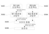
또한, 상기 HUD 영상 생성부는 UV 파장 영역의 2D 이미지를 생성 및 출력하는 제1 UV 프로젝터와 제2 UV 프로젝터를 포함하고, 상기 반사체부는 상기 제1 UV 프로젝터에서 출력되는 UV 파장 영역의 2D 이미지를 가시광선 파장 영역으로 변환하여 굴절시키는 제1 형광체 코팅부; 및 상기 제2 UV 프로젝터에서 출력되는 UV 파장 영역의 2D 이미지를 가시광선 파장 영역으로 변환하여 굴절시키는 제2 형광체 코팅부를 포함하여 이루어지며, 상기 제1 형광체 코팅부 및 상기 제2 형광체 코팅부에서 가시광선 파장 영역으로 변환하여 굴절된 각각의 2D 이미지들의 경로는 운전자의 위치에서 서로 중첩되어 HUD 영상로 제공되는 것을 특징으로 한다.In addition, the HUD image generation unit includes a first UV projector and a second UV projector that generate and output a 2D image of a UV wavelength range, and the reflector unit displays a 2D image of a UV wavelength range output from the first UV projector. A first phosphor coating unit that converts light into a wavelength region and refracts it; and a second phosphor coating unit for converting and refracting a 2D image in a UV wavelength range output from the second UV projector into a visible ray wavelength range, and is visible from the first phosphor coating unit and the second phosphor coating unit. It is characterized in that the paths of each of the 2D images refracted after being converted into the light ray wavelength region are overlapped with each other at the driver's position and provided as a HUD image.
상기와 같은 구성을 통하여 본 발명의 특수 반사체를 활용한 헤드업 디스플레이 시스템은 이하의 특징적인 장점을 제공한다.Through the configuration as described above, the head-up display system using the special reflector of the present invention provides the following characteristic advantages.
1) 종래 기술의 헤드업 디스플레이에서 요구되는 광 경로 변화 및 영상의 확대를 위한 구성요소로서의 최소한 하나 이상의 특수 반사체를 배제하고, 영상을 생성 및 출력하는 디스플레이 소스와 특수 반사체 만으로 HUD 영상을 제공 가능하므로, 전체적인 패키지의 크기를 축소시킬 수 있는 장점이 있다.1) Excluding at least one special reflector as a component for changing the light path and enlarging the image required in the head-up display of the prior art, and providing the HUD image only with the display source and the special reflector that generates and outputs the image. , it has the advantage of being able to reduce the size of the overall package.
2) HUD를 통하여 생성한 2D 영상을 특수 반사체 및 렌즈어레이를 활용하여 3D영상으로 변환하여 투영함으로써, 실제의 3차원 환경에 맞춰 가상의 3D영상을 제공할 수 있으며, 따라서, 2D 영상만을 투영하는 종래 기술보다 시각적으로 자연스러운 HUD 영상을 제공할 수 있는 장점이 있다.2) By converting the 2D image generated through the HUD into a 3D image using a special reflector and lens array and projecting it, it is possible to provide a virtual 3D image according to the actual 3D environment, and thus, only 2D image is projected. There is an advantage in providing a visually natural HUD image compared to the prior art.
도 1은 종래의 헤드업 디스플레이를 나타낸다.
도 2는 본 발명의 제1실시예에 따른 특수 반사체를 활용한 헤드업 디스플레이 시스템을 개략적으로 나타낸다.
도 3은 본 발명의 제1실시예에 따른 특수 반사체를 활용한 헤드업 디스플레이 시스템을 이용한 디스플레이 방법을 나타내는 플로우차트이다.
도 4는 본 발명의 제2실시예에 따른 특수 반사체를 활용한 헤드업 디스플레이 시스템을 개략적으로 나타낸다.
도 5은 본 발명의 제2실시예에 따른 특수 반사체를 활용한 헤드업 디스플레이 시스템을 이용한 디스플레이 방법을 나타내는 플로우차트이다.
도 6는 본 발명의 제3실시예에 따른 특수 반사체를 활용한 헤드업 디스플레이 시스템을 개략적으로 나타낸다.
도 7은 본 발명의 제3실시예에 따른 특수 반사체를 활용한 헤드업 디스플레이 시스템을 이용한 디스플레이 방법을 나타내는 플로우차트이다.
도 8은 본 발명의 제4실시예에 따른 특수 반사체를 활용한 헤드업 디스플레이 시스템을 개략적으로 나타낸다.
도 9는 본 발명의 제4실시예에 따른 특수 반사체를 활용한 헤드업 디스플레이 시스템을 이용한 디스플레이 방법을 나타내는 플로우차트이다.1 shows a conventional head-up display.
2 schematically shows a head-up display system using a special reflector according to a first embodiment of the present invention.
3 is a flowchart showing a display method using a head-up display system using a special reflector according to a first embodiment of the present invention.
4 schematically shows a head-up display system using a special reflector according to a second embodiment of the present invention.
5 is a flowchart showing a display method using a head-up display system using a special reflector according to a second embodiment of the present invention.
6 schematically shows a head-up display system using a special reflector according to a third embodiment of the present invention.
7 is a flowchart illustrating a display method using a head-up display system using a special reflector according to a third embodiment of the present invention.
8 schematically shows a head-up display system using a special reflector according to a fourth embodiment of the present invention.
9 is a flowchart illustrating a display method using a head-up display system using a special reflector according to a fourth embodiment of the present invention.
이하, 본 발명의 기술적 구성을 구체적으로 기술하기에 앞서, 본 명세서 및 특허 청구범위의 전반에 걸쳐 사용된 용어나 단어는 통상적이거나 또는 사전적인 의미로 한정되어 해석되는 것으로 이해해서는 안되며, 해당 용어나 단어는 '발명자는 그 자신의 발명을 가장 최선의 방법으로 설명하기 위해 용어의 개념을 적절하게 정의할 수 있다는 원칙'에 입각하여 기술된 것이며, 본 발명의 기술적 사상에 부합하는 의미와 개념으로 해석되어야 한다. 따라서, 본 명세서에 기재된 실시예와 도면에 도시된 기술 구성은 본 발명의 가장 바람직한 하나의 실시예에 불과하고, 본 발명의 기술적 사상을 모두 대변하는 것은 아니므로, 본 출원시점에 있어서 이들을 대체할 수 있는 다양한 균등물과 변형예들이 있을 수 있음을 이해하여야 한다. 또한, 본 명세서에서 사용된 용어는 특정 실시예를 이해하기 쉽게 설명하기 위한 목적으로 사용되는 것으로, 본 발명을 제한하기 위한 것이 아니다. 본 명세서 상에 단수 형태로 기재된 구성요소는 별도로 특정하는 것이 아니라면 복수의 형태를 포함하는 것으로 이해되어야 한다.Hereinafter, prior to describing the technical configuration of the present invention in detail, terms or words used throughout this specification and claims should not be understood as being construed as being limited to common or dictionary meanings, and the terms or The words are described based on the 'principle that the inventor can appropriately define the concept of terms in order to explain his or her invention in the best way', and be interpreted as meanings and concepts consistent with the technical idea of the present invention. It should be. Therefore, the embodiments described in this specification and the technical configurations shown in the drawings are only one of the most preferred embodiments of the present invention, and do not represent all the technical ideas of the present invention, so they cannot be replaced at the time of this application. It should be understood that there are many possible equivalents and variations. In addition, terms used in this specification are used for the purpose of easily understanding specific embodiments, and are not intended to limit the present invention. Elements described in the singular form on this specification should be understood to include plural forms unless otherwise specified.
본 발명은 종래의 HUD가 가지고 있는 2차원의 정보만을 표시하는 표시방식의 문제 및 패키지의 소형화의 제한 문제를 해결하기 위한 특수 반사체를 활용한 헤드업 디스플레이 시스템에 관한 것으로서, 최소한 하나 이상의 디스플레이 소스,The present invention relates to a head-up display system using a special reflector to solve the problem of a display method displaying only two-dimensional information of a conventional HUD and the limitation problem of miniaturization of a package, and includes at least one display source,
렌즈 및/또는 렌즈 어레이, 및 윈드쉴드에 부착된 특수 반사체부를 이용하여 2D 및 3D 영상을 포함하는 HUD 영상 이미지를 생성 및 투영함으로써, 운전자에게 제공하는 HUD 영상과 실제환경과의 이질감을 해소하고, 더 나아가 HUD 시스템의 패키지의 소형화를 달성하는 기술이다.A HUD image including 2D and 3D images is generated and projected using a lens and/or a lens array and a special reflector attached to the windshield to resolve the sense of difference between the HUD image provided to the driver and the real environment, Furthermore, it is a technology to achieve miniaturization of the package of the HUD system.
이를 위한 본 발명은 HUD 영상 이미지를 생성 및 출력하는 HUD 영상 생성부와, 상기 HUD 영상 생성부로부터 출력되는 빛을 굴절 또는 반사하도록 이루어지되, 상기 HUD 영상 생성부에서 출력되는 HUD 영상의 진행 경로상에 배치되어, 상기 HUD 영상 생성부에서 출력된 특정 파장의 HUD 영상의 진행 경로를 자동차의 운전자의 시야에 도달하도록 굴절 또는 반사하는 반사체부를 포함하여 이루어진다.To this end, the present invention comprises a HUD image generation unit that generates and outputs a HUD image, and refracts or reflects light output from the HUD image generation unit. and a reflector unit that refracts or reflects the traveling path of the HUD image of a specific wavelength output from the HUD image generator to reach the driver's field of view.
이하 첨부된 도면을 참조로 하여 상기와 같은 구성의 본 발명을 바람직한 실시예들을 통하여 상세히 설명하도록 한다.Hereinafter, with reference to the accompanying drawings, the present invention having the above configuration will be described in detail through preferred embodiments.
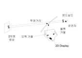
도 2는 본 발명의 제1실시예에 따른 특수 반사체를 활용한 헤드업 디스플레이 시스템을 개략적으로 나타내고, 도 3은 본 발명의 제1실시예에 따른 특수 반사체를 활용한 헤드업 디스플레이 시스템을 이용한 디스플레이 방법을 나타내는 플로우차트이다.2 schematically shows a head-up display system using a special reflector according to a first embodiment of the present invention, and FIG. 3 is a display using a head-up display system using a special reflector according to a first embodiment of the present invention. Here is a flowchart showing how.
상술한 바와 같이, 본 발명은 운전자에게 제공되는 HUD 영상을 생성하기 위한 HUD 영상 생성부(110)와, 상기 HUD 영상 생성부(110)에서 생성되어 출력된 HUD 영상을 굴절 및/또는 반사하여 운전자에게 도달하는 경로를 설정하도록 구비된 반사체부(120)를 포함하여 이루어진다.As described above, the present invention relates to the
상기 HUD 영상 생성부(110)는 운전자에게 제공하기 위한 정보를 포함하는 HUD 영상 이미지를 생성 및 출력 가능하도록 이루어진 구성요소이다.The HUD
본 발명의 제1실시예에서 상기 HUD 영상 생성부(110)는 2D 이미지로 이루어진 기초 이미지를 생성하는 기초 이미지 생성부(111)와 렌즈부(112) 및 렌즈 어레이부(113)를 포함하여 이루어지고, 상기 반사체부(120)는 차량의 윈드실드에 인접하여 내측(차량 실내측)에 배치된 특수 반사체를 포함하여 이루어진다. 여기에서 '특수 반사체'는 상기 HUD 영상 생성부(110)를 통하여 출력되는 HUD 영상을 반사하여 운전자에게 향하도록 영상의 진행 경로를 반사시키는 수단으로서, 반사를 목적으로 이루어진 공지의 어떠한 광학 수단으로도 대체될 수 있는 것으로 이해되어야 한다.In the first embodiment of the present invention, the HUD
상기 렌즈부(112)는 상기 기초 이미지 생성부(111)에서 출력되는 기초 이미지를 왜곡시켜 2D 이미지로 이루어진 가상의 HUD 영상을 생성하고, 상기 렌즈 어레이부(113)는 상기 기초 이미지 생성부(111)에서 출력되는 기초 이미지를 특정 배열로 배열된 다수의 렌즈들을 통하여 왜곡시킴으로써 3D 이미지로 이루어진 가상의 HUD 영상을 생성하도록 이루어진다.The
본 발명의 제1실시예의 HUD 영상 생성부(110)는 기초 이미지 생성부(111)를 통하여 생성된 기초 이미지(2D 형태의)를 상기 렌즈부(112)를 통과시킴으로써 2D로 이루어진 가상의 HUD 영상을 생성하거나, 또는 상기 기초 이미지 생성부(111)를 통하여 생성된 이미지(2D 형태의)를 상기 렌즈 어레이부(113)를 통과시킴으로써 3D로 이루어진 가상의 HUD 영상을 생성하도록 이루어진다.The
상기 렌즈부(112) 및 렌즈 어레이부(113)를 통과하는 기초 이미지는 상기 기초 이미지 생성부(111)의 이미지 출력 위치에 따라 선택적으로 조절될 수 있으며, 상기 렌즈부 및 렌즈 어레이부를 동시에 통과시킴으로써, 2D 및 3D 이미지를 모두 포함하거나, 2D 및 3D 이미지가 겹쳐진 복합 구성의 가상의 HUD 영상을 생성할 수도 있다.The basic image passing through the
상기 렌즈 어레이부(113)를 통과하는 2D 형태의 기초 영상은 예를 들어, 집적영상방식(integral imaging)을 통하여 3D 이미지로 변환될 수 있다. 그러나, 본 발명의 렌즈 어레이부(113)는 상기한 집적영상방식을 적용하는 것으로 한정하는 것은 아니다.The 2D-type basic image passing through the lens array unit 113 may be converted into a 3D image through, for example, integral imaging. However, the lens array unit 113 of the present invention is not limited to applying the integrated imaging method described above.
상기 집적영상방식은 2D 영상을 수많은 렌즈들을 배열하여 만든 렌즈 어레이에 통과시킴으로써 3D로 이루어진 영상을 생성할 수 있는 공지의 기술이다. 상기 집적영상방식을 본 발명에 적용하기 위하여 상기 기초 이미지 생성부(111)에서 출력되는 2D 형태의 기초 이미지는, 최초 취득시에 특정한 렌즈 어레이를 이용하여 기록하고자 하는 영상의 3차원 영상을 이루게 하는 정보(복셀, voxel)를 포함한 기초 이미지(elemental Image)를 포함하여 취득하도록 이루어지고, 상기 기초 이미지를 취득시 사용하였던 렌즈 어레이와 동일한 렌즈 어레이 통하여 상기 기초 이미지를 재생함으로써, 최종적으로 3차원 이미지를 출력하도록 이루어질 수 있다.The integral imaging method is a known technology capable of generating a 3D image by passing a 2D image through a lens array made by arranging numerous lenses. In order to apply the integral imaging method to the present invention, the 2D-type basic image output from the basic
한편, 본 발명의 제1실시예의 반사체부(120)는 상기 HUD 영상 생성부를 통하여 출력된 HUD 영상(2D 및/또는 3D 영상 포함)의 진행 경로를 굴절시켜 운전자에게 진행되도록 하기 위하여 구비되는 구성요소이다.On the other hand, the
상기 반사체부(120)는 운전자의 전방 시야를 가리지 않으면서도 상기 HUD 영상 생성부를 통하여 출력된 영상을 굴절시키기 위한 특수 반사체를 포함하여 이루어진다. 상기 반사체부에 포함되는 특수 반사체는 예를 들어, 투명 거울, 홀로그래픽 광학소자 등을 포함할 수 있으나, 이에 한정하는 것은 아니며, 상기한 바와 같이, 상기 HUD 영상 생성부에서 출력된 영상을 굴절시키되, 운전자의 시야를 방해하지 않은 한 공지의 어떠한 구성요소로도 대체될 수 있는 것으로 이해되어야 한다. The
상기 홀로그래픽 광학소자(HOE, Holographic Optical Element)는 홀로그래픽 기술을 이용하여 특정 파장만 반응하도록 만든 광학소자로서, 보다 상세하게는, 상기 홀로그래픽 광학소자에 신호광선과 참조광선을 간섭을 통해 기록함으로써 특정 파장 영역만을 사용자가 원하는 형태로 반사 또는 굴절이 되도록 하고, 반대로, 특정 파장 이외의 부분은 반응하지 않도록 이루어진 광학소자이다. 따라서, 특정 파장(예를 들어, 470nm, 550nm, 620nm 등)에서 반사되도록 이루어진 홀로그래픽 광학소자에 통상의 빛이 들어가게 된다면, 특정 파장 영역만 반사하고 나머지 파장은 그대로 투과하도록 이루어진다.The Holographic Optical Element (HOE) is an optical element made to react only to a specific wavelength by using holographic technology. More specifically, the holographic optical element records a signal beam and a reference beam through interference. By doing so, only a specific wavelength region is reflected or refracted in a form desired by the user, and conversely, it is an optical element made so that parts other than a specific wavelength do not react. Therefore, if normal light enters the holographic optical element configured to be reflected at a specific wavelength (eg, 470 nm, 550 nm, 620 nm, etc.), only a specific wavelength region is reflected and the remaining wavelengths are transmitted as it is.
이하, 본 발명의 실시예들은 상기 반사체부(120)가 상기와 같은 홀로그래픽 광학소자를 포함하여 이루어지는 것을 기준으로 설명을 전개하도록 하되, 이에 한정되는 것은 아닌 것으로 이해되어야 하며, 본 발명의 기술사상을 벗어나지 않는 한 명세서상에 기술된 기술적 관점을 달성할 수 있는 공지의 어떠한 구성요소로도 대체될 수 있는 것으로 이해되어야 한다.Hereinafter, the embodiments of the present invention will be described based on the fact that the
상기와 같이, 운전자의 전방 시야로부터 들어오는 가시광선은 상기 홀로그래픽 광학소자를 그대로 통과하여 운전자에게 도달하도록 함과 동시에, 상기 HUD 영상 생성부(110)로부터 생성 및 출력된 HUD 영상의 특정 파장만을 굴절 또는 반사시켜 운전자의 눈에 도달하도록 경로를 변경할 수 있다.As described above, the visible light coming from the driver's front sight passes through the holographic optical element as it is to reach the driver, and at the same time refracts only a specific wavelength of the HUD image generated and output from the
상기와 같은 구성의 본 발명의 제1실시예의 특수 반사체를 활용한 헤드업 디스플레이 시스템을 이용한 디스플레이 방법은 이하와 같다.A display method using the head-up display system using the special reflector of the first embodiment of the present invention configured as described above is as follows.
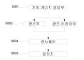
먼저, 상기 HUD 영상 생성부(110)에 포함된 기초 이미지 생성부(111)로부터 기초 이미지(2D로 이루어진)가 생성 및 출력된다(S001).First, a base image (consisting of 2D) is generated and output from the
상기 기초 이미지 생성부(111)에서 출력된 기초 이미지는 상기 기초 이미지 생성부(111)와 인접하여 배치된 렌즈부(112) 또는 렌즈 어레이부(113) 중 최소한 하나 이상을 통과하고, 상기 렌즈부(112) 또는 렌즈 어레이부(113) 중 최소한 하나 이상에 의하여 가상의 2D 및/또는 3D 이미지를 포함하는 HUD 영상으로 변환되어 출력된다(S002).The basic image output from the
상기 렌즈부(112) 또는 렌즈 어레이부(113) 중 하나 이상을 통과하여 출력된 HUD 영상의 진행 경로는 도 2에 도시된 바와 같이 상기 반사체부(120)를 향하여 진행하고, 상기 반사체부(120)에 도달한 HUD 영상은 상기 반사체부(120)에 의하여 그 진행 경로가 운전자의 눈을 향하도록 굴절 또는 반사된다(S003).As shown in FIG. ) is refracted or reflected by the
이때, 상기 반사체부(120)의 홀로그래픽 광학소자에 굴절 또는 반사하도록 설정되지 않은 파장은 상기 반사체부(120)를 그대로 통과하도록 이루어지며, 따라서, 운전자의 전방으로부터 들어오는 가시광선은 상기 반사체부(120)를 그대로 통과하여 운전자에게 도달하고, 이와 동시에, 상기 반사체부(120)에 의하여 진행 경로가 굴절된 HUD 영상 역시 운전자에게 도달하도록 이루어진다(S004). 그 결과 운전자는 전방 시야를 방해받지 않으면서도, 상기 2D 및/또는 3D 형태로 이루어진 가상의 HUD 영상을 볼 수 있게 된다.At this time, wavelengths that are not set to be refracted or reflected by the holographic optical element of the
결과적으로, 운전자는 상기 HUD 영상 생성부(110)로부터 출력된 이미지의 진행 경로(투영거리)만큼 이격된 위치에서 2D 또는 3D 중 하나 이상의 방식(2D, 3D, 2D+3D)으로 이루어진 가상의 HUD 영상을 볼 수 있다.As a result, the driver uses a virtual HUD made of one or more methods (2D, 3D, 2D+3D) of 2D or 3D at a position spaced apart by the traveling path (projection distance) of the image output from the
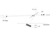
도 4는 본 발명의 제2실시예에 따른 특수 반사체를 활용한 헤드업 디스플레이 시스템을 개략적으로 나타내고, 도 5은 본 발명의 제2실시예에 따른 특수 반사체를 활용한 헤드업 디스플레이 시스템을 이용한 디스플레이 방법을 나타내는 플로우차트이다.4 schematically shows a head-up display system using a special reflector according to a second embodiment of the present invention, and FIG. 5 is a display using a head-up display system using a special reflector according to a second embodiment of the present invention. Here is a flowchart showing how.
본 발명의 제2실시예에서 HUD 영상 생성부(210)는 기초 이미지를 생성하는 기초 이미지 생성부(211)와 렌즈부 및 렌즈 어레이부(212)를 포함하여 이루어지고, 상기 반사체부(220)는 상기 HUD 영상 생성부(210)에서 출력된 HUD 영상이 진행하는 경로상에 위치된 인풋 커플러(221)와 아웃풋 커플러(222)를 포함하여 이루어진다.In the second embodiment of the present invention, the HUD
상기 인풋 커플러(221)와 아웃풋 커플러(222)는 각각 운전자의 전방 시야를 가리지 않으면서도 상기 HUD 영상 생성부(210)를 통하여 출력된 영상을 굴절시키기 위한 특수 반사체를 포함하여 이루어진다. 상기 반사체부(220)에 포함되는 특수 반사체는 예를 들어, 투명 거울, 홀로그래픽 광학소자 등을 포함할 수 있으나, 이에 한정하는 것은 아니며, 상기한 바와 같이, 상기 HUD 영상 생성부(210)에서 출력된 영상을 굴절시키되, 운전자의 시야를 방해하지 않은 한 공지의 어떠한 구성요소로도 대체될 수 있는 것으로 이해되어야 한다.The
또한, 상기 인풋 커플러(221)의 광학특성과 상기 아웃풋 커플러(222)의 광학특성은 서로 동일하거나, 또는 다를 수 있다.Also, the optical characteristics of the
본 발명의 제2실시예의 반사체부(220)는 상기 HUD 영상 생성부(210)에서 출력된 HUD 영상이 진행하는 경로상에 위치된 인풋 커플러(221)와 차량의 윈드실드에 인접하여 배치되는 아웃풋 커플러(222)를 포함하여 이루어지며, 상기 인풋 커플러(221)와 상기 아웃풋 커플러(222)는 특수 반사체를 포함하여 이루어진다. 이때, 상기 인풋 커플러(221)는 특정 파장만 전반사 하도록 이루어지고, 상기 아웃풋 커플러(222)는 특정 파장만을 굴절시키도록 이루어진다.The reflector unit 220 according to the second embodiment of the present invention includes an
따라서, 상기 HUD 영상 생성부(210)에서 출력된 HUD 영상은 도 4에 도시된 바와 같이 윈드실드의 외측(차량 실외측)에 배치된 인풋 커플러(221)에서 특정한 파장만 전반사가 가능한 각도로 반사되고 나머지는 투과시키며, 상기 인풋 커플러(221)에 의하여 전반사로 윈드실드 내부에서 진행하는 HUD 영상은 윈드실드의 내측(차량 실내측)에 배치된 아웃풋 커플러(222)에 도달하여 운전자의 눈 위치로 영상의 진행 경로를 굴절시켜 운전자에게 표시한다.Therefore, as shown in FIG. 4 , the HUD image output from the
상기와 같은 구성의 본 발명의 제2실시예의 특수 반사체를 활용한 헤드업 디스플레이 시스템을 이용한 디스플레이 방법은 이하와 같다.A display method using the head-up display system using the special reflector of the second embodiment of the present invention configured as described above is as follows.
먼저, 상기 HUD 영상 생성부(210)에 포함된 기초 이미지 생성부(211)로부터 2D 형태의 기초 이미지가 생성 및 출력된다(S101).First, a 2D-type base image is generated and output from the
상기 기초 이미지 생성부(211)에서 출력된 기초 이미지는 상기 기초 이미지 생성부와 인접하여 배치된 렌즈부(212) 또는 렌즈 어레이부(213)를 통과하거나, 또는 상기 렌즈부(212) 또는 렌즈 어레이부(213)를 통과하지 않고 직접 출력되도록 이루어질 수 있다.The basic image output from the
다시말해서, 상기 기초 이미지 생성부(211)를 통하여 생성된 기초 이미지(2D 형태의)는 상기 기초 이미지 생성부(211)로부터 출력된 이후, 상기 인풋 커플러(221)로 직접 진행하여 최초 행성된 이미지 그대로 전달되거나, 또는 상기 렌즈부(212)를 통과함으로써 2D 형태로 이루어진 가상의 HUD 영상을 생성하거나 및/또는 상기 기초 이미지 생성부(211)를 통하여 생성된 이미지(2D 형태의)를 상기 렌즈 어레이부(213)를 통과시킴으로써 3D 형태로 이루어진 가상의 HUD 영상을 생성하도록 이루어진다(S102).In other words, the basic image (in 2D form) generated through the basic
상기 렌즈부(212) 및 렌즈 어레이부(213)를 통과하거나 또는 통과하지 않고 직접 전달되는 기초 이미지는 상기 기초 이미지 생성부(211)의 출력 위치에 따라 선택적으로 조절될 수 있으며, 일부가 상기 렌즈부(212) 및 렌즈 어레이부(213) 중 하나 이상을 통과함으로써, 2D 및 3D 이미지가 겹쳐진 가상의 HUD 영상을 생성할 수도 있다.The base image directly transferred with or without passing through the
상기 HUD 영상 생성부로부터 출력된 HUD 영상의 경로는 상기 반사체부(220)를 구성하는 인풋 커플러(221)를 향하여 진행하고, 상기 인풋 커플러(221)에 도달한 HUD 영상은 상기 인풋 커플러(221)에서 특정한 파장(상기 HUD 이미지의 파장)만 전반사되고, 상기 인풋 커플러(221)의 홀로그래픽 광학소자에서 전반사 하도록 설정되지 않은 파장은 상기 인풋 커플러(221)를 그대로 통과하도록 이루어진다(S103).The path of the HUD image output from the HUD image generator proceeds toward the
상기 인풋 커플러(221)의 홀로그래픽 광학소자에서 전반사된 HUD 영상은 상기 윈드쉴드 내에서 전반사로 진행하여 상기 반사체부(220)를 구성하는 아웃풋 커플러(222)에 도달하고, 상기 HUD 영상은 상기 아웃풋 커플러(222)를 통과하여 운전자의 위치로 진행 경로가 굴절된다(S104). 이때, 상기 아웃풋 커플러(222)의 홀로그래픽 광학소자에 굴절 또는 반사하도록 설정되지 않은 파장은 상기 반사체부(220)를 그대로 통과하도록 이루어지며, 따라서, 운전자의 전방으로부터 들어오는 가시광선은 상기 아웃풋 커플러(222)의 홀로그래픽 광학소자를 그대로 통과하여 운전자에게 도달하도록 이루어진다.The HUD image totally reflected by the holographic optical element of the
결과적으로, 운전자는 전방 시야를 방해받지 않으면서도 상기 HUD 영상 생성부(210)로부터 출력된 HUD 영상의 진행 경로(투영거리)만큼 이격된 위치에서 HUD 영상을 볼 수 있다(S005).As a result, the driver can view the HUD image from a position separated by the traveling path (projection distance) of the HUD image output from the
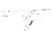
본 발명의 제2실시예의 변형 예로서, 상기 인풋 커플러가 윈드실드의 내측에 배치된 실시예(미도시)도 고려될 수 있다. 이 실시예의 HUD 영상 생성부(210')와 반사체부(220')는 상기 제2실시예의 기술 구성과 동일한 구성으로 이루어지나, 상기 반사체부(220')의 인풋 커플러(221')는 홀로그래픽 광학 소자로 이루지되, HUD 영상을 통과하도록 이루어진다. 결과적으로, 이 실시예의 인풋 커플러(221')를 통과한 HUD 영상 역시 윈드실드 내부에서 전반사하며 진행하도록 이루어진다.As a modified example of the second embodiment of the present invention, an embodiment (not shown) in which the input coupler is disposed inside the windshield may also be considered. The HUD image generating unit 210' and the reflector unit 220' of this embodiment have the same technical configuration as that of the second embodiment, but the input coupler 221' of the reflector unit 220' is holographic. It consists of an optical element, but is made to pass through the HUD image. As a result, the HUD image passing through the input coupler 221' of this embodiment is also made to proceed with total reflection inside the windshield.
도 7은 본 발명의 제3실시예에 따른 특수 반사체를 활용한 헤드업 디스플레이 시스템을 개략적으로 나타내고, 도 8은 본 발명의 제3실시예에 따른 특수 반사체를 활용한 헤드업 디스플레이 시스템을 이용한 디스플레이 방법을 나타내는 플로우차트이다.7 schematically shows a head-up display system using a special reflector according to a third embodiment of the present invention, and FIG. 8 is a display using a head-up display system using a special reflector according to a third embodiment of the present invention. Here is a flowchart showing how.
본 발명의 제3실시예에서 HUD 영상 생성부(310)는 UV 파장 영역의 2D 이미지를 생성하여 출력하는 UV 프로젝터(311)와 렌즈 어레이(312)를 포함하여 이루어지고, 상기 반사체부(320)는 상기 HUD 영상 생성부(310)에서 출력된 UV 파장 영역의 2D 이미지를 가시광선 파장 영역의 기초 이미지로 변환하는 형광체 코팅부를 포함하여 이루어진다. 이때, 상기 HUD 영상 생성부(310)의 렌즈 어레이(312)는 윈드실드의 내측(차량 실내측)에 배치되고, 상기 반사체부(320)의 형광체 코팅부는 윈드실드의 외측(차량 실외측)에 배치된다.In the third embodiment of the present invention, the HUD
본 발명의 제3실시예의 HUD 영상 생성부(310)를 통하여 UV 파장 영역의 2D 이미지로 이루어진 기초 이미지가 상기 UV 프로젝터(311)로부터 출력되면, 해당 이미지는 UV 파장으로 이루어지기 때문에 상기 렌즈 어레이(312)를 그대로 통과하고, 이후, 상기 형광체 코팅부를 통하여 가시광선 파장 영역으로 변환되어 굴절 진행하는 기초 이미지는 상기 렌즈 어레이(312)를 다시 통과하며 HUD 영상로 전환된다.When a basic image consisting of a 2D image in the UV wavelength region is output from the
본 발명의 제3실시예의 반사체부(320)는 UV 파장이 도달하면 가시광선 영역의 파장으로 변환되는 형광체를 코팅한 형광체 코팅부를 포함하여 이루어진다. 따라서, 상기 형광체 코팅부에 상기 HUD 영상 생성부(310)에서 출력된 UV 파장 영역의 2D 이미지가 도달하면, 해당 이미지는 가시광선 파장 영역으로 변환되어 굴절되도록 이루어진다.The
상기와 같은 구성의 본 발명의 제3실시예의 특수 반사체를 활용한 헤드업 디스플레이 시스템을 이용한 디스플레이 방법은 이하와 같다.A display method using the head-up display system using the special reflector of the third embodiment of the present invention configured as described above is as follows.
먼저, 상기 HUD 영상 생성부에 포함된 UV 프로젝터로부터 UV 파장 영역의 2D 기초 이미지가 생성 및 출력된다(S201).First, a 2D basic image in the UV wavelength region is generated and output from the UV projector included in the HUD image generation unit (S201).
상기 UV 프로젝터에서 출력된 UV 파장 영역의 2D 기초 이미지는 윈드실드의 내측에 배치된 상기 렌즈 어레이를 통과하여 상기 윈드실드의 외측에 배치된 형광체 코팅부에 반사되며, 가시광선 파장 영역의 2D 기초 이미지로 변환된다(S202).The 2D basic image in the UV wavelength range output from the UV projector passes through the lens array disposed inside the windshield and is reflected on the phosphor coating unit disposed outside the windshield, and the 2D basic image in the visible ray wavelength range is converted to (S202).
상기 형광체 코팅부에서 반사되어 진행하는 가시광선 파장 영역의 2D 기초 이미지의 경로는 상기 렌즈 어레이를 향하여 진행하고, 상기 렌즈 어레이에 도달한 가시광선 파장 영역의 2D 기초 이미지는 상기 렌즈 어레이를 통과하며 HUD 영상로 변환되고, 상기 HUD 영상의 진행경로는 운전자의 위치로 진행된다(S203).The path of the 2D basic image in the visible ray wavelength region that is reflected from the phosphor coating part travels toward the lens array, and the 2D basic image in the visible ray wavelength region that reaches the lens array passes through the lens array and displays the HUD It is converted into an image, and the traveling path of the HUD image proceeds to the driver's position (S203).
결과적으로, 운전자는 전방 시야를 방해받지 않으면서도 상기 HUD 영상 생성부로부터 출력된 이미지의 진행 경로(투영거리)만큼 이격된 위치에서 집적 영상 방식으로 생성된 HUD 영상로 이루어진 영상정보를 획득할 수 있다(S204).As a result, the driver can obtain image information composed of the HUD image generated by the integrated image method at a location spaced apart by the traveling path (projection distance) of the image output from the HUD image generator without obstructing the forward view. (S204).
도 8은 본 발명의 제4실시예에 따른 특수 반사체를 활용한 헤드업 디스플레이 시스템을 개략적으로 나타내고, 도 9는 본 발명의 제4실시예에 따른 특수 반사체를 활용한 헤드업 디스플레이 시스템을 이용한 디스플레이 방법을 나타내는 플로우차트이다.8 schematically shows a head-up display system using a special reflector according to a fourth embodiment of the present invention, and FIG. 9 is a display using a head-up display system using a special reflector according to a fourth embodiment of the present invention. Here is a flowchart showing how.
본 발명의 제4실시예에서 HUD 영상 생성부(410)는 UV 파장 영역의 2D 이미지를 각각 생성하여 출력하는 제1 UV 프로젝터(411) 및 제2 UV 프로젝터(412)를 포함하여 이루어지고, 상기 반사체부(420)는 상기 HUD 영상 생성부의 제1 UV 프로젝터(411) 및 제2 UV 프로젝터(412)에서 각각 출력된 각각의 UV 파장 영역의 2D 이미지를 가시광선 파장 영역의 기초 이미지로 각각 변환하는 제1 형광체 코팅부(421) 및 제2 형광체 코팅부(422)를 포함하여 이루어진다. 이때, 도시된 바와 같이, 상기 제1 형광체 코팅부(421)는 윈드실드의 외측(차량 실외측)에 배치되고, 상기 제2 형광체 코팅부(422)는 윈드실드의 내측(차량 실내측)에 배치된다.In the fourth embodiment of the present invention, the HUD
본 발명의 제4실시예의 HUD 영상 생성부(410)를 통하여 UV 파장 영역의 2D 이미지로 이루어진 두개의 2D 기초 이미지(UV1, UV2)가 상기 제1 UV 프로젝터(411) 및 제2 UV 프로젝터(412)로부터 각각 출력되면, 해당 이미지들은 각각에 대응하도록 이루어진 상기 제1 형광체 코팅부(421) 및 제2 형광체 코팅부(422)에 각각 도달하여 가시광선 파장 영역으로 각각 변환되어 굴절 진행하게 되고, 가시광선 파장 영역으로 변환되어 진행하는 두개의 2D 기초 이미지(UV1, UV2)는 운전자의 위치에서 중첩된 영상으로 보여지게 되어 3차원 영상정보로서 제공된다.The
상기와 같은 구성의 본 발명의 제4실시예의 특수 반사체를 활용한 헤드업 디스플레이 시스템을 이용한 디스플레이 방법은 이하와 같다.A display method using the head-up display system using the special reflector of the fourth embodiment of the present invention configured as described above is as follows.
먼저, 상기 HUD 영상 생성부에 포함된 제1 UV 프로젝터로부터 UV 파장 영역의 2D 기초 이미지(UV1)가 생성 및 출력된다(S301).First, a 2D basic image UV1 in the UV wavelength region is generated and output from the first UV projector included in the HUD image generation unit (S301).
상기 제1 UV 프로젝터에서 출력된 UV 파장 영역의 2D 기초 이미지(UV1)는 윈드실드의 외측에 배치된 제1 형광체 코팅부에 반사되며, 가시광선 파장 영역의 2D 기초 이미지로 변환된다(S302).The 2D basic image UV1 in the UV wavelength region output from the first UV projector is reflected on the first phosphor coating part disposed outside the windshield and converted into a 2D basic image in the visible ray wavelength region (S302).
상기 단계 S301과 동시에, 상기 HUD 영상 생성부에 포함된 제2 UV 프로젝터로부터 UV 파장 영역의 2D 기초 이미지(UV2)가 생성 및 출력된다(S303).Simultaneously with the step S301, a 2D basic image UV2 in the UV wavelength region is generated and output from the second UV projector included in the HUD image generating unit (S303).
상기 제2 UV 프로젝터에서 출력된 UV 파장 영역의 2D 기초 이미지(UV2)는 윈드실드의 내측에 배치된 제2 형광체 코팅부에 반사되며, 가시광선 파장 영역의 2D 기초 이미지로 변환된다(S304).The 2D basic image UV2 of the UV wavelength region output from the second UV projector is reflected on the second phosphor coating part disposed inside the windshield, and is converted into a 2D basic image of the visible ray wavelength region (S304).
상기 단계 S302 및 S304에서 가시광선 파장 영역으로 변환되어 굴절 진행하는 각각의 기초 이미지들의 진행경로는 운전자의 위치로 진행되며, 운전자의 위치에서 서로 중첩되도록 이루어진다(S305).In steps S302 and S304, the respective basic images converted to the visible ray wavelength region and refracted proceed to the driver's position, and overlap each other at the driver's position (S305).
결과적으로, 운전자는 전방 시야를 방해받지 않으면서도 상기 HUD 영상 생성부로부터 출력된 이미지의 진행 경로(투영거리)만큼 이격된 위치에서 두개의 2D 기초 이미지의 중첩된 이미지로 영상정보를 획득할 수 있다(S306).As a result, the driver can acquire image information as an overlapping image of two 2D basic images at a position spaced apart by the traveling path (projection distance) of the image output from the HUD image generator without obstructing the forward view. (S306).
상기 제1 내지 제4 실시예의 기술 구성과 같이, 본 발명의 특수 반사체를 활용한 헤드업 디스플레이 시스템은 HUD 영상을 생성하기 위한 HUD 영상 생성부와, 상기 HUD 영상 생성부에서 생성되어 출력된 HUD 영상을 굴절 및/또는 반사하여 운전자에게 도달하는 경로를 설정하도록 구비된 반사체부를 통하여, 운전자에게 HUD 영상로 이루어진 헤드업 디스플레이를 제공할 수 있으며,Like the technical configuration of the first to fourth embodiments, the head-up display system using the special reflector of the present invention includes a HUD image generating unit for generating a HUD image, and a HUD image generated and output by the HUD image generating unit. A head-up display consisting of a HUD image may be provided to the driver through a reflector unit provided to set a path to reach the driver by refracting and/or reflecting the
이러한 기술 구성은, 헤드업 디스플레이를 통하여 제공되는 영상정보 내의 각각의 컨텐츠의 투영거리를 개별적으로 제어 가능하게 하고 있으며, 전체적인 헤드업 디스플레이의 효용성을 증가 시키는 장점을 제공한다.This technical configuration makes it possible to individually control the projection distance of each content in the image information provided through the head-up display, and provides an advantage of increasing the effectiveness of the overall head-up display.
더 나아가, 본 발명의 상기와 같은 기술 구성을 통하여 종래 기술의 헤드업 디스플레이에서 요구되는 광 경로 변화 및 영상의 확대를 위한 구성요소로서의 볼록거울 및 오목거울 등을 배제하고, 영상을 생성 및 출력하는 디스플레이 소스와 특수 반사체 만으로 3D 영상을 제공 가능하므로, 전체적인 패키지의 크기를 감소시키는 장점을 제공한다.Furthermore, through the above technical configuration of the present invention, convex mirrors and concave mirrors as components for changing the light path and enlarging the image required in the head-up display of the prior art are excluded, and the image is generated and output Since 3D images can be provided only with a display source and a special reflector, it provides an advantage of reducing the size of the overall package.
이상으로 본 발명의 특수 반사체를 활용한 헤드업 디스플레이 시스템의 바람직한 실시예를 상세하게 설명하였으나, 이는 본 발명에 대한 이해를 돕기 위하여 특정한 예를 제시한 것에 지나지 않으며, 본 발명의 범위를 한정하고자 하는 것은 아니다. 여기에 개시된 실시예들 이외에도, 본 발명의 기술적 사상에 바탕을 둔 다른 변형예들이 실시 가능하다는 것은 본 고안이 속하는 기술분야에서 통상의 지식을 가진 자에게 자명한 것이다.Although the preferred embodiment of the head-up display system using the special reflector of the present invention has been described in detail above, this is only presented as a specific example to help understanding of the present invention, and is intended to limit the scope of the present invention. It is not. In addition to the embodiments disclosed herein, it is obvious to those skilled in the art that other modifications based on the technical idea of the present invention can be implemented.
110: 제1실시예의 HUD 영상 생성부
111: 제1실시예의 기초 이미지 생성부
112: 제1실시예의 렌즈부
113: 제1실시예의 렌즈 어레이부
120: 제1실시예의 반사체부
210: 제2실시예의 HUD 영상 생성부
211: 제2실시예의 기초 이미지 생성부
212: 제2실시예의 렌즈부
213: 제2실시예의 렌즈 어레이부
220: 제2실시예의 반사체부
221: 제2실시예의 인풋 커플러
222: 제2실시예의 아웃풋 커플러
310: 제3실시예의 HUD 영상 생성부
311: 제3실시예의 UV 프로젝터
312: 제3실시예의 렌즈 어레이
320: 제3실시예의 반사체부
410: 제4실시예의 HUD 영상 생성부
411: 제4실시예의 제1 UV 프로젝터
412: 제4실시예의 제2 UV 프로젝터
420: 제4실시예의 반사체부
421: 제4실시예의 제1 형광체 코팅부
422: 제4실시예의 제2 형광체 코팅부110: HUD image generator of the first embodiment
111: basic image generator of the first embodiment
112: lens unit of the first embodiment
113: lens array unit of the first embodiment
120: reflector unit of the first embodiment
210: HUD image generator of the second embodiment
211: basic image generation unit of the second embodiment
212: lens unit of the second embodiment
213: lens array unit of the second embodiment
220: reflector unit of the second embodiment
221: input coupler of the second embodiment
222: output coupler of the second embodiment
310: HUD image generator of the third embodiment
311: UV projector of the third embodiment
312: lens array of the third embodiment
320: reflector unit of the third embodiment
410: HUD image generator of the fourth embodiment
411 First UV projector of the fourth embodiment
412: second UV projector of the fourth embodiment
420: reflector unit of the fourth embodiment
421: first phosphor coating part of the fourth embodiment
422: second phosphor coating part of the fourth embodiment
Claims (7)
Translated fromKorean특정 파장 영역으로 이루어지는 HUD 영상을 생성 및 출력하는 HUD 영상 생성부; 및
특정 파장 영역만을 굴절 또는 반사하도록 이루어지되, 상기 HUD 영상 생성부에서 출력되는 HUD 영상의 경로상에 배치되어, 상기 HUD 영상 생성부에서 출력된 특정 파장 영역의 HUD 영상의 경로를 자동차의 운전자의 시야에 도달하도록 굴절 또는 반사하는 반사체부;를 포함하고,
상기 반사체부는 홀로그래픽 광학소자를 포함하되,
상기 HUD 영상 생성부에서 출력되는 특정 파장 영역의 HUD 영상을 전반사시키는 인풋커플러; 및 상기 인풋커플러에서 전반사된 특정 파장 영역의 HUD 영상을 굴절시키는 아웃풋커플러를 포함하여 이루어지고,
상기 인풋커플러는 자동차의 윈드실드의 외측에 배치되고,
상기 아웃풋 커플러는 자동차의 윈드실드의 내측에 배치되며,
상기 인풋커플러에서 전반사된 특정 파장 영역의 HUD 영상은 상기 윈드실드 내에서 전반사되며 상기 아웃풋커플러로 진행하도록 이루어지는 것을 특징으로 하는 특수 반사체를 활용한 헤드업 디스플레이 시스템.
In the head-up display system using a special reflector applied to automobiles,
a HUD image generating unit generating and outputting a HUD image consisting of a specific wavelength region; and
It is made to refract or reflect only a specific wavelength region, but is arranged on the path of the HUD image output from the HUD image generator, and the path of the HUD image of the specific wavelength region output from the HUD image generator is changed to the driver's field of view. It includes; a reflector unit that refracts or reflects to reach
The reflector unit includes a holographic optical element,
an input coupler that totally reflects the HUD image of a specific wavelength region output from the HUD image generating unit; and an output coupler that refracts the HUD image of a specific wavelength region totally reflected by the input coupler,
The input coupler is disposed outside the windshield of the vehicle,
The output coupler is disposed inside the windshield of the vehicle,
The head-up display system using a special reflector, characterized in that the HUD image of a specific wavelength region totally reflected by the input coupler is totally reflected in the windshield and proceeds to the output coupler.
상기 HUD 영상 생성부는 2D 이미지로 이루어진 기초 이미지를 생성 및 출력하는 기초 이미지 생성부;
상기 기초 이미지 생성부에서 출력되는 기초 이미지를 왜곡시켜 2D 이미지로 이루어진 가상의 HUD 영상을 생성하는 렌즈부; 및
상기 기초 이미지 생성부에서 출력되는 기초 이미지를 왜곡시켜 3D 이미지로 이루어진 가상의 HUD 영상을 생성하는 렌즈 어레이부;
를 포함하는 것을 특징으로 하는 특수 반사체를 활용한 헤드업 디스플레이 시스템.
According to claim 1,
The HUD image generating unit includes a basic image generating unit generating and outputting a basic image made of a 2D image;
a lens unit generating a virtual HUD image composed of 2D images by distorting the basic image output from the basic image generating unit; and
a lens array unit generating a virtual HUD image composed of 3D images by distorting the basic image output from the basic image generating unit;
Head-up display system using a special reflector comprising a.
상기 반사체부는 상기 HUD 영상 생성부에서 출력되는 HUD 영상의 특정 파장 영역만을 굴절 또는 반사시키는 홀로그래픽 광학소자를 포함하여 이루어지는 것을 특징으로 하는 특수 반사체를 활용한 헤드업 디스플레이 시스템.
According to claim 1,
The head-up display system using a special reflector, characterized in that the reflector unit includes a holographic optical element that refracts or reflects only a specific wavelength region of the HUD image output from the HUD image generator.
상기 HUD 영상 생성부는 UV 파장 영역의 2D 이미지를 생성 및 출력하는 UV 프로젝터와 렌즈 어레이를 포함하고,
상기 반사체부는 상기 UV 프로젝터에서 출력되는 UV 파장 영역의 2D 이미지를 가시광선 파장 영역으로 변환하여 굴절시키는 형광체 코팅부를 포함하여 이루어지며,
상기 반사체부에서 가시광선 파장 영역으로 변환하여 굴절된 2D 이미지는 상기 렌즈 어레이를 통과하여 HUD 영상로 변환 출력되는 것을 특징으로 하는 특수 반사체를 활용한 헤드업 디스플레이 시스템.
According to claim 1,
The HUD image generating unit includes a UV projector and a lens array that generate and output a 2D image in a UV wavelength region,
The reflector unit includes a phosphor coating unit for converting and refracting a 2D image of a UV wavelength range output from the UV projector into a visible ray wavelength range,
The head-up display system using a special reflector, characterized in that the 2D image converted to the visible ray wavelength region and refracted by the reflector unit passes through the lens array and is converted and output as a HUD image.
상기 HUD 영상 생성부는 UV 파장 영역의 2D 이미지를 생성 및 출력하는 제1 UV 프로젝터와 제2 UV 프로젝터를 포함하고,
상기 반사체부는 상기 제1 UV 프로젝터에서 출력되는 UV 파장 영역의 2D 이미지를 가시광선 파장 영역으로 변환하여 굴절시키는 제1 형광체 코팅부; 및 상기 제2 UV 프로젝터에서 출력되는 UV 파장 영역의 2D 이미지를 가시광선 파장 영역으로 변환하여 굴절시키는 제2 형광체 코팅부를 포함하여 이루어지며,
상기 제1 형광체 코팅부 및 상기 제2 형광체 코팅부에서 가시광선 파장 영역으로 변환하여 굴절된 각각의 2D 이미지들의 경로는 운전자의 위치에서 서로 중첩되어 HUD 영상로 제공되는 것을 특징으로 하는 특수 반사체를 활용한 헤드업 디스플레이 시스템.According to claim 1,
The HUD image generating unit includes a first UV projector and a second UV projector that generate and output a 2D image in a UV wavelength region,
The reflector unit may include a first phosphor coating unit that converts and refracts the 2D image of the UV wavelength range output from the first UV projector into the visible ray wavelength range; and a second phosphor coating unit for converting and refracting the 2D image in the UV wavelength range output from the second UV projector into the visible ray wavelength range,
Utilizing a special reflector, characterized in that the paths of each of the 2D images refracted by converting to the visible light wavelength region in the first phosphor coating unit and the second phosphor coating unit are overlapped with each other at the driver's position and provided as a HUD image A heads-up display system.
Priority Applications (1)
| Application Number | Priority Date | Filing Date | Title |
|---|---|---|---|
| KR1020160172949AKR102521482B1 (en) | 2016-12-16 | 2016-12-16 | Head Up Display System With Special Reflector |
Applications Claiming Priority (1)
| Application Number | Priority Date | Filing Date | Title |
|---|---|---|---|
| KR1020160172949AKR102521482B1 (en) | 2016-12-16 | 2016-12-16 | Head Up Display System With Special Reflector |
Publications (2)
| Publication Number | Publication Date |
|---|---|
| KR20180070351A KR20180070351A (en) | 2018-06-26 |
| KR102521482B1true KR102521482B1 (en) | 2023-04-14 |
Family
ID=62788817
Family Applications (1)
| Application Number | Title | Priority Date | Filing Date |
|---|---|---|---|
| KR1020160172949AActiveKR102521482B1 (en) | 2016-12-16 | 2016-12-16 | Head Up Display System With Special Reflector |
Country Status (1)
| Country | Link |
|---|---|
| KR (1) | KR102521482B1 (en) |
Families Citing this family (3)
| Publication number | Priority date | Publication date | Assignee | Title |
|---|---|---|---|---|
| CN112578612B (en)* | 2019-09-30 | 2022-03-22 | 宁波舜宇车载光学技术有限公司 | Vehicle lamp system and assembling method thereof |
| KR20250048791A (en)* | 2022-09-19 | 2025-04-10 | 베이징 지티아오 네트워크 테크놀로지 컴퍼니, 리미티드 | Human-computer interaction methods, display methods, apparatus and devices |
| EP4597201A1 (en)* | 2022-12-01 | 2025-08-06 | LG Electronics Inc. | Head-up display |
Citations (4)
| Publication number | Priority date | Publication date | Assignee | Title |
|---|---|---|---|---|
| KR100611992B1 (en) | 2004-10-21 | 2006-08-11 | 삼성전자주식회사 | 3D video display device |
| JP2011090076A (en) | 2009-10-21 | 2011-05-06 | Panasonic Corp | Image display device |
| JP2013047698A (en) | 2009-12-21 | 2013-03-07 | Nippon Sheet Glass Co Ltd | Lens optical system, image display apparatus, and head-up display |
| JP2016206316A (en) | 2015-04-17 | 2016-12-08 | リコーインダストリアルソリューションズ株式会社 | Screen and display |
Family Cites Families (3)
| Publication number | Priority date | Publication date | Assignee | Title |
|---|---|---|---|---|
| JP3418985B2 (en)* | 1992-12-14 | 2003-06-23 | 株式会社デンソー | Image display device |
| FR2929016B1 (en)* | 2008-03-19 | 2010-06-04 | Saint Gobain | HEAD VISUALIZATION DEVICE. |
| KR102071693B1 (en)* | 2014-02-07 | 2020-01-30 | 엘지전자 주식회사 | Head-Up Display Apparatus |
- 2016
- 2016-12-16KRKR1020160172949Apatent/KR102521482B1/enactiveActive
Patent Citations (4)
| Publication number | Priority date | Publication date | Assignee | Title |
|---|---|---|---|---|
| KR100611992B1 (en) | 2004-10-21 | 2006-08-11 | 삼성전자주식회사 | 3D video display device |
| JP2011090076A (en) | 2009-10-21 | 2011-05-06 | Panasonic Corp | Image display device |
| JP2013047698A (en) | 2009-12-21 | 2013-03-07 | Nippon Sheet Glass Co Ltd | Lens optical system, image display apparatus, and head-up display |
| JP2016206316A (en) | 2015-04-17 | 2016-12-08 | リコーインダストリアルソリューションズ株式会社 | Screen and display |
Also Published As
| Publication number | Publication date |
|---|---|
| KR20180070351A (en) | 2018-06-26 |
Similar Documents
| Publication | Publication Date | Title |
|---|---|---|
| US11128847B2 (en) | Information display device and information display method | |
| JP6473895B2 (en) | Head-up display and mobile body equipped with head-up display | |
| JP6603883B2 (en) | Head-up display and mobile body equipped with head-up display | |
| KR102397089B1 (en) | Method of processing images and apparatus thereof | |
| JP6601431B2 (en) | Head-up display device | |
| WO2015159523A1 (en) | Heads-up display and moving body equipped with heads-up display | |
| WO2018061444A1 (en) | Reflection plate, information display device, and movable body | |
| KR20190072649A (en) | Virtual image display device | |
| JP7584828B2 (en) | A multiple viewing angle monitor system capable of magnified diffraction reflection | |
| WO2017138431A1 (en) | Display device and head-up display | |
| KR20190071005A (en) | Virtual image display device | |
| KR102521482B1 (en) | Head Up Display System With Special Reflector | |
| JP6793372B2 (en) | Retinal projection device, retinal projection system | |
| JP6593461B2 (en) | Virtual image display device | |
| CN113661432B (en) | HUD | |
| JP6593462B2 (en) | Virtual image display device | |
| JP6593464B2 (en) | Virtual image display device | |
| CN112219151A (en) | Device for generating virtual images with apertures associated with field points | |
| JP7111070B2 (en) | head-up display device | |
| JP7111071B2 (en) | head-up display device | |
| KR20190059991A (en) | Virtual image display device | |
| JP6593465B2 (en) | Virtual image display device | |
| JP2017207632A (en) | Projection type display device and head-up display | |
| US12105291B2 (en) | Projection device for smart glasses, method for representing image information, using a projection device, and control unit | |
| US12352968B2 (en) | Waveguide for angular space light modulator display |
Legal Events
| Date | Code | Title | Description |
|---|---|---|---|
| PA0109 | Patent application | Patent event code:PA01091R01D Comment text:Patent Application Patent event date:20161216 | |
| PG1501 | Laying open of application | ||
| A201 | Request for examination | ||
| PA0201 | Request for examination | Patent event code:PA02012R01D Patent event date:20201201 Comment text:Request for Examination of Application Patent event code:PA02011R01I Patent event date:20161216 Comment text:Patent Application | |
| PE0902 | Notice of grounds for rejection | Comment text:Notification of reason for refusal Patent event date:20220921 Patent event code:PE09021S01D | |
| E701 | Decision to grant or registration of patent right | ||
| PE0701 | Decision of registration | Patent event code:PE07011S01D Comment text:Decision to Grant Registration Patent event date:20230310 | |
| GRNT | Written decision to grant | ||
| PR0701 | Registration of establishment | Comment text:Registration of Establishment Patent event date:20230410 Patent event code:PR07011E01D | |
| PR1002 | Payment of registration fee | Payment date:20230411 End annual number:3 Start annual number:1 | |
| PG1601 | Publication of registration |