KR102521298B1 - Memory controller and operating method thereof - Google Patents
Memory controller and operating method thereofDownload PDFInfo
- Publication number
- KR102521298B1 KR102521298B1KR1020180018291AKR20180018291AKR102521298B1KR 102521298 B1KR102521298 B1KR 102521298B1KR 1020180018291 AKR1020180018291 AKR 1020180018291AKR 20180018291 AKR20180018291 AKR 20180018291AKR 102521298 B1KR102521298 B1KR 102521298B1
- Authority
- KR
- South Korea
- Prior art keywords
- capacity
- buffer unit
- buffer
- unit
- threshold
- Prior art date
- Legal status (The legal status is an assumption and is not a legal conclusion. Google has not performed a legal analysis and makes no representation as to the accuracy of the status listed.)
- Active
Links
Images


Classifications
- G—PHYSICS
- G06—COMPUTING OR CALCULATING; COUNTING
- G06F—ELECTRIC DIGITAL DATA PROCESSING
- G06F3/00—Input arrangements for transferring data to be processed into a form capable of being handled by the computer; Output arrangements for transferring data from processing unit to output unit, e.g. interface arrangements
- G06F3/06—Digital input from, or digital output to, record carriers, e.g. RAID, emulated record carriers or networked record carriers
- G06F3/0601—Interfaces specially adapted for storage systems
- G06F3/0668—Interfaces specially adapted for storage systems adopting a particular infrastructure
- G06F3/0671—In-line storage system
- G06F3/0673—Single storage device
- G—PHYSICS
- G06—COMPUTING OR CALCULATING; COUNTING
- G06F—ELECTRIC DIGITAL DATA PROCESSING
- G06F12/00—Accessing, addressing or allocating within memory systems or architectures
- G06F12/02—Addressing or allocation; Relocation
- G06F12/0223—User address space allocation, e.g. contiguous or non contiguous base addressing
- G06F12/023—Free address space management
- G06F12/0238—Memory management in non-volatile memory, e.g. resistive RAM or ferroelectric memory
- G06F12/0246—Memory management in non-volatile memory, e.g. resistive RAM or ferroelectric memory in block erasable memory, e.g. flash memory
- G—PHYSICS
- G06—COMPUTING OR CALCULATING; COUNTING
- G06F—ELECTRIC DIGITAL DATA PROCESSING
- G06F12/00—Accessing, addressing or allocating within memory systems or architectures
- G06F12/02—Addressing or allocation; Relocation
- G06F12/08—Addressing or allocation; Relocation in hierarchically structured memory systems, e.g. virtual memory systems
- G06F12/0802—Addressing of a memory level in which the access to the desired data or data block requires associative addressing means, e.g. caches
- G06F12/0866—Addressing of a memory level in which the access to the desired data or data block requires associative addressing means, e.g. caches for peripheral storage systems, e.g. disk cache
- G—PHYSICS
- G06—COMPUTING OR CALCULATING; COUNTING
- G06F—ELECTRIC DIGITAL DATA PROCESSING
- G06F12/00—Accessing, addressing or allocating within memory systems or architectures
- G06F12/02—Addressing or allocation; Relocation
- G06F12/08—Addressing or allocation; Relocation in hierarchically structured memory systems, e.g. virtual memory systems
- G06F12/0802—Addressing of a memory level in which the access to the desired data or data block requires associative addressing means, e.g. caches
- G06F12/0893—Caches characterised by their organisation or structure
- G06F12/0895—Caches characterised by their organisation or structure of parts of caches, e.g. directory or tag array
- G—PHYSICS
- G06—COMPUTING OR CALCULATING; COUNTING
- G06F—ELECTRIC DIGITAL DATA PROCESSING
- G06F13/00—Interconnection of, or transfer of information or other signals between, memories, input/output devices or central processing units
- G06F13/14—Handling requests for interconnection or transfer
- G06F13/16—Handling requests for interconnection or transfer for access to memory bus
- G06F13/1668—Details of memory controller
- G06F13/1673—Details of memory controller using buffers
- G—PHYSICS
- G06—COMPUTING OR CALCULATING; COUNTING
- G06F—ELECTRIC DIGITAL DATA PROCESSING
- G06F3/00—Input arrangements for transferring data to be processed into a form capable of being handled by the computer; Output arrangements for transferring data from processing unit to output unit, e.g. interface arrangements
- G06F3/06—Digital input from, or digital output to, record carriers, e.g. RAID, emulated record carriers or networked record carriers
- G06F3/0601—Interfaces specially adapted for storage systems
- G06F3/0602—Interfaces specially adapted for storage systems specifically adapted to achieve a particular effect
- G06F3/061—Improving I/O performance
- G—PHYSICS
- G06—COMPUTING OR CALCULATING; COUNTING
- G06F—ELECTRIC DIGITAL DATA PROCESSING
- G06F3/00—Input arrangements for transferring data to be processed into a form capable of being handled by the computer; Output arrangements for transferring data from processing unit to output unit, e.g. interface arrangements
- G06F3/06—Digital input from, or digital output to, record carriers, e.g. RAID, emulated record carriers or networked record carriers
- G06F3/0601—Interfaces specially adapted for storage systems
- G06F3/0628—Interfaces specially adapted for storage systems making use of a particular technique
- G06F3/0655—Vertical data movement, i.e. input-output transfer; data movement between one or more hosts and one or more storage devices
- G06F3/0656—Data buffering arrangements
- G—PHYSICS
- G06—COMPUTING OR CALCULATING; COUNTING
- G06F—ELECTRIC DIGITAL DATA PROCESSING
- G06F3/00—Input arrangements for transferring data to be processed into a form capable of being handled by the computer; Output arrangements for transferring data from processing unit to output unit, e.g. interface arrangements
- G06F3/06—Digital input from, or digital output to, record carriers, e.g. RAID, emulated record carriers or networked record carriers
- G06F3/0601—Interfaces specially adapted for storage systems
- G06F3/0668—Interfaces specially adapted for storage systems adopting a particular infrastructure
- G06F3/0671—In-line storage system
- G06F3/0673—Single storage device
- G06F3/0679—Non-volatile semiconductor memory device, e.g. flash memory, one time programmable memory [OTP]
- G—PHYSICS
- G06—COMPUTING OR CALCULATING; COUNTING
- G06F—ELECTRIC DIGITAL DATA PROCESSING
- G06F9/00—Arrangements for program control, e.g. control units
- G06F9/06—Arrangements for program control, e.g. control units using stored programs, i.e. using an internal store of processing equipment to receive or retain programs
- G06F9/46—Multiprogramming arrangements
- G06F9/50—Allocation of resources, e.g. of the central processing unit [CPU]
- G06F9/5005—Allocation of resources, e.g. of the central processing unit [CPU] to service a request
- G06F9/5011—Allocation of resources, e.g. of the central processing unit [CPU] to service a request the resources being hardware resources other than CPUs, Servers and Terminals
- G06F9/5016—Allocation of resources, e.g. of the central processing unit [CPU] to service a request the resources being hardware resources other than CPUs, Servers and Terminals the resource being the memory
Landscapes
- Engineering & Computer Science (AREA)
- Theoretical Computer Science (AREA)
- Physics & Mathematics (AREA)
- General Engineering & Computer Science (AREA)
- General Physics & Mathematics (AREA)
- Human Computer Interaction (AREA)
- Software Systems (AREA)
- Information Transfer Systems (AREA)
Abstract
Translated fromKoreanDescription
Translated fromKorean본 발명은 전자 장치에 관한 것으로, 보다 상세하게는 메모리 컨트롤러 및 그 동작 방법에 관한 것이다.The present invention relates to an electronic device, and more particularly, to a memory controller and an operating method thereof.
메모리 장치는 스트링이 반도체 기판에 수평하게 배열된 2차원 구조로 형성되거나, 스트링이 반도체 기판에 수직으로 적층된 3차원 구조로 형성될 수 있다. 3차원 메모리 장치는 2차원 메모리 장치의 집적도 한계를 해소하기 위하여 고안된 메모리 장치로써, 반도체 기판 상에 수직방향으로 적층된 다수의 메모리 셀들을 포함할 수 있다.The memory device may have a 2D structure in which strings are horizontally arranged on a semiconductor substrate or a 3D structure in which strings are vertically stacked on a semiconductor substrate. A 3D memory device is a memory device designed to overcome the integration limit of a 2D memory device, and may include a plurality of memory cells vertically stacked on a semiconductor substrate.
본 발명의 일 실시 예는 버퍼 메모리를 보다 효율적으로 사용할 수 있는 메모리 컨트롤러를 제공한다.One embodiment of the present invention provides a memory controller capable of more efficiently using a buffer memory.
본 발명의 다른 실시 예는 버퍼 메모리를 보다 효율적으로 사용할 수 있는 메모리 컨트롤러의 동작 방법을 제공한다.Another embodiment of the present invention provides a method of operating a memory controller capable of more efficiently using a buffer memory.
본 발명의 일 실시 예에 따른 메모리 메모리 장치의 동작을 제어하는 메모리 컨트롤러는 버퍼 메모리 및 버퍼 관리부를 포함한다. 상기 버퍼 메모리는 호스트로부터 수신되는 입력 데이터를 저장하는 입력 버퍼부 및 상기 메모리 장치로부터 수신되는 출력 데이터를 저장하는 출력 버퍼부를 포함한다. 상기 버퍼 관리부는 상기 입력 버퍼부 및 상기 출력 버퍼부 중 적어도 하나의 사용 상태를 확인하여, 상기 입력 버퍼부 및 상기 출력 버퍼부의 용량을 변경한다.A memory controller controlling an operation of a memory memory device according to an exemplary embodiment includes a buffer memory and a buffer management unit. The buffer memory includes an input buffer unit to store input data received from a host and an output buffer unit to store output data received from the memory device. The buffer management unit checks a use state of at least one of the input buffer unit and the output buffer unit, and changes the capacity of the input buffer unit and the output buffer unit.
일 실시 예에서, 상기 버퍼 메모리는 에스램(SRAM)으로 구성될 수 있다.In one embodiment, the buffer memory may be composed of SRAM.
일 실시 예에서, 상기 입력 버퍼부 및 상기 출력 버퍼부는 상기 버퍼 메모리의 특정 주소를 가리키는 버퍼 포인터에 의해 구분될 수 있다. 상기 버퍼 관리부는 상기 버퍼 포인터가 가리키는 위치를 변경하여, 상기 입력 버퍼부 및 상기 출력 버퍼부의 용량을 변경할 수 있다.In one embodiment, the input buffer unit and the output buffer unit may be distinguished by a buffer pointer pointing to a specific address of the buffer memory. The buffer management unit may change a location indicated by the buffer pointer to change capacities of the input buffer unit and the output buffer unit.
일 실시 예에서, 상기 버퍼 포인터가 가리키는 위치가 변경됨에 따라, 상기 입력 버퍼부 및 상기 출력 버퍼부 중 어느 하나의 용량이 증가하면, 상기 입력 버퍼부 및 상기 출력 버퍼부 중 다른 하나의 용량이 감소할 수 있다.In one embodiment, when the capacity of any one of the input buffer unit and the output buffer unit increases as the location pointed by the buffer pointer changes, the capacity of the other one of the input buffer unit and the output buffer unit decreases. can do.
일 실시 예에서, 상기 버퍼 관리부는 버퍼 모니터, 임계값 저장부 및 버퍼 용량 결정부를 포함할 수 있다. 상기 버퍼 모니터는 상기 버퍼 메모리의 사용 상태를 확인하여, 버퍼 분석 데이터를 출력할 수 있다. 상기 임계값 저장부는 상기 입력 버퍼부 및 상기 출력 버퍼부의 용량을 변경하기 위한 임계값을 저장할 수 있다. 상기 버퍼 용량 결정부는 상기 버퍼 분석 데이터 및 상기 임계값을 비교하여, 상기 입력 버퍼부 및 상기 출력 버퍼부의 용량을 변경할 것을 결정할 수 있다.In an embodiment, the buffer management unit may include a buffer monitor, a threshold value storage unit, and a buffer capacity determining unit. The buffer monitor may check the use state of the buffer memory and output buffer analysis data. The threshold value storage unit may store threshold values for changing capacities of the input buffer unit and the output buffer unit. The buffer capacity determination unit may compare the buffer analysis data and the threshold value to determine to change the capacity of the input buffer unit and the output buffer unit.
일 실시 예에서, 상기 버퍼 분석 데이터는 상기 입력 버퍼부의 현재 사용량을 포함하고, 상기 임계값은 상기 입력 버퍼에 대한 제1 임계 용량을 포함할 수 있다. 상기 입력 버퍼부의 현재 사용량이 상기 제1 임계 용량과 같거나 이보다 큰 경우, 상기 버퍼 용량 결정부는 상기 입력 버퍼의 용량을 증가시킬 것을 결정할 수 있다.In an embodiment, the buffer analysis data may include a current usage amount of the input buffer unit, and the threshold value may include a first threshold capacity of the input buffer. When the current usage of the input buffer unit is equal to or greater than the first threshold capacity, the buffer capacity determining unit may determine to increase the capacity of the input buffer.
일 실시 예에서, 상기 버퍼 분석 데이터는 상기 출력 버퍼부의 현재 사용량을 포함하고, 상기 임계값은 상기 출력 버퍼에 대한 제2 임계 용량을 포함할 수 있다. 상기 출력 버퍼부의 현재 사용량이 상기 제2 임계 용량과 같거나 이보다 큰 경우, 상기 버퍼 용량 결정부는 상기 출력 버퍼의 용량을 증가시킬 것을 결정할 수 있다.In an embodiment, the buffer analysis data may include a current usage amount of the output buffer unit, and the threshold value may include a second threshold capacity of the output buffer. When the current usage amount of the output buffer unit is equal to or greater than the second threshold capacity, the buffer capacity determination unit may determine to increase the capacity of the output buffer.
일 실시 예에서, 상기 버퍼 분석 데이터는 상기 입력 버퍼부의 사용량이 미리 결정된 제1 임계 용량을 초과한 횟수인 제1 카운트 값을 포함하고, 상기 임계값은 상기 입력 버퍼에 대해 미리 결정된 제1 임계 횟수를 포함할 수 있다. 미리 결정된 제1 기간 동안 측정된 상기 제1 카운트 값이 상기 제1 임계 횟수와 같거나 이보다 큰 경우, 상기 버퍼 용량 결정부는 상기 입력 버퍼의 용량을 증가시킬 것을 결정할 수 있다.In one embodiment, the buffer analysis data includes a first count value that is the number of times the usage of the input buffer unit exceeds a first predetermined threshold capacity, and the threshold value is a predetermined first threshold number of times for the input buffer. can include When the first count value measured during the first predetermined period is equal to or greater than the first threshold number of times, the buffer capacity determiner may determine to increase the capacity of the input buffer.
일 실시 예에서, 상기 버퍼 분석 데이터는 상기 출력 버퍼부의 사용량이 미리 결정된 제2 임계 용량을 초과한 횟수인 제2 카운트 값을 포함하고, 상기 임계값은 상기 출력 버퍼에 대해 미리 결정된 제2 임계 횟수를 포함할 수 있다. 미리 결정된 제1 기간 동안 측정된 상기 제2 카운트 값이 상기 제2 임계 횟수와 같거나 이보다 큰 경우, 상기 버퍼 용량 결정부는 상기 출력 버퍼의 용량을 증가시킬 것을 결정할 수 있다.In one embodiment, the buffer analysis data includes a second count value that is the number of times the amount of use of the output buffer unit exceeds a second predetermined threshold capacity, and the threshold value is a predetermined second threshold number of times for the output buffer. can include When the second count value measured during the first predetermined period is equal to or greater than the second threshold number of times, the buffer capacity determiner may determine to increase the capacity of the output buffer.
일 실시 예에서, 상기 버퍼 분석 데이터는 상기 입력 버퍼부의 사용량이 미리 결정된 제1 임계 용량을 초과한 횟수인 제1 카운트 값을 포함하고, 상기 임계값은 상기 입력 버퍼에 대해 미리 결정된 제3 임계 횟수를 포함할 수 있다. 미리 결정된 제1 기간 동안 측정된 상기 제1 카운트 값이 상기 제3 임계 횟수보다 작은 큰 경우, 상기 버퍼 용량 결정부는 상기 입력 버퍼의 용량을 감소시킬 것을 결정할 수 있다.In one embodiment, the buffer analysis data includes a first count value that is the number of times the usage of the input buffer unit exceeds a first predetermined threshold capacity, and the threshold value is a predetermined third threshold number of times for the input buffer. can include When the first count value measured during the first predetermined period is smaller than the third threshold number of times, the buffer capacity determiner may determine to reduce the capacity of the input buffer.
일 실시 예에서, 상기 버퍼 분석 데이터는 상기 출력 버퍼부의 사용량이 미리 결정된 제2 임계 용량을 초과한 횟수인 제2 카운트 값을 포함하고, 상기 임계값은 상기 출력 버퍼에 대해 미리 결정된 제4 임계 횟수를 포함할 수 있다. 미리 결정된 제1 기간 동안 측정된 상기 제2 카운트 값이 상기 제4 임계 횟수보다 작은 큰 경우, 상기 버퍼 용량 결정부는 상기 출력 버퍼의 용량을 감소시킬 것을 결정할 수 있다.In one embodiment, the buffer analysis data includes a second count value that is the number of times the amount of use of the output buffer unit exceeds a second predetermined threshold capacity, and the threshold value is a fourth predetermined threshold number of times for the output buffer. can include When the second count value measured during the first predetermined period is greater than the fourth threshold number of times, the buffer capacity determiner may determine to reduce the capacity of the output buffer.
일 실시 예에서, 상기 버퍼 분석 데이터는 상기 입력 버퍼부에 저장되었던 데이터들의 총 용량을 포함하고, 상기 임계값은 상기 입력 버퍼에 대해 미리 결정된 임계 누적 용량을 포함할 수 있다. 상기 총 용량이 상기 임계 누적 용량과 같거나 이보다 큰 경우, 상기 버퍼 용량 결정부는 상기 입력 버퍼의 용량을 증가시킬 것으로 결정할 수 있다.In an embodiment, the buffer analysis data may include a total capacity of data stored in the input buffer unit, and the threshold value may include a predetermined threshold cumulative capacity of the input buffer. When the total capacity is equal to or greater than the threshold cumulative capacity, the buffer capacity determination unit may determine to increase the capacity of the input buffer.
일 실시 예에서, 상기 버퍼 모니터는 상기 입력 버퍼부에 입력 데이터가 저장될 때마다 상기 총 용량을 업데이트할 수 있다.In one embodiment, the buffer monitor may update the total capacity whenever input data is stored in the input buffer unit.
일 실시 예에서, 상기 버퍼 분석 데이터는 상기 출력 버퍼부에 저장되었던 데이터들의 총 용량을 포함하고, 상기 임계값은 상기 출력 버퍼에 대해 미리 결정된 임계 누적 용량을 포함할 수 있다. 상기 총 용량이 상기 임계 누적 용량과 같거나 이보다 큰 경우, 상기 버퍼 용량 결정부는 상기 출력 버퍼의 용량을 증가시킬 것으로 결정할 수 있다.In an embodiment, the buffer analysis data may include a total capacity of data stored in the output buffer unit, and the threshold value may include a predetermined threshold cumulative capacity of the output buffer. When the total capacity is equal to or greater than the threshold cumulative capacity, the buffer capacity determination unit may determine to increase the capacity of the output buffer.
본 발명의 다른 실시 예에 따라 메모리 장치의 동작을 제어하는 메모리 컨트롤러의 동작 방법은, 상기 메모리 컨트롤러 내 버퍼 메모리의 입력 버퍼부와 출력 버퍼부의 사용 상태를 확인하는 단계, 및 상기 사용 상태에 기초하여, 상기 입력 버퍼부와 상기 출력 버퍼부의 용량을 조절하는 단계를 포함한다.According to another embodiment of the present invention, a method of operating a memory controller for controlling an operation of a memory device includes checking a use state of an input buffer unit and an output buffer unit of a buffer memory in the memory controller, and based on the use state , adjusting capacities of the input buffer unit and the output buffer unit.
일 실시 예에서, 상기 사용 상태를 확인하는 단계는 현재 사용 중인 상기 입력 버퍼의 용량을 확인하는 단계 및 상기 입력 버퍼의 사용 용량이 미리 결정된 제1 임계 용량보다 크거나 같은지 여부를 판단하는 단계를 포함할 수 있다. 또한, 상기 입력 버퍼부와 상기 출력 버퍼부의 용량을 조절하는 단계에서는, 상기 입력 버퍼의 사용 용량이 상기 제1 임계 용량보다 크거나 같은 경우 상기 입력 버퍼의 용량을 증가시킬 수 있다.In one embodiment, the checking of the usage state includes checking the capacity of the input buffer currently in use and determining whether the used capacity of the input buffer is greater than or equal to a predetermined first threshold capacity. can do. In the step of adjusting the capacities of the input buffer unit and the output buffer unit, the capacity of the input buffer may be increased when the usable capacity of the input buffer is greater than or equal to the first threshold capacity.
일 실시 예에서, 상기 입력 버퍼의 용량을 증가시키는 것은, 상기 입력 버퍼와 상기 출력 버퍼를 구분하는 버퍼 포인트가 가리키는 위치를 변경하여 수행될 수 있다.In one embodiment, increasing the capacity of the input buffer may be performed by changing a location indicated by a buffer point dividing the input buffer and the output buffer.
일 실시 예에서, 상기 사용 상태를 확인하는 단계는 현재 사용 중인 상기 출력 버퍼의 용량을 확인하는 단계 및 상기 출력 버퍼의 사용 용량이 미리 결정된 제2 임계 용량보다 크거나 같은지 여부를 판단하는 단계를 포함할 수 있다. 또한, 상기 입력 버퍼부와 상기 출력 버퍼부의 용량을 조절하는 단계에서는, 상기 출력 버퍼의 사용 용량이 상기 제2 임계 용량보다 크거나 같은 경우 상기 출력 버퍼의 용량을 증가시킬 수 있다.In one embodiment, the checking of the use state includes checking the capacity of the output buffer currently in use and determining whether the used capacity of the output buffer is greater than or equal to a predetermined second threshold capacity. can do. In the step of adjusting the capacities of the input buffer unit and the output buffer unit, the capacity of the output buffer may be increased when the usable capacity of the output buffer is greater than or equal to the second threshold capacity.
일 실시 예에서, 상기 사용 상태를 확인하는 단계는 상기 입력 버퍼부의 사용량이 미리 결정된 제1 임계 용량을 초과한 횟수인 제1 카운트 값을 확인하는 단계 및 상기 제1 카운트 값이 미리 결정된 제1 임계 횟수보다 크거나 같은지 여부를 판단하는 단계를 포함할 수 있다. 또한, 상기 입력 버퍼부와 상기 출력 버퍼부의 용량을 조절하는 단계에서는, 상기 제1 카운트 값이 상기 제1 임계 횟수보다 크거나 같은 경우 상기 입력 버퍼의 용량을 증가시킬 수 있다.In one embodiment, the checking of the usage state includes checking a first count value, which is the number of times the usage of the input buffer unit exceeds a first predetermined threshold capacity, and the first count value is a predetermined first threshold It may include determining whether the count is greater than or equal to the number of times. In the step of adjusting the capacity of the input buffer unit and the output buffer unit, the capacity of the input buffer may be increased when the first count value is greater than or equal to the first threshold number of times.
일 실시 예에서, 상기 사용 상태를 확인하는 단계는 상기 출력 버퍼부의 사용량이 미리 결정된 제2 임계 용량을 초과한 횟수인 제2 카운트 값을 확인하는 단계 및 상기 제2 카운트 값이 미리 결정된 제2 임계 횟수보다 크거나 같은지 여부를 판단하는 단계를 포함할 수 있다. 또한, 상기 입력 버퍼부와 상기 출력 버퍼부의 용량을 조절하는 단계에서는, 상기 제2 카운트 값이 상기 제2 임계 횟수보다 크거나 같은 경우 상기 출력 버퍼의 용량을 증가시킬 수 있다.In one embodiment, the checking of the usage state includes checking a second count value, which is the number of times that the amount of use of the output buffer unit exceeds a second predetermined threshold capacity, and the second count value is a predetermined second threshold It may include determining whether the count is greater than or equal to the number of times. In the step of adjusting the capacity of the input buffer unit and the output buffer unit, the capacity of the output buffer may be increased when the second count value is greater than or equal to the second threshold number of times.
일 실시 예에서, 상기 사용 상태를 확인하는 단계는 상기 입력 버퍼부에 저장되었던 데이터들의 전체 용량인 총 입력 용량을 확인하는 단계 및 상기 총 입력 용량이 미리 결정된 임계 누적 용량보다 크거나 같은지 여부를 판단하는 단계를 포함할 수 있다. 또한, 상기 입력 버퍼부와 상기 출력 버퍼부의 용량을 조절하는 단계에서는, 상기 총 입력 용량이 상기 임계 누적 용량보다 크거나 같은 경우 상기 입력 버퍼의 용량을 증가시킬 수 있다.In one embodiment, the checking of the usage state includes checking a total input capacity, which is the total capacity of data stored in the input buffer unit, and determining whether the total input capacity is greater than or equal to a predetermined threshold cumulative capacity. steps may be included. In the step of adjusting capacities of the input buffer unit and the output buffer unit, the capacity of the input buffer may be increased when the total input capacity is greater than or equal to the threshold cumulative capacity.
일 실시 예에서, 상기 사용 상태를 확인하는 단계는 상기 출력 버퍼부에 저장되었던 데이터들의 전체 용량인 총 출력 용량을 확인하는 단계 및 상기 총 출력 용량이 미리 결정된 임계 누적 용량보다 크거나 같은지 여부를 판단하는 단계를 포함할 수 있다. 또한, 상기 입력 버퍼부와 상기 출력 버퍼부의 용량을 조절하는 단계에서는, 상기 총 출력 용량이 상기 임계 누적 용량보다 크거나 같은 경우 상기 출력 버퍼의 용량을 증가시킬 수 있다.In one embodiment, the checking of the usage state includes checking a total output capacity, which is the total capacity of data stored in the output buffer unit, and determining whether the total output capacity is greater than or equal to a predetermined threshold cumulative capacity. steps may be included. In the step of adjusting capacities of the input buffer unit and the output buffer unit, the capacity of the output buffer may be increased when the total output capacity is greater than or equal to the threshold cumulative capacity.
본 발명의 일 실시 예에 의하면, 버퍼 메모리를 보다 효율적으로 사용할 수 있는 메모리 컨트롤러를 제공할 수 있다.According to an embodiment of the present invention, a memory controller capable of more efficiently using a buffer memory may be provided.
본 발명의 다른 실시 예에 의하면, 버퍼 메모리를 보다 효율적으로 사용할 수 있는 메모리 컨트롤러의 동작 방법을 제공할 수 있다.According to another embodiment of the present invention, a method of operating a memory controller capable of more efficiently using a buffer memory may be provided.
도 1은 본 발명의 일 실시 예에 따른 메모리 컨트롤러를 포함하는 메모리 시스템을 설명하기 위한 도면이다.
도 2는 도 1의 메모리 장치를 설명하기 위한 도면이다.
도 3은 본 발명의 일 실시 예에 따른 메모리 컨트롤러를 나타내는 블록도이다.
도 4는 도 3에 도시된 버퍼 관리부의 예시적인 실시 예를 나타내는 블록도이다.
도 5는 도 3의 버퍼 메모리를 모식적으로 나타내는 블록도이다.
도 6은 본 발명의 다른 실시 예에 따른 메모리 컨트롤러의 동작 방법을 나타내는 순서도이다.
도 7은 입력 버퍼부의 임계 용량을 설명하기 위한 도면이다.
도 8a는 본 발명에 따른 메모리 컨트롤러의 동작 방법의 일 예를 나타내는 순서도이다.
도 8b는 본 발명에 따른 메모리 컨트롤러의 동작 방법의 다른 예를 나타내는 순서도이다.
도 9는 입력 버퍼부와 출력 버퍼부의 임계 용량들을 설명하기 위한 블록도이다.
도 10은 본 발명의 또 다른 실시 예에 따른 메모리 컨트롤러의 동작 방법을 나타내는 순서도이다.
도 11a는 본 발명에 따른 메모리 컨트롤러의 동작 방법의 일 예를 나타내는 순서도이다.
도 11b는 본 발명에 따른 메모리 컨트롤러의 동작 방법의 다른 예를 나타내는 순서도이다.
도 12는 본 발명의 또 다른 실시 예에 따른 메모리 컨트롤러의 동작 방법을 나타내는 순서도이다.
도 13a는 본 발명에 따른 메모리 컨트롤러의 동작 방법의 일 예를 나타내는 순서도이다.
도 13b는 본 발명에 따른 메모리 컨트롤러의 동작 방법의 다른 예를 나타내는 순서도이다.
도 14는 버퍼 메모리로 입출력 되는 데이터들을 간략히 나타내는 도면이다.
도 15는 본 발명의 또 다른 실시 예에 따른 메모리 컨트롤러의 동작 방법을 나타내는 순서도이다.
도 16은 도 3에 도시된 메모리 컨트롤러를 포함하는 메모리 시스템의 다른 실시 예를 설명하기 위한 도면이다.
도 17은 도 3에 도시된 메모리 컨트롤러를 포함하는 메모리 시스템의 다른 실시 예를 설명하기 위한 도면이다.
도 18은 도 3에 도시된 메모리 컨트롤러를 포함하는 메모리 시스템의 다른 실시 예를 설명하기 위한 도면이다.
도 19는 도 3에 도시된 메모리 컨트롤러를 포함하는 메모리 시스템의 다른 실시 예를 설명하기 위한 도면이다.1 is a diagram for explaining a memory system including a memory controller according to an exemplary embodiment of the present invention.
FIG. 2 is a diagram for explaining the memory device of FIG. 1 .
3 is a block diagram illustrating a memory controller according to an exemplary embodiment.
FIG. 4 is a block diagram illustrating an exemplary embodiment of a buffer management unit shown in FIG. 3 .
FIG. 5 is a block diagram schematically showing the buffer memory of FIG. 3;
6 is a flowchart illustrating a method of operating a memory controller according to another exemplary embodiment of the present disclosure.
7 is a diagram for explaining a critical capacity of an input buffer unit.
8A is a flowchart illustrating an example of a method of operating a memory controller according to the present invention.
8B is a flowchart illustrating another example of a method of operating a memory controller according to the present invention.
9 is a block diagram illustrating critical capacities of an input buffer unit and an output buffer unit.
10 is a flowchart illustrating a method of operating a memory controller according to another embodiment of the present invention.
11A is a flowchart illustrating an example of a method of operating a memory controller according to the present invention.
11B is a flowchart illustrating another example of a method of operating a memory controller according to the present invention.
12 is a flowchart illustrating a method of operating a memory controller according to another embodiment of the present invention.
13A is a flowchart illustrating an example of a method of operating a memory controller according to the present invention.
13B is a flowchart illustrating another example of a method of operating a memory controller according to the present invention.
14 is a diagram briefly illustrating data input/output to a buffer memory.
15 is a flowchart illustrating a method of operating a memory controller according to another exemplary embodiment of the present disclosure.
FIG. 16 is a diagram for explaining another exemplary embodiment of a memory system including the memory controller shown in FIG. 3 .
FIG. 17 is a diagram for explaining another embodiment of a memory system including the memory controller shown in FIG. 3 .
FIG. 18 is a diagram for explaining another embodiment of a memory system including the memory controller shown in FIG. 3 .
FIG. 19 is a diagram for explaining another embodiment of a memory system including the memory controller shown in FIG. 3 .
본 발명의 이점 및 특징, 그리고 그것을 달성하는 방법은 첨부되는 도면과 함께 상세하게 후술되어 있는 실시 예들을 통해 설명될 것이다. 그러나 본 발명은 여기에서 설명되는 실시 예들에 한정되지 않고 다른 형태로 구체화될 수도 있다. 단지, 본 실시 예들은 본 발명이 속하는 기술분야에서 통상의 지식을 가진 자에게 본 발명의 기술적 사상을 용이하게 실시할 수 있을 정도로 상세히 설명하기 위하여 제공되는 것이다.Advantages and features of the present invention, and methods for achieving them, will be explained in detail through the following embodiments in conjunction with the accompanying drawings. However, the present invention is not limited to the embodiments described herein and may be embodied in other forms. However, the present embodiments are provided to explain in detail enough to easily implement the technical idea of the present invention to those skilled in the art to which the present invention belongs.
명세서 전체에서, 어떤 부분이 다른 부분과 "연결"되어 있다고 할 때, 이는 "직접적으로 연결"되어 있는 경우뿐 아니라, 그 중간에 다른 소자를 사이에 두고 "간접적으로 연결"되어 있는 경우도 포함한다. 명세서 전체에서, 어떤 부분이 어떤 구성요소를 "포함"한다고 할 때, 이는 특별히 반대되는 기재가 없는 한 다른 구성요소를 제외하는 것이 아니라 다른 구성요소를 더 포함할 수 있는 것을 의미한다.Throughout the specification, when a part is said to be "connected" to another part, this includes not only the case where it is "directly connected" but also the case where it is "indirectly connected" with another element interposed therebetween. . Throughout the specification, when a certain component is said to "include", it means that it may further include other components without excluding other components unless otherwise stated.
이하, 첨부된 도면을 참조하여 본 발명의 바람직한 실시 예들을 상세히 설명한다. 이 때, 첨부된 도면에서 동일한 구성 요소는 가능한 동일한 부호로 나타내고 있음에 유의해야 한다. 또한 본 발명의 요지를 흐리게 할 수 있는 공지 기능 및 구성에 대한 상세한 설명은 생략할 것이다.Hereinafter, preferred embodiments of the present invention will be described in detail with reference to the accompanying drawings. At this time, it should be noted that the same components in the accompanying drawings are indicated by the same reference numerals as much as possible. In addition, detailed descriptions of well-known functions and configurations that may obscure the subject matter of the present invention will be omitted.
도 1은 본 발명의 일 실시 예에 따른 메모리 컨트롤러를 포함하는 메모리 시스템을 설명하기 위한 도면이다.1 is a diagram for explaining a memory system including a memory controller according to an exemplary embodiment of the present invention.
도 1을 참조하면, 메모리 시스템(Memory System; 1000)은 데이터가 저장되는 메모리 장치(Memory Device; 1100)와, 호스트(Host; 2000)의 제어에 따라 메모리 장치(1100)를 제어하는 메모리 컨트롤러(Memory Controller; 1200)를 포함할 수 있다.Referring to FIG. 1 , a
호스트(2000)는 PCI-E(Peripheral Component Interconnect - Express), ATA(Advanced Technology Attachment), SATA(Serial ATA), PATA(Parallel ATA), 또는 SAS(serial attached SCSI)와 같은 인터페이스 프로토콜을 사용하여 메모리 시스템(1000)과 통신할 수 있다. 또한 호스트(2000)와 메모리 시스템(1000) 간의 인터페이스 프로토콜들은 상술한 예에 한정되지 않으며, USB(Universal Serial Bus),MMC(Multi-Media Card), ESDI(Enhanced Small Disk Interface), 또는 IDE(Integrated Drive Electronics) 등과 같은 다른 인터페이스 프로토콜들 중 하나일 수 있다.The
메모리 컨트롤러(1200)는 메모리 시스템(1000)의 동작을 전반적으로 제어하며, 호스트(2000)와 메모리 장치(1100) 사이의 데이터 교환을 제어할 수 있다. 예를 들면, 메모리 컨트롤러(1200)는 호스트(2000)의 요청에 따라 메모리 장치(1100)를 제어하여 데이터를 프로그램(program)하거나 리드(read)할 수 있다. 또한, 메모리 컨트롤러(1200)는 메모리 장치(1100)에 포함된 메인 메모리 블록들 및 서브 메모리 블록들의 정보를 저장하고, 프로그램 동작을 위해 로딩된 데이터 량에 따라 메인 메모리 블록 또는 서브 메모리 블록에 프로그램 동작이 수행되도록 메모리 장치(1100)를 선택할 수 있다. 실시예에 따라, 메모리 장치(1100)는 DDR SDRAM(Double Data Rate Synchronous Dynamic Random Access Memory), LPDDR4(Low Power Double Data Rate4) SDRAM, GDDR(Graphics Double Data Rate) SDRAM, LPDDR(Low Power DDR), RDRAM(Rambus Dynamic Random Access Memory) 또는 플래시 메모리(FLASH Memory)를 포함할 수 있다.The
메모리 장치(1100)는 메모리 컨트롤러(1200)의 제어에 따라 프로그램(program), 리드(read) 또는 소거(erase) 동작을 수행할 수 있다. 메모리 장치(1100)의 자세한 구성 및 동작에 대해서는 도 2를 참조하여 예시적으로 설명하기로 한다.The
본 발명의 일 실시 예에 따른 메모리 컨트롤러(1200)는 커맨드 큐에 저장된 커맨드들을 순차적으로 팝 앤 푸시(POP & PUSH)하여 검사한다. 또한, 메모리 컨트롤러(1200)는 검사 결과에 따라 상기 커맨드 큐에 저장된 커맨드들 중 적어도 하나를 변환한다. 따라서, 메모리 컨트롤러(1200)의 커맨드 큐를 효율적으로 사용할 수 있다. 본 발명의 일 실시 예에 따른 메모리 컨트롤러(1200)에 대해서는 도 3을 참조하여 보다 자세히 설명하기로 한다.The
도 2는 도 1의 메모리 장치를 설명하기 위한 도면이다.FIG. 2 is a diagram for explaining the memory device of FIG. 1 .
도 2를 참조하면, 메모리 장치(1100)는 데이터가 저장되는 메모리 셀 어레이(100)를 포함할 수 있다. 메모리 장치(1100)는 메모리 셀 어레이(100)에 데이터를 저장하기 위한 프로그램 동작(program operation), 저장된 데이터를 출력하기 위한 리드 동작(read operation) 및 저장된 데이터를 소거하기 위한 소거 동작(erase operation)을 수행하도록 구성된 주변 회로들(200)을 포함할 수 있다. 메모리 장치(1100)는 메모리 컨트롤러(도 1의 1200)의 제어에 따라 주변 회로들(200)을 제어하는 제어 로직(300)을 포함할 수 있다.Referring to FIG. 2 , a
메모리 셀 어레이(100)는 다수의 메모리 블록들(MB1~MBk; 110 (k는 양의 정수))을 포함할 수 있다. 각각의 메모리 블록들(MB1~MBk; 110)에는 로컬 라인들(local lines; LL)과 비트 라인들(BL1~BLn; n은 양의 정수)이 연결될 수 있다. 예를 들면, 로컬 라인들(LL)은 제1 셀렉트 라인(first select line), 제2 셀렉트 라인(second select line), 상기 제1 및 제2 셀렉트 라인들 사이에 배열된 다수의 워드 라인들(word lines)을 포함할 수 있다. 또한, 로컬 라인들(LL)은 제1 셀렉트 라인과 워드 라인들 사이, 제2 셀렉트 라인과 워드 라인들 사이에 배열된 더미 라인들을 포함할 수 있다. 여기서, 제1 셀렉트 라인은 소스 셀렉트 라인일 수 있고, 제2 셀렉트 라인은 드레인 셀렉트 라인일 수 있다. 예를 들면, 로컬 라인들(LL)은 워드 라인들, 드레인 및 소스 셀렉트 라인들 및 소스 라인들(source lines, SL)을 포함할 수 있다. 예를 들면, 로컬 라인들(LL)은 더미 라인들(dummy lines)을 더 포함할 수 있다. 예를 들면, 로컬 라인들(LL)은 파이프 라인들(pipe lines)을 더 포함할 수 있다. 로컬 라인들(LL)은 메모리 블록들(MB1~MBk; 110)에 각각 연결될 수 있으며, 비트 라인들(BL1~BLn)은 메모리 블록들(MB1~MBk; 110)에 공통으로 연결될 수 있다. 메모리 블록들(MB1~MBk; 110)은 2차원 또는 3차원 구조로 구현될 수 있다. 예를 들면, 2차원 구조의 메모리 블록들(110)에서 메모리 셀들은 기판에 평행한 방향으로 배열될 수 있다. 예를 들면, 3차원 구조의 메모리 블록들(110)에서 메모리 셀들은 기판에 수직 방향으로 적층될 수 있다.The
주변 회로들(200)은 제어 로직(300)의 제어에 따라 선택된 메모리 블록(110)의 프로그램, 리드 및 소거 동작을 수행하도록 구성될 수 있다. 예를 들면, 주변 회로들(200)은 제어 로직(300)의 제어에 따라 제1 셀렉트 라인, 제2 셀렉트 라인 및 워드 라인들에 검증 전압 및 패스 전압들을 공급하고, 제1 셀렉트 라인, 제2 셀렉트 라인 및 워드 라인들을 선택적으로 디스차지할 수 있고, 워드 라인들 중 선택된 워드 라인에 연결된 메모리 셀들을 검증할 수 있다. 예를 들면, 주변 회로들(200)은 전압 생성 회로(voltage generating circuit; 210), 로우 디코더(row decoder; 220), 페이지 버퍼 그룹(page buffergroup; 230), 컬럼 디코더(column decoder; 240), 입출력 회로(input/output circuit; 250) 및 센싱 회로(sensing circuit; 260)를 포함할 수 있다.The
전압 생성 회로(210)는 동작 신호(OP_CMD)에 응답하여 프로그램, 리드 및 소거 동작들에 사용되는 다양한 동작 전압들(Vop)을 생성할 수 있다. 또한, 전압 생성 회로(210)는 동작 신호(OP_CMD)에 응답하여 로컬 라인들(LL)을 선택적으로 디스차지(discharge)할 수 있다. 예를 들면, 전압 생성 회로(210)는 제어 로직(300)의 제어에 따라 프로그램 전압, 검증 전압, 패스 전압들, 턴온 전압, 리드 전압, 소거 전압 및 소스 라인 전압 등을 생성할 수 있다.The
로우 디코더(row decoder; 220)는 로우 어드레스(RADD)에 응답하여 동작 전압들(Vop)을 선택된 메모리 블록(110)에 연결된 로컬 라인들(LL)에 전달할 수 있다.The
페이지 버퍼 그룹(230)은 비트 라인들(BL1~BLn)에 연결된 다수의 페이지 버퍼들(PB1~PBn; 231)을 포함할 수 있다. 페이지 버퍼들(PB1~PBn; 231)은 페이지 버퍼 제어 신호들(PBSIGNALS)에 응답하여 동작할 수 있다. 예를 들면, 페이지 버퍼들(PB1~PBn; 231)은 비트 라인들(BL1~BLn)을 통해 수신된 데이터를 임시로 저장하거나, 리드 또는 검증 동작 시, 비트 라인들(BL1~BLn)의 전압 또는 전류를 센싱(sensing)할 수 있다.The
컬럼 디코더(240)는 컬럼 어드레스(CADD)에 응답하여 입출력 회로(250)와 페이지 버퍼 그룹(230) 사이에서 데이터를 전달할 수 있다. 예를 들면, 컬럼 디코더(240)는 데이터 라인들(DL)을 통해 페이지 버퍼들(231)과 데이터를 주고받거나, 컬럼 라인들(CL)을 통해 입출력 회로(250)와 데이터를 주고받을 수 있다.The
입출력 회로(250)는 메모리 컨트롤러(도 1의 1200)로부터 전달받은 커맨드(CMD) 및 어드레스(ADD)를 제어 로직(300)에 전달하거나, 데이터(DATA)를 컬럼 디코더(240)와 주고받을 수 있다.The input/
센싱 회로(260)는 리드 동작(read operation) 또는 검증 동작(verify operation)시, 허용 비트(VRY_BIT<#>)에 응답하여 기준 전류를 생성하고, 페이지 버퍼 그룹(230)으로부터 수신된 센싱 전압(VPB)과 기준 전류에 의해 생성된 기준 전압을 비교하여 패스 신호(PASS) 또는 페일 신호(FAIL)를 출력할 수 있다.The
제어 로직(300)은 커맨드(CMD) 및 어드레스(ADD)에 응답하여 동작 신호(OP_CMD), 로우 어드레스(RADD), 페이지 버퍼 제어 신호들(PBSIGNALS) 및 허용 비트(VRY_BIT<#>)를 출력하여 주변 회로들(200)을 제어할 수 있다. 또한, 제어 로직(300)은 패스 또는 페일 신호(PASS 또는 FAIL)에 응답하여 검증 동작이 패스 또는 페일 되었는지를 판단할 수 있다.
도 3은 본 발명의 일 실시 예에 따른 메모리 컨트롤러를 나타내는 블록도이다.3 is a block diagram illustrating a memory controller according to an exemplary embodiment.
도 3을 참조하면, 본 발명의 일 실시 예에 따른 메모리 컨트롤러(1200)는 메인 메모리(400), 버퍼 메모리(410), 버퍼 관리부(420), 제어부(430), 데이터 변환부(440) 및 메모리 인터페이스(450)를 포함한다. 본 발명의 실시 예에 따른 메모리 컨트롤러(1200)는 도 3에 도시된 구성 요소들 이외에도 다른 구성 요소들을 더 포함할 수 있다.Referring to FIG. 3 , a
메인 메모리(main memory; 400)는 호스트(2000)로부터의 입력 데이터를 수신하여 임시 저장할 수 있다. 또한, 메인 메모리(400)는 메모리 장치(1100)로부터의 출력 데이터를 수신하여 임시 저장할 수 있다. 한편, 메인 메모리(400)는 컨트롤러(1200)의 동작에 필요한 제반 데이터들을 저장할 수 있다. 일 실시 예에서, 메인 메모리(400)는 디램(DRAM)으로 구성될 수 있다.The
일반적인 메모리 시스템에서, 호스트 측의 클럭 사이클과 메모리 장치 측의 클럭 사이클은 상이할 수 있다. 즉, 호스트 측의 클럭 사이클이 메모리 장치 측의 클럭 사이클과 상이함에 따라, 클럭 차이에 따른 속도 차이를 보상하기 위한 버퍼 메모리가 필요할 수 있다. 도 3에서, 메인 메모리(400)는 호스트 측의 클럭 사이클로 동작할 수 있다. 한편, 데이터 변환부(440), 메모리 인터페이스(450) 등은 메모리 장치 측의 클럭 사이클로 동작할 수 있다. 따라서, 메모리 컨트롤러(1200)는 버퍼 메모리(410)를 구비하여, 상대적으로 고속으로 동작하는 메인 메모리(400) 측과 상대적으로 저속으로 동작하는 데이터 변환부(440) 측의 속도 차이를 보상할 수 있다.In a general memory system, a clock cycle of a host side and a clock cycle of a memory device side may be different. That is, as the clock cycle of the host side is different from the clock cycle of the memory device side, a buffer memory for compensating for a speed difference according to the clock difference may be required. In FIG. 3 , the
메인 메모리(400)는 버스(BUS)를 통해 버퍼 메모리(410)와 통신할 수 있다. 도 3에 자세히 도시되지는 않았으나, 메인 메모리(400)는 버퍼 메모리(410) 이외의 다른 구성 요소들과 버스를 통해 통신할 수 있다. 메인 메모리(400)는 호스트(2000)로부터 수신되는 입력 데이터를 저장할 수 있다. 또한, 메인 메모리(400)는 메모리 장치(1100)로부터 수신되는 출력 데이터를 저장할 수 있다.The
버퍼 메모리(410)는 메인 메모리(400)와 데이터 변환부(440) 사이에 연결될 수 있다. 버퍼 메모리(410)는 메인 메모리(400)로부터 입력 데이터를 수신할 수 있다. 상기 입력 데이터는 호스트(2000) 측으로부터 전달된 데이터로서, 메모리 장치(1100)에 기입될 데이터일 수 있다. 수신된 입력 데이터는 버퍼 메모리(410)에 임시 저장되었다가 데이터 변환부(440)로 전달될 수 있다. 이후 입력 데이터는 메모리 인터페이스(450)를 통해 메모리 장치(1100)로 전달될 수 있다. 한편, 버퍼 메모리(410)는 데이터 변환부(440)로부터 출력 데이터를 수신할 수 있다. 상기 출력 데이터는 컨트롤러의 리드 커맨드 등에 따라 메모리 장치(1100)로부터 출력된 데이터일 수 있다. 출력 데이터는 메모리 장치(1100)로부터 메모리 인터페이스(450)를 통해 데이터 변환부(440)로 전달된다. 데이터 변환부(440)는 수신한 출력 데이터를 변환하여 버퍼 메모리(410)로 전달한다. 버퍼 메모리(410)는 출력 데이터를 임시 저장하였다가 메인 메모리(400)로 전달한다. 메인 메모리(400)로 전달된 데이터는 호스트로 출력된다.The
입력 데이터와 출력 데이터의 저장을 위해, 버퍼 메모리(410)는 입력 버퍼부(411) 및 출력 버퍼부(413)를 포함할 수 있다. 입력 버퍼부(411)는 메인 메모리(400)로부터 전달되는 입력 데이터를 임시 저장한다. 출력 버퍼부(413)는 데이터 변환부(440)로부터 전달되는 출력 데이터를 임시 저장한다. 입력 버퍼부(411) 및 출력 버퍼부(413)는 각각 선입선출(First In First Out;FIFO) 구조로 구현될 수 있다. 한편, 일 실시 예에서, 입력 버퍼부(411)와 출력 버퍼부(413)를 포함하는 버퍼 메모리(410)는 정적 램(static RAM; SRAM)으로 구현될 수 있다.To store input data and output data, the
도 3에서 입력 버퍼부(411)와 출력 버퍼부(413)는 별개의 구성 요소인 것으로 도시되어 있다. 그러나 입력 버퍼부(411)와 출력 버퍼부(413)는 단일 구성 요소 내에 구현될 수 있다. 예를 들어, 버퍼 메모리(410)는 단일의 SRAM으로 구현될 수 있고, 입력 버퍼부(411)와 출력 버퍼부(413)는 상기 SRAM 내에서 논리적으로 구분되는 메모리 영역으로서 구현될 수 있다.In FIG. 3 , the
버퍼 관리부(420)는 버퍼 메모리(410)의 동작을 제어할 수 있다. 보다 구체적으로, 버퍼 관리부(420)는 버퍼 메모리(410) 내 입력 버퍼부(411)와 출력 버퍼부(413)의 용량을 동적으로(dynamically) 관리할 수 있다. 일 실시 예에서, 버퍼 관리부(420)는 입력 버퍼부(411) 또는 출력 버퍼부(413)의 사용 상태를 확인하여, 입력 버퍼부(411) 및 출력 버퍼부(413)의 용량을 변경할 수 있다.The
제어부(430)는 메모리 컨트롤러(1200)의 전반적인 동작을 제어할 수 있다. 실시 예에 따라, 제어부(430)는 메인 메모리(400), 버퍼 메모리(410), 버퍼 관리부(420), 데이터 변환부(440) 및 메모리 인터페이스(450) 중 적어도 하나 이상의 구성 요소의 동작을 제어할 수 있다. 일 실시 예에서, 제어부(430)는 마이크로 컨트롤러로서 구성될 수 있다.The
데이터 변환부(440)는 버퍼 메모리(410)로부터 입력 데이터를 수신하여 이를 변환할 수 있다. 예시적으로, 데이터 변환부(440)는 ECC를 위한 패리티 비트들을 입력 데이터에 삽입할 수 있다. 다른 예에서, 데이터 변환부(440)는 입력 데이터를 랜더마이징할 수 있다. 그 외에도, 데이터 변환부(440)는 입력 데이터를 인코딩(encode)하여, 메모리 장치에 실제 기입될 데이터로 변환하는 다양한 기능을 수행할 수 있다.The
한편, 데이터 변환부(440)는 메모리 장치(1100)로부터 수신한 출력 데이터를 역변환할 수 있다. 예시적으로, 데이터 변환부(440)는 출력 데이터에 대한 ECC를 수행할 수 있다. 다른 예에서, 데이터 변환부(440)는 출력 데이터를 디랜더마이징할 수 있다. 그 외에도, 데이터 변환부(440)는 출력 데이터를 디코딩(decode)하여, 호스트로 실제 출력될 데이터로 변환하는 다양한 기능을 수행할 수 있다Meanwhile, the
메모리 인터페이스(450)는 메모리 컨트롤러(1200)와 메모리 장치(1100) 사이의 데이터 전달을 제어할 수 있다.The
호스트를 제어하는 사용자의 특성에 따라 입력 버퍼부(411) 및 출력 버퍼부(413)의 용량에 대한 필요성이 달라질 수 있다. 예를 들어, 메모리 시스템(1000)이 카메라 등에 적용되는 경우, 상대적으로 데이터의 라이트 동작(write operation)을 많이 수행하게 된다. 이 경우, 입력 버퍼부(411)의 용량이 작은 경우 메인 메모리(400)로부터 데이터 변환부(440)로 데이터가 전달될 때 병목 현상이 발생하게 된다. 이는 메모리 시스템(1000)의 전체 라이트 속도를 낮추는 요인이 된다. 이와 같은 예시에서 상대적으로 입력 버퍼부(411)에 큰 용량을 필요로 하고, 출력 버퍼부(413)에는 큰 용량을 필요로 하지 않는다.The capacity of the
다른 예에서, 메모리 시스템(1000)이 휴대폰에 적용되었고, 사용자가 음악을 주로 많이 듣는 경우, 상대적으로 데이터의 리드 동작(read operation)을 많이 수행하게 된다. 이 경우, 출력 버퍼부(413)의 용량이 작은 경우, 데이터 변환부(440)로부터 메인 메모리(400)로 데이터가 전달될 때 병목 현상이 발생하게 된다. 이는 메모리 시스템(1000)의 전체 리드 속도를 낮추는 요인이 된다. 이와 같은 예시에서 상대적으로 출력 버퍼부(413)에 큰 용량을 필요로 하고, 입력 버퍼부(411)에는 큰 용량을 필요로 하지 않는다.In another example, when the
본 발명의 일 실시 예에 따른 메모리 컨트롤러(1200)는 입력 버퍼부(411) 및 출력 버퍼부(413) 중 적어도 하나의 사용 상태를 확인하여, 입력 버퍼부(411) 및 출력 버퍼부(413)의 용량을 변경한다. 이에 따라, 사용자의 특성에 따라 버퍼 메모리(410) 내 입력 버퍼부(411)와 출력 버퍼부(413)의 용량이 동적으로 변경된다. 결과적으로, 메모리 컨트롤러(1200) 내 메인 메모리(400)와 데이터 변환부(440) 사이의 쓰루풋(throughput)이 개선되고, 전체 메모리 시스템(1000)의 동작 속도가 향상된다.The
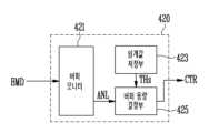
도 4는 도 3에 도시된 버퍼 관리부(420)의 예시적인 실시 예를 나타내는 블록도이다. 도 4를 참조하면, 버퍼 관리부(420)는 버퍼 모니터(421), 임계값 저장부(423) 및 버퍼 용량 결정부(425)를 포함한다. 버퍼 관리부(421)는 버퍼 메모리(410)의 사용 상태를 나타내는 버퍼 확인 데이터(BMD)를 수신하고, 이에 기초하여 버퍼 분석 데이터(ANL)를 출력한다. 임계값 저장부(423)는 입력 버퍼부(411) 및 출력 버퍼부(413)의 용량을 변경하기 위한 임계값들(THs)을 저장한다. 임계값들(THs)은 용량 변경의 여부를 결정하기 위해 버퍼 분석 데이터(ANL)와 비교되는 기준값일 수 있다. 버퍼 용량 결정부(425)는 버퍼 분석 데이터(ANL)와 임계값들(THs)을 비교하여, 입력 버퍼부(411) 또는 출력 버퍼부(413)의 용량을 변경할 것을 결정하고, 이에 따른 제어 신호(CTR)를 생성한다. 제어 신호(CTR)는 버퍼 메모리(410)로 전달된다. 보다 구체적으로, 제어 신호(CTR)는 입력 버퍼부(411)와 출력 버퍼부(413)를 구분하는 버퍼 포인터가 가리키는 위치를 변경하기 위한 신호일 수 있다. 상기 버퍼 포인터가 가리키는 위치가 변경됨에 따라 입력 버퍼부(411)와 출력 버퍼부(413)의 용량이 변경된다. 버퍼 포인터가 가리키는 위치의 변경에 따라 입력 버퍼부(411)와 출력 버퍼부(413)의 용량이 변경되는 것에 대하여는 도 5를 참조하여 더욱 자세히 후술하기로 한다.FIG. 4 is a block diagram illustrating an exemplary embodiment of the
도 3 및 도 4에서, 버퍼 관리부(420)는 제어부(430)와는 별개로 구비되는 구성요소인 것으로 도시되었다. 그러나, 본 발명의 실시 예에 따른 메모리 컨트롤러(1200)는 이에 한정되지 않으며, 버퍼 관리부(420)와 제어부(430)가 일체로 구성될 수도 있다. 이 경우, 버퍼 관리부(420)와 제어부(430)는 하나의 마이크로 프로세서로서 구성될 수 있다.In FIGS. 3 and 4 , the
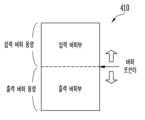
도 5는 도 3의 버퍼 메모리(410)를 모식적으로 나타내는 블록도이다.FIG. 5 is a schematic block diagram of the
도 5를 참조하면, 버퍼 메모리(410)는 입력 버퍼부(411)와 출력 버퍼부(413)를 포함한다. 입력 버퍼부(411)와 출력 버퍼부(413)는 서로 별개로 구성되지 않고, 버퍼 메모리(410) 내에서 논리적으로 구분되는 메모리 영역으로서 구성될 수 있다. 이 경우, 입력 버퍼부(411)와 출력 버퍼부(413)를 구분하기 위해, 버퍼 메모리(410)의 특정 주소를 가리키는 버퍼 포인터가 사용될 수 있다. 버퍼 포인터는 입력 버퍼부(411)와 출력 버퍼부(413)의 논리적인 경계를 가리키는 메모리 포인터일 수 있다.Referring to FIG. 5 , the
버퍼 포인터가 가리키는 위치를 변경함에 따라 입력 버퍼부(411)와 출력 버퍼부(413)의 용량을 변경할 수 있다. 도 5에 도시된 버퍼 포인터가 가리키는 위치를 상단으로 이동하는 경우, 입력 버퍼부(411)의 용량인 입력 버퍼 용량이 감소하고, 출력 버퍼부(413)의 용량인 출력 버퍼 용량이 증가할 것이다. 반대로, 버퍼 포인터가 가리키는 위치를 하단으로 이동하는 경우, 입력 버퍼부(411)의 용량인 입력 버퍼 용량이 증가하고, 출력 버퍼부(413)의 용량인 출력 버퍼 용량이 감소할 것이다.The capacities of the
본 발명의 일 실시 예에 따른 메모리 컨트롤러(1200)에 의하면, 입력 버퍼부(411) 및 출력 버퍼부(413)의 사용 상태에 따라 상기 버퍼 포인터가 가리키는 위치를 변경한다. 이에 따라 입력 버퍼부(411) 및 출력 버퍼부(413)의 용량을 동적으로 변경할 수 있다. 결과적으로, 사용자의 특성에 따라 입력 버퍼부(411) 및 출력 버퍼부(413)의 용량을 적응적으로 변경하여, 메인 메모리(400)와 데이터 변환부(440) 사이의 쓰루풋을 증가시킬 수 있다. 따라서, 메모리 시스템(1000)의 동작 속도가 향상된다. According to the
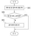
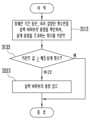
도 6은 본 발명의 다른 실시 예에 따른 메모리 컨트롤러의 동작 방법을 나타내는 순서도이다. 도 6을 참조하면, 본 발명의 다른 실시 예에 따른 메모리 컨트롤러의 동작 방법은, 버퍼 메모리(410)의 입력 버퍼부(411)와 출력 버퍼부(413)의 사용 상태를 확인하는 단계(S110) 및 사용 상태에 기초하여, 입력 버퍼부(411)와 출력 버퍼부(413)의 용량을 조절하는 단계(S200)를 포함한다.6 is a flowchart illustrating a method of operating a memory controller according to another exemplary embodiment of the present disclosure. Referring to FIG. 6 , a method of operating a memory controller according to another embodiment of the present invention includes checking the use states of the
단계(S100) 및 단계(S200)의 예시적인 실시 예들에 대해서는 도 8a 내지 도 14를 참조하여 자세히 후술하기로 한다.Exemplary embodiments of steps S100 and S200 will be described later in detail with reference to FIGS. 8A to 14 .
도 7은 입력 버퍼부(411)의 임계 용량을 설명하기 위한 도면이다.7 is a diagram for explaining the critical capacity of the
도 7을 참조하면, 설명의 편의를 위해 버퍼 메모리(410)의 입력 버퍼부(411)만이 도시되어 있고, 출력 버퍼부(413)의 도시는 생략되었다. 그러나, 버퍼 메모리(410)는 출력 버퍼부(413) 또한 포함하며, 출력 버퍼부(413)는 도 7의 입력 버퍼부(411)와 유사하게 도시될 수 있음을 알 수 있을 것이다.Referring to FIG. 7 , for convenience of description, only the
도 7을 참조하면, 전체 입력 버퍼부(411)의 용량 중에, 사용 중인 입력 버퍼 용량이 해칭(hatching) 표시되었다. 또한, 도 7에는 임계 용량 또한 표시되었다. 임계 용량은 입력 버퍼부(411)의 용량 변경을 위해 비교하기 위한 기준 값으로 이용될 수 있다.Referring to FIG. 7 , among the capacities of the entire
사용자의 특성에 따라, 메모리 시스템(1000)이 데이터의 라이트 동작을 빈번하게 수행하는 경우 입력 버퍼부(411)의 사용중인 입력 버퍼 용량이 증가하는 경향성이 높을 것이다. 이에 따라, 사용 중인 입력 버퍼 용량이 임계 용량보다 큰 값을 갖는 상황이 빈번하게 발생할 것이다. 만약 사용 중인 입력 버퍼 용량이 입력 버퍼부(411)의 전체 용량과 동일해지는 경우, 더 이상 입력 데이터가 입력 버퍼부(411)에 저장될 수 없다. 이 경우 입력 데이터가 입력 버퍼부(411)에 저장되는 것이 지연되므로, 메인 메모리(400)로부터 데이터 변환부(440)로의 데이터 병목 현상이 발생한다.Depending on the user's characteristics, when the
따라서, 사용 중인 입력 버퍼 용량이 현재 임계 용량보다 큰 경우, 또는 사용 중인 입력 버퍼 용량이 임계 용량을 초과하는 상황이 빈번히 발생하는 경우, 입력 버퍼부(411)의 용량을 증가시켜 데이터 병목 현상을 예방할 수 있다. 이에 따라, 메인 메모리(400)로부터 데이터 변환부(440)로의 쓰루풋이 증가한다.Therefore, when the capacity of the input buffer in use is greater than the current critical capacity, or when a situation in which the capacity of the input buffer in use exceeds the critical capacity frequently occurs, it is possible to prevent a data bottleneck by increasing the capacity of the
반대로, 사용자의 특성에 따라, 메모리 시스템(1000)이 데이터의 리드 동작을 빈번하게 수행하는 경우 출력 버퍼부(413)의 사용중인 출력 버퍼 용량이 증가하는 경향성이 높을 것이다. 이에 따라, 사용 중인 출력 버퍼 용량이 임계 용량보다 큰 값을 갖는 상황이 빈번하게 발생할 것이다. 만약 사용 중인 출력 버퍼 용량이 출력 버퍼부(413)의 전체 용량과 동일해지는 경우, 더 이상 출력 데이터가 입력 버퍼부(411)에 저장될 수 없다. 이 경우 입력 데이터가 입력 버퍼부(411)에 저장되는 것이 지연되므로, 데이터 변환부(440)로부터 메인 메모리(400)로의 데이터 병목 현상이 발생한다.Conversely, if the
따라서, 사용 중인 출력 버퍼 용량이 현재 임계 용량보다 큰 경우, 또는 사용 중인 출력 버퍼 용량이 임계 용량을 초과하는 상황이 빈번히 발생하는 경우, 출력 버퍼부(413)의 용량을 증가시켜 데이터 병목 현상을 예방할 수 있다. 이에 따라, 데이터 변환부(440)로부터 메인 메모리(400)로의 쓰루풋이 증가한다.Therefore, if the capacity of the output buffer in use is greater than the current critical capacity, or if a situation in which the capacity of the output buffer in use exceeds the critical capacity frequently occurs, the capacity of the
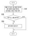
도 8a는 본 발명에 따른 메모리 컨트롤러의 동작 방법의 일 예를 나타내는 순서도이다. 도 8b는 본 발명에 따른 메모리 컨트롤러의 동작 방법의 다른 예를 나타내는 순서도이다. 도 8a는 입력 버퍼부(411)의 사용 상태를 확인하여 입력 버퍼부(411)의 용량을 증가시키는 실시 예를 도시하고 있고, 도 8b는 출력 버퍼부(413)의 사용 상태를 확인하여 출력 버퍼부(413)의 용량을 증가시키는 실시 예를 도시하고 있다. 이하에서는 도 4를 함께 참조하여, 본 발명의 예시적인 실시 예에 따른 메모리 컨트롤러의 동작 방법을 설명하기로 한다.8A is a flowchart illustrating an example of a method of operating a memory controller according to the present invention. 8B is a flowchart illustrating another example of a method of operating a memory controller according to the present invention. 8A shows an embodiment in which the capacity of the
도 8a를 참조하면, 본 발명의 예시적인 실시 예에 따른 메모리 컨트롤러의 동작 방법은 현재 사용 중인 입력 버퍼부(411)의 용량을 확인하는 단계(S110), 사용 중인 입력 버퍼 용량이 임계 용량보다 크거나 같은지 판별하는 단계(S130)를 포함한다. 단계들(S110, S130)은 도 6의 단계(S100)에 포함되는 단계들일 수 있다.Referring to FIG. 8A , a method of operating a memory controller according to an exemplary embodiment of the present invention includes checking the capacity of the
한편, 본 발명의 예시적인 실시 예에 따른 메모리 컨트롤러의 동작 방법은, 단계(S130)의 수행 결과 사용 중인 입력 버퍼 용량이 임계 용량보다 크거나 같은 경우 입력 버퍼부(411)의 용량을 증가시키는 단계(S210)를 더 포함한다. 단계(S210)는 도 6의 단계(S200)에 포함되는 단계일 수 있다.Meanwhile, a method of operating a memory controller according to an exemplary embodiment of the present disclosure includes increasing the capacity of the
단계(S110)에서, 현재 사용 중인 입력 버퍼 용량이 도 4에 도시된 버퍼 확인 데이터(BMD)의 형태로 버퍼 모니터(421)에 전달된다. 버퍼 모니터(421)는 버퍼 확인 데이터(BMD)에 포함된, 입력 버퍼부(411)의 현재 사용 용량을 버퍼 분석 데이터(ANL)로서 버퍼 용량 결정부(425)에 전달한다.In step S110, the currently used input buffer capacity is transmitted to the
단계(S130)에서, 버퍼 용량 결정부(425)는 입력 버퍼부(411)의 현재 사용 중인 용량을 임계 용량과 비교한다. 임계값 저장부(423)는 임계값(THs)으로서 상기 임계 용량을 버퍼 용량 결정부(425)로 전달한다. 입력 버퍼부(411)의 현재 사용 중인 용량이 임계 용량보다 크거나 같은 경우, 버퍼 용량 결정부(425)는 입력 버퍼부(411)의 용량을 증가시키기 위한 제어 신호(CTR)를 생성하여 버퍼 메모리(410)로 전달한다. 제어 신호(CTR)에 따라 버퍼 포인터가 가리키는 위치가 변경되어 입력 버퍼부(411)의 용량이 증가한다.In step S130, the buffer
입력 버퍼부(411)의 현재 사용 중인 용량이 임계 용량보다 작은 경우, 입력 버퍼부(411)의 용량은 변경되지 않을 것이다. 도 8a에 도시된 각 단계들(S110, S130, S210)은 일정 시간 간격마다 주기적으로 수행될 수 있다. 즉, 버퍼 관리부(420)는 주기적으로 버퍼 확인 데이터(BMD)를 수신하고, 이에 기초하여 입력 버퍼부(411)의 용량을 변경할지 여부를 결정할 수 있다.If the currently used capacity of the
도 8b를 참조하면, 본 발명의 예시적인 실시 예에 따른 메모리 컨트롤러의 동작 방법은 현재 사용 중인 출력 버퍼부(413)의 용량을 확인하는 단계(S115), 사용 중인 출력 버퍼 용량이 임계 용량보다 크거나 같은지 판별하는 단계(S135)를 포함한다. 단계들(S115, S135)은 도 6의 단계(S100)에 포함되는 단계들일 수 있다.Referring to FIG. 8B , a method of operating a memory controller according to an exemplary embodiment of the present invention includes checking the capacity of the
한편, 본 발명의 예시적인 실시 예에 따른 메모리 컨트롤러의 동작 방법은, 단계(S135)의 수행 결과 사용 중인 출력 버퍼 용량이 임계 용량보다 크거나 같은 경우 출력 버퍼부(413)의 용량을 증가시키는 단계(S215)를 더 포함한다. 단계(S215)는 도 6의 단계(S200)에 포함되는 단계일 수 있다.Meanwhile, a method of operating a memory controller according to an exemplary embodiment of the present disclosure includes increasing the capacity of the
단계들(S115, S135, S215)를 수행함에 따라, 도 8a와 유사하게 출력 버퍼부(413)의 용량이 변경됨을 알 수 있을 것이다. 이에 중복되는 설명은 생략하기로 한다.As steps S115, S135, and S215 are performed, it will be appreciated that the capacity of the
도 9는 입력 버퍼부(411)와 출력 버퍼부(413)의 임계 용량들을 설명하기 위한 블록도이다.9 is a block diagram for explaining critical capacities of the
도 9를 참조하면, 버퍼 메모리(410) 내 입력 버퍼부(411) 및 출력 버퍼부(413)가 모식적으로 도시되어 있다. 입력 버퍼부(411) 및 출력 버퍼부(413)는 버퍼 포인터에 의해 구분되고, 버퍼 포인터가 가리키는 위치가 변경됨에 따라 입력 버퍼부(411) 및 출력 버퍼부(413)의 용량이 변경될 것이다. 한편, 입력 버퍼부(411)에 대하여는 제1 임계 용량이 미리 결정되어 있고, 출력 버퍼부(413)에 대해서는 제2 임계 용량이 미리 결정되어 있다. 제1 임계 용량 및 제2 임계 용량은 도 4에 도시된 임계값들(THs)로서 임계값 저장부(423)에 저장될 수 있다. 한편, 제1 임계 용량 및 제2 임계 용량이 동일한 값을 가질 수도 있으나, 필요에 따라 제1 임계 용량 및 제2 임계 용량은 서로 상이한 값을 가질 수도 있다.Referring to FIG. 9 , an
도 9에서, 사용 중인 입력 버퍼 용량이 제1 임계 용량보다 작고, 사용 중인 출력 버퍼 용량이 제2 임계 용량보다 작다. 이 상태에서 사용 중인 입력 버퍼 용량이 제1 임계 용량을 초과하는 경우, 도 8a를 통해 설명한 바와 같이 입력 버퍼부(411)의 용량을 증가시킬 수 있다. 출력 버퍼부(411)에 아직 여유 공간이 있기 때문이다.In FIG. 9 , the capacity of the input buffer in use is less than the first threshold capacity, and the capacity of the output buffer in use is less than the second threshold capacity. In this state, when the capacity of the input buffer in use exceeds the first threshold capacity, the capacity of the
그러나, 도 9와는 달리 사용 중인 출력 버퍼 용량이 제2 임계 용량을 초과하는 상황에서 사용 중인 입력 버퍼 용량이 제1 임계 용량을 초과하는 경우, 입력 버퍼부(411)의 용량을 증가시키는 경우 출력 버퍼부(413)의 용량이 부족할 수 있다. 따라서 이 경우에는 입력 버퍼부(411)의 용량을 증가시키지 않는 것이 바람직할 것이다. 이하 도 10을 참조하여 위와 같은 필요성을 반영한 메모리 컨트롤러의 동작 방법을 설명하기로 한다.However, unlike FIG. 9, when the capacity of the input buffer in use exceeds the first threshold capacity in a situation where the capacity of the output buffer in use exceeds the second threshold capacity, the capacity of the
도 10은 본 발명의 또다른 실시 예에 따른 메모리 컨트롤러의 동작 방법을 나타내는 순서도이다.10 is a flowchart illustrating a method of operating a memory controller according to another embodiment of the present invention.
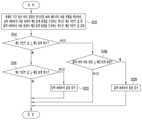
도 10을 참조하면, 먼저 현재 사용 중인 입력 버퍼부의 용량을 확인하고(S120), 사용 중인 입력 버퍼 용량이 제1 임계 용량보다 크거나 같은지 판별한다(S140).Referring to FIG. 10 , first, the capacity of the input buffer unit currently in use is checked (S120), and it is determined whether the capacity of the input buffer in use is greater than or equal to the first threshold capacity (S140).
사용 중인 입력 버퍼 용량이 제1 임계 용량보다 크거나 같은 경우, 현재 사용 중인 출력 버퍼부의 용량을 확인하고(S160), 사용 중인 출력 버퍼 용량이 제2 임계 용량보다 크거나 같은지 판별한다(S180).When the input buffer capacity in use is greater than or equal to the first threshold capacity, the capacity of the output buffer unit currently in use is checked (S160), and it is determined whether the output buffer capacity in use is greater than or equal to the second threshold capacity (S180).
사용 중인 출력 버퍼 용량이 제2 임계 용량보다 크거나 같은 경우, 출력 버퍼부(413)의 용량에 여유가 없는 상황이므로, 입력 버퍼부(411)의 용량을 증가 시키지 않고 프로세스를 종료한다. 사용 중인 출력 버퍼 용량이 제2 임계 용량보다 작은 경우, 출력 버퍼부(413)의 용량에 여유가 있는 상황이므로, 입력 버퍼부(411)의 용량을 증가 시킨다(S220).If the capacity of the output buffer in use is greater than or equal to the second threshold capacity, the capacity of the
한편, 단계(S140)의 수행 결과 사용 중인 입력 버퍼 용량이 제1 임계 용량보다 작은 경우, 이는 입력 버퍼부(411)의 용량에 여유가 있음을 의미한다. 이어 현재 사용 중인 출력 버퍼부의 용량을 확인하고(S165), 사용 중인 출력 버퍼 용량이 제2 임계 용량보다 크거나 같은지 판별한다(S185).Meanwhile, when the capacity of the input buffer in use as a result of performing step S140 is less than the first threshold capacity, this means that the capacity of the
입력 버퍼부(411)의 용량에 여유가 있는 상황에서, 사용 중인 출력 버퍼 용량이 제2 임계 용량보다 크거나 같은 경우, 출력 버퍼부(413)의 용량을 증가 시킨다(S225). 사용 중인 출력 버퍼 용량이 제2 임계 용량보다 작은 경우에는 출력 버퍼부(413)의 용량을 증가 시키지 않고 프로세스를 종료한다.When the capacity of the
도 10에서, 단계들(S120, S140, S160, S165, S180, S185)은 도 6의 단계(S100)에 포함되고, 단계들(S220, S225)은 도 6의 단계(S200)에 포함됨을 알 수 있을 것이다.In FIG. 10, it can be seen that steps S120, S140, S160, S165, S180, and S185 are included in step S100 of FIG. 6, and steps S220 and S225 are included in step S200 of FIG. You will be able to.
도 10에 도시된 실시 예에 따르면, 입력 버퍼부(411)의 현재 사용중인 용량이 제1 임계값을 초과하는 경우더라도, 출력 버퍼부(413)의 여유 용량에 따라 입력 버퍼부(411)의 용량 증가 여부를 결정한다. 한편, 입력 버퍼부(411)의 현재 용량에 여유가 있는 경우, 출력 버퍼부(413)의 현재 사용 중인 용량이 제2 임계값을 초과할 때 출력 버퍼부(413)의 용량을 증가시킨다. 이에 따라, 입력 버퍼부(411) 및 출력 버퍼부(413) 양쪽의 사용 상태를 모두 고려하여, 입력 버퍼부(411)와 출력 버퍼부(413)의 용량을 변경할 수 있다.According to the embodiment shown in FIG. 10 , even if the currently used capacity of the
도 11a는 본 발명에 따른 메모리 컨트롤러의 동작 방법의 일 예를 나타내는 순서도이다. 도 11b는 본 발명에 따른 메모리 컨트롤러의 동작 방법의 다른 예를 나타내는 순서도이다. 도 11a는 입력 버퍼부(411)의 사용 상태를 확인하여 입력 버퍼부(411)의 용량을 증가시키는 실시 예를 도시하고 있고, 도 11b는 출력 버퍼부(413)의 사용 상태를 확인하여 출력 버퍼부(413)의 용량을 증가시키는 실시 예를 도시하고 있다. 이하에서는 도 4를 함께 참조하여, 본 발명의 예시적인 실시 예에 따른 메모리 컨트롤러의 동작 방법을 설명하기로 한다.11A is a flowchart illustrating an example of a method of operating a memory controller according to the present invention. 11B is a flowchart illustrating another example of a method of operating a memory controller according to the present invention. 11A shows an embodiment in which the capacity of the
도 11a를 참조하면, 본 발명의 예시적인 실시 예에 따른 메모리 컨트롤러의 동작 방법은 정해진 기간 동안, 미리 결정된 횟수만큼 입력 버퍼의 용량을 확인하여, 임계 용량을 초과하는 횟수를 카운트하는 단계(S111), 카운트 값이 미리 결정된 제1 임계 횟수보다 크거나 같은지 판별하는 단계(S131)를 포함한다. 단계들(S111, S131)은 도 6의 단계(S100)에 포함되는 단계들일 수 있다.Referring to FIG. 11A , a method of operating a memory controller according to an exemplary embodiment of the present disclosure includes checking the capacity of an input buffer a predetermined number of times during a predetermined period of time and counting the number of times exceeding a threshold capacity (S111). , determining whether the count value is greater than or equal to a first predetermined threshold number of times (S131). Steps S111 and S131 may be steps included in step S100 of FIG. 6 .
도 8a의 단계(S110)에서는 현재 시점에서 사용 중인 입력 버퍼 용량을 확인하는 반면, 도11a의 단계(S111)에서는 일정 기간 동안 입력 버퍼의 용량을 여러 번 확인하여, 확인된 사용 용량이 임계 용량을 초과하는 횟수가 몇번인지를 카운트한다. 상기 카운트 값이 큰 경우, 이는 도 7에서 사용 중인 입력 버퍼 용량이 임계 용량을 빈번하게 초과함을 의미한다. 상기 카운트 값이 작은 경우, 이는 사용 중인 입력 버퍼 용량이 임계 용량을 빈번하지 않게 초과함을 의미한다.In step S110 of FIG. 8A, the capacity of the input buffer currently in use is checked, whereas in step S111 of FIG. 11A, the capacity of the input buffer is checked several times over a period of time so that the checked used capacity exceeds the critical capacity. Count how many times it is exceeded. When the count value is large, it means that the capacity of the input buffer in use in FIG. 7 frequently exceeds the threshold capacity. If the count value is small, it means that the input buffer capacity in use infrequently exceeds the threshold capacity.
이에 따라, 단계(S131)에서 카운트 값이 미리 결정된 제1 임계 횟수보다 크거나 같은 경우, 이는 사용 중인 입력 버퍼 용량이 임계 용량을 빈번하게 초과하는 경우이므로 입력 버퍼의 용량을 증가시킨다(S211). 단계(S211)는 도 6의 단계(S200)에 포함되는 단계일 수 있다.Accordingly, in step S131, if the count value is greater than or equal to the first predetermined threshold number of times, this is a case where the input buffer capacity in use frequently exceeds the threshold capacity, so the capacity of the input buffer is increased (S211). Step S211 may be a step included in step S200 of FIG. 6 .
한편, 단계(S131)에서 카운트 값이 미리 결정된 제1 임계 횟수보다 작은 경우, 이는 사용 중인 입력 버퍼 용량이 임계 용량을 빈번하게 초과하지 않는 경우이므로 입력 버퍼의 용량을 증가시키지 않고 프로세스를 종료한다.On the other hand, in step S131, if the count value is less than the first predetermined threshold number of times, this is a case where the capacity of the input buffer in use does not frequently exceed the threshold capacity, so the process ends without increasing the capacity of the input buffer.
단계(S111)에서, 현재 사용 중인 입력 버퍼 용량이 도 4에 도시된 버퍼 확인 데이터(BMD)의 형태로 버퍼 모니터(421)에 전달된다. 버퍼 모니터(421)는 버퍼 확인 데이터(BMD)를 일정 기간 동안 누적 분석하여, 사용 중인 입력 버퍼 용량이 임계 용량을 몇 번 초과하는지 카운트한다. 카운트 값은 버퍼 분석 데이터(ANL)로서 버퍼 용량 결정부(425)에 전달된다.In step S111, the currently used input buffer capacity is transmitted to the
단계(S131)에서, 버퍼 용량 결정부(425)는 버퍼 분석 데이터(ANL)로서 전달된 카운트 값을 임계 횟수와 비교한다. 임계값 저장부(423)는 임계값(THs)으로서 상기 임계 횟수를 버퍼 용량 결정부(425)로 전달한다. 카운트 값이 임계 횟수보다 크거나 같은 경우, 버퍼 용량 결정부(425)는 입력 버퍼부(411)의 용량을 증가시키기 위한 제어 신호(CTR)를 생성하여 버퍼 메모리(410)로 전달한다. 제어 신호(CTR)에 따라 버퍼 포인터가 가리키는 위치가 변경되어 입력 버퍼부(411)의 용량이 증가한다.In step S131, the buffer
카운트 값이 임계 횟수보다 작은 경우, 입력 버퍼부(411)의 용량은 변경되지 않을 것이다.When the count value is smaller than the threshold number of times, the capacity of the
도 11b를 참조하면, 본 발명의 예시적인 실시 예에 따른 메모리 컨트롤러의 동작 방법은 정해진 기간 동안, 미리 결정된 횟수만큼 출력 버퍼의 용량을 확인하여, 임계 용량을 초과하는 횟수를 카운트하는 단계(S116), 카운트 값이 미리 결정된 제2 임계 횟수보다 크거나 같은지 판별하는 단계(S136)를 포함한다. 단계들(S116, S136)은 도 6의 단계(S100)에 포함되는 단계들일 수 있다.Referring to FIG. 11B , a method of operating a memory controller according to an exemplary embodiment of the present disclosure includes checking the capacity of an output buffer a predetermined number of times during a predetermined period of time and counting the number of times exceeding a threshold capacity ( S116 ). , determining whether the count value is greater than or equal to a predetermined second threshold number (S136). Steps S116 and S136 may be steps included in step S100 of FIG. 6 .
한편, 본 발명의 예시적인 실시 예에 따른 메모리 컨트롤러의 동작 방법은, 단계(S136)의 수행 결과 카운트 값이 제2 임계 횟수보다 크거나 같은 경우 출력 버퍼부(413)의 용량을 증가시키는 단계(S216)를 더 포함한다. 단계(S216)는 도 6의 단계(S200)에 포함되는 단계일 수 있다.On the other hand, in the operating method of the memory controller according to an exemplary embodiment of the present invention, when the count value is greater than or equal to the second threshold number of times as a result of performing step S136, increasing the capacity of the output buffer unit 413 ( S216) is further included. Step S216 may be a step included in step S200 of FIG. 6 .
단계들(S116, S136, S216)를 수행함에 따라, 도 11a와 유사하게 출력 버퍼부(413)의 용량이 변경됨을 알 수 있을 것이다. 이에 중복되는 설명은 생략하기로 한다.As steps S116, S136, and S216 are performed, it will be appreciated that the capacity of the
도 12는 본 발명의 또다른 실시 예에 따른 메모리 컨트롤러의 동작 방법을 나타내는 순서도이다.12 is a flowchart illustrating a method of operating a memory controller according to another embodiment of the present invention.
도 12를 참조하면, 정해진 기간 동안 미리 결정된 횟수만큼 버퍼 메모리의 사용 현황을 확인하여, 입력 버퍼부의 사용 용량이 제1 임계 용량을 초과하는 횟수인 제1 카운트 값 및 출력 버퍼부의 사용 용량이 제2 임계 용량을 초과하는 횟수인 제2 카운트 값을 결정하고(S121), 먼저 제1 카운트 값이 제1 임계 횟수보다 크거나 같은지 판별한다(S141).Referring to FIG. 12, the usage status of the buffer memory is checked a predetermined number of times during a predetermined period, and a first count value, which is the number of times the used capacity of the input buffer unit exceeds the first threshold capacity, and the used capacity of the output buffer unit is a second A second count value, which is the number of times exceeding the threshold capacity, is determined (S121), and first, it is determined whether the first count value is greater than or equal to the first threshold number (S141).
제1 카운트 값이 제1 임계 횟수보다 크거나 같은 경우, 제2 카운트 값이 제2 임계 횟수보다 크거나 같은지 판별한다(S181). 제2 카운트 값이 제2 임계 횟수보다 크거나 같은 경우, 출력 버퍼부(413)의 사용 용량 또한 빈번하게 제2 임계 용량을 초과함을 의마한다. 이에 따라, 입력 버퍼부(411)의 용량을 증가 시키지 않고 프로세스를 종료한다. 제2 카운트 값이 제2 임계 횟수보다 작은 경우, 출력 버퍼부(413)의 사용 용량이 제2 임계 용량을 빈번하게 초과하지 않음을 의미한다. 이에 따라, 출력 버퍼부(413)의 용량에 여유가 있을 것으로 예상되므로, 입력 버퍼부(411)의 용량을 증가 시킨다(S221).When the first count value is greater than or equal to the first threshold number of times, it is determined whether the second count value is greater than or equal to the second threshold number of times (S181). When the second count value is greater than or equal to the second threshold number, it means that the used capacity of the
한편, 단계(S141)의 수행 결과 제1 카운트 값이 제1 임계 횟수보다 작은 경우, 이는 입력 버퍼부(411)의 사용 용량이 제1 임계 용량을 빈번하게 초과하지 않음을 의마한다. 이어 제2 카운트 값이 제2 임계 횟수보다 크거나 같은지 판별한다(S186).Meanwhile, when the first count value is smaller than the first threshold number of times as a result of performing step S141, this means that the used capacity of the
입력 버퍼부(411)가 제1 임계 용량을 빈번하게 초과하지 않는 상황에서, 제2 카운트 값이 제2 임계 횟수보다 크거나 같은 경우, 출력 버퍼부(413)의 용량을 증가 시킨다(S226). 제2 카운트 값이 제2 임계 횟수보다 작은 경우에는 출력 버퍼부(413)의 용량을 증가 시키지 않고 프로세스를 종료한다.In a situation where the
도 12에서, 단계들(S121, S141, S181, S186)은 도 6의 단계(S100)에 포함되고, 단계들(S221, S226)은 도 6의 단계(S200)에 포함됨을 알 수 있을 것이다.In FIG. 12 , it will be appreciated that steps S121 , S141 , S181 , and S186 are included in step S100 of FIG. 6 , and steps S221 and S226 are included in step S200 of FIG. 6 .
도 12에 도시된 실시 예에 따르면, 입력 버퍼부(411)의 사용중인 용량이 제1 임계값을 빈번히 초과하는 경우더라도, 출력 버퍼부(413)의 상황에 따라 입력 버퍼부(411)의 용량 증가 여부를 결정한다. 한편, 입력 버퍼부(411)의 사용 중인 용량이 제1 임계값을 빈번하게 초과하지 않는 경우에는, 출력 버퍼부(413)의 사용 중인 용량이 제2 임계값을 빈번하게 초과할 때 출력 버퍼부(413)의 용량을 증가시킨다. 이에 따라, 입력 버퍼부(411) 및 출력 버퍼부(413) 양쪽의 사용 상태를 모두 고려하여, 입력 버퍼부(411)와 출력 버퍼부(413)의 용량을 변경할 수 있다.According to the embodiment shown in FIG. 12 , even when the capacity in use of the
도 13a는 본 발명에 따른 메모리 컨트롤러의 동작 방법의 일 예를 나타내는 순서도이다. 도 13b는 본 발명에 따른 메모리 컨트롤러의 동작 방법의 다른 예를 나타내는 순서도이다. 도 13a는 입력 버퍼부(411)의 사용 상태를 확인하여 입력 버퍼부(411)의 용량을 감소시키는 실시 예를 도시하고 있고, 도 13b는 출력 버퍼부(413)의 사용 상태를 확인하여 출력 버퍼부(413)의 용량을 감소시키는 실시 예를 도시하고 있다.13A is a flowchart illustrating an example of a method of operating a memory controller according to the present invention. 13B is a flowchart illustrating another example of a method of operating a memory controller according to the present invention. 13A illustrates an embodiment in which the capacity of the
도 13a를 참조하면, 본 발명의 예시적인 실시 예에 따른 메모리 컨트롤러의 동작 방법은 정해진 기간 동안, 미리 결정된 횟수만큼 입력 버퍼의 용량을 확인하여, 임계 용량을 초과하는 횟수를 카운트하는 단계(S113), 카운트 값이 미리 결정된 제3 임계 횟수보다 작은지 판별하는 단계(S133)를 포함한다. 단계들(S113, S133)은 도 6의 단계(S100)에 포함되는 단계들일 수 있다.Referring to FIG. 13A , a method of operating a memory controller according to an exemplary embodiment of the present disclosure includes checking the capacity of an input buffer a predetermined number of times during a predetermined period of time and counting the number of times exceeding a threshold capacity (S113). , determining whether the count value is less than a predetermined third threshold number of times (S133). Steps S113 and S133 may be steps included in step S100 of FIG. 6 .
도13a의 단계(S113)에서는 일정 기간 동안 입력 버퍼의 용량을 여러 번 확인하여, 확인된 사용 용량이 임계 용량을 초과하는 횟수가 몇번인지를 카운트한다. 상기 카운트 값이 작은 경우, 이는 도 7에서 사용 중인 입력 버퍼 용량이 임계 용량을 초과하는 빈도가 낮음을 의미한다.In step S113 of FIG. 13A, the capacity of the input buffer is checked several times during a certain period of time, and the number of times the used capacity exceeds the threshold capacity is counted. When the count value is small, it means that the frequency in which the capacity of the input buffer in use exceeds the threshold capacity in FIG. 7 is low.
이에 따라, 단계(S133)에서 카운트 값이 미리 결정된 제3 임계 횟수보다 작은 경우, 이는 사용 중인 입력 버퍼 용량이 임계 용량을 초과하는 빈도수가 낮은 경우이므로 입력 버퍼의 용량을 감소시킨다(S213). 단계(S213)는 도 6의 단계(S200)에 포함되는 단계일 수 있다.Accordingly, in step S133, if the count value is less than the predetermined third threshold number of times, this is a case where the frequency of exceeding the threshold capacity of the input buffer capacity in use is low, and thus the capacity of the input buffer is reduced (S213). Step S213 may be a step included in step S200 of FIG. 6 .
한편, 단계(S133)에서 카운트 값이 미리 결정된 제3 임계 횟수보다 크거나 같은 경우, 이는 사용 중인 입력 버퍼 용량이 임계 용량을 어느 정도 빈번하게 초과하는 경우이므로 입력 버퍼의 용량을 감소시키지 않고 프로세스를 종료한다.On the other hand, if the count value in step S133 is greater than or equal to the third predetermined threshold number of times, this is a case where the capacity of the input buffer in use exceeds the threshold capacity to some extent frequently, so the process is performed without reducing the capacity of the input buffer. quit
단계(S113)에서, 현재 사용 중인 입력 버퍼 용량이 도 4에 도시된 버퍼 확인 데이터(BMD)의 형태로 버퍼 모니터(421)에 전달된다. 버퍼 모니터(421)는 버퍼 확인 데이터(BMD)를 일정 기간 동안 누적 분석하여, 사용 중인 입력 버퍼 용량이 임계 용량을 몇 번 초과하는지 카운트한다. 카운트 값은 버퍼 분석 데이터(ANL)로서 버퍼 용량 결정부(425)에 전달된다.In step S113, the currently used input buffer capacity is transferred to the
단계(S133)에서, 버퍼 용량 결정부(425)는 버퍼 분석 데이터(ANL)로서 전달된 카운트 값을 제3 임계 횟수와 비교한다. 임계값 저장부(423)는 임계값(THs)으로서 상기 제3 임계 횟수를 버퍼 용량 결정부(425)로 전달한다. 카운트 값이 제3 임계 횟수보다 작은 경우, 버퍼 용량 결정부(425)는 입력 버퍼부(411)의 용량을 감소시키기 위한 제어 신호(CTR)를 생성하여 버퍼 메모리(410)로 전달한다. 제어 신호(CTR)에 따라 버퍼 포인터가 가리키는 위치가 변경되어 입력 버퍼부(411)의 용량이 감소한다.In step S133, the buffer
제3 임계 횟수의 값은 필요에 따라 다양하게 결정할 수 있다. 예시적으로, 상기 제3 임계 횟수가 1의 값을 갖는 경우, 단계(S133)에서는 카운트 값이 1보다 작은지 여부를 판단한다. 즉, 단계(S133)에서, 카운트 값이 0인 경우, 미리 정해진 기간 동안 사용중인 입력 버퍼 용량이 임계 용량을 초과한 적이 없음을 나타낸다. 따라서 이 경우 입력 버퍼부의 용량을 감소시킨다(S210).The value of the third threshold number of times may be variously determined as needed. Exemplarily, when the third threshold number has a value of 1, in step S133, it is determined whether the count value is less than 1. That is, in step S133, if the count value is 0, it indicates that the input buffer capacity in use has never exceeded the threshold capacity for a predetermined period of time. Therefore, in this case, the capacity of the input buffer unit is reduced (S210).
카운트 값이 제3 임계 횟수보다 크거나 같은 경우, 입력 버퍼부(411)의 용량은 변경되지 않을 것이다.When the count value is greater than or equal to the third threshold number of times, the capacity of the
도 13b를 참조하면, 본 발명의 예시적인 실시 예에 따른 메모리 컨트롤러의 동작 방법은 정해진 기간 동안, 미리 결정된 횟수만큼 출력 버퍼의 용량을 확인하여, 임계 용량을 초과하는 횟수를 카운트하는 단계(S118), 카운트 값이 미리 결정된 제4 임계 횟수보다 작은지 판별하는 단계(S138)를 포함한다. 단계들(S118, S138)은 도 6의 단계(S100)에 포함되는 단계들일 수 있다.Referring to FIG. 13B , a method of operating a memory controller according to an exemplary embodiment of the present disclosure includes checking the capacity of an output buffer a predetermined number of times during a predetermined period of time and counting the number of times exceeding a threshold capacity (S118). , determining whether the count value is less than a predetermined fourth threshold number of times (S138). Steps S118 and S138 may be steps included in step S100 of FIG. 6 .
한편, 본 발명의 예시적인 실시 예에 따른 메모리 컨트롤러의 동작 방법은, 단계(S138)의 수행 결과 카운트 값이 임계 횟수보다 작은 경우 출력 버퍼부(413)의 용량을 감소시키는 단계(S218)를 더 포함한다. 단계(S218)는 도 6의 단계(S200)에 포함되는 단계일 수 있다.Meanwhile, the operating method of the memory controller according to an exemplary embodiment of the present disclosure further includes reducing the capacity of the output buffer unit 413 (S218) when the count value is smaller than the threshold number of times as a result of performing the step (S138). include Step S218 may be a step included in step S200 of FIG. 6 .
단계들(S118, S138, S218)을 수행함에 따라, 도 13a와 유사하게 출력 버퍼부(413)의 용량이 변경됨을 알 수 있을 것이다. 이에 중복되는 설명은 생략하기로 한다.As steps S118, S138, and S218 are performed, it will be appreciated that the capacity of the
도 14는 버퍼 메모리(410)로 입출력되는 데이터들을 간략히 나타내는 도면이다.14 is a diagram briefly illustrating data input/output to the
도 14를 참조하면, 메인 메모리(400)로부터의 입력 데이터(DIN1)는 입력 버퍼부(411)에 저장되고, 입력 버퍼부(411)로부터 출력되는 입력 데이터(DIN2)는 데이터 변환부(440)로 전달된다. 또한, 데이터 변환부(440)로부터 수신되는 출력 데이터(DOUT1)는 출력 버퍼부(413)에 저장되고, 출력 버퍼부(413)로부터 출력되는 출력 데이터(DOUT2)는 메인 메모리(400)로 전달된다. 따라서, 메인 메모리(400)로부터의 입력 데이터(DIN1) 또는 입력 버퍼부(411)로부터 출력되는 입력 데이터(DIN2)를 모니터링함으로써 메모리 장치(1100)에 라이트(write)되는 전체 데이터를 모니터링할 수 있다. 또한, 데이터 변환부(440)로부터의 출력 데이터(DOUT1) 또는 출력 버퍼부(413)로부터 출력되는 출력 데이터(DOUT2)를 전부 모니터링함으로써 메모리 장치(1100)로부터 리드(read)되는 전체 데이터를 모니터링할 수 있다.Referring to FIG. 14, input data DIN1 from the
본 발명의 실시 예에 따른 메모리 컨트롤러 및 그 동작 방법에 의하면, 메모리 장치에 라이트 되는 데이터를 모니터링하여 버퍼 메모리의 입력 버퍼부 또는 출력 버퍼부의 용량을 조절할 수 있다. 또한, 본 발명의 실시 예에 따른 메모리 컨트롤러 및 그 동작 방법에 의하면, 메모리 장치로부터 리드 되는 데이터를 모니터링하여 버퍼 메모리의 입력 버퍼부 또는 출력 버퍼부의 용량을 조절할 수 있다.According to the memory controller and its operating method according to an embodiment of the present invention, the capacity of an input buffer unit or an output buffer unit of a buffer memory may be adjusted by monitoring data written to a memory device. Also, according to the memory controller and its operating method according to an embodiment of the present invention, the capacity of an input buffer unit or an output buffer unit of a buffer memory may be adjusted by monitoring data read from a memory device.
예를 들어, 메모리 장치(1100)로 전달된 입력 데이터(DIN1 또는 DIN2)의 총 용량이 일정 기준치를 넘어서는 경우, 이는 메모리 장치(1100)의 소거-기입 사이클(Erase-Write cycle: EW cycle)이 상당히 진행되었음을 의미한다. 이 경우, 메모리 장치(1100)에 데이터를 기입하는 시간이 증가할 수 있으며, 따라서 보다 많은 입력 버퍼부(411)의 용량을 필요로 할 수 있다. 본 발명의 실시 예에 따른 메모리 컨트롤러 및 그 동작 방법에 의하면, 입출력 데이터의 총 용량을 모니터링하여 입력 버퍼부 또는 출력 버퍼부의 용량을 결정할 수 있다.For example, if the total capacity of the input data (DIN1 or DIN2) transmitted to the
도 15는 본 발명의 또다른 실시 예에 따른 메모리 컨트롤러의 동작 방법을 나타내는 순서도이다.15 is a flowchart illustrating a method of operating a memory controller according to another embodiment of the present invention.
도 15를 참조하면, 본 발명의 실시 예에 따른 메모리 컨트롤러의 동작 방법에 의하여 입력 데이터를 수신한다(S310). 단계(S310)에서, 입력 데이터(DIN1)는 메인 메모리(400)로부터 버퍼 메모리(410)의 입력 버퍼부(411)로 수신될 수 있다. 이후에, 입력 데이터의 용량을 계산한다(S320). 단계(S320)에서, 버퍼 모니터(421)에 의해 입력 데이터의 용량이 계산될 수 있다. 이후, 누적 입력 데이터 용량을 업데이트한다(S330). 누적 입력 데이터 용량은, 입력 버퍼부(411)로 입력된 바 있는 모든 데이터 용량의 총 합을 나타내는 값일 수 있다. 입력 데이터를 수신할 때마다 도 4의 버퍼 모니터(421)가 누적 입력 데이터 용량을 업데이트 할 수 있다. 업데이트된 누적 입력 데이터 용량은 버퍼 분석 데이터(ANL)로서 버퍼 용량 결정부(425)로 전달될 수 있다.Referring to FIG. 15 , input data is received according to the operating method of the memory controller according to an embodiment of the present invention (S310). In operation S310 , the input data DIN1 may be received from the
이후에, 계산된 누적 입력 데이터 용량이 임계 누적 용량보다 크거나 같은지 여부를 판단한다(S350). 상기 임계 누적 용량은 도 4의 임계값(THs)으로서, 임계값 저장부(423)로부터 버퍼 용량 결정부(425)로 전달될 수 있다. 버퍼 용량 결정부(425)는 전달받은 누적 입력 데이터 용량과 임계 누적 용량을 비교한다.Subsequently, it is determined whether the calculated cumulative input data capacity is greater than or equal to the threshold cumulative capacity (S350). The threshold cumulative capacity is the threshold value THs of FIG. 4 , and may be transmitted from the
이후에, 누적 입력 데이터 용량이 임계 누적 용량보다 크거나 같은 경우, 입력 버퍼부(411)의 용량을 증가 시킨다(S360). 단계(S360)에서, 버퍼 용량 결정부(425)는 입력 버퍼부(411)의 용량을 증가 시키기 위한 제어 신호(CTR)를 생성한다. 버퍼 메모리(410)는 제어 신호(CTR)에 기초하여, 버퍼 포인터가 가리키는 위치를 변경함으로써 입력 버퍼부(411)의 용량을 증가 시킨다.Then, when the cumulative input data capacity is greater than or equal to the threshold cumulative capacity, the capacity of the
도 15에서는 입력 데이터(DIN1)를 모니터링하여 입력 버퍼부(411)의 용량을 변경하는 방법이 도시되어 있다. 유사한 방법으로, 출력 데이터(DOUT1)를 모니터링하여 출력 버퍼부(413)의 용량을 변경할 수 있음을 알 수 있을 것이다.15 illustrates a method of changing the capacity of the
도 16은 도 3에 도시된 메모리 컨트롤러를 포함하는 메모리 시스템의 다른 실시 예를 설명하기 위한 도면이다.FIG. 16 is a diagram for explaining another exemplary embodiment of a memory system including the memory controller shown in FIG. 3 .
도 16을 참조하면, 메모리 시스템(Memory System; 3000)은 이동 전화기(cellular phone), 스마트폰(smart phone), 태블릿(tablet) PC, PDA(personal digital assistant) 또는 무선 통신 장치로 구현될 수 있다. 메모리 시스템(3000)은 메모리 장치(1100)와 상기 메모리 장치(1100)의 동작을 제어할 수 있는 메모리 컨트롤러(1200)를 포함할 수 있다. 메모리 컨트롤러(1200)는 프로세서(Processor; 3100)의 제어에 따라 메모리 장치(1100)의 데이터 액세스 동작, 예컨대 프로그램(program) 동작, 소거(erase) 동작 또는 리드(read) 동작을 제어할 수 있다.Referring to FIG. 16 , a
메모리 장치(1100)에 프로그램된 데이터는 메모리 컨트롤러(1200)의 제어에 따라 디스플레이(Display; 3200)를 통하여 출력될 수 있다.Data programmed in the
무선 송수신기(RADIO TRANSCEIVER; 3300)는 안테나(ANT)를 통하여 무선 신호를 주고받을 수 있다. 예컨대, 무선 송수신기(3300)는 안테나(ANT)를 통하여 수신된 무선 신호를 프로세서(3100)에서 처리(process)될 수 있는 신호로 변경할 수 있다. 따라서, 프로세서(3100)는 무선 송수신기(3300)로부터 출력된 신호를 처리(process)하고 처리(process)된 신호를 메모리 컨트롤러(1200) 또는 디스플레이(3200)로 전송할 수 있다. 메모리 컨트롤러(1200)는 프로세서(3100)에 의하여 처리(process)된 신호를 메모리 장치(1100)에 프로그램 할 수 있다. 또한, 무선 송수신기(3300)는 프로세서(3100)로부터 출력된 신호를 무선 신호로 변경하고 변경된 무선 신호를 안테나(ANT)를 통하여 외부 장치로 출력할 수 있다. 입력 장치(Input Device; 3400)는 프로세서(3100)의 동작을 제어하기 위한 제어 신호 또는 프로세서(3100)에 의하여 처리(process)될 데이터를 입력할 수 있는 장치로서, 터치 패드(touch pad)와 컴퓨터 마우스(computermouse)와 같은 포인팅 장치(pointing device), 키패드(keypad) 또는 키보드로 구현될 수 있다. 프로세서(3100)는 메모리 컨트롤러(1200)로부터 출력된 데이터, 무선 송수신기(3300)로부터 출력된 데이터, 또는 입력 장치(3400)로부터 출력된 데이터가 디스플레이(3200)를 통하여 출력될 수 있도록 디스플레이(3200)의 동작을 제어할 수 있다.The radio transceiver (RADIO TRANSCEIVER) 3300 may transmit and receive radio signals through an antenna (ANT). For example, the
실시 예에 따라, 메모리 장치(1100)의 동작을 제어할 수 있는 메모리 컨트롤러(1200)는 프로세서(3100)의 일부로서 구현될 수 있고 또한 프로세서(3100)와 별도의 칩으로 구현될 수 있다.According to an embodiment, the
도 17은 도 3에 도시된 메모리 컨트롤러를 포함하는 메모리 시스템의 다른 실시 예를 설명하기 위한 도면이다.FIG. 17 is a diagram for explaining another exemplary embodiment of a memory system including the memory controller shown in FIG. 3 .
도 17을 참조하면, 메모리 시스템(Memory System; 4000)은 PC(personal computer), 태블릿(tablet) PC, 넷-북(net-book), e-리더(e-reader), PDA(personal digital assistant), PMP(portable multimediaplayer), MP3 플레이어, 또는 MP4 플레이어로 구현될 수 있다.Referring to FIG. 17 , a
메모리 시스템(4000)은 메모리 장치(Memory Device; 1100)와 상기 메모리 장치(1100)의 데이터 처리 동작을 제어할 수 있는 메모리 컨트롤러(memory Controller; 1200)를 포함할 수 있다.The
프로세서(Processor; 4100)는 입력 장치(Input Device; 4200)를 통하여 입력된 데이터에 따라 메모리 장치(1100)에 저장된 데이터를 디스플레이(Display; 4300)를 통하여 출력할 수 있다. 예컨대, 입력 장치(4200)는 터치 패드 또는 컴퓨터 마우스와 같은 포인팅 장치, 키패드, 또는 키보드로 구현될 수 있다.The
프로세서(4100)는 메모리 시스템(4000)의 전반적인 동작을 제어할 수 있고 메모리 컨트롤러(1200)의 동작을 제어할 수 있다. 실시 예에 따라 메모리 장치(1100)의 동작을 제어할 수 있는 메모리 컨트롤러(1200)는 프로세서(4100)의 일부로서 구현되거나, 프로세서(4100)와 별도의 칩으로 구현될 수 있다.The
도 18은 도 3에 도시된 메모리 컨트롤러를 포함하는 메모리 시스템의 다른 실시 예를 설명하기 위한 도면이다.FIG. 18 is a diagram for explaining another embodiment of a memory system including the memory controller shown in FIG. 3 .
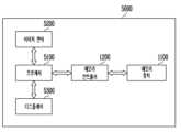
도 18을 참조하면, 메모리 시스템(5000)은 이미지 처리 장치, 예컨대 디지털 카메라, 디지털 카메라가 부착된 이동 전화기, 디지털 카메라가 부착된 스마트 폰, 또는 디지털 카메라가 부착된 태블릿 PC로 구현될 수 있다.Referring to FIG. 18 , the
메모리 시스템(5000)은 메모리 장치(Memory Device; 1100)와 상기 메모리 장치(1100)의 데이터 처리 동작, 예컨대 프로그램 동작, 소거 동작 또는 리드 동작을 제어할 수 있는 메모리 컨트롤러(1200)를 포함한다.The
메모리 시스템(5000)의 이미지 센서(Image Sensor; 5200)는 광학 이미지를 디지털 신호들로 변환할 수 있고, 변환된 디지털 신호들은 프로세서(Processor; 5100) 또는 메모리 컨트롤러(1200)로 전송될 수 있다. 프로세서(5100)의 제어에 따라, 상기 변환된 디지털 신호들은 디스플레이(Display; 5300)를 통하여 출력되거나 메모리 컨트롤러(1200)를 통하여 메모리 장치(1100)에 저장될 수 있다. 또한, 메모리 장치(1100)에 저장된 데이터는 프로세서(5100) 또는 메모리 컨트롤러(1200)의 제어에 따라 디스플레이(5300)를 통하여 출력될 수 있다.The
실시 예에 따라 메모리 장치(1100)의 동작을 제어할 수 있는 메모리 컨트롤러(1200)는 프로세서(5100)의 일부로서 구현되거나 프로세서(5100)와 별개의 칩으로 구현될 수 있다.According to embodiments, the
도 19는 도 3에 도시된 메모리 컨트롤러를 포함하는 메모리 시스템의 다른 실시 예를 설명하기 위한 도면이다.FIG. 19 is a diagram for explaining another embodiment of a memory system including the memory controller shown in FIG. 3 .
도 19를 참조하면, 메모리 시스템(Memory System; 7000)은 메모리 카드(memory card) 또는 스마트 카드(smart card)로 구현될 수 있다. 메모리 시스템(7000)은 메모리 장치(Memory Device; 1100), 메모리 컨트롤러(Memory Controller; 1200) 및 카드 인터페이스(Card Interface; 7100)를 포함할 수 있다.Referring to FIG. 19 , a memory system (7000) may be implemented as a memory card or a smart card. The
메모리 컨트롤러(1200)는 메모리 장치(1100)와 카드 인터페이스(7100) 사이에서 데이터의 교환을 제어할 수 있다. 실시 예에 따라, 카드 인터페이스(7100)는 SD(secure digital) 카드 인터페이스 또는 MMC(multi-media card) 인터페이스일 수 있으나 이에 한정되는 것은 아니다.The
카드 인터페이스(7100)는 호스트(HOST; 6000)의 프로토콜에 따라 호스트(6000)와 메모리 컨트롤러(1200) 사이에서 데이터 교환을 인터페이스할 수 있다. 실시 예에 따라 카드 인터페이스(7100)는 USB(Universal Serial Bus)프로토콜, IC(InterChip)-USB 프로토콜을 지원할 수 있다. 여기서, 카드 인터페이스는 호스트(6000)가 사용하는 프로토콜을 지원할 수 있는 하드웨어, 상기 하드웨어에 탑재된 소프트웨어 또는 신호 전송 방식을 의미할 수 있다.The
메모리 시스템(7000)이 PC, 태블릿 PC, 디지털 카메라, 디지털 오디오 플레이어, 이동 전화기, 콘솔 비디오 게임 하드웨어, 또는 디지털 셋-탑 박스와 같은 호스트(6000)의 호스트 인터페이스(6200)와 접속될 때, 호스트 인터페이스(6200)는 마이크로프로세서(Microprocessor; 6100)의 제어에 따라 카드 인터페이스(7100)와 메모리 컨트롤러(1200)를 통하여 메모리 장치(1100)와 데이터 통신을 수행할 수 있다.When the
본 발명의 상세한 설명에서는 구체적인 실시 예에 관하여 설명하였으나, 본 발명의 범위와 기술적 사상에서 벗어나지 않는 한도 내에서 다양한 변경이 가능하다. 그러므로 본 발명의 범위는 상술한 실시 예에 국한되어 정해져서는 안되며 후술하는 특허청구범위뿐만 아니라 이 발명의 특허청구범위와 균등한 것들에 의해 정해져야 한다.Although specific embodiments have been described in the detailed description of the present invention, various changes are possible within the limits that do not deviate from the scope and spirit of the present invention. Therefore, the scope of the present invention should not be limited to the above-described embodiments and should not be defined, but should be defined by those equivalent to the claims of this invention as well as the claims to be described later.
100: 메모리 셀 어레이110: 메모리 블록
200: 주변 회로210: 전압 생성 회로
220: 로우 디코더230: 페이지 버퍼 그룹
240: 컬럼 디코더250: 입출력 회로
260: 센싱 회로300: 제어 로직
400: 메인 메모리410: 버퍼 메모리
420: 버퍼 관리부421: 버퍼 모니터
423: 임계값 저장부425: 버퍼 용량 결정부
430: 제어부440: 데이터 변환부
450: 메모리 인터페이스100: memory cell array 110: memory block
200: peripheral circuit 210: voltage generation circuit
220: row decoder 230: page buffer group
240: column decoder 250: input/output circuit
260: sensing circuit 300: control logic
400: main memory 410: buffer memory
420: buffer management unit 421: buffer monitor
423: threshold storage unit 425: buffer capacity determination unit
430: control unit 440: data conversion unit
450: memory interface
Claims (22)
Translated fromKorean호스트로부터 수신되는 입력 데이터를 저장하는 입력 버퍼부 및 상기 메모리 장치로부터 수신되는 출력 데이터를 저장하는 출력 버퍼부를 포함하는 버퍼 메모리; 및
상기 입력 버퍼부 및 상기 출력 버퍼부 중 적어도 하나의 사용 상태를 확인하여, 상기 입력 버퍼부 및 상기 출력 버퍼부의 용량을 할당하는 버퍼 관리부를 포함하고,
상기 버퍼 관리부는,
상기 버퍼 메모리의 사용에 따른 버퍼 분석 데이터를 생성하는 버퍼 모니터;
상기 입력 버퍼부 및 상기 출력 버퍼부의 용량을 변경하기 위한 임계값을 저장하는 임계값 저장부; 및
상기 입력 버퍼부 또는 상기 출력 버퍼부 중 어느 하나가 사용 중인 용량이 상기 임계값을 초과한 횟수에 기초하여, 상기 입력 버퍼부 및 상기 출력 버퍼부에 할당된 용량을 변경할지 여부를 결정하는 버퍼 용량 결정부를 포함하는, 메모리 컨트롤러.As a memory controller that controls the operation of the memory device:
a buffer memory including an input buffer unit storing input data received from a host and an output buffer unit storing output data received from the memory device; and
A buffer management unit configured to check a usage state of at least one of the input buffer unit and the output buffer unit and allocate capacities of the input buffer unit and the output buffer unit;
The buffer management unit,
a buffer monitor generating buffer analysis data according to the use of the buffer memory;
a threshold value storage unit configured to store a threshold value for changing capacities of the input buffer unit and the output buffer unit; and
Buffer capacity for determining whether or not to change the capacity allocated to the input buffer unit and the output buffer unit based on the number of times that the capacity in use by any one of the input buffer unit and the output buffer unit exceeds the threshold value. A memory controller comprising a decision unit.
상기 버퍼 메모리는 에스램(SRAM)으로 구성되는 것을 특징으로 하는, 메모리 컨트롤러.According to claim 1,
The memory controller, characterized in that the buffer memory is composed of SRAM (SRAM).
상기 입력 버퍼부 및 상기 출력 버퍼부는 상기 버퍼 메모리의 특정 주소를 가리키는 버퍼 포인터에 의해 구분되고,
상기 버퍼 관리부는 상기 버퍼 포인터가 가리키는 위치를 변경하여, 상기 입력 버퍼부 및 상기 출력 버퍼부의 용량을 할당하는 것을 특징으로 하는, 메모리 컨트롤러.According to claim 1,
The input buffer unit and the output buffer unit are distinguished by a buffer pointer pointing to a specific address of the buffer memory,
The memory controller of claim 1 , wherein the buffer management unit allocates capacities of the input buffer unit and the output buffer unit by changing locations indicated by the buffer pointer.
상기 입력 버퍼부 및 상기 출력 버퍼부 중 어느 하나의 용량이 증가하면, 상기 입력 버퍼부 및 상기 출력 버퍼부 중 다른 하나의 용량이 감소하는 것을 특징으로 하는, 메모리 컨트롤러.The method of claim 3, as the location pointed to by the buffer pointer is changed,
When the capacity of one of the input buffer unit and the output buffer unit increases, the capacity of the other one of the input buffer unit and the output buffer unit decreases.
미리 결정된 제1 기간 동안 측정된 상기 제1 카운트 값이 상기 제1 임계 횟수와 같거나 이보다 큰 경우, 상기 버퍼 용량 결정부는 상기 입력 버퍼의 용량을 증가시킬 것을 결정하는 것을 특징으로 하는, 메모리 컨트롤러.5. The method of claim 4 , wherein the buffer analysis data includes a first count value, which is the number of times the amount of use of the input buffer unit exceeds a first predetermined threshold capacity, and the threshold value is a predetermined first threshold value for the input buffer. includes the number of times
The memory controller of claim 1 , wherein the buffer capacity determiner determines to increase the capacity of the input buffer when the first count value measured during the first predetermined period is equal to or greater than the first threshold number of times.
미리 결정된 제1 기간 동안 측정된 상기 제2 카운트 값이 상기 제2 임계 횟수와 같거나 이보다 큰 경우, 상기 버퍼 용량 결정부는 상기 출력 버퍼의 용량을 증가시킬 것을 결정하는 것을 특징으로 하는, 메모리 컨트롤러.5. The method of claim 4 , wherein the buffer analysis data includes a second count value, which is the number of times the amount of use of the output buffer unit exceeds a second predetermined threshold capacity, and the threshold value is a predetermined second threshold value for the output buffer. includes the number of times
When the second count value measured during the first predetermined period is equal to or greater than the second threshold number of times, the buffer capacity determining unit determines to increase the capacity of the output buffer.
미리 결정된 제1 기간 동안 측정된 상기 제1 카운트 값이 상기 제3 임계 횟수보다 작은 큰 경우, 상기 버퍼 용량 결정부는 상기 입력 버퍼의 용량을 감소시킬 것을 결정하는 것을 특징으로 하는, 메모리 컨트롤러.5. The method of claim 4 , wherein the buffer analysis data includes a first count value, which is the number of times the amount of use of the input buffer unit exceeds a first predetermined threshold capacity, and the threshold value is a third predetermined threshold value for the input buffer. includes the number of times
The memory controller of claim 1 , wherein the buffer capacity determination unit determines to reduce the capacity of the input buffer when the first count value measured during the first predetermined period is smaller than the third threshold number of times.
미리 결정된 제1 기간 동안 측정된 상기 제2 카운트 값이 상기 제4 임계 횟수보다 작은 큰 경우, 상기 버퍼 용량 결정부는 상기 출력 버퍼의 용량을 감소시킬 것을 결정하는 것을 특징으로 하는, 메모리 컨트롤러.5. The method of claim 4 , wherein the buffer analysis data includes a second count value, which is the number of times the amount of use of the output buffer unit exceeds a second predetermined threshold capacity, and the threshold value is a fourth predetermined threshold value for the output buffer. includes the number of times
The memory controller of claim 1 , wherein the buffer capacity determiner determines to reduce the capacity of the output buffer when the second count value measured during the first predetermined period is smaller than the fourth threshold number of times.
상기 총 용량이 상기 임계 누적 용량과 같거나 이보다 큰 경우, 상기 버퍼 용량 결정부는 상기 입력 버퍼의 용량을 증가시킬 것으로 결정하는 것을 특징으로 하는, 메모리 컨트롤러.The method of claim 4 , wherein the buffer analysis data includes a total capacity of data stored in the input buffer unit, and the threshold value includes a predetermined threshold cumulative capacity of the input buffer unit,
When the total capacity is equal to or greater than the threshold cumulative capacity, the buffer capacity determining unit determines to increase the capacity of the input buffer.
상기 총 용량이 상기 임계 누적 용량과 같거나 이보다 큰 경우, 상기 버퍼 용량 결정부는 상기 출력 버퍼의 용량을 증가시킬 것으로 결정하는 것을 특징으로 하는, 메모리 컨트롤러.The method of claim 4, wherein the buffer analysis data includes a total capacity of data stored in the output buffer unit, and the threshold value includes a predetermined threshold cumulative capacity for the output buffer unit,
When the total capacity is equal to or greater than the threshold cumulative capacity, the buffer capacity determining unit determines to increase the capacity of the output buffer.
상기 메모리 컨트롤러 내 버퍼 메모리의 입력 버퍼부와 출력 버퍼부가 사용 중인 용량을 식별하는 단계;
상기 입력 버퍼부 및 출력 버퍼부가 사용 중인 용량을 미리 결정된 제1 임계 용량 및 미리 결정된 제2 임계 용량을 포함하는 임계 용량들과 비교하는 단계;
제1 카운트 값 및 제2 카운트 값을 포함하는 카운트 값들을 생성하는 단계; 및
상기 카운트 값들에 기초하여, 상기 입력 버퍼부와 상기 출력 버퍼부의 용량을 조절하는 단계를 포함하고,
상기 제1 카운트 값은 상기 입력 버퍼부가 사용 중인 용량이 상기 제1 임계 용량을 초과한 횟수이고,
상기 제2 카운트 값은 상기 출력 버퍼부가 사용중인 용량이 상기 제2 임계 용량을 초과한 횟수인, 메모리 컨트롤러의 동작 방법.A method of operating a memory controller for controlling an operation of a memory device, comprising:
identifying the capacity being used by an input buffer unit and an output buffer unit of a buffer memory in the memory controller;
comparing the capacity in use of the input buffer unit and the output buffer unit with threshold capacities including a first predetermined threshold capacity and a predetermined second threshold capacity;
generating count values including a first count value and a second count value; and
Adjusting capacities of the input buffer unit and the output buffer unit based on the count values;
The first count value is the number of times the capacity being used by the input buffer unit exceeds the first threshold capacity;
The second count value is the number of times the capacity being used by the output buffer unit exceeds the second threshold capacity.
상기 제1 카운트 값이 미리 결정된 제1 임계 횟수보다 크거나 같은지 여부를 판단하는 단계를 포함하고,
상기 입력 버퍼부와 상기 출력 버퍼부의 용량을 조절하는 단계에서는, 상기 제1 카운트 값이 상기 제1 임계 횟수보다 크거나 같은 경우 상기 입력 버퍼부의 용량을 증가시키는 것을 특징으로 하는, 메모리 컨트롤러의 동작 방법.16. The method of claim 15, wherein adjusting capacities of the input buffer unit and the output buffer unit:
Determining whether the first count value is greater than or equal to a first predetermined threshold number of times;
In the step of adjusting the capacities of the input buffer unit and the output buffer unit, the capacity of the input buffer unit is increased when the first count value is greater than or equal to the first threshold number of times. .
상기 제2 카운트 값이 미리 결정된 제2 임계 횟수보다 크거나 같은지 여부를 판단하는 단계를 포함하고,
상기 입력 버퍼부와 상기 출력 버퍼부의 용량을 조절하는 단계에서는, 상기 제2 카운트 값이 상기 제2 임계 횟수보다 크거나 같은 경우 상기 출력 버퍼부의 용량을 증가시키는 것을 특징으로 하는, 메모리 컨트롤러의 동작 방법.16. The method of claim 15, wherein adjusting capacities of the input buffer unit and the output buffer unit:
Determining whether the second count value is greater than or equal to a predetermined second threshold number of times;
In the step of adjusting the capacities of the input buffer unit and the output buffer unit, the capacity of the output buffer unit is increased when the second count value is greater than or equal to the second threshold number of times. .
Priority Applications (4)
| Application Number | Priority Date | Filing Date | Title |
|---|---|---|---|
| KR1020180018291AKR102521298B1 (en) | 2018-02-14 | 2018-02-14 | Memory controller and operating method thereof |
| US16/148,385US10795614B2 (en) | 2018-02-14 | 2018-10-01 | Memory controller and operating method thereof |
| CN201811256559.5ACN110162489B (en) | 2018-02-14 | 2018-10-26 | Memory controller and method of operation of the memory controller |
| US17/037,992US11403045B2 (en) | 2018-02-14 | 2020-09-30 | Memory controller and operating method thereof |
Applications Claiming Priority (1)
| Application Number | Priority Date | Filing Date | Title |
|---|---|---|---|
| KR1020180018291AKR102521298B1 (en) | 2018-02-14 | 2018-02-14 | Memory controller and operating method thereof |
Publications (2)
| Publication Number | Publication Date |
|---|---|
| KR20190098394A KR20190098394A (en) | 2019-08-22 |
| KR102521298B1true KR102521298B1 (en) | 2023-04-14 |
Family
ID=67541643
Family Applications (1)
| Application Number | Title | Priority Date | Filing Date |
|---|---|---|---|
| KR1020180018291AActiveKR102521298B1 (en) | 2018-02-14 | 2018-02-14 | Memory controller and operating method thereof |
Country Status (3)
| Country | Link |
|---|---|
| US (2) | US10795614B2 (en) |
| KR (1) | KR102521298B1 (en) |
| CN (1) | CN110162489B (en) |
Families Citing this family (8)
| Publication number | Priority date | Publication date | Assignee | Title |
|---|---|---|---|---|
| KR102521298B1 (en)* | 2018-02-14 | 2023-04-14 | 에스케이하이닉스 주식회사 | Memory controller and operating method thereof |
| KR102125362B1 (en)* | 2019-08-12 | 2020-06-22 | 푸드리퍼블릭코리아 유한회사 | Black curry and method thereof |
| US11416168B2 (en) | 2019-11-07 | 2022-08-16 | FADU Inc. | Memory controller and storage device including the same |
| KR102266166B1 (en)* | 2019-11-07 | 2021-06-17 | 주식회사 파두 | Memory controller and storage device including the same |
| KR20220063648A (en)* | 2020-11-10 | 2022-05-17 | 에스케이하이닉스 주식회사 | Memory device, storage device and operating method of memory controller |
| KR20220120016A (en) | 2021-02-22 | 2022-08-30 | 에스케이하이닉스 주식회사 | Memory controller and operating method thereof |
| US20220317898A1 (en)* | 2021-04-03 | 2022-10-06 | EMC IP Holding Company LLC | Managing Application Storage Resource Allocations Based on Application Specific Storage Policies |
| CN115061959B (en)* | 2022-08-17 | 2022-10-25 | 深圳比特微电子科技有限公司 | Data interaction method, apparatus, system, electronic device and storage medium |
Citations (2)
| Publication number | Priority date | Publication date | Assignee | Title |
|---|---|---|---|---|
| US20070130401A1 (en)* | 1998-10-14 | 2007-06-07 | David Baker | Integrated multimedia system |
| US20130013825A1 (en)* | 2011-07-07 | 2013-01-10 | Renesas Electronics Corporation | Usb device controller and power control method thereof |
Family Cites Families (17)
| Publication number | Priority date | Publication date | Assignee | Title |
|---|---|---|---|---|
| US5133062A (en)* | 1986-03-06 | 1992-07-21 | Advanced Micro Devices, Inc. | RAM buffer controller for providing simulated first-in-first-out (FIFO) buffers in a random access memory |
| US5754764A (en)* | 1994-02-22 | 1998-05-19 | National Semiconductor Corp. | Combination of input output circuitry and local area network systems |
| US5818539A (en)* | 1996-03-29 | 1998-10-06 | Matsushita Electric Corporation Of America | System and method for updating a system time constant (STC) counter following a discontinuity in an MPEG-2 transport data stream |
| US6094695A (en)* | 1998-03-11 | 2000-07-25 | Texas Instruments Incorporated | Storage buffer that dynamically adjusts boundary between two storage areas when one area is full and the other has an empty data register |
| US6473818B1 (en)* | 1998-09-09 | 2002-10-29 | Advanced Micro Devices, Inc. | Apparatus and method in a network interface device for asynchronously generating SRAM full and empty flags using coded read and write pointer values |
| WO2001009710A1 (en)* | 1999-07-28 | 2001-02-08 | Infineon Technologies Ag | Method and device for writing and reading a buffer memory |
| US6678813B1 (en)* | 1999-10-28 | 2004-01-13 | Hewlett-Packard Development Company, L.P. | Dynamically adaptive buffer mechanism |
| US7080169B2 (en) | 2001-12-11 | 2006-07-18 | Emulex Design & Manufacturing Corporation | Receiving data from interleaved multiple concurrent transactions in a FIFO memory having programmable buffer zones |
| CN101162919B (en)* | 2006-10-11 | 2011-01-05 | 中兴通讯股份有限公司 | Data caching circuit |
| JP4950796B2 (en)* | 2007-07-31 | 2012-06-13 | 株式会社東芝 | Semiconductor device |
| KR100947618B1 (en)* | 2008-08-27 | 2010-03-15 | 한국전자통신연구원 | Data processing systems |
| KR101544705B1 (en)* | 2008-12-29 | 2015-08-17 | 연세대학교 산학협력단 | A victim system detection device, a victim system detection method, a communication device, and a communication method |
| US20130242186A1 (en)* | 2012-03-14 | 2013-09-19 | Samsung Electronics Co., Ltd. | Image processing apparatus and control method thereof |
| KR20140030962A (en)* | 2012-09-04 | 2014-03-12 | 에스케이하이닉스 주식회사 | Data storage device and operating method thereof |
| KR20160144577A (en) | 2015-06-08 | 2016-12-19 | 삼성전자주식회사 | Nonvolatile memory module and user device comprising the same |
| US10346324B2 (en)* | 2017-02-13 | 2019-07-09 | Microchip Technology Incorporated | Devices and methods for autonomous hardware management of circular buffers |
| KR102521298B1 (en)* | 2018-02-14 | 2023-04-14 | 에스케이하이닉스 주식회사 | Memory controller and operating method thereof |
- 2018
- 2018-02-14KRKR1020180018291Apatent/KR102521298B1/enactiveActive
- 2018-10-01USUS16/148,385patent/US10795614B2/enactiveActive
- 2018-10-26CNCN201811256559.5Apatent/CN110162489B/enactiveActive
- 2020
- 2020-09-30USUS17/037,992patent/US11403045B2/enactiveActive
Patent Citations (2)
| Publication number | Priority date | Publication date | Assignee | Title |
|---|---|---|---|---|
| US20070130401A1 (en)* | 1998-10-14 | 2007-06-07 | David Baker | Integrated multimedia system |
| US20130013825A1 (en)* | 2011-07-07 | 2013-01-10 | Renesas Electronics Corporation | Usb device controller and power control method thereof |
Also Published As
| Publication number | Publication date |
|---|---|
| US11403045B2 (en) | 2022-08-02 |
| CN110162489A (en) | 2019-08-23 |
| KR20190098394A (en) | 2019-08-22 |
| US20210011668A1 (en) | 2021-01-14 |
| CN110162489B (en) | 2023-06-27 |
| US10795614B2 (en) | 2020-10-06 |
| US20190250858A1 (en) | 2019-08-15 |
Similar Documents
| Publication | Publication Date | Title |
|---|---|---|
| KR102521298B1 (en) | Memory controller and operating method thereof | |
| US20230009365A1 (en) | Data storage device and operating method thereof | |
| US11094364B2 (en) | Data storage device and operating method thereof | |
| US11061608B2 (en) | Memory controller and memory system having the same | |
| KR102840980B1 (en) | Memory system for determining usage of buffer based on i/o throughput and operation method thereof | |
| US10324645B2 (en) | Data storage device and data storage method thereof | |
| KR20150002069A (en) | Memory controller, and operation method of the memory controller | |
| KR20120103274A (en) | Non-volatile memory device and read method thereof | |
| US10698830B2 (en) | Obtaining data in a nonvolatile memory device through the use of descriptors | |
| US10878924B2 (en) | Data storage device intergrating host read commands and method of operating the same | |
| KR20210098717A (en) | Controller, operating method thereof and storage device including the same | |
| CN107818808A (en) | Data writing method, memory control circuit unit and memory storage device | |
| KR20230126036A (en) | An operating method of a storage controller and a storage system thereof | |
| US20190354483A1 (en) | Controller and memory system including the same | |
| US11126379B2 (en) | Memory system | |
| US12436706B2 (en) | Storage device and operating method of storage device | |
| KR20190099879A (en) | Memory controller and operating method thereof | |
| US11194512B2 (en) | Data storage device which selectively performs a cache read or a normal read operation depending on work load and operating method thereof | |
| US10515693B1 (en) | Data storage apparatus and operating method thereof | |
| US20250181450A1 (en) | Memory device, memory controller, and storage device including the same | |
| US20220156184A1 (en) | Memory system | |
| US20210397558A1 (en) | Storage device and operating method thereof | |
| US10929055B2 (en) | Memory system and operating method thereof | |
| US11403038B2 (en) | Controller, a memory system including the controller, and method of operating the controller | |
| US10628322B2 (en) | Memory system and operating method thereof |
Legal Events
| Date | Code | Title | Description |
|---|---|---|---|
| PA0109 | Patent application | St.27 status event code:A-0-1-A10-A12-nap-PA0109 | |
| R17-X000 | Change to representative recorded | St.27 status event code:A-3-3-R10-R17-oth-X000 | |
| PG1501 | Laying open of application | St.27 status event code:A-1-1-Q10-Q12-nap-PG1501 | |
| A201 | Request for examination | ||
| PA0201 | Request for examination | St.27 status event code:A-1-2-D10-D11-exm-PA0201 | |
| R17-X000 | Change to representative recorded | St.27 status event code:A-3-3-R10-R17-oth-X000 | |
| E902 | Notification of reason for refusal | ||
| PE0902 | Notice of grounds for rejection | St.27 status event code:A-1-2-D10-D21-exm-PE0902 | |
| AMND | Amendment | ||
| E13-X000 | Pre-grant limitation requested | St.27 status event code:A-2-3-E10-E13-lim-X000 | |
| P11-X000 | Amendment of application requested | St.27 status event code:A-2-2-P10-P11-nap-X000 | |
| P13-X000 | Application amended | St.27 status event code:A-2-2-P10-P13-nap-X000 | |
| E601 | Decision to refuse application | ||
| PE0601 | Decision on rejection of patent | St.27 status event code:N-2-6-B10-B15-exm-PE0601 | |
| AMND | Amendment | ||
| E13-X000 | Pre-grant limitation requested | St.27 status event code:A-2-3-E10-E13-lim-X000 | |
| P11-X000 | Amendment of application requested | St.27 status event code:A-2-2-P10-P11-nap-X000 | |
| P13-X000 | Application amended | St.27 status event code:A-2-2-P10-P13-nap-X000 | |
| PX0901 | Re-examination | St.27 status event code:A-2-3-E10-E12-rex-PX0901 | |
| PX0701 | Decision of registration after re-examination | St.27 status event code:A-3-4-F10-F13-rex-PX0701 | |
| X701 | Decision to grant (after re-examination) | ||
| GRNT | Written decision to grant | ||
| PR0701 | Registration of establishment | St.27 status event code:A-2-4-F10-F11-exm-PR0701 | |
| PR1002 | Payment of registration fee | St.27 status event code:A-2-2-U10-U11-oth-PR1002 Fee payment year number:1 | |
| PG1601 | Publication of registration | St.27 status event code:A-4-4-Q10-Q13-nap-PG1601 |