KR102521019B1 - Refrigerator - Google Patents
RefrigeratorDownload PDFInfo
- Publication number
- KR102521019B1 KR102521019B1KR1020180028119AKR20180028119AKR102521019B1KR 102521019 B1KR102521019 B1KR 102521019B1KR 1020180028119 AKR1020180028119 AKR 1020180028119AKR 20180028119 AKR20180028119 AKR 20180028119AKR 102521019 B1KR102521019 B1KR 102521019B1
- Authority
- KR
- South Korea
- Prior art keywords
- temperature
- pin
- cooling
- sensor
- fan
- Prior art date
- Legal status (The legal status is an assumption and is not a legal conclusion. Google has not performed a legal analysis and makes no representation as to the accuracy of the status listed.)
- Active
Links
Images


Classifications
- F—MECHANICAL ENGINEERING; LIGHTING; HEATING; WEAPONS; BLASTING
- F25—REFRIGERATION OR COOLING; COMBINED HEATING AND REFRIGERATION SYSTEMS; HEAT PUMP SYSTEMS; MANUFACTURE OR STORAGE OF ICE; LIQUEFACTION SOLIDIFICATION OF GASES
- F25B—REFRIGERATION MACHINES, PLANTS OR SYSTEMS; COMBINED HEATING AND REFRIGERATION SYSTEMS; HEAT PUMP SYSTEMS
- F25B21/00—Machines, plants or systems, using electric or magnetic effects
- F25B21/02—Machines, plants or systems, using electric or magnetic effects using Peltier effect; using Nernst-Ettinghausen effect
- F25B21/04—Machines, plants or systems, using electric or magnetic effects using Peltier effect; using Nernst-Ettinghausen effect reversible
- F—MECHANICAL ENGINEERING; LIGHTING; HEATING; WEAPONS; BLASTING
- F25—REFRIGERATION OR COOLING; COMBINED HEATING AND REFRIGERATION SYSTEMS; HEAT PUMP SYSTEMS; MANUFACTURE OR STORAGE OF ICE; LIQUEFACTION SOLIDIFICATION OF GASES
- F25B—REFRIGERATION MACHINES, PLANTS OR SYSTEMS; COMBINED HEATING AND REFRIGERATION SYSTEMS; HEAT PUMP SYSTEMS
- F25B21/00—Machines, plants or systems, using electric or magnetic effects
- F25B21/02—Machines, plants or systems, using electric or magnetic effects using Peltier effect; using Nernst-Ettinghausen effect
- F—MECHANICAL ENGINEERING; LIGHTING; HEATING; WEAPONS; BLASTING
- F25—REFRIGERATION OR COOLING; COMBINED HEATING AND REFRIGERATION SYSTEMS; HEAT PUMP SYSTEMS; MANUFACTURE OR STORAGE OF ICE; LIQUEFACTION SOLIDIFICATION OF GASES
- F25B—REFRIGERATION MACHINES, PLANTS OR SYSTEMS; COMBINED HEATING AND REFRIGERATION SYSTEMS; HEAT PUMP SYSTEMS
- F25B47/00—Arrangements for preventing or removing deposits or corrosion, not provided for in another subclass
- F25B47/02—Defrosting cycles
- F—MECHANICAL ENGINEERING; LIGHTING; HEATING; WEAPONS; BLASTING
- F25—REFRIGERATION OR COOLING; COMBINED HEATING AND REFRIGERATION SYSTEMS; HEAT PUMP SYSTEMS; MANUFACTURE OR STORAGE OF ICE; LIQUEFACTION SOLIDIFICATION OF GASES
- F25D—REFRIGERATORS; COLD ROOMS; ICE-BOXES; COOLING OR FREEZING APPARATUS NOT OTHERWISE PROVIDED FOR
- F25D11/00—Self-contained movable devices, e.g. domestic refrigerators
- F—MECHANICAL ENGINEERING; LIGHTING; HEATING; WEAPONS; BLASTING
- F25—REFRIGERATION OR COOLING; COMBINED HEATING AND REFRIGERATION SYSTEMS; HEAT PUMP SYSTEMS; MANUFACTURE OR STORAGE OF ICE; LIQUEFACTION SOLIDIFICATION OF GASES
- F25D—REFRIGERATORS; COLD ROOMS; ICE-BOXES; COOLING OR FREEZING APPARATUS NOT OTHERWISE PROVIDED FOR
- F25D15/00—Devices not covered by group F25D11/00 or F25D13/00, e.g. non-self-contained movable devices
- F—MECHANICAL ENGINEERING; LIGHTING; HEATING; WEAPONS; BLASTING
- F25—REFRIGERATION OR COOLING; COMBINED HEATING AND REFRIGERATION SYSTEMS; HEAT PUMP SYSTEMS; MANUFACTURE OR STORAGE OF ICE; LIQUEFACTION SOLIDIFICATION OF GASES
- F25D—REFRIGERATORS; COLD ROOMS; ICE-BOXES; COOLING OR FREEZING APPARATUS NOT OTHERWISE PROVIDED FOR
- F25D17/00—Arrangements for circulating cooling fluids; Arrangements for circulating gas, e.g. air, within refrigerated spaces
- F25D17/04—Arrangements for circulating cooling fluids; Arrangements for circulating gas, e.g. air, within refrigerated spaces for circulating air, e.g. by convection
- F25D17/042—Air treating means within refrigerated spaces
- F—MECHANICAL ENGINEERING; LIGHTING; HEATING; WEAPONS; BLASTING
- F25—REFRIGERATION OR COOLING; COMBINED HEATING AND REFRIGERATION SYSTEMS; HEAT PUMP SYSTEMS; MANUFACTURE OR STORAGE OF ICE; LIQUEFACTION SOLIDIFICATION OF GASES
- F25D—REFRIGERATORS; COLD ROOMS; ICE-BOXES; COOLING OR FREEZING APPARATUS NOT OTHERWISE PROVIDED FOR
- F25D17/00—Arrangements for circulating cooling fluids; Arrangements for circulating gas, e.g. air, within refrigerated spaces
- F25D17/04—Arrangements for circulating cooling fluids; Arrangements for circulating gas, e.g. air, within refrigerated spaces for circulating air, e.g. by convection
- F25D17/06—Arrangements for circulating cooling fluids; Arrangements for circulating gas, e.g. air, within refrigerated spaces for circulating air, e.g. by convection by forced circulation
- F25D17/062—Arrangements for circulating cooling fluids; Arrangements for circulating gas, e.g. air, within refrigerated spaces for circulating air, e.g. by convection by forced circulation in household refrigerators
- F—MECHANICAL ENGINEERING; LIGHTING; HEATING; WEAPONS; BLASTING
- F25—REFRIGERATION OR COOLING; COMBINED HEATING AND REFRIGERATION SYSTEMS; HEAT PUMP SYSTEMS; MANUFACTURE OR STORAGE OF ICE; LIQUEFACTION SOLIDIFICATION OF GASES
- F25D—REFRIGERATORS; COLD ROOMS; ICE-BOXES; COOLING OR FREEZING APPARATUS NOT OTHERWISE PROVIDED FOR
- F25D21/00—Defrosting; Preventing frosting; Removing condensed or defrost water
- F25D21/002—Defroster control
- F25D21/004—Control mechanisms
- F—MECHANICAL ENGINEERING; LIGHTING; HEATING; WEAPONS; BLASTING
- F25—REFRIGERATION OR COOLING; COMBINED HEATING AND REFRIGERATION SYSTEMS; HEAT PUMP SYSTEMS; MANUFACTURE OR STORAGE OF ICE; LIQUEFACTION SOLIDIFICATION OF GASES
- F25D—REFRIGERATORS; COLD ROOMS; ICE-BOXES; COOLING OR FREEZING APPARATUS NOT OTHERWISE PROVIDED FOR
- F25D21/00—Defrosting; Preventing frosting; Removing condensed or defrost water
- F25D21/002—Defroster control
- F25D21/006—Defroster control with electronic control circuits
- F—MECHANICAL ENGINEERING; LIGHTING; HEATING; WEAPONS; BLASTING
- F25—REFRIGERATION OR COOLING; COMBINED HEATING AND REFRIGERATION SYSTEMS; HEAT PUMP SYSTEMS; MANUFACTURE OR STORAGE OF ICE; LIQUEFACTION SOLIDIFICATION OF GASES
- F25D—REFRIGERATORS; COLD ROOMS; ICE-BOXES; COOLING OR FREEZING APPARATUS NOT OTHERWISE PROVIDED FOR
- F25D21/00—Defrosting; Preventing frosting; Removing condensed or defrost water
- F25D21/06—Removing frost
- F25D21/08—Removing frost by electric heating
- F—MECHANICAL ENGINEERING; LIGHTING; HEATING; WEAPONS; BLASTING
- F25—REFRIGERATION OR COOLING; COMBINED HEATING AND REFRIGERATION SYSTEMS; HEAT PUMP SYSTEMS; MANUFACTURE OR STORAGE OF ICE; LIQUEFACTION SOLIDIFICATION OF GASES
- F25D—REFRIGERATORS; COLD ROOMS; ICE-BOXES; COOLING OR FREEZING APPARATUS NOT OTHERWISE PROVIDED FOR
- F25D29/00—Arrangement or mounting of control or safety devices
- F—MECHANICAL ENGINEERING; LIGHTING; HEATING; WEAPONS; BLASTING
- F25—REFRIGERATION OR COOLING; COMBINED HEATING AND REFRIGERATION SYSTEMS; HEAT PUMP SYSTEMS; MANUFACTURE OR STORAGE OF ICE; LIQUEFACTION SOLIDIFICATION OF GASES
- F25B—REFRIGERATION MACHINES, PLANTS OR SYSTEMS; COMBINED HEATING AND REFRIGERATION SYSTEMS; HEAT PUMP SYSTEMS
- F25B2321/00—Details of machines, plants or systems, using electric or magnetic effects
- F25B2321/02—Details of machines, plants or systems, using electric or magnetic effects using Peltier effects; using Nernst-Ettinghausen effects
- F25B2321/021—Control thereof
- F25B2321/0211—Control thereof of fans
- F—MECHANICAL ENGINEERING; LIGHTING; HEATING; WEAPONS; BLASTING
- F25—REFRIGERATION OR COOLING; COMBINED HEATING AND REFRIGERATION SYSTEMS; HEAT PUMP SYSTEMS; MANUFACTURE OR STORAGE OF ICE; LIQUEFACTION SOLIDIFICATION OF GASES
- F25B—REFRIGERATION MACHINES, PLANTS OR SYSTEMS; COMBINED HEATING AND REFRIGERATION SYSTEMS; HEAT PUMP SYSTEMS
- F25B2321/00—Details of machines, plants or systems, using electric or magnetic effects
- F25B2321/02—Details of machines, plants or systems, using electric or magnetic effects using Peltier effects; using Nernst-Ettinghausen effects
- F25B2321/021—Control thereof
- F25B2321/0212—Control thereof of electric power, current or voltage
- F—MECHANICAL ENGINEERING; LIGHTING; HEATING; WEAPONS; BLASTING
- F25—REFRIGERATION OR COOLING; COMBINED HEATING AND REFRIGERATION SYSTEMS; HEAT PUMP SYSTEMS; MANUFACTURE OR STORAGE OF ICE; LIQUEFACTION SOLIDIFICATION OF GASES
- F25B—REFRIGERATION MACHINES, PLANTS OR SYSTEMS; COMBINED HEATING AND REFRIGERATION SYSTEMS; HEAT PUMP SYSTEMS
- F25B2321/00—Details of machines, plants or systems, using electric or magnetic effects
- F25B2321/02—Details of machines, plants or systems, using electric or magnetic effects using Peltier effects; using Nernst-Ettinghausen effects
- F25B2321/023—Mounting details thereof
- F—MECHANICAL ENGINEERING; LIGHTING; HEATING; WEAPONS; BLASTING
- F25—REFRIGERATION OR COOLING; COMBINED HEATING AND REFRIGERATION SYSTEMS; HEAT PUMP SYSTEMS; MANUFACTURE OR STORAGE OF ICE; LIQUEFACTION SOLIDIFICATION OF GASES
- F25B—REFRIGERATION MACHINES, PLANTS OR SYSTEMS; COMBINED HEATING AND REFRIGERATION SYSTEMS; HEAT PUMP SYSTEMS
- F25B2321/00—Details of machines, plants or systems, using electric or magnetic effects
- F25B2321/02—Details of machines, plants or systems, using electric or magnetic effects using Peltier effects; using Nernst-Ettinghausen effects
- F25B2321/025—Removal of heat
- F25B2321/0251—Removal of heat by a gas
- F—MECHANICAL ENGINEERING; LIGHTING; HEATING; WEAPONS; BLASTING
- F25—REFRIGERATION OR COOLING; COMBINED HEATING AND REFRIGERATION SYSTEMS; HEAT PUMP SYSTEMS; MANUFACTURE OR STORAGE OF ICE; LIQUEFACTION SOLIDIFICATION OF GASES
- F25B—REFRIGERATION MACHINES, PLANTS OR SYSTEMS; COMBINED HEATING AND REFRIGERATION SYSTEMS; HEAT PUMP SYSTEMS
- F25B2600/00—Control issues
- F25B2600/23—Time delays
- F—MECHANICAL ENGINEERING; LIGHTING; HEATING; WEAPONS; BLASTING
- F25—REFRIGERATION OR COOLING; COMBINED HEATING AND REFRIGERATION SYSTEMS; HEAT PUMP SYSTEMS; MANUFACTURE OR STORAGE OF ICE; LIQUEFACTION SOLIDIFICATION OF GASES
- F25B—REFRIGERATION MACHINES, PLANTS OR SYSTEMS; COMBINED HEATING AND REFRIGERATION SYSTEMS; HEAT PUMP SYSTEMS
- F25B2700/00—Sensing or detecting of parameters; Sensors therefor
- F25B2700/21—Temperatures
- F25B2700/2104—Temperatures of an indoor room or compartment
- F—MECHANICAL ENGINEERING; LIGHTING; HEATING; WEAPONS; BLASTING
- F25—REFRIGERATION OR COOLING; COMBINED HEATING AND REFRIGERATION SYSTEMS; HEAT PUMP SYSTEMS; MANUFACTURE OR STORAGE OF ICE; LIQUEFACTION SOLIDIFICATION OF GASES
- F25B—REFRIGERATION MACHINES, PLANTS OR SYSTEMS; COMBINED HEATING AND REFRIGERATION SYSTEMS; HEAT PUMP SYSTEMS
- F25B2700/00—Sensing or detecting of parameters; Sensors therefor
- F25B2700/21—Temperatures
- F25B2700/2106—Temperatures of fresh outdoor air
- F—MECHANICAL ENGINEERING; LIGHTING; HEATING; WEAPONS; BLASTING
- F25—REFRIGERATION OR COOLING; COMBINED HEATING AND REFRIGERATION SYSTEMS; HEAT PUMP SYSTEMS; MANUFACTURE OR STORAGE OF ICE; LIQUEFACTION SOLIDIFICATION OF GASES
- F25D—REFRIGERATORS; COLD ROOMS; ICE-BOXES; COOLING OR FREEZING APPARATUS NOT OTHERWISE PROVIDED FOR
- F25D2317/00—Details or arrangements for circulating cooling fluids; Details or arrangements for circulating gas, e.g. air, within refrigerated spaces, not provided for in other groups of this subclass
- F25D2317/04—Treating air flowing to refrigeration compartments
- F25D2317/041—Treating air flowing to refrigeration compartments by purification
- F25D2317/0411—Treating air flowing to refrigeration compartments by purification by dehumidification
- F—MECHANICAL ENGINEERING; LIGHTING; HEATING; WEAPONS; BLASTING
- F25—REFRIGERATION OR COOLING; COMBINED HEATING AND REFRIGERATION SYSTEMS; HEAT PUMP SYSTEMS; MANUFACTURE OR STORAGE OF ICE; LIQUEFACTION SOLIDIFICATION OF GASES
- F25D—REFRIGERATORS; COLD ROOMS; ICE-BOXES; COOLING OR FREEZING APPARATUS NOT OTHERWISE PROVIDED FOR
- F25D2317/00—Details or arrangements for circulating cooling fluids; Details or arrangements for circulating gas, e.g. air, within refrigerated spaces, not provided for in other groups of this subclass
- F25D2317/06—Details or arrangements for circulating cooling fluids; Details or arrangements for circulating gas, e.g. air, within refrigerated spaces, not provided for in other groups of this subclass with forced air circulation
- F25D2317/068—Details or arrangements for circulating cooling fluids; Details or arrangements for circulating gas, e.g. air, within refrigerated spaces, not provided for in other groups of this subclass with forced air circulation characterised by the fans
- F25D2317/0682—Two or more fans
- F—MECHANICAL ENGINEERING; LIGHTING; HEATING; WEAPONS; BLASTING
- F25—REFRIGERATION OR COOLING; COMBINED HEATING AND REFRIGERATION SYSTEMS; HEAT PUMP SYSTEMS; MANUFACTURE OR STORAGE OF ICE; LIQUEFACTION SOLIDIFICATION OF GASES
- F25D—REFRIGERATORS; COLD ROOMS; ICE-BOXES; COOLING OR FREEZING APPARATUS NOT OTHERWISE PROVIDED FOR
- F25D2600/00—Control issues
- F25D2600/02—Timing
- F—MECHANICAL ENGINEERING; LIGHTING; HEATING; WEAPONS; BLASTING
- F25—REFRIGERATION OR COOLING; COMBINED HEATING AND REFRIGERATION SYSTEMS; HEAT PUMP SYSTEMS; MANUFACTURE OR STORAGE OF ICE; LIQUEFACTION SOLIDIFICATION OF GASES
- F25D—REFRIGERATORS; COLD ROOMS; ICE-BOXES; COOLING OR FREEZING APPARATUS NOT OTHERWISE PROVIDED FOR
- F25D2700/00—Means for sensing or measuring; Sensors therefor
- F25D2700/12—Sensors measuring the inside temperature
- F—MECHANICAL ENGINEERING; LIGHTING; HEATING; WEAPONS; BLASTING
- F25—REFRIGERATION OR COOLING; COMBINED HEATING AND REFRIGERATION SYSTEMS; HEAT PUMP SYSTEMS; MANUFACTURE OR STORAGE OF ICE; LIQUEFACTION SOLIDIFICATION OF GASES
- F25D—REFRIGERATORS; COLD ROOMS; ICE-BOXES; COOLING OR FREEZING APPARATUS NOT OTHERWISE PROVIDED FOR
- F25D2700/00—Means for sensing or measuring; Sensors therefor
- F25D2700/14—Sensors measuring the temperature outside the refrigerator or freezer
Landscapes
- Engineering & Computer Science (AREA)
- Physics & Mathematics (AREA)
- Mechanical Engineering (AREA)
- Thermal Sciences (AREA)
- General Engineering & Computer Science (AREA)
- Chemical & Material Sciences (AREA)
- Combustion & Propulsion (AREA)
- Devices That Are Associated With Refrigeration Equipment (AREA)
- Defrosting Systems (AREA)
Abstract
Translated fromKoreanDescription
Translated fromKorean본 발명은 열전소자모듈을 구비하여 저소음으로 높은 냉장 성능을 나타내는 냉장고에 관한 것이다.The present invention relates to a refrigerator having a thermoelectric module and exhibiting high refrigerating performance with low noise.
열전소자는 펠티어 효과(Peltier Effect)를 이용하여 흡열과 발열을 구현하는 소자를 가리킨다. 펠티어 효과는 소자의 양 단에 전압을 인가하면, 전류의 방향에 따라 한쪽 면에서는 흡열 현상이 발생하고, 반대쪽 면에서는 발열 현상이 일어나는 효과를 가리킨다. 이 열전소자는 냉동사이클 장치 대신 냉장고에 이용될 수 있다.A thermoelectric device refers to a device that implements heat absorption and heat generation by using the Peltier Effect. The Peltier effect refers to an effect in which, when a voltage is applied to both ends of a device, an endothermic phenomenon occurs on one side and an exothermic phenomenon occurs on the other side, depending on the direction of the current. This thermoelectric element can be used in a refrigerator instead of a refrigerating cycle device.
일반적으로 냉장고는 내부에 단열재로 충전된 캐비닛과 도어에 의해, 외부에서 침투하는 열을 차단 가능한 식품 저장공간을 형성한다. 또한, 상기 냉장고는 상기 식품 저장공간 내부의 열을 흡수하는 증발기와 상기 식품저장공간 외부로 수집된 열을 배출하는 방열장치로 구성된 냉동장치를 구비한다. 상기 냉장고는, 상기 냉동장치를 이용하여 상기 식품 저장공간을 미생물의 생존 및 증식이 어려운 저온의 온도영역으로 유지하여, 저장된 식품을 장기간 변질 없이 보관한다.In general, a refrigerator forms a food storage space capable of blocking heat penetrating from the outside by a cabinet and a door filled with an insulating material therein. In addition, the refrigerator includes a refrigerating device including an evaporator that absorbs heat inside the food storage space and a heat dissipation device that discharges collected heat to the outside of the food storage space. The refrigerator uses the refrigerating device to maintain the food storage space in a low-temperature region where microorganisms cannot survive and proliferate, so that the stored food is stored without deterioration for a long period of time.
상기 냉장고는 영상(零上)의 온도영역으로 식품을 저장하는 냉장실과 영하(零下)의 온도영역으로 식품을 저장하는 냉동실로 분리하여 형성될 수 있다. 상기 냉장실과 냉동실의 배치에 따라, 상부 냉동실과 하부 냉장실을 배치한 탑 프리저(Top Freezer) 냉장고와 하부 냉동실과 상부 냉장실을 배치한 바텀 프리저(Bottom Freezer) 냉장고, 그리고 좌측 냉동실과 우측 냉장실로 배치한 사이드 바이 사이드(Side by side) 냉장고 등으로 분류될 수 있다.The refrigerator may be formed by being separated into a refrigerating chamber for storing food in a temperature region above zero and a freezing chamber for storing food in a temperature region below zero. According to the arrangement of the refrigerator compartment and the freezer compartment, a top freezer refrigerator with an upper freezer compartment and a lower refrigerator compartment, a bottom freezer refrigerator with a lower freezer compartment and an upper refrigerator compartment, and a left freezer compartment and a right refrigerator compartment are arranged. It can be classified as a side-by-side refrigerator.
그리고, 사용자가 상기 식품 저장공간에 저장된 식품을 편리하게 적치하거나, 인출하기 위해, 냉장고는 다수개의 선반과 서랍 등을 상기 식품 저장공간 내부에 구비할 수 있다.In order for the user to conveniently place or take out food stored in the food storage space, the refrigerator may include a plurality of shelves and drawers inside the food storage space.
식품 저장공간을 냉각하는 냉동장치가 압축기, 응축기, 팽창기, 증발기 등으로 이루어진 냉동사이클 장치로 구현되면, 압축기에서 발생되는 진동과 소음을 원천적으로 차단하기 어렵다.When a refrigerating device for cooling a food storage space is implemented as a refrigerating cycle device including a compressor, a condenser, an expander, and an evaporator, it is difficult to fundamentally block vibration and noise generated from the compressor.
특히 최근에는 화장품 냉장고 등과 같이 냉장고의 설치 장소가 주방으로만 한정되지 않고 거실이나 침실 등으로 확장되고 있는데, 소음과 진동이 원천적으로 차단되지 못한다면 냉장고 사용자에게 큰 불편을 일으키게 된다.In particular, in recent years, refrigerator installation places are not limited to kitchens, such as cosmetic refrigerators, but are expanding to living rooms and bedrooms.
열전소자를 냉장고에 적용하면 냉동사이클 장치 없이도 식품 저장공간을 냉각할 수 있다. 특히 열전소자는 압축기와 달리 소음과 진동을 발생시키지 않는다. 따라서, 열전소자가 냉장고에 적용된다면 주방 이외의 공간에 냉장고를 설치하더라도 소음과 진동의 문제를 해결할 수 있다.If a thermoelectric element is applied to a refrigerator, the food storage space can be cooled without a refrigerating cycle device. In particular, unlike a compressor, a thermoelectric element does not generate noise and vibration. Therefore, if the thermoelectric element is applied to the refrigerator, noise and vibration problems can be solved even if the refrigerator is installed in a space other than the kitchen.
이와 관련하여 대한민국 공개특허공보 제10-2010-0057216호(2010.05.31.)에는 열전소자를 이용하여 제빙실을 냉각하는 구성이 개시되어 있다. 또한 대한민국 공개특허공보 특1997-0002215호(1997.01.24.)에는 열전소자를 구비하는 냉장고의 제어 방법이 개시되어 있다.In this regard, Korean Patent Publication No. 10-2010-0057216 (May 31, 2010) discloses a configuration for cooling an ice making chamber using a thermoelectric element. In addition, Korean Patent Publication No. 1997-0002215 (January 24, 1997) discloses a method for controlling a refrigerator having a thermoelectric element.
그러나 열전소자를 이용하여 얻을 수 있는 냉력은 냉동사이클 장치에 비해 작다. 또한 열전소자는 냉동사이클 장치와는 구별되는 고유의 특성을 갖는다. 따라서 냉동사이클 장치를 구비하는 냉장고와는 다른 냉각 운전 방법이 열전소자를 구비하는 냉장고에 적용되어야 한다.However, the cooling power obtained by using the thermoelectric element is smaller than that of the refrigerating cycle device. In addition, the thermoelectric element has a unique characteristic distinct from the refrigerating cycle device. Therefore, a cooling operation method different from that of a refrigerator equipped with a refrigerating cycle device should be applied to a refrigerator equipped with a thermoelectric element.
본 발명의 일 목적은, 쿨링 싱크에 제상 온도 센서를 형성함으로써, 쿨링 싱크의 온도를 정확하게 측정할 수 있는 있는 냉장고를 제안하는 것이다.One object of the present invention is to provide a refrigerator capable of accurately measuring the temperature of a cooling sink by forming a defrost temperature sensor in the cooling sink.
본 발명의 다른 목적은, 제상 온도 센서를 구비하는 센서 모듈의 장착이 용이한 냉장고를 제안하는 것이다.Another object of the present invention is to propose a refrigerator in which a sensor module having a defrosting temperature sensor is easily mounted.
본 발명의 또 다른 목적은, 제상 온도 센서에 연결되는 전선으로 액체가 유동하는 것이 최소화되는 방지되는 냉장고를 제안하는 것이다.Another object of the present invention is to propose a refrigerator in which liquid flow to a wire connected to a defrost temperature sensor is minimized and prevented.
본 발명의 또 다른 목적은 전압의 극성에 따라 냉각 또는 발열을 하는 열전소자의 특성을 고려하여 열전소자와 팬을 구비하는 냉장고에 적합한 제어 방법과 이 제어 방법에 의해 제어되는 냉장고를 제안하는 것이다.Another object of the present invention is to propose a control method suitable for a refrigerator having a thermoelectric element and a fan, and a refrigerator controlled by the control method, in consideration of the characteristics of a thermoelectric element that cools or generates heat according to the polarity of voltage.
본 발명의 또 다른 목적은 제상 운전의 신뢰성을 확보하도록 열전소자모듈의 구동 적산 시간, 냉장고의 외부 온도, 열전소자모듈의 온도 등에 근거하여 제상 운전을 구동하는 냉장고를 제안하는 것이다.Another object of the present invention is to propose a refrigerator that drives a defrosting operation based on an integrated operation time of a thermoelectric module, an external temperature of the refrigerator, a temperature of the thermoelectric module, and the like, so as to secure reliability of the defrosting operation.
본 발명의 또 다른 일 목적은 자연적으로 서리를 제거하는 자연 제상 운전과 열원을 이용한 열원 제상 운전을 복합적으로 가동하여 제상 효율을 향상시킬 수 있는 냉장고를 제안하는 것이다.Another object of the present invention is to propose a refrigerator capable of improving defrosting efficiency by operating a natural defrosting operation for naturally removing frost and a heat source defrosting operation using a heat source.
본 발명의 또 다른 일 목적은 제상 운전의 신뢰성을 확보하도록 온도 조건에 근거하여 제상 운전을 종료하도록 형성되는 냉장고를 제안하는 것이다.Another object of the present invention is to propose a refrigerator configured to complete a defrosting operation based on a temperature condition so as to secure reliability of the defrosting operation.
일 측면에 따른 냉장고는, 저장실을 형성하는 캐비닛; 상기 저장실을 개폐하는 도어; 상기 캐비닛에 구비되어 상기 저장실을 냉각시키며, 열전 소자와, 상기 열전 소자와 접촉하는 쿨링 싱크와, 상기 열전 소자와 접촉하는 히트 싱크를 포함하는 열전소자모듈; 및 상기 쿨링 싱크에 설치되며, 상기 쿨링 싱크의 온도를 감지하는 제상 온도 센서를 구비하는 센서 모듈을 포함한다.A refrigerator according to one aspect includes a cabinet forming a storage compartment; a door opening and closing the storage compartment; a thermoelectric module provided in the cabinet to cool the storage compartment and including a thermoelectric element, a cooling sink in contact with the thermoelectric element, and a heat sink in contact with the thermoelectric element; and a sensor module installed in the cooling sink and having a defrost temperature sensor for sensing a temperature of the cooling sink.
상기 쿨링 싱크는, 베이스와, 상기 베이스에서 연장되며 복수의 핀이 이격되어 배열되는 쿨링핀을 포함하고, 상기 센서 모듈은 상기 제상 온도 센서를 지지하며 상기 쿨링핀에 결합되는 센서 홀더를 포함한다.The cooling sink includes a base and cooling fins extending from the base and having a plurality of fins spaced apart from each other, and the sensor module includes a sensor holder that supports the defrost temperature sensor and is coupled to the cooling fin.
상기 센서 홀더는 상기 쿨링핀의 상부 코너 설치될 수 있다.The sensor holder may be installed at an upper corner of the cooling fin.
상기 쿨링핀은, 상하 방향으로 연장되며, 수평 방향으로 이격되는 복수의 핀을 포함하고, 상기 복수의 핀 중에서 이격되어 배치되는 일부의 핀에 상기 센서 홀더가 결합될 수 있다. 상기 복수의 핀 중 일부의 핀은 상기 센서 홀더에 삽입될 수 있다.The cooling fin may include a plurality of fins extending in a vertical direction and spaced apart in a horizontal direction, and the sensor holder may be coupled to some of the fins that are spaced apart from among the plurality of fins. Some of the plurality of pins may be inserted into the sensor holder.
상기 복수의 핀은, 상기 베이스로부터 돌출되는 제1핀과, 상기 베이스로부터 돌출 길이가 상기 제1핀 보다 짧은 제2핀 및 제3핀을 포함하고, 상기 센서 홀더는 상기 제2핀 및 제3핀과 결합될 수 있다.The plurality of pins include a first pin protruding from the base, and a second pin and a third pin protruding from the base shorter than the first pin, and the sensor holder includes the second pin and the third pin. Can be combined with pins.
상기 센서 홀더는 상기 제상 온도 센서를 수용하는 홀더 프레임과, 상기 홀더 프레임에서 연장되는 복수의 핀 결합부를 포함하고, 상기 복수의 핀 결합부가 상기 제2핀 및 제3핀과 결합될 수 있다.The sensor holder may include a holder frame accommodating the defrosting temperature sensor and a plurality of pin coupling portions extending from the holder frame, and the plurality of pin coupling portions may be coupled to the second and third pins.
상기 각 핀 결합부는 상기 홀더 프레임에서 수직하게 연장되는 제1연장부와, 상기 제1연장부의 단부에서 수직하게 연장되며, 상기 홀더 프레임의 측면과 마주보도록 배치되는 제2연장부를 포함하고, 상기 제2핀 및 제3핀은 상기 홀더 프레임의 측면과 상기 제2연장부 사이에 끼워질 수 있다.Each of the pin coupling parts includes a first extension portion extending vertically from the holder frame and a second extension portion extending vertically from an end of the first extension portion and disposed to face a side surface of the holder frame; The second pin and the third pin may be inserted between the side surface of the holder frame and the second extension part.
상기 홀더 프레임과 상기 제2연장부 중 하나 이상에는 미끄럼 방지 돌기가 형성될 수 있다.An anti-slip protrusion may be formed on at least one of the holder frame and the second extension part.
상기 홀더 프레임은, 상기 제상 온도 센서가 수용되기 위한 센서 수용 공간과, 상기 센서 수용 공간으로 상기 제상 온도 센서를 인입시키기 위한 인입 개구와, 상기 센서 수용 공간으로 인입된 상기 제상 온도 센서를 탄성 지지하는 지지부와, 상기 센서 수용 공간에 수용된 상기 제상 온도 센서의 탈거를 방지하기 위한 탈거 방지 돌기를 포함할 수 있다.The holder frame includes a sensor accommodating space for accommodating the defrost temperature sensor, an intake opening for introducing the defrost temperature sensor into the sensor accommodating space, and elastically supporting the defrost temperature sensor drawn into the sensor accommodating space. A support portion and a removal prevention protrusion for preventing removal of the defrost temperature sensor accommodated in the sensor accommodating space may be included.
상기 복수의 핀은, 상기 제2핀과 상기 제3핀 사이에 위치되고, 상기 베이스로부터의 돌출 길이가 상기 제2핀 및 상기 제3핀 보다 짧으며, 상기 제상 온도 센서와 접촉하는 제4핀을 포함할 수 있다.A fourth pin of the plurality of pins is located between the second pin and the third pin, has a protruding length from the base shorter than that of the second pin and the third pin, and contacts the defrost temperature sensor. can include
상기 제상 온도 센서는 폭 보다 길이가 긴 형태로 형성되고, 상기 센서 홀더에서 상기 제상 온도 센서가 세워진 상태로 상기 센서 홀더가 상기 쿨링핀에 결합될 수 있다.The defrosting temperature sensor may be formed in a shape longer than its width, and the sensor holder may be coupled to the cooling pin in a state in which the defrosting temperature sensor is erected on the sensor holder.
상기 홀더 프레임의 상면은 상기 제상 온도 센서의 상면을 커버하고, 상기 홀더 프레임이 하면에는 상기 제상 온도 센서에 연결된 전선이 인출되는 인출 개구가 구비될 수 있다.An upper surface of the holder frame may cover an upper surface of the defrost temperature sensor, and a lead-out opening through which a wire connected to the defrost temperature sensor is drawn may be provided on a lower surface of the holder frame.
다른 측면에 따른 냉장고는, 저장실을 개폐하도록 형성되는 도어; 상기 저장실을 냉각하도록 형성되는 열전소자모듈; 상기 열전소자모듈에 설치되며, 상기 열전소자모듈의 온도를 감지하도록 형성되는 제상 온도 센서; 및 상기 열전소자모듈의 출력을 제어하도록 형성되는 제어부를 포함한다.A refrigerator according to another aspect includes a door configured to open and close a storage compartment; a thermoelectric module configured to cool the storage compartment; a defrost temperature sensor installed on the thermoelectric module and configured to sense a temperature of the thermoelectric module; and a controller configured to control an output of the thermoelectric element module.
상기 열전소자모듈은, 흡열부와 방열부를 구비하는 열전소자; 상기 흡열부와 접촉하도록 배치되고, 상기 저장실의 내측과 열 교환 하도록 이루어지는 쿨링 싱크; 상기 쿨링 싱크를 마주보도록 설치되며, 상기 쿨링 싱크의 열 교환을 촉진하도록 바람을 일으키는 제1 팬; 상기 방열부와 접촉하도록 배치되고, 상기 저장실의 외측과 열 교환 하도록 이루어지는 히트 싱크; 및 상기 히트 싱크를 마주보도록 설치되며, 상기 제2 히트 싱크의 열교환을 촉진하도록 바람을 일으키는 제2 팬을 포함한다.The thermoelectric element module may include a thermoelectric element having a heat absorbing part and a heat radiating part; a cooling sink disposed to contact the heat absorbing portion and to exchange heat with the inside of the storage compartment; a first fan installed to face the cooling sink and generating wind to facilitate heat exchange of the cooling sink; a heat sink disposed in contact with the heat dissipation unit and configured to exchange heat with the outside of the storage compartment; and a second fan installed to face the heat sink and generating wind to promote heat exchange of the second heat sink.
상기 제어부는 상기 열전소자모듈의 구동 적산 시간에 근거하여 기설정된 주기마다 상기 열전소자모듈에 착상된 서리를 제거하는 자연 제상 운전을 가동하고, 상기 제상 온도 센서에 의해 측정되는 상기 열전소자모듈의 온도가 기준 제상 종료 온도에 도달하면 상기 자연 제상 운전을 종료하도록 형성된다.The control unit operates a natural defrosting operation to remove frost on the thermoelectric module at predetermined intervals based on the driving time of the thermoelectric module, and the temperature of the thermoelectric module measured by the defrost temperature sensor. It is configured to end the natural defrosting operation when the reference defrosting end temperature is reached.
상기 자연 제상 운전의 가동을 결정하는 상기 기설정된 주기는 상기 도어의 개방 여부에 근거하여 변동된다.The predetermined period for determining the operation of the natural defrosting operation is varied based on whether the door is opened.
상기 자연 제상 운전이 가동되면, 상기 열전소자의 작동이 정지되고, 상기 제1 팬이 계속해서 회전되며, 상기 제2 팬이 일시적으로 정지되었다가 기설정된 시간 경과 후에 다시 회전된다.When the natural defrosting operation is activated, the operation of the thermoelectric element is stopped, the first fan continues to rotate, and the second fan temporarily stops and rotates again after a predetermined time has elapsed.
상기 냉장고는 상기 냉장고의 외부 온도를 측정하도록 형성되는 외기 온도 센서를 더 포함한다.The refrigerator further includes an outside air temperature sensor configured to measure an outside temperature of the refrigerator.
상기 제어부는 상기 외기 온도 센서에 의해 측정되는 외부 온도가 기준 외부 온도 이하이면 열원 제상 운전을 가동하도록 형성되고, 상기 제상 온도 센서에 의해 측정되는 상기 열전소자모듈의 온도가 상기 기준 제상 종료 온도에 도달하면 상기 열원 제상 운전을 종료하도록 형성된다.The control unit is configured to operate a heat source defrosting operation when the external temperature measured by the external temperature sensor is below a reference external temperature, and the temperature of the thermoelectric module measured by the defrosting temperature sensor reaches the reference defrost end temperature. If so, the heat source defrosting operation is terminated.
상기 제어부는 상기 제상 온도 센서에 의해 측정되는 상기 열전소자모듈의 온도가 기준 열전소자모듈 온도 이하이면 열원 제상 운전을 가동하도록 형성되고, 상기 제상 온도 센서에 의해 측정되는 상기 열전소자모듈의 온도가 상기 기준 제상 종료 온도보다 기설정된 폭만큼 높은 온도에 도달하면 상기 열원 제상 운전을 종료하도록 형성된다.The control unit is configured to operate a heat source defrosting operation when the temperature of the thermoelectric module measured by the defrost temperature sensor is equal to or less than a reference thermoelectric module temperature, and the temperature of the thermoelectric module measured by the defrost temperature sensor is When a temperature higher than a reference defrosting end temperature by a predetermined width is reached, the heat source defrosting operation is terminated.
상기 열원 제상 운전이 가동되면, 상기 열전소자에 역전압이 가해지고, 상기 제1 팬과 상기 제2 팬이 회전된다.When the heat source defrosting operation is operated, a reverse voltage is applied to the thermoelectric element, and the first fan and the second fan are rotated.
상기 도어가 개방되면, 상기 자연 제상 운전의 가동을 결정하는 기설정된 주기가 상기 도어의 개방 시간에 반비례하여 짧아진다.When the door is opened, a predetermined period for determining the operation of the natural defrosting operation is shortened in inverse proportion to the opening time of the door.
상기 자연 제상 운전의 가동을 결정하는 기설정된 주기는 상기 도어의 열림에 의해 상기 도어의 열림 전보다 짧은 값으로 감소된다.The predetermined cycle for determining the operation of the natural defrosting operation is reduced to a value shorter than before the door is opened by the opening of the door.
상기 도어가 열렸다가 닫힌 후 기설정된 시간 내에 상기 저장실의 온도가 기설정된 온도만큼 상승한 경우, 상기 제어부는 상기 저장실의 온도를 낮추는 부하 대응을 가동하도록 형성되며, 상기 부하 대응 운전이 가동되면 상기 자연 제상 운전의 가동을 결정하는 기설정된 주기가 상기 부하 대응 운전의 가동 전보다 짧은 값으로 감소된다.When the temperature of the storage compartment rises by a predetermined temperature within a predetermined time after the door is opened and closed, the control unit is configured to operate load response to lower the temperature of the storage compartment, and when the load response operation is operated, the natural defrost A preset period for determining the operation of the operation is reduced to a value shorter than that before the operation of the load corresponding operation.
상기 냉장고는 상기 저장실의 온도를 측정하도록 형성되는 고내 온도 센서를 더 포함하고, 상기 저장실을 냉각하는 냉각 운전 시 상기 제1 팬과 상기 제2 팬의 회전 속도는 상기 고내 온도 센서에 의해 측정되는 저장실의 온도 조건에 근거하여 결정되며, 상기 제상 운전 시 상기 제1 팬의 회전 속도는 상기 냉각 운전 시 상기 제1 팬의 회전 속도 이상이고, 상기 제상 운전 시 상기 제2 팬의 회전 속도는 상기 냉각 운전 시 상기 제2 팬의 회전 속도 이상이다.The refrigerator further includes an internal temperature sensor configured to measure the temperature of the storage compartment, and rotation speeds of the first fan and the second fan during a cooling operation to cool the storage compartment are measured by the internal temperature sensor. is determined based on the temperature condition of, the rotational speed of the first fan during the defrosting operation is greater than or equal to the rotational speed of the first fan during the cooling operation, and the rotational speed of the second fan during the defrosting operation is the cooling operation is equal to or greater than the rotational speed of the second fan.
상기 제상 운전 시 상기 제1 팬의 회전 속도와 상기 냉각 운전 시 상기 제1 팬의 최고 회전 속도가 서로 같고, 상기 제상 운전 시 상기 제2 팬의 회전 속도와 상기 냉각 운전 시 상기 제2 팬의 최고 회전 속도가 서로 같다.The rotational speed of the first fan during the defrosting operation and the maximum rotational speed of the first fan during the cooling operation are the same, and the rotational speed of the second fan during the defrosting operation and the maximum rotational speed of the second fan during the cooling operation are the same. rotational speeds are the same.
상기와 같은 구성의 본 발명에 의하면, 쿨링 싱크에 제상 온도 센서를 구비하는 센서 모듈이 설치되므로, 제상 온도 센서에 의해서 쿨링 싱크의 온도를 정확하게 측정할 수 있는 장점이 있다.According to the present invention configured as described above, since the sensor module including the defrost temperature sensor is installed in the cooling sink, the temperature of the cooling sink can be accurately measured by the defrost temperature sensor.
또한, 센서 홀더에 구비되는 핀 결합부에 쿨링핀을 구성하는 핀의 일부가 끼움 결합되므로, 상기 센서 홀더를 상기 쿨링핀에 쉽게 결합시킬 수 있는 장점이 있다.In addition, since some of the fins constituting the cooling fins are fitted and coupled to the fin couplers provided in the sensor holder, the sensor holder can be easily coupled to the cooling fins.
또한, 센서 홀더가 상기 쿨링핀의 최상측부에 설치되므로, 제상 과정에서 제상수와 같은 액체가 상기 센서 홀더 내의 제상 온도 센서로 유동하는 것이 최소화될 수 있다.In addition, since the sensor holder is installed on the top side of the cooling pin, flow of liquid such as defrosting water to the defrosting temperature sensor in the sensor holder during the defrosting process can be minimized.
또한, 상기 홀더 프레임의 하측에 전선 인출을 위한 개구가 형성되고, 상기 핀 결합부는 상기 홀더 프레임의 양측에 위치되므로, 상기 핀 결합부를 따라 낙하되는 액체가 상기 전선 측으로 유동하는 것이 최소화될 수 있다.In addition, since an opening for withdrawing wires is formed at the lower side of the holder frame and the pin coupling part is located on both sides of the holder frame, the flow of liquid falling along the pin coupling part to the wire side can be minimized.
열전소자모듈의 구동 적산 시간 의해 제상 운전이 가동되며, 도어의 개방 등에 근거하여 제상 주기가 본래보다 짧아지도록 구성되므로, 냉장고의 작동 상황에 따른 제상 주기 변화를 통해 제상 운전의 신뢰성을 제고할 수 있다.Since the defrosting operation is operated by the accumulated driving time of the thermoelectric module and the defrosting cycle is configured to be shorter than the original based on the opening of the door, etc., the reliability of the defrosting operation can be improved by changing the defrosting cycle according to the operating conditions of the refrigerator. .
또한 열전소자모듈의 구동 적산 시간뿐만 아니라 외기 온도 센서에 의해 측정되는 냉장고의 외부 온도나, 제상 온도 센서에 의해 측정되는 열전소자모듈의 온도에 근거하여 제상 운전이 추가 가동될 수 있도록 구성되므로, 여러 변수들에 근거하여 제상 운전이 효율적으로 가동될 수 있다.In addition, since the defrost operation is configured to be additionally operated based on the temperature of the thermoelectric module measured by the external temperature of the refrigerator measured by the outside temperature sensor or the defrost temperature sensor, as well as the accumulated driving time of the thermoelectric module, Defrosting operation can be efficiently operated based on the parameters.
또한 본 발명은, 신속한 제상을 필요로 하지 않는 경우에는 자연 제상 운전이 가동되어 소비 전력 절감을 구현하고, 신속한 제상을 필요로 하는 경우에는 열원 제상 운전이 가동되어 제상 운전의 효과를 극대화할 수 있다.In addition, in the present invention, when rapid defrosting is not required, natural defrosting operation is operated to reduce power consumption, and when rapid defrosting is required, heat source defrosting operation is operated to maximize the effect of the defrosting operation. .
또한 본 발명은, 제상 온도 센서에 의해 측정되는 열전소자모듈의 온도에 근거하여 제상 운전을 종료하므로 제상 운전의 신뢰성을 제고할 수 있다. 또한 과착상 조건에서는 제상 운전을 종료하는 본래의 기준 제상 종료 온도보다 높은 온도에서 제상 운전을 종료하도록 이루어지므로, 과착상에 의한 쿨링 싱크의 유로 폐색 등의 문제를 해결할 수 있다.In addition, since the present invention terminates the defrosting operation based on the temperature of the thermoelectric module measured by the defrosting temperature sensor, reliability of the defrosting operation can be improved. In addition, since the defrost operation is terminated at a temperature higher than the original reference defrost end temperature at which the defrost operation is terminated under the over-frost condition, it is possible to solve problems such as clogging of the passage of the cooling sink due to over-frost.
도 1은 열전소자모듈을 구비하는 냉장고의 제1실시 예를 보인 개념도다.
도 2는 본 발명의 일 실시 예에 따른 열전소자모듈의 분해 사시도다.
도 3은 열전소자모듈과 제상 온도 센서의 사시도다.
도 4는 도 3에 도시된 열전소자모듈과 제상 온도 센서의 평면도다.
도 5는 본 발명에서 제안하는 냉장고의 제어 방법을 보인 흐름도다.
도 6은 저장실의 온도가 제1 온도 구간 내지 제3 온도 구간 중 어느 구간에 속하는지에 근거한 냉장고의 제어 방법을 설명하기 위한 개념도다.
도 7은 본 발명에서 제안하는 냉장고의 제상 운전 제어를 보인 흐름도다.
도 8은 냉각 운전과 자연 제상 운전에 따른 열전소자의 출력, 제1 팬의 회전 속도, 제2 팬의 회전 속도를 시간의 흐름에 따라 나타낸 개념도다.
도 9는 냉각 운전과 열원 제상 운전에 따른 열전소자의 출력, 제1 팬의 회전 속도, 제2 팬의 회전 속도를 시간의 흐름에 따라 나타낸 개념도다.
도 10은 열전소자모듈을 구비하는 냉장고의 부하 대응 운전 제어를 보인 흐름도다.
도 11은 본 발명의 제2실시 예에 따른 냉장고의 사시도.
도 12는 도 11에서 도어가 열린 상태를 보여주는 사시도.
도 13은 도 11의 냉장고의 평면도.
도 14는 본 발명의 일 실시 예에 따른 캐비닛의 분해 사시도.
도 15는 본 발명의 제2실시 예에 따른 미들 플레이트가 조립되기 전 상태를 보여주는 도면.
도 16은 본 발명의 제2실시 예에 따른 미들 플레이트가 조립 완료된 상태를 보여주는 도면.
도 17은 본 발명의 제2실시 예에 따른 설치 브라켓의 사시도.
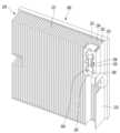
도 18은 본 발명의 제2실시 예에 따른 냉각 장치의 사시도.
도 19는 도 18의 냉각 장치의 평면도.
도 20 및 도 21은 도 18의 냉각 장치의 분해 사시도.
도 22는 본 발명의 제2실시 예에 따른 센서 모듈이 쿨링 싱크에 설치된 모습을 보여주는 정면도.
도 23은 본 발명의 제2실시 예에 따른 센서 모듈이 쿨링 싱크에 설치된 모습을 보여주는 사시도.
도 24는 본 발명의 제2실시 예에 따른 쿨링 싱크의 상면도.
도 25는 본 발명의 제2실시 예에 따른 센서 모듈의 사시도.
도 26은 본 발명의 제2실시 예에 따른 센서 홀더의 종단면도1 is a conceptual diagram showing a first embodiment of a refrigerator including a thermoelectric module.
2 is an exploded perspective view of a thermoelectric element module according to an embodiment of the present invention.
3 is a perspective view of a thermoelectric element module and a defrosting temperature sensor.
FIG. 4 is a plan view of the thermoelectric element module and the defrosting temperature sensor shown in FIG. 3 .
5 is a flowchart showing a control method of a refrigerator proposed in the present invention.
6 is a conceptual diagram for explaining a method of controlling a refrigerator based on whether the temperature of a storage compartment belongs to a first temperature range to a third temperature range.
7 is a flowchart showing defrosting operation control of a refrigerator proposed in the present invention.
8 is a conceptual diagram illustrating the output of the thermoelectric element, the rotational speed of the first fan, and the rotational speed of the second fan according to the lapse of time according to the cooling operation and the natural defrosting operation.
9 is a conceptual diagram showing the output of the thermoelectric element, the rotational speed of the first fan, and the rotational speed of the second fan according to the lapse of time according to the cooling operation and the heat source defrosting operation.
FIG. 10 is a flowchart illustrating operation control corresponding to a load of a refrigerator having a thermoelectric module.
11 is a perspective view of a refrigerator according to a second embodiment of the present invention;
Fig. 12 is a perspective view showing a door opened in Fig. 11;
13 is a plan view of the refrigerator of FIG. 11;
14 is an exploded perspective view of a cabinet according to an embodiment of the present invention;
15 is a view showing a state before assembling a middle plate according to a second embodiment of the present invention;
16 is a view showing a state in which the middle plate according to the second embodiment of the present invention is assembled;
17 is a perspective view of an installation bracket according to a second embodiment of the present invention;
18 is a perspective view of a cooling device according to a second embodiment of the present invention;
Fig. 19 is a plan view of the cooling device of Fig. 18;
20 and 21 are exploded perspective views of the cooling device of FIG. 18;
22 is a front view showing a state in which the sensor module according to the second embodiment of the present invention is installed in a cooling sink;
23 is a perspective view showing a state in which the sensor module according to the second embodiment of the present invention is installed in a cooling sink;
24 is a top view of a cooling sink according to a second embodiment of the present invention;
25 is a perspective view of a sensor module according to a second embodiment of the present invention;
26 is a longitudinal sectional view of a sensor holder according to a second embodiment of the present invention
이하, 본 발명에 관련된 냉장고에 대하여 도면을 참조하여 보다 상세하게 설명한다. 본 명세서에서는 서로 다른 실시예라도 동일, 유사한 구성에 대해서는 동일, 유사한 참조번호를 부여하고, 그 설명은 처음 설명으로 갈음한다. 본 명세서에서 사용되는 단수의 표현은 문맥상 명백하게 다르게 뜻하지 않는 한, 복수의 표현을 포함한다.Hereinafter, a refrigerator related to the present invention will be described in more detail with reference to the drawings. In this specification, the same or similar reference numerals are assigned to the same or similar components even in different embodiments, and the description is replaced with the first description. Singular expressions used herein include plural expressions unless the context clearly dictates otherwise.
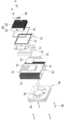
도 1은 열전소자모듈을 구비하는 냉장고의 제1실시 예를 보인 개념도다.1 is a conceptual diagram showing a first embodiment of a refrigerator including a thermoelectric module.
본 발명의 냉장고(100)는 협탁(small side table)과 냉장고(100)의 기능을 동시에 수행하도록 이루어진다. 협탁은 본래 침대 옆이나 주방의 한 켠에 두고 사용하는 작은 탁자를 가리킨다. 협탁은 그 윗면에 스탠드 등을 올려 놓을 수 있도록 이루어지고, 그 내부에는 소품을 수납할 수 있도록 이루어진다. 본 발명의 냉장고(100)는 스탠드 등을 올려 놓을 수 있는 협탁 본래의 기능을 그대로 유지하면서, 그 내부에 식품 등을 저온으로 보관할 수 있도록 이루어진다.The
도 1을 참조하면, 냉장고(100)의 외관은 캐비닛(110)(cabinet)과 도어(130)(door)에 의해 형성된다.Referring to FIG. 1 , the exterior of the
캐비닛(110)은 이너 케이스(111), 아웃 케이스(112) 및 단열재(113)에 의해 형성될 수 있다.The
이너 케이스(111)는 아웃 케이스(112)의 내측에 설치되며, 식품을 저온으로 저장할 수 있는 저장실(120)을 형성한다. 냉장고(100)가 협탁으로 사용되기 위해서는 냉장고(100)의 크기가 제한적일 수 밖에 없으므로, 이너 케이스(111)에 의해 형성되는 저장실(120)의 크기도 약 200L 이하로 제한되어야 한다.The
아웃 케이스(112)는 협탁 형상의 외관을 형성한다. 냉장고(100)의 전면부는 도어(130)가 설치되므로, 아웃 케이스(112)는 냉장고(100)의 전면부를 제외한 나머지 부분의 외관을 형성한다. 아웃 케이스(112)의 윗면은 스탠드 등의 소품을 올려 놓을 수 있도록 평평하게 형성되는 것이 바람직하다.The
단열재(113)는 이너 케이스(111)와 아웃 케이스(112)의 사이에 배치된다. 단열재(113)는 상대적으로 뜨거운 외부로부터 상대적으로 찬 저장실(120)로 열이 전달되는 것을 억제하도록 이루어진다.The
도어(130)는 캐비닛(110)의 전면부에 장착된다. 도어(130)는 캐비닛(110)과 함께 냉장고(100)의 외관을 형성된다. 도어(130)는 슬라이드 이동에 의해 저장실(120)을 개폐하도록 이루어진다. 도어(130)는 냉장고(100)에 두 개(131, 132) 이상 구비될 수 있으며, 도 1에 도시된 바와 같이 각각의 도어(130)는 상하 방향을 따라 배치될 수 있다.The
저장실(120)에는 공간의 효율적이 활용을 위한 드로워(drawer)(140)가 설치될 수 있다. 드로워(140)는 저장실(120) 내에서 식품 보관 영역을 형성하게 되다. 드로워(140)는 도어(130)에 결합되고, 도어(130)의 슬라이드 이동을 따라 저장실(120)로부터 인출 가능하게 형성된다.A
두 개의 드로워(141, 142)가 도어(130)와 마찬가지로 상하 방향을 따라 배치될 수 있다. 하나의 도어(131)(132)마다 하나씩의 드로워(141)(142)가 결합되어, 각각의 도어(131)(132)를 슬라이드 이동시킬 때마다 각 도어(131)(132)에 결합된 드로워(141)(142)가 도어(131)(132)를 따라 저장실(120)로부터 인출될 수 있다.Like the
저장실(120) 뒤에는 기계실(150)이 형성될 수 있다. 기계실(150)을 형성하기 위해 아웃 케이스(112)는 격벽(112a)을 구비할 수 있다. 이 경우 단열재(113)는 격벽(112a)과 이너 케이스(111) 사이에 배치된다. 기계실(150)에는 냉장고(100)의 구동을 위한 각종 전기 설비와 기계 설비 등이 설치될 수 있다.A
캐비닛(110)의 바닥면에는 지지대(160)가 설치될 수 있다. 지지대(160)는 도 1에 도시된 바와 같이 캐비닛(110)을 냉장고(100)가 설치될 바닥으로부터 이격시키도록 형성될 수 있다. 침실 등에 설치되는 냉장고(100)는 주방에 설치되는 냉장고(100)보다 사용자의 접근 빈도가 높다. 따라서 냉장고(100)와 바닥 사이에 누적되는 먼지를 쉽게 청소하기 위해서는 냉장고(100)가 바닥으로부터 이격되는 것이 바람직하다. 지지대(160)는 냉장고(100)가 설치될 바닥으로부터 캐비닛(110)을 이격시키므로, 이 구조를 이용하면 청소를 용이하게 할 수 있다.A
냉장고(100)는 가정 내의 다른 가전 제품과 달리 24시간 내내 작동한다. 따라서 침대 옆에 냉장고(100)가 놓여진다면, 특히 밤 시간에 냉장고(100)에서 소음과 진동이 침대에서 잠을 자는 사람에게 전달되게 되어 수면을 방해하게 된다. 그러므로 냉장고(100)가 침대 옆에 배치되어 협탁과 냉장고(100)의 기능을 동시에 수행하기 위해서는, 냉장고(100)가 충분한 저소음 및 저진동 성능을 가져야 한다.Unlike other home appliances, the
만약 냉장고(100)의 저장실(120)을 냉각하는 용도로 압축기를 포함하는 냉동사이클 장치가 사용된다면, 압축기에서 발생하는 소음과 진동을 원천적으로 차단하기 어렵다. 따라서 저소음 및 저진동 성능 확보를 위해 냉동사이클 장치는 제한적으로만 사용되어야 하며, 본 발명의 냉장고(100)는 열전소자모듈(170)을 이용하여 저장실(120)을 냉각한다.If a refrigeration cycle device including a compressor is used to cool the
열전소자모듈(170)은 저장실(120)의 후벽(111a)에 설치되어 저장실(120)을 냉각하도록 이루어진다. 열전소자모듈(170)은 열전소자를 포함하며, 열전소자는 발명의 배경이 되는 기술 항목에서 설명한 바와 같이 펠티어 효과를 이용하여 냉각과 발열을 구현하는 소자를 가리킨다. 열전소자의 흡열측이 저장실(120)을 향하도록 배치되고 열전소자의 발열측이 냉장고(100)의 외부를 향하도록 배치되면, 열전소자의 작동을 통해 저장실(120)을 냉각할 수 있게 된다.The
제어부(180)는 냉장고(100)의 전반적인 작동을 제어하도록 형성된다. 예를 들어 제어부(180)는 열전소자모듈(170)에 구비되는 열전소자나 팬의 출력을 제어하며, 그 외에 냉장고(100)에 구비되는 각종 구성들의 작동을 제어할 수 있다. 제어부(180)는 인쇄회로기판(PCB)과 마이컴(microcomputer)으로 구성될 수 있다. 제어부(180)는 기계실(150)에 설치될 수 있으나, 반드시 이에 한정되는 것은 아니다.The
제어부(180)가 열전소자모듈(170)를 제어하는 경우에는, 저장실(120)의 온도 사용자에 의해 입력된 설정 온도, 냉장고(100)의 외부 온도 등에 근거하여 열전소자의 출력을 제어할 수 있다. 냉각 운전, 제상 운전, 부하 대응 운전 등은 제어부(180)의 제어에 의해 결정되며, 열전소자의 출력은 제어부(180)에 의해 결정된 운전에 따라 달라진다.When the
상기 저장실(120)의 온도 또는 냉장고의 외부 온도 등은 냉장고에 마련된 센서부(191, 192, 193, 194, 195)에 의해 측정될 수 있다. 센서부(191, 192, 193, 194, 195)는 온도 센서(191, 192, 193), 습도 센서(194), 풍압 센서(195) 등 물성을 측정하는 적어도 하나의 장치로 형성될 수 있다. 예를 들어 온도 센서(191, 192, 193)는 저장실(120), 열전소자모듈(170), 아웃 케이스(112)에 각각 설치될 수 있으며, 각 온도 센서(191, 192, 193)는 자신이 설치된 영역의 온도를 측정하게 된다.The temperature of the
고내 온도 센서(191)는 저장실(120)에 설치되며, 저장실(120)의 온도를 측정하도록 형성된다. 제상 온도 센서(192)는 열전소자모듈(170)에 설치되며, 열전소자모듈(170)의 온도를 측정하도록 형성된다. 외기 온도 센서(193)는 아웃 케이스(112)에 설치되며, 냉장고(100)의 외부 온도를 측정하도록 형성된다.The
습도 센서(194)는 저장실(120)에 설치되며. 저장실(120)의 습도를 측정하도록 형성된다. 풍압 센서(195)는 열전소자모듈(170)에 설치되어 제1 팬(173, 도 2 참조)의 풍압을 측정한다.The
열전소자모듈(170)의 세부 구성에 대하여는 도 2를 참조하여 설명한다.A detailed configuration of the
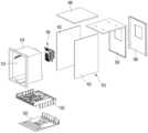
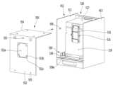
도 2는 열전소자모듈의 분해 사시도다.2 is an exploded perspective view of a thermoelectric element module.
열전소자모듈(170)은 열전소자(171), 쿨링 싱크(172), 제1 팬(173), 히트 싱크(175), 제2 팬(176) 및 단열재(177)를 포함한다. 열전소자모듈(170)은 서로 구분되는 제1 영역과 제2 영역 사이에서 작동하여, 어느 한 영역에서 흡열하고 다른 한 영역에서 방열하도록 이루어진다.The
제1 영역과 제2 영역은 경계에 의해 공간적으로 서로 구분되는 영역들을 가리킨다. 열전소자모듈(170)이 냉장고(도 1의 100)에 적용된다면, 제1 영역은 저장실(도 1의 120)과 냉장고(도 1의 100)의 외부 중 어느 하나에 해당하고, 제2 영역은 다른 하나에 해당한다.The first area and the second area refer to areas spatially separated from each other by a boundary. If the
열전소자(171)는 P형 반도체와 N형 반도체로 PN 접합을 형성하고, 다수의 PN 접합을 직렬로 연결하여 형성된다.The
열전소자(171)는 서로 반대 방향을 향하는 흡열부(171a)와 방열부(171b)를 구비한다. 효과적인 열 전달을 위해서는 흡열부(171a)와 방열부(171b)가 면 접촉 가능한 형상으로 이루어지는 것이 바람직하다. 따라서 흡열부(171a)는 흡열면으로, 방열부(171b)는 방열면으로 명명될 수 있다. 또한 흡열부(171a)와 방열부(171b)를 일반화하여 제1부분과 제2부분으로 명명하거나 제1면과 제2면으로 명명할 수 있다. 이는 설명의 편의를 위한 것일 뿐, 발명의 범위를 제한하는 것은 아니다.The
쿨링 싱크(172)는 열전소자(171)의 흡열부(171a)와 접촉하도록 배치된다. 쿨링 싱크(172)는 제1 영역과 열 교환 하도록 이루어진다. 제1 영역은 냉장고(도 1의 100)의 저장실(도 1의 120)에 해당하며, 쿨링 싱크(172)의 열 교환 대상은 저장실(도 1의 120) 내부의 공기다.The
제1 팬(173)은 쿨링 싱크(172)를 마주보도록 설치되며, 쿨링 싱크(172)의 열 교환을 촉진하도록 바람을 일으킨다. 열 교환은 자연 현상이기 때문에 제1 팬(173)이 없더라도 쿨링 싱크(172)는 저장실(도 1의 120)의 공기와 열 교환 가능하다. 그러나 열전소자모듈(170)이 제1 팬(173)을 포함함에 따라 쿨링 싱크(172)의 열 교환이 더욱 촉진될 수 있다.The
제1 팬(173)은 커버(174)에 의해 감싸일 수 있다. 커버(174)는 제1 팬(173)을 감싸는 부분(174a) 외에 다른 부분을 포함할 수 있다. 제1 팬(173)을 감싸는 부분(174a)에는 저장실(도 1의 120) 내부의 공기가 상기 커버(174)를 통과할 수 있도록 다수의 홀(174b)이 형성될 수 있다.The
또한 커버(174)는 저장실(도 1의 120)의 후벽(도 1의 111a)에 고정될 수 있는 구조를 가질 수 있다. 일 예로 도 2에는 커버(174)가 제1 팬(173)을 감싸는 부분(174a)의 양측에서 연장되는 부분(174c)을 구비하고, 상기 연장되는 부분(174c)에 나사 삽입 가능한 나사 체결공(174e)이 형성되는 구조가 도시되어 있다. 아울러 제1 팬(173)을 감싸는 부분에 나사(179c)가 삽입되어 커버(174)를 후벽(도 1의 111a)에 추가 고정시킬 수 있다. 상기 제1 팬(173)을 감싸는 부분(174a)과 상기 연장되는 부분(174c)에 공기가 통과할 수 있는 모두 홀(174b)(174d)이 형성될 수 있다.Also, the
히트 싱크(175)는 열전소자(171)의 방열부(171b)와 접촉하도록 배치된다. 히트 싱크(175)는 제2 영역과 열 교환 하도록 이루어진다. 제2 영역은 냉장고(도 1의 100)의 외부 공간에 해당하며, 히트 싱크(175)의 열 교환 대상은 냉장고(도 1의 100) 외부의 공기다.The
제2 팬(176)은 히트 싱크(175)를 마주보도록 설치되며, 히트 싱크(175)의 열 교환을 촉진하도록 바람을 일으킨다. 제2 팬(176)이 히트 싱크(175)의 열 교환을 촉진하는 것은 제1 팬(173)이 쿨링 싱크(172)의 열 교환을 촉진하는 것과 동일하다.The
제2 팬(176)은 선택적으로 슈라우드(176c)를 구비할 수 있다. 슈라우드(176c)는 바람을 가이드 하도록 이루어진다. 예를 들어 슈라우드(176c)는 도 2에 도시된 바와 같이 베인들(176b)로부터 이격된 위치에서 베인들(176b)을 감싸도록 이루어질 수 있다. 추가로 슈라우드(176c)에는 제2 팬(176)의 고정을 위한 나사 체결공(176d)이 형성될 수 있다.The
쿨링 싱크(172)와 제1 팬(173)은 열전소자모듈(170)의 흡열측에 해당한다. 그리고 히트 싱크(175)와 제2 팬(176)은 열전소자모듈(170)의 발열측에 해당한다.The
쿨링 싱크(172)와 히트 싱크(175) 중 적어도 하나는 각각 베이스(172a)(175a)와 핀들(fins)(172b)(175b)을 포함한다. 다만, 이하에서는 쿨링 싱크(172)와 히트 싱크(175)가 모두 베이스(172a)(175a)와 핀들(172b)(175b)을 포함하는 것을 전제로 설명한다.At least one of the
베이스(172a)(175a)는 열전소자(171)와 면 접촉하도록 이루어진다. 쿨링 싱크(172)의 베이스(172a)는 열전소자(171)의 흡열부(171a)와 면 접촉하고, 히트 싱크(175)의 베이스(175a)는 열전소자(171)의 방열부(171b)와 면 접촉한다.The
열 전달 면적이 커질수록 열전도율이 증가하므로, 베이스(172a)(175a)와 열전소자(171)는 서로 면 접촉하는 것이 이상적이다. 또한 베이스(172a)(175a)와 열전소자(171) 사이에 미세한 간극을 채워 열전도율을 증가시키기 위해 열전도체(thermal grease 또는 thermal compound)가 이용될 수 있다.Since the thermal conductivity increases as the heat transfer area increases, it is ideal that the
핀들(172b)(175b)은 제1 영역의 공기 또는 제2 영역의 공기와 열 교환 하도록 베이스(172a)(175a)로부터 돌출된다. 제1 영역은 저장실(도 1의 120)에 해당하고, 제2 영역은 냉장고(도 1의 100)의 외부에 해당하므로, 쿨링 싱크(172)의 핀들(172b)은 저장실(도 1의 120)의 공기와 열 교환 하도록 이루어지고, 히트 싱크(175)의 핀들(175b)은 냉장고(도 1의 100)의 외부 공기와 열 교환 하도록 이루어진다.The
핀들(172b)(175b)은 서로 이격되게 배치된다. 핀들(172b)(175b)이 서로 이격됨에 따라 열 교환 면적이 증가할 수 있기 때문이다. 핀들(172b)(175b)이 만약 서로 붙어 있다면 핀들(172b)(175b) 사이에 열 교환 면적이 존재하지 않을 것이나, 핀들(172b)(175b)이 서로 이격되어 있으므로 핀들(172b)(175b) 사이사이에도 열 교환 면적이 존재할 수 있다. 열 전달 면적이 커질수록 열전도율이 증가하므로, 히트 싱크의 열 전달 성능을 향상시키기 위해서는 제1 영역과 제2 영역에 노출되는 핀들의 면적이 커져야 한다.The
또한, 흡열측에 해당하는 쿨링 싱크(172)의 충분한 냉각 효과를 구현하기 위해서는 발열측에 해당하는 히트 싱크(175)의 열전도율이 쿨링 싱크(172)에 비해 커야 한다. 열전소자(171)의 방열부(171b)에서 더욱 신속하게 방열이 이루어져야 흡열부(171a)에서 충분한 흡열이 이루어지기 때문이다. 이것은 열전소자(171)가 단순한 열전도체가 아니라 전압을 인가함에 따라 일측에서 흡열이 이루어지고, 타측에서 방열이 이루어지는 소자라는 것에서 기인한다. 따라서 열전소자(171)의 방열부(171b)에서 더욱 강한 방열이 이루어져야 흡열부(171a)에서 충분한 냉각이 구현될 수 있다.In addition, in order to realize a sufficient cooling effect of the
이러한 점을 고려할 때 쿨링 싱크(172)에서 흡열이 이루어지고 히트 싱크(175)에서 방열이 이루어진다면, 쿨링 싱크(172)의 열 교환 면적보다 히트 싱크(175)의 열 교환 면적이 커야 한다. 쿨링 싱크(172)의 모든 열 교환 면적이 모두 열 교환에 이용된다고 가정하면, 히트 싱크(175)의 열 교환 면적이 쿨링 싱크(172)의 열 교환 면적보다 3배 이상인 것이 바람직하다.Considering this point, if heat is absorbed by the
이것은 제1 팬(173)과 제2 팬(176)에도 동일하게 적용되는 원리이다. 흡열 측에 충분한 냉각 효과를 구현하기 위해서 제2 팬(176)에 의해 형성되는 풍량과 풍속은 제1 팬(173)에 의해 형성되는 풍량과 풍속보다 큰 것이 바람직하다.This principle is equally applied to the
히트 싱크(175)는 쿨링 싱크(172)에 비해 더 큰 열 교환 면적을 필요로 하기 때문에, 베이스(175a)와 핀들(175b)의 면적이 쿨링 싱크(172)의 그것들(172a)(172b)보다 더욱 크다. 나아가 히트 싱크(175)의 베이스(175a)로 전달된 열을 핀들에 신속하게 분배하기 위해 히트 싱크(175)는 히트 파이프(175c)를 구비할 수 있다.Since the
히트 파이프(175c)는 내부에 열 전달 유체를 수용하도록 이루어지며, 히트 파이프(175c)의 일단은 베이스(175a)를 관통하고 타단은 핀들(175b)을 관통한다. 히트 파이프(175c)는 내부에 수용된 열 전달 유체의 증발을 통해 열을 베이스(175a)에서 핀들(175b)로 전달하는 장치다. 히트 파이프(175c)가 없다면, 베이스(175a)의 인접한 핀들(175b)에서만 열 교환이 집중될 것이다. 베이스(175a)로부터 멀리 존재하는 핀들(175b)에는 열이 충분히 분배되지 않기 때문이다.The
그러나 히트 파이프(175c)가 존재함에 따라 히트 싱크(175)의 모든 핀들(175b)에서 열 교환이 이루어질 수 있다. 베이스(175a)의 열이 베이스(175a)로부터 상대적으로 멀리 배치된 핀들(175b)에도 골고루 분배될 수 있기 때문이다.However, since the
히트 싱크(175)의 베이스(175a)는 히트 파이프(175c)를 내장하기 위해 두 겹(두 레이어)(175a1, 175a2)으로 형성될 수 있다. 베이스(175a)의 제1 레이어(175a1)는 히트 파이프(175c)의 일 측을 감싸고 제2 레이어(175a2)는 히트 파이프(175c)의 타 측을 감싸도록 이루어지며, 두 겹(175a1, 175a2)은 서로 마주보도록 배치될 수 있다.The
제1 레이어(175a1)는 열전소자(171)의 방열부(171b)와 접촉하도록 배치되며, 열전소자(171)와 동일 내지 유사한 크기를 가질 수 있다. 제2 레이어(175a2)는 핀들(175b)과 연결되며, 핀들(175b)은 제2 레이어(175a2)로부터 돌출된다. 제2 레이어(175a2)는 제1 레이어(175a1)보다 큰 크기를 가질 수 있다. 그리고 히트 파이프(175c)의 일단은 제1 레이어(175a1)와 제2 레이어(175a2) 사이에 배치된다.The first layer 175a1 is disposed to contact the
단열재(177)는 쿨링 싱크(172)와 히트 싱크(175) 사이에 설치된다. 단열재(177)는 열전소자(171)의 테두리를 감싸도록 형성된다. 예를 들어 도 2에 도시된 바와 같이 단열재(177)에는 구멍(177a)이 형성되고, 구멍(177a)에 열전소자(171)가 배치될 수 있다.An
앞서 설명한 바와 같이 열전소자모듈(170)은 열전소자(171)의 일측과 타측에서 이루어지는 흡열과 방열을 통해 저장실(도 1의 120)의 냉각을 구현하는 소자이지 단순한 열전도체가 아니다. 따라서 쿨링 싱크(172)의 열이 히트 싱크(175)로 직접 전달되는 것은 바람직하지 못하다. 직접적인 열 전달로 인해 쿨링 싱크(172)와 히트 싱크(175) 간의 온도차가 줄어들면, 열전소자(171)의 성능을 저하시키는 원인이 되기 때문이다. 이러한 현상을 방지하기 위해 단열재(177)는 쿨링 싱크(172)와 히트 싱크(175) 간의 직접적인 열 전달을 차단하도록 이루어진다.As described above, the
체결 플레이트(178)는 쿨링 싱크(172)와 단열재(177) 사이에 배치되거나 히트 싱크(175)와 단열재(177) 사이에 배치된다. 체결 플레이트(178)는 쿨링 싱크(172)와 히트 싱크(175)의 고정을 위한 것으로, 쿨링 싱크(172)와 히트 싱크(175)는 나사에 의해 상기 체결 플레이트(178)에 나사 결합될 수 있다.The
체결 플레이트(178)는 단열재(177)와 함께 열전소자(171)의 테두리를 감싸도록 형성될 수 있다. 체결 플레이트(178)는 단열재(177)와 마찬가지로 열전소자(171)에 대응되는 구멍(178a)을 구비하고, 상기 구멍(178a)에 열전소자(171)가 배치될 수 있다. 다만, 체결 플레이트(178)는 열전소자모듈(170)의 필수적인 구성은 아니고, 쿨링 싱크(172)와 히트 싱크(175)를 고정할 수 있는 다른 구성으로 대체 가능하다.The
체결 플레이트(178)에는 쿨링 싱크(172)와 히트 싱크(175)의 고정을 위한 다수의 나사 체결공(178b)(178c)이 형성될 수 있다. 쿨링 싱크(172)와 단열재(177)에는 체결 플레이트(178)에 대응되는 나사 체결공(172c)(177b)이 형성되며, 나사(179a)가 상기 세 나사 체결공(172c, 177b, 178b)에 순차적으로 삽입되어 쿨링 싱크(172)를 체결 플레이트(178)에 고정시킬 수 있다. 히트 싱크(175)에도 체결 플레이트(178)에 대응되는 나사 체결공(175d)이 형성되며, 나사(179b)가 상기 두 나사 체결공(178c, 175d)에 순차적으로 삽입되어 히트 싱크(175)를 체결 플레이트(178)에 고정시킬 수 있다.A plurality of screw fastening holes 178b and 178c for fixing the
체결 플레이트(178)에는 히트 파이프(175c)의 일측을 수용하도록 이루어지는 리세스부(178d)가 형성될 수 있다. 리세스부(178d)는 히트 파이프(175c)에 대응되게 형성되며 부분적으로 감싸도록 이루어질 수 있다. 히트 싱크(175)가 히트 파이프(175c)를 구비하더라도, 체결 플레이트(178)가 리세스부(178d)를 구비하므로, 히트 싱크(175)가 체결 플레이트(178)에 밀착될 수 있으며, 열전소자모듈(170)의 전체 두께를 더 얇게 만들 수 있다.A recessed
앞서 설명된 제1 팬(173)과 제2 팬(176) 중 적어도 하나는 허브(173a)(176a)와 베인들(173b)(176b)을 구비한다. 허브(173a)(176a)는 회전 중심축(미도시)에 결합된다. 베인들(vanes)(173b)(176b)은 허브(173a)(176a)의 둘레에 방사형으로 설치된다.At least one of the above-described
축류팬(173)(176)은 원심팬으로부터 구분된다. 축류팬(173)(176)은 회전축 방향으로 바람을 일으키도록 형성되며, 축류팬(173)(176)의 회전축 방향으로 공기가 들어와서 회전축 방향으로 나간다. 이에 반해 원심팬은 원심 방향(또는 원주 방향)으로 바람을 일으키도록 형성되며, 원심팬의 회전축 방향으로 공기가 들어와 원심 방향으로 나간다.
제상 온도 센서(192)는 열전소자모듈에 장착되며, 열전소자모듈(170)의 온도를 측정하도록 형성된다. 도 2를 참조하면 제상 온도 센서(192)는 쿨링 싱크(172)에 결합된다. 제상 온도 센서(192)의 구조에 대하여는 도 3과 도 4를 참조하여 설명한다.The
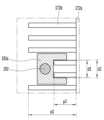
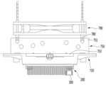
도 3은 열전소자모듈과 제상 온도 센서(192)의 사시도다. 도 4는 도 3에 도시된 열전소자모듈(170)과 제상 온도 센서(192)의 평면도다.3 is a perspective view of the thermoelectric element module and the
제상 온도 센서(192)는 쿨링 싱크(172)의 핀(172b)에 결합된다. 쿨링 싱크(172)의 핀(172b)들은 베이스(172a)로부터 돌출되어 있는데, 그 중 일부는 다른 핀에 비해 짧은 돌출 길이(p2)를 갖는다.The
제상 온도 센서(192)는 센서 홀더(192a)에 의해 감싸이며, 센서 홀더(192a)는 다른 핀에 비해 짧은 돌출 길이를 갖는 핀에 끼워질 수 있는 형상을 갖는다. 도 3에는 센서 홀더(192a)의 양측 다리가 두 핀에 끼워진 구조가 도시되어 있다. 두 핀의 외측면 간의 거리(d1)보다 센서 홀더(192a)의 양측 다리 사이의 거리(d2)가 미소하게 작다면, 센서 홀더(192a)가 두 핀에 끼워질 수 있다.The
제상 온도 센서(192)의 위치는 제상 운전 시 상기 쿨링 싱크(172)에서 온도 상승이 가장 오래 걸리는 곳으로 선정된다. 그래야 제상 운전의 신뢰성을 제고할 수 있기 때문이다. 제상 온도 센서(192)의 위치는 센서 홀더(192a)의 위치에 의해 결정된다.The location of the
쿨링 싱크(172)에서 중심에 배치되는 핀은 베이스(172a)와 가장 가깝기 때문에 제상 운전 시 온도 상승이 신속하게 이루어진다. 반면 쿨링 싱크(172)에서 바깥쪽에 배치되는 핀은 베이스(172a)로부터 멀리 떨어져 있기 때문에 제상 운전 시 온도 상승이 느리다.Since the fin disposed at the center of the
다만, 최외곽의 핀은 열전소자모듈(170)의 영향뿐만 아니라 상기 열전소자모듈(170) 외측의 공기에 의한 영향도 받게 된다. 따라서 최외곽의 핀보다는 그 바로 안쪽의 핀에 센서 홀더(192a)가 결합되는 것이 바람직하다. 또한 센서 홀더(192a)의 상하 위치는 핀의 가장 상측 또는 하측이 바람직하며, 도 3에서는 핀의 가장 상측에 센서 홀더(192a)가 결합된 것으로 도시되어 있다.However, the outermost pin is affected not only by the
핀의 돌출 길이가 일정하더라도 센서 홀더(192a)가 핀에 끼워질 수는 있다. 그러나 핀의 길이가 일정하게 되면, 제상 온도 센서(192)가 베이스(172a)로부터 너무 멀리 이격되기 때문에 정확한 온도 측정이 어려워진다. 따라서 센서 홀더(192a)가 결합되는 핀의 돌출 길이(p2)는 타 핀의 돌출 길이(p1)보다 짧은 길이를 갖는 것이 바람직하다.Even if the protruding length of the pin is constant, the
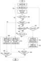
도 5는 본 발명에서 제안하는 냉장고의 제어 방법을 보인 흐름도다.5 is a flowchart showing a control method of a refrigerator proposed in the present invention.
(S100) 먼저, 열전소자모듈은 전원 최초 투입 등을 이유로 전원을 공급받으면 냉각 운전을 시작하게 된다. 자연 제상 등을 이유로 열전소자모듈의 전원이 차단될 수도 있으므로, 자연 제상이 종료된 후에 열전소자모듈에 다시 전원이 투입되면, 열전소자모듈이 냉각 운전을 재개하게 된다.(S100) First, the thermoelectric element module starts a cooling operation when power is supplied for the reason of initial power-on or the like. Since power to the thermoelectric module may be cut off for reasons such as natural defrosting, when power is supplied to the thermoelectric module again after the natural defrost is finished, the thermoelectric module resumes the cooling operation.
(S200) 이어서, 열전소자모듈의 구동 시간을 적산하게 된다. 적산이란 열전소자모듈의 구동 시간을 누적적으로 카운팅하는 것을 의미한다. 열전소자모듈의 구동 시간 적산은 냉장고의 제어 과정 동안 계속되며, 제상 운전을 투입하는 근거가 된다.(S200) Then, the driving time of the thermoelectric module is accumulated. Integration means accumulatively counting the driving time of the thermoelectric module. The integration of the driving time of the thermoelectric module continues during the control process of the refrigerator and serves as a basis for inputting the defrosting operation.
(S300) 다음으로는, 냉장고의 외부 온도, 저장실의 온도, 열전소자모듈의 온도를 측정하게 된다. 이 단계에서 측정되는 온도들은 사용자에 의해 입력된 설정 온도와 함께 제어부에서 열전소자의 출력이나 팬의 출력을 제어하는 것에 이용될 수 있다.(S300) Next, the external temperature of the refrigerator, the temperature of the storage compartment, and the temperature of the thermoelectric module are measured. The temperatures measured in this step, together with the set temperature input by the user, may be used by the controller to control the output of the thermoelectric element or the output of the fan.
(S400) 부하 대응 운전의 필요성을 판단한다. 부하 대응 운전이란 냉장고의 저장실에 뜨거운 음식물 등이 투입됨에 따라 저장실을 신속하게 냉각하는 운전을 가리킨다. 부하 대응 운전의 필요성을 판단하는 근거에 대하여는 후술한다. 부하 대응 운전이 필요하다고 판단되면 부하 대응 운전을 가동하여 열전소자가 미리 설정된 출력으로 운전되며, 팬이 미리 설정된 회전 속도로 회전된다. 부하 대응 운전이 필요하지 않다고 판단되면 다음 단계로 진행된다.(S400) It is determined whether load response operation is necessary. The load response operation refers to an operation of rapidly cooling the storage compartment of the refrigerator as hot food or the like is put into the storage compartment. A basis for determining the need for load response operation will be described later. If it is determined that the load response operation is necessary, the load response operation is operated so that the thermoelectric element is operated with a preset output and the fan is rotated at a preset rotation speed. If it is determined that load response operation is not necessary, the next step is performed.
(S500) 제상 운전의 필요성을 판단한다. 제상 운전이란 서리가 열전소자모듈에 착상되는 것을 방지하거나 착상된 서리를 제거하는 운전을 가리킨다. 마찬가지로 제상 운전의 필요성을 판단하는 근거에 대하여는 후술한다. 제상 운전이 필요하다고 판단되면 제상 운전을 가동하여 열전소자가 미리 설정된 출력으로 운전되며, 팬이 미리 설정된 회전 속도로 회전된다. 다만, 자연 제상의 경우에는 열전소자에 공급되는 전원이 차단될 수 있다. 제상 운전이 필요하지 않다고 판단되면 다음 단계로 진행된다.(S500) The necessity of defrosting operation is determined. The defrosting operation refers to an operation to prevent frost from being implanted on the thermoelectric module or to remove the frost. Similarly, the basis for determining the necessity of defrosting operation will be described later. When it is determined that the defrosting operation is necessary, the defrosting operation is operated, the thermoelectric element is operated with a preset output, and the fan is rotated at a preset rotation speed. However, in the case of natural defrosting, power supplied to the thermoelectric element may be cut off. If it is determined that the defrost operation is not necessary, the next step is performed.
(S600) 부하 대응 운전과 제상 운전은 냉각 운전에 선행하기 때문에 부하 대응 운전과 제상 운전이 필요하지 않다고 판단된 경우에 냉각 운전이 투입된다. 냉각 운전은 저장실의 온도와 사용자에 의해 입력된 온도를 근거로 제어된다. 제어의 결과는 열전소자의 출력과 팬의 출력으로 나타난다.(S600) Since the load response operation and the defrost operation precede the cooling operation, the cooling operation is input when it is determined that the load response operation and the defrost operation are not necessary. The cooling operation is controlled based on the temperature of the storage compartment and the temperature input by the user. The result of the control appears as the output of the thermoelectric element and the output of the fan.
본 발명에서는 열전소자의 출력이 저장실의 온도, 사용자에 의해 입력된 설정 온도, 및 냉장고의 외부 온도에 근거하여 결정된다. 또한 본 발명에서는 팬의 회전 속도가 저장실의 온도에 근거하여 결정된다. 여기서 팬이란 열전소자모듈의 제1 팬과 제2 팬 중 적어도 하나를 의미한다.In the present invention, the output of the thermoelectric element is determined based on the temperature of the storage compartment, the set temperature input by the user, and the external temperature of the refrigerator. Also, in the present invention, the rotational speed of the fan is determined based on the temperature of the storage compartment. Here, the fan means at least one of a first fan and a second fan of the thermoelectric module.
예컨대 도 5의 흐름도에서 저장실의 온도가 제3 온도 구간에 해당하면, 열전소자는 제3 출력으로 운전되고, 팬은 제3 회전 속도로 회전된다. 저장실의 온도가 제2 온도 구간에 해당하면, 열전소자는 제2 출력으로 운전되고, 팬은 제2 회전 속도로 회전된다. 저장실의 온도가 제1 온도 구간에 해당하면, 열전소자는 제1 출력으로 운전되고, 팬은 제1 회전 속도로 회전된다.For example, in the flowchart of FIG. 5 , when the temperature of the storage compartment corresponds to the third temperature range, the thermoelectric element operates at the third output and the fan rotates at the third rotation speed. When the temperature of the storage compartment corresponds to the second temperature range, the thermoelectric element is operated with the second output and the fan is rotated at the second rotational speed. When the temperature of the storage compartment corresponds to the first temperature range, the thermoelectric element is operated with a first output and the fan is rotated at a first rotational speed.
열전 소자의 출력과 팬의 회전 속도는 상대적인 개념으로, 그 세부 구성에 대하여는 후술한다.The output of the thermoelectric element and the rotational speed of the fan are relative concepts, and detailed configurations thereof will be described later.
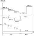
이하에서는 도 6, 그리고 표 1을 참조하여 각 온도 구간 별 열전소자와 팬의 제어에 대하여 설명한다. 다만, 도면과 표의 수치들은 본 발명의 개념을 설명하기 위한 일 예에 해당하는 것일 뿐, 본 발명에서 제안하는 제어 방법에 반드시 필요한 절대적인 값을 의미하는 것은 아니다.Hereinafter, control of the thermoelectric element and the fan for each temperature section will be described with reference to FIG. 6 and Table 1. However, the numerical values in the drawings and tables are merely examples for explaining the concept of the present invention, and do not mean absolute values necessary for the control method proposed in the present invention.
도 6은 저장실의 온도가 제1 온도 구간 내지 제3 온도 구간 중 어느 구간에 속하는지에 근거한 냉장고의 제어 방법을 설명하기 위한 개념도다.6 is a conceptual diagram for explaining a method of controlling a refrigerator based on whether the temperature of a storage compartment belongs to a first temperature range to a third temperature range.
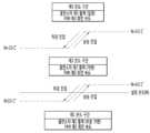
저장실의 온도는 제1 온도 구간, 제2 온도 구간, 제3 온도 구간으로 구분된다. 여기서 제1 온도 구간은 사용자에 의해 입력된 설정 온도를 포함하는 구간이다. 제2 온도 구간은 제1 온도 구간보다 높은 온도의 구간이다. 제3 온도 구간은 제2 온도 구간보다 높은 온도의 구간이다. 따라서 제1 온도 구간으로부터 제3 온도 구간으로 갈수록 온도가 순차적으로 증가한다.The temperature of the storage compartment is divided into a first temperature range, a second temperature range, and a third temperature range. Here, the first temperature range is a range including a set temperature input by the user. The second temperature range is a range having a higher temperature than the first temperature range. The third temperature range is a higher temperature range than the second temperature range. Accordingly, the temperature sequentially increases from the first temperature range to the third temperature range.
제1 온도 구간은 사용자에 의해 입력된 설정 온도를 포함하기 때문에, 저장실의 온도가 제1 온도 구간에 있다면 열전소자모듈의 작동으로 인해 저장실의 온도가 이미 설정 온도까지 낮아졌다는 것을 의미한다. 따라서 제1 온도 구간은 설정 온도를 만족하는 구간이다.Since the first temperature range includes the set temperature input by the user, if the temperature of the storage compartment is in the first temperature range, it means that the temperature of the storage compartment has already been lowered to the set temperature due to the operation of the thermoelectric module. Therefore, the first temperature range is a range that satisfies the set temperature.
제2 온도 구간과 제3 온도 구간은 사용자에 의해 입력된 설정 온도보다 높은 온도 구간이기 때문에 설정 온도를 만족하지 못하는 불만족 구간이다. 따라서 제2 온도 구간과 제3 온도 구간에서는 열전소자모듈이 작동하여 저장실의 온도를 설정 온도까지 낮춰야 한다. 다만, 제3 온도 구간은 제2 온도 구간보다 더 높은 온도에 해당하므로, 더욱 강력한 냉각을 요구하는 구간이다. 제2 온도 구간과 제3 온도 구간을 서로 구분하기 위해 제2 온도 구간은 불만족 구간, 제3 온도 구간은 상한 구간으로 명명될 수 있다.The second temperature range and the third temperature range are unsatisfactory intervals that do not satisfy the set temperature because they are temperature ranges higher than the set temperature input by the user. Therefore, in the second temperature range and the third temperature range, the thermoelectric module must operate to lower the temperature of the storage compartment to a set temperature. However, since the third temperature range corresponds to a higher temperature than the second temperature range, more powerful cooling is required. In order to distinguish the second temperature range and the third temperature range from each other, the second temperature range may be referred to as an unsatisfactory range and the third temperature range may be referred to as an upper limit range.
각 온도 구간의 경계는 저장실의 온도가 상승 진입하는지 하강 진입하는지에 따라 달라진다. 예를 들어 도 6를 기준으로 저장실의 온도가 상승하여 제1 온도 구간에서 제2 온도 구간으로 상승 진입하는 상승 진입 온도는 N+0.5℃다. 반대로 저장실의 온도가 하강하여 제2 온도 구간에서 제1 온도 구간으로 진입하는 하강 진입 온도는 N-0.5℃다. 따라서 상승 진입 온도는 하강 진입 온도보다 높다.The boundary of each temperature section varies depending on whether the temperature of the storage compartment rises or falls. For example, based on FIG. 6 , the temperature of the storage compartment rises and the rising entry temperature from the first temperature section to the second temperature section is N+0.5°C. Conversely, when the temperature of the storage compartment decreases and the second temperature range enters the first temperature range, the descending entry temperature is N-0.5°C. Therefore, the rising entry temperature is higher than the falling entry temperature.
저장실의 온도가 제1 온도 구간에서 제2 온도 구간으로 진입하는 상승 진입 온도(N+0.5℃)는 사용자에 의해 입력된 설정 온도(N)보다 높을 수 있다. 반대로 저장실의 온도가 제2 온도 구간에서 제1 온도 구간으로 진입하는 하강 진입 온도(N-0.5℃)는 사용자에 의해 입력된 설정 온도(N)보다 낮을 수 있다.The rising entry temperature (N+0.5°C) at which the temperature of the storage compartment enters the second temperature range from the first temperature range may be higher than the set temperature (N) input by the user. Conversely, a descending entry temperature (N-0.5° C.) at which the temperature of the storage compartment enters the first temperature range from the second temperature range may be lower than the set temperature (N) input by the user.
마찬가지로 도 6를 기준으로 저장실의 온도가 상승하여 제2 온도 구간에서 제3 온도 구간으로 상승 진입하는 상승 진입 온도는 N+3.5℃다. 반대로 저장실의 온도가 하강하여 제3 온도 구간에서 제2 온도 구간으로 진입하는 하강 진입 온도는 N+2.0℃다. 따라서 상승 진입 온도는 하강 진입 온도보다 높다.Similarly, based on FIG. 6 , the temperature of the storage compartment rises and the rising entry temperature from the second temperature range to the third temperature range is N+3.5°C. Conversely, the temperature of the storage compartment decreases and the entry temperature for entering the second temperature range from the third temperature range is N+2.0°C. Therefore, the rising entry temperature is higher than the falling entry temperature.
만일 상승 진입 온도가 하강 진입 온도가 서로 같다면, 저장실이 충분히 냉각되지 않은 채 열전소자나 팬의 제어가 다시 변경된다. 예를 들어 제2 온도 구간에서 제1 온도 구간으로 진입하자 마자 저장실의 설정 온도가 만족되어 열전소자와 팬이 정지하게 된다면, 저장실의 온도는 곧바로 다시 제2 온도 구간으로 진입하게 된다. 이러한 현상을 방지하고 저장실의 온도를 제1 온도 구간에 충분히 머무르게 하게 위해서는 반드시 하강 진입 온도가 상승 진입 온도보다 낮아야 한다.If the rising entry temperature and the falling entry temperature are equal to each other, the control of the thermoelectric element or fan is changed again without sufficiently cooling the storage compartment. For example, as soon as the second temperature range enters the first temperature range, if the set temperature of the storage compartment is satisfied and the thermoelectric element and the fan are stopped, the temperature of the storage compartment immediately enters the second temperature range again. In order to prevent this phenomenon and make the temperature of the storage compartment sufficiently stay in the first temperature range, the falling entry temperature must be lower than the rising entry temperature.
여기서는 먼저 임의의 설정 온도에서 열전소자의 출력과 팬의 회전 속도에 대하여 설명한다. 이어서 설정 온도에 따른 제어의 변화에 대하여 설명한다.Here, the output of the thermoelectric element and the rotational speed of the fan at an arbitrary set temperature will be described first. Next, a change in control according to the set temperature will be described.
임의의 설정 온도(N1)에서 열전소자의 출력은 표 1에 나타내었다. 표 1에서 Hot/Cool 항목에서는 쿨링 싱크와 접촉하는 열전소자의 일 면이 흡열 작용을 하고 있는 흡열면에 해당하면 Cool로 표시하고, 반대로 상기 일 면이 방열 작용을 하고 있는 방열면에 해당하면 Hot로 표시한다. 또한 RT는 냉장고의 외부 온도(room temperature)를 가리킨다.The output of the thermoelectric element at a certain set temperature (N1) is shown in Table 1. In Table 1, in the Hot/Cool category, if one side of the thermoelectric element in contact with the cooling sink corresponds to the heat absorbing side that is absorbing heat, it is indicated as Cool, and conversely, if the one side corresponds to the radiating side that is radiating heat, Hot is indicated. indicated by Also, RT refers to the outside temperature of the refrigerator (room temperature).

열전소자의 출력은 (a) 저장실의 온도가 제1 온도 구간, 제2 온도 구간 및 제3 온도 구간 중 어느 구간에 속하는지에 근거하여 결정된다.The output of the thermoelectric element is (a) determined based on which of the first temperature range, the second temperature range, and the third temperature range the temperature of the storage compartment belongs to.
열전소자에 인가되는 전압이 높을수록 열전소자의 출력이 커지므로, 열전소자의 출력은 열전소자에 인가되는 전압으로부터 알 수 있다. 열전소자의 출력이 커지면 열전소자는 더욱 강한 냉각을 구현할 수 있다.Since the output of the thermoelectric element increases as the voltage applied to the thermoelectric element increases, the output of the thermoelectric element can be known from the voltage applied to the thermoelectric element. As the output of the thermoelectric element increases, the thermoelectric element can realize stronger cooling.
한편, 팬의 회전속도는 (a) 저장실의 온도가 상기 제1 온도 구간, 상기 제2 온도 구간 및 상기 제3 온도 구간 중 어느 구간에 속하는지에 근거하여 결정된다. 여기서 팬이란 열전소자모듈의 제1 팬 및/또는 제2 팬을 가리킨다.On the other hand, the rotational speed of the fan is determined based on (a) to which of the first temperature range, the second temperature range, and the third temperature range the temperature of the storage compartment belongs. Here, the fan refers to the first fan and/or the second fan of the thermoelectric module.
팬의 회전 속도는 단위 시간당 팬의 회전수(RPM)로부터 알 수 있다. 팬의 RPM이 크다는 것은 팬이 더 빠르게 회전한다는 것을 의미한다. 팬이 더욱 높은 전압이 인가되면 팬의 회전수가 증가한다. 팬이 더욱 빠르게 회전하면 쿨링 싱크 및/또는 히트 싱크의 열교환을 더욱 촉진하게 되어 더욱 강한 냉각을 구현할 수 있다.The rotational speed of the fan can be known from the rotational speed (RPM) of the fan per unit time. A higher fan RPM means that the fan spins faster. When a higher voltage is applied to the fan, the rotational speed of the fan increases. When the fan rotates faster, heat exchange between the cooling sink and/or the heat sink is further promoted, so that stronger cooling may be realized.
도 6을 참조할 때 저장실의 온도가 제3 온도 구간에 해당하면, 열전소자는 제3 출력으로 운전된다. 표 1에서 제3 출력은 외부 온도에 관계없이 +22V다. 따라서 제3 출력은 외부 온도에 관계없이 일정한 값이다.Referring to FIG. 6 , when the temperature of the storage compartment corresponds to the third temperature range, the thermoelectric element is operated with the third output. In Table 1, the third output is +22V regardless of the outside temperature. Therefore, the third output is a constant value regardless of the external temperature.
제3 출력(+22V)은 제1 온도 구간의 제1 출력(표 1에서의 0V, +12V, +16V)을 초과하는 값이다. 그리고 제3 출력은 제2 온도 구간의 제2 출력(표 1에서의 +12V, +14V, +16V, +22V) 이상의 값이다.The third output (+22V) is a value exceeding the first output (0V, +12V, +16V in Table 1) of the first temperature range. And the third output is a value greater than or equal to the second output (+12V, +14V, +16V, +22V in Table 1) of the second temperature range.
제3 출력은 열전소자의 최대 출력에 해당할 수 있다. 이 경우 제3 온도 구간에서 열전소자의 출력은 상기 최대 출력으로 일정하게 유지된다.The third output may correspond to the maximum output of the thermoelectric element. In this case, the output of the thermoelectric element is constantly maintained at the maximum output in the third temperature range.
또한, 저장실의 온도가 제3 온도 구간에 해당하면, 팬이 제3 회전 속도로 회전된다. 여기서 제3 회전 속도는 제1 온도 구간의 제1 회전 속도를 초과하는 값이다. 그리고 제3 회전 속도는 제2 온도 구간의 제2 회전 속도 이상의 값이다.In addition, when the temperature of the storage compartment corresponds to the third temperature range, the fan is rotated at the third rotational speed. Here, the third rotational speed is a value exceeding the first rotational speed in the first temperature range. And the third rotational speed is a value greater than or equal to the second rotational speed in the second temperature range.
저장실의 온도가 제2 온도 구간에 해당하면, 열전소자는 제2 출력으로 운전된다. 여기서 제2 출력은 일정한 값이 아니라 외기 온도 센서에 의해 측정되는 외부 온도의 증가에 따라 단계적으로 가변(증가)되는 값이다. 표 1에서 제2 출력은 외부 온도의 증가에 따라 +12V, +14V, +16V, +22V로 단계적으로 증가한다.When the temperature of the storage compartment corresponds to the second temperature range, the thermoelectric element is operated with the second output. Here, the second output is not a constant value, but a value that varies (increases) step by step according to an increase in the external temperature measured by the external temperature sensor. In Table 1, the second output increases stepwise to +12V, +14V, +16V, and +22V according to an increase in external temperature.
제2 출력은 동일한 외부 온도 조건에서 제1 온도 구간의 제1 출력 이상의 값이다. 표 1을 참조하면 RT<12℃ 조건에서 제2 출력인 +12V는 제1 출력인 0V 이상이다. RT>12℃ 조건에서 제2 출력인 +14V는 제1 출력인 0V 이상이다. RT>18℃ 조건에서 제2 출력인 +16V는 제1 출력인 +12V 이상이다. RT>27℃ 조건에서 제2 출력인 +22V는 제1 출력인 +16V 이상이다.The second output is a value greater than or equal to the first output in the first temperature range under the same external temperature condition. Referring to Table 1, the second output, +12V, is equal to or greater than the first output, 0V, under the condition of RT<12°C. Under the condition of RT>12°C, the second output, +14V, is greater than the first output, 0V. Under the condition of RT>18°C, the second output, +16V, is equal to or greater than the first output, +12V. Under the condition of RT>27°C, the second output, +22V, is equal to or greater than the first output, +16V.
그리고 제2 출력은 제3 온도 구간의 제3 출력 이하의 값이다. 표 1을 참조하면 모든 외부 온도 조건에서 제2 출력(+12V, +14V, +16V, +22V)은 제3 출력(+22V) 이하이다.And the second output is a value less than or equal to the third output in the third temperature range. Referring to Table 1, the second output (+12V, +14V, +16V, +22V) is less than the third output (+22V) under all external temperature conditions.
한편, 저장실의 온도가 제2 온도 구간에 해당하면, 팬이 제2 회전 속도로 회전된다. 여기서 제2 회전 속도는 제1 온도 구간의 제1 회전 속도 이상의 값이다. 그리고 제2 회전 속도는 제3 온도 구간의 제3 회전 속도 이하의 값이다.Meanwhile, when the temperature of the storage compartment corresponds to the second temperature range, the fan is rotated at the second rotational speed. Here, the second rotational speed is equal to or greater than the first rotational speed in the first temperature range. And, the second rotational speed is equal to or less than the third rotational speed in the third temperature range.
저장실의 온도가 제1 온도 구간에 해당하면, 열전소자는 제1 출력으로 운전된다. 여기서 제1 출력은 일정한 값이 아니라 외기 온도 센서에 의해 측정되는 외부 온도의 증가에 따라 단계적으로 가변(증가)되는 값이다. 다만, 제1 온도 구간에서 외부 온도가 기준 외부 온도보다 높은 때 제1 출력은 0V, +12V, +16V와 같이 외부 온도의 증가에 따라 단계적으로 가변(증가)된다. 그러나 제1 온도 구간에서 외부 온도가 기준 외부 온도 이하일 때에는 제1 출력이 0으로 유지된다. 열전소자의 작동이 정지 상태로 유지되는 것이다. 표 1에서 상기 기준 외부 온도는 12℃와 18℃ 사이의 값(예를 들어 15℃)이라고 할 수 있다.When the temperature of the storage compartment corresponds to the first temperature range, the thermoelectric element is operated with the first output. Here, the first output is not a constant value, but a value that varies (increases) step by step according to an increase in the external temperature measured by the external temperature sensor. However, when the external temperature is higher than the reference external temperature in the first temperature range, the first output is varied (increased) step by step according to the increase in the external temperature, such as 0V, +12V, and +16V. However, when the external temperature is less than or equal to the reference external temperature in the first temperature range, the first output is maintained at 0. The operation of the thermoelectric element is maintained in a stopped state. In Table 1, the reference external temperature may be a value between 12°C and 18°C (eg, 15°C).
표 1의 제1 온도 구간과 제2 온도 구간을 비교하면 동일한 온도 범위에서 제2 출력의 단계적인 증가 횟수가 제1 출력의 단계적인 증가 횟수보다 크다. 제2 출력은 +12, +14, +16, +22로 4단계로 변화하나, 동일한 온도 범위에서 제1 출력은 0V, +12V, +16V로 3단계로 변화한다. 따라서 제2 온도 구간은 전 전체 가변 구간에 해당하고, 제1 온도 구간은 부분 가변 구간에 해당한다.Comparing the first temperature range and the second temperature range of Table 1, the number of stepwise increases of the second power is greater than the number of stepwise increases of the first power in the same temperature range. The second output changes in four steps to +12, +14, +16, and +22, but the first output changes to 0V, +12V, and +16V in three steps in the same temperature range. Therefore, the second temperature range corresponds to the entire variable range, and the first temperature range corresponds to the partial variable range.
제1 출력은 동일한 외부 온도 조건에서 제2 온도 구간의 제2 출력 이하의 값이다.The first output is a value less than or equal to the second output in the second temperature range under the same external temperature condition.
표 1을 참조하면 RT<12℃ 조건에서 제1 출력인 0V는 제2 출력인 +12V 이하이다. RT>12℃ 조건에서 제1 출력인 0V는 제2 출력인 +14V 이하이다. RT>18℃ 조건에서 제1 출력인 +12V는 제2 출력인 +16V 이하이다. RT>27℃ 조건에서 제1 출력인 +16V는 제2 출력인 +22V 이하이다.Referring to Table 1, under the condition of RT<12°C, the first output of 0V is equal to or less than the second output of +12V. Under the condition of RT>12° C., the first output, 0V, is equal to or less than the second output, +14V. Under the condition of RT>18°C, the first output of +12V is equal to or less than the second output of +16V. Under the condition of RT>27°C, the first output of +16V is equal to or less than the second output of +22V.
그리고 제1 출력은 제3 온도 구간의 제3 출력 미만의 값이다. 표 1을 참조하면 모든 외부 온도 조건에서 제1 출력(0V, 0V, +12V, +16V)은 제3 출력(+22V) 미만이다.And the first power is a value less than the third power in the third temperature range. Referring to Table 1, the first output (0V, 0V, +12V, +16V) is less than the third output (+22V) in all external temperature conditions.
제1 출력은 0을 포함한다. 출력이 0이란 것은 열전소자에 전압이 인가되지 않아 열전소자의 작동이 정지 상태라는 것을 의미한다. 즉 저장실의 온도가 사용자에 의해 입력된 설정 온도까지 낮아지게 되면 열전소자의 작동이 정지될 수 있다.The first output contains zero. If the output is 0, it means that no voltage is applied to the thermoelectric element, and thus the operation of the thermoelectric element is stopped. That is, when the temperature of the storage compartment is lowered to a set temperature input by the user, the operation of the thermoelectric element may be stopped.
한편, 저장실의 온도가 제1 온도 구간에 해당하면, 팬이 제1 회전 속도로 회전된다. 여기서 제1 회전 속도는 제2 온도 구간의 제2 회전 속도 이하의 값이다. 그리고 제1 회전 속도는 제3 온도 구간의 제3 회전 속도 미만의 값이다.Meanwhile, when the temperature of the storage compartment corresponds to the first temperature range, the fan is rotated at the first rotational speed. Here, the first rotational speed is equal to or less than the second rotational speed in the second temperature range. And, the first rotational speed is less than the third rotational speed in the third temperature range.
팬의 제1 회전 속도는 0보다 큰 값을 갖는다. 이것은 열전소자의 제1 출력이 0을 포함하는 것과 상이하다. 즉 열전소자에 전압이 인가되지 않은 상태에서도 팬은 계속 회전할 수 있다는 것을 의미한다.The first rotational speed of the fan has a value greater than zero. This is different from that the first output of the thermoelectric element contains zero. That is, it means that the fan can continue to rotate even when no voltage is applied to the thermoelectric element.
예를 들어 RT<12℃ 조건에서 저장실의 온도가 낮아져 제2 온도 구간으로부터 제1 온도 구간으로 하강 진입 하는 경우 열전소자에 전압이 인가되지 않을 수 있다. 표 1에서 제1 출력이 0V로 표시되어 있기 때문이다. 그러나 저장실의 온도가 제2 온도 구간에서 제1 온도 구간으로 진입하더라도 팬의 회전 속도만 낮아질 뿐 팬은 여전히 회전을 계속한다.For example, when the temperature of the storage compartment is lowered under the condition of RT<12°C and descends from the second temperature range to the first temperature range, voltage may not be applied to the thermoelectric element. This is because the first output is indicated as 0V in Table 1. However, even if the temperature of the storage compartment enters the first temperature range from the second temperature range, only the rotational speed of the fan decreases and the fan continues to rotate.
그 이유는 열전소자의 작동이 정지되더라도 열전소자가 곧바로 상온으로 변화하는 것이 아니라 차가운 온도를 상당 기간 유지하고 있기 때문이다. 따라서 팬이 계속해서 회전하면 쿨링 싱크의 열교환을 계속해서 촉진할 수 있고, 저장실의 온도를 제1 온도 구간에 충분히 머무르게 할 수 있다.The reason is that even if the operation of the thermoelectric element is stopped, the thermoelectric element does not immediately change to room temperature but maintains a cool temperature for a considerable period of time. Therefore, if the fan continues to rotate, heat exchange of the cooling sink can be continuously promoted, and the temperature of the storage compartment can be sufficiently maintained within the first temperature range.
종래의 냉장고는 저장실의 온도 구간을 만족, 불만족의 2단계로 구분하고 불만족 구간에서만 냉동사이클 장치를 가동하여 저장실의 온도를 설정 온도로 낮추도록 이루어진다. 특히 냉동사이클 장치를 구비하는 냉장고의 경우 저장실의 온도를 3단계까지 구분하여 단계적으로 제어할 수 없었다. 그것은 냉동사이클 장치에 구비되는 압축기를 과도하게 자주 켜고 끄게 되면 압축기의 기계적인 신뢰성에 악영향을 미치기 때문이었다. 온도 구간을 확장함으로 인해 얻는 장점보다 압축기의 신뢰성을 잃는 것이 더욱 큰 치명적인 문제다.Conventional refrigerators divide the temperature range of the storage compartment into two stages of satisfaction and dissatisfaction, and lower the temperature of the storage compartment to a set temperature by operating a refrigerating cycle device only in the unsatisfactory interval. In particular, in the case of a refrigerator equipped with a refrigerating cycle device, the temperature of the storage compartment could not be controlled in stages by dividing it into three stages. This is because turning on and off the compressor provided in the refrigerating cycle device adversely affects the mechanical reliability of the compressor. Losing the reliability of the compressor is a more fatal problem than the advantages obtained by extending the temperature range.
이에 반해 본 발명과 같이 열전소자모듈을 구비하는 냉장고는 본 발명에서 제안하는 제어 방법과 같이 저장실의 온도를 3단계로 구분하여 더욱 세부적인 제어를 수행할 수 있다. 열전소자모듈은 전압의 인가에 의해 전기적으로 켜고 꺼질 뿐이므로 기계적인 신뢰성과 무관하고 잦은 온, 오프 동작에도 신뢰성을 잃지 않기 때문이다.In contrast, a refrigerator equipped with a thermoelectric element module as in the present invention can perform more detailed control by dividing the temperature of the storage compartment into three stages, as in the control method proposed in the present invention. This is because the thermoelectric element module is electrically turned on and off by the application of voltage, so it has nothing to do with mechanical reliability and does not lose reliability even in frequent on/off operations.
특히 열전소자모듈의 냉각 성능은 압축기를 구비하는 냉동사이클 장치에 미치지 못한다. 따라서 초기 전원 투입, 열전소자 구동 정지, 저장실 내 음식물과 같은 부하 투입 등의 이유로 저장실의 온도가 불만족 영역으로 상승 진입하게 되면, 다시 만족 영역으로 하강 진입하는데 시간이 오래 소요된다. 따라서 저장실의 온도를 만족과 불만족 외에 3단계로 추가 정의하게 되면, 가장 온도가 높은 제3 온도 구간에서 가장 높은 출력으로 저장실의 온도를 신속하게 낮추는 제어를 구현할 수 있다.In particular, the cooling performance of the thermoelectric module does not reach that of a refrigerating cycle device including a compressor. Therefore, when the temperature of the storage room rises and enters the unsatisfactory region due to initial power supply, stopping the operation of the thermoelectric element, and inputting a load such as food in the storage room, it takes a long time to enter the satisfactory region again. Therefore, if the temperature of the storage compartment is additionally defined in three stages in addition to satisfaction and dissatisfaction, it is possible to implement control to quickly lower the temperature of the storage compartment with the highest output in the third temperature section with the highest temperature.
또한 제1 온도 구간과 제2 온도 구간은 냉각뿐만 아니라 소비 전력 절감과 팬의 저소음을 위한 것이다. 본 발명은 저장실의 온도 구간을 세분화 하고, 저장실의 온도가 낮아짐에 따라 열전 소자의 출력과 팬의 회전 속도를 낮추도록 이루어지므로, 소비 전력 절감은 물론 팬의 저소음을 함께 구현할 수 있다.In addition, the first temperature range and the second temperature range are not only for cooling, but also for power consumption reduction and fan noise reduction. Since the present invention subdivides the temperature range of the storage compartment and lowers the output of the thermoelectric element and the rotational speed of the fan as the temperature of the storage compartment decreases, power consumption and fan noise can be reduced.
이하에서는 제상 효율, 소비 전력 절감을 구현할 수 있는 제상 운전에 대하여 설명한다.Hereinafter, a defrost operation capable of realizing defrost efficiency and power consumption reduction will be described.
도 7은 본 발명에서 제안하는 냉장고의 제상 운전 제어를 보인 흐름도다.7 is a flowchart showing defrosting operation control of a refrigerator proposed in the present invention.
열전소자모듈이 누적적으로 작동하게 되면 쿨링 싱크와 제1 팬에는 서리가 착상된다. 제상 운전이란 이 서리를 제거하는 동작을 가리킨다.When the thermoelectric module is operated cumulatively, frost is formed on the cooling sink and the first fan. Defrosting operation refers to an operation to remove this frost.
본 발명에서 제안하는 확장된 제상의 개념이란 열원 제상과 자연 제상을 조건에 따라 복합적으로 이용하여 신속한 제상과 소비 전력 절감을 구현하는 것이다. 열원 제상 운전이란 열전소자에 에너지를 공급하여 열전소자모듈을 제상하는 것을 의미하며, 자연 제상 운전이란 열전소자에 에너지를 공급하지 않고 자연적으로 제상하는 것을 의미한다. 다만 자연 제상 운전의 경우에도 열원은 필요하다. 자연 제상 운전의 열원은 저장실 내부의 공기와 히트 싱크의 폐열이다. 자연 제상 운전의 경우에도 제1 팬과 제2 팬 중 적어도 하나는 회전될 수 있다.The concept of extended defrost proposed in the present invention is to implement rapid defrost and reduce power consumption by using heat source defrost and natural defrost in combination according to conditions. The heat source defrosting operation means defrosting the thermoelectric element module by supplying energy to the thermoelectric element, and the natural defrosting operation means defrosting the thermoelectric element naturally without supplying energy to the thermoelectric element. However, even in the case of natural defrost operation, a heat source is required. The heat source of the natural defrosting operation is the air inside the storage room and the waste heat of the heat sink. Even in the case of a natural defrosting operation, at least one of the first fan and the second fan may be rotated.
냉장고의 소비 전력 절감을 위해서는 열원 제상보다는 자연 제상 운전이 바람직하다. 따라서 평상시에는 자연 제상 운전이 기본 운전으로 설정되며, 신속한 제상을 필요로 하는 특수한 경우를 위해 열원 제상이 특수 운전으로 설정된다.In order to reduce power consumption of the refrigerator, natural defrosting operation is preferable to heat source defrosting. Therefore, natural defrost operation is set as a basic operation in normal times, and heat source defrost is set as a special operation for special cases requiring rapid defrost.
(S510) 제상 운전의 가동을 위해 선행되어야 할 동작은 제상 운전의 필요성을 판단하는 것이다. 먼저, 외부 온도 측정, 열전소자모듈의 구동 시간 적산, 제상 온도 센서의 온도 측정 등을 통해 제상 운전 투입의 필요성을 판단한다.(S510) An operation to precede the operation of the defrosting operation is to determine the necessity of the defrosting operation. First, the necessity of inputting the defrosting operation is determined by measuring the external temperature, integrating the operation time of the thermoelectric module, measuring the temperature of the defrosting temperature sensor, and the like.
외기 온도 센서에 의해 측정되는 외부 온도가 너무 낮거나, 열전소자모듈의 구동 시간이 기설정된 시간을 초과하였거나, 제상 온도 센서에 의해 측정되는 열전소자모듈의 온도가 너무 낮으면 쿨링 싱크와 제1 팬에 서리가 착상되기 쉽다. 따라서 이들의 경우에는 제상 운전이 필요한 경우로 판단될 수 있다.If the external temperature measured by the outside temperature sensor is too low, the operating time of the thermoelectric module exceeds the preset time, or the temperature of the thermoelectric module measured by the defrost temperature sensor is too low, the cooling sink and the first fan frost is easy to implant. Therefore, in these cases, it may be determined that a defrosting operation is required.
이 중 열전소자모듈의 구동 시간을 적산하여 제상 운전의 가동을 결정하는 것은 시간의 자연스러운 흐름에 따라 주기적인 제상 운전을 가동하는 것이다. 이 경우는 상대적으로 신속한 제상을 필요로 하는 경우라고 볼 수 없다. 따라서 열전소자모듈의 구동을 적산하여 가동되는 제상 운전은 자연 제상 운전으로 선택된다.Determining the operation of the defrost operation by integrating the driving time of the thermoelectric module is to operate the defrost operation periodically according to the natural flow of time. This case cannot be regarded as a case in which relatively rapid defrosting is required. Therefore, the defrosting operation operated by integrating the driving of the thermoelectric module is selected as the natural defrosting operation.
자연 제상 운전이 시간을 기준으로 가동되는 이유는 제상 운전의 신뢰성을 제고하기 위함이다. 만일 자연 제상 운전이 온도를 기준으로 가동된다면, 이미 제상이 필요함에도 불구하고 단순히 미소한 온도 차이 때문에 제상 운전이 가동되지 않는 경우가 발생하게 된다. 그렇다고 하여 온도 조건을 너무 완화하면 자연 제상 운전만으로 충분한 경우에도 열원 제상이 불필요하게 가동되어 소비 전력을 악화시킨다.The reason why the natural defrosting operation is operated based on time is to improve the reliability of the defrosting operation. If the natural defrosting operation is operated based on the temperature, there may occur a case in which the defrosting operation is not operated simply because of a slight temperature difference even though defrosting is already necessary. Even so, if the temperature condition is too relaxed, heat source defrost is operated unnecessarily even when only natural defrost operation is sufficient, thereby deteriorating power consumption.
외부 온도가 너무 낮거나, 열전소자모듈의 온도가 너무 낮으면 과착상의 우려가 존재하며, 신속한 제상을 필요로 한다. 따라서 온도를 기준으로 가동되는 제상 운전은 열원 제상 운전으로 선택된다. 신속한 제상을 필요로 하는 경우는 특수한 경우이므로, 열전 제상 운전은 온도를 기준으로 가동되더라도 무방하다.If the external temperature is too low or the temperature of the thermoelectric module is too low, there is a risk of over-condensation, and prompt defrosting is required. Therefore, the defrosting operation operated based on the temperature is selected as the heat source defrosting operation. Since the case in which rapid defrosting is required is a special case, the thermoelectric defrosting operation may be operated based on temperature.
(S520) 다음으로, 외기 온도 센서에 의해 측정되는 외부 온도가 기준 외부 온도보다 높은지 또는 낮은지를 판단한다. 제어부는 외기 온도 센서에 의해 측정되는 외부 온도가 기준 외부 온도 이하이면 열원 제상 운전을 가동하도록 형성된다. 도 7을 참조하면 기준 외부 온도의 일 예로 8℃가 선택된다.(S520) Next, it is determined whether the external temperature measured by the external temperature sensor is higher or lower than the reference external temperature. The control unit is configured to operate a heat source defrosting operation when the external temperature measured by the external temperature sensor is equal to or less than the reference external temperature. Referring to FIG. 7 , 8° C. is selected as an example of the standard external temperature.
외부 온도가 8℃를 초과한다는 것은 상대적으로 따뜻하다는 것을 의미한다. 따뜻한 환경에서는 서리가 쉽게 착상되지 않는다. 따라서 외부 온도가 8℃ 이하인 경우(NO)에만 열원 제상 운전이 가동된다.When the outside temperature exceeds 8°C, it means that it is relatively warm. Frost is not easily established in warm environments. Therefore, the heat source defrosting operation is operated only when the external temperature is below 8°C (NO).
(S530) 이어서, 제상 온도 센서에 의해 측정되는 열전소자모듈의 온도가 기준 열전소자모듈 온도보다 높은지 또는 낮은지를 판단한다. 제어부는 제상 온도 센서에 의해 측정되는 열전소자모듈의 온도가 기준 열전소자모듈 온도 이하이면 열원 제상 운전을 가동하도록 형성된다. 도 7을 참조하면 기준 열전소자모듈 온도의 일 예로 -10℃가 선택된다.(S530) Subsequently, it is determined whether the temperature of the thermoelectric element module measured by the defrost temperature sensor is higher or lower than the reference thermoelectric element module temperature. The controller is configured to operate the heat source defrost operation when the temperature of the thermoelectric module measured by the defrost temperature sensor is equal to or less than the reference thermoelectric module temperature. Referring to FIG. 7 , -10°C is selected as an example of the reference thermoelectric module temperature.
열전소자모듈의 온도가 -10℃를 초과한다는 것은 상대적으로 열전소자모듈의 온도가 과도하게 낮지 않다는 것을 의미한다. 열전소자모듈의 온도가 과도하게 낮지 않으면 서리가 쉽게 착상되지 않는다. 따라서 열전소자모듈의 -10℃ 이하인 경우(NO)에만 열원 제상 운전이 가동된다.That the temperature of the thermoelectric module exceeds -10°C means that the temperature of the thermoelectric module is not excessively low. If the temperature of the thermoelectric module is not excessively low, frost is not easily implanted. Therefore, the heat source defrosting operation is operated only when the temperature of the thermoelectric module is below -10°C (NO).
(S540) 열원 제상 운전이 가동되지 않으면 열전소자모듈의 구동 시간을 적산하여 기설정된 주기마다 자연 제상 운전이 가동된다. 제어부는 열전소자모듈의 구동 적산 시간에 근거하여 기설정된 주기마다 열전소자모듈에 착상된 서리를 제거하는 자연 제상 운전을 가동하도록 형성된다. 다만, 여기서 자연 제상 운전의 가동을 결정하는 기설정된 주기는 부하 대응 운전과 같이 도어의 개방 여부에 근거하여 변동된다. 따라서 기설정된 주기를 결정하기 위해서는 자연 제상 운전의 가동 전에 부하 대응 운전 등과 같이 도어의 개방이 있었는지를 먼저 판단한다.(S540) When the heat source defrosting operation is not operated, the natural defrosting operation is operated at predetermined intervals by integrating the driving time of the thermoelectric module. The control unit is configured to operate a natural defrosting operation to remove frost on the thermoelectric module at predetermined intervals based on the driving time of the thermoelectric module. However, here, the predetermined cycle for determining the operation of the natural defrost operation is varied based on whether the door is opened, like the load response operation. Therefore, in order to determine the predetermined period, it is first determined whether the door has been opened, such as a load response operation, before the natural defrosting operation is started.
(S541) 부하 대응 운전 후가 아니거나 선행하는 도어의 개방이 없었던 경우(NO)에는 적산 시간이 기본값으로 설정된 주기에 도달하였는지를 판단한다. 도 7에는 기본값의 일 예로 9시간이 선택되어 있다. 적산 시간이 9시간에 도달하였으면 자연 제상 운전이 가동된다.(S541) If it is not after the load response operation or if there is no previous door opening (NO), it is determined whether the accumulated time has reached the cycle set as a basic value. 7, 9 hours is selected as an example of a default value. When the accumulated time reaches 9 hours, the natural defrosting operation is started.
(S542) 반면, 부하 대응 운전 후라면 적산 시간이 기본값으로 설정된 주기보다 짧은 값으로 변동된다. 도 7에는 기본값보다 짧은 시간의 일 예로 1시간이 선택되어 있다. 적산 시간을 짧은 값으로 변동시키는 요인은 여러 가지가 있을 수 있다.(S542) On the other hand, after the load response operation, the integration time is changed to a value shorter than the period set as a default value. 7, 1 hour is selected as an example of a shorter time than the default value. There may be several factors that cause the integration time to fluctuate to a shorter value.
첫째로, 도어의 열림이다. 자연 제상 운전의 가동을 결정하는 기설정된 주기는 도어의 열림에 의해 도어의 열림 전보다 짧은 값으로 감소될 수 있다.First, it is the opening of the door. The predetermined period for determining the operation of the natural defrosting operation may be reduced to a value shorter than before the door is opened by the door opening.
둘째로, 도어의 열림 시간이다. 자연 제상 운전의 가동을 결정하는 기설정된 주기는 도어의 개방 시간에 반비례하여 짧아질 수 있다. 예를 들어 도어의 개방 시간 1초당 주기가 7분씩 감소될 수 있다.Second, it is the opening time of the door. A predetermined cycle for determining the operation of the natural defrosting operation may be shortened in inverse proportion to the opening time of the door. For example, the period per second of door opening time may be reduced by 7 minutes.
셋째로, 부하 대응 운전의 가동이다. 도어가 열렸다가 닫힌 후 기설정된 시간 내에 저장실의 온도가 기설정된 온도만큼 상승한 경우, 제어부는 저장실의 온도를 낮추는 부하 대응 운전을 가동하도록 형성된다. 그리고 부하 대응 운전이 가동되면 자연 제상 운전의 가동을 결정하는 기설정된 주기가 부하 대응 운전의 가동 전보다 짧은 값으로 감소된다.Thirdly, it is the operation of load response operation. When the temperature of the storage compartment rises by a predetermined temperature within a predetermined time after the door is opened and closed, the controller operates a load response operation to lower the temperature of the storage compartment. Also, when the load response operation is operated, the preset cycle for determining the operation of the natural defrost operation is reduced to a shorter value than before the operation of the load response operation.
이와 같은 요인에 의하면 도어의 개폐 후에 열전소자모듈가 최대 출력으로 작동할 가능성이 높다. 도어의 열림이나 부하 대응 운전 등은 저장실의 온도 낮춤을 필요로 하는 경우이기 때문이다. 열전소자모듈의 최대 출력으로 작동하고 나면 서리가 쉽게 착상되므로, 신속한 제상이 이루어져야 한다. 따라서 이들 요인이 자연 제상 운전의 가동 전에 선행하여 존재한다면 자연 제상 운전의 가동을 결정하는 적산 시간이 기본값보다 짧은 값으로 변동되어야 한다.According to these factors, there is a high possibility that the thermoelectric element module operates at maximum output after opening and closing the door. This is because opening the door or operation corresponding to a load requires lowering the temperature of the storage compartment. Since frost is easily implanted after the thermoelectric module operates at the maximum output, prompt defrosting must be performed. Therefore, if these factors exist prior to the operation of the natural defrost operation, the accumulated time for determining the operation of the natural defrost operation should be changed to a value shorter than the default value.
(S551) 자연 제상 운전이 가동되면, 열전소자의 작동이 정지된다. 열전소자에 공급되는 전압이 0V가 되는 것이다. 다만, 열전소자에 공급되는 전압이 급격하게 0V로 변동되는 것은 아니고, 열전소자모듈은 예냉(Pre-cool) 운전을 한다. 예냉 운전이란 열전소자모듈의 전원을 즉각적으로 차단하는 것이 아니라 열전소자의 출력을 순차적으로 감소시켜 0에 수렴하도록 하는 것을 의미한다.(S551) When the natural defrosting operation is activated, the operation of the thermoelectric element is stopped. The voltage supplied to the thermoelectric element becomes 0V. However, the voltage supplied to the thermoelectric element does not rapidly change to 0V, and the thermoelectric element module performs a pre-cool operation. The pre-cooling operation does not immediately cut off the power of the thermoelectric module, but means that the output of the thermoelectric module is sequentially reduced to converge to zero.
자연 제상 운전이 가동되면 제1 팬은 계속해서 회전되고, 제2 팬은 일시적으로 정지된다. 서리는 냉각 운전 시 저온으로 유지되는 쿨링 싱크와 제1 팬에 착상되는 것이기 때문에, 자연 제상 운전 시 제1 팬의 회전은 계속 유지되어야 한다. 쿨링 싱크의 열교환을 촉진하여 서리를 제거하기 위함이다.When the natural defrosting operation is operated, the first fan continues to rotate, and the second fan is temporarily stopped. Since frost is formed on the cooling sink and the first fan, which are maintained at a low temperature during the cooling operation, rotation of the first fan must be continuously maintained during the natural defrosting operation. This is to remove frost by accelerating the heat exchange of the cooling sink.
반면, 제2 팬에는 서리가 쉽게 착상되지 않는다. 제2 팬은 열전소자의 방열측에 해당하기 때문이다. 따라서 자연 제상 운전 내내 제2 팬이 회전하는 것은 특별히 얻는 효과 없이 소비 전력을 낭비하는 것이다. 소비 전력 절감을 위해 서리가 녹을 때까지 제2 팬의 회전이 일시적으로 정지된다.On the other hand, frost does not easily attach to the second fan. This is because the second fan corresponds to the heat dissipation side of the thermoelectric element. Therefore, rotating the second fan throughout the natural defrosting operation wastes power consumption without obtaining any particular effect. In order to reduce power consumption, rotation of the second fan is temporarily stopped until the frost melts.
(S552) 제2 팬은 기설정된 시간 경과 후에 다시 회전된다.(S552) The second fan is rotated again after a predetermined time elapses.
자연 제상 운전이 가동되고 나면 서리는 3~4분 이내에 제거된다. 서리가 녹으면서 쿨링 싱크와 제1 팬에는 응축수가 생기기도 하고, 히트 싱크와 제2 팬에는 이슬이 맺히기도 한다. 쿨링 싱크와 제1 팬에 생긴 응축수는 제1 팬의 회전에 의해 제거된다. 히트 싱크와 제2 팬에 맺힌 이슬은 제2 팬의 회전에 의해 제거된다.After the natural defrosting operation is started, the frost is removed within 3-4 minutes. As the frost melts, condensate may form on the cooling sink and the first fan, and dew may form on the heat sink and the second fan. Condensate generated in the cooling sink and the first fan is removed by rotation of the first fan. The dew formed on the heat sink and the second fan is removed by rotation of the second fan.
응축수와 이슬은 서리 착상의 원인이 되기 때문에, 자연 제상 운전의 완전한 완료를 위해서는 응축수와 이슬까지도 제거되어야 한다. 따라서 서리가 3~4분 이내에 제거될 수 있다면 기설정된 시간이란 예를 들어 5분일 수 있다.Since condensate and dew cause frost formation, even condensate and dew must be removed in order to completely complete the natural defrosting operation. Accordingly, if the frost can be removed within 3 to 4 minutes, the predetermined time may be, for example, 5 minutes.
이와 같이 자연 제상 운전 동안에는 열전소자에 전압이 인가되지 않으므로 열전소자에 투입되는 소비 전력이 절감될 수 있다. 뿐만 아니라 제2 팬이 일시적으로 정지하였다가 다시 회전되므로, 제2 팬의 회전이 정지된 동안 소비 전력이 추가 절감될 수 있다.As such, since no voltage is applied to the thermoelectric element during the natural defrosting operation, power consumption input to the thermoelectric element may be reduced. In addition, since the second fan temporarily stops and then rotates again, power consumption while the rotation of the second fan is stopped can be further reduced.
(S560) 제상 온도 센서에 의해 측정되는 열전소자모듈의 온도가 기준 제상 종료 온도에 도달하면 제어부는 자연 제상 운전을 종료하도록 형성된다. 도 7에 기재된 바에 따르면, 기준 제상 종료 온도는 5℃일 수 있다.(S560) When the temperature of the thermoelectric module measured by the defrosting temperature sensor reaches the reference defrosting end temperature, the controller is configured to end the natural defrosting operation. According to the description in FIG. 7 , the standard defrosting end temperature may be 5°C.
자연 제상 운전의 종료는 온도를 기준으로 결정된다. 이것은 후술하는 열원 제상 운전의 경우도 마찬가지다. 제상 운전의 종료가 온도를 기준으로 하는 이유는 제상 운전의 신뢰성을 제고하기 위함이다.The end of the natural defrosting operation is determined based on the temperature. This is also the case of a heat source defrosting operation to be described later. The reason why the defrost operation is terminated based on the temperature is to improve the reliability of the defrost operation.
만약 제상 운전이 시간을 기준으로 종료된다면, 제상이 미처 완료(completion)되기 전에 제상 운전이 종료(end)될 우려가 존재한다. 서로 다른 환경에 설치된 두 냉장고가 같은 시간 조건에 따라 제상 운전을 종료하더라도, 어느 하나의 냉장고에서는 제상이 완료되고, 다른 하나의 냉장고에서는 제상이 미처 완료되지 못하는 산포의 문제가 발생하는 것이다. 따라서 이러한 산포의 문제를 해결하기 위해서는 제상 운전이 온도를 기준으로 종료되는 것이 바람직하다.If the defrosting operation is terminated based on time, there is a possibility that the defrosting operation will end before the defrosting is completed. Even if two refrigerators installed in different environments complete the defrosting operation according to the same time condition, a problem of distribution occurs in which defrosting is completed in one refrigerator and defrosting is not completed in the other refrigerator. Therefore, in order to solve the problem of dispersion, it is preferable that the defrosting operation be terminated based on the temperature.
(S570) 한편, 외부 온도가 기준 외부 온도 이하이면 열원 제상 운전이 가동된다. 제어부는 외기 온도 센서에 의해 측정되는 냉장고의 외부 온도가 기준 외부 온도 이하이면 열원 제상 운전을 가동하도록 형성된다.(S570) Meanwhile, when the external temperature is equal to or less than the standard external temperature, the heat source defrosting operation is operated. The control unit is configured to operate a heat source defrosting operation when the external temperature of the refrigerator measured by the external temperature sensor is equal to or less than the reference external temperature.
열원 제상 운전이 가동되면, 열전소자에 역전압이 가해진다. 예를 들어 열전소자에 -10V의 전압이 가해질 수 있다. 그리고 제1 팬과 제2 팬은 열원 제상 운전의 가동 내내 회전된다.When the heat source defrosting operation is operated, a reverse voltage is applied to the thermoelectric element. For example, a voltage of -10V may be applied to the thermoelectric element. And, the first fan and the second fan are rotated throughout operation of the heat source defrosting operation.
열전소자에 역전압이 가해지면, 열전소자모듈의 흡열측과 방열측이 서로 바뀌게 된다. 이를테면 쿨링 싱크와 제1 팬이 열전소자모듈의 방열측이 되고, 히트 싱크와 제2 팬의 열전소자모듈의 흡열측이 된다. 쿨링 싱크가 따뜻해지므로 쿨링 싱크와 제1에 착상된 서리가 제거될 수 있다.When a reverse voltage is applied to the thermoelectric element, the heat absorbing side and the heat dissipating side of the thermoelectric module are switched. For example, the cooling sink and the first fan serve as heat dissipation sides of the thermoelectric module, and the heat sink and the second fan serve as heat absorbing sides of the thermoelectric module. Since the cooling sink is warmed, the frost formed on the cooling sink and the first may be removed.
열전소자에 역전압이 가해지면 열전소자의 일측과 타측에 온도차가 발생하게 된다. 따라서 제1 팬과 제2 팬이 계속해서 회전하면서 쿨링 싱크와 히트 싱크의 열교환을 촉진해야, 서리가 신속하게 제거될 수 있다.When a reverse voltage is applied to the thermoelectric element, a temperature difference is generated between one side and the other side of the thermoelectric element. Accordingly, when the first fan and the second fan continuously rotate to promote heat exchange between the cooling sink and the heat sink, the frost can be quickly removed.
(S560) 제상 온도 센서에 의해 측정되는 열전소자모듈의 온도가 기준 제상 종료 온도에 도달하면 제어부는 열원 제상 운전을 종료하도록 형성된다. 도 7에 기재된 바에 따르면, 기준 제상 종료 온도는 5℃일 수 있다.(S560) When the temperature of the thermoelectric module measured by the defrosting temperature sensor reaches the reference defrosting end temperature, the control unit is configured to terminate the heat source defrosting operation. According to the description in FIG. 7 , the standard defrosting end temperature may be 5°C.
(S580) 한편, 열전소자모듈의 온도가 기준 열전소자모듈 온도 이하이면 열원 제상 운전이 가동된다. 제어부는 제상 온도 센서에 의해 측정되는 열전소자모듈의 온도가 기준 열전소자모듈 온도 이하이면 열원 제상 운전을 가동하도록 형성된다.(S580) On the other hand, when the temperature of the thermoelectric module is equal to or less than the reference thermoelectric module temperature, the heat source defrosting operation is operated. The controller is configured to operate the heat source defrost operation when the temperature of the thermoelectric module measured by the defrost temperature sensor is equal to or less than the reference thermoelectric module temperature.
앞서와 마찬가지로 열원 제상 운전이 가동되면, 열전소자에 역전압이 가해진다. 예를 들어 열전소자에 -10V의 전압이 가해질 수 있다. 그리고 제1 팬과 제2 팬은 열원 제상 운전의 가동 내내 회전된다.As before, when the heat source defrosting operation is operated, a reverse voltage is applied to the thermoelectric element. For example, a voltage of -10V may be applied to the thermoelectric element. And, the first fan and the second fan are rotated throughout operation of the heat source defrosting operation.
(S590) 제상 온도 센서에 의해 측정되는 열전소자모듈의 온도가 기준 제상 종료 온도보다 기설정된 폭만큼 높은 온도에 도달하면 제어부는 열원 제상 운전을 종료하도록 형성된다. 도 7에 기재된 바에 따르면, 기준 제상 종료 온도보다 기설정된 폭만큼 높은 온도는 7℃일 수 있다.(S590) When the temperature of the thermoelectric module measured by the defrosting temperature sensor reaches a temperature higher than the reference defrosting end temperature by a predetermined width, the controller is configured to terminate the heat source defrosting operation. According to the description of FIG. 7 , a temperature higher than the standard defrosting end temperature by a predetermined width may be 7°C.
열전소자모듈의 온도가 기준 열전소자모듈 온도 이하라는 것은 과착상이 쉽게 형성될 수 있는 조건임을 의미한다. 따라서 자연 제상 운전의 종료 온도보다 더 높은 온도에서 열원 제상 운전이 종료되도록 하여야 제상 운전의 신뢰성을 제고할 수 있다.That the temperature of the thermoelectric element module is equal to or less than the reference thermoelectric element module temperature means that it is a condition in which overcondensation can be easily formed. Therefore, the reliability of the defrosting operation can be improved only when the heat source defrosting operation is terminated at a temperature higher than the end temperature of the natural defrosting operation.
이하에서는 자연 제상 운전과 열원 제상 운전 시 열전소자, 제1 팬, 제2 팬의 동작에 대하여 설명한다.Hereinafter, operations of the thermoelectric element, the first fan, and the second fan during the natural defrosting operation and the heat source defrosting operation will be described.
도 8은 냉각 운전과 자연 제상 운전에 따른 열전소자의 출력, 제1 팬의 회전 속도, 제2 팬의 회전 속도를 시간의 흐름에 따라 나타낸 개념도다.8 is a conceptual diagram illustrating the output of the thermoelectric element, the rotational speed of the first fan, and the rotational speed of the second fan according to the lapse of time according to the cooling operation and the natural defrosting operation.
가로축 기준선은 시간을 의미하며, 세로축 기준선은 열전소자의 출력 또는 제1 팬과 제2 팬의 회전 속도를 의미한다.The reference line on the horizontal axis means time, and the reference line on the vertical axis means the output of the thermoelectric element or the rotation speed of the first fan and the second fan.
냉각 운전에는 제3 온도 구간, 제2 온도 구간, 제1 온도 구간이 순차적으로 표시되어 있다. 냉각 운전 시 열전소자의 출력, 제1 팬과 제2 팬의 회전 속도는 고내 온도 센서에 의해 측정되는 저장실의 온도에 근거하여 결정된다.In the cooling operation, the third temperature range, the second temperature range, and the first temperature range are sequentially displayed. During the cooling operation, the output of the thermoelectric element and the rotation speed of the first fan and the second fan are determined based on the temperature of the storage compartment measured by the temperature sensor in the refrigerator.
제3 온도 구간에서는 열전소자가 제3 출력으로 작동하고, 제1 팬이 제3 회전 속도로 회전되며, 제2 팬도 제3 회전 속도로 회전된다. 다만, 제1 팬의 제3 회전 속도와 제2 팬의 제3 회전 속도는 서로 상이한 값이며, 제2 팬의 회전 속도가 더 빠르다.In the third temperature range, the thermoelectric element operates with a third output, the first fan rotates at a third rotational speed, and the second fan also rotates at a third rotational speed. However, the third rotational speed of the first fan and the third rotational speed of the second fan are different from each other, and the rotational speed of the second fan is higher.
이어서, 제2 온도 구간에서는 열전소자가 제2 출력으로 작동하고, 제1 팬이 제2 회전 속도로 회전되며, 제2 팬도 제2 회전 속도로 회전된다. 다만, 제1 팬의 제2 회전 속도와 제2 팬의 제2 회전 속도는 서로 상이한 값이며, 제2 팬의 회전 속도가 더 빠르다.Then, in the second temperature range, the thermoelectric element operates with a second output, the first fan rotates at a second rotational speed, and the second fan also rotates at a second rotational speed. However, the second rotational speed of the first fan and the second rotational speed of the second fan are different from each other, and the rotational speed of the second fan is higher.
다음으로, 제1 온도 구간에서는 열전소자가 제1 출력으로 작동하고, 제1 팬이 제1 회전 속도로 회전되며, 제2 팬도 제1 회전 속도로 회전된다. 다만, 제1 팬의 제1 회전 속도와 제2 팬의 제1 회전 속도는 서로 상이한 값이며, 제2 팬의 회전 속도가 더 빠르다.Next, in the first temperature range, the thermoelectric element operates with a first output, the first fan rotates at a first rotational speed, and the second fan also rotates at a first rotational speed. However, the first rotational speed of the first fan and the first rotational speed of the second fan are different from each other, and the rotational speed of the second fan is higher.
자연 제상 운전이 가동되면, 열전소자의 작동은 정지된다. 제1 팬은 제3 회전 속도로 회전된다. 그리고 제2 팬의 회전은 일시적으로 정지되었다가 기설정된 시간 경과 후에 제3 회전 속도로 회전된다.When the natural defrosting operation is activated, the operation of the thermoelectric element is stopped. The first fan is rotated at a third rotational speed. Further, the rotation of the second fan is temporarily stopped and rotates at the third rotational speed after a predetermined period of time.
따라서 제상 운전 시 제1 팬의 회전 속도는 냉각 운전 시 제1 팬의 회전 속도 이상이다. 제상 운전 시 제1 팬의 회전 속도와 냉각 운전 시 제1 팬의 최고 회전 속도는 서로 같을 수 있다.Therefore, the rotational speed of the first fan during the defrosting operation is equal to or greater than the rotational speed of the first fan during the cooling operation. The rotational speed of the first fan during the defrosting operation and the maximum rotational speed of the first fan during the cooling operation may be the same.
또한 제상 운전 시 제2 팬의 회전 속도는 냉각 운전 시 제2 팬의 회전 속도 이상이다. 제상 운전 시 제2 팬의 회전 속도와 냉각 운전 시 제2 팬의 최고 회전 속도는 서로 같을 수 있다.In addition, the rotational speed of the second fan during the defrosting operation is equal to or greater than the rotational speed of the second fan during the cooling operation. The rotational speed of the second fan during the defrosting operation and the maximum rotational speed of the second fan during the cooling operation may be the same.
도 9는 냉각 운전과 열원 제상 운전에 따른 열전소자의 출력, 제1 팬의 회전 속도, 제2 팬의 회전 속도를 시간의 흐름에 따라 나타낸 개념도다.9 is a conceptual diagram showing the output of the thermoelectric element, the rotational speed of the first fan, and the rotational speed of the second fan according to the lapse of time according to the cooling operation and the heat source defrosting operation.
냉각 운전에 대한 설명은 도 8의 설명으로 갈음한다. 열전소자의 출력과 팬의 회전 속도는 고내 온도 센서에 의해 측정되는 저장실의 온도에 근거하여 결정된다.A description of the cooling operation will be replaced with the description of FIG. 8 . The output of the thermoelectric element and the rotational speed of the fan are determined based on the temperature of the storage compartment measured by the temperature sensor in the refrigerator.
열원 제상 운전이 가동되면, 열전소자에는 역전압이 가해진다. 그리고 제1 팬과 제2 팬은 각각 제3 회전속도로 회전된다. 제1 팬의 제3 회전 속도와 제2 팬의 제3 회전 속도는 서로 상이한 값이며, 제2 팬의 회전 속도가 더 빠르다.When the heat source defrosting operation is operated, a reverse voltage is applied to the thermoelectric element. Further, the first fan and the second fan are rotated at a third rotational speed, respectively. The third rotational speed of the first fan and the third rotational speed of the second fan are different from each other, and the rotational speed of the second fan is higher.
따라서 제상 운전 시 팬의 회전 속도는 냉각 운전 시보다 제상 운전 시에 더 빠르다. 제상 운전 시 팬의 회전 속도와 냉각 운전 시 팬의 최고 회전 속도가 서로 같을 수 있다.Therefore, the rotational speed of the fan during the defrosting operation is faster during the defrosting operation than during the cooling operation. The rotational speed of the fan during the defrosting operation and the maximum rotational speed of the fan during the cooling operation may be the same.
다음으로는 적산 시간의 변동 근거가 되는 부하 대응 운전에 대하여 설명한다.Next, the load response operation, which is the basis for the fluctuation of the integration time, will be described.
도 10은 열전소자모듈을 구비하는 냉장고의 부하 대응 운전 제어를 보인 흐름도다.FIG. 10 is a flowchart illustrating operation control corresponding to a load of a refrigerator having a thermoelectric module.
(S410) 먼저 도어의 개폐 여부를 감지한다. 부하란 도어의 개방 또는 도어 개방 후 음식물 투입 등으로 인해 신속하게 저장실의 냉각을 필요로 하는 것을 의미한다. 따라서 부하 대응 운전의 투입 여부는 반드시 도어의 개방 후에 판단될 수 있다. (S410) First, whether the door is opened or closed is detected. The load means that the storage compartment needs to be cooled quickly due to opening the door or inputting food after opening the door. Therefore, whether or not to input the load response operation can be determined after opening the door.
(S420) 도어가 열렸다가 닫힌 것으로 감지되면, 부하 대응 운전의 재투입 방지 시간이 0에 도달하였는지 판단한다. 일단 부하 대응 운전이 완료되면, 설령 저장실의 냉각이 필요한 상황이 다시 발생하였다고 하더라도 곧바로 부하 대응 운전이 재가동 되는 것이 아니라 기설정된 시간 후에 가동될 수 있다. 이것은 과냉을 방지하기 위함이다. 이 기설정된 시간을 카운트 하여 0에 도달한 경우에 부하 대응 운전이 다시 가동될 수 있다.(S420) When it is detected that the door is opened and then closed, it is determined whether the time to prevent re-entry of the load response operation has reached zero. Once the load response operation is completed, even if a situation requiring cooling of the storage compartment occurs again, the load response operation is not restarted immediately but may be operated after a predetermined time. This is to prevent overcooling. When the predetermined time is counted and reaches 0, the load response operation may be operated again.
(S430) 다음으로는 부하 대응 판단 시간이 0보다 큰지 점검한다. 부하 대응 운전은 도어가 개방되었다가 닫힌 후에 비로서 가동될 수 있다. 예를 들어 도어가 닫힌 후 5분 이내에 저장실의 온도가 2℃ 이상 상승한 경우 부하 대응 운전이 가동될 수 있다. 부하 대응 판단 시간은 도어가 닫힌 후 카운트 되기 때문에 설령 도어가 개방되기 전보다 저장실의 온도가 2℃ 이상 상승하였더라도, 아직 도어가 닫히기 전이라면 부하 대응 판단 시간이 0이기 때문에 부하 대응 운전은 가동되지 않는다.(S430) Next, it is checked whether the load response determination time is greater than zero. The load response operation can be operated as a rain after the door has been opened and closed. For example, if the temperature of the storage compartment rises by 2°C or more within 5 minutes after the door is closed, the load response operation may be started. Since the load response determination time is counted after the door is closed, even if the temperature of the storage compartment has risen by 2°C or more from before the door is opened, the load response operation is not operated because the load response determination time is 0 before the door is closed.
도어가 열렸다가 닫힌 후 기설정된 시간 내에 저장실의 온도가 기설정된 온도만큼 상승한 경우 제어부는 부하 대응 운전을 가동하도록 형성된다.When the temperature of the storage compartment rises by a predetermined temperature within a predetermined time after the door is opened and closed, the controller is configured to operate a load response operation.
(S440) 다음으로는 부하 대응 운전의 종류를 결정한다.(S440) Next, the type of load response operation is determined.
제1 부하 대응 운전은 저장실 내에 뜨거운 음식물이 투입되어 신속한 냉각이 필요한 경우에 가동된다. 예를 들어 제1 부하 대응 운전은 도어가 열렸다가 닫힌 후 5분 이내에 저장실의 온도가 2℃ 이상 상승한 경우에 가동된다.The first load response operation is operated when hot food is put into the storage compartment and rapid cooling is required. For example, the first load response operation is operated when the temperature of the storage compartment rises by 2° C. or more within 5 minutes after the door is opened and closed.
제2 부하 대응 운전은 온도는 그리 높지 않으나 열용량이 큰 음식물이 투입되어 지속적인 냉각이 필요한 경우에 가동된다. 예를 들어 제2 부하 대응 운전은 도어가 열렸다가 닫힌 후 20분 이내에 저장실의 온도가 사용자에 의해 입력된 설정 온도 대비 8℃ 이상 상승한 경우에 가동된다. 만일 제1 부하 대응 운전으로 결정되면, 제1 부하 대응 운전은 가동되지 않는다.The second load response operation is operated when continuous cooling is required due to input of food having a high heat capacity although the temperature is not so high. For example, the second load response operation is operated when the temperature of the storage compartment rises by 8° C. or more from the set temperature input by the user within 20 minutes after the door is opened and closed. If it is determined as the first load response operation, the first load response operation is not operated.
제1 부하 대응 운전과 제2 부하 대응 운전 중 어느 것에도 해당되지 않으면 제어부는 부하 대응 운전을 가동하지 않는다.If neither of the first load response operation and the second load response operation is applicable, the controller does not operate the load response operation.
(S450) 부하 대응 운전은 상기 저장실의 온도가 상기 제1 온도 구간, 상기 제2 온도 구간 및 상기 제3 온도 구간 중 어느 구간에 속하는지에 무관하게 상기 열전소자가 상기 제3 출력으로 운전되도록 구성된다. 제3 출력은 열전소자의 최대 출력에 해당할 수 있다.(S450) The load response operation is configured so that the thermoelectric element is operated with the third output regardless of whether the temperature of the storage compartment belongs to any of the first temperature range, the second temperature range, and the third temperature range. . The third output may correspond to the maximum output of the thermoelectric element.
부하 대응 운전을 필요로 한다는 것은 이미 저장실의 온도가 제3 온도 구간으로 진입하였거나 진입할 가능성이 매우 높은 경우라는 것을 의미하므로 신속한 냉각을 위해 열전소자가 제3 출력으로 가동되는 것이다.Requiring load response operation means that the temperature of the storage compartment has already entered the third temperature range or is very likely to enter the third temperature range, so the thermoelectric element is operated with the third output for rapid cooling.
또한 부하 대응 운전은 저장실의 온도가 상기 제1 온도 구간, 상기 제2 온도 구간 및 상기 제3 온도 구간 중 어느 구간에 속하는지에 무관하게 상기 팬이 상기 제3 회전 속도로 회전되도록 구성된다. 다만, 제1 팬의 제3 회전 속도와 제2 팬의 제3 회전 속도는 서로 상이하며, 제2 팬이 제1 팬에 비해 고속으로 회전된다.In addition, the load response operation is configured so that the fan rotates at the third rotational speed regardless of whether the temperature of the storage compartment belongs to any of the first temperature range, the second temperature range, and the third temperature range. However, the third rotational speed of the first fan and the third rotational speed of the second fan are different from each other, and the second fan rotates at a higher speed than the first fan.
마찬가지로 부하 대응 운전을 필요로 한다는 것은 이미 저장실의 온도가 제3 온도 구간으로 진입하였거나 진입할 가능성이 매우 높은 경우라는 것을 의미하므로 신속한 냉각을 위해 팬이 제3 회전 속도록 회전되는 것이다. 이는 팬 소음 감소를 위한 것이다.Likewise, requiring load response operation means that the temperature of the storage compartment has already entered the third temperature range or is highly likely to enter the third temperature range, so the fan is rotated at the third rotational speed for rapid cooling. This is to reduce fan noise.
(S460) 다음으로 온도 또는 시간을 기준으로 부하 대응 운전을 완료한다. 예를 들어 저장실의 온도가 설정 온도보다 기설정된 온도만큼 낮아지거나, 부하 대응 운전이 가동된지 기설정된 시간이 지난 경우에 부하 대응 운전을 완료할 수 있다.(S460) Next, load response operation is completed based on temperature or time. For example, the load response operation may be completed when the temperature of the storage compartment is lowered by a preset temperature than the set temperature or when a preset time has elapsed since the load response operation was started.
(S470) 마지막으로 부하 대응 운전의 재가동을 방지하기 위한 시간을 초기화하여 다시 카운트 한다.(S470) Finally, the time for preventing the restart of the load response operation is initialized and counted again.
도 11은 본 발명의 제2실시 예에 따른 냉장고의 사시도이고, 도 12는 도 11에서 도어가 열린 상태를 보여주는 사시도이고, 도 13은 도 11의 냉장고의 평면도이다.FIG. 11 is a perspective view of a refrigerator according to a second embodiment of the present invention, FIG. 12 is a perspective view showing a door opened in FIG. 11 , and FIG. 13 is a plan view of the refrigerator of FIG. 11 .
도 11 내지 도 13을 참조하면, 본 실시 예에 따른 냉장고(400)는, 저장실(411)을 구비하는 캐비닛(410: cabinet)과, 상기 캐비닛(410)에 연결되어 상기 저장실(511)을 개폐하는 도어(420: door)를 포함할 수 있다.11 to 13, the
상기 캐비닛(410)은, 상기 저장실(511)을 형성하는 인너 케이스(510: inner case)와, 상기 인너 케이스(510)를 둘러싸는 아우터 케이스(411: outercase)를 포함할 수 있다.The
상기 아우터 케이스(411)는, 금속 재질로 형성될 수 있다. 예를 들어, 아우터 케이스(411)는 알루미늄(Al) 재질을 가질 수 있다. 상기 아우터 케이스(411)는 적어도 2회 절곡되거나 밴딩(bending)되어 형성될 수 있다. 또는 상기 아우터 케이스(411)는 복수 개의 금속 플레이트가 접합되어 형성되는 것도 가능하다.The
일 예로 상기 아우터 케이스(411)는, 일 예로 한 쌍의 사이드 패널(412, 413: side panel)을 포함할 수 있다.For example, the
상기 인너 케이스(510)는 상기 한 쌍의 사이드 패널(412, 413) 사이에 위치된 상태에서 상기 아우터 케이스(411)에 직접 또는 간접적으로 고정될 수 있다.The
상기 한 쌍의 사이드 패널(412, 413)의 전단부(412a)는 상기 인너 케이스(510)의 전면 보다 전방에 위치될 수 있다. 그리고, 상기 도어(420)의 좌우 폭은 상기 한 쌍의 사이드 패널(412, 413) 사이의 거리와 동일하거나 작을 수 있다.The
따라서, 상기 한 쌍의 사이드 패널(412, 413)의 사이에는 상기 도어(420)가 위치될 수 있는 공간이 형성될 수 있다.Thus, a space in which the
일 예로, 상기 도어(420)가 상기 저장실(511)을 닫은 상태에서 상기 도어(420)는 상기 한 쌍의 사이드 패널(412, 413)의 사이에 위치될 수 있다.For example, in a state in which the
이때, 상기 도어(420)가 상기 저장실(511)을 닫은 상태에서 상기 도어(420)와 상기 캐비닛(410)의 외관이 일체감을 가질 수 있도록 상기 도어(420)의 전면은 상기 각 사이드 패널(412, 413)의 전단부(412a)와 동일 평면 상에 위치될 수 있다.At this time, in a state in which the
즉, 상기 도어(420)의 전면 및 상기 각 사이드 패널(412, 413)의 전단부(412a)가 상기 냉장고(400)의 전면 외관을 형성할 수 있다.That is, the front surface of the
상기 도어(420)는, 전면 패널(421)과, 상기 전면 패널(421)의 배면에 결합되는 도어 라이너(422: door liner)를 포함할 수 있다.The
제한적이지는 않으나, 상기 전면 패널(421)은 우드(wood) 재질로 형성될 수 있다.Although not limited, the
상기 전면 패널(421)과 상기 도어 라이너(422)는 일 예로 스크류(screw)와 같은 체결 부재에 의해서 체결될 수 있다. 상기 전면 패널(421)과 상기 도어 라이너(422)는 발포 공간을 형성하며, 상기 발포 공간에 발포액이 충진됨에 따라 상기 전면 패널(421)과 상기 도어 라이너(422) 사이에 단열재가 구비될 수 있다.The
상기 도어(420)의 개방을 위하여 사용자가 상기 도어(420)를 잡을 수 있도록, 상기 도어(420)는 사용자의 손이 인입될 수 있는 핸들용 공간(690)을 정의할 수 있다.To open the
상기 핸들용 공간(690)은 일 예로 상기 도어 라이너(422)의 상측 일부가 하방으로 함몰됨에 따라 형성될 수 있다.The
상기 핸들용 공간(690)은 상기 도어(420)가 상기 저장실(511)을 닫은 상태에서 상기 전면 패널(421)과 상기 캐비닛(410) 사이에 위치될 수 있다. 따라서, 사용자는 상기 도어(420)가 상기 저장실(511)을 닫은 상태에서 상기 핸들용 공간(690)으로 손을 인입한 후에 상기 도어(420)를 잡아 당겨 상기 도어(420)를 개방시킬 수 있다.The
본 실시 예에 의하면, 상기 도어(420)가 닫힌 상태에서, 핸들과 같은 구조가 외부로 돌출되지 않으므로, 냉장고(400)의 미감이 향상되는 장점이 있다.According to this embodiment, when the
상기 냉장고(400)의 높이는, 제한적이지 않으나, 일반적인 성인의 키 보다 낮을 수 있다. 상기 냉장고(400)의 용량이 낮을 수록 상기 냉장고(400)의 높이는 낮아질 수 있다.The height of the
본 실시 예와 같이 상기 도어(420)의 상측에 핸들용 공간(690)이 존재하는 경우, 상기 냉장고(400)의 높이가 낮아지더라도, 사용자가 서있는 상태 또는 앉아있는 상태에서 상기 도어(420)를 쉽게 개방할 수 있는 장점이 있다.When the
한편, 상기 한 쌍의 사이드 패널(412, 413) 각각의 상단부(412b)는 상기 인너 케이스(510)의 상단부 보다 높게 위치될 수 있다.Meanwhile, an
따라서, 상기 인너 케이스(510)의 상측에는 공간이 형성될 수 있으며, 상기 공간에는 캐비닛 커버(590: cabiner cover)가 위치될 수 있다. 상기 캐비닛 커버(590)는 상기 캐비닛(410)의 상면 외관을 형성할 수 있다. 즉, 상기 캐비닛 커버(590)는 냉장고(400)의 상면 외관을 형성한다.Accordingly, a space may be formed on the upper side of the
상기 캐비닛 커버(590)는 상기 인너 케이스(510)에 직접 고정되거나 상기 인너 케이스(510)를 둘러싸는 미들 플레이트(550)에 고정될 수 있다.The
상기 캐비닛 커버(590)가 상기 인너 케이스(510)를 커버한 상태에서 상기 캐비닛 커버(590)는 상기 한 쌍의 사이드 패널(412, 413) 사이에 위치될 수 있다.In a state where the
그리고, 상기 캐비닛 커버(590)와 상기 캐비닛(410)의 외관이 일체감을 가질 수 있도록, 상기 캐비닛 커버(590)의 상면은 상기 각 사이드 패널(412, 413)의 상단부(412b)와 동일 평면 또는 동일 높이 상에 위치될 수 있다.And, so that the exteriors of the
상기 캐비닛 커버(590)는 일 예로 우드 재질로 형성될 수 있다.The
즉, 상기 전면 패널(421)과 상기 캐비닛 커버(590)는 동일한 재질로 형성될 수 있다.That is, the
본 실시 예에 의하면, 상기 도어(420)의 전면 패널(421) 및 상기 캐비닛 커버(590)가 각각 우드 재질로 형성되므로, 상기 도어(420)가 닫힌 상태에서 상기 도어(420)와 상기 캐비닛 커버(590) 간에 재질의 통일성이 있어 미감이 향상되는 장점이 있다.According to this embodiment, since the
더욱이, 냉장고(400)의 높이가 낮은 경우에는 사용자가 상기 캐비닛 커버(590)를 육안으로 확인할 수 있는데, 상기 캐비닛 커버(590)가 우드 재질로 형성됨으로써, 기본적인 미감이 향상될 뿐만 아니라 상기 냉장고(400)가 위치되는 주변의 가구들과 일체감을 가질 수 있는 장점이 있다.Moreover, when the height of the
본 실시 예의 냉장고(400)는 일 예로 협탁 냉장고로 사용할 수 있다.The
협탁 냉장고는 음식물의 저장 기능 이외에도 협탁의 기능을 겸할 수 있다. 흔히 부엌에 비치되는 일반 냉장고와 달리, 협탁 냉장고는 침실의 침대 옆에 비치되어 사용될 수 있다. 본 실시 예에 의하면, 상기 캐비닛 커버(590) 및 전면 패널(421)이 우드 재질로 형성되므로, 냉장고(400)를 침실에 놓아도 주변 가구들과 조화를 이룰 수 있다.A side table refrigerator may also function as a side table in addition to a food storage function. Unlike general refrigerators that are often installed in kitchens, bedside refrigerators can be used by being installed next to a bed in a bedroom. According to this embodiment, since the
사용자의 편의를 위해 협탁 냉장고의 높이는 일 예로 침대의 높이와 유사함이 바람직하며, 일반 냉장고보다 높이가 낮고 컴팩트하게 형성될 수 있다.For user convenience, the bedside refrigerator preferably has a height similar to that of a bed, for example, and may be smaller and more compact than a general refrigerator.
상기 캐비닛 커버(590)의 전면(590a)은 상기 인너 케이스(510)의 전면 보다 전방에 위치될 수 있다. 따라서, 상기 도어(420)가 상기 저장실(511)을 닫은 상태에서 상기 캐비닛 커버(590)가 상기 도어 라이너(422)의 일부를 상측에서 커버할 수 있다.The front surface 590a of the
상기 냉장고(400)는, 상기 저장실(511)에 수용되는 하나 이상의 드로워 어셈블리(430, 440)를 더 포함할 수 있다.The
수납 공간의 효율화를 위하여 상기 저장실(511)에 복수의 드로워 어셈블리(430, 440: drawer assembly)가 구비될 수 있다.To increase the efficiency of the storage space, a plurality of
상기 복수의 드로워 어셈블리(430, 440)는 상부 드로워 어셈블리(430)와, 하부 드로워 어셈블리(440)포함할 수 있다. 경우에 따라서, 상기 상부 드로워 어셈블리(430)는 생략될 수 있다.The plurality of
상기 도어(420)는 전후 슬라이딩 방식으로 이동하면서 상기 저장실(511)을 개폐할 수 있다.The
본 실시 예에 의하면, 상기 냉장고(400)를 주방이나 거실, 방 등의 좁은 공간에 배치하더라도 상기 도어(420)가 슬라이딩 방식으로 저장실(511)을 개폐하므로, 주변 구조물과의 간섭없이 상기 도어(420)의 개방이 가능한 장점이 있다.According to this embodiment, even if the
상기 도어(420)의 슬라이딩 인출입을 위하여 상기 냉장고(1)는 레일 어셈블리(미도시)를 더 포함할 수 있다.To slide the
상기 레일 어셈블리(미도시)는 일측이 상기 도어(420)에 연결되고, 타측이 상기 하부 드로워 어셈블리(440)에 연결될 수 있다.The rail assembly (not shown) may have one side connected to the
도 14는 본 발명의 일 실시 예에 따른 캐비닛의 분해 사시도이다.14 is an exploded perspective view of a cabinet according to an embodiment of the present invention.
도 11 내지 도 14를 참조하면, 본 실시 예에 따른 캐비닛(10)은, 아우터 케이스(411)와, 인너 케이스(510), 및 캐비닛 커버(590)를 포함할 수 있다.11 to 14 , the cabinet 10 according to the present embodiment may include an
상기 아우터 케이스(410)는, 한 쌍의 사이드 패널(412, 13)을 포함할 수 있다. 상기 한 쌍의 사이드 패널(412, 413)은 상기 냉장고(1)의 측면 외관을 형성할 수 있다.The
상기 아우터 케이스(411)는, 상기 냉장고(1)의 배면 외관을 형성하는 리어 패널(560: rear panel)을 더 포함할 수 있다.The
따라서, 상기 도어(420)를 제외한 냉장고(400)의 외관은 상기 사이드 패널(412, 413), 캐비닛 커버(590) 및 상기 리어 패널(560)에 의해서 형성될 수 있다.Accordingly, the exterior of the
상기 캐비닛(140)은, 상기 인너 케이스(510)를 지지하는 케이스 서포터(530: case supporter)와, 상기 케이스 서포터(530)의 하측에 결합되는 베이스(520: base)를 더 포함할 수 있다.The
상기 캐비닛(410)은, 상기 인너 케이스(510)와 함께 발포 공간을 형성하는 미들 플레이트(550: middle plate)를 더 포함할 수 있다. 상기 미들 플레이트(550)는 상기 인너 케이스(510)와 이격된 위치에서 상기 인너 케이스(510)의 상측 및 후측을 커버할 수 있다.The
상기 미들 플레이트(550) 및 상기 사이드 패널(412, 413) 중 하나 이상에는 디스플레이 유닛(540)이 결합될 수 있다.A
상기 캐비닛(410)은 상기 저장실(511)을 냉각하기 위한 냉각 장치(700)를 더 포함할 수 있다. 상기 냉각 장치(700)는 열전 모듈과, 냉각팬 및 방열팬을 포함할 수 있으며, 열전소자에 의해서 상기 냉장고의 사이즈가 줄어들 수 있다.The
상기 인너 케이스(510)와 상기 사이드 패널(412, 413), 케이스 서포터(530) 및 미들 플레이트(550)에 의해서 발포 공간이 형성되며, 상기 발포 공간에 단열재 형성을 위한 발포액이 충진될 수 있다.A foaming space is formed by the
도 15는 본 발명의 제2실시 예에 따른 미들 플레이트가 조립되기 전 상태를 보여주는 도면이고, 도 16은 본 발명의 제2실시 예에 따른 미들 플레이트가 조립 완료된 상태를 보여주는 도면이며, 도 17은 본 발명의 제2실시 예에 따른 설치 브라켓의 사시도이다.15 is a view showing a state before assembling the middle plate according to the second embodiment of the present invention, FIG. 16 is a view showing a state in which the middle plate according to the second embodiment of the present invention is assembled, and FIG. It is a perspective view of the installation bracket according to the second embodiment of the present invention.
도 15 내지 도 17을 참조하면, 상기 미들 플레이트(550)는, 상기 인너 케이스(510)의 후방에서 상기 인너 케이스(510)를 커버할 수 있다.15 to 17 , the
상기 미들 플레이트(550)는, 상기 인너 케이스(510)의 배면을 커버하는 리어 플레이트(552: rear plate)와, 상기 인너 케이스(510)의 상면을 커버하는 어퍼 플레이트(554: upper plate)를 포함할 수 있다.The
상기 어퍼 플레이트(554)는 상기 리어 플레이트(552)의 상단에서 수평하게 연장될 수 있다. 따라서, 상기 미들 플레이트(550)는 "ㄱ"와 같은 형태로 형성될 수 있다.The
상기 어퍼 플레이트(554)는 상기 인너 케이스(510)의 전면 상단에 안착될 수 있다. 일 예로 상기 어퍼 플레이트(554)는, 상기 인너 케이스(510)의 전면 상단에 접착 수단에 의해서 부착될 수 있다.The
상기 어퍼 플레이트(554)가 상기 인너 케이스(510)의 전면 상단에 안착된 상태에서 상기 어퍼 플레이트(554)는 상기 인너 케이스(510)의 상면과 이격된다. 따라서, 상기 어퍼 플레이트(554)와 상기 인너 케이스(510)의 상면 사이에 발포 공간(517)이 정의될 수 있다.In a state in which the
상기 리어 플레이트(552)는 상기 케이스 서포터(530)에 결합될 수 있다. 상기 케이스 서포터(530)에는 플레이트 체결리브(538)가 형성될 수 있다.The
상기 플레이트 체결리브(538) 및 상기 리어 플레이트(552) 각각에는 볼트 체결을 위한 체결홀(538a, 555)이 형성될 수 있다.Fastening
상기 리어 플레이트(552)는 상기 플레이트 체결리브(538)의 배면에 접촉된 상태에서 볼트에 의해서 상기 플레이트 체결리브(538)와 체결될 수 있다.The
이때, 상기 리어 플레이트(552)와 상기 인너 케이스(510)의 배면 사이에서 설치 브라켓(600)이 상기 리어 플레이트(552)에 체결된 상태에서 상기 미들 플레이트(550)가 조립될 수 있다.At this time, the
상기 리어 플레이트(552)는 상기 인너 케이스(510)의 배면과 이격될 수 있다. 따라서, 상기 리어 플레이트(552)와 상기 인너 케이스(510)의 배면 사이에 발포 공간(518)이 정의될 수 있다.The
상기 리어 플레이트(552)의 후측에서 고정 브라켓(558)이 고정될 수 있고, 상기 고정 브라켓(558)은 각 사이드 패널(412, 413)에 고정될 수 있다. 따라서 상기 고정 브라켓(558)에 의해서 상기 리어 플레이트(552)가 상기 사이드 패널(412, 413)에 고정될 뿐만 아니라, 발포액의 충진 과정에서 상기 리어 플레이트(552)의 변형이 방지될 수 있다.A fixing
상기 리어 플레이트(552)에는 발포액의 주입을 위한 주입구(553)가 형성될 수 있다. 상기 주입구(553)는 도시되지 않은 패킹에 의해서 막힐 수 있다.An
상기 리어 플레이트(552)에는 상기 냉각 장치(700)가 관통하기 위한 통과홀(552a)이 추가로 형성될 수 있다.A through
상기 미들 플레이트(550)의 조립이 완료된 상태에서, 상기 어퍼 플레이트(554)의 상면은 상기 각 사이드 패널(412, 413)의 상단부(102b) 보다 낮게 위치될 수 있다. 따라서, 상기 어퍼 플레이트(554)의 상측에 상기 캐비닛 커버(590)가 위치될 수 있는 공간이 존재하게 된다.In a state in which the assembly of the
또한, 상기 미들 플레이트(550)의 조립이 완료된 상태에서, 상기 리어 플레이트(552)의 배면은 상기 각 사이드 패널(412, 413)의 후단부에서 내측으로 이격되어 배치된다. 따라서, 상기 리어 플레이트(552)의 후방에 상기 냉각 장치(700)의 방열을 위한 공기가 유동할 수 있는 방열 유로(690)가 존재하게 된다.Also, in a state in which the
상기 설치 브라켓(600)은, 판 형태의 설치 플레이트(610)를 포함할 수 있다. 상기 설치 플레이트(610)는 상기 리어 플레이트(552)에 스크류와 같은 체결부재에 의해서 체결될 수 있다.The mounting
상기 설치 플레이트(610)는 제1면(610a)과, 상기 제1면(610a)과 마주보는 제2면(610b)을 포함할 수 있다.The
상기 리어 플레이트(552)에서 상기 통과홀(552a)에는 상기 설치 브라켓(600)의 체결을 위한 체결용 연장부(552b)가 형성될 수 있고, 상기 연장부(552b)에 체결홀(552c)이 형성될 수 있다.A
상기 설치 플레이트(610)의 상기 제1면(610a)은 상기 연장부(552b)와 접촉될 수 있다.The
상기 설치 플레이트(610)는 상기 냉각 장치(700)의 일부를 수용하기 위한 수용부(611)를 포함할 수 있다. 상기 수용부(611)는 일 예로 상기 제1면(610a)의 일부가 상기 제2면(610b) 측으로 함몰됨에 따라 형성될 수 있다. 그리고, 상기 수용부(611)의 일부는 상기 제2면(610b)에서 돌출될 수 있다.The
상기 수용부(611)의 바닥에는 후술할 쿨링 싱크(200)가 관통하기 위한 개구(612)가 구비될 수 있다.An
상기 수용부(611)는 상기 개구(612)를 관통하는 상기 쿨링 싱크(200)를 둘러싸는 벽(611a)을 포함하며, 상기 벽(611a)의 일부 또는 전부에는 보강 리브(611b)가 형성될 수 있다.The
상기 설치 플레이트(610)의 제2면(610b)에는 상기 미들 플레이트(550)와의 체결을 위한 체결 보스(627)가 형성될 수 있다. 상기 체결 보스(627)는 상기 제2면(610b)에서 상기 제1면(610a)과 멀어지는 방향으로 돌출될 수 있다.A
또한, 상기 설치 플레이트(610)에서 상기 제2면(610b)에는 상기 냉각 장치(700)와의 체결을 위한 복수의 제1체결부(621a, 621b)가 형성될 수 있다. 상기 복수의 제1체결부(621a, 621b)는 상기 제2면(610b)에서 상기 제1면(610a)과 멀어지는 방향으로 돌출될 수 있다.In addition, a plurality of
제한적이지는 않으나, 상기 냉각 장치(700)와의 체결이 견고해지도록 상기 개구(612)의 양측에 각각 복수의 제1체결부(621a, 621b)가 배치될 수 있다. 일 예로 상기 개구(612)의 양측에 복수의 제1체결부(621a, 621b)가 상하 방향으로 이격되어 배치될 수 있다.Although not limited, a plurality of
상기 설치 플레이트(610)의 제1면(610a)에서 상기 복수의 제1체결부(621a, 621b)와 대응되는 부분에는 후술할 냉각 장치(700)의 제1체결 돌출부(514, 515)가 수용되기 위한 제1돌출부 수용홈(621, 622)이 형성될 수 있다. 상기 제1체결 돌출부(514, 515)가 상기 제1돌출부 수용홈(621, 622)에 수용되면, 상기 제1체결 돌출부(514, 515)가 가고정되므로, 스크류를 쉽게 상기 제1체결 돌출부(514, 515)와 상기 제1체결부(621a, 621b)에 체결할 수 있다.
상기 설치 플레이트(610)의 제2면(610b)에는 리브 수용홈(625)이 형성될 수 있다. 상기 리브 수용홈(625)은 상기 수용부(611) 내의 공간과 상기 각 제1돌출부 수용홈(621, 622)을 연결시킨다.A
상기 설치 플레이트(610)는 상기 인너 케이스(510)와의 체결을 위한 제2체결부(623)를 더 포함할 수 있다. 상기 제2체결부(623)는 상기 수용부(611)의 양측에 각각 형성될 수 있다.The
상기 제2체결부(623)는 상기 설치 플레이트(610)의 제2면(610b)에서 돌출될 수 있다. 그리고, 상기 인너 케이스(510)에는 상기 제2체결부(623)와 정렬되는 플레이트 체결 보스(516)가 구비될 수 있다. 상기 플레이트 체결 보스(116)는 상기 인너 케이스(510)의 배면에서 돌출될 수 있다.The
상기 인너 케이스(510)와 상기 설치 플레이트(610) 간의 결합력이 최대화되도록, 상기 제2체결부(623)는 상기 설치 플레이트(610)의 높이를 2등분하는 지점 또는 상기 2등분 지점과 인접하게 위치될 수 있다.To maximize the bonding force between the
일 예로 상기 제2체결부(623)는 상기 복수의 제1체결부(621a, 621b) 사이 영역과 대응되는 영역에 위치될 수 있다.For example, the
그리고, 상기 설치 플레이트(610)에는 후술할 냉각 장치(700)의 제2체결 돌출부(518)가 수용되기 위한 제2 돌출부 수용홈(624)을 포함할 수 있다. 상기 제2돌출부 수용홈(624)은 상기 제2체결부(623)와 정렬될 수 있다.In addition, the
도 18은 본 발명의 제2실시 예에 따른 냉각 장치의 사시도이고, 도 19는 도 18의 냉각 장치의 평면도이고, 도 20 및 도 21은 도 18의 냉각 장치의 분해 사시도이다.18 is a perspective view of a cooling device according to a second embodiment of the present invention, FIG. 19 is a plan view of the cooling device of FIG. 18 , and FIGS. 20 and 21 are exploded perspective views of the cooling device of FIG. 18 .
도 15, 도 18 내지 도 21을 참조하면, 상기 냉각 장치(700)는, 열전 모듈을 포함할 수 있다. 상기 열전 모듈은, 열전 소자(720)와, 쿨링 싱크(200)와, 히트 싱크(750) 및 모듈 프레임(710)을 포함할 수 있다.Referring to FIGS. 15 and 18 to 21 , the
상기 열전 모듈은 펠티에 효과를 활용하여 상기 저장실(511)의 온도를 낮게 유지할 수 있다. 상기 열전 모듈 자체는 주지 기술이므로 구동 원리에 관한 자세한 내용은 생략한다.The thermoelectric module may keep the temperature of the
상기 냉각 장치(700)는, 상기 미들 플레이트(550)를 관통할 수 있고, 상기 리어 패널(560) 보다 전방에 배치될 수 있다.The
상기 열전 소자(720)는 저온부와 고온부를 포함할 수 있고, 상기 저온부와 고온부는 상기 열전 소자(720)에 인가되는 전압의 방향에 따라 결정될 수 있다. 상기 열전 소자(720)의 저온부가 고온부보다 상기 인너 케이스(510)에 가깝게 배치될 수 있다.The
상기 저온부는 상기 쿨링 싱크(200)와 접할 수 있고, 상기 고온부는 상기 히트 싱크(750)와 접할 수 있다. 상기 쿨링 싱크(200)는 상기 저장실(511)을 냉각시키고, 상기 히트 싱크(750)에서는 방열이 일어날 수 있다.The low temperature part may contact the
상기 열전 소자(720)에는 퓨즈(725)가 연결되어 상기 열전 소자(720)에 과전압이 인가되는 경우, 상기 퓨즈(725)는 상기 열전 소자(720)에 인가되는 전압을 차단시킬 수 있다.A
상기 냉각 장치(700)는, 상기 저장실(511)의 공기를 상기 쿨링 싱크(200)로 유동시키는 냉각팬과, 외부의 공기를 상기 히트 싱크(750)로 유동시키는 방열팬(790)을 더 포함할 수 있다.The
상기 냉각팬은 상기 쿨링 싱크(730)의 전방에 배치될 수 있고, 상기 방열팬(790)은 상기 히트 싱크(750)의 후방에 배치될 수 있다.The cooling fan may be disposed in front of the
상기 냉각팬은 상기 쿨링 싱크(530)와 마주보도록 배치될 수 있고, 상기 방열팬(590)은 상기 히트 싱크(550)와 마주보도록 배치될 수 있다.The cooling fan may be disposed to face the
상기 냉각팬은 상기 인너 케이스(510)의 내부에 배치될 수 있다. 상기 냉각팬은 팬 커버에 의해서 커버될 수 있다.The cooling fan may be disposed inside the
상기 냉각 장치(700)는 센서 모듈(300)을 더 포함할 수 있다. 상기 센서 모듈(300)은, 상기 쿨링 싱크(200)에 배치될 수 있다. 상기 센서 모듈(300)이 상기 쿨링 싱크(200)에 설치되기 위한 구조에 대해서는 도면을 참조하여 후술하기로 한다.The
상기 냉각 장치(700)는 상기 열전 소자(720)를 둘러싸는 단열 부재(770)를 더 포함할 수 있다. 상기 열전 소자(720)는 상기 단열 부재(770) 내에 위치할 수 있다.The
상기 단열 부재(770)에는 전후 방향으로 개방된 소자 장착홀(771)이 마련될 수 있다. 상기 소자 장착홀(771) 내에 상기 열전 소자(720)가 위치될 수 있다.The
상기 단열 부재(770)의 전후 방향 두께는 상기 열전 소자(771)의 두께보다 두꺼울 수 있다.A thickness of the
상기 단열 부재(770)는 상기 열전 소자(720)의 열이 상기 열전 소자(720)의 둘레로 전도되는 것을 방지하여 상기 열전 소자(720)의 냉각 효율을 높힐 수 있다. 상기 열전 소자(720)의 둘레는 상기 단열 부재(770)에 의해서 커버되므로 상기 쿨링 싱크(200)에서 상기 히트 싱크(750)로 전달되는 열이 주변으로 발산되지 않을 수 있다.The
상기 쿨링 싱크(200)는 상기 열전 소자(720)와 접촉하도록 배치될 수 있다. 상기 쿨링 싱크(200)는 상기 열전 소자(720)의 저온부와 접하여 저온으로 유지될 수 있다.The
상기 쿨링 싱크(200)는 베이스(210)와, 쿨링핀(220)을 포함할 수 있다.The
상기 베이스(210)는 상기 열전 소자(720)와 접하도록 배치될 수 있다. 상기 베이스(210)의 적어도 일부는 상기 단열 부재(770)에 형성된 소자 장착홀(771)로 삽입되어 상기 열전 소자(720)와 접할 수 있다.The base 210 may be disposed to contact the
일 예로 상기 베이스(210)는 상기 소자 장착홀(771)에 삽입되기 위하여 돌출된 형태의 돌출부(211a)를 포함할 수 있다.For example, the
상기 베이스(210)는 상기 열전 소자(720)의 저온부와 접하여 냉기를 상기 쿨링핀(220)으로 전도시킬 수 있다.The base 210 may contact the low-temperature portion of the
상기 쿨링핀(220)은 상기 베이스(210)와 접하도록 배치될 수 있다. 상기 베이스(210)는 상기 쿨링핀(220)과 상기 열전 소자(720) 사이에 위치할 수 있고, 상기 쿨링핀(220)은 상기 베이스(210)의 전방에 위치할 수 있다.The cooling
상기 쿨링핀(220)은 상기 인너 케이스(510)를 관통하여 상기 저장실(511) 내에 위치될 수 있다.The cooling
상기 인너 케이스(510)는 쿨링 유로를 형성하는 유로 형성부(515)를 포함할 수 있다. 상기 쿨링핀(220)은 상기 쿨링 유로에 위치될 수 있고, 상기 쿨링 유로 내의 공기와 열교환하여 공기를 냉각시킬 수 있다. 공기와의 열교환 면적을 늘리기 위해 쿨링핀(220)은 복수의 핀을 포함하고, 복수의 핀이 상기 베이스(210)에 접촉될 수 있다. 복수의 핀 각각은 상하 방향으로 연장되고, 수평 방향으로 서로 이격되도록 배열될 수 있다.The
상기 모듈 프레임(710)은 박스 형상의 프레임 바디(711)를 포함할 수 있다.The
상기 프레임 바디(711)에는 상기 단열 부재(770) 또는 열전 소자(720)가 수용되는 공간(712)이 형성될 수 있다. 상기 단열 부재(770)에 상기 열전 소자(720)가 수용되므로, 상기 공간(712)에는 상기 열전 소자(720)가 위치될 수 있다.A
상기 모듈 프레임(710)은 열전도로 인한 열손실을 최소화할 수 있는 재질로 형성될 수 있다. 예를 들어, 상기 모듈 프레임(710)은 플라스틱 등의 비금속 재질을 가질 수 있다. 상기 모듈 프레임(710)은 상기 히트 싱크(750)의 열이 상기 쿨링 싱크(200)로 전도되는 것을 방지할 수 있다.The
상기 프레임 바디(711)의 전면에는 가스켓(719)이 결합될 수 있다. 상기 가스켓(719)은 고무 등과 같은 탄성 재질을 가질 수 있다. 상기 가스켓(719)은 일 예로 사각 링 형상으로 형성될 수 있으나 이에 한정되지 않는다. 상기 가스켓(719)은 실링 부재일 수 있다. 상기 프레임 바디(711)의 전면에는 상기 가스켓(719)이 수용되기 위한 가스켓 홈(711a)이 형성될 수 있다.A
상기 프레임 바디(711)는 상기 설치 플레이트(610)의 수용부(611)에 수용될 수 있다. 상기 프레임 바디(711)는 상기 수용부(611)를 형성하는 벽(611a)에 접촉될 수 있다. 그리고, 상기 프레임 바디(711)에 결합된 가스켓(719)은 상기 수용부(611)의 바닥에 접촉될 수 있다.The
따라서, 상기 가스켓(719)에 의해서 상기 미들 플레이트(550)와 상기 리어 패널(560) 사이에 형성되는 방열 유로(690)와 상기 쿨링 유로가 연통되는 것이 방지될 수 있다.Therefore, communication between the
상기 모듈 프레임(710)은 상기 프레임 바디(711)에서 연장되는 결합 플레이트(713)를 더 포함할 수 있다. 상기 결합 플레이트(713)는 일 예로 상기 프레임 바디(711)의 양측에서 각각 연장될 수 있다. 상기 결합 플레이트(713)는 상기 설치 브라켓(600)과 결합되기 위한 구성이다.The
일 예로 상기 결합 플레이트(713)에는 상기 복수의 제1체결부(621a, 621b)와 체결되기 위한 복수의 제1체결 돌출부(714, 715)가 구비될 수 있다. 상기 복수의 제1체결 돌출부(714, 715)는 상하 방향으로 이격되어 배치될 수 있다.For example, the coupling plate 713 may include a plurality of first coupling protrusions 714 and 715 to be coupled with the plurality of
또한, 상기 결합 플레이트(713)에는 상기 제2체결부(623)와 체결되기 위한 제2체결 돌출부(718)가 더 구비될 수 있다.In addition, the coupling plate 713 may further include a second coupling protrusion 718 to be coupled with the
상기 인너 케이스(510)와 상기 모듈 프레임(710) 및 상기 설치 브라켓(600) 간의 결합력이 최대화되도록, 상기 제2체결 돌출부(718)는, 상기 모듈 프레임(710)의 높이를 2등분하는 지점 또는 상기 2등분 지점과 인접하게 위치될 수 있다.In order to maximize the coupling force between the
체결부재는 상기 플레이트 체결 보스(516), 상기 제2체결부(623) 및 제2체결 돌출부(718)를 체결할 수 있다.The fastening member may fasten the
본 실시 예에서, 상기 복수의 제1체결 돌출부(714, 715)에 체결부재가 체결되는 과정에서 상기 결합 플레이트(713)가 상기 프레임 바디(711)에 대해서 변형되는 것이 최소화되도록, 상기 결합 플레이트(713)에는 상기 프레임 바디(711)와 상기 각 제1체결 돌출부(714, 715)를 연결하는 연결 리브(716)가 돌출될 수 있다.In this embodiment, in the process of fastening the fastening member to the plurality of first fastening protrusions 714 and 715, the coupling plate 713 minimizes deformation with respect to the
상기 제2체결 돌출부(718)에 체결되는 체결부재는 상기 프레임 바디(711)의 가스켓(719)이 상기 수용부(611)의 바닥에 접촉되는 상태가 유지되도록 한다.The fastening member fastened to the second fastening protrusion 718 keeps the
상기 히트 싱크(750)는, 방열 플레이트(753)와, 방열 파이프(752)와, 방열 핀(751)을 포함할 수 있다.The
상기 방열 핀(751)은 일 예로 상하 방향으로 이격된 상태로 적층된 복수의 핀을 포함할 수 있다.For example, the
상기 방열 플레이트(753)는 얇은 판 형태로 형성되며, 상기 방열핀(751)과 접촉하도록 결합된다.The
상기 히트 싱크(750)는 상기 열전 소자(720)와 접촉하기 위한 소자 접촉판(754)을 더 포함할 수 있다. 상기 소자 접촉판(754)의 면적은 상기 방열 플레이트(753)의 면적 보다 작게 형성될 수 있다.The
상기 소자 접촉판(754)은 대략적으로 상기 열전 소자(720)와 동일한 크기로 형성될 수 있다. 상기 소자 접촉판(754)은 상기 단열 부재(770)에 형성된 소자 장착홀(771) 내에 위치될 수 있다.The
열 전달 면적이 커질수록 열전도율이 증가하므로, 상기 소자 접촉판(754)과 상기 열전 소자(720)는 서로 면 접촉하는 것이 이상적이다. 또한, 상기 소자 접촉판(754)과 열전 소자(720) 사이에는 미세한 간극을 채워 열전도율을 증가시키기 위해 열전도체(thermal grease 또는 thermal compound)가 도포될 수 있다.Since thermal conductivity increases as the heat transfer area increases, it is ideal that the
상기 방열 플레이트(753)는 상기 열전 소자(720)의 고온부와 접하여 열을 상기 방열 파이프(752) 및 상기 복수의 방열 핀(751)으로 전도시킬 수 있다.The
상기 방열 핀(751)은 상기 미들 플레이트(550)의 후방에 위치할 수 있다. 상기 방열 핀(751)은 상기 미들 플레이트(550)와 상기 리어 패널(560)의 사이에 위치할 수 있고, 상기 방열팬(790)에 의해 흡입된 외부 공기와 열교환하여 방열될 수 있다.The
상기 방열팬(790)은 상기 히트 싱크(750)와 마주보도록 배치될 수 있고, 외부 공기를 상기 히트 싱크(750)로 송풍시킬 수 있다.The
상기 방열팬(790)은 팬(792)과, 팬(792)의 외측을 둘러싸는 쉬라우드(793)를 포함할 수 있다. 상기 팬(792)은 일 예로 축류형 팬일 수 있다.The
상기 방열팬(790)은 상기 히트 싱크(750)와 이격되게 배치될 수 있다. 이로써, 상기 방열팬(790)에 의해 송풍된 공기의 유동 저항이 최소화되고, 상기 히트 싱크(750)에서의 열교환 효율이 증가될 수 있다.The
상기 방열팬(790)은 고정핀(780)에 의해서 상기 히트 싱트(750)에 고정될 수 있다. 일 예로 상기 고정핀(780)은 상기 복수의 방열 핀(751)에 결합될 수 있다.The
상기 고정핀(780)은 상기 쉬라우드(793)를 관통할 수 있다. 상기 쉬라우드(793)가 상기 고정핀(780)과 결합된 상태에서 상기 쉬라우드(793)는 상기 방열 핀(751)과 이격될 수 있다.The fixing
상기 고정핀(780)은 고무 또는 실리콘 등과 같이 열전도율이 낮은 재질로 형성될 수 있다. 따라서, 상기 고정핀(780)에 상기 방열팬(790)이 결합되므로, 상기 팬(792)의 회전 과정에서 발생되는 진동이 상기 히트 싱크(750)로 전달되는 것으 최소화될 수 있다.The fixing
도 22는 본 발명의 제2실시 예에 따른 센서 모듈이 쿨링 싱크에 설치된 모습을 보여주는 정면도이고, 도 23은 본 발명의 제2실시 예에 따른 센서 모듈이 쿨링 싱크에 설치된 모습을 보여주는 사시도이다.22 is a front view showing the sensor module according to the second embodiment of the present invention installed in the cooling sink, and FIG. 23 is a perspective view showing the sensor module according to the second embodiment of the present invention installed in the cooling sink.
도 24는 본 발명의 다른 실시 예에 따른 쿨링 싱크의 상면도이고, 도 25는 본 발명의 제2실시 예에 따른 센서 모듈의 사시도이고, 도 26은 본 발명의 제2실시 예에 따른 센서 홀더의 종단면도이다.24 is a top view of a cooling sink according to another embodiment of the present invention, FIG. 25 is a perspective view of a sensor module according to a second embodiment of the present invention, and FIG. 26 is a sensor holder according to the second embodiment of the present invention. is a longitudinal cross-section of
도 22 내지 도 26을 참조하면, 본 실시 예에 따른 센서 모듈(300)은, 제상 온도 센서(350)와, 상기 제상 온도 센서(350)가 장착되는 센서 홀더(301)를 포함할 수 있다.22 to 26 , the
상기 센서 홀더(301)는 상기 쿨링 싱크(200)에 장착될 수 있다.The
상기 쿨링 싱크(200)는, 상술한 바와 같이 베이스(210)와, 상기 베이스(210)에서 연장되는 쿨링핀(220)을 포함할 수 있다. 상기 쿨링핀(220)은 복수의 핀(221, 231, 232, 234)을 포함할 수 있다.As described above, the
제한적이지는 않으나, 상기 복수의 핀(221, 231, 232, 234)은 수평 방향으로 이격된 상태에서 평행하게 배치될 수 있다. 본 실시 예와 같이 상기 복수의 핀(221, 231, 232, 234)이 수평 방향으로 이격되면, 상기 복수의 핀(221, 231, 232, 234)은 상하 방향으로 연장될 수 있다.Although not limited, the plurality of
이러한 복수의 핀(221, 231, 232, 234)의 배치에 의하면, 공기가 상하 방향으로 핀 들 사이를 원활히 유동할 수 있을 뿐만 아니라 제상수 등과 같은 액체가 쉽게 하방으로 유동할 수 있게 된다.According to the arrangement of the plurality of
상기 센서 모듈(300)은 상기 복수의 핀(221, 231, 232, 234) 중 일부 핀에 결합될 수 있다. 상기 센서 모듈(300)이 상기 복수의 핀(221, 231, 232, 234) 중 일부 핀에 결합되면, 상기 제상 온도 센서(350)가 복수의 핀(221, 231, 232, 234) 들의 온도를 정확하게 측정할 수 있는 장점이 있다.The
상기 복수의 핀(221, 231, 232, 234)은, 복수의 제1핀(221)을 포함할 수 있다.The plurality of
상기 복수의 제1핀(221)의 상하 길이는, 제한적이지는 않으나, 상기 베이스(210)의 상하 길이와 동일할 수 있다.The upper and lower lengths of the plurality of
상기 복수의 핀(221, 231, 232, 234)은 상기 센서 홀더(301)가 결합되기 위한 제2핀(231) 및 제3핀(232)을 포함할 수 있다.The plurality of
상기 제2핀(231)과 상기 제3핀(232)을 통칭하여 결합핀이라 이름할 수 있다. 이때, 상기 제2핀(231)을 제1결합핀이라 할 수 있고, 상기 제3핀(232)을 제2결합핀이라 할 수 있다.The
상기 제2핀(231) 및 상기 제3핀(232)는 수평 방향으로 이격되어 배치될 수 있다.The
상기 베이스(210)로부터의 상기 제2핀(231) 및 상기 제3핀(232) 각각의 돌출 길이는 상기 제1핀(221)의 돌출 길이 보다 짧다.The protruding length of each of the
상기 베이스(210)로부터의 상기 제2핀(231) 및 상기 제3핀(232) 각각의 돌출 길이는 동일할 수 있다.Each of the protruding lengths of the
상기 제2핀(231) 및 상기 제3핀(232) 각각의 돌출 길이가 상기 제1핀(221)의 돌출 길이 보다 짤게 형성되는 이유는 상기 제2핀(231) 및 상기 제3핀(232)에 상기 센서 홀더(301)가 결합된 상태에서 상기 센서 홀더(301)가 상기 제1핀(221)의 전방으로 돌출되는 길이를 최소화하기 위함이다.The reason why the protrusion length of each of the
상기 제3핀(232)은 상기 복수의 핀(221, 231, 232, 234) 들 중에서 최외곽에 위치될 수 있다.The
상기 제2핀(232)의 최고점과 상기 제3핀(233)의 최고점은 동일한 높이에 위치될 수 있다.The highest point of the
그리고, 상기 센서 홀더(301)는, 상기 제2핀(232)과 상기 제3핀(233)의 최고점 또는 최고점과 인접한 위치에서 상기 제2핀(232) 및 상기 제3핀(233)에 결합될 수 있다. 그 이유는 상기 센서 모듈(300)로 제상수와 같은 액체가 유동하는 것을 최소화하기 위함이다.In addition, the
상기 제3핀(232)의 상하 길이는 상기 제2핀(231)의 상하 길이 보다 짧게 형성될 수 있다. 이는, 상기 제3핀(232)의 하측에 상기 베이스(210)를 상기 단열재(113)와 체결하기 위한 체결부재가 위치하는 공간을 확보하기 위함이다.The vertical length of the
다만, 쿨링 성능이 저하되는 것이 방지되도록 상기 제3핀(232)의 하방에는 상기 제3핀(232)과 동일한 형태의 제5핀(233)이 구비될 수 있다.However, a
상기 제2핀(231)과 상기 제3핀(232) 사이에는 하나 이상의 제4핀(234)이 구비될 수 있다.One or more
상기 제4핀(234)은 상기 제2핀(231)과 상기 제3핀(232)에 결합된 상기 센서 모듈(300)을 지지하는 역할을 한다. 따라서, 상기 제4핀(234)을 지지핀이라고 이름할 수 있다.The
상기 제4핀(234)이 상기 센서 모듈(300)을 지지하기 위해서, 상기 베이스(210)로부터의 상기 제4핀(234)의 돌출 길이는 상기 제2핀(231) 및 상기 제3핀(232) 보다 짧게 형성된다.In order for the
상기 센서 모듈(300)의 안정적인 지지를 위하여, 복수의 제4핀(234)이 상기 제2핀(231)과 상기 제3핀(232) 사이에 위치될 수 있다.For stable support of the
상기 센서 모듈(300)은 상기 제2핀(231)과 상기 제3핀(232)의 전방에서 상기 베이스(210)와 가까워지는 방향으로 상기 제2핀(231) 및 상기 제3핀(232)에 결합된다.The
상기 제2핀(231)과 상기 제3핀(232)에 상기 센서 모듈(300)이 결합되는 과정에서 상기 센서 모듈(300)이 상기 제4핀(234)과 접촉할 수 있다. 상기 제4핀(234)에 상기 센서 모듈(300)이 접촉하게 되면, 상기 센서 모듈(300)의 결합은 종료될 수 있다.In the process of coupling the
상기 센서 모듈(300)이 상기 제4핀(234)에 접촉됨에 따라서 상기 센서 모듈(300)이 결합되는 과정에서, 과도한 힘에 의해서 상기 제2핀(231)이나 상기 제3핀(232)이 변형되는 것이 방지될 수 있다.As the
상기 센서 홀더(301)는, 상기 제상 온도 센서(350)를 둘러싸는 홀더 프레임(310)을 포함할 수 있다.The
상기 홀더 프레임(310)은 센서 수용 공간(312)을 포함할 수 있다. 상기 제상 온도 센서(350)는 제한적이는 않으나, 상하로 길게 연장되는 형태로 형성되며, 상기 홀더 프레임(310)은 상기 제상 온도 센서(350)를 수용하기 위하여, 좌우 폭에 비하여 길이가 긴 직육면체 형태로 형성될 수 있다.The
상기 제상 온도 센서(350)의 적어도 일부는 원통 형태로 형성될 수 있다.At least a portion of the
상기 홀더 프레임(310)은 상기 센서 수용 공간(312)으로 상기 제상 온도 센서(350)가 수용되기 위한 인입 개구(311)를 포함할 수 있다.The
상기 홀더 프레임(310)의 인입 개구(311)에는 상기 센서 수용 공간(312)으로 인입된 상기 제상 온도 센서(350)가 외부로 빠지는 것을 방지하기 위한 복수의 탈거 방지 돌기(314)가 구비될 수 있다.A plurality of
일 예로 상기 복수의 탈거 방지 돌기(314)는 수평 방향으로 이격될 뿐만 아니라 상하 방향으로 복수 개가 이격되도록 배열될 수 있다. 즉, 상기 홀더 프레임(310)에서 좌측 및 우측 각각에 상기 복수의 탈거 방지 돌기(314)가 상하로 배열될 수 있다.For example, the plurality of
상기 홀더 프레임(310)에는 상기 센서 수용 공간(312)으로 인입된 상기 제상 온도 센서(350)를 탄성 지지하기 위한 지지부(332)가 구비될 수 있다. 제한적이지는 않으나, 상하로 배열되는 한 쌍의 지지부(332)가 상기 제상 온도 센서(350)를 지지할 수 있다.The
상기 한 쌍의 지지부(332)는 상하 방향으로 이격되어 배열될 수 있다.The pair of
상기 지지부(332)가 상기 제상 온도 센서(350)를 탄성 지지하기 위하여 상기 지지부(332)는 상기 홀더 프레임(310)에서 변형 가능한 형태로 구비될 수 있다.In order for the
일 예로 상기 홀더 프레임(310)에 슬릿(330)이 형성됨에 따라 상기 지지부(332)가 상기 홀더 프레임(310)에 대해서 변형 가능하게 된다.For example, as the
제한적이는 않으나, 상기 지지부(332)의 양측에 상기 슬릿(330)이 형성될 수 있다.Although not limited, the
또한, 상기 지지부(332)에 의해서 상기 제상 온도 센서(350)의 탄성 지지가 가능하도록 상기 지지부(332)는 볼록부(334)를 포함할 수 있다.In addition, the
상기 볼록부(334)는 상기 인입 개구(311)를 향하여 볼록할 수 있다. 상기 제상 온도 센서(350)는 상기 볼록부(334)와 접촉할 수 있다.The
이때, 상기 제상 온도 센서(350)가 상기 볼록부(334)를 가압하여 상기 지지부(332)가 탄성 변형된 상태에서 상기 복수의 탈거 방지 돌기(314)가 상기 제상 온도 센서(350)와 접촉할 수 있다. 이러한 구조에 의해서 상기 홀더 프레임(310) 내에서 상기 제상 온도 센서(350)가 움직이는 것이 방지될 수 있다.At this time, when the
상기 홀더 프레임(310)에서 상기 한 쌍의 지지부(332) 사이 영역에는 상기 제상 온도 센서(350)의 이동을 제한하기 위한 스토퍼(336)가 구비될 수 있다. 상기 스토퍼(336)는 일 예로 상기 홀더 프레임(310)의 내부 양측면에서 서로 가까워지는 방향으로 돌출될 수 있다. 일 예로 한 쌍의 스토퍼(336)가 수평 방향으로 이격된 상태로 상기 홀더 프레임(310)에 구비될 수 있다.A
상기 홀더 프레임(310)의 바닥에는 상기 제상 온도 센서(350)에 연결된 전선(360)이 인출되기 위한 인출 개구(326)가 형성될 수 있다.A lead-out
상기 제상 온도 센서(350)가 세워진 상태로 상기 센서 홀더(301)가 상기 쿨링핀(220)에 결합될 수 있다.The
상기 센서 홀더(301)가 상기 쿨링핀(220)에 결합된 상태를 기준으로, 상기 홀더 프레임(310)은 상기 제상 온도 센서(350)의 상면을 커버할 수 있다. 따라서, 제상수와 같은 액체가 상기 제상 온도 센서(350)의 상면으로 직접 낙하하는 것이 방지될 수 있다.Based on a state in which the
상기 센서 홀더(301)는 상기 쿨링핀(220)에 결합되기 위한 핀 결합부(341)를 더 포함할 수 있다. 상기 핀 결합부(341)는 상기 홀더 프레임(310)의 양측에 구비될 수 있다.The
따라서, 상기 홀더 프레임(310)의 일측의 핀 결합부(341)는 상기 제2핀(231)에 결합되고, 타측의 핀 결합부(341)는 상기 제3핀(232)에 결합될 수 있다.Accordingly, the
상기 제2핀(231) 및 상기 제3핀(232)는 상기 핀 결합부(341)에 끼움 결합될 수 있다.The
이를 위하여, 상기 핀 결합부(341)는 상기 홀더 프레임(310)에서 수직하게 연장되는 제1연장부(342)와, 상기 제1연장부(342)의 단부에서 수직하게 연장되는 제2연장부(344)를 포함할 수 있다.To this end, the
상기 제2연장부(344)는 상기 홀더 프레임(310)의 측면과 이격된 상태에서 마주보도록 배치된다. 즉, 상기 제1연장부(342)는 상기 제2연장부(344)가 상기 홀더 프레임(310)과 이격되도록 하는 역할을 한다.The
따라서, 상기 홀더 프레임(310)과 상기 제2연장부(344) 사이에 상기 결합핀이 삽입될 수 있다.Accordingly, the coupling pin may be inserted between the
상기 홀더 프레임(310)과 상기 제2연장부(344)에 상기 결합핀이 삽입된 상태에서 상기 센서 홀더(301)가 하방으로 낙하되는 것이 방지되도록 상기 홀더 프레임(310)의 측면과 상기 제2연장부(344) 중 하나 이상에는 미끄럼 방지 돌기(328, 345)가 형성될 수 있다. 제한적이지는 않으나, 복수의 미끄럼 방지 돌기(328, 345)가 상하 방향으로 이격되어 배열될 수 있다.In a state where the coupling pin is inserted into the
사용자는 상기 센서 홀더(301)를 상기 쿨링핀(220) 측을 향하여 이동시키는 행위 만으로 상기 센서 홀더(301)를 상기 쿨링핀(220)에 고정시킬 수 있다.The user can fix the
일 예로 상기 핀 결합부(341)를 상기 결합핀과 정렬시킨 상태에서 상기 센서 홀더(301)를 상기 쿨링핀(220) 측으로 이동시키면, 상기 결합핀이 상기 핀 결합부(341)에 끼움 결합된다.For example, when the
상술한 바와 같이 상기 결합핀이 상기 핀 결합부(341)에 끼움 결합된 상태에서는 상기 미끄럼 방지 돌기(328, 345)에 의해서 상기 센서 홀더(301)가 상기 결합핀에 대해서 하방으로 미끄러지는 것이 방지될 수 있다.As described above, when the coupling pin is fitted into the
도 12와 같이 상기 센서 홀더(301)는 상기 쿨링핀(220)의 상부 코너에 결합되므로, 상기 제상수와 같은 액체가 상기 센서 홀더(310) 측으로 낙하되는 것이 최소화될 수 있다.As shown in FIG. 12 , since the
상기 센서 홀더(301)가 상기 쿨링핀에 결합된 상태에서는 상기 지지부(334)에 의해서 상기 제상 온도 센서(350)가 탄성 지지되어 상기 제상 온도 센서(350)가 상기 제4핀(234)과 접촉한 상태를 유지할 수 있다.In a state in which the
따라서, 상기 제상 온도 센서(350)가 쿨링핀(220)의 온도를 정확하게 측정할 수 있고, 이에 따라 제상 필요 시점을 정확하게 판단할 수 있다.Therefore, the
또한, 상기 홀더 프레임(310)의 하측에 전선(360)의 인출을 위한 인출 개구(326)가 형성되고, 상기 핀 결합부(341)는 상기 홀더 프레임(310)의 양측에 위치되므로, 상기 핀 결합부(341)를 따라 낙하되는 액체가 상기 전선(60) 측으로 유동하는 것이 최소화될 수 있다.In addition, since a lead-out
이상에서 설명된 냉장고는 상기 설명된 실시예들의 구성과 방법에 한정되는 것이 아니라, 상기 실시예들은 다양한 변형이 이루어질 수 있도록 각 실시예들의 전부 또는 일부가 선택적으로 조합되어 구성될 수도 있다.The refrigerator described above is not limited to the configuration and method of the above-described embodiments, and the above embodiments may be configured by selectively combining all or part of each embodiment so that various modifications can be made.
100: 냉장고170: 열전소자모듈
172, 200: 쿨링 싱크171: 열전소자
175: 히트 싱크192, 350: 제상 온도 센서
192a, 301: 센서 홀더100: refrigerator 170: thermoelectric element module
172, 200: cooling sink 171: thermoelectric element
175:
192a, 301: sensor holder
Claims (11)
Translated fromKorean상기 저장실을 개폐하는 도어;
상기 캐비닛에 구비되어 상기 저장실을 냉각시키며, 열전 소자와, 상기 열전 소자와 접촉하는 쿨링 싱크와, 상기 열전 소자와 접촉하는 히트 싱크를 포함하는 열전소자모듈; 및
상기 쿨링 싱크에 설치되며, 상기 쿨링 싱크의 온도를 감지하는 제상 온도 센서를 구비하는 센서 모듈을 포함하고,
상기 쿨링 싱크는, 베이스와, 상기 베이스에서 연장되며 복수의 핀이 이격되어 배열되는 쿨링핀을 포함하고,
상기 센서 모듈은 상기 제상 온도 센서를 지지하며 상기 쿨링핀에 결합되는 센서 홀더를 포함하고,
상기 복수의 핀 중 일부 핀은 상기 센서 홀더에 삽입되는 냉장고.cabinets forming storage rooms;
a door opening and closing the storage compartment;
a thermoelectric module provided in the cabinet to cool the storage compartment and including a thermoelectric element, a cooling sink in contact with the thermoelectric element, and a heat sink in contact with the thermoelectric element; and
A sensor module installed in the cooling sink and including a defrost temperature sensor for sensing a temperature of the cooling sink;
The cooling sink includes a base and cooling fins extending from the base and having a plurality of fins spaced apart from each other,
The sensor module includes a sensor holder that supports the defrost temperature sensor and is coupled to the cooling pin;
Some of the plurality of pins are inserted into the sensor holder.
상기 복수의 핀은, 상하 방향으로 연장되며, 수평 방향으로 이격되는 냉장고.According to claim 1,
The plurality of fins extend in a vertical direction and are spaced apart in a horizontal direction.
상기 복수의 핀은, 상기 베이스로부터 돌출되는 제1핀과,
상기 베이스로부터 돌출 길이가 상기 제1핀 보다 짧은 제2핀 및 제3핀을 포함하고,
상기 센서 홀더는 상기 제2핀 및 제3핀에 결합되는 냉장고.According to claim 1,
The plurality of pins include a first pin protruding from the base;
Including a second fin and a third fin that protrude from the base and are shorter than the first fin,
The sensor holder is coupled to the second pin and the third pin.
상기 센서 홀더는 상기 제상 온도 센서를 수용하는 홀더 프레임과, 상기 홀더 프레임에서 연장되는 복수의 핀 결합부를 포함하고,
상기 복수의 핀 결합부가 상기 제2핀 및 제3핀에 결합되는 냉장고.According to claim 4,
The sensor holder includes a holder frame accommodating the defrost temperature sensor and a plurality of pin coupling portions extending from the holder frame,
The plurality of pin coupling parts are coupled to the second and third pins.
상기 각 핀 결합부는 상기 홀더 프레임에서 수직하게 연장되는 제1연장부와,
상기 제1연장부의 단부에서 수직하게 연장되며, 상기 홀더 프레임의 측면과 마주보도록 배치되는 제2연장부를 포함하고,
상기 제2핀 및 제3핀은 상기 홀더 프레임의 측면과 상기 제2연장부 사이에 끼워지는 냉장고.According to claim 5,
Each of the pin coupling parts includes a first extension part extending vertically from the holder frame;
A second extension extending vertically from an end of the first extension and disposed to face a side surface of the holder frame;
The second pin and the third pin are inserted between the side surface of the holder frame and the second extension part.
상기 홀더 프레임과 상기 제2연장부 중 하나 이상에는 미끄럼 방지 돌기가 형성되는 냉장고.According to claim 6,
A refrigerator having a non-slip protrusion formed on at least one of the holder frame and the second extension part.
상기 홀더 프레임은, 상기 제상 온도 센서가 수용되기 위한 센서 수용 공간과,
상기 센서 수용 공간으로 상기 제상 온도 센서를 인입시키기 위한 인입 개구와,
상기 센서 수용 공간으로 인입된 상기 제상 온도 센서를 탄성 지지하는 지지부와,
상기 센서 수용 공간에 수용된 상기 제상 온도 센서의 탈거를 방지하기 위한 탈거 방지 돌기를 포함하는 냉장고.According to claim 5,
The holder frame includes a sensor accommodating space for accommodating the defrosting temperature sensor;
An inlet opening for introducing the defrost temperature sensor into the sensor accommodation space;
a support portion elastically supporting the defrosting temperature sensor drawn into the sensor accommodation space;
A refrigerator comprising a removal prevention protrusion for preventing removal of the defrost temperature sensor accommodated in the sensor accommodation space.
상기 복수의 핀은, 상기 제2핀과 상기 제3핀 사이에 위치되고, 상기 베이스로부터의 돌출 길이가 상기 제2핀 및 상기 제3핀 보다 짧으며, 상기 제상 온도 센서와 접촉하는 제4핀을 포함하는 냉장고.According to claim 8,
A fourth pin of the plurality of pins is located between the second pin and the third pin, has a protruding length from the base shorter than that of the second pin and the third pin, and contacts the defrost temperature sensor. Refrigerator containing a.
상기 제상 온도 센서는 폭 보다 길이가 긴 형태로 형성되고,
상기 센서 홀더에서 상기 제상 온도 센서가 세워진 상태로 상기 센서 홀더가 상기 쿨링핀에 결합되며,
상기 홀더 프레임의 상면은 상기 제상 온도 센서의 상면을 커버하고,
상기 홀더 프레임이 하면에는 상기 제상 온도 센서에 연결된 전선이 인출되는 인출 개구가 구비되는 냉장고.According to claim 5,
The defrost temperature sensor is formed in a shape longer than the width,
The sensor holder is coupled to the cooling pin in a state in which the defrosting temperature sensor is erected in the sensor holder,
An upper surface of the holder frame covers an upper surface of the defrosting temperature sensor,
The refrigerator is provided with a lead-out opening through which a wire connected to the defrost temperature sensor is drawn out on a lower surface of the holder frame.
상기 센서 모듈은 상기 쿨링핀의 상부 코너에 설치되는 냉장고.According to claim 4,
The sensor module is installed at an upper corner of the cooling fin.
Priority Applications (4)
| Application Number | Priority Date | Filing Date | Title |
|---|---|---|---|
| AU2018234345AAU2018234345B2 (en) | 2017-03-15 | 2018-03-15 | Refrigerator |
| PCT/KR2018/003055WO2018169328A1 (en) | 2017-03-15 | 2018-03-15 | Refrigerator |
| RU2019132421ARU2732466C1 (en) | 2017-03-15 | 2018-03-15 | Refrigerator |
| JP2019550625AJP6845944B2 (en) | 2017-03-15 | 2018-03-15 | refrigerator |
Applications Claiming Priority (2)
| Application Number | Priority Date | Filing Date | Title |
|---|---|---|---|
| KR1020170032649 | 2017-03-15 | ||
| KR1020170032649 | 2017-03-15 |
Publications (2)
| Publication Number | Publication Date |
|---|---|
| KR20180105573A KR20180105573A (en) | 2018-09-28 |
| KR102521019B1true KR102521019B1 (en) | 2023-04-13 |
Family
ID=63523810
Family Applications (1)
| Application Number | Title | Priority Date | Filing Date |
|---|---|---|---|
| KR1020180028119AActiveKR102521019B1 (en) | 2017-03-15 | 2018-03-09 | Refrigerator |
Country Status (9)
| Country | Link |
|---|---|
| US (1) | US11041663B2 (en) |
| EP (1) | EP3598042B1 (en) |
| JP (1) | JP6845944B2 (en) |
| KR (1) | KR102521019B1 (en) |
| CN (1) | CN110462315B (en) |
| AU (2) | AU2017403918B2 (en) |
| ES (1) | ES2928105T3 (en) |
| RU (1) | RU2732466C1 (en) |
| WO (1) | WO2018169178A1 (en) |
Cited By (2)
| Publication number | Priority date | Publication date | Assignee | Title |
|---|---|---|---|---|
| WO2025146925A1 (en)* | 2024-01-05 | 2025-07-10 | 삼성전자주식회사 | Thermoelectric cooling device and refrigerator including same |
| WO2025188123A1 (en)* | 2024-03-07 | 2025-09-12 | 삼성전자주식회사 | Refrigerator and method for controlling refrigerator |
Families Citing this family (22)
| Publication number | Priority date | Publication date | Assignee | Title |
|---|---|---|---|---|
| DE102018008318A1 (en)* | 2018-10-22 | 2020-04-23 | Gentherm Gmbh | Air temperature control module |
| KR102747193B1 (en)* | 2018-11-30 | 2024-12-27 | 삼성전자주식회사 | Refrigerator and controlling method thereof |
| KR102615054B1 (en)* | 2018-12-19 | 2023-12-19 | 삼성전자주식회사 | Refrigerator |
| CN111609647B (en)* | 2019-02-25 | 2021-11-05 | Lg电子株式会社 | Entrance refrigerator and refrigerator |
| KR102814145B1 (en)* | 2019-02-28 | 2025-05-29 | 엘지전자 주식회사 | Control method for refrigerator |
| FR3094780A1 (en)* | 2019-04-05 | 2020-10-09 | Cpi Global | Food storage device |
| CN112923630A (en)* | 2019-12-06 | 2021-06-08 | 青岛海尔电冰箱有限公司 | Refrigerator with dry compartment |
| KR20210087158A (en) | 2020-01-02 | 2021-07-12 | 엘지전자 주식회사 | Storage system for an house entrance |
| KR20210087151A (en) | 2020-01-02 | 2021-07-12 | 엘지전자 주식회사 | Entrance Refrigerator |
| KR20210087155A (en) | 2020-01-02 | 2021-07-12 | 엘지전자 주식회사 | Entrance Refrigerator |
| KR20210087161A (en)* | 2020-01-02 | 2021-07-12 | 엘지전자 주식회사 | Entrance Refrigerator |
| KR20210087152A (en) | 2020-01-02 | 2021-07-12 | 엘지전자 주식회사 | Entrance Refrigerator |
| CN111623551A (en)* | 2020-06-12 | 2020-09-04 | 广东奥达信制冷科技有限公司 | Refrigerating system and refrigerating equipment |
| KR20220006285A (en)* | 2020-07-08 | 2022-01-17 | 삼성전자주식회사 | Method of controlling refrigerator having peltier component and refrigerator using the same |
| KR20220018175A (en)* | 2020-08-06 | 2022-02-15 | 엘지전자 주식회사 | refrigerator |
| CN113865154B (en)* | 2021-10-12 | 2022-05-31 | 珠海格力电器股份有限公司 | Finned evaporator, defrosting control method and device thereof and refrigeration equipment |
| CN114935238B (en)* | 2022-03-01 | 2022-12-23 | 深圳天溯计量检测股份有限公司 | Intelligent monitoring and calibrating system for refrigerator temperature acquisition |
| CN114777371B (en)* | 2022-04-08 | 2024-05-07 | 海信冰箱有限公司 | Refrigerator and noise reduction method thereof |
| US12071247B2 (en)* | 2022-04-29 | 2024-08-27 | Hamilton Sundstrand Corporation | Trim module with thermoelectric cooler |
| CN117450695B (en)* | 2023-12-22 | 2024-03-19 | 珠海格力电器股份有限公司 | Condenser heat dissipation and dust removal device, refrigerator and heat dissipation and dust removal control method |
| WO2025146927A1 (en)* | 2024-01-05 | 2025-07-10 | 삼성전자주식회사 | Refrigerator |
| WO2025146928A1 (en)* | 2024-01-05 | 2025-07-10 | 삼성전자주식회사 | Refrigerator |
Citations (2)
| Publication number | Priority date | Publication date | Assignee | Title |
|---|---|---|---|---|
| US20070193280A1 (en)* | 2004-10-22 | 2007-08-23 | Tuskiewicz George A | Portable cooled merchandizing unit with customer enticement features |
| JP2010196923A (en)* | 2009-02-23 | 2010-09-09 | Hoshizaki Electric Co Ltd | Mounting tool for temperature sensor |
Family Cites Families (23)
| Publication number | Priority date | Publication date | Assignee | Title |
|---|---|---|---|---|
| KR0140065B1 (en)* | 1993-10-22 | 1998-07-01 | 김광호 | Defrost Control Method of Refrigerator |
| KR0153181B1 (en) | 1995-06-20 | 1999-01-15 | 구자홍 | Cold and cold cabinet using thermoelectric module and control method |
| JP2847698B2 (en)* | 1996-11-20 | 1999-01-20 | ツインバード工業株式会社 | Electronic refrigerator |
| RU2129745C1 (en) | 1997-02-28 | 1999-04-27 | Институт химических проблем микроэлектроники | Thermoelectric cooler for chromatograph |
| JPH10300305A (en) | 1997-04-23 | 1998-11-13 | Matsushita Refrig Co Ltd | Thermoelectric module type electric refrigerator |
| RU24271U1 (en) | 2001-10-01 | 2002-07-27 | Федеральное государственное унитарное предприятие "Ижевский электромеханический завод "Купол" | THERMOELECTRIC CONTAINER |
| KR100497157B1 (en)* | 2002-06-08 | 2005-06-23 | 삼성전자주식회사 | Refrigerator for cosmetics and control method thereof |
| KR100485443B1 (en)* | 2003-05-01 | 2005-04-28 | 주식회사 대우일렉트로닉스 | A defrosting method for refrigerator |
| JP2004340403A (en) | 2003-05-13 | 2004-12-02 | Matsushita Electric Ind Co Ltd | Electronic refrigerator |
| RU33212U1 (en) | 2003-06-10 | 2003-10-10 | Открытое акционерное общество "РИФ" | Thermoelectric refrigerator |
| US7451603B2 (en)* | 2004-03-22 | 2008-11-18 | General Mills, Inc. | Portable cooled merchandizing unit |
| JP5028162B2 (en) | 2007-06-29 | 2012-09-19 | クリナップ株式会社 | Cold storage for system kitchen |
| CN101534624B (en) | 2008-03-14 | 2012-10-10 | 富准精密工业(深圳)有限公司 | Radiator combination |
| KR101570349B1 (en) | 2008-11-21 | 2015-11-19 | 엘지전자 주식회사 | Refrigerator |
| CN101930951A (en) | 2009-06-25 | 2010-12-29 | 鸿富锦精密工业(深圳)有限公司 | Radiator combination |
| US8516832B2 (en)* | 2010-08-30 | 2013-08-27 | B/E Aerospace, Inc. | Control system for a food and beverage compartment thermoelectric cooling system |
| KR101829222B1 (en)* | 2011-02-15 | 2018-02-19 | 엘지전자 주식회사 | Refrigerator |
| JP6054639B2 (en) | 2011-05-31 | 2016-12-27 | エルジー エレクトロニクス インコーポレイティド | refrigerator |
| KR101768724B1 (en)* | 2011-05-31 | 2017-08-17 | 엘지전자 주식회사 | Refrigerator |
| KR101752167B1 (en) | 2015-08-06 | 2017-07-12 | 에이에스텍 주식회사 | Temperature sensor for evaporator fin in an air conditioner and method for manufacturing the same |
| US10618692B2 (en)* | 2016-03-09 | 2020-04-14 | Makita Corporation | Stackable cases |
| US10527339B2 (en)* | 2017-06-01 | 2020-01-07 | Haier Us Appliance Solutions, Inc. | Refrigerator appliance |
| KR102084106B1 (en) | 2018-03-09 | 2020-03-03 | 엘지전자 주식회사 | Refrigerator |
- 2017
- 2017-12-29ESES17901261Tpatent/ES2928105T3/enactiveActive
- 2017-12-29AUAU2017403918Apatent/AU2017403918B2/enactiveActive
- 2017-12-29EPEP17901261.2Apatent/EP3598042B1/enactiveActive
- 2017-12-29USUS16/494,192patent/US11041663B2/enactiveActive
- 2017-12-29WOPCT/KR2017/015743patent/WO2018169178A1/ennot_activeCeased
- 2017-12-29CNCN201780088190.9Apatent/CN110462315B/enactiveActive
- 2018
- 2018-03-09KRKR1020180028119Apatent/KR102521019B1/enactiveActive
- 2018-03-15JPJP2019550625Apatent/JP6845944B2/ennot_activeExpired - Fee Related
- 2018-03-15RURU2019132421Apatent/RU2732466C1/enactive
- 2018-03-15AUAU2018234345Apatent/AU2018234345B2/enactiveActive
Patent Citations (2)
| Publication number | Priority date | Publication date | Assignee | Title |
|---|---|---|---|---|
| US20070193280A1 (en)* | 2004-10-22 | 2007-08-23 | Tuskiewicz George A | Portable cooled merchandizing unit with customer enticement features |
| JP2010196923A (en)* | 2009-02-23 | 2010-09-09 | Hoshizaki Electric Co Ltd | Mounting tool for temperature sensor |
Cited By (2)
| Publication number | Priority date | Publication date | Assignee | Title |
|---|---|---|---|---|
| WO2025146925A1 (en)* | 2024-01-05 | 2025-07-10 | 삼성전자주식회사 | Thermoelectric cooling device and refrigerator including same |
| WO2025188123A1 (en)* | 2024-03-07 | 2025-09-12 | 삼성전자주식회사 | Refrigerator and method for controlling refrigerator |
Also Published As
| Publication number | Publication date |
|---|---|
| AU2017403918B2 (en) | 2020-10-01 |
| RU2732466C1 (en) | 2020-09-17 |
| JP2020510809A (en) | 2020-04-09 |
| ES2928105T3 (en) | 2022-11-15 |
| EP3598042A4 (en) | 2021-04-07 |
| KR20180105573A (en) | 2018-09-28 |
| WO2018169178A1 (en) | 2018-09-20 |
| AU2017403918A1 (en) | 2019-09-19 |
| EP3598042B1 (en) | 2022-09-14 |
| JP6845944B2 (en) | 2021-03-24 |
| CN110462315A (en) | 2019-11-15 |
| US20200018526A1 (en) | 2020-01-16 |
| AU2018234345A1 (en) | 2019-10-24 |
| EP3598042A1 (en) | 2020-01-22 |
| AU2018234345B2 (en) | 2021-05-06 |
| US11041663B2 (en) | 2021-06-22 |
| CN110462315B (en) | 2021-07-09 |
Similar Documents
| Publication | Publication Date | Title |
|---|---|---|
| KR102521019B1 (en) | Refrigerator | |
| KR102084106B1 (en) | Refrigerator | |
| KR102274676B1 (en) | Refrigerator | |
| US9052127B2 (en) | Refrigerator having auxiliary cooling device | |
| KR102282155B1 (en) | Refrigerator | |
| US10684045B2 (en) | Thermoelectric module and refrigerator having a thermoelectric module | |
| KR20180106765A (en) | Refrigerator | |
| AU2017403917B2 (en) | Refrigerator | |
| KR20180106766A (en) | Refrigerator | |
| KR102462679B1 (en) | Refrigerator | |
| KR102551603B1 (en) | Thermoelectric module and refrigerator having the same | |
| KR20250107684A (en) | Refrigerator | |
| KR20250129508A (en) | Refrigerator | |
| KR20250107681A (en) | Refrigerator |
Legal Events
| Date | Code | Title | Description |
|---|---|---|---|
| PA0109 | Patent application | St.27 status event code:A-0-1-A10-A12-nap-PA0109 | |
| PG1501 | Laying open of application | St.27 status event code:A-1-1-Q10-Q12-nap-PG1501 | |
| PN2301 | Change of applicant | St.27 status event code:A-3-3-R10-R13-asn-PN2301 St.27 status event code:A-3-3-R10-R11-asn-PN2301 | |
| A201 | Request for examination | ||
| PA0201 | Request for examination | St.27 status event code:A-1-2-D10-D11-exm-PA0201 | |
| E902 | Notification of reason for refusal | ||
| PE0902 | Notice of grounds for rejection | St.27 status event code:A-1-2-D10-D21-exm-PE0902 | |
| E13-X000 | Pre-grant limitation requested | St.27 status event code:A-2-3-E10-E13-lim-X000 | |
| P11-X000 | Amendment of application requested | St.27 status event code:A-2-2-P10-P11-nap-X000 | |
| P13-X000 | Application amended | St.27 status event code:A-2-2-P10-P13-nap-X000 | |
| E90F | Notification of reason for final refusal | ||
| PE0902 | Notice of grounds for rejection | St.27 status event code:A-1-2-D10-D21-exm-PE0902 | |
| E701 | Decision to grant or registration of patent right | ||
| PE0701 | Decision of registration | St.27 status event code:A-1-2-D10-D22-exm-PE0701 | |
| PR0701 | Registration of establishment | St.27 status event code:A-2-4-F10-F11-exm-PR0701 | |
| PR1002 | Payment of registration fee | St.27 status event code:A-2-2-U10-U11-oth-PR1002 Fee payment year number:1 | |
| PG1601 | Publication of registration | St.27 status event code:A-4-4-Q10-Q13-nap-PG1601 |