KR102520602B1 - Continuous supply apparatus of adhesive sheet - Google Patents
Continuous supply apparatus of adhesive sheetDownload PDFInfo
- Publication number
- KR102520602B1 KR102520602B1KR1020220065313AKR20220065313AKR102520602B1KR 102520602 B1KR102520602 B1KR 102520602B1KR 1020220065313 AKR1020220065313 AKR 1020220065313AKR 20220065313 AKR20220065313 AKR 20220065313AKR 102520602 B1KR102520602 B1KR 102520602B1
- Authority
- KR
- South Korea
- Prior art keywords
- adhesive sheet
- supply roll
- shaft
- support
- roll
- Prior art date
- Legal status (The legal status is an assumption and is not a legal conclusion. Google has not performed a legal analysis and makes no representation as to the accuracy of the status listed.)
- Active
Links
- 239000000853adhesiveSubstances0.000titleclaimsabstractdescription195
- 230000001070adhesive effectEffects0.000titleclaimsabstractdescription195
- 239000000758substrateSubstances0.000claimsabstractdescription37
- 238000005520cutting processMethods0.000claimsabstractdescription24
- 230000004927fusionEffects0.000claimsabstractdescription12
- 238000003825pressingMethods0.000claimsdescription31
- 238000000034methodMethods0.000claimsdescription9
- 238000011084recoveryMethods0.000claimsdescription9
- 230000003028elevating effectEffects0.000claimsdescription6
- 238000007599dischargingMethods0.000claims1
- 238000005304joiningMethods0.000description5
- 238000003466weldingMethods0.000description4
- 238000010586diagramMethods0.000description1
- 230000000694effectsEffects0.000description1
- 239000000463materialSubstances0.000description1
- 230000000630rising effectEffects0.000description1
- 238000007789sealingMethods0.000description1
- 238000004804windingMethods0.000description1
Images


Classifications
- B—PERFORMING OPERATIONS; TRANSPORTING
- B32—LAYERED PRODUCTS
- B32B—LAYERED PRODUCTS, i.e. PRODUCTS BUILT-UP OF STRATA OF FLAT OR NON-FLAT, e.g. CELLULAR OR HONEYCOMB, FORM
- B32B38/00—Ancillary operations in connection with laminating processes
- B32B38/18—Handling of layers or the laminate
- B32B38/1825—Handling of layers or the laminate characterised by the control or constructional features of devices for tensioning, stretching or registration
- B32B38/1833—Positioning, e.g. registration or centering
- B32B38/1841—Positioning, e.g. registration or centering during laying up
- B32B38/185—Positioning, e.g. registration or centering during laying up combined with the cutting of one or more layers
- B—PERFORMING OPERATIONS; TRANSPORTING
- B32—LAYERED PRODUCTS
- B32B—LAYERED PRODUCTS, i.e. PRODUCTS BUILT-UP OF STRATA OF FLAT OR NON-FLAT, e.g. CELLULAR OR HONEYCOMB, FORM
- B32B37/00—Methods or apparatus for laminating, e.g. by curing or by ultrasonic bonding
- B32B37/0046—Methods or apparatus for laminating, e.g. by curing or by ultrasonic bonding characterised by constructional aspects of the apparatus
- B32B37/0053—Constructional details of laminating machines comprising rollers; Constructional features of the rollers
- H01L31/206—
- Y—GENERAL TAGGING OF NEW TECHNOLOGICAL DEVELOPMENTS; GENERAL TAGGING OF CROSS-SECTIONAL TECHNOLOGIES SPANNING OVER SEVERAL SECTIONS OF THE IPC; TECHNICAL SUBJECTS COVERED BY FORMER USPC CROSS-REFERENCE ART COLLECTIONS [XRACs] AND DIGESTS
- Y02—TECHNOLOGIES OR APPLICATIONS FOR MITIGATION OR ADAPTATION AGAINST CLIMATE CHANGE
- Y02E—REDUCTION OF GREENHOUSE GAS [GHG] EMISSIONS, RELATED TO ENERGY GENERATION, TRANSMISSION OR DISTRIBUTION
- Y02E10/00—Energy generation through renewable energy sources
- Y02E10/50—Photovoltaic [PV] energy
Landscapes
- Replacement Of Web Rolls (AREA)
Abstract
Translated fromKoreanDescription
Translated fromKorean본 발명은 기판 접착시트의 연속 공급장치에 관한 것으로서, 특히 롤에 권취되어 있는 접착시트의 끝단을 자동으로 서로 연결하여 접착시트의 연속적인 공급이 원활하게 이루어지도록 하는 기판 접착시트의 연속 공급장치에 관한 것이다.The present invention relates to a device for continuously supplying an adhesive sheet for a substrate, and more particularly, to a device for continuously supplying an adhesive sheet for a substrate, which automatically connects the ends of an adhesive sheet wound on a roll so that the adhesive sheet can be continuously supplied smoothly. it's about
태양전지 등과 같은 기판은 다수개가 적층되어 접합되어 사용된다.A plurality of substrates such as solar cells are stacked and bonded to each other.
이러한 다수개의 기판을 서로 적층하여 접합하기 위해서는 그 사이에 접착시트를 배치하고, 이러한 접착시트에 의해 상부와 하부에 적층된 기판을 서로 접합시키게 된다.In order to laminate and bond the plurality of substrates to each other, an adhesive sheet is placed therebetween, and the substrates stacked on the upper and lower portions are bonded to each other by the adhesive sheet.
접착시트는 일반적으로 롤 형태로 권취되어 있어, 이를 장비를 통해 일정하게 인출하여 사용하고 있다.Since the adhesive sheet is generally wound in a roll form, it is regularly drawn out and used through equipment.
하나의 공급롤에서 접착시트가 모두 인출되면, 새로운 공급롤로 교체하여 접착시트를 다시 공급하게 된다.When all the adhesive sheets are pulled out from one supply roll, the new supply roll is replaced and the adhesive sheet is supplied again.
이때 재료의 절감 및 작업의 연속성 등을 위해, 이전의 공급롤에 권취되어 있던 접착시트와 끝단과 새로 공급된 공급롤의 접착시트의 끝단을 서로 연결하여 연속적으로 공급하여 사용하고 있다.At this time, for material reduction and continuity of work, etc., the end of the adhesive sheet wound on the previous supply roll and the end of the adhesive sheet of the newly supplied supply roll are connected to each other and continuously supplied and used.
종래에는 이러한 공급롤의 교체후 접착시트의 연속적인 연결 작업을 작업자가 직접하여야 했기 때문에, 작업성이 떨어지고 생산성도 저하되는 문제가 있었다.In the prior art, since the continuous connection of the adhesive sheet after the replacement of the supply roll had to be performed by the operator himself, there was a problem in that workability and productivity were lowered.
본 발명은 전술한 문제점을 해결하기 위한 것으로서, 접착시트가 권취되어 있는 공급롤을 교체할 때, 공급롤에 권취되어 있는 접착시트의 끝단의 연결을 자동으로 수행하고 이를 통해 접착시트의 연속적인 공급이 이루어지도록 하여, 작업성 및 생산성을 향상시킬 수 있는 기판 접착시트의 연속 공급장치를 제공하는데 그 목적이 있다.The present invention is to solve the above-mentioned problems, when replacing the supply roll on which the adhesive sheet is wound, automatically connects the end of the adhesive sheet wound on the supply roll and continuously supplies the adhesive sheet through this. It is an object of the present invention to provide a device for continuously supplying a substrate adhesive sheet capable of improving workability and productivity by making this happen.
상기 목적을 달성하기 위하여 본 발명의 기판 접착시트의 연속 공급장치는, 기판을 접착하는 접착시트가 지지축을 중심으로 권취되어 있는 공급롤과; 상기 지지축을 지지하는 한 쌍의 축지지대와; 상기 접착시트의 끝단을 파지하는 파지부재와; 상기 공급롤, 축지지대 및 파지부재를 직선 이동시키는 롤이송부와; 상기 파지부재에 의해 파지된 상기 접착시트의 끝단을 절단된 이전 접착시트의 끝단과 연결하는 접합부와; 상기 공급롤에 권취되어 있는 접착시트를 절단하는 절단기;를 포함하여 이루어지되, 상기 파지부재가 상기 접착시트의 끝단을 파지한 상태에서 상기 롤이송부는 상기 공급롤, 축지지대 및 파지부재를 상기 접합부가 배치된 전방으로 이송시키고, 상기 접착시트의 끝단이 상기 접합부에 배치되면 상기 파지부재는 상기 접착시트의 끝단의 파지를 해제하여 상기 접착시트의 끝단이 절단된 이전 접착시트의 끝단과 중첩되게 하며, 상기 접합부는 중첩된 접착시트를 열융착하여 연결하는 것을 특징으로 한다.In order to achieve the above object, an apparatus for continuously supplying a substrate adhesive sheet of the present invention includes a supply roll in which an adhesive sheet for bonding a substrate is wound around a support shaft; a pair of shaft supports for supporting the support shaft; a gripping member gripping an end of the adhesive sheet; a roll transfer unit for linearly moving the supply roll, the shaft support, and the holding member; a junction part connecting the end of the adhesive sheet held by the holding member to the end of the previously cut adhesive sheet; and a cutting machine for cutting the adhesive sheet wound around the supply roll, wherein the roll transfer unit cuts the supply roll, the shaft support, and the holding member while the gripping member grips the end of the adhesive sheet. When the end of the adhesive sheet is placed at the junction, the gripping member releases the grip of the end of the adhesive sheet so that the end of the adhesive sheet overlaps with the end of the previously cut adhesive sheet. And, the bonding part is characterized in that the overlapping adhesive sheets are connected by thermal fusion.
상기 공급롤을 공급하는 대차와; 상기 축지지대를 상하방향으로 승강시키는 승강실린더;를 더 포함하여 이루어지되, 상기 지지축은 상기 공급롤의 양단방향으로 더 돌출되어 있고, 상기 대차의 이동에 의해 상기 축지지대의 상부에 상기 지지축이 배치되면, 상기 승강실린더가 상기 축지지대를 상승시켜 상기 공급롤의 하면이 상기 대차의 상면과 이격된 상태에서 상기 축지지대가 상기 지지축을 지지하게 된다.a truck for supplying the supply roll; Further comprising an elevating cylinder for elevating the shaft support in the vertical direction, wherein the support shaft further protrudes in both ends of the supply roll, and the support shaft is positioned on top of the shaft support by movement of the bogie. When disposed, the lift cylinder raises the shaft support so that the shaft support supports the support shaft in a state where the lower surface of the supply roll is spaced apart from the upper surface of the bogie.
상기 파지부재를 회전시키는 회전구동부;를 더 포함하여 이루어지되, 상기 파지부재는 상기 공급롤의 외곽에 배치되고, 상기 회전구동부에 의해 상기 파지부재는 상기 공급롤의 외곽을 따라 전후방향으로 회전하며, 상기 공급롤이 공급된 상태에서 상기 회전구동부는 상기 파지부재를 상기 공급롤의 후방으로 회전시켜 상기 파지부재가 상기 공급롤의 후방에서 상기 공급롤의 끝단을 파지하도록 한다.Further comprising a rotary drive unit for rotating the gripping member, wherein the gripping member is disposed outside the supply roll, and the gripping member is rotated in a forward and backward direction along the circumference of the supply roll by the rotation drive unit, , In the state in which the supply roll is supplied, the rotary driving unit rotates the holding member to the rear of the supply roll so that the holding member grips the end of the supply roll at the rear of the supply roll.
상기 파지부재는, 상기 공급롤의 양단 방향에서 상기 축지지대에 회전 가능하게 결합되는 한 쌍의 회전바와; 상기 공급롤의 외곽에서 상기 지지축과 동일한 방향으로 배치되면서 상호 이격되어 배치된 두 개의 상기 회전바를 연결하는 회전연결바와; 상기 회전연결바에 장착되어 상기 접착시트의 끝단을 고정시키는 고정부재;를 포함하여 이루어지되, 상기 회전구동부는 상기 회전바를 전후방향으로 회전시키고, 상기 회전바의 전후방향 회전에 의해 상기 회전연결바는 상기 공급롤의 전방 또는 후방에 배치되게 된다.The gripping member may include a pair of rotation bars rotatably coupled to the shaft support in both end directions of the supply roll; a rotation connecting bar connecting the two rotation bars spaced apart from each other while being disposed in the same direction as the support shaft at the periphery of the supply roll; A fixing member mounted on the rotation connecting bar to fix the end of the adhesive sheet, wherein the rotary driving unit rotates the rotation bar in the forward and backward directions, and the rotation connection bar is rotated in the forward and backward direction by the rotation of the rotation bar. It is disposed in front or rear of the supply roll.
상기 파지부재가 상기 접착시트의 끝단을 파지한 상태에서 상기 회전구동부는 상기 파지부재를 상기 공급롤의 후방에서 전방으로 회전 이동시키고, 상기 롤이송부는 상기 공급롤, 축지지대 및 파지부재를 상기 접합부가 배치된 전방으로 이송시켜 상기 접착시트의 끝단이 상기 접합부에 배치되도록 한다.In a state in which the gripping member grips the end of the adhesive sheet, the rotary drive unit rotates the gripping member from the rear to the front of the supply roll, and the roll transfer unit moves the supply roll, the shaft support, and the gripping member to the front. The adhesive sheet is transferred to the front where the junction is disposed so that the end of the adhesive sheet is disposed at the junction.
상기 접합부는, 상부에 절단된 이전 접착시트의 끝단과 새롭게 공급되는 접착시트의 끝단이 배치되는 받침부와; 절단된 이전 접착시트를 상기 받침부로 가압하는 제1가압부와; 중첩되어 배치되는 절단된 이전 접착시트의 끝단과 새롭게 공급되는 접착시트의 끝단을 가압하는 제2가압부와; 상기 받침부를 따라 이동하면서 중첩된 접착시트를 접합시키는 초음파융착기;를 포함하여 이루어진다.The bonding part includes a supporting part on which the end of the previously cut adhesive sheet and the end of the newly supplied adhesive sheet are disposed; a first pressing unit for pressing the previous cut adhesive sheet to the supporting unit; a second pressing unit which presses an end of the previously cut adhesive sheet and an end of the newly supplied adhesive sheet, which overlap each other; An ultrasonic fusion machine for bonding the overlapping adhesive sheets while moving along the supporting portion.
상기 절단기는 상기 제1가압부 및 제2가압부가 접착시트를 가압한 상태에서 상기 받침부를 따라 이동하여 상기 접착시트를 절단한다.The cutter cuts the adhesive sheet by moving along the supporting portion in a state in which the first pressing portion and the second pressing portion press the adhesive sheet.
상기 접합부의 후방에 배치되어 상기 롤이송부를 통해 전방으로 이동된 상기 공급롤의 지지축을 지지하는 고정지지대;를 더 포함하여 이루어지되, 상기 지지축은 상기 승강실린더에 의한 상기 축지지대의 상하방향 이동과 상기 롤이송부에 의한 전후방향 이동에 의해 상기 축지지대에서 상기 고정지지대로 옮겨져 지지된다.A fixed support disposed at the rear of the joint and supporting the support shaft of the supply roll moved forward through the roll transfer unit; wherein the support shaft is moved in the vertical direction of the shaft support by the lifting cylinder. And it is moved from the axis support to the fixed support by the forward and backward movement by the roll transfer unit and supported.
상기 접합부의 전방에 배치되어 상기 공급롤에서 인출되는 상기 접착시트의 장력을 일정하게 유지시키면서 외부로 배출시키는 장력조절부;를 더 포함하여 이루어진다.A tension control unit disposed in front of the bonding unit to discharge the adhesive sheet to the outside while maintaining a constant tension of the adhesive sheet drawn out from the supply roll.
상기 지지축에 권취되어 있는 접착시트의 인출이 완료되면 상기 고정지지대에 놓여 있는 상기 지지축을 회수하는 축회수부재;를 더 포함하여 이루어진다.A shaft recovery member configured to recover the support shaft placed on the fixed support when the withdrawal of the adhesive sheet wound around the support shaft is completed.
이상에서 설명한 바와 같은 본 발명의 기판 접착시트의 연속 공급장치에 따르면 다음과 같은 효과가 있다.According to the continuous supply device of the substrate adhesive sheet of the present invention as described above, the following effects are obtained.
본 발명은 공급롤의 교체시 공급롤에서 공급되는 접착시트의 끝단을 자동으로 연결한 후 공급하도록 함으로서, 접착시트가 끊김없이 연속적으로 공급되도록 할 수 있고, 이를 통해 작업성 및 생산성을 향상시킬 수 있다.The present invention automatically connects the end of the adhesive sheet supplied from the supply roll when replacing the supply roll and then supplies the adhesive sheet, so that the adhesive sheet can be continuously supplied without interruption, thereby improving workability and productivity. there is.
도 1은 본 발명의 실시예에 따른 기판 접착시트의 연속 공급장치의 전체적인 구조도,
도 2는 본 발명의 실시예에 따른 기판 접착시트의 연속 공급장치의 축지지대와 파지부재의 사시도,
도 3은 본 발명의 실시예에 따른 기판 접착시트의 연속 공급장치에서 축지지대의 작동과정도,
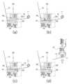
도 4는 본 발명의 실시예에 따른 기판 접착시트의 연속 공급장치에서 파지부재의 작동과정도,
도 5는 본 발명의 실시예에 따른 기판 접착시트의 연속 공급장치에서 절단부의 작동과정도,
도 6은 본 발명의 실시예에 따른 기판 접착시트의 연속 공급장치에서 롤이송부에 의해 공급롤이 전방으로 이동한 상태의 도면,
도 7은 본 발명의 실시예에 따른 기판 접착시트의 연속 공급장치에서 접합부의 작동과정도,
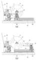
도 8은 본 발명의 실시예에 따른 기판 접착시트의 연속 공급장치에서 공급롤의 하강 및 후퇴과정을 도시한 작동과정도.1 is an overall structure diagram of an apparatus for continuously supplying a substrate adhesive sheet according to an embodiment of the present invention;
2 is a perspective view of a shaft support and a gripping member of a continuous supply device for a substrate adhesive sheet according to an embodiment of the present invention;
3 is an operation process of a shaft support in a continuous supplying device of a substrate adhesive sheet according to an embodiment of the present invention;
4 is an operation process of a holding member in a continuous supplying device for a substrate adhesive sheet according to an embodiment of the present invention;
5 is an operation process of a cutting unit in a continuous supplying device of a substrate adhesive sheet according to an embodiment of the present invention;
6 is a view of a state in which the supply roll is moved forward by the roll transfer unit in the device for continuously supplying the substrate adhesive sheet according to an embodiment of the present invention;
7 is an operation process of a bonding part in a continuous supplying device of a substrate adhesive sheet according to an embodiment of the present invention;
Figure 8 is an operating process showing the descending and retreating process of the supply roll in the continuous supplying device for the substrate adhesive sheet according to an embodiment of the present invention.
본 발명의 기판 접착시트의 연속 공급장치는 도 1에 도시된 바와 같이, 공급롤(10)과, 대차(20)와, 축지지대(30)와, 승강실린더(35)와, 파지부재(40)와, 회전구동부(49)와, 롤이송부(50)와, 접합부(60)와, 절단기(65), 고정지지대(70), 장력조절부(71)와, 축회수부재(72) 등을 포함하여 이루어진다.As shown in FIG. 1, the apparatus for continuously supplying the substrate adhesive sheet of the present invention includes a
상기 공급롤(10)은 기판을 접착하는 접착시트(15)가 지지축(11)을 중심으로 권취되어 형성된다.The
상기 접착시트(15)는 태양전지판 등과 같은 기판을 다수개 적층하여 상호 접착시킬때 사용된다.The
상기 접착시트(15)가 권취된 상기 지지축(11)은 상기 공급롤(10)의 양단방향으로 더 돌출되어 있다.The
이러한 상기 공급롤(10)은 작업자가 직접 설치할 수도 있지만, 본 실시예와 같이 상기 대차(20)를 이용하여 상기 공급롤(10)을 공급하도록 함이 바람직하다.Although the
상기 대차(20)에는 상기 공급롤(10)이 배치되고, 도 3에 도시된 바와 같이 상기 대차(20)의 이동에 의해 상기 공급롤(10)이 상기 축지지대(30)까지 공급되게 된다.The
상기 축지지대(30)는 상호 이격된 한 쌍으로 이루어지고, 상기 접착시트(15)가 권취되는 상기 지지축(11)을 지지하는 역할을 한다.The
즉, 상기 축지지대(30)는 상기 대차(20)를 통해 공급되는 공급롤(10)에서 상기 공급롤(10)의 양단방향으로 더 돌출된 상기 지지축(11)의 양측단을 받쳐 지지하게 된다.That is, the shaft support 30 supports and supports both ends of the
상기 승강실린더(35)는 상기 축지지대(30)를 상하방향으로 승강시킨다.The
상기 승강실린더(35)가 상기 축지지대(30)를 상하방향으로 승강시킴으로서, 상기 축지지대(30)에 받쳐 지지되는 상기 공급롤(10)은 상하방향으로 이동할 수 있게 된다.As the
상기 대차(20)의 이동에 의해 상기 축지지대(30)의 상부에 상기 지지축(11)이 배치되면, 상기 승강실린더(35)가 상기 축지지대(30)를 상승시켜 상기 공급롤(10)의 하면이 상기 대차(20)의 상면과 이격된 상태에서 상기 축지지대(30)가 상기 지지축(11)을 지지하게 된다.When the
이로 인해 상기 대차(20)를 후퇴시켜 새로운 공급롤(10)을 대차(20)에 다시 배치할 수 있게 된다.This makes it possible to retract the
상기 파지부재(40)는 도 4에 도시된 바와 같이 상기 접착시트(15)의 끝단을 파지한다.As shown in FIG. 4 , the gripping
상기 파지부재(40)는 상기 공급롤(10)의 외곽에 배치되고, 상기 회전구동부(49)에 의해 상기 파지부재(40)는 상기 공급롤(10)의 외곽을 따라 전후방향으로 회전한다.The
이러한 상기 파지부재(40)는 다양한 구성 및 구조로 이루어질 수 있다.The gripping
본 실시예에서 상기 파지부재(40)는 도 2에 도시된 바와 같이, 회전바(41)와, 회전연결바(42)와, 고정부재(43)를 포함하여 이루어진다.As shown in FIG. 2 , the
상기 회전바(41)는 한 쌍으로 이루어지고 상기 공급롤(10)의 양단 방향에서 한 쌍의 상기 축지지대(30)에 각각 회전 가능하게 결합된다.The rotating
상기 회전연결바(42)는 상기 공급롤(10)의 외곽에서 상기 지지축(11)과 동일한 방향으로 배치되면서 상호 이격되어 배치된 두 개의 상기 회전바(41)를 연결한다.The
2개의 상기 회전바(41)와 1개의 상기 회전연결바(42)에 의해 상기 파지부재(40)는 대략 '┌┐'와 같은 형상으로 이루어지게 된다.By the two
상기 고정부재(43)는 상기 회전연결바(42)에 장착되어 상기 접착시트(15)의 끝단을 고정시킨다.The
이러한 상기 고정부재(43)는 다양한 부품 및 구조로 이루어질 수 있다.The
예를 들어 상기 고정부재(43)는 진공흡착노즐로 이루어져 상기 접착시트(15)의 끝단을 흡착하여 고정시킬 수도 있고, 집게, 실린더, 바 등을 이용하여 상기 접착시트(15)의 끝단을 잡아 고정시킬 수도 있다.For example, the
상기 회전구동부(49)는 도 4에 도시된 바와 같이 상기 파지부재(40)를 전후방향으로 회전시킨다.As shown in FIG. 4 , the
보다 구체적으로, 상기 회전구동부(49)는 상기 파지부재(40)의 상기 회전바(41)를 전후방향으로 회전시키고, 상기 회전바(41)의 전후방향 회전에 의해 상기 회전연결바(42)는 상기 공급롤(10)의 전방 또는 후방에 배치되게 된다.More specifically, the
도 4(a)에 도시된 바와 같이 상기 공급롤(10)이 공급된 상태에서 상기 회전구동부(49)는 상기 파지부재(40)를 상기 공급롤(10)의 전방에서 후방으로 회전시켜 상기 파지부재(40)가 상기 공급롤(10)의 후방에서 상기 공급롤(10)의 끝단을 파지할 수 있도록 한다.As shown in FIG. 4( a ), in the state in which the
그리고 상기 파지부재(40)가 상기 접착시트(15)의 끝단을 파지한 상태에서 도 4(b)에 도시된 바와 같이 상기 회전구동부(49)는 상기 파지부재(40)를 상기 공급롤(10)의 후방에서 전방으로 회전 이동시킨다.And, as shown in FIG. 4(b) in a state in which the gripping
상기 롤이송부(50)는 상기 공급롤(10), 축지지대(30), 승강실린더(35) 및 파지부재(40) 등을 전후방향으로 직선 이동시킨다.The
도 6에 도시된 바와 같이 상기 파지부재(40)가 상기 접착시트(15)의 끝단을 파지한 상태에서 상기 롤이송부(50)는 상기 공급롤(10), 축지지대(30), 승강실린더(35) 및 파지부재(40) 등을 상기 접합부(60)가 배치된 전방으로 이송시킨다.As shown in FIG. 6 , in a state in which the gripping
이로 인해 상기 파지부재(40)에 의해 파지된 상기 접착시트(15)의 끝단은 전방에 배치되는 상기 접합부(60)에 배치되게 된다.As a result, the end of the
상기 접합부(60)는 도 7에 도시된 바와 같이 상기 파지부재(40)에 의해 파지된 상기 접착시트(15)의 끝단을 절단된 이전 접착시트(15)의 끝단과 연결한다.As shown in FIG. 7 , the
도 7(a)에 도시된 바와 같이 새롭게 공급되는 상기 접착시트(15)의 끝단이 상기 접합부(60)에 배치되면 상기 파지부재(40)는 상기 접착시트(15)의 끝단의 파지를 해제하여 상기 접착시트(15)의 끝단이 절단된 이전 접착시트(15)의 끝단과 중첩되게 한다.As shown in FIG. 7(a), when the end of the newly supplied
그 후 도 7(b) 및 (c)에 도시된 바와 같이, 상기 접합부(60)는 중첩된 접착시트(15)를 가압 및 열융착하여 일체로 연결하게 된다.After that, as shown in FIGS. 7(b) and (c), the
이러한 상기 접합부(60)는 도 7에 도시된 바와 같이, 받침부(61)와, 제1가압부(62)와, 제2가압부(63)와, 초음파융착기(64)를 포함하여 이루어진다.As shown in FIG. 7 , the
상기 받침부(61)는 상부에 절단된 이전 접착시트(15)의 끝단과 새롭게 공급되는 접착시트(15)의 끝단이 배치된다.The
상기 제1가압부(62)는 도 7(a)에 도시된 바와 같이 이미 하강하여 절단된 이전 접착시트(15)를 상기 받침부(61)로 가압하고 있다.As shown in FIG. 7(a), the first
상기 제2가압부(63)는 하강하면서, 도 7(b)에 도시된 바와 같이 중첩되어 배치되는 절단된 이전 접착시트(15)의 끝단과 새롭게 공급되는 접착시트(15)의 끝단을 함께 가압한다.As the second
상기 초음파융착기(64)는 도 7(c)에 도시된 바와 같이, 상기 받침부(61)를 따라 이동하면서 중첩된 접착시트(15)를 접합시킨다.As shown in FIG. 7(c), the
상기 절단기(65)는 도 5에 도시된 바와 같이 상기 공급롤(10)에 권취되어 있는 접착시트(15)를 절단하는 기능을 한다.As shown in FIG. 5 , the
상기 절단기(65)는 도 5(b)에 도시된 바와 같이 상기 제1가압부(62) 및 제2가압부(63)가 접착시트(15)를 가압한 상태에서, 도 5(c)에 도시된 바와 같이 상승한 후 상기 받침부(61)를 따라 이동하여 상기 접착시트(15)를 절단한다.As shown in FIG. 5(b), the cutting
상기 고정지지대(70)는 상기 접합부(60)의 후방에 배치되어, 도 8에 도시된 바와 같이 상기 롤이송부(50)를 통해 전방으로 이동된 상기 공급롤(10)의 지지축(11)을 지지한다.The fixed
상기 접착시트(15)가 권취되어 있는 상기 지지축(11)은, 상술한 바와 같이 상기 승강실린더(35)에 의한 상기 축지지대(30)의 상하방향 이동과, 상기 롤이송부(50)에 의한 전후방향 이동에 의해 상기 축지지대(30)에서 상기 고정지지대(70)로 옮겨져 지지된 후, 권취되어 있는 상기 접착시트(15)가 연속적으로 인출되게 된다.As described above, the
상기 장력조절부(71)는 상기 접합부(60)의 전방에 배치되어 상기 공급롤(10)에서 인출되는 상기 접착시트(15)의 장력을 일정하게 유지시키면서 외부로 배출시킨다.The
상기 축회수부재(72)는 상기 지지축(11)에 권취되어 있는 접착시트(15)의 인출이 완료되면 상기 고정지지대(70)에 놓여 있는 상기 지지축(11)을 회수한다.The
이하, 상술한 구성으로 이루어진 본 발명의 작동과정에 대하여 살펴본다.Hereinafter, the operation process of the present invention consisting of the above-described configuration will be looked at.
본 발명의 기판 접착시트 연속 공급방법은, 롤공급단계(S1)와, 축지지단계(S2)와, 파지단계(S3)와, 파지회전단계(S4)와, 절단단계(S5)와, 축회수단계(S6)와, 롤이송단계(S7)와, 접합단계(S8)와, 롤하강단계(S9)와, 후퇴단계(S10)와, 인출단계(S11)를 포함하여 이루어진다.The substrate adhesive sheet continuous supply method of the present invention includes a roll supply step (S1), a shaft support step (S2), a gripping step (S3), a gripping rotation step (S4), a cutting step (S5), a shaft It includes a recovery step (S6), a roll transfer step (S7), a joining step (S8), a roll lowering step (S9), a retraction step (S10), and a withdrawal step (S11).
상기 롤공급단계(S1)는 기판을 접착하는 접착시트(15)가 지지축(11)을 중심으로 권취되어 있는 상기 공급롤(10)을 공급하는 단계이다.The roll supply step (S1) is a step of supplying the
이때 본 실시예에서는 도 3(a)에 도시된 바와 같이 상기 대차(20)를 이용하여 상기 공급롤(10)을 상기 축지지대(30)까지 이동하여 공급하게 된다.At this time, in this embodiment, as shown in FIG. 3 (a), the
상기 축지지단계(S2)는 상기 축지지대(30)로 상기 공급롤(10)의 지지축(11)을 지지하는 단계이다.The shaft support step (S2) is a step of supporting the
상기 대차(20)를 통해 공급된 상기 공급롤(10)은 상기 축지지대(30)에 옮겨져 지지되게 된다.The
보다 구체적으로, 도 3(a)에 도시된 바와 같이 상기 축지지단계(S2)에서는 상기 대차(20)의 이동에 의해 상기 축지지대(30)의 상부에 상기 지지축(11)이 배치되면, 도 3(b)에 도시된 바와 같이 상기 승강실린더(25)에 의해 상기 축지지대(30)를 상승시켜 상기 공급롤(10)의 하면이 상기 대차(20)의 상면과 이격된 상태에서 상기 축지지대(30)가 상기 지지축(11)을 지지하도록 한다.More specifically, as shown in FIG. 3 (a), in the shaft support step (S2), when the
상기 파지단계(S3)는 상기 공급롤(10)에 권취되어 있는 상기 접착시트(15)의 끝단을 파지부재(40)로 파지하는 단계이다.The gripping step (S3) is a step of gripping the end of the
상기 파지단계(S3)는 도 4(a)에 도시된 바와 같이 상기 공급롤(10)이 공급된 상태에서 상기 공급롤(10)의 외곽에 배치되는 상기 파지부재(40)를 전방에서 후방향으로 회전시켜 상기 공급롤(10)의 후방에서 상기 파지부재(40)가 상기 공급롤(10)의 끝단을 파지하게 된다.As shown in FIG. 4(a), the gripping step (S3) moves the gripping
상기 파지회전단계(S4)는 도 4(b)에 도시된 바와 같이 상기 파지부재(40)가 상기 접착시트(15)의 끝단을 파지한 상태에서 상기 파지부재(40)를 상기 공급롤(10)의 후방에서 전방으로 회전시켜 상기 접착시트(15)의 끝단이 상기 접합부(60)가 배치되는 상기 공급롤(10)의 전방으로 이동 배치되도록 한다.In the gripping rotation step (S4), as shown in FIG. 4(b), the gripping
상기 절단단계(S5)는 도 5에 도시된 바와 같이, 미리 공급된 공급롤(10)에서 상기 지지축(11)에 권취되어 있는 상기 접착시트(15)가 미리 설정된 만큼 인출되면 상기 접착시트(15)를 절단하는 단계이다.As shown in FIG. 5, in the cutting step (S5), when the
상기 절단단계(S5)에서는 상기 파지회전단계(S4)에서 사용된 새로운 공급롤(10)의 접착시트(15)를 절단하는 것이 아니라, 미리 공급되어 인출되고 있는 공급롤(10)에서 접착시트(15)를 절단하는 단계이다.In the cutting step (S5), the
도 5(a)에 도시된 바와 같은 상태에서 상기 접착시트(15)를 절단하고자 할 경우, 상기 절단단계(S5)에서는 도 5(b)에 도시된 바와 같이 상기 제1가압부(62)와 제2가압부(63)를 모두 하강시켜 상기 접착시트(15)를 가압하여 고정시킨다.In the case of cutting the
그 후 도 5(c)에 도시된 바와 같이 상기 절단기(65)가 상승한 후 측방향으로 이동하여 상기 접착시트(15)를 절단한다.After that, as shown in FIG. 5(c), the
그 다음 도 5(d)에 도시된 바와 같이 상기 제2가압부(63)가 상승하고 상기 절단기(65)가 하강한다.Then, as shown in FIG. 5(d), the second
이로 인해 절단된 상기 접착시트(15)는 상기 제1가압부(62)에 의해 눌려 이동됨이 없이 고정된 상태를 유지하게 되고, 상기 제2가압부(63)의 하부에는 절단된 접착시트(15)가 상기 받침부(61)의 상부에서 외부로 노출된 상태에 놓여 있게 된다.As a result, the cut
상기 절단단계(S5)에 의해 절단된 접착시트(15)의 끝단은 후술하는 바와 같이 상기 접합단계(S8)를 통해 새롭게 공급되는 접착시트(15)의 끝단과 연결되어 전방으로 연속적으로 인출 공급되게 된다.As will be described later, the end of the
상기 축회수단계(S6)는 도 5(d)에 도시된 바와 같이 상기 지지축(11)에 권취되어 있는 접착시트(15)의 인출이 완료되면, 상기 절단단계(S5) 이후에 상기 고정지지대(70)에 놓여 있는 상기 지지축(11)을 회수하는 단계이다.As shown in FIG. 5(d), in the shaft recovery step (S6), when the withdrawal of the
상기 롤이송단계(S7)는 상기 절단단계(S5) 및 축회수단계(S6) 이후에 상기 파지부재(40)에 의해 상기 접착시트(15)의 끝단이 파지된 상기 공급롤(10)을 도 6에 도시된 바와 같이 전방으로 이동시킨다.In the roll transfer step (S7), after the cutting step (S5) and the shaft recovery step (S6), the
상기 롤이송단계(S7)에서는 상기 파지부재(40)가 상기 접착시트(15)의 끝단을 파지한 상태에서 상기 공급롤(10), 축지지대(30), 승강실린더(35) 및 파지부재(40)를 전방으로 이송시켜 상기 접착시트(15)의 끝단이 상기 접합부(60)에 배치되도록 한다.In the roll transfer step (S7), the
이때 상기 롤이송단계(S7)에서는 상기 파지부재(40)에 의해 파지된 상기 접착시트(15)의 끝단이 상기 접합부(60)를 구성하는 상기 제2가압부(63)의 하부에 배치되도록 한다.At this time, in the roll transfer step (S7), the end of the
상기 접합단계(S8)는 도 7에 도시된 바와 같이, 상기 접착시트(15)의 끝단의 파지를 해제하고, 상기 롤이송단계(S7)에 의해 전방으로 이동된 접착시트(15)의 끝단과 상기 절단단계(S5)에 의해 절단된 이전 접착시트(15)의 끝단을 접합부(60)에서 연결하는 단계이다.As shown in FIG. 7, in the bonding step (S8), gripping of the end of the
이러한 상기 접합단계(S8)는 중첩배치단계(S81)와, 가압단계(S82)와, 해제단계(S83)와, 융착단계(S84)를 포함하여 이루어진다.The joining step (S8) includes an overlapping arrangement step (S81), a pressing step (S82), a release step (S83), and a fusion step (S84).
상기 중첩배치단계(S81)에서는 도 7(a)에 도시된 바와 같이 상기 롤이송단계(S7)에 의해 전방으로 이송된 상기 접착시트(15)의 끝단을 상기 제2가압부(63)의 하부에 배치되게 한다.In the overlapping arrangement step (S81), as shown in FIG. 7(a), the end of the
이때 상기 받침부(61)의 상부에는 상기 절단단계(S5)에 의해 절단된 이전 접착시트(15)가 이미 배치되어 있기 때문에, 상기 중첩배치단계(S81)에서는 절단된 이전 접착시트(15)의 상부에 새롭게 공급되는 접착시트(15)의 끝단이 중첩되어 배치되게 된다.At this time, since the previous
상기 가압단계(S82)는 상기 중첩배치단계(S81) 이후에 도 7(b)에 도시된 바와 같이 중첩된 접착시트(15)를 상기 제2가압부(63)가 하강하여 함께 가압하는 단계이다.The pressing step (S82) is a step in which the second
상기 해제단계(S83)는 상기 접착시트(15)의 끝단을 파지하고 있는 상기 파지부재(40)의 파지를 해제하는 단계이다.The releasing step (S83) is a step of releasing the gripping of the gripping
상기 융착단계(S84)는 상기 해제단계(S83) 이후에 도 7(c)에 도시된 바와 같이 상기 초음파융착기(64)가 상승하여 중첩된 접착시트(15)를 열융착하여 접합시키는 단계이다.The fusion step (S84) is a step in which the
위와 같이 상기 융착단계(S84)가 완료되면 이전 접착시트(15)와 새롭게 공급된 접착시트(15)는 융착되어 하나로 연결되게 된다.As described above, when the fusion step (S84) is completed, the previous
그 후 도 7(d)에 도시된 바와 같이 상기 제1가압부(62) 및 제2가압부(63)는 상승하고 상기 초음파융착기(64)는 하강하게 된다.After that, as shown in FIG. 7(d), the first
경우에 따라 상기 해제단계(S83)는 그 작업 순서가 다른 단계의 순서와 변경될 수도 있다.In some cases, the order of the release step (S83) may be changed from the order of other steps.
상기 롤하강단계(S9)는 도 8(a)에 도시된 바와 같이 상승된 상기 축지지대(30)를 하강시켜 상기 공급롤(10)의 지지축(11)을 상기 고정지지대(70)에서 지지하도록 한다.In the roll lowering step (S9), as shown in FIG. 8(a), the
즉, 상기 롤하강단계(S9)에 의해 상기 지지축(11)은 상기 축지지대(30)에서 상기 고정지지대(70)로 옮겨져 지지되게 된다.That is, the
상기 후퇴단계(S10)는 도 8(b)에 도시된 바와 같이 하강된 상기 축지지대(30) 및 파지부재(40) 등 원위치인 후방으로 이동시키는 단계이다.The retracting step (S10) is a step of moving the
상기 롤하강단계(S9)와 후퇴단계(S10)는 상기 접합단계(S8) 이후에 이루어질 수도 있고, 경우에 따라 상기 접합단계(S8) 과정에서 상기 해제단계(S83) 이후에 이루어질 수도 있다.The roll descending step (S9) and the retreating step (S10) may be performed after the joining step (S8), or may be performed after the releasing step (S83) in the joining step (S8) according to circumstances.
상기 인출단계(S11)는 상기 공급롤(10)에서 상기 접착시트(15)를 전방으로 인출하여 공급하는 단계이다.The withdrawing step (S11) is a step of withdrawing and supplying the
위와 같이 본 발명은 상기 공급롤(10)에서 공급되는 접착시트(15)를 자동으로 연결한 후 공급하도록 함으로서, 접착시트(15)가 끊김없이 연속적으로 공급되도록 할 수 있다.As described above, the present invention automatically connects and then supplies the
본 발명인 기판 접착시트의 연속 공급장치는 전술한 실시예에 국한하지 않고, 본 발명의 기술 사상이 허용되는 범위 내에서 다양하게 변형하여 실시할 수 있다.The continuous supplying device of the substrate adhesive sheet according to the present invention is not limited to the above-described embodiment, and may be variously modified and implemented within the scope permitted by the technical idea of the present invention.
10 : 공급롤, 11 : 지지축, 15 : 접착시트,
20 : 대차, 30 : 축지지대, 35 : 승강실린더,
40 : 파지부재, 41 : 회전바, 42 : 회전연결바, 43 : 고정부재, 49 : 회전구동부,
50 : 롤이송부,
60 : 접합부, 61 : 받침부, 62 : 제1가압부, 63 : 제2가압부, 64 : 초음파융착기, 65 : 절단기,
70 : 고정지지대, 71 : 장력조절부, 72 : 축회수부재,
S1 : 롤공급단계, S2 : 축지지단계, S3 : 파지단계, S4 : 파지회전단계,
S5 : 절단단계, S6 : 축회수단계, S7 : 롤이송단계,
S8 : 접합단계, S81 : 중첩배치단계, S82 : 가압단계, S83 : 해제단계, S84 : 융착단계,
S9 : 롤하강단계, S10 : 후퇴단계, S11 : 인출단계.10: supply roll, 11: support shaft, 15: adhesive sheet,
20: bogie, 30: shaft support, 35: lift cylinder,
40: holding member, 41: rotation bar, 42: rotation connection bar, 43: fixing member, 49: rotation drive unit,
50: roll transfer unit,
60: joining part, 61: supporting part, 62: first pressing part, 63: second pressing part, 64: ultrasonic welding machine, 65: cutting machine,
70: fixed support, 71: tension control unit, 72: shaft recovery member,
S1: roll supply step, S2: shaft support step, S3: gripping step, S4: gripping rotation step,
S5: cutting step, S6: shaft recovery step, S7: roll transfer step,
S8: joining step, S81: overlapping arrangement step, S82: pressing step, S83: release step, S84: fusion step,
S9: roll descending step, S10: retracting step, S11: withdrawing step.
Claims (10)
Translated fromKorean상기 지지축을 지지하는 한 쌍의 축지지대와;
상기 접착시트의 끝단을 파지하는 파지부재와;
상기 공급롤, 축지지대 및 파지부재를 직선 이동시키는 롤이송부와;
상기 파지부재에 의해 파지된 상기 접착시트의 끝단을 절단된 이전 접착시트의 끝단과 연결하는 접합부와;
상기 공급롤에 권취되어 있는 접착시트를 절단하는 절단기와;
상기 공급롤을 공급하는 대차와;
상기 축지지대를 상하방향으로 승강시키는 승강실린더;를 포함하여 이루어지되,
상기 파지부재가 상기 접착시트의 끝단을 파지한 상태에서 상기 롤이송부는 상기 공급롤, 축지지대 및 파지부재를 상기 접합부가 배치된 전방으로 이송시키고,
상기 접착시트의 끝단이 상기 접합부에 배치되면 상기 파지부재는 상기 접착시트의 끝단의 파지를 해제하여 상기 접착시트의 끝단이 절단된 이전 접착시트의 끝단과 중첩되게 하며,
상기 접합부는 중첩된 접착시트를 열융착하여 연결하며,
상기 지지축은 상기 공급롤의 양단방향으로 더 돌출되어 있고,
상기 대차의 이동에 의해 상기 축지지대의 상부에 상기 지지축이 배치되면, 상기 승강실린더가 상기 축지지대를 상승시켜 상기 공급롤의 하면이 상기 대차의 상면과 이격된 상태에서 상기 축지지대가 상기 지지축을 지지하게 되는 것을 특징으로 하는 기판 접착시트의 연속 공급장치.a supply roll in which an adhesive sheet for bonding a substrate is wound around a support shaft;
a pair of shaft supports for supporting the support shaft;
a gripping member gripping an end of the adhesive sheet;
a roll transfer unit for linearly moving the supply roll, the shaft support, and the holding member;
a junction part connecting the end of the adhesive sheet held by the holding member to the end of the previously cut adhesive sheet;
a cutter for cutting the adhesive sheet wound around the supply roll;
a truck for supplying the supply roll;
It is made to include; an elevating cylinder for elevating the shaft support in the vertical direction,
In a state in which the gripping member grips the end of the adhesive sheet, the roll transfer unit transfers the supply roll, the shaft support, and the gripping member to the front where the junction is disposed,
When the end of the adhesive sheet is disposed at the junction, the gripping member releases the grip of the end of the adhesive sheet so that the end of the adhesive sheet overlaps the end of the previously cut adhesive sheet,
The bonding part connects the overlapping adhesive sheets by thermal fusion,
The support shaft further protrudes in both ends of the supply roll,
When the support shaft is disposed above the shaft support by the movement of the bogie, the lift cylinder raises the shaft support so that the shaft support supports the shaft support in a state where the lower surface of the supply roll is spaced apart from the upper surface of the carriage. Continuous feeding device of the substrate adhesive sheet, characterized in that to support the shaft.
상기 지지축을 지지하는 한 쌍의 축지지대와;
상기 접착시트의 끝단을 파지하는 파지부재와;
상기 공급롤, 축지지대 및 파지부재를 직선 이동시키는 롤이송부와;
상기 파지부재에 의해 파지된 상기 접착시트의 끝단을 절단된 이전 접착시트의 끝단과 연결하는 접합부와;
상기 공급롤에 권취되어 있는 접착시트를 절단하는 절단기와;
상기 파지부재를 회전시키는 회전구동부;를 포함하여 이루어지되,
상기 파지부재가 상기 접착시트의 끝단을 파지한 상태에서 상기 롤이송부는 상기 공급롤, 축지지대 및 파지부재를 상기 접합부가 배치된 전방으로 이송시키고,
상기 접착시트의 끝단이 상기 접합부에 배치되면 상기 파지부재는 상기 접착시트의 끝단의 파지를 해제하여 상기 접착시트의 끝단이 절단된 이전 접착시트의 끝단과 중첩되게 하며,
상기 접합부는 중첩된 접착시트를 열융착하여 연결하며,
상기 파지부재는 상기 공급롤의 외곽에 배치되고,
상기 회전구동부에 의해 상기 파지부재는 상기 공급롤의 외곽을 따라 전후방향으로 회전하며,
상기 공급롤이 공급된 상태에서 상기 회전구동부는 상기 파지부재를 상기 공급롤의 후방으로 회전시켜 상기 파지부재가 상기 공급롤의 후방에서 상기 공급롤의 끝단을 파지하도록 하는 것을 특징으로 하는 기판 접착시트의 연속 공급장치.a supply roll in which an adhesive sheet for bonding a substrate is wound around a support shaft;
a pair of shaft supports for supporting the support shaft;
a gripping member gripping an end of the adhesive sheet;
a roll transfer unit for linearly moving the supply roll, the shaft support, and the holding member;
a junction part connecting the end of the adhesive sheet held by the holding member to the end of the previously cut adhesive sheet;
a cutter for cutting the adhesive sheet wound around the supply roll;
It is made to include; a rotation drive unit for rotating the gripping member,
In a state in which the gripping member grips the end of the adhesive sheet, the roll transfer unit transfers the supply roll, the shaft support, and the gripping member to the front where the junction is disposed,
When the end of the adhesive sheet is disposed at the junction, the gripping member releases the grip of the end of the adhesive sheet so that the end of the adhesive sheet overlaps the end of the previously cut adhesive sheet,
The bonding part connects the overlapping adhesive sheets by thermal fusion,
The holding member is disposed outside the supply roll,
The holding member is rotated in the forward and backward directions along the outer periphery of the supply roll by the rotary driving unit,
In a state in which the supply roll is supplied, the rotary driving unit rotates the holding member to the rear of the supply roll so that the holding member grips the end of the supply roll at the rear of the supply roll. continuous supply of
상기 파지부재는,
상기 공급롤의 양단 방향에서 상기 축지지대에 회전 가능하게 결합되는 한 쌍의 회전바와;
상기 공급롤의 외곽에서 상기 지지축과 동일한 방향으로 배치되면서 상호 이격되어 배치된 두 개의 상기 회전바를 연결하는 회전연결바와;
상기 회전연결바에 장착되어 상기 접착시트의 끝단을 고정시키는 고정부재;를 포함하여 이루어지되,
상기 회전구동부는 상기 회전바를 전후방향으로 회전시키고,
상기 회전바의 전후방향 회전에 의해 상기 회전연결바는 상기 공급롤의 전방 또는 후방에 배치되게 되는 것을 특징으로 하는 기판 접착시트의 연속 공급장치.In claim 3,
The holding member,
a pair of rotating bars rotatably coupled to the shaft support at both ends of the supply roll;
a rotation connecting bar connecting the two rotation bars spaced apart from each other while being disposed in the same direction as the support shaft at the periphery of the supply roll;
A fixing member mounted on the rotating connecting bar to fix the end of the adhesive sheet;
The rotary drive unit rotates the rotary bar in the forward and backward directions,
The continuous supply device of the substrate adhesive sheet, characterized in that the rotation connecting bar is disposed in the front or rear of the supply roll by the forward and backward rotation of the rotation bar.
상기 파지부재가 상기 접착시트의 끝단을 파지한 상태에서 상기 회전구동부는 상기 파지부재를 상기 공급롤의 후방에서 전방으로 회전 이동시키고,
상기 롤이송부는 상기 공급롤, 축지지대 및 파지부재를 상기 접합부가 배치된 전방으로 이송시켜 상기 접착시트의 끝단이 상기 접합부에 배치되도록 하는 것을 특징으로 하는 기판 접착시트의 연속 공급장치.In claim 3,
In a state in which the gripping member grips the end of the adhesive sheet, the rotary driving unit rotates the gripping member from the rear to the front of the supply roll,
The roll transfer unit transfers the supply roll, the shaft support, and the holding member to the front where the junction is disposed so that the end of the adhesive sheet is disposed at the junction.
상기 지지축을 지지하는 한 쌍의 축지지대와;
상기 접착시트의 끝단을 파지하는 파지부재와;
상기 공급롤, 축지지대 및 파지부재를 직선 이동시키는 롤이송부와;
상기 파지부재에 의해 파지된 상기 접착시트의 끝단을 절단된 이전 접착시트의 끝단과 연결하는 접합부와;
상기 공급롤에 권취되어 있는 접착시트를 절단하는 절단기;를 포함하여 이루어지되,
상기 파지부재가 상기 접착시트의 끝단을 파지한 상태에서 상기 롤이송부는 상기 공급롤, 축지지대 및 파지부재를 상기 접합부가 배치된 전방으로 이송시키고,
상기 접착시트의 끝단이 상기 접합부에 배치되면 상기 파지부재는 상기 접착시트의 끝단의 파지를 해제하여 상기 접착시트의 끝단이 절단된 이전 접착시트의 끝단과 중첩되게 하며,
상기 접합부는 중첩된 접착시트를 열융착하여 연결하며,
상기 접합부는,
상부에 절단된 이전 접착시트의 끝단과 새롭게 공급되는 접착시트의 끝단이 배치되는 받침부와;
절단된 이전 접착시트를 상기 받침부로 가압하는 제1가압부와;
중첩되어 배치되는 절단된 이전 접착시트의 끝단과 새롭게 공급되는 접착시트의 끝단을 가압하는 제2가압부와;
상기 받침부를 따라 이동하면서 중첩된 접착시트를 접합시키는 초음파융착기;를 포함하여 이루어진 것을 특징으로 하는 기판 접착시트의 연속 공급장치.a supply roll in which an adhesive sheet for bonding a substrate is wound around a support shaft;
a pair of shaft supports for supporting the support shaft;
a gripping member gripping an end of the adhesive sheet;
a roll transfer unit for linearly moving the supply roll, the shaft support, and the holding member;
a junction part connecting the end of the adhesive sheet held by the holding member to the end of the previously cut adhesive sheet;
A cutting machine for cutting the adhesive sheet wound around the supply roll;
In a state in which the gripping member grips the end of the adhesive sheet, the roll transfer unit transfers the supply roll, the shaft support, and the gripping member to the front where the junction is disposed,
When the end of the adhesive sheet is disposed at the junction, the gripping member releases the grip of the end of the adhesive sheet so that the end of the adhesive sheet overlaps the end of the previously cut adhesive sheet,
The bonding part connects the overlapping adhesive sheets by thermal fusion,
The junction is
a support portion on which the ends of the previously cut adhesive sheets and the ends of the newly supplied adhesive sheets are disposed;
a first pressing unit for pressing the previous cut adhesive sheet to the supporting unit;
a second pressing unit which presses an end of the previously cut adhesive sheet and an end of the newly supplied adhesive sheet, which overlap each other;
Continuous supply of substrate adhesive sheets characterized in that it comprises a; ultrasonic fusion machine for bonding the overlapping adhesive sheets while moving along the supporting portion.
상기 절단기는 상기 제1가압부 및 제2가압부가 접착시트를 가압한 상태에서 상기 받침부를 따라 이동하여 상기 접착시트를 절단하는 것을 특징으로 하는 기판 접착시트의 연속 공급장치.In claim 6,
The cutter continuously feeds the substrate adhesive sheet, characterized in that the first pressing unit and the second pressing unit move along the supporting portion to cut the adhesive sheet in a state in which the adhesive sheet is pressed.
상기 접합부의 후방에 배치되어 상기 롤이송부를 통해 전방으로 이동된 상기 공급롤의 지지축을 지지하는 고정지지대;를 더 포함하여 이루어지되,
상기 지지축은 상기 축지지대의 상하방향 이동과 상기 롤이송부에 의한 전후방향 이동에 의해 상기 축지지대에서 상기 고정지지대로 옮겨져 지지되는 것을 특징으로 하는 기판 접착시트의 연속 공급장치.In claim 6,
A fixed support disposed at the rear of the joint and supporting the support shaft of the supply roll moved forward through the roll transfer unit; further comprising,
The support shaft is a continuous supply device for substrate adhesive sheet, characterized in that moved from the shaft support to the fixed support by the vertical movement of the shaft support and the forward and backward movement by the roll transfer unit.
상기 접합부의 전방에 배치되어 상기 공급롤에서 인출되는 상기 접착시트의 장력을 일정하게 유지시키면서 외부로 배출시키는 장력조절부;를 더 포함하여 이루어진 것을 특징으로 하는 기판 접착시트의 연속 공급장치.The method according to any one of claims 2, 3 or 6,
The apparatus for continuously supplying the substrate adhesive sheet, characterized in that it further comprises: a tension control unit disposed in front of the bonding unit and discharging the adhesive sheet to the outside while maintaining a constant tension of the adhesive sheet drawn out from the supply roll.
상기 지지축에 권취되어 있는 접착시트의 인출이 완료되면 상기 고정지지대에 놓여 있는 상기 지지축을 회수하는 축회수부재;를 더 포함하여 이루어진 것을 특징으로 하는 기판 접착시트의 연속 공급장치.In claim 8,
The device for supplying the substrate adhesive sheet continuously, characterized in that it further comprises: a shaft recovery member for recovering the support shaft placed on the fixed support when the withdrawal of the adhesive sheet wound around the support shaft is completed.
Priority Applications (1)
| Application Number | Priority Date | Filing Date | Title |
|---|---|---|---|
| KR1020220065313AKR102520602B1 (en) | 2022-05-27 | 2022-05-27 | Continuous supply apparatus of adhesive sheet |
Applications Claiming Priority (1)
| Application Number | Priority Date | Filing Date | Title |
|---|---|---|---|
| KR1020220065313AKR102520602B1 (en) | 2022-05-27 | 2022-05-27 | Continuous supply apparatus of adhesive sheet |
Publications (1)
| Publication Number | Publication Date |
|---|---|
| KR102520602B1true KR102520602B1 (en) | 2023-04-11 |
Family
ID=85976663
Family Applications (1)
| Application Number | Title | Priority Date | Filing Date |
|---|---|---|---|
| KR1020220065313AActiveKR102520602B1 (en) | 2022-05-27 | 2022-05-27 | Continuous supply apparatus of adhesive sheet |
Country Status (1)
| Country | Link |
|---|---|
| KR (1) | KR102520602B1 (en) |
Citations (6)
| Publication number | Priority date | Publication date | Assignee | Title |
|---|---|---|---|---|
| US5692698A (en)* | 1996-02-05 | 1997-12-02 | Forbes; Thomas J. | Web feeding and transition assembly |
| JP2001322751A (en)* | 2000-05-17 | 2001-11-20 | Dainippon Printing Co Ltd | Web linking device |
| KR101070871B1 (en) | 2010-10-13 | 2011-10-06 | 에플럭스(주) | Solar Cell Back Module |
| KR101181053B1 (en)* | 2012-02-23 | 2012-09-07 | (주)지엠티 | System to lap and to load profiles automatically |
| KR20120109206A (en) | 2011-03-28 | 2012-10-08 | 동우 화인켐 주식회사 | Adhesive layer for solar cell backside protective sheet and manufacturing method thereof |
| KR102120098B1 (en)* | 2020-01-03 | 2020-06-08 | 세종기술 주식회사 | Tape Continuous Feeding Apparatus and Method for Continuous Feeding of Tape |
- 2022
- 2022-05-27KRKR1020220065313Apatent/KR102520602B1/enactiveActive
Patent Citations (6)
| Publication number | Priority date | Publication date | Assignee | Title |
|---|---|---|---|---|
| US5692698A (en)* | 1996-02-05 | 1997-12-02 | Forbes; Thomas J. | Web feeding and transition assembly |
| JP2001322751A (en)* | 2000-05-17 | 2001-11-20 | Dainippon Printing Co Ltd | Web linking device |
| KR101070871B1 (en) | 2010-10-13 | 2011-10-06 | 에플럭스(주) | Solar Cell Back Module |
| KR20120109206A (en) | 2011-03-28 | 2012-10-08 | 동우 화인켐 주식회사 | Adhesive layer for solar cell backside protective sheet and manufacturing method thereof |
| KR101181053B1 (en)* | 2012-02-23 | 2012-09-07 | (주)지엠티 | System to lap and to load profiles automatically |
| KR102120098B1 (en)* | 2020-01-03 | 2020-06-08 | 세종기술 주식회사 | Tape Continuous Feeding Apparatus and Method for Continuous Feeding of Tape |
Similar Documents
| Publication | Publication Date | Title |
|---|---|---|
| JP4514829B2 (en) | Working device, adhesive tape attaching device, and method for adding tape member | |
| JP4549432B2 (en) | Adhesive tape attaching device and tape connecting method | |
| CN104972246A (en) | Carriage plate robot welding automatic production line | |
| JP4658234B2 (en) | Adhesive tape affixing device, crimping device, adhesive tape affixing method and crimping method | |
| CN108574023A (en) | A photovoltaic battery string repair device | |
| KR20050001006A (en) | A Both Faces Tape Auto Taping Apparatus | |
| CN115092742A (en) | Splicing device for blister packaging lines | |
| CN108328388A (en) | A kind of automatic refueling machine of the film producing poly-bag | |
| KR102520602B1 (en) | Continuous supply apparatus of adhesive sheet | |
| KR102508371B1 (en) | Continuous supply method of adhesive sheet | |
| KR102192068B1 (en) | Automatic Tape Supply for Electrode Plate Automatic Adhesion of Lithium-ion Battery | |
| CN105870251A (en) | Attaching device for viscous solar battery welding strip | |
| KR20110008177A (en) | Sheet pasting device and pasting method | |
| CN214873059U (en) | Non-stop reel changing mechanism of bag making machine | |
| JP2017075036A (en) | Web splicing method and web splicing device | |
| JP4474396B2 (en) | Rubber sheet joining method and joining apparatus | |
| CN114474699B (en) | Technology for increasing PT film on flexible circuit board cover film | |
| CN117558964A (en) | Integrated production device for integrated battery cell electrode group | |
| CN211222375U (en) | Automatic compounding device for thermal compounding of non-woven fabric and polyurethane sheet | |
| CN210415561U (en) | A child base coiled material connecting device for producing waterproofing membrane | |
| KR102450202B1 (en) | Ear loop joining apparatus for mask | |
| JPS6054641B2 (en) | Automatic continuous pasting method of adhesive polarizing plate to cells | |
| JP3738603B2 (en) | ACF sticking device | |
| CN210653976U (en) | Labeling device | |
| KR20060014667A (en) | Protective tape attachment device |
Legal Events
| Date | Code | Title | Description |
|---|---|---|---|
| PA0109 | Patent application | Patent event code:PA01091R01D Comment text:Patent Application Patent event date:20220527 | |
| PA0201 | Request for examination | ||
| PA0302 | Request for accelerated examination | Patent event date:20220531 Patent event code:PA03022R01D Comment text:Request for Accelerated Examination Patent event date:20220527 Patent event code:PA03021R01I Comment text:Patent Application | |
| PE0902 | Notice of grounds for rejection | Comment text:Notification of reason for refusal Patent event date:20221223 Patent event code:PE09021S01D | |
| E701 | Decision to grant or registration of patent right | ||
| PE0701 | Decision of registration | Patent event code:PE07011S01D Comment text:Decision to Grant Registration Patent event date:20230327 | |
| GRNT | Written decision to grant | ||
| PR0701 | Registration of establishment | Comment text:Registration of Establishment Patent event date:20230406 Patent event code:PR07011E01D | |
| PR1002 | Payment of registration fee | Payment date:20230407 End annual number:3 Start annual number:1 | |
| PG1601 | Publication of registration |