KR102519139B1 - Apparatus and Method for Electric Field Therapy using Rotating Electric Fields - Google Patents
Apparatus and Method for Electric Field Therapy using Rotating Electric FieldsDownload PDFInfo
- Publication number
- KR102519139B1 KR102519139B1KR1020200160333AKR20200160333AKR102519139B1KR 102519139 B1KR102519139 B1KR 102519139B1KR 1020200160333 AKR1020200160333 AKR 1020200160333AKR 20200160333 AKR20200160333 AKR 20200160333AKR 102519139 B1KR102519139 B1KR 102519139B1
- Authority
- KR
- South Korea
- Prior art keywords
- electric field
- envelope
- frequency
- target region
- rotating
- Prior art date
- Legal status (The legal status is an assumption and is not a legal conclusion. Google has not performed a legal analysis and makes no representation as to the accuracy of the status listed.)
- Active
Links
Images


Classifications
- A—HUMAN NECESSITIES
- A61—MEDICAL OR VETERINARY SCIENCE; HYGIENE
- A61N—ELECTROTHERAPY; MAGNETOTHERAPY; RADIATION THERAPY; ULTRASOUND THERAPY
- A61N1/00—Electrotherapy; Circuits therefor
- A61N1/40—Applying electric fields by inductive or capacitive coupling ; Applying radio-frequency signals
- A—HUMAN NECESSITIES
- A61—MEDICAL OR VETERINARY SCIENCE; HYGIENE
- A61N—ELECTROTHERAPY; MAGNETOTHERAPY; RADIATION THERAPY; ULTRASOUND THERAPY
- A61N1/00—Electrotherapy; Circuits therefor
- A61N1/18—Applying electric currents by contact electrodes
- A61N1/32—Applying electric currents by contact electrodes alternating or intermittent currents
- A61N1/36—Applying electric currents by contact electrodes alternating or intermittent currents for stimulation
- A61N1/36002—Cancer treatment, e.g. tumour
- A—HUMAN NECESSITIES
- A61—MEDICAL OR VETERINARY SCIENCE; HYGIENE
- A61N—ELECTROTHERAPY; MAGNETOTHERAPY; RADIATION THERAPY; ULTRASOUND THERAPY
- A61N1/00—Electrotherapy; Circuits therefor
- A61N1/18—Applying electric currents by contact electrodes
- A61N1/32—Applying electric currents by contact electrodes alternating or intermittent currents
- A61N1/36—Applying electric currents by contact electrodes alternating or intermittent currents for stimulation
- A61N1/36014—External stimulators, e.g. with patch electrodes
- A61N1/3603—Control systems
Landscapes
- Health & Medical Sciences (AREA)
- Life Sciences & Earth Sciences (AREA)
- General Health & Medical Sciences (AREA)
- Engineering & Computer Science (AREA)
- Biomedical Technology (AREA)
- Nuclear Medicine, Radiotherapy & Molecular Imaging (AREA)
- Radiology & Medical Imaging (AREA)
- Animal Behavior & Ethology (AREA)
- Public Health (AREA)
- Veterinary Medicine (AREA)
- Hospice & Palliative Care (AREA)
- Oncology (AREA)
- Heart & Thoracic Surgery (AREA)
- Biophysics (AREA)
- Electrotherapy Devices (AREA)
Abstract
Translated fromKoreanDescription
Translated fromKorean본 출원은 회전하는 교류 전기장을 이용한 전기장 인가 장치 및 방법에 관한 것으로, 보다 상세하게는 인체 내 종양 세포에 전달되는 전기장이 회전하도록 하여 치료 효과를 극대화시킬 수 있는 전기장 인가 장치 및 방법에 관한 것이다.The present application relates to an electric field application apparatus and method using a rotating alternating current electric field, and more particularly, to an electric field application apparatus and method capable of maximizing a therapeutic effect by rotating an electric field transmitted to tumor cells in a human body.
전자기파를 이용한 인가 기법은 치료 주파수 대역에 따라 각각 다른 원리로 종양을 제거하여 치료한다. 예를 들어, 1010 MHz 근방의 X-선 주파수 대역은 암세포의 DNA 이중나선을 끊어 사멸시키는 원리를 이용하며, 10 MHz 영역의 전자기파는 종양 내에 열을 발생시켜 제거하는 원리를 이용한다.The application technique using electromagnetic waves removes and treats tumors with different principles depending on the treatment frequency band. For example, an X-ray frequency band in the vicinity of 1010 MHz uses the principle of breaking and killing the DNA double helix of cancer cells, and an electromagnetic wave in the 10 MHz region uses the principle of generating heat in a tumor and removing it.
2004년 최초로 보고된 전기장 인가법(Tumor Treating Fields, TTFields, 또는 종양치료장)은 저강도(1 ~ 3V/cm), 중간 주파수 대역(50 ~ 500kHz)의 교류 전기장을 분열하는 종양세포에 전달하여 세포분열을 지연시켜 사멸시키는 원리를 이용하여 치료하는 기술이다(비특허문헌 1 [Kirson2004] 및 비특허문헌 2 [Kirson2007] 참조). 2011년 재발한 교모세포종(recurrent glioblastoma multiform brain tumors) 환자에 대한 전기장 인가기가 미국 FDA 승인을 받은 이후, 짧은 역사에도 불구하고 2020년 현재 전 세계적으로 1000여 개의 치료 센터에서 치료를 진행하고 있을 정도로 큰 관심을 받고 있다.First reported in 2004, Tumor Treating Fields (TTFields, or Tumor Treating Fields) is a low-intensity (1 ~ 3V/cm), mid-frequency band (50 ~ 500kHz) alternating electric field delivered to dividing tumor cells. It is a treatment technology using the principle of cell death by delaying cell division (see Non-Patent Document 1 [Kirson 2004] and Non-Patent Document 2 [Kirson 2007]). Since the electric field applicator for patients with recurrent glioblastoma multiform brain tumors was approved by the US FDA in 2011, despite its short history, as of 2020, about 1,000 treatment centers around the world are undergoing treatment. is getting attention
비특허문헌 1 [Kirson2004], 비특허문헌 2 [Kirson2007] 및 비특허문헌 3 [Hottinger2016]에 따르면 전기장 인가법의 작동 메커니즘은 분열하는 세포의 유전영동(dielectrophoresis)으로 설명된다. 유사 분열을 진행하는 세포는 두 개의 딸 세포(daughter cells)가 형성되는 후기(anaphase)와 말기(telophase)에 모세포 중심부에 분열 고랑(cleavage furrow)이 만들어지게 된다. 이 때 세포분열 축(cell division axis)과 평행하게 전기장이 가해지면, 세포 내 전기력선의 분포가 분균일해진다. 즉, 선밀도(line density)가 분열 고랑 쪽으로 증가한다. 극성을 가지는 단백질에 가해진 분균일한 전기장은 선밀도가 더 큰 쪽으로 힘을 받게 된다. 이런 유전영동(dielectrophoresis) 현상이 세포의 분열 능력을 방해하여 세포사(apoptosis)를 유도한다. 이 작동 메커니즘으로부터 치료 효과를 높이기 위해 다음 두 가지 사항을 고려할 필요가 있다.According to Non-Patent Document 1 [Kirson2004], Non-Patent Document 2 [Kirson2007] and Non-Patent Document 3 [Hottinger 2016], the operating mechanism of the electric field application method is explained by dielectrophoresis of dividing cells. Cells undergoing mitosis form a cleavage furrow in the center of the mother cell during anaphase and telophase, when two daughter cells are formed. At this time, when an electric field is applied parallel to the cell division axis, the distribution of the electric field lines within the cell becomes non-uniform. That is, the line density increases toward the cleavage furrow. A non-uniform electric field applied to a protein having polarity is forced toward the larger linear density. This dielectrophoresis phenomenon interferes with cell division ability and induces cell death (apoptosis). From this mechanism of action, the following two points need to be considered to increase the therapeutic effect.
첫째, 분열하는 세포 내의 극성을 가지는 단백질에 가해지는 전기력의 크기는 특정 주파수에서 최대가 되고, 그 최적 주파수(optimal frequency)는 암세포의 크기에 의존한다. 비특허문헌 4 [Wenhger2018]는 유한요소(finite element) 모델링을 통해 셀의 크기가 커질수록 분열 고랑에서의 전기장의 최대값이 더 낮은 주파수에서 발생하는 것을 보여준다. 이 같은 세포의 크기와 최적 주파수의 관계를 이용하여, 특허문헌 4 [US 9,655,669]는 종양 조직의 임피던스(impedance)로부터 세포의 평균 크기를 대략 근사함으로써 일정 시간 간격마다 적절한 치료 주파수(treatment frequency)로 변경하는 방법을 개시한다. 한편, 종양 세포 크기의 분포를 고려하면 치료 주파수가 일정 범위 안에 분포해야 할 필요가 있다. 이와 관련하여, 특허문헌 3 [US 8,244,345]은 치료 주파수를 일정 범위 안에서 시간에 따라 연속적으로 변화시키거나, 복수개의 치료 주파수를 교대로 전달하는 방법을 개시한다.First, the magnitude of electric force applied to polarized proteins in dividing cells is maximized at a specific frequency, and the optimal frequency depends on the size of cancer cells. Non-Patent Document 4 [Wenhger 2018] shows that the maximum value of the electric field in the cleavage groove occurs at a lower frequency as the size of the cell increases through finite element modeling. Using the relationship between the cell size and the optimal frequency, Patent Document 4 [US 9,655,669] approximates the average size of cells from the impedance of tumor tissue, thereby increasing the appropriate treatment frequency at regular time intervals. Introduce how to change. On the other hand, considering the distribution of tumor cell size, it is necessary that the treatment frequency be distributed within a certain range. In this regard, Patent Document 3 [US 8,244,345] discloses a method of continuously changing a treatment frequency over time within a certain range or alternately transmitting a plurality of treatment frequencies.
둘째, 전기장 암치료 법의 치료 효과는 전기장의 방향과 분열 축의 방향 사이의 각도와 관련된다. 두 방향이 일치할 때 분열은 최대한으로 방해를 받게 되고, 두 방향이 직각으로 교차할 때 분열은 거의 방해를 받지 않는다. 비특허문헌 4 [Wenhger2018]는 셀의 세포분열 축과 전기장의 방향 사이의 각도에 따라 분열 고랑에서의 전기장의 최대값이 극명하게 바뀌는 것을 보여준다. 그런데, 셀의 분열 축은 임의적(random)이므로, 종래에는 치료 효과를 극대화하기 위해서 90도로 교차하는 두 쌍의 전극 어레이 또는 방향이 다른 복수 개의 전극 어레이를 멀티플렉서(multiplexer)에 연결하고, 일정 시간마다 전극 어레이 쌍을 교대 함으로써 전기장의 방향을 바꿔주는 방식을 사용하였다. 비특허문헌 5 [Berkelmann2019]는 BT4Ca cell line 실험에서, 전기장을 일정 방향으로만 가할 때보다 교대 주기가 60초인 경우에 효과가 가장 좋다는 것을 보여준다. 또한, 비특허문허 6 [Zhao1999]은 전기장이 없을 때는 분열의 축이 임의(random)적이지만, 전기장 하에서는 특이하게도 분열의 축이 전기장의 방향과 비슷하게 배열하는 현상을 발견하였다. 그러나, 이는 직류 전기장에 한정되는 것이다.Second, the therapeutic effect of electric field cancer therapy is related to the angle between the direction of the electric field and the direction of the division axis. When the two directions coincide, division is maximally hindered, and when the two directions intersect at right angles, division is hardly hindered. Non-Patent Document 4 [Wenhger 2018] shows that the maximum value of the electric field in the cleavage groove changes dramatically depending on the angle between the cell division axis and the direction of the electric field. However, since the division axis of a cell is random, conventionally, in order to maximize the treatment effect, two pairs of electrode arrays crossing at 90 degrees or a plurality of electrode arrays with different directions are connected to a multiplexer, and electrodes are connected at regular intervals. A method of changing the direction of the electric field by alternating array pairs was used. Non-Patent Document 5 [Berkelmann2019] shows that in the BT4Ca cell line experiment, the effect is best when the alternating period is 60 seconds, rather than when the electric field is applied only in a certain direction. In addition, Non-Patent Document 6 [Zhao1999] found that the axis of fission is random when there is no electric field, but unusually the axis of fission is arranged similarly to the direction of the electric field. However, this is limited to direct current electric fields.
다시 말해, 종래 기술들은 멀티플렉서를 사용하여 주기적으로 전기장의 방향을 전환하면서, 부가적으로 주파수를 변경하거나 진폭을 변경하는 방법을 사용한다.In other words, conventional techniques use a method of additionally changing the frequency or amplitude while periodically changing the direction of the electric field using a multiplexer.
예를 들어, 특허문헌 1 [KR 10-2018-0133431]은 암세포의 확산을 방해하기 위해 유사분열을 억제하는 치료 주파수와 이동성을 억제하는 주파수를 교대로 인가하며, 이에 더하여 두 신호의 진폭을 다르게 하고, 전극 어레이의 방향도 시간에 따라 변경하는 방법을 개시한다.For example, Patent Document 1 [KR 10-2018-0133431] alternately applies a therapeutic frequency that inhibits mitosis and a frequency that inhibits mobility in order to hinder the spread of cancer cells, and in addition, the amplitudes of the two signals are varied. and a method of changing the direction of the electrode array over time.
또한, 특허문헌 2 [KR 10-2019-0022861]는 길이 방향 축을 가지는 피검자의 신체 부분에서의 종양을 치료하기 위해 길이 방향으로 전후에 각각 전극 어레이 제 1 및 제 2 세트들을 부착하는 방법을 개시한다.In addition, Patent Document 2 [KR 10-2019-0022861] discloses a method of attaching first and second sets of electrode arrays to the front and back in the longitudinal direction to treat a tumor in a body part of a subject having a longitudinal axis. .
또한, 특허문헌 3 [US 8,244,345]은 복수 개의 치료 주파수를 교대로 전달하면서, 각 치료 주파수에서 전기장의 방향을 교대로 변경하는 방법을 개시한다.In addition, Patent Document 3 [US 8,244,345] discloses a method of alternately changing the direction of an electric field at each treatment frequency while alternately transmitting a plurality of treatment frequencies.
상술한 종래 기술에 따르면, 치료 효과를 높이기 위해서 전기장 발생 장치와 멀티플렉서를 사용하여 복수 개의 전극 어레이 세트에 일정 시간마다 교대로 교류 전류를 인가함으로써 체내 종양 세포에 전기장의 방향을 교대로 변경하며, 각 전극 어레이 세트에 인가되는 교류 전류의 주파수와 크기는 같게 또는 다르게 정할 수 있다.According to the prior art described above, in order to increase the treatment effect, alternating current is alternately applied to a plurality of electrode array sets at regular intervals using an electric field generator and a multiplexer to alternately change the direction of an electric field to tumor cells in the body, and each The frequency and magnitude of the alternating current applied to the electrode array set may be the same or different.
그러나, 상술한 바와 같이 세포분열의 축과 전기장의 방향 사이의 각도가 정확히 일치할 때(in-phase electric fields) 가장 좋은 치료 효과를 보이고, 90도로 어긋나면(out-phase electric fields) 치료 효과를 가지지 않음을 고려할 때, 세포분열의 축과 전기장의 방향 사이의 각도가 0°를 중심으로 일정 범위 안에 있을 때에만 효과적인 치료를 기대할 수 있으므로, 복수 개의 전극 어레이 세트를 교대로 사용하는 종래의 방법은 필연적으로 각 전극 어레이 쌍의 유효 각도 범위 밖에 있는 암세포의 유효한 사멸을 기대하기 어렵다는 한계가 있다.However, as described above, the best treatment effect is shown when the angle between the axis of cell division and the direction of the electric field exactly coincides (in-phase electric fields), and when it is 90 degrees apart (out-phase electric fields), the treatment effect is Considering that it does not have, effective treatment can be expected only when the angle between the axis of cell division and the direction of the electric field is within a certain range centered on 0 °, so the conventional method of using a plurality of electrode array sets alternately Inevitably, there is a limitation that it is difficult to expect effective killing of cancer cells outside the effective angle range of each electrode array pair.
따라서, 당해 기술분야에서는 종래 기술에 따른 전기장 인가법에서 필연적인 무효 각도를 원천적으로 배제하여 효과적인 치료를 가능하도록 하기 위한 방안이 요구되고 있다.Therefore, in the art, there is a demand for a method for enabling effective treatment by fundamentally excluding an ineffective angle that is inevitable in the electric field application method according to the prior art.
본 발명의 목적은 이상에서 언급한 목적으로 제한되지 않으며, 언급되지 않은 또 다른 목적들은 아래의 기재로부터 본 발명이 속하는 통상의 지식을 가진 자에게 명확히 이해될 수 있을 것이다.The object of the present invention is not limited to the object mentioned above, and other objects not mentioned will be clearly understood by those skilled in the art from the description below.
상기 과제를 해결하기 위해서, 본 발명의 일 실시예는 회전하는 교류 전기장을 이용한 전기장 인가 장치를 제공한다.In order to solve the above problems, one embodiment of the present invention provides an electric field applying device using a rotating alternating current electric field.
상기 회전하는 교류 전기장을 이용한 전기장 인가 장치는, 체내의 타겟 영역에 교류 전기장을 전달하는 복수의 전극쌍; 상기 복수의 전극쌍에 각각 연결되며, 상기 복수의 전극쌍에 인가할 교류 전기장을 발생하는 복수의 교류 전기장 발생기; 및 상기 복수의 교류 전기장 발생기에 의한 교류 전기장 발생을 제어하는 제어기를 포함하고, 각각의 교류 전기장 발생기는 이에 연결된 각각의 전극쌍에 동시에 교류 전류를 인가하여 복수의 교류 전기장이 동시에 전달되도록 하고, 상기 복수의 교류 전기장에 의해 형성되어 상기 타겟 영역에 전달되는 전기장의 방향이 시간에 따라 회전하는 것을 특징으로 한다.The electric field applying device using the rotating alternating current electric field includes a plurality of electrode pairs that transmit an alternating current electric field to a target region in the body; a plurality of alternating current electric field generators respectively connected to the plurality of electrode pairs and generating an alternating current electric field to be applied to the plurality of electrode pairs; and a controller controlling the generation of AC electric fields by the plurality of AC electric field generators, wherein each AC field generator simultaneously applies AC current to each electrode pair connected thereto so that the plurality of AC electric fields are transmitted at the same time, It is characterized in that the direction of an electric field formed by a plurality of AC electric fields and transmitted to the target region rotates with time.
또한, 본 발명의 다른 실시예는 회전하는 교류 전기장을 이용한 전기장 인가 방법을 제공한다.In addition, another embodiment of the present invention provides a method of applying an electric field using a rotating alternating current electric field.
상기 회전하는 교류 전기장을 이용한 전기장 인가 방법은, 제1 전극쌍에 의해 체내의 타겟 영역에 전달할 제1 교류 전기장의 주파수 및 엔벨로프를 선택하는 단계; 제2 전극쌍에 의해 상기 타겟 영역에 전달할 제2 교류 전기장의 주파수 및 엔벨로프를 선택하는 단계; 상기 제1 전극쌍 및 제2 전극쌍에 의해 각각 제1 교류 전기장 및 제2 교류 전기장을 동시에 인가하는 단계; 및 상기 제1 교류 전기장 및 제2 교류 전기장에 의해 상기 타겟 영역에 전달되는 전기장이 회전하는 단계를 포함할 수 있다.The electric field application method using the rotating AC electric field may include selecting a frequency and an envelope of the first AC electric field to be transmitted to a target region in the body by a first electrode pair; selecting a frequency and an envelope of a second AC electric field to be transmitted to the target area by a second electrode pair; simultaneously applying a first alternating current electric field and a second alternating current electric field by the first electrode pair and the second electrode pair, respectively; and rotating an electric field transmitted to the target region by the first AC electric field and the second AC electric field.
덧붙여 상기한 과제의 해결수단은, 본 발명의 특징을 모두 열거한 것이 아니다. 본 발명의 다양한 특징과 그에 따른 장점과 효과는 아래의 구체적인 실시형태를 참조하여 보다 상세하게 이해될 수 있을 것이다.In addition, the solution to the above problem does not enumerate all the features of the present invention. Various features of the present invention and the advantages and effects thereof will be understood in more detail with reference to specific embodiments below.
본 발명의 일 실시예에 따르면, 치료 전기장을 회전시킴으로써 무효 각도를 원천적으로 배제하여 보다 효과적으로 암세포의 사멸을 유도할 수 있다.According to one embodiment of the present invention, by rotating the treatment electric field, it is possible to more effectively induce the death of cancer cells by fundamentally excluding the invalid angle.
본 발명의 효과는 이상에서 언급한 효과로 제한되지 않으며, 언급되지 않은 또 다른 효과들은 아래의 기재로부터 본 발명이 속하는 통상의 지식을 가진 자에게 명확히 이해될 수 있을 것이다.The effects of the present invention are not limited to the effects mentioned above, and other effects not mentioned will be clearly understood by those skilled in the art from the description below.
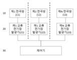
도 1은 본 발명의 일 실시예에 따른 회전하는 교류 전기장을 이용한 전기장 인가 장치의 구성도이다.
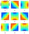
도 2는 두 개의 전극쌍에 소정 주기의 전류를 90도 위상 차이가 나도록 각각 흘려줄 때 시간에 따라 바디 내부로 전달되는 교류 전기장의 방향과 크기를 도시하는 도면이다.
도 3은 본 발명의 일 실시예에 따른 회전하는 교류 전기장을 이용한 전기장 인가 장치에 포함된 교류 전기장 발생기의 일 구현예를 도시하는 도면이다.
도 4는 본 발명의 다른 실시예에 따른 회전하는 교류 전기장을 이용한 전기장 인가 방법의 흐름도이다.1 is a block diagram of an electric field applying device using a rotating AC electric field according to an embodiment of the present invention.
FIG. 2 is a diagram showing the direction and magnitude of an alternating electric field transmitted to the inside of a body over time when a current of a predetermined period is passed through two electrode pairs with a phase difference of 90 degrees.
3 is a diagram illustrating an implementation example of an AC field generator included in an electric field applying device using a rotating AC field according to an embodiment of the present invention.
4 is a flowchart of a method of applying an electric field using a rotating AC electric field according to another embodiment of the present invention.
이하, 첨부된 도면을 참조하여 본 발명이 속하는 기술분야에서 통상의 지식을 가진 자가 본 발명을 용이하게 실시할 수 있도록 바람직한 실시예를 상세히 설명한다. 다만, 본 발명의 바람직한 실시예를 상세하게 설명함에 있어, 관련된 공지 기능 또는 구성에 대한 구체적인 설명이 본 발명의 요지를 불필요하게 흐릴 수 있다고 판단되는 경우에는 그 상세한 설명을 생략한다. 또한, 유사한 기능 및 작용을 하는 부분에 대해서는 도면 전체에 걸쳐 동일한 부호를 사용한다.Hereinafter, preferred embodiments will be described in detail so that those skilled in the art can easily practice the present invention with reference to the accompanying drawings. However, in describing a preferred embodiment of the present invention in detail, if it is determined that a detailed description of a related known function or configuration may unnecessarily obscure the gist of the present invention, the detailed description will be omitted. In addition, the same reference numerals are used throughout the drawings for parts having similar functions and actions.
덧붙여, 명세서 전체에서, 어떤 부분이 다른 부분과 '연결'되어 있다고 할 때, 이는 '직접적으로 연결'되어 있는 경우뿐만 아니라, 그 중간에 다른 소자를 사이에 두고 '간접적으로 연결'되어 있는 경우도 포함한다. 또한, 어떤 구성요소를 '포함'한다는 것은, 특별히 반대되는 기재가 없는 한 다른 구성요소를 제외하는 것이 아니라 다른 구성요소를 더 포함할 수 있다는 것을 의미한다.In addition, throughout the specification, when a part is said to be 'connected' to another part, this is not only the case where it is 'directly connected', but also the case where it is 'indirectly connected' with another element in between. include In addition, 'including' a certain component means that other components may be further included, rather than excluding other components unless otherwise stated.
상술한 바와 같이 본 발명에서는 i) 임의적인 암세포의 분열의 축과 전기장의 방향 사이에서 발생 가능한 무효 각도를 원천적으로 배제하고 ii) 각 방향에서의 전기장의 세기를 일정하게 최대가 되도록 하여 치료 효과를 극대화하기 위한 전기장 인가 장치 및 방법을 제안한다.As described above, in the present invention, i) fundamentally excludes an invalid angle that can occur between the axis of arbitrary cancer cell division and the direction of the electric field, and ii) maximizes the intensity of the electric field in each direction to achieve a therapeutic effect. We propose an electric field application device and method for maximizing
도 1은 본 발명의 일 실시예에 따른 회전하는 교류 전기장을 이용한 전기장 인가 장치의 구성도이다.1 is a block diagram of an electric field applying device using a rotating AC electric field according to an embodiment of the present invention.
도 1을 참조하면, 본 발명의 일 실시예에 따른 회전하는 교류 전기장을 이용한 전기장 인가 장치는 복수의 전극쌍(10), 복수의 교류 전기장 발생기(20) 및 제어기(30)를 포함하여 구성될 수 있다.Referring to FIG. 1 , an electric field applying device using a rotating AC electric field according to an embodiment of the present invention may include a plurality of electrode pairs 10, a plurality of AC
복수의 전극쌍(10)은 체내의 타겟 영역(예를 들어, 암세포, 종양 세포)에 교류 전기장을 전달하기 위한 것으로, 각각의 전극쌍(11, 12, 13)에 의해 타겟 영역에 가해지는 전기장 방향 사이의 각도가 기 설정된 각도 범위에 포함되도록 신체의 타겟 영역에 상응하는 부위에 배치될 수 있다.The plurality of electrode pairs 10 are for delivering an alternating electric field to a target region (eg, cancer cell, tumor cell) in the body, and the electric field applied to the target region by each
일 실시예에 따라, 전기장 인가 장치가 제1 전극쌍(11) 및 제2 전극쌍(12)를 포함하는 경우, 제1 전극쌍(11)에 의해 제1 교류 전기장이 제1 방향으로 타겟 영역에 인가되고, 제2 전극쌍(12)에 의해 제2 교류 전기장이 제2 방향으로 타겟 영역에 인가될 수 있다.According to an embodiment, when the electric field applying device includes the
이 경우, 제1 방향과 제2 방향이 이루는 각도는 60도 내지 90도 범위에 포함될 수 있으며, 바람직하게는 제1 방향과 제2 방향이 서로 직각을 이룰 수 있다.In this case, the angle formed by the first direction and the second direction may be included in the range of 60 degrees to 90 degrees, and preferably, the first direction and the second direction may form a right angle to each other.
또한, 제1 교류 전기장은 제1 주파수와 제1 엔벨로프를 가지고, 제2 교류 전기장은 제2 주파수와 제2 엔벨로프를 가질 수 있다.Also, the first AC electric field may have a first frequency and a first envelope, and the second AC electric field may have a second frequency and a second envelope.
여기서, 제1 주파수 및 제2 주파수는 타겟 영역의 세포의 유사 분열을 방해하도록 선택될 수 있으며, 예를 들어 50kHz 내지 500kHz 범위에서 선택될 수 있다.Here, the first frequency and the second frequency may be selected to disrupt mitotic division of cells in the target region, and may be selected from, for example, a range of 50 kHz to 500 kHz.
또한, 제1 엔벨로프 및 제2 엔벨로프는 타겟 영역의 세포에 전달되는 전기장의 방향이 회전하도록 위상 및 세기가 선택될 수 있다. 이 경우, 회전하는 전기장의 회전 주기가 0.1 초 이상이 되도록 선택될 수 있다. 또한, 제1 엔벨로프와 제2 엔벨로프의 위상 차는 60도 내지 120도 범위에 포함될 수 있으며, 바람직하게는 위상 차는 90도일 수 있다.In addition, phases and intensities of the first envelope and the second envelope may be selected such that the direction of the electric field delivered to the cells of the target region rotates. In this case, the rotation period of the rotating electric field may be selected to be 0.1 second or more. In addition, the phase difference between the first envelope and the second envelope may be included in the range of 60 degrees to 120 degrees, and preferably, the phase difference may be 90 degrees.
복수의 교류 전기장 발생기(20)는 복수의 전극쌍(10)에 인가할 교류 전기장을 발생하기 위한 것으로, 각각의 교류 전기장 발생기(21, 22, 23)가 각각의 전극쌍(11, 12, 13)에 연결될 수 있다.The plurality of AC
여기서, 각각의 교류 전기장 발생기(21, 22, 23)는 전기적으로 독립적으로 전류가 흐르도록 구성, 즉, 부동 접지(floating ground)를 가져야 하고, 서로 절연(isolation)되어 있어야 한다.Here, each of the alternating current field generators 21, 22, and 23 is electrically configured to flow independently, that is, must have a floating ground, and must be isolated from each other.
또한, 각각의 교류 전기장 발생기(21, 22, 23)는 이에 연결된 각각의 전극쌍(11, 12, 13)에 동시에 교류 전류를 인가하여 복수의 교류 전기장이 동시에 전달되도록 하고, 복수의 교류 전기장에 의해 형성되어 타겟 영역에 전달되는 전기장의 방향이 시간에 따라 회전하도록 할 수 있다.In addition, each of the AC electric field generators 21, 22, and 23 simultaneously applies an AC current to each of the electrode pairs 11, 12, and 13 connected thereto so that a plurality of AC electric fields are simultaneously transmitted, and the plurality of AC electric fields The direction of the electric field formed by and transmitted to the target area may be rotated with time.
제어기(30)는 각각의 교류 전기장 발생기(21, 22, 23)에 의한 교류 전기장 발생을 제어하여 타겟 영역에 전달되는 전기장의 방향이 시간에 따라 회전하도록 하기 위한 것이다.The
일 실시예에 따르면, 직교하는 두 개의 전극쌍에 의해 체내의 타겟 영역 내의 암세포에 하기의 수학식 1 및 2와 같은 교류 전기장 E1과 E2를 동시에 전달할 수 있다.According to an embodiment, alternating electric fields E1 and E2 as shown in


여기서, ω는 유전영동 현상에 의한 세포사를 유도하는 최적 주파수를 의미하는 것으로, 50kHz 내지 500kHz이다. 또한, A1(t)와 A2(t)는 각각 교류 전기장 E1과 E2의 엔벨로프 세기를 의미한다.Here, ω means the optimum frequency for inducing cell death by dielectrophoresis, and is 50 kHz to 500 kHz. In addition, A1 (t) and A2 (t) denote envelope strengths of AC electric fields E1 and E2 , respectively.
이 경우, 두 개의 전극쌍에 의해 암세포에 전달되는 전기장은 교류 전기장 E1과 E2의 벡터 합이 된다.In this case, the electric field delivered to the cancer cell by the two electrode pairs becomes the vector sum of the alternating electric fields E1 and E2 .
또한, 두 전기장이 직교 방향으로 전달되는 경우, 전기장의 세기를 일정하게 유지하기 위해서는 A1(t)와 A2(t)가 하기의 수학식 3의 관계를 만족하여야 한다. 따라서, A1(t)와 A2(t)는 각각 수학식 4와 5를 만족한다. 여기서, Tenv은 엔벨로프의 주기를 의미하고, Ø는 A1(t)와 A2(t)의 위상 차이(phase shift)를 의미한다. 또한, A0는 암세포에 전달되는 전기장의 세기를 의미한다.In addition, when two electric fields are transmitted in an orthogonal direction, in order to maintain a constant electric field strength, A1 (t) and A2 (t) must satisfy the relationship of Equation 3 below. Therefore, A1 (t) and A2 (t) satisfy Equations 4 and 5, respectively. Here, Tenv means the period of the envelope, and Ø means the phase shift between A1 (t) and A2 (t). Also, A0 means the strength of an electric field delivered to cancer cells.


다른 실시예에 따르면, 3차원 공간에서 서로 직교하는 세 개의 전극쌍에 의해 타겟 영역에 교류 전기장을 동시에 전달하여 3차원 공간에서 전기장이 회전하도록 할 수도 있다.According to another embodiment, an alternating current electric field may be simultaneously delivered to a target region by three electrode pairs orthogonal to each other in a 3D space so that the electric field rotates in the 3D space.
이 경우, 각 전극쌍에 인가되는 교류 전기장의 엔벨로프는 하기의 수학식 6 내지 9를 만족하여야 한다.In this case, the envelope of the alternating electric field applied to each electrode pair must satisfy Equations 6 to 9 below.


여기서, θ 및 φ는 각각 θ ∈ [0, π], φ ∈ [0, 2π)의 범위에 들어오는 시간의 함수이다.Here, θ and φ are functions of time that fall within the ranges of θ ∈ [0, π] andφ ∈ [0, 2π), respectively.
도 2는 두 개의 전극쌍에 소정 주기의 전류를 90도 위상 차이가 나도록 각각 흘려줄 때 시간에 따라 바디 내부로 전달되는 교류 전기장의 방향과 크기를 도시하는 도면이다.FIG. 2 is a diagram showing the direction and magnitude of an alternating electric field transmitted to the inside of a body over time when a current of a predetermined period is passed through two electrode pairs with a phase difference of 90 degrees.
일 실시예에 따라, 바디(105)에 부착된 두 개의 전극쌍(101 및 102, 103 및 104)에 엔벨로프의 주기(Tenv)가 240초인 엔벨로프 전류를 90도 위상 차이가 나도록 각각 흘려줄 수 있다. 이 경우, 바디(105) 내부에 전달되는 교류 전기장의 방향과 크기를 시간에 따라 시뮬레이션한 결과를 나타내면 도 2와 같다.According to one embodiment, an envelope current having an envelope period (Tenv ) of 240 seconds is applied to the two
구체적으로, 도 2의 (a) 내지 (i)는 각각 엔벨로프의 주기 동안 30초 간격으로, 즉 0, 30, 60, 90, 120, 150, 180, 210, 240초에서의 바디(105)의 내부 전기장을 도시한 것이다.Specifically, (a) to (i) of FIG. 2 show the
도 2를 참조하면, 상술한 바와 같이 두 개의 전극쌍에 소정 주기의 전류를 90도 위상 차이가 나도록 각각 흘려줄 때, 시간에 따라 일정한 크기의 전기장이 회전함을 알 수 있다.Referring to FIG. 2 , it can be seen that, as described above, when a current of a predetermined period is passed through each of the two electrode pairs with a phase difference of 90 degrees, an electric field of a constant size rotates with time.
도 3은 본 발명의 일 실시예에 따른 회전하는 교류 전기장을 이용한 전기장 인가 장치에 포함된 교류 전기장 발생기의 일 구현예를 도시하는 도면으로, 교류 전기장 발생기는 폐회로(cloased-loop) 피드백 시스템을 구성하도록 구현될 수 있다.3 is a diagram showing an implementation example of an AC field generator included in an electric field applying device using a rotating AC field according to an embodiment of the present invention, and the AC field generator constitutes a closed-loop feedback system. can be implemented to
구체적으로, 각각의 교류 전기장 발생기의 입력신호(201A, 201B)로는 하기의 수학식 10 및 11과 같은 전류가 입력될 수 있다. 즉, 각각의 교류 전기장 발생기의 입력신호는 수학식 4 및 5와 같은 엔벨로프를 가지는 전류일 수 있다.Specifically, currents as shown in


이와 같은 입력신호(201A, 201B)와 피드백 신호(208A, 208B)의 차이가 제어 앰프(Control amp)(203A, 203B)를 통해 출력될 수 있다.The difference between the input signals 201A and 201B and the feedback signals 208A and 208B may be output through
이 경우, 전체 폐회로 피드백 시스템의 밴드위스(bandwidth)는 피드백 캐패시터(Feedback capacitor)(204A, 204B)에 의해 제어될 수 있다.In this case, the bandwidth of the entire closed-loop feedback system may be controlled by
제어 앰프(203A, 203B)의 출력단은 파워 앰프(Power amp)(205A, 205B)를 구성하는 내부 FET의 Gate 신호로 연결되어 파워 앰프(205A, 205B)로 입력되는 파워 소스의 크기를 제어할 수 있다.The output stage of the
파워 앰프(205A, 205B)의 출력단은 각각의 전극쌍(Electrode 1, Electrode 2)에 연결되어 인체 내에 전기장을 전달한다.Output terminals of the
한편, 각 전극에 흐르는 전류는 센싱 저항(Sensing resistor)(206A, 206B) 양단에 걸리는 전압에 비례하고, 이 전압은 전류/전압 변환기(I/E Converter)(207A, 207B)에 의해 피드백 신호(Feedback signal)(208A, 208B)로 변환되어 가산기(Adder circuit)(202A, 202B)를 통해 다시 제어 앰프(203A, 203B)로 입력된다.On the other hand, the current flowing through each electrode is proportional to the voltage across the sensing resistors (206A, 206B), and this voltage is converted into a feedback signal (I/E Converter) (207A, 207B). Feedback signal) (208A, 208B) and input back to the control amplifier (203A, 203B) through the adder (Adder circuit) (202A, 202B).
또한, 파워 앰프(205A, 205B)로 입력되는 파워 소스는 서로 절연(isolation)되어 있어야 하며, 각각의 신호 접지(Signal ground)(209A, 209B)는 부동 접지로 구성된다.In addition, power sources input to the
도 4는 본 발명의 다른 실시예에 따른 회전하는 교류 전기장을 이용한 전기장 인가 방법의 흐름도로, 두 개의 전극쌍을 이용하여 교류 전기장이 회전하도록 하여 전기장 인가를 수행하는 방법에 대해 설명한다.4 is a flowchart of a method of applying an electric field using a rotating AC electric field according to another embodiment of the present invention, and describes a method of applying an electric field by rotating an AC electric field using two electrode pairs.
도 4를 참조하면, 우선 제1 교류 전기장의 주파수 및 엔벨로프를 선택하고(S41), 제2 교류 전기장의 주파수 및 엔벨로프를 선택할 수 있다(S42). 여기서, 제1 교류 전기장 및 제2 교류 전기장의 주파수는 타겟 영역의 세포의 유사 분열을 방해하도록 형성되고, 제1 교류 전기장 및 제2 교류 전기장의 엔벨로프는 타겟 영역의 세포에 전달되는 전기장의 방향이 회전하도록 위상 및 진폭이 선택될 수 있다.Referring to FIG. 4 , first, the frequency and envelope of the first AC electric field may be selected (S41), and the frequency and envelope of the second AC electric field may be selected (S42). Here, the frequencies of the first AC electric field and the second AC electric field are formed to disrupt mitotic division of cells in the target region, and the envelopes of the first AC electric field and the second AC electric field are the direction of the electric field transmitted to the cells in the target region. The phase and amplitude can be selected to rotate.
이후, 제1 전극쌍 및 제2 전극쌍에 의해 각각 제1 교류 전기장 및 제2 교류 전기장을 동시에 인가할 수 있으며(S43-1, S43-2), 제1 교류 전기장 및 제2 교류 전기장에 의해 타겟 영역에 전달되는 전기장이 회전하도록 하여 전기장 치료를 수행할 수 있다(S44).Then, the first AC electric field and the second AC electric field may be simultaneously applied by the first electrode pair and the second electrode pair (S43-1, S43-2), respectively, and the first AC electric field and the second AC electric field The electric field treatment may be performed by rotating the electric field delivered to the target region (S44).
도 4를 참조하여 상술한 전기장 인가 방법은 도 1을 참조하여 상술한 전기장 인가 장치에 의해 수행될 수 있으며, 각 단계에 대한 구체적인 방법은 도 1 내지 도 3을 참조하여 상술한 바와 동일하므로 이에 대한 중복적인 설명은 생략한다.The electric field application method described above with reference to FIG. 4 may be performed by the electric field application device described above with reference to FIG. 1, and the specific method for each step is the same as that described with reference to FIGS. 1 to 3. Redundant descriptions are omitted.
본 발명은 전술한 실시예 및 첨부된 도면에 의해 한정되는 것이 아니다. 본 발명이 속하는 기술분야에서 통상의 지식을 가진 자에게 있어, 본 발명의 기술적 사상을 벗어나지 않는 범위 내에서 본 발명에 따른 구성요소를 치환, 변형 및 변경할 수 있다는 것이 명백할 것이다.The present invention is not limited by the foregoing embodiments and accompanying drawings. It will be clear to those skilled in the art that the components according to the present invention can be substituted, modified, and changed without departing from the technical spirit of the present invention.
10, 11, 12, 13: 전극쌍
20, 21, 22, 23: 교류 전기장 발생기
30: 제어기
101, 102: 제1 전극쌍
103, 104: 제2 전극쌍
105: 바디
201: 입력 신호
202: 가산기
203: 제어 앰프
204: 피드백 캐패시터
205: 파워 앰프
206: 센싱 저항
207: 전류/전압 변환기
208: 피드백 전압 신호
209: 신호 접지10, 11, 12, 13: electrode pair
20, 21, 22, 23: AC electric field generator
30: controller
101, 102: first electrode pair
103, 104: second electrode pair
105: body
201: input signal
202: adder
203: control amplifier
204: feedback capacitor
205: power amplifier
206: sensing resistance
207: current/voltage converter
208: feedback voltage signal
209 signal ground
Claims (9)
Translated fromKorean상기 복수의 전극쌍에 각각 연결되며, 상기 복수의 전극쌍에 인가할 교류 전기장을 발생하는 복수의 교류 전기장 발생기; 및
상기 복수의 교류 전기장 발생기에 의한 교류 전기장 발생을 제어하는 제어기를 포함하고,
각각의 교류 전기장 발생기는 이에 연결된 각각의 전극쌍에 동시에 교류 전류를 인가하여 복수의 교류 전기장이 동시에 전달되도록 하고,
상기 복수의 전극쌍은 제1 전극쌍 및 제2 전극쌍을 포함하고,
상기 제1 전극쌍에 의해 제1 교류 전기장이 제1 방향으로 타겟 영역에 인가되고, 상기 제2 전극쌍에 의해 제2 교류 전기장이 제2 방향으로 타겟 영역에 인가되며,
상기 제1 교류 전기장은 제1 주파수와 제1 엔벨로프를 가지고, 상기 제2 교류 전기장은 제2 주파수와 제2 엔벨로프를 가지며,
상기 제1 주파수 및 제2 주파수는 상기 타겟 영역의 세포의 유사 분열을 방해하도록 50kHz 내지 500kHz 범위에서 선택되고,
상기 제1 엔벨로프 및 제2 엔벨로프는 상기 타겟 영역의 세포에 전달되는 전기장의 방향이 회전하도록 위상 및 세기가 선택되는 것을 특징으로 하는 회전하는 교류 전기장을 이용한 전기장 인가 장치.
a plurality of electrode pairs that deliver an alternating electric field to a target region in the body;
a plurality of alternating current electric field generators respectively connected to the plurality of electrode pairs and generating an alternating current electric field to be applied to the plurality of electrode pairs; and
A controller for controlling the generation of AC electric fields by the plurality of AC electric field generators;
Each AC electric field generator simultaneously applies an AC current to each electrode pair connected thereto so that a plurality of AC electric fields are simultaneously transmitted,
The plurality of electrode pairs include a first electrode pair and a second electrode pair,
A first AC electric field is applied to a target region in a first direction by the first electrode pair, and a second AC electric field is applied to a target region by the second electrode pair in a second direction;
The first AC electric field has a first frequency and a first envelope, and the second AC electric field has a second frequency and a second envelope;
The first frequency and the second frequency are selected in the range of 50 kHz to 500 kHz to disrupt mitosis of cells in the target region,
The electric field applying device using a rotating AC electric field, characterized in that the phase and intensity of the first envelope and the second envelope are selected so that the direction of the electric field transmitted to the cells of the target region rotates.
상기 복수의 전극쌍은, 상기 복수의 전극쌍 각각에 의해 상기 타겟 영역에 가해지는 전기장 방향 사이의 각도가 기 설정된 각도 범위에 포함되도록 상기 타겟 영역에 상응하는 부위에 배치되는 것을 특징으로 하는 회전하는 교류 전기장을 이용한 전기장 인가 장치.
According to claim 1,
The plurality of electrode pairs are rotated, characterized in that disposed in a portion corresponding to the target area such that an angle between directions of an electric field applied to the target area by each of the plurality of electrode pairs is included in a predetermined angular range An electric field applying device using an alternating electric field.
상기 제1 엔벨로프와 제2 엔벨로프의 위상 차는 60도 내지 120도 범위에 포함되는 것을 특징으로 하는 회전하는 교류 전기장을 이용한 전기장 인가 장치.
According to claim 1,
The electric field applying device using a rotating AC electric field, characterized in that the phase difference between the first envelope and the second envelope is included in the range of 60 degrees to 120 degrees.
상기 제1 방향과 제2 방향이 이루는 각도는 90도이고,
상기 제1 엔벨로프와 제2 엔벨로프의 세기는 각각 하기의 수학식,


과 같으며, A1 및 A2는 각각 제1 엔벨로프 및 제2 엔벨로프의 세기이고,
Tenv은 엔벨로프의 주기이고,
는 A1와 A2의 위상 차인 것을 특징으로 하는 회전하는 교류 전기장을 이용한 전기장 인가 장치.
According to claim 1,
The angle formed by the first direction and the second direction is 90 degrees,
The intensities of the first envelope and the second envelope are each expressed by the following equations,
, where A1 and A2 are the intensities of the first and second envelopes, respectively,
Tenv is the period of the envelope,
is A1 and A2 An electric field application device using a rotating AC electric field, characterized in that the phase difference.
상기 회전하는 전기장의 회전 주기가 0.1 초 이상인 것을 특징으로 하는 회전하는 교류 전기장을 이용한 전기장 인가 장치.
According to claim 1,
An electric field application device using a rotating alternating current electric field, characterized in that the rotation period of the rotating electric field is 0.1 second or more.
상기 각각의 교류 전기장 발생기는 전기적으로 독립적으로 전류가 흐르도록 부동 접지(floating ground)를 가지고, 서로 절연(isolation)되는 것을 특징으로 하는 회전하는 교류 전기장을 이용한 전기장 인가 장치.
According to claim 1,
The electric field application device using a rotating AC electric field, characterized in that each AC electric field generator has a floating ground so that current flows electrically independently and is isolated from each other.
제2 전극쌍에 의해 상기 타겟 영역에 전달할 제2 교류 전기장의 주파수 및 엔벨로프를 선택하는 단계;
상기 제1 전극쌍 및 제2 전극쌍에 의해 각각 제1 교류 전기장 및 제2 교류 전기장을 동시에 인가하는 단계; 및
상기 제1 교류 전기장 및 제2 교류 전기장에 의해 상기 타겟 영역에 전달되는 전기장이 회전하는 단계를 포함하며,
상기 제1 교류 전기장은 제1 주파수와 제1 엔벨로프를 가지고, 상기 제2 교류 전기장은 제2 주파수와 제2 엔벨로프를 가지며,
상기 제1 주파수 및 제2 주파수는 상기 타겟 영역의 세포의 유사 분열을 방해하도록 50kHz 내지 500kHz 범위에서 선택되고,
상기 제1 엔벨로프 및 제2 엔벨로프는 상기 타겟 영역의 세포에 전달되는 전기장의 방향이 회전하도록 위상 및 세기가 선택되는 것을 특징으로 하는, 회전하는 교류 전기장을 이용한 전기장 인가 방법.
selecting a frequency and an envelope of the first AC electric field to be delivered to the target region in the body by the first electrode pair;
selecting a frequency and an envelope of a second AC electric field to be transmitted to the target area by a second electrode pair;
simultaneously applying a first alternating current electric field and a second alternating current electric field by the first electrode pair and the second electrode pair, respectively; and
Rotating an electric field transmitted to the target region by the first AC electric field and the second AC electric field,
The first AC electric field has a first frequency and a first envelope, and the second AC electric field has a second frequency and a second envelope;
The first frequency and the second frequency are selected in the range of 50 kHz to 500 kHz to disrupt mitosis of cells in the target region,
Wherein the phase and intensity of the first envelope and the second envelope are selected such that a direction of the electric field transmitted to the cells of the target region rotates.
Priority Applications (3)
| Application Number | Priority Date | Filing Date | Title |
|---|---|---|---|
| KR1020200160333AKR102519139B1 (en) | 2020-11-25 | 2020-11-25 | Apparatus and Method for Electric Field Therapy using Rotating Electric Fields |
| PCT/KR2021/000061WO2022114383A1 (en) | 2020-11-25 | 2021-01-05 | Electric field cancer treatment apparatus and method using rotating alternating current electric field |
| US18/038,708US11975211B2 (en) | 2020-11-25 | 2021-01-05 | Electric field cancer treatment apparatus and method using rotating alternating current electric field |
Applications Claiming Priority (1)
| Application Number | Priority Date | Filing Date | Title |
|---|---|---|---|
| KR1020200160333AKR102519139B1 (en) | 2020-11-25 | 2020-11-25 | Apparatus and Method for Electric Field Therapy using Rotating Electric Fields |
Publications (2)
| Publication Number | Publication Date |
|---|---|
| KR20220072573A KR20220072573A (en) | 2022-06-02 |
| KR102519139B1true KR102519139B1 (en) | 2023-04-25 |
Family
ID=81754533
Family Applications (1)
| Application Number | Title | Priority Date | Filing Date |
|---|---|---|---|
| KR1020200160333AActiveKR102519139B1 (en) | 2020-11-25 | 2020-11-25 | Apparatus and Method for Electric Field Therapy using Rotating Electric Fields |
Country Status (3)
| Country | Link |
|---|---|
| US (1) | US11975211B2 (en) |
| KR (1) | KR102519139B1 (en) |
| WO (1) | WO2022114383A1 (en) |
Families Citing this family (6)
| Publication number | Priority date | Publication date | Assignee | Title |
|---|---|---|---|---|
| US20220241603A1 (en)* | 2021-02-03 | 2022-08-04 | Novocure Gmbh | Varying Parameters of Tumor Treating Fields (TTFields) Treatment to Overcome Treatment Resistance |
| WO2024106837A1 (en)* | 2022-11-17 | 2024-05-23 | 주식회사 필드큐어 | Electrode array for impedance compensation |
| CN116269733B (en)* | 2023-03-20 | 2024-05-03 | 成都飞云科技有限公司 | Pulse ablation catheter, device and pulse ablation method |
| KR20240149471A (en) | 2023-04-05 | 2024-10-15 | 주식회사 뉴아인 | Electric field focusing device for apoptosis |
| KR20240149472A (en) | 2023-04-05 | 2024-10-15 | 주식회사 뉴아인 | Electric field focusing device for apoptosis |
| KR20240149470A (en) | 2023-04-05 | 2024-10-15 | 주식회사 뉴아인 | Apparartus of apoptosis using electric field |
Citations (3)
| Publication number | Priority date | Publication date | Assignee | Title |
|---|---|---|---|---|
| JP2007117975A (en) | 2005-10-24 | 2007-05-17 | Inoue Satomi | Small general-purpose rotary impact crusher |
| US20110137229A1 (en)* | 2000-02-17 | 2011-06-09 | Yoram Palti | Treating bacteria with electric fields |
| US20190117975A1 (en)* | 2014-10-08 | 2019-04-25 | Massachusetts Institute Of Technology | Methods and Apparatus for Stimulation of Biological Tissue |
Family Cites Families (10)
| Publication number | Priority date | Publication date | Assignee | Title |
|---|---|---|---|---|
| CN1976738B (en) | 2004-04-23 | 2010-09-01 | 诺沃库勒有限公司 | Treating a tumor or the like with an electric field |
| CN112402798B (en) | 2005-10-03 | 2021-11-16 | 诺沃库勒有限责任公司 | Optimizing electric field characteristics to increase the effect of an electric field on proliferating cells |
| JP4751226B2 (en) | 2006-03-30 | 2011-08-17 | 株式会社東芝 | Image display element unit |
| US20090076500A1 (en) | 2007-09-14 | 2009-03-19 | Lazure Technologies, Llc | Multi-tine probe and treatment by activation of opposing tines |
| US9655669B2 (en) | 2013-05-06 | 2017-05-23 | Novocure Limited | Optimizing treatment using TTFields by changing the frequency during the course of long term tumor treatment |
| AU2015300886B2 (en) | 2014-08-06 | 2019-10-31 | Nero Tronik Ip Holding (Jersey) Limited | Electrodes and electrode positioning systems for transvascular neuromodulation |
| US10821283B2 (en) | 2016-04-04 | 2020-11-03 | Novocure Gmbh | Reducing motility of cancer cells using tumor treating fields (TTFields) |
| EP4454697A3 (en) | 2016-06-30 | 2024-12-25 | Novocure GmbH | Arrays for longitudinal delivery of ttfields to a body |
| CN113727753B (en)* | 2019-04-22 | 2024-09-13 | 波士顿科学国际有限公司 | Electrical stimulation devices for cancer treatment |
| KR20220055065A (en)* | 2020-10-26 | 2022-05-03 | 주식회사 뉴아인 | Device that induces destroying cells on abnormally dividing cells and the driving method thereof |
- 2020
- 2020-11-25KRKR1020200160333Apatent/KR102519139B1/enactiveActive
- 2021
- 2021-01-05USUS18/038,708patent/US11975211B2/enactiveActive
- 2021-01-05WOPCT/KR2021/000061patent/WO2022114383A1/ennot_activeCeased
Patent Citations (3)
| Publication number | Priority date | Publication date | Assignee | Title |
|---|---|---|---|---|
| US20110137229A1 (en)* | 2000-02-17 | 2011-06-09 | Yoram Palti | Treating bacteria with electric fields |
| JP2007117975A (en) | 2005-10-24 | 2007-05-17 | Inoue Satomi | Small general-purpose rotary impact crusher |
| US20190117975A1 (en)* | 2014-10-08 | 2019-04-25 | Massachusetts Institute Of Technology | Methods and Apparatus for Stimulation of Biological Tissue |
Also Published As
| Publication number | Publication date |
|---|---|
| KR20220072573A (en) | 2022-06-02 |
| US20230398366A1 (en) | 2023-12-14 |
| US11975211B2 (en) | 2024-05-07 |
| WO2022114383A1 (en) | 2022-06-02 |
Similar Documents
| Publication | Publication Date | Title |
|---|---|---|
| KR102519139B1 (en) | Apparatus and Method for Electric Field Therapy using Rotating Electric Fields | |
| JP5559460B2 (en) | Method for treating tumors or the like using electric fields of different orientations | |
| US7519420B2 (en) | Apparatus for selectively destroying dividing cells | |
| DK2281602T3 (en) | Apparatus for treating a tumor with an electric field | |
| US4346715A (en) | Hyperthermia heating apparatus | |
| JP4750784B2 (en) | Treatment of tumors by electric fields of different frequencies | |
| US11911098B2 (en) | Apparatus for treating tumors by evanescent waves | |
| CN113616922B (en) | Target electric field generating device and control method | |
| Milestone et al. | Sinusoidal RF simulations for optimized electroporation protocols | |
| CN111465427B (en) | Device for stimulating skin regeneration | |
| CN118647434A (en) | High frequency electrotherapy device with two channels connected in series or in parallel | |
| López-Alonso et al. | Optimizing IRE targeting using multi-electrode structure and biomedical multi-output generator | |
| Abed et al. | Ion channels as molecular targets of glioblastoma electrotherapy | |
| US20240325768A1 (en) | Reducing Electrosensation When Treating a Subject Using a Rotating Alternating Electric Field by Gradually Increasing the Amplitude of the Field | |
| KR101861963B1 (en) | Method for stimulating, and apparatuses performing the same | |
| JP2003245365A (en) | Destroying apparatus for aids tissue and articular rheumatism by micro-electromagnetic wave | |
| HK40030557A (en) | Apparatus for treating a tumor by an electric field | |
| Wedlick | CHANGING TRENDS IN MEDICAL ELECTRICITY |
Legal Events
| Date | Code | Title | Description |
|---|---|---|---|
| PA0109 | Patent application | St.27 status event code:A-0-1-A10-A12-nap-PA0109 | |
| PA0201 | Request for examination | St.27 status event code:A-1-2-D10-D11-exm-PA0201 | |
| P11-X000 | Amendment of application requested | St.27 status event code:A-2-2-P10-P11-nap-X000 | |
| P13-X000 | Application amended | St.27 status event code:A-2-2-P10-P13-nap-X000 | |
| PG1501 | Laying open of application | St.27 status event code:A-1-1-Q10-Q12-nap-PG1501 | |
| E902 | Notification of reason for refusal | ||
| PE0902 | Notice of grounds for rejection | St.27 status event code:A-1-2-D10-D21-exm-PE0902 | |
| E13-X000 | Pre-grant limitation requested | St.27 status event code:A-2-3-E10-E13-lim-X000 | |
| P11-X000 | Amendment of application requested | St.27 status event code:A-2-2-P10-P11-nap-X000 | |
| P13-X000 | Application amended | St.27 status event code:A-2-2-P10-P13-nap-X000 | |
| E701 | Decision to grant or registration of patent right | ||
| PE0701 | Decision of registration | St.27 status event code:A-1-2-D10-D22-exm-PE0701 | |
| PR0701 | Registration of establishment | St.27 status event code:A-2-4-F10-F11-exm-PR0701 | |
| PR1002 | Payment of registration fee | St.27 status event code:A-2-2-U10-U11-oth-PR1002 Fee payment year number:1 | |
| PG1601 | Publication of registration | St.27 status event code:A-4-4-Q10-Q13-nap-PG1601 |