KR102518274B1 - biopsy rotary resection device - Google Patents
biopsy rotary resection deviceDownload PDFInfo
- Publication number
- KR102518274B1 KR102518274B1KR1020207029825AKR20207029825AKR102518274B1KR 102518274 B1KR102518274 B1KR 102518274B1KR 1020207029825 AKR1020207029825 AKR 1020207029825AKR 20207029825 AKR20207029825 AKR 20207029825AKR 102518274 B1KR102518274 B1KR 102518274B1
- Authority
- KR
- South Korea
- Prior art keywords
- pipe
- cavity
- knife pipe
- sealing
- gap
- Prior art date
- Legal status (The legal status is an assumption and is not a legal conclusion. Google has not performed a legal analysis and makes no representation as to the accuracy of the status listed.)
- Active
Links
- 238000001574biopsyMethods0.000titleclaimsabstractdescription32
- 238000002271resectionMethods0.000titleclaimsdescription20
- 238000007789sealingMethods0.000claimsabstractdescription112
- 238000002679ablationMethods0.000claimsabstractdescription23
- 238000009423ventilationMethods0.000claimsdescription26
- 238000009434installationMethods0.000claimsdescription13
- 230000000903blocking effectEffects0.000claimsdescription7
- 238000005070samplingMethods0.000abstractdescription12
- 238000012546transferMethods0.000abstractdescription4
- 238000000034methodMethods0.000description18
- 238000010586diagramMethods0.000description12
- 238000004891communicationMethods0.000description8
- 230000000694effectsEffects0.000description8
- 238000005520cutting processMethods0.000description5
- 206010028980NeoplasmDiseases0.000description3
- 238000004026adhesive bondingMethods0.000description3
- 230000002411adverseEffects0.000description3
- 230000032683agingEffects0.000description3
- 210000000481breastAnatomy0.000description3
- 238000012423maintenanceMethods0.000description3
- 238000001179sorption measurementMethods0.000description3
- 238000009826distributionMethods0.000description2
- 238000012986modificationMethods0.000description2
- 230000004048modificationEffects0.000description2
- 238000003466weldingMethods0.000description2
- 206010039580ScarDiseases0.000description1
- 206010052428WoundDiseases0.000description1
- 208000027418Wounds and injuryDiseases0.000description1
- 230000009286beneficial effectEffects0.000description1
- 201000007295breast benign neoplasmDiseases0.000description1
- 238000003745diagnosisMethods0.000description1
- 230000001815facial effectEffects0.000description1
- 230000035876healingEffects0.000description1
- 230000008520organizationEffects0.000description1
- 238000006467substitution reactionMethods0.000description1
- 238000001356surgical procedureMethods0.000description1
Images


Classifications
- A—HUMAN NECESSITIES
- A61—MEDICAL OR VETERINARY SCIENCE; HYGIENE
- A61B—DIAGNOSIS; SURGERY; IDENTIFICATION
- A61B10/00—Instruments for taking body samples for diagnostic purposes; Other methods or instruments for diagnosis, e.g. for vaccination diagnosis, sex determination or ovulation-period determination; Throat striking implements
- A61B10/02—Instruments for taking cell samples or for biopsy
- A61B10/0233—Pointed or sharp biopsy instruments
- A61B10/0266—Pointed or sharp biopsy instruments means for severing sample
- A61B10/0275—Pointed or sharp biopsy instruments means for severing sample with sample notch, e.g. on the side of inner stylet
- A—HUMAN NECESSITIES
- A61—MEDICAL OR VETERINARY SCIENCE; HYGIENE
- A61B—DIAGNOSIS; SURGERY; IDENTIFICATION
- A61B10/00—Instruments for taking body samples for diagnostic purposes; Other methods or instruments for diagnosis, e.g. for vaccination diagnosis, sex determination or ovulation-period determination; Throat striking implements
- A61B10/02—Instruments for taking cell samples or for biopsy
- A61B10/0233—Pointed or sharp biopsy instruments
- A61B10/0283—Pointed or sharp biopsy instruments with vacuum aspiration, e.g. caused by retractable plunger or by connected syringe
- A—HUMAN NECESSITIES
- A61—MEDICAL OR VETERINARY SCIENCE; HYGIENE
- A61B—DIAGNOSIS; SURGERY; IDENTIFICATION
- A61B10/00—Instruments for taking body samples for diagnostic purposes; Other methods or instruments for diagnosis, e.g. for vaccination diagnosis, sex determination or ovulation-period determination; Throat striking implements
- A61B10/02—Instruments for taking cell samples or for biopsy
- A61B2010/0208—Biopsy devices with actuators, e.g. with triggered spring mechanisms
Landscapes
- Health & Medical Sciences (AREA)
- Life Sciences & Earth Sciences (AREA)
- Medical Informatics (AREA)
- Engineering & Computer Science (AREA)
- Biomedical Technology (AREA)
- Heart & Thoracic Surgery (AREA)
- Pathology (AREA)
- Molecular Biology (AREA)
- Surgery (AREA)
- Animal Behavior & Ethology (AREA)
- General Health & Medical Sciences (AREA)
- Public Health (AREA)
- Veterinary Medicine (AREA)
- Surgical Instruments (AREA)
- Sampling And Sample Adjustment (AREA)
Abstract
Translated fromKoreanDescription
Translated fromKorean본 발명은 의료기기에 관한 것으로, 특히 생검 회전 절제 장치에 관한 것이다.The present invention relates to medical devices, and more particularly to biopsy rotary ablation devices.
생검 회전 절제 장치는 최소 침습적 외과 천자 수술 중에서 널리 사용되는데, 우선, 천자용 칼날을 채택하면 수술 상처를 줄이고, 바늘이 필요 없으며, 치료 요구에 부합될 뿐만 아니라, 외형적인 미관도 확보할 수 있는데, 특히 유방이나 안면부 등의 상처를 줄여 잘 아물고, 남는 흔적이 적고, 손상이 작으며, 빠르게 회복하는 등의 장점이 있으므로, 대다수 여성들로부터 많은 환영을 받고 있다. 진공보조흡인 유방 생검과 회전 절제는 현재 유방 생검 수술에 사용되는 가장 효과적인 방식의 하나로서, 유방에서 의심되는 병소에 대해 중복 절단을 진행하여 유방의 조직 표본을 충분히 확보하는 것으로, 유방암의 조기 발견과 진단에 편리하도록 하고, 동시에 유방 양성 종양의 최소 침습 절제를 진행할 수도 있다.The rotary biopsy device is widely used among minimally invasive surgical puncture operations. First of all, the adoption of a puncture blade reduces surgical scars, eliminates the need for needles, meets treatment needs, and secures external aesthetics. In particular, it has advantages such as reducing wounds on the breast or facial area, healing them well, leaving few traces, minimizing damage, and recovering quickly, so it is welcomed by most women. Vacuum-assisted aspiration breast biopsy and rotational resection are one of the most effective methods currently used in breast biopsy surgery. It is convenient for diagnosis, and at the same time, minimally invasive resection of benign breast tumors can be performed.
회전 절제 장치의 헤드부는 직경이 작은 천자용 헤드를 적용하여 천자하며, 천자용 헤드의 꼬리부와 외부 나이프 파이프 헤드부는 동축으로 고정된다. 외부 나이프 파이프는 동축으로 설치되는 내부 나이프 파이프 외부를 감싼다. 외부 나이프 파이프 헤드부에는 칼날 홈이 있으며, 천자 완료 전에 내부 나이프 파이프 헤드부는 가장 먼 끝단에 위치하고, 천자 완료 후에는 내부 나이프 파이프가 회전하면서 후진하고, 칼날 홈이 열리고, 이와 동시에 음압 시스템이 종양 조직을 칼날 홈으로 흡입한다. 내부 나이프 파이프 헤드부에는 내부 챔퍼(Chamfer) 칼날이 있으며, 조직 흡착 완료 후에는 내부 나이프 파이프가 회전하면서 전진하고, 조직에 대해 회전 절제를 진행하며, 절제된 조직은 음압에 의해 내부 나이프 파이프의 안쪽 체임버를 거쳐 회전 절제 장치 꼬리부의 샘플 수집 용기로 흡입된다.The head of the rotary ablation device performs puncture by applying a puncture head having a small diameter, and the tail of the puncture head and the external knife pipe head are coaxially fixed. The outer knife pipe wraps around the outside of the coaxially installed inner knife pipe. The outer knife pipe head has a blade groove, the inner knife pipe head is located at the farthest end before puncture is completed, and after puncture is completed, the inner knife pipe rotates and moves backward, the blade groove opens, and at the same time the negative pressure system is applied to the tumor tissue into the groove of the blade. There is an internal chamfer blade in the head of the internal knife pipe, and after tissue adsorption is completed, the internal knife pipe rotates and advances, and rotational ablation is performed on the tissue, and the ablated tissue is moved into the inner chamber of the internal knife pipe by negative pressure. After passing through, it is sucked into the sample collection container at the tail of the rotary ablation device.
회전 절제 장치는 주로 음압 시스템을 통해 잘라 낸 종양 조직을 흡입하여 인출하거나, 칼날 홈과 시스템 사이의 압력차를 이용하여 조직을 샘플 수집 용기로 운송하는 것으로 이해할 수 있다. 하지만 한 번의 흡착 절제 작업이 완료된 후, 칼날 홈 주위의 압력 강도가 내부 나이프 파이프 내의 압력 강도와 같아서 전제 칼 세트가 등압 상태에 놓이며, 흡착 제거된 조직이 칼날 홈에서 샘플 수집기로 흘러가기가 쉽지 않으므로 샘플링 효과가 좋지 않다는 문제점이 있다.It can be understood that the rotational ablation device mainly sucks and withdraws the cut tumor tissue through a negative pressure system, or transfers the tissue to a sample collection container by using a pressure difference between the blade groove and the system. However, after one suction ablation operation is completed, the pressure intensity around the blade groove is equal to the pressure intensity in the inner knife pipe, so that the entire knife set is in an isobaric state, and the tissue removed by suction is not easy to flow from the blade groove to the sample collector. Therefore, there is a problem that the sampling effect is not good.
본 발명은 생검 회전 절제 장치를 제공하여 샘플링 효과가 좋지 않은 문제점을 해결하고자 한다.The present invention aims to solve the problem of poor sampling effect by providing a biopsy rotational resection device.
본 발명의 일 실시 양태는, 동축으로 설치되는 내부 나이프 파이프와 외부 나이프 파이프를 포함하며, 상기 내부 나이프 파이프는 상기 외부 나이프 파이프 내측에 위치하며, 상기 외부 나이프 파이프의 선단에는 천자용 헤드가 설치되고, 상기 내부 나이프 파이프의 상기 천자용 헤드에서 먼 일단이 직접 또는 간접적으로 샘플 수집기에 연결되는 생검 회전 절제 장치로서, 상기 내부 나이프 파이프 외측에 설치되는 동적 밀봉 구조도 포함하며;An embodiment of the present invention includes an inner knife pipe and an outer knife pipe installed coaxially, the inner knife pipe is located inside the outer knife pipe, and a puncture head is installed at a tip of the outer knife pipe , a biopsy rotary ablation device in which an end far from the puncture head of the inner knife pipe is directly or indirectly connected to a sample collector, and includes a dynamic sealing structure installed outside the inner knife pipe;
상기 동적 밀봉 구조는 상기 내부 나이프 파이프 밖에서 캐비티가 형성되고, 상기 내부 나이프 파이프는 상기 내부 나이프 파이프의 축 방향을 따라 순서대로 설치되는 제1 파이프 구간과 제2 파이프 구간을 포함하며, 상기 제1 파이프 구간의 일단은 상기 천자용 헤드와 연결되며, 타단은 상기 제2 파이프 구간과 연결되고, 상기 제2 파이프 구간의 외경은 제1 파이프 구간의 외경보다 작고, 상기 동적 밀봉 구조 내에는 밀봉링이 설치되며, 상기 캐비티는 상기 밀봉링의 상기 천자용 헤드에서 가까운 일측에 위치하는 제1 캐비티와, 상기 밀봉링의 상기 천자용 헤드에서 먼 일측에 위치하는 제2 캐비티를 포함하며, 상기 제1 캐비티는 상기 제1 파이프 구간 외벽과 상기 외부 나이프 파이프 내벽 사이의 파이프 사이 간극과 연통되며, 상기 파이프 사이 간극의 상기 천자용 헤드에서 가까운 일단은 상기 내부 나이프 파이프의 내측 공간과 연통하고;In the dynamic sealing structure, a cavity is formed outside the inner knife pipe, the inner knife pipe includes a first pipe section and a second pipe section installed in sequence along an axial direction of the inner knife pipe, One end of the section is connected to the puncture head, the other end is connected to the second pipe section, the outer diameter of the second pipe section is smaller than the outer diameter of the first pipe section, and a sealing ring is installed in the dynamic sealing structure. The cavity includes a first cavity located on one side of the sealing ring close to the puncture head, and a second cavity located on one side of the sealing ring far from the puncture head, the first cavity comprising: communicates with an inter-pipe gap between an outer wall of the first pipe section and an inner wall of the outer knife pipe, and an end of the gap between pipes closer to the puncture head communicates with an inner space of the inner knife pipe;
상기 내부 나이프 파이프가 축 방향을 따라 제1위치까지 이동할 때, 상기 밀봉링은 상기 제2 파이프 구간의 외측에 위치하면서, 상기 밀봉링과 상기 제2 파이프 구간 사이에 캐비티 사이 간극을 가짐으로써 상기 제1 캐비티 및 상기 제2 캐비티를 연통시키고;When the inner knife pipe moves to the first position along the axial direction, the sealing ring is located outside the second pipe section and has a gap between the cavity between the sealing ring and the second pipe section, thereby communicating the first cavity and the second cavity;
상기 내부 나이프 파이프가 축 방향을 따라 제2위치까지 이동할 때, 상기 밀봉링은 상기 제1 파이프 구간의 외측에 위치하면서 상기 제1 파이프와 밀봉 접촉함으로써, 상기 제1 캐비티와 상기 제2 캐비티를 차단하는, 생검 회전 절제 장치를 제공한다.When the inner knife pipe moves to the second position along the axial direction, the sealing ring is located outside the first pipe section and makes sealing contact with the first pipe, thereby blocking the first cavity and the second cavity. To provide a biopsy rotational ablation device.
바람직하게, 상기 제1 파이프 구간의 상기 천자용 헤드에서 가까운 일단에 칼날 구조가 설치되고, 상기 외부 나이프 파이프의 상기 천자용 헤드에서 가까운 관벽 부분에 칼날 홈이 설치되며, 상기 내부 나이프 파이프에서, 상기 천자용 헤드에서 먼 일단이 직접 또는 간접적으로 샘플 수집기에 연결되며;Preferably, a blade structure is installed at one end of the first pipe section close to the puncture head, a blade groove is installed at a pipe wall portion of the outer knife pipe close to the puncture head, and in the inner knife pipe, one end remote from the puncture head is directly or indirectly connected to a sample collector;
상기 내부 나이프 파이프가 축 방향을 따라 제1위치까지 이동할 때, 상기 칼날 구조가 상기 칼날 홈 내에 위치하고, 상기 내부 나이프 파이프가 축 방향을 따라 제2위치까지 이동할 때, 상기 칼날 구조가 상기 칼날 홈 내측에 위치하지 않는다.When the inner knife pipe moves along the axial direction to the first position, the blade structure is located in the blade groove, and when the inner knife pipe moves along the axial direction to the second position, the blade structure is inside the blade groove. not located in
바람직하게, 상기 장치는 상기 내부 나이프 파이프의 축 방향을 따라 설치되는 통기 틈새를 더 포함하며, 상기 통기 틈새는 상기 칼날 구조에 설치되거나, 상기 칼날 구조와 상기 제1 파이프 구간에 설치되고, 상기 통기 틈새는 상기 칼날 구조의 내측 공간과 상기 파이프 사이 간극을 연통시키며, 상기 칼날 구조의 내측 공간은 상기 제1 파이프 구간의 내측 공간과 연통한다.Preferably, the device further includes a ventilation gap installed along the axial direction of the inner knife pipe, the ventilation gap being installed in the blade structure or between the blade structure and the first pipe section, and the ventilation gap is provided in the blade structure and the first pipe section. The gap communicates a gap between the inner space of the blade structure and the pipe, and the inner space of the blade structure communicates with the inner space of the first pipe section.
바람직하게, 상기 통기 틈새의 수량은 복수 개이며, 복수의 통기 틈새는 상기 내부 나이프 파이프의 축을 둘러싼 방향에서 고르게 분포된다.Preferably, the number of ventilation gaps is plural, and the plurality of ventilation gaps are evenly distributed in a direction surrounding the axis of the inner knife pipe.
바람직하게, 상기 통기 틈새는 상기 내부 나이프 파이프의 축 방향을 따라 설치되는 주요 틈새부 및 상기 주요 틈새부 양단에 각각 설치되는 원형 단부를 포함한다.Preferably, the ventilation gap includes a main gap installed along the axial direction of the inner knife pipe and circular ends installed at both ends of the main gap.
바람직하게, 상기 칼날 구조는 환형의 칼날 연결부와 칼끝부를 포함하며, 상기 칼끝부는 상기 칼날 연결부의 상기 천자용 헤드에서 가까운 일단에 설치되며, 상기 칼날 연결부의 상기 천자용 헤드에서 먼 일단은 상기 제1 파이프 구간의 상기 천자용 헤드에서 가까운 일단과 연결된다.Preferably, the blade structure includes an annular blade connecting portion and a knife tip, wherein the blade connecting portion is installed at one end close to the puncturing head, and an end of the blade connecting portion far from the puncturing head is installed in the first blade connecting portion. It is connected to one end close to the puncture head of the pipe section.
바람직하게, 상기 칼날 연결부의 외경은 상기 제1 파이프 구간의 외경보다 크며, 상기 외부 나이프 파이프의 내경보다 작다.Preferably, an outer diameter of the blade connecting portion is larger than an outer diameter of the first pipe section and smaller than an inner diameter of the outer knife pipe.
바람직하게, 상기 칼끝부의 상기 천자용 헤드에서 가까운 말단의 직경은 상기 외부 나이프 파이프의 내경보다 크다.Preferably, a diameter of an end close to the puncture head of the knife tip is larger than an inner diameter of the outer knife pipe.
바람직하게, 상기 동적 밀봉 구조는 밀봉 받침판과 밀봉 슬리브를 포함하며, 상기 밀봉 받침판은 상기 외부 나이프 파이프 밖에 고정되어 연결되며, 상기 밀봉 슬리브는 상기 밀봉 받침판과 고정되어 연결되고, 상기 밀봉 슬리브와 상기 밀봉 받침판은 상기 내부 나이프 파이프의 축 방향을 따라 설치 간극을 가지며, 상기 밀봉링은 상기 설치 간극에 설치되고, 상기 밀봉 슬리브는 상기 내부 나이프 파이프 외측에 위치하며, 상기 제1 캐비티는 상기 밀봉 받침판 내에 위치하고, 상기 제2 캐비티는 상기 밀봉 슬리브 내에 위치한다.Preferably, the dynamic sealing structure includes a sealing support plate and a sealing sleeve, the sealing support plate is fixedly connected outside the outer knife pipe, the sealing sleeve is fixedly connected with the sealing support plate, and the sealing sleeve is fixedly connected with the sealing sleeve. the base plate has an installation gap along the axial direction of the inner knife pipe, the sealing ring is installed in the installation gap, the sealing sleeve is located outside the inner knife pipe, and the first cavity is located in the sealing base plate; , the second cavity is located within the sealing sleeve.
바람직하게, 상기 밀봉 슬리브는 슬리브 본체와 슬리브 연결부를 포함하며, 상기 슬리브 연결부는 상기 슬리브 본체의 상기 천자용 헤드에서 가까운 일측에 설치되고, 상기 슬리브 연결부의 내측은 상기 밀봉 받침판의 외측에 고정되어 연결되며, 상기 슬리브 본체와 상기 밀봉 받침판은 상기 내부 나이프 파이프의 축 방향을 따라 간격을 두고 설치됨으로써 상기 설치 간극을 형성한다.Preferably, the sealing sleeve includes a sleeve body and a sleeve connection portion, the sleeve connection portion is installed on one side of the sleeve body close to the puncture head, and the inside of the sleeve connection portion is fixed to the outside of the sealing support plate to be connected. And, the sleeve body and the sealing support plate are installed at intervals along the axial direction of the inner knife pipe to form the installation gap.
본 발명이 제공하는 생검 회전 절제 장치는 샘플링 효과가 좋지 않다는 점을 고려하여, 공기를 외부에서 유입하는 것으로 등압 상태를 타파함으로써, 조직이 고효율적으로 흡입되어 인출될 수 있도록 하는데, 그중에서, 본 발명은 동적 밀봉 구조와 그 중의 밀봉링을 통해, 내,외부 파이프 사이의 파이프 사이 간극과 연통할 수 있는 제1 캐비티 및 외부 공기와 연통할 수 있는 제2 캐비티를 제공하며, 회전 절제 시 내부 나이프 파이프가 제2 위치까지 이동할 때, 제1 캐비티와 제2 캐비티는 밀봉링으로 밀폐되며, 밀폐된 상태에서 조직을 칼날 홈으로 흡입할 수 있고, 회전 절제 이후에 칼날 홈 주위와 내부 나이프 파이프 내에서 발생하는 압력의 강도는 동일하며, 내부 나이프 파이프가 제1 위치로 이동할 때, 제1 캐비티와 제2 캐비티는 제2 파이프 구간 밖의 캐비티 사이 간극을 통해 연통하며, 공기를 유입하여 흡입 인출 강도가 더욱 우수한 순환 기류를 형성할 수 있으며, 이 순환 기류는 순서대로 제2 캐비티, 캐비티 사이 간극, 제1 캐비티, 파이프 사이 간극을 거치며, 파이프 사이 간극의 천자용 헤드에서 가까운 일단을 거쳐서 내부 나이프 파이프 내로 들어오고, 이 순환 기류는 회전하여 잘린 조직을 더욱 고효율적으로 후단의 샘플 수집기로 이송할 수 있으며, 샘플링 비율을 효과적으로 높일 수 있다.Considering the fact that the sampling effect is not good, the biopsy rotary ablation apparatus provided by the present invention breaks the isobaric state by introducing air from the outside, so that the tissue can be suctioned and withdrawn with high efficiency. The present invention provides a first cavity that can communicate with the gap between the inner and outer pipes and a second cavity that can communicate with the outside air through a dynamic sealing structure and a sealing ring therein, and provides an inner knife during rotary cutting. When the pipe moves to the second position, the first cavity and the second cavity are sealed with a sealing ring, and tissue can be sucked into the blade groove in the closed state, and around the blade groove and within the inner knife pipe after rotational ablation. The intensity of the generated pressure is the same, and when the inner knife pipe moves to the first position, the first cavity and the second cavity communicate through the gap between the cavities outside the second pipe section, and the air is introduced to increase the suction and withdrawal intensity. An excellent circulation airflow can be formed, and this circulation airflow passes through the second cavity, the gap between the cavities, the first cavity, and the gap between the pipes in order, passes through the end close to the puncture head of the gap between the pipes, and enters the inner knife pipe. The circulating airflow is rotated so that the cut tissue can be more efficiently transported to the sample collector at the rear stage, and the sampling rate can be effectively increased.
동시에, 본 발명의 제1 캐비티와 제2 캐비티는 내부 나이프 파이프의 축 방향을 따라 분포되는 것으로서, 캐비티 사이 간극도 내부 나이프 파이프의 축 방향을 따라 제1 캐비티와 제2 캐비티 사이에 설치되므로, 생성되는 기류의 전체적인 흐름의 방향도 축 방향을 따르며, 비교적 큰 굴곡 등의 상황이 발생하지 않고, 흐름의 방향에 있어서 비교적 우수한 일치성을 유지할 뿐만 아니라, 기류 이동 과정이 늘어나지 않게 되어, 조직 수송의 효율을 한층 높이고 샘플링 비율을 확실하게 높일 수 있다.At the same time, the first cavity and the second cavity of the present invention are distributed along the axial direction of the inner knife pipe, and the gap between the cavities is also installed between the first cavity and the second cavity along the axial direction of the inner knife pipe. The direction of the overall flow of the airflow is also along the axial direction, and there is no situation such as a relatively large bend, and not only maintains a relatively good consistency in the direction of the flow, but also the airflow movement process does not increase, resulting in the efficiency of tissue transport. can be further increased and the sampling rate can be significantly increased.
본 발명에서, 제1 캐비티와 제2 캐비티의 연통 및 차단은 내부 나이프 파이프의 이동 자체를 통해 가져오는 것이며, 그 사이에는 인위적이거나 기계적인 조작 제어가 별도로 필요하지 않고, 한편으로 연통과 차단의 적시성을 보장할 뿐만아니라, 또 한편으로는 연통과 차단이 내부 나이프 파이프의 이동 자체에 대한 불리한 영향, 예를 들면 저항력 등을 줄일 수도 있다.In the present invention, the communication and interruption of the first cavity and the second cavity are brought about through the movement of the inner knife pipe itself, and no artificial or mechanical operation control is required between them, and on the other hand, the timeliness of communication and interruption On the other hand, communication and blocking can also reduce adverse effects on the movement itself of the inner knife pipe, such as resistance.
이 외에, 본 발명은 다른 인위적이거나 기계적인 조작 제어가 필요하지 않으므로, 본 발명은 다른 조작 제어로 인해 늘어나는 구조적인 마모를 피할 수 있어서, 마모를 줄이고 노화 속도를 늦추며 사용 수명을 높이므로, 유지보수 원가를 낮추는 것에도 유리하다.In addition, since the present invention does not require any other artificial or mechanical operation control, the present invention can avoid the structural wear caused by other operation control, thereby reducing wear and tear, slowing down the aging rate and increasing the service life, thus maintaining It is also beneficial to lower maintenance costs.
동시에, 본 발명은 예를 들면 복원 부품, 구동 부품 등과 같은 조작 제어에 사용되는 다른 기계 구조가 필요하지 않으므로, 동적 밀봉 구조, 나이프 파이프 등 사이의 기밀도를 효과적으로 보장할 수 있어서, 회전 절제 과정 중 고속 운동의 수요(회전 절제 칼의 회전 속도는 매우 빠르므로, 초당 예를 들어 r=300rpm에 달하기도 함)를 충족시킬 수 있다.At the same time, the present invention does not require other mechanical structures used for operation control, such as restoring parts, driving parts, etc., and can effectively ensure the tightness between the dynamic sealing structure, the knife pipe, etc., during the rotational ablation process. It can meet the demand of high-speed movement (the rotational speed of the rotary cutting knife is very fast, reaching, for example, r=300 rpm per second).
본 발명 실시예 또는 종래기술에 대한 기술적 해결 수단을 더욱 명확하게 설명하기 위하여, 아래에서 실시예 또는 종래기술을 설명하는데 필요한 첨부 도면에 대해 간단하게 소개하며, 확실한 것은 아래의 서술내용에서, 첨부 도면은 본 발명의 일부 실시예에 불과하다는 것이며, 본 발명이 속하는 기술 분야에서 통상의 지식을 가진 자라면 창조적 노동을 들이지 않는 것을 전제로, 이러한 첨부 도면에 따라 다른 첨부 도면을 획득할 수도 있다.
도 1은 본 발명 일 실시예에 따른 생검 회전 절제 장치의 상태를 도시한 첫 번째 개략도이다.
도 2는 본 발명 일 실시예에 따른 생검 회전 절제 장치의 상태를 도시한 두 번째 개략도이다.
도 3은 본 발명 다른 일 실시예에 따른 생검 회전 절제 장치의 상태를 도시한 첫 번째 개략도이다.
도 4는 도 3중 A구역을 부분적으로 확대한 개략도이다.
도 5는 도 4중 C구역을 부분적으로 확대한 개략도이다.
도 6은 도 3중 B구역을 부분적으로 확대한 개략도이다.
도 7은 본 발명 다른 일 실시예에 따른 생검 회전 절제 장치의 상태를 도시한 두 번째 도면이다.
도 8은 도 7중 D구역을 부분적으로 확대한 개략도이다.
도 9는 본 발명 일 실시예에 따른 통기 틈새의 분포 개략도이다.In order to more clearly explain the technical solutions to the embodiments of the present invention or the prior art, the following briefly introduces the accompanying drawings necessary for explaining the embodiments or the prior art, and what is certain is that in the description below, the accompanying drawings are only some embodiments of the present invention, and those skilled in the art may obtain other accompanying drawings according to these accompanying drawings, on the premise that creative labor is not involved.
1 is a first schematic diagram showing a state of a rotary biopsy resection device according to an embodiment of the present invention.
2 is a second schematic diagram showing a state of a rotary biopsy resection device according to an embodiment of the present invention.
3 is a first schematic diagram showing a state of a biopsy rotational ablation device according to another embodiment of the present invention.
FIG. 4 is a schematic view partially enlarged of area A in FIG. 3 .
FIG. 5 is a schematic diagram partially enlarged in area C in FIG. 4 .
FIG. 6 is a schematic view partially enlarged in area B in FIG. 3 .
7 is a second diagram illustrating a state of a rotational biopsy resection apparatus according to another embodiment of the present invention.
FIG. 8 is a schematic diagram partially enlarged of area D in FIG. 7 .
9 is a schematic diagram of the distribution of ventilation gaps according to an embodiment of the present invention.
이하, 본 발명의 실시예에 따른 첨부 도면을 참조하여, 본 발명의 실시예에 따른 과제의 해결 수단에 대해 명확하고 완벽하게 설명하며, 설명하는 실시예는 단지 본 발명의 일부 실시예에 불과할 뿐, 전체 실시예는 아니라는 점을 확실하게 한다. 본 발명의 실시예에 바탕을 두고, 본 발명이 속하는 기술 분야에서 통상의 지식을 가진 자가 창조적인 노동을 하지 않는 것을 전제로 획득한 다른 실시예는 모두 본 발명의 보호 범위에 속하여야 한다.Hereinafter, with reference to the accompanying drawings according to embodiments of the present invention, solutions to problems according to embodiments of the present invention will be clearly and completely described, and the described embodiments are only some embodiments of the present invention. , to be sure that this is not the full example. Based on the embodiments of the present invention, all other embodiments obtained by those skilled in the art on the premise that no creative labor should fall within the protection scope of the present invention.
본 발명의 명세서와 청구의 범위 및 상기 첨부 도면 중의 용어 “제1”, “제2”, “제3”, “제4” 등(만약 있다면)은 유사한 대상을 구별하는 데에 사용되는 것이고, 특정 순서 또는 선후의 차례를 설명하는데 사용하는 것이 아니다. 이렇게 사용하는 데이터는 적당한 상황에서 서로 교환할 수 있으며, 이로써 여기에서 설명하는 본 발명의 실시예가 여기에서 도시하거나 설명한 것들 이외의 순서로 실시할 수 있다고 이해해야 한다. 이 외에, 용어 “포함한다”와 “가진다” 및 이들의 임의의 변형된 형태는 그것을 배제하지 않고 포함한다는 것을 의미하며, 예를 들어 일련의 단계 또는 유닛의 과정, 방법, 시스템, 제품이나 설비를 포함하는 것은 명확하게 나타낸 이들 단계 또는 유닛에 한정할 필요가 없이, 명확하게 나타내지 않은, 또는 이러한 과정, 방법, 제품이나 설비 고유에 대한 다른 단계나 유닛을 포함할 수 있다.The terms "first", "second", "third", "fourth", etc. (if any) in the specification and claims of the present invention and the accompanying drawings are used to distinguish similar objects, It is not intended to be used to describe a specific order or order of succession. It is to be understood that the data used in this way may be interchanged in appropriate circumstances, so that the embodiments of the invention described herein may be practiced in an order other than those shown or described herein. In addition, the terms “comprises” and “has” and any variations thereof mean inclusive, but not exclusive, eg, a sequence of steps or units of a process, method, system, product or equipment. Inclusion is not necessarily limited to those explicitly indicated steps or units, but may include other steps or units not expressly indicated or unique to such process, method, product or equipment.
아래에서 구체적인 실시예로 본 발명의 과제 해결 수단에 대해 상세하게 설명한다. 아래 몇 가지 구체적인 실시예는 서로 결합할 수 있고, 동일하거나 유사한 개념이나 과정에 대해서는 일부 실시예에서 더 이상 부연 설명하지 않을 수 있다.In the following, the problem solving means of the present invention will be described in detail with specific examples. Several specific embodiments below may be combined with each other, and the same or similar concepts or processes may not be further described in some embodiments.
도 1은 본 발명 일 실시예에 따른 생검 회전 절제 장치의 상태를 도시한 첫 번째 개략도이며, 도 2는 본 발명 일 실시예에 따른 생검 회전 절제 장치의 상태를 도시한 두 번째 개략도이다.1 is a first schematic diagram showing a state of a biopsy rotary ablation device according to an embodiment of the present invention, and FIG. 2 is a second schematic diagram showing a state of a biopsy rotary ablation device according to an embodiment of the present invention.
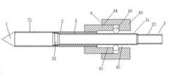
도 1과 도 2를 참고하면, 생검 회전 절제 장치는 동축으로 설치되는 내부 나이프 파이프(3)와 외부 나이프 파이프(2)를 포함하며, 상기 내부 나이프 파이프(3)는 상기 외부 나이프 파이프(2) 내측에 위치하고, 상기 외부 나이프 파이프(2)의 선단에는 천자용 헤드(1)가 설치되고, 상기 내부 나이프 파이프(3)의 상기 천자용 헤드(1)에서 먼 일단이 직접 또는 간접적으로 샘플 수집기에 연결되며, 이 직접 또는 간접적인 연결은 내부 나이프 파이프(3) 중의 조직을 샘플 수집기로 수송할 수 있는 것으로 이해할 수 있다.Referring to FIGS. 1 and 2 , the biopsy rotary ablation device includes an
외부 나이프 파이프(2)의 상기 천자용 헤드(1)에 가까운 관벽 부분에 칼날 홈(21)이 설치되며, 이에 대응하여 내부 나이프 파이프(3)의 천자용 헤드에서 가까운 일단에는 칼날 구조(33)가 구비되며, 칼날 홈(21)은 종양 조직을 외부 나이프 파이프(2)에 흡착하는데 사용되며, 나아가서, 칼날 홈(21)에 흡입된 조직은 칼날 구조(33)에 의해 잘리고, 잘린 후의 조직은 칼날 홈(21)의 내,외부 압력이 같으므로 쉽게 이동할 수 없으며, 상기 내부 나이프 파이프(3)의 상기 천자용 헤드(1)에서 먼 일단은 직접 또는 간접적으로 샘플 수집기에 연결된다. 이 샘플 수집기에는 외부와 접하는 음압 시스템을 배치할 수 있다. 일부 해결 수단 중에서, 음압 시스템의 음압 강도를 높여서 내외부의 압력 차를 변경할 수 있다.A
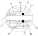
본 실시예에 있어서, 상기 장치는 상기 내부 나이프 파이프(3) 외측에 설치되는 동적 밀봉 구조(4)를 더 포함하며, 상기 동적 밀봉 구조(4)는 상기 내부 나이프 파이프(3) 밖에서 캐비티가 형성되고, 상기 내부 나이프 파이프(3)는 제1 파이프 구간(31)과 제2 파이프 구간(32)을 포함하며, 상기 제2 파이프 구간(32)의 상기 천자용 헤드(1)에서 가까운 일단은 상기 제1 파이프 구간(31)의 상기 천자용 헤드(1)에서 먼 일단에 설치되니, 즉, 상기 내부 나이프 파이프(3)는 상기 내부 나이프 파이프(3)의 축 방향을 따라 순서대로 설치되는 제1 파이프 구간(31)과 제2 파이프 구간(32)을 포함하고, 상기 제1 파이프 구간(31)의 일단은 상기 천자용 헤드(1)에 연결되며, 타단은 상기 제2 파이프 구간(32)에 연결되고, 상기 제2 파이프 구간(32)의 외경은 상기 제1 파이프 구간(31)의 외경보다 작고, 상기 동적 밀봉 구조(4) 내에는 밀봉링(43)이 설치되며, 상기 캐비티는 상기 밀봉링(43)의 상기 천자용 헤드(1)에서 가까운 일측에 위치하는 제1 캐비티(41)와, 상기 밀봉링(43)의 상기 천자용 헤드(1)에서 먼 일측에 위치하는 제2 캐비티(42)를 포함하며, 상기 제1 캐비티(41)는 상기 제1 파이프 구간(31) 외벽과 상기 외부 나이프 파이프(2) 내벽 사이의 파이프 사이 간극(5)과 연통하며, 상기 파이프 사이 간극(5)의 상기 천자용 헤드(1)에서 가까운 일단은 상기 내부 나이프 파이프(3)의 내측 공간과 연통한다.In this embodiment, the device further includes a dynamic sealing structure 4 installed outside the
그 중 파이프 사이 간극(5)의 천자용 헤드(1)에서 가까운 일단은 칼날 홈(21)에 가까운 일단으로 이해할 수도 있으며, 나아가서, 공기 유입 시에 생성되는 기류는 칼날 홈(21) 부근에 위치한 조직에 더욱 효과적으로 작용할 수 있다.Among them, the end close to the
상기 내부 나이프 파이프(3)가 축 방향을 따라 제1위치까지 이동할 때, 상기 밀봉링(43)은 상기 제2 파이프 구간(32)의 외측에 위치하면서, 상기 밀봉링(43)과 상기 제2 파이프 구간(32) 사이에 캐비티 사이 간극(46)을 가짐으로써 상기 제1 캐비티(41)와 상기 제2 캐비티(42)를 연통시킨다.When the
상기 내부 나이프 파이프(3)가 축 방향을 따라 제2위치까지 이동할 때, 상기 밀봉링(43)은 상기 제1 파이프 구간(31)의 외측에 위치하면서 상기 제1 파이프와(31) 밀봉 접촉함으로써, 상기 제1 캐비티(41)와 상기 제2 캐비티(42)를 차단한다.When the
제1 캐비티(41)와 제2 캐비티(42)는 내부 나이프 파이프(3) 외측에 둥글게 설치되는 환형의 캐비티로 이해할 수 있으며, 내부 나이프 파이프(3)의 축 방향을 따라 순서대로 분포되고, 제1 캐비티(41)는 파이프 사이 간극(5)과 연통하는 캐비티일 수 있고, 제2 캐비티(42)는 외부 공기와 간접 또는 직접적으로 연통하는 캐비티일 수 있으며, 예를 들어 후단 공간(6)을 통해 외부 공기와 연통하며, 나아가서, 제1 캐비티(41)와 제2 캐비티(42)가 연통할 때, 외부 공기를 유입할 수 있다.The
제1 위치는 캐비티 사이 간극(46)이 제1 캐비티(41)와 제2 캐비티(42)를 연통시킬 수 있는 임의의 위치로 이해할 수 있으며, 구체적으로는 칼날 구조(33)가 외부 나이프 파이프(2)의 칼날 홈(21) 내에 위치하는 위치일 수 있는바, 즉 상기 내부 나이프 파이프(3)가 축 방향을 따라 상기 제1 위치까지 이동할 때, 상기 칼날 구조(33)는 상기 칼날 홈(21) 내에 위치하게 된다.The first position can be understood as an arbitrary position where the
제2 위치는 캐비티 사이 간극(46)이 제1 캐비티(41)와 제2 캐비티(42)를 차단할 수 있는 임의의 위치로 이해할 수 있으며, 구체적으로는 칼날 구조(33)가 외부 나이프 파이프(2)의 칼날 홈(21) 내에 위치하지 않는 위치일 수 있는바, 즉 상기 내부 나이프 파이프(3)가 축 방향을 따라 상기 제2위치까지 이동할 때, 상기 칼날 구조(33)는 상기 칼날 홈(21) 내측에 위치하지 않게 된다. 이때, 시스템이 제공하는 음압은 조직이 칼날 홈(21)으로 유입되도록 하기에 충분하다.The second position can be understood as an arbitrary position where the
칼날 구조(33)는 상기 제1 파이프 구간(31)의 상기 천자용 헤드(1)에서 가까운 일단에 설치할 수 있다.The
본 실시예가 제공하는 생검 회전 절제 장치는 샘플링 효과가 좋지 않다는 점을 고려하여, 공기를 외부에서 유입하여 등압 상태를 타파함으로써, 조직이 고효율적으로 흡입 인출될 수 있도록 하는데, 그중에서, 본 발명은 동적 밀봉 구조와 그 중의 밀봉링을 통해, 내,외부 파이프 사이의 파이프 사이 간극과 연통할 수 있는 제1 캐비티 및 외부 공기와 연통할 수 있는 제2 캐비티를 제공하며, 회전 절제 시 내부 나이프 파이프가 제2위치까지 이동할 때, 제1 캐비티와 제2 캐비티는 밀봉링으로 밀폐되며, 밀폐된 상태에서 조직을 칼날 홈으로 흡입할 수 있고, 회전 절제 이후에 칼날 홈 주위와 내부 나이프 파이프 내에서 발생하는 압력의 강도는 동일하며, 내부 나이프 파이프가 제1 위치로 이동할 때, 제1 캐비티와 제2 캐비티는 제2 파이프 구간 밖의 캐비티 사이 간극을 통해 연통하며, 공기를 유입하여 흡입 인출 강도가 더욱 우수한 순환 기류를 형성할 수 있으며, 이 순환 기류는 순서대로 제2 캐비티, 캐비티 사이 간극, 제1 캐비티, 파이프 사이 간극을 거치며, 파이프 사이 간극의 천자용 헤드에서 가까운 일단을 거쳐서 내부 나이프 파이프 내로 들어오고, 이 순환 기류는 회전하여 잘린 조직을 더욱 고효율적으로 후단의 샘플 수집기로 이송할 수 있으며 샘플링 비율을 효과적으로 높일 수 있다.Considering the fact that the sampling effect is not good, the rotational biopsy apparatus provided by the present embodiment breaks the isobaric state by introducing air from the outside, so that tissue can be suctioned and drawn out with high efficiency. Among them, the present invention provides Through the dynamic sealing structure and the sealing ring therein, a first cavity that can communicate with the gap between the inner and outer pipes and the second cavity that can communicate with the outside air is provided, and the inner knife pipe during rotational cutting When moving to the second position, the first cavity and the second cavity are sealed with a sealing ring, and in the closed state, tissue can be sucked into the blade groove, and after rotational ablation, the occurrence around the blade groove and in the inner knife pipe The strength of the pressure is the same, and when the inner knife pipe moves to the first position, the first cavity and the second cavity communicate through the gap between the cavities outside the second pipe section, and the air is introduced into the circulation with better suction and withdrawal strength. An airflow may be formed, and this circulating airflow passes through the second cavity, the gap between the cavities, the first cavity, and the gap between the pipes in order, and enters the inner knife pipe through one end close to the puncture head of the gap between the pipes, This circulating airflow can rotate and transfer the cut tissue to the sample collector at the rear stage more efficiently and effectively increase the sampling rate.
동시에, 본 실시예의 제1 캐비티와 제2 캐비티는 내부 나이프 파이프의 축 방향을 따라 분포되는 것으로서, 캐비티 사이 간극도 내부 나이프 파이프의 축 방향을 따라 제1 캐비티와 제2 캐비티 사이에 설치되므로, 생성되는 기류의 전체적인 흐름의 방향도 축 방향을 따르며, 비교적 큰 굴곡 등의 상황이 발생하지 않고, 흐름의 방향에 있어서 비교적 우수한 일치성을 유지할 뿐만 아니라, 기류 이동 과정이 늘어나지 않게 되어, 조직 수송의 효율을 한층 높이고 샘플링 비율을 확실하게 높일 수 있다.At the same time, the first cavity and the second cavity in this embodiment are distributed along the axial direction of the inner knife pipe, and the gap between the cavities is also installed between the first cavity and the second cavity along the axial direction of the inner knife pipe, thus creating The direction of the overall flow of the airflow is also along the axial direction, and there is no situation such as a relatively large bend, and not only maintains a relatively good consistency in the direction of the flow, but also the airflow movement process does not increase, resulting in the efficiency of tissue transport. can be further increased and the sampling rate can be significantly increased.
본 실시예에서, 제1 캐비티와 제2 캐비티의 연통 및 차단은 내부 나이프 파이프의 이동 자체를 통해 가져오는 것이며, 그 사이에는 인위적이거나 기계적인 조작 제어가 별도로 필요하지 않고, 한편으로 연통과 차단의 적시성을 보장할 뿐만아니라 또 한편으로는 연통과 차단이 내부 나이프 파이프의 이동 자체에 대한 불리한 영향, 예를 들면 저항력 등을 줄일 수도 있다.In this embodiment, the communication and blocking of the first cavity and the second cavity are brought about through the movement of the inner knife pipe itself, and no artificial or mechanical operation control is required between them. Not only does it ensure timeliness, but on the other hand, communication and blocking can also reduce adverse effects on the movement itself of the inner knife pipe, such as resistance.
이 외에, 본 실시예는 다른 인위적이거나 기계적인 조작 제어가 필요하지 않으므로, 본 실시예는 다른 조작 제어로 인해 늘어나는 구조적인 마모를 피할 수 있어서, 마모를 줄이고 노화 속도를 늦추며 사용 수명을 높이므로, 유지보수 원가를 낮추는 것에도 유리하다. 동시에, 본 실시예는 예를 들면 복원 부품, 구동 부품 등과 같은 조작 제어에 사용되는 다른 기계 구조가 필요하지 않으므로, 동적 밀봉 구조, 나이프 파이프 등 사이의 기밀도를 효과적으로 보장할 수 있어서, 회전 절제 과정 중 고속 운동의 수요(회전 절제 칼의 회전 속도는 매우 빠르므로, 초당 예를 들어 r=300rpm에 달하기도 함)를 충족시킬 수 있다. 도 3은 본 발명 다른 일 실시예에 따른 생검 회전 절제 장치의 상태를 도시한 첫 번째 개략도이며, 도 4는 도 3중 A구역을 부분적으로 확대한 개략도이고, 도 5는 도 4중 C구역을 부분적으로 확대한 개략도이며, 도 6은 도 3중 B구역을 부분적으로 확대한 개략도이며, 도 7은 본 발명 다른 일 실시예에 따른 생검 회전 절제 장치의 상태를 도시한 두 번째 개략도이고, 도 8은 도 7중 D구역을 부분적으로 확대한 개략도이다.In addition, since this embodiment does not require any other artificial or mechanical operation control, this embodiment can avoid the structural wear caused by other operation control, thereby reducing wear and tear, slowing down the aging rate, and increasing the service life. , it is also advantageous to lower maintenance costs. At the same time, this embodiment does not require other mechanical structures used for operation control, such as restoring parts, driving parts, etc., so that the dynamic sealing structure, the airtightness between the knife pipe and the like can be effectively ensured, so that the rotary ablation process It can meet the demand of medium-high-speed motion (the rotational speed of the rotary cutting knife is very fast, reaching, for example, r=300 rpm per second). 3 is a first schematic diagram showing a state of a rotary biopsy resection device according to another embodiment of the present invention, FIG. 4 is a partially enlarged schematic view of area A in FIG. 3, and FIG. 5 shows area C in FIG. FIG. 6 is a partially enlarged schematic view of area B in FIG. 3, FIG. 7 is a second schematic view showing a state of a biopsy rotational ablation device according to another embodiment of the present invention, and FIG. 8 is a partially enlarged schematic view. is a schematic diagram in which area D in FIG. 7 is partially enlarged.
본 실시예에서, 도 1, 도 2, 도 3, 도 6, 도 7과 도 8을 참고하면, 내부 나이프 파이프(3)는 회전하여 가장 먼 위치, 즉 도 1, 도 2, 도 3과 도 7에서 표시된 가장 좌측으로 전진하며, 이때 외부 나이프 파이프(2)의 칼날 홈(21)은 내부 나이프 파이프(3)의 헤드부, 예를 들어 칼날 구조(33)을 포함하는 일부분이 차지하게 되는데, 이 상황은 천자 단계로 이해할 수 있으며, 구체적으로는 도 2와 도 3에 표시된 위치를 참고하여 이해할 수 있으며, 상기 제1위치로 이해할 수도 있다.In this embodiment, referring to Figs. 1, 2, 3, 6, 7 and 8, the
천자가 완료된 후, 내부 나이프 파이프(3)가 도 1, 도 7과 도 8에 표시된 위치까지 후진하는데, 이것은 제2 위치까지 후진하는 것으로도 이해할 수 있으며, 이때 예를 들어 칼날 구조(33)의 헤드부는 마침 칼날 홈(21)을 막지 않으며, 이 상황은 천자 완료 후 조직을 흡착하는 단계이고, 이때, 제1 캐비티(41)와 제2 캐비티(42)가 분리되며, 제1 캐비티(41), 파이프 사이 간극(5), 칼날 구조(33)의 내측 공간 및 제1 파이프 구간(31)의 내측 공간은 순서대로 연통하면서 제2 캐비티(42)와 밀봉 차단되고, 음압 시스템을 이용하여 조직을 칼날 홈(21)으로 흡입할 수 있으며, 조직이 칼날 홈(21)으로 흡입된 후, 내부 나이프 파이프(3)는 회전 전진 동작을 중복하여 도 2와 도 3에 표시된 위치에 도달한다, 즉 다시 제1 위치로 돌아들어오게 되는데, 이 과정 중에서 흡입된 조직이 칼날 구조(33)에 의해 절제된다.After the puncture is completed, the
내부 나이프 파이프(3)의 전진에 따라, 밀봉링(43)이 다시 제2 파이프 구간(32)의 외측에 도달하여 캐비티 사이 간극(46)을 형성하며, 이때 공기는 순서대로 제2 캐비티(42), 캐비티 사이 간극(46), 제1 캐비티(41), 파이프 사이 간극(5), 칼날 구조(33)의 내측 공간 및 제1 파이프 구간(31)의 내측 공간을 거쳐 흡출 강도가 더욱 좋은 순환 기류를 형성하고, 나아가서, 조직은 지속적인 음압과 유입되는 공기에 의해 샘플 수집기로 수송되면서 한 차례의 조직 수집을 완료한다.As the
그중에서 한 차례 흡착과 회전 절제가 완료된 후, 칼날 홈(21) 주위의 압력 강도는 내부 나이프 파이프(3) 내의 압력과 같으며, 시스템의 음압과도 같고, 별도의 공기가 외부로부터 칼날 홈(21)에 유입되지 않을 경우, 전체 칼 세트는 등압 상태에 놓이고, 흡착 절제된 조직은 칼날 홈(21)에서 샘플 수집기로 유출될 수 없거나 유출되기 힘들다. 그러므로 본 실시 형태는 공기의 유입을 통해 조직의 유출을 효과적으로 실현하였다.Among them, after the adsorption and rotational ablation are completed once, the pressure around the
이상의 과정은 한 차례 천자, 흡착, 회전 절제, 수집의 주기를 완성한 것임을 알 수 있으며, 이후 내부 나이프 파이프(3)는 절제가 필요한 조직을 깨끗하게 잘라낼때까지 이전 주기의 일부 또는 모든 운동을 여러 차례 중복할 수 있다.It can be seen that the above process completes the cycle of puncture, adsorption, rotational ablation, and collection once, and then the inner knife pipe (3) repeats all or part of the previous cycle several times until the tissue that needs to be resected is cut cleanly. can do.
그 중, 칼날 구조(33)의 내측 공간과 파이프 사이 간극(5)의 연통을 실현하기 위하여, 본 실시예의 바람직한 해결 수단 중에서, 제1 파이프 구간(31)의 일단 칼날 구조(33)의 구조 차이에 따라, 파이프 사이 간극(5)과 내부 나이프 파이프(3) 내측 공간을 연통하는 서로 다른 형태를 실현할 수 있다.Among them, in order to realize the communication between the inner space of the
그 중 한 가지 실시 형태에서, 칼날 구조(33)의 둘레와 외부 나이프 파이프(2) 내벽 사이에 간격이 있을 수 있고, 나아가서, 파이프 사이 간극(5)은 이 간격을 통해 칼날 구조(33)의 천자용 헤드(1)에 가까운 일측의 공간, 즉 칼날 구조(33)와 천자용 헤드(1) 사이의 외부 나이프 파이프(2) 내의 공간에 연통되며, 나아가서, 칼날 구조(33)의 내측 공간에 연통될 수 있다. 다른 바람직한 실시 형태에서, 칼날 구조(33)의 둘레는 간격이 없거나 비교적 작은 간격일 수도 있으며, 나아가서, 간격이 없어도 내부 나이프 파이프(3)가 외부 나이프 파이프(2) 내에서 운동을 방해하지 않는 구조 형식일 수 있다.In one embodiment of them, there may be a gap between the circumference of the
도 4를 참고하고, 또 다른 첨부 도면을 결합하면, 파이프 사이 간극(5)은 칼날 구조(33) 통기 틈새(34)에 설치됨으로써 칼날 구조(33) 내측과 연통될 수 있다. 이는 상기 장치는 상기 내부 나이프 파이프(3)의 축 방향을 따라 설치되는 통기 틈새(34)를 더 포함할 수도 있으며, 상기 통기 틈새(34)는 상기 칼날 구조(33)에 설치되거나 상기 칼날 구조(33)와 상기 제1 파이프 구간(31)에 설치될 수 있으며, 상기 통기 틈새(34)는 상기 칼날 구조(33)의 내측 공간과 상기 파이프 사이 간극(5)을 연통시키며, 상기 칼날 구조(33)의 내측 공간은 상기 제1 파이프 구간(31)의 내측 공간과 연통하는 것으로 이해할 수 있다.Referring to FIG. 4 and combining other accompanying drawings, the
통기 틈새(34)의 설치는 파이프 사이 간극(5)이 칼날 구조(33) 외측의 간격을 통해 칼날 구조(33)의 천자용 헤드(1)에서 가까운 일측의 공간에 연결될 수 있는지 여부를 막론하고, 본 실시 형태 모두 파이프 사이 간극(5)의 천자용 헤드(1)에서 가까운 일단이 내부 나이프 파이프(3)의 내측 공간에 연결될 수 있으며, 나아가서, 순환 기류를 통해 조직의 흡입 및 조직의 수집 수요를 충족시키는 것을 보장할 수 있다.The installation of the
그 중 한 가지 실시 형태에서, 도 4와 도 5를 참고하면, 상기 칼날 구조(33)는 환형의 칼날 연결부(331)와 칼끝부(332)를 포함하며, 상기 칼끝부(332)는 상기 칼날 연결부(331)의 상기 천자용 헤드(1)에서 가까운 일단에 설치되며, 상기 칼날 연결부(331)의 상기 천자용 헤드(1)에서 먼 일단은 상기 제1 파이프 구간(31)의 상기 천자용 헤드(1)에 가까운 일단과 연결된다. 나아가서, 칼끝부(332)는 외부 빗면(334), 내부 빗면(335)을 가질 수 있으며, 외부 빗면(334)과 내부 빗면(335)은 연결되어 칼끝부(332)의 말단(333)을 형성할 수 있다.In one embodiment, referring to FIGS. 4 and 5 , the
그 중, 상기 칼날 연결부(331)의 외경은 상기 제1 파이프 구간(31)의 외경보다 크고, 상기 외부 나이프 파이프(2)의 내경보다 작을 수 있으며, 상기 칼끝부(332)의 상기 천자용 헤드(1)의 말단(333)에서 가까운 직경은 상기 외부 나이프 파이프(2)의 내경보다 클 수 있다. 구체적인 실시 과정에서, 칼날 연결부(331)의 내경은 제1 파이프 구간(31)의 내경보다 클 수도 있다.Among them, the outer diameter of the
그 중 한 가지 실시 형태에서, 도 4를 참고하면, 상기 통기 틈새(34)는 상기 내부 나이프 파이프(3)의 축 방향을 따라 설치되는 주요 틈새부(341) 및 상기 주요 틈새부(341) 양단에 각각 설치되는 원형 단부(342)를 포함하며, 나아가서, 하나의 원형 단부(342)는 칼날 연결부(331)에 설치하고, 다른 한 원형 단부(342)는 제1 파이프 구간(31)에 설치할 수 있다. 내부 나이프가 어떤 각도로 회전하든 공기가 원형 단부(342)에서 칼날 구조(33)의 내측 공간으로 유입되는 것을 보장할 수 있다.In one embodiment, referring to FIG. 4 , the
그 중, 원형 단부(342)의 직경은 주요 틈새부(341)의 폭보다 크다.Among them, the diameter of the
도 9는 본 발명 일 실시예에 따른 통기 틈새의 분포 개략도이다.9 is a schematic diagram of the distribution of ventilation gaps according to an embodiment of the present invention.
그 중 한 가지 실시 형태에서, 도 9를 참고하면, 상기 통기 틈새(34)의 수량은 복수 개이며, 복수의 통기 틈새(34)는 상기 내부 나이프 파이프(3)의 축을 둘러싼 방향에서 고르게 분포한다. 나아가서, 서로 인접하는 두 통기 틈새(34)는 원주방향에서의 간격이 칼날 홈(21)이 원주 방향에서의 크기보다 작다. 도 9에 나타난 바와 같이, 예를 들어 6개의 통기 틈새(34)는 원주방향을 따라 고르게 분포되도록 설치하여, 내부 나이프 파이프가 어느 각도로 회전하든, 항상 통기 틈새(34)가 외부 나이프 파이프(2)의 칼날 홈(21) 안에 있게 되며, 나아가서, 생성되는 기류는 칼날 홈(21) 부근을 지날 수 있게 보장될 수 있다.In one embodiment, referring to FIG. 9 , the number of
그 중 한 가지 실시 형태에서, 상기 동적 밀봉 구조(4)는 밀봉 받침판(44)과 밀봉 슬리브(45)를 포함하며, 상기 밀봉 받침판(44)은 상기 외부 나이프 파이프(2) 밖에 고정 연결되며, 직접 연결할 수도 있고 간접적으로 연결할 수도 있으며, 상기 밀봉 슬리브(45)는 상기 밀봉 받침판(44)과 고정 연결되고, 상기 밀봉 슬리브(45)와 상기 밀봉 받침판(44)은 상기 내부 나이프 파이프(3)의 축 방향을 따라 설치 간극을 가지며, 상기 밀봉링(43)은 상기 설치 간극에 설치되고, 상기 밀봉 슬리브(45)는 상기 내부 나이프 파이프(3) 외측에 위치하며, 상기 제1 캐비티(41)는 상기 밀봉 받침판(44) 내에 위치하고, 상기 제2 캐비티(42)는 상기 밀봉 슬리브(45) 내에 위치한다.In one embodiment, the dynamic sealing structure 4 includes a sealing
그 중에서, 밀봉 받침판(44)은 구동판 구조(7)와 고정 연결될 수 있다, 예를 들어 밀봉 받침판(44)의 헤드부 단면은 구동판 구조(7) 중 구동판 받침판(72)의 안쪽 단면 사이와 연결되고 완전하게 밀봉될 수 있으며, 연결 방식은 접착제 접합, 레이저 용접 등의 방식으로 제한을 두지 않는다. 밀봉 받침판(44) 헤드부 단면과 구동판 구조(7)의 구동판 본체(71) 안쪽 단면 사이에는 일정한 간극이 있고, 구동판 본체(71)가 외부 나이프 파이프(2)의 축선을 둘러싸고 회전하도록 보장한다.Among them, the sealing
더 바람직한 실시 형태, 또는 다른 바람직한 실시 형태 중에서, 외부 나이프 파이프(2)의 외부 표면 역시 밀봉 받침판(44) 내부 표면과 고정 연결될 수 있으며, 고정 방식은 접착제 접합, 레이저 용접 등의 방식으로 제한을 두지 않는다.In a more preferred embodiment or other preferred embodiments, the outer surface of the
구체적인 실시 과정 중에서, 도 6과 도 8을 참고하면, 상기 밀봉 슬리브(45)는 슬리브 본체(452)와 슬리브 연결부(451)를 포함하며, 상기 슬리브 연결부(451)는 상기 슬리브 본체(452)의 상기 천자용 헤드(1)에서 가까운 일측에 설치되고, 상기 슬리브 연결부(451)의 내측은 상기 밀봉 받침판(44)의 외측에 고정 연결되며, 상기 슬리브 본체(452)와 상기 밀봉 받침판(44)은 상기 내부 나이프 파이프(3)의 축 방향을 따라 간격을 두고 설치됨으로써 상기 설치 간극을 형성한다. 이 설치 간극의 크기는 밀봉링(43)의 크기와 매칭되고, 나아가서, 밀봉링(43)의 설치를 구현하는 데에 적합할 수 있다.Among the specific implementation processes, referring to FIGS. 6 and 8 , the sealing
밀봉 받침판(44) 외부 표면과 밀봉 슬리브(45) 내부 표면 사이의 연결 고정 방식은 다양하며, 접착제 접합, 나사 체결 등의 방식으로 제한을 두지 않는다.There are various ways of fixing the connection between the outer surface of the sealing
기타 바람직한 형태 중에서, 밀봉 슬리브(45)와 밀봉 받침판(44)은 일체형일 수 있으며, 나아가서, 임의로 설치 간극을 형성할 수도 있고, 또한 외부 나이프 파이프(2)와 직접 또는 간접적으로 연결할 수 있는 일체식 또는 조립식의 동적 밀봉 구조(4) 모두 본 실시예의 설명 범위를 벗어나지 않는다.Among other preferred forms, the sealing
이 외에, 구동판 구조(7)의 천자용 헤드(1)에서 먼 일측에 후면 슬리브(8)가 연결되고, 후단 공간(6)은 후면 슬리브(8) 내에 위치할 수 있으며, 밀봉 슬리브(45)도 후면 슬리브(8) 내측에 위치할 수 있고, 밀봉 받침판(44)은 구동판 구조(7)의 구동판 받침판(72)의 내측에 위치할 수 있다.In addition, the
상술한 바와 같이, 본 실시예가 제공하는 생검 회전 절제 장치는 샘플링 효과가 좋지 않다는 점을 고려하여, 공기를 외부에서 유입하는 것으로 등압 상태를 타파함으로써, 조직이 고효율적으로 흡입 인출될 수 있도록 하는데, 그중에서, 본 발명은 동적 밀봉 구조와 그 중의 밀봉링을 통해, 내,외부 파이프 사이의 파이프 사이 간극과 연통할 수 있는 제1 캐비티 및 외부 공기와 연통할 수 있는 제2 캐비티를 제공하며, 회전 절제 시, 내부 나이프 파이프가 제2 위치까지 이동할 때, 제1 캐비티와 제2 캐비티는 밀봉링으로 밀폐되며, 밀폐된 상태에서 조직을 칼날 홈으로 흡입할 수 있고, 회전 절제 이후에 칼날 홈 주위와 내부 나이프 파이프 내에서 발생하는 압력의 강도는 동일하며, 내부 나이프 파이프가 제1 위치로 이동할 때, 제1 캐비티와 제2 캐비티는 제2 파이프 구간 밖의 캐비티 사이 간극을 통해 연통하며, 공기를 유입하여 흡입 인출 강도가 더욱 우수한 순환 기류를 형성할 수 있으며, 이 순환 기류는 순서대로 제2 캐비티, 캐비티 사이 간극, 제1 캐비티, 파이프 사이 간극을 거치며, 파이프 사이 간극의 천자용 헤드에서 가까운 일단을 거쳐서 내부 나이프 파이프 내로 들어오고, 이 순환 기류는 회전하여 잘린 조직을 더욱 고효율적으로 후단의 샘플 수집기로 이송할 수 있으며, 샘플링 비율을 효과적으로 높일 수 있다.As described above, in consideration of the fact that the sampling effect is not good, the rotational biopsy apparatus provided by the present embodiment breaks the isobaric state by introducing air from the outside, so that the tissue can be suctioned out with high efficiency. Among them, the present invention provides a first cavity that can communicate with the inter-pipe gap between the inner and outer pipes and a second cavity that can communicate with the outside air through a dynamic sealing structure and a sealing ring therein, and rotates During resection, when the inner knife pipe moves to the second position, the first cavity and the second cavity are sealed with a sealing ring, and tissue can be sucked into the blade groove in the closed state, and after rotational resection, around the blade groove and The intensity of the pressure generated in the inner knife pipe is the same, and when the inner knife pipe moves to the first position, the first cavity and the second cavity communicate through the gap between the cavities outside the second pipe section, and the air is introduced to It is possible to form a circulating airflow with better suction and drawing strength, which sequentially passes through the second cavity, the gap between the cavities, the first cavity, and the gap between the pipes, and passes through one end of the gap between the pipes close to the puncture head. Entered into the inner knife pipe, this circulating airflow can rotate and transfer the cut tissue to the sample collector at the rear stage more efficiently, effectively increasing the sampling rate.
동시에, 본 실시예의 제1 캐비티와 제2 캐비티는 내부 나이프 파이프의 축 방향을 따라 분포되는 것으로서, 캐비티 사이 간극도 내부 나이프 파이프의 축 방향을 따라 제1 캐비티와 제2 캐비티 사이에 설치되므로, 생성되는 기류의 전체적인 흐름의 방향도 축 방향을 따르며, 비교적 큰 굴곡 등의 상황이 발생하지 않고, 흐름의 방향에 있어서 비교적 높은 일치성을 유지할 뿐만 아니라, 기류 이동 과정이 늘어나지 않게 되어, 조직 수송의 효율을 한층 높이고 샘플링 비율을 확실하게 높일 수 있다.At the same time, the first cavity and the second cavity in this embodiment are distributed along the axial direction of the inner knife pipe, and the gap between the cavities is also installed between the first cavity and the second cavity along the axial direction of the inner knife pipe, thus creating The direction of the overall flow of the airflow is also along the axial direction, and there is no situation such as a relatively large bend, and not only maintains a relatively high consistency in the direction of the flow, but also the airflow movement process does not increase, and the efficiency of tissue transport can be further increased and the sampling rate can be significantly increased.
본 실시예 중, 제1 캐비티와 제2 캐비티의 연통 및 차단은 내부 나이프 파이프의 이동 자체를 통해 가져오는 것이며, 그 사이에는 인위적이거나 기계적인 조작 제어가 별도로 필요하지 않고, 한편으로 연통과 차단의 적시성을 보장할 뿐만아니라, 또 한편으로는 연통과 차단이 내부 나이프 파이프의 이동 자체에 대한 불리한 영향, 예를 들면 저항력 등을 줄일 수도 있다.In this embodiment, the communication and blocking of the first cavity and the second cavity are brought about through the movement of the inner knife pipe itself, and no artificial or mechanical operation control is required between them. In addition to ensuring timeliness, on the other hand, communication and blocking can also reduce adverse effects on the movement itself of the inner knife pipe, such as resistance.
이 외에, 본 실시예는 다른 인위적이거나 기계적인 조작 제어가 필요하지 않으므로, 본 실시예는 다른 조작 제어로 인해 늘어나는 구조적인 마모를 피할 수 있어서, 마모를 줄이고 노화 속도를 늦추며 사용 수명을 높이므로, 유지보수 원가를 낮추는 것에도 유리하다. 동시에, 본 발명은 예를 들면 복원 부품, 구동 부품 등과 같은 조작 제어에 사용되는 다른 기계 구조가 필요하지 않으므로, 동적 밀봉 구조, 나이프 파이프 등 사이의 기밀도를 효과적으로 보장할 수 있어서, 회전 절제 과정 중 고속 운동의 수요(회전 절제 칼의 회전 속도는 매우 빠르므로, 초당 예를 들어 r=300rpm에 달하기도 함)를 충족시킬 수 있다In addition, since this embodiment does not require any other artificial or mechanical operation control, this embodiment can avoid the structural wear caused by other operation control, thereby reducing wear and tear, slowing down the aging rate, and increasing the service life. , it is also advantageous to lower maintenance costs. At the same time, the present invention does not require other mechanical structures used for operation control, such as restoring parts, driving parts, etc., and can effectively ensure the tightness between the dynamic sealing structure, the knife pipe, etc., during the rotational ablation process. Can meet the demand of high-speed movement (rotational speed of rotary cutting knife is very fast, reaching r=300rpm per second, for example)
마지막으로 설명해야 할 것은, 이상의 각 실시예는 단지 본 발명의 과제 해결 수단을 설명하는 데 사용될 뿐, 이를 제한하는 것은 아니라는 점이며, 설령 전술한 각 실시예를 참고하여 본 발명에 대해 상세하게 설명하였더라도, 본 발명이 속하는 기술 분야에서 통상의 지식을 가진 자는 여전히 전술한 각 실시예에 기재된 과제 해결 수단에 대해 수정을 하거나 그중의 일부 또는 전체 기술 특징에 대해 동등한 대체를 할 수 있고, 이처럼 수정이나 대체를 하였더라도, 해당 과제 해결 수단의 본질은 본 발명 각 실시예의 과제 해결 수단의 범위에서 벗어나지 않는다고 이해하여야 한다.Finally, it should be noted that each of the above embodiments is only used to explain the means for solving the problems of the present invention, but does not limit them, even if the present invention is described in detail with reference to each of the above-described embodiments. Even if this is the case, a person skilled in the art to which the present invention belongs may still make modifications to the problem-solving means described in each of the foregoing embodiments or make equivalent substitutions for some or all of the technical features, and thus modifications or Even if it is replaced, it should be understood that the nature of the problem solving means does not deviate from the scope of the problem solving means of each embodiment of the present invention.
1: 천자용 헤드;
2: 외부 나이프 파이프;
21: 칼날 홈;
3: 내부 나이프 파이프;
31: 제1 파이프 구간;
32: 제2 파이프 구간 ;
33: 칼날 구조;
331: 칼날 연결부;
332: 칼끝부
333: 말단;
334: 외부 빗면;
335: 내부 빗면;
34: 통기 틈새;
341: 주요 틈새부;
342: 원형 단부;
4: 동적 밀봉 구조;
41: 제1 캐비티;
42: 제2 캐비티;
43: 밀봉링;
44: 밀봉 받침판;
45: 밀봉 슬리브;
451: 슬리브 연결부;
452: 슬리브 본체;
46: 캐비티 사이 간극;
5: 파이프 사이 간극;
6: 후단 공간;
7: 구동판 구조;
71: 구동판 본체;
72: 구동판 받침판;
8: 후면 슬리브1: puncture head;
2: external knife pipe;
21: blade groove;
3: inner knife pipe;
31: first pipe section;
32: 2nd pipe section;
33: blade structure;
331: blade connection portion;
332: knife tip
333 terminal;
334: external bevel;
335: inner bevel;
34: ventilation gap;
341 main gap;
342 circular end;
4: dynamic sealing structure;
41: first cavity;
42: second cavity;
43: sealing ring;
44: sealing support plate;
45: sealing sleeve;
451: sleeve connection;
452: sleeve body;
46: gap between cavities;
5: Gap between pipes;
6: trailing edge space;
7: driving plate structure;
71: driving plate body;
72: drive plate support plate;
8: rear sleeve
Claims (10)
Translated fromKorean상기 내부 나이프 파이프 외측에 설치되는 동적 밀봉 구조를 더 포함하며,
상기 동적 밀봉 구조는 상기 내부 나이프 파이프 밖에서 캐비티가 형성되고, 상기 내부 나이프 파이프는 상기 내부 나이프 파이프의 축 방향을 따라 순서대로 설치되는 제1 파이프 구간과 제2 파이프 구간을 포함하며, 상기 제1 파이프 구간의 일단은 상기 천자용 헤드와 연결되며, 타단은 상기 제2 파이프 구간과 연결되고, 상기 제2 파이프 구간의 외경은 제1 파이프 구간의 외경보다 작고, 상기 동적 밀봉 구조 내에 밀봉링이 설치되며, 상기 캐비티는 상기 밀봉링의 상기 천자용 헤드에서 가까운 일측에 위치하는 제1 캐비티와 상기 밀봉링의 상기 천자용 헤드에서 먼 일측에 위치하는 제2 캐비티를 포함하며, 상기 제1 캐비티는 상기 제1 파이프 구간 외벽과 상기 외부 나이프 파이프 내벽 사이의 파이프 사이 간극을 연통하며, 상기 파이프 사이 간극의 상기 천자용 헤드에서 가까운 일단은 상기 내부 나이프 파이프의 내측 공간과 연통하고,
상기 내부 나이프 파이프가 축 방향을 따라 제1위치까지 이동할 때, 상기 밀봉링은 상기 제2 파이프 구간의 외측에 위치하면서, 상기 밀봉링과 상기 제2 파이프 구간 사이에 캐비티 사이 간극을 가짐으로써 상기 제1 캐비티 및 상기 제2 캐비티를 연통시키고;,
상기 내부 나이프 파이프가 축 방향을 따라 제2위치까지 이동할 때, 상기 밀봉링은, 상기 제1 파이프 구간의 외측에 위치하고, 상기 제1 파이프와 밀봉 접촉함으로써, 상기 제1 캐비티와 상기 제2 캐비티를 차단하는,
생검 회전 절제 장치.It includes an inner knife pipe and an outer knife pipe installed coaxially, wherein the inner knife pipe is located inside the outer knife pipe, a puncture head is installed at the front end of the outer knife pipe, and the puncture head of the inner knife pipe is installed. A biopsy rotary ablation device having one end remote from the head directly or indirectly connected to a sample collector, comprising:
Further comprising a dynamic sealing structure installed outside the inner knife pipe,
In the dynamic sealing structure, a cavity is formed outside the inner knife pipe, the inner knife pipe includes a first pipe section and a second pipe section installed in sequence along an axial direction of the inner knife pipe, One end of the section is connected to the puncture head, the other end is connected to the second pipe section, the outer diameter of the second pipe section is smaller than the outer diameter of the first pipe section, and a sealing ring is installed in the dynamic sealing structure; , The cavity includes a first cavity located on one side of the sealing ring close to the puncture head and a second cavity located on one side of the sealing ring far from the puncture head, wherein the first cavity is the first cavity. 1 communicates with the pipe gap between the outer wall of the pipe section and the inner wall of the outer knife pipe, and the end of the pipe gap close to the puncture head communicates with the inner space of the inner knife pipe;
When the inner knife pipe moves to the first position along the axial direction, the sealing ring is located outside the second pipe section and has a cavity gap between the sealing ring and the second pipe section, thereby providing the first communicating the first cavity and the second cavity;
When the inner knife pipe moves to the second position along the axial direction, the sealing ring is located outside the first pipe section and makes sealing contact with the first pipe, thereby sealing the first cavity and the second cavity. blocking,
Biopsy rotary resection device.
상기 제1 파이프 구간의 상기 천자용 헤드에서 가까운 일단에 칼날 구조가 설치되고, 상기 외부 나이프 파이프의 상기 천자용 헤드에서 가까운 관벽 부분에 칼날 홈이 설치되며, 상기 내부 나이프 파이프의 상기 천자용 헤드에서 먼 일단은 직접 또는 간접적으로 샘플 수집기에 연결되며,
상기 내부 나이프 파이프가 축 방향을 따라 상기 제1위치까지 이동할 때, 상기 칼날 구조가 상기 칼날 홈 내에 위치하고, 상기 내부 나이프 파이프가 축 방향을 따라 상기 제2위치까지 이동할 때, 상기 칼날 구조가 상기 칼날 홈 내측에 위치하지 않는,
생검 회전 절제 장치.According to claim 1,
A blade structure is installed at one end of the first pipe section close to the puncture head, a blade groove is installed on the pipe wall portion of the outer knife pipe close to the puncture head, and at the puncture head of the inner knife pipe The far end is connected directly or indirectly to the sample collector;
When the inner knife pipe moves along the axial direction to the first position, the blade structure is located in the blade groove, and when the inner knife pipe moves along the axial direction to the second position, the blade structure is positioned in the blade groove. not located inside the groove,
Biopsy rotary resection device.
상기 내부 나이프 파이프의 축 방향을 따라 설치되는 통기 틈새를 더 포함하며, 상기 통기 틈새는 상기 칼날 구조에 설치되거나, 상기 칼날 구조와 상기 제1 파이프 구간에 설치되고, 상기 통기 틈새는 상기 칼날 구조의 내측 공간과 상기 파이프 사이 간극을 연통시키며, 상기 칼날 구조의 내측 공간은 상기 제1 파이프 구간의 내측 공간과 연통하는,
생검 회전 절제 장치.According to claim 2,
Further comprising a ventilation gap installed along the axial direction of the inner knife pipe, the ventilation gap is installed in the blade structure or between the blade structure and the first pipe section, the ventilation gap is provided in the blade structure The gap between the inner space and the pipe communicates, and the inner space of the blade structure communicates with the inner space of the first pipe section.
Biopsy rotary resection device.
상기 통기 틈새의 수량은 복수 개이며, 복수의 통기 틈새는 상기 내부 나이프 파이프의 축을 둘러싸는 방향에서 고르게 분포되는,
생검 회전 절제 장치.According to claim 3,
The number of ventilation gaps is plural, and the plurality of ventilation gaps are evenly distributed in a direction surrounding the axis of the inner knife pipe.
Biopsy rotary resection device.
상기 통기 틈새는 상기 내부 나이프 파이프의 축 방향을 따라 설치되는 주요 틈새부 및 상기 주요 틈새부 양단에 각각 설치되는 원형 단부를 포함하는,
생검 회전 절제 장치.According to claim 3,
The ventilation gap includes a main gap installed along the axial direction of the inner knife pipe and circular ends installed at both ends of the main gap, respectively.
Biopsy rotary resection device.
상기 칼날 구조는 환형의 칼날 연결부와 칼끝부를 포함하며, 상기 칼끝부는 상기 칼날 연결부의 상기 천자용 헤드에서 가까운 일단에 설치되며, 상기 칼날 연결부의 상기 천자용 헤드에서 먼 일단은 상기 제1 파이프 구간의 상기 천자용 헤드에서 가까운 일단과 연결되는,
생검 회전 절제 장치.According to any one of claims 3 to 5,
The blade structure includes an annular blade connecting portion and a knife tip, the blade tip is installed at one end of the blade connecting portion close to the puncture head, and the end of the blade connecting portion far from the puncturing head is provided in the first pipe section. Connected to one end close to the puncture head,
Biopsy rotary resection device.
상기 칼날 연결부의 외경은 상기 제1 파이프 구간의 외경보다 크며, 상기 외부 나이프 파이프의 내경보다 작은,
생검 회전 절제 장치.According to claim 6,
The outer diameter of the blade connection portion is greater than the outer diameter of the first pipe section and smaller than the inner diameter of the outer knife pipe,
Biopsy rotary resection device.
상기 칼끝부의 상기 천자용 헤드에서 가까운 말단의 직경은 상기 외부 나이프 파이프의 내경보다 큰,
생검 회전 절제 장치.According to claim 7,
The diameter of the end close to the puncture head of the knife tip is larger than the inner diameter of the outer knife pipe,
Biopsy rotary resection device.
상기 동적 밀봉 구조는 밀봉 받침판과 밀봉 슬리브를 포함하며, 상기 밀봉 받침판은 상기 외부 나이프 파이프 밖에 고정되어 연결되며, 상기 밀봉 슬리브는 상기 밀봉 받침판과 고정되어 연결되고, 상기 밀봉 슬리브와 상기 밀봉 받침판은 상기 내부 나이프 파이프의 축 방향을 따라 설치 간극을 가지며, 상기 밀봉링은 상기 설치 간극에 설치되고, 상기 밀봉 슬리브는 상기 내부 나이프 파이프 외측에 위치하며, 상기 제1 캐비티는 상기 밀봉 받침판 내에 위치하고, 상기 제2 캐비티는 상기 밀봉 슬리브 내에 위치하는,
생검 회전 절제 장치.According to any one of claims 1 to 5,
The dynamic sealing structure includes a sealing support plate and a sealing sleeve, the sealing support plate is fixedly connected outside the outer knife pipe, the sealing sleeve is fixedly connected with the sealing support plate, and the sealing sleeve and the sealing support plate are fixedly connected to each other. The inner knife pipe has an installation gap along the axial direction, the sealing ring is installed in the installation gap, the sealing sleeve is located outside the inner knife pipe, the first cavity is located in the sealing base plate, and the first cavity is located in the sealing base plate. 2 cavities are located within the sealing sleeve,
Biopsy rotary resection device.
상기 밀봉 슬리브는 슬리브 본체와 슬리브 연결부를 포함하며, 상기 슬리브 연결부는 상기 슬리브 본체의 상기 천자용 헤드에서 가까운 일측에 설치되고, 상기 슬리브 연결부의 내측은 상기 밀봉 받침판의 외측에 고정되어 연결되며, 상기 슬리브 본체와 상기 밀봉 받침판은 상기 내부 나이프 파이프의 축 방향을 따라 간격을 두고 설치됨으로써 상기 설치 간극을 형성하는,
생검 회전 절제 장치.According to claim 9,
The sealing sleeve includes a sleeve body and a sleeve connection portion, the sleeve connection portion is installed on one side of the sleeve body close to the puncture head, and the inside of the sleeve connection portion is fixed and connected to the outside of the sealing support plate. The sleeve body and the sealing support plate are installed at intervals along the axial direction of the inner knife pipe to form the installation gap,
Biopsy rotary resection device.
Applications Claiming Priority (3)
| Application Number | Priority Date | Filing Date | Title |
|---|---|---|---|
| CN201811333582.XACN109330632B (en) | 2018-11-09 | 2018-11-09 | Biopsy rotary cutting device |
| CN201811333582.X | 2018-11-09 | ||
| PCT/CN2019/077261WO2020093635A1 (en) | 2018-11-09 | 2019-03-07 | Biopsy rotary cutting device |
Publications (2)
| Publication Number | Publication Date |
|---|---|
| KR20200132966A KR20200132966A (en) | 2020-11-25 |
| KR102518274B1true KR102518274B1 (en) | 2023-04-04 |
Family
ID=65314384
Family Applications (1)
| Application Number | Title | Priority Date | Filing Date |
|---|---|---|---|
| KR1020207029825AActiveKR102518274B1 (en) | 2018-11-09 | 2019-03-07 | biopsy rotary resection device |
Country Status (7)
| Country | Link |
|---|---|
| US (1) | US12075990B2 (en) |
| EP (1) | EP3777701B1 (en) |
| JP (1) | JP7062129B2 (en) |
| KR (1) | KR102518274B1 (en) |
| CN (1) | CN109330632B (en) |
| ES (1) | ES2934938T3 (en) |
| WO (1) | WO2020093635A1 (en) |
Families Citing this family (8)
| Publication number | Priority date | Publication date | Assignee | Title |
|---|---|---|---|---|
| CN109330632B (en) | 2018-11-09 | 2023-09-29 | 上海导向医疗系统有限公司 | Biopsy rotary cutting device |
| CN110507405B (en)* | 2019-08-13 | 2025-01-03 | 上海导向医疗系统有限公司 | Cryoablation needle with adjustable targeting area |
| CN112545576B (en)* | 2020-11-18 | 2024-07-09 | 上海导向医疗系统有限公司 | Biopsy rotary cutting device |
| MX2023007366A (en)* | 2021-01-08 | 2023-07-03 | Bard Peripheral Vascular Inc | Biopsy apparatus having multiple air paths for venting. |
| CN113100839A (en)* | 2021-04-22 | 2021-07-13 | 莒县中医医院 | Lung tissue extraction element based on medical science inspection is used |
| CN113243942B (en)* | 2021-04-30 | 2022-10-14 | 重庆西山科技股份有限公司 | Mode-adjustable biopsy system |
| CN113243949B (en)* | 2021-06-30 | 2021-11-12 | 上海导向医疗系统有限公司 | A biopsy rotary cutting device |
| CN114732445A (en)* | 2022-04-28 | 2022-07-12 | 河南省肿瘤医院 | Orthopedic biopsy sampler |
Citations (3)
| Publication number | Priority date | Publication date | Assignee | Title |
|---|---|---|---|---|
| JP2011005248A (en) | 2009-06-12 | 2011-01-13 | Ethicon Endo Surgery Inc | Tetherless biopsy device with reusable portion |
| JP2013502227A (en) | 2009-08-21 | 2013-01-24 | プロティア エルエルシー | Alcohol composition with low risk of acetaldehydeemia |
| CN109330632A (en) | 2018-11-09 | 2019-02-15 | 上海导向医疗系统有限公司 | Biopsy Rotation Device |
Family Cites Families (23)
| Publication number | Priority date | Publication date | Assignee | Title |
|---|---|---|---|---|
| GB2018601A (en)* | 1978-03-28 | 1979-10-24 | Microsurgical Administrative S | Surgical cutting apparatus |
| US8282573B2 (en)* | 2003-02-24 | 2012-10-09 | Senorx, Inc. | Biopsy device with selectable tissue receiving aperture orientation and site illumination |
| US6540694B1 (en)* | 2000-10-16 | 2003-04-01 | Sanarus Medical, Inc. | Device for biopsy tumors |
| WO2002069808A2 (en)* | 2000-11-06 | 2002-09-12 | Suros Surgical Systems, Inc. | Biopsy apparatus |
| US20040006355A1 (en) | 2002-07-03 | 2004-01-08 | Rubicor Medical, Inc. | Methods and devices for cutting and collecting soft tissue |
| DE20305093U1 (en)* | 2003-03-29 | 2003-09-11 | Heske, Norbert F., 82288 Kottgeisering | Coaxial cannula with sealing element |
| US7740594B2 (en)* | 2004-09-29 | 2010-06-22 | Ethicon Endo-Surgery, Inc. | Cutter for biopsy device |
| US7806834B2 (en)* | 2006-03-07 | 2010-10-05 | Devicor Medical Products, Inc. | Device for minimally invasive internal tissue removal |
| CN201139587Y (en) | 2008-01-11 | 2008-10-29 | 王卫国 | Ring tection inhalation type soft tissue biopsy sampling needle |
| US20100152610A1 (en)* | 2008-12-16 | 2010-06-17 | Parihar Shailendra K | Hand Actuated Tetherless Biopsy Device with Pistol Grip |
| US8277394B2 (en)* | 2009-08-18 | 2012-10-02 | Devicor Medical Products, Inc. | Multi-button biopsy device |
| US9757099B2 (en)* | 2012-02-27 | 2017-09-12 | Cook Medical Technologies Llc | Biopsy needle with enhanced flexibility |
| KR101649713B1 (en)* | 2014-04-10 | 2016-08-19 | 주식회사 메디칼파크 | Biopsy device and system |
| CN104188693A (en)* | 2014-07-04 | 2014-12-10 | 杭州通达控制系统有限公司 | Portable circumferential friction spiral cutting biopsy and operation device controlled by microcomputer |
| CN104605896B (en) | 2014-12-05 | 2017-05-24 | 陈政 | Adjustable scalpel head for minimally invasive soft tissue central biopsy |
| CN204655052U (en)* | 2015-03-24 | 2015-09-23 | 武汉半边天医疗技术发展有限公司 | Multi-functional feed liquor formula attracts rotary cut device |
| CN104758009B (en)* | 2015-04-09 | 2017-03-29 | 上海三埃弗电子有限公司 | A kind of single negative pressure source list air flue rotary cutting apparatus |
| CN104921780B (en)* | 2015-06-23 | 2018-06-08 | 苏州迈迪诺生命科技有限公司 | A kind of medical rotary incision knife control system |
| CN106691550A (en)* | 2016-11-23 | 2017-05-24 | 中国人民解放军第三军医大学第附属医院 | Breast tissue puncture biopsy needle |
| EP3544518B1 (en)* | 2016-11-23 | 2025-10-15 | C. R. Bard, Inc. | Single insertion multiple sample biopsy apparatus |
| CN108577948B (en)* | 2018-05-21 | 2019-11-29 | 青岛市黄岛区中心医院 | A kind of gynecological surgery rotary uterus cutter |
| EP4278984A3 (en)* | 2018-07-31 | 2024-01-17 | Devicor Medical Products, Inc. | Core needle biopsy device for collecting multiple samples in a single insertion |
| CN209377629U (en)* | 2018-11-09 | 2019-09-13 | 上海导向医疗系统有限公司 | biopsy rotary cutting device |
- 2018
- 2018-11-09CNCN201811333582.XApatent/CN109330632B/enactiveActive
- 2019
- 2019-03-07USUS17/044,218patent/US12075990B2/enactiveActive
- 2019-03-07EPEP19883238.8Apatent/EP3777701B1/enactiveActive
- 2019-03-07KRKR1020207029825Apatent/KR102518274B1/enactiveActive
- 2019-03-07JPJP2021504559Apatent/JP7062129B2/enactiveActive
- 2019-03-07ESES19883238Tpatent/ES2934938T3/enactiveActive
- 2019-03-07WOPCT/CN2019/077261patent/WO2020093635A1/ennot_activeCeased
Patent Citations (3)
| Publication number | Priority date | Publication date | Assignee | Title |
|---|---|---|---|---|
| JP2011005248A (en) | 2009-06-12 | 2011-01-13 | Ethicon Endo Surgery Inc | Tetherless biopsy device with reusable portion |
| JP2013502227A (en) | 2009-08-21 | 2013-01-24 | プロティア エルエルシー | Alcohol composition with low risk of acetaldehydeemia |
| CN109330632A (en) | 2018-11-09 | 2019-02-15 | 上海导向医疗系统有限公司 | Biopsy Rotation Device |
Also Published As
| Publication number | Publication date |
|---|---|
| WO2020093635A1 (en) | 2020-05-14 |
| US20210369255A1 (en) | 2021-12-02 |
| EP3777701B1 (en) | 2022-12-14 |
| CN109330632A (en) | 2019-02-15 |
| JP2021517855A (en) | 2021-07-29 |
| ES2934938T3 (en) | 2023-02-28 |
| EP3777701A1 (en) | 2021-02-17 |
| KR20200132966A (en) | 2020-11-25 |
| JP7062129B2 (en) | 2022-05-02 |
| EP3777701A4 (en) | 2022-06-08 |
| US12075990B2 (en) | 2024-09-03 |
| CN109330632B (en) | 2023-09-29 |
Similar Documents
| Publication | Publication Date | Title |
|---|---|---|
| KR102518274B1 (en) | biopsy rotary resection device | |
| CN109330633B (en) | Biopsy rotary cutting device | |
| EP3646806A1 (en) | Mechanical thrombus removal device | |
| US6579298B1 (en) | Method and apparatus for treating vein graft lesions | |
| CN1859876A (en) | Apparatus and method for removing pigments from a pigmented section of skin | |
| CN114767221B (en) | Medical water jet instruments and medical water jet systems | |
| CN215129151U (en) | Mammary gland puncture and cutting device with blood coagulation function | |
| CN109276308A (en) | Auxiliary system with a discharge device for surgical operations | |
| WO2022247099A1 (en) | Cardiovascular interventional operation device based on integration of calcified tissue removal, recovery and cooling, and working method therefor | |
| US10709472B2 (en) | Debrider with multiple flushing orifices | |
| CN105395238B (en) | A kind of plaque within blood vessels remove device | |
| CN209252941U (en) | biopsy rotary cutting device | |
| CN110613521B (en) | A kind of saliva suction head and electric saliva suction device used after oral flap repair | |
| CN109171954B (en) | Microwave ablation device with scraping and sucking functions | |
| CN209332116U (en) | The interior knife pipe and biopsy rotary cutting apparatus of biopsy rotary-cut | |
| CN209377629U (en) | biopsy rotary cutting device | |
| KR20210041975A (en) | Apparatus for micro needle surgery | |
| CN219021422U (en) | Spiral cutter head type needle head structure of rotary cutting needle and rotary cutting needle | |
| CN206333961U (en) | A kind of rotary-type medical TURP and electric coagulation device | |
| CN106377806B (en) | A kind of Medical aspirator | |
| CN204971467U (en) | Haustorium is revolved in controllable wicresoft of angle of chronic vein nature disease of human low limbs of treatment | |
| CN102920507B (en) | Mucosa resecting scalpel | |
| CN219289611U (en) | Short needle point type needle head structure of rotary cutting needle and rotary cutting needle | |
| CN105662580B (en) | Laser surgey optical fiber inducting device | |
| CN219353988U (en) | anti-clogging biopsy needle |
Legal Events
| Date | Code | Title | Description |
|---|---|---|---|
| PA0105 | International application | Patent event date:20201016 Patent event code:PA01051R01D Comment text:International Patent Application | |
| PA0201 | Request for examination | ||
| PG1501 | Laying open of application | ||
| E902 | Notification of reason for refusal | ||
| PE0902 | Notice of grounds for rejection | Comment text:Notification of reason for refusal Patent event date:20221118 Patent event code:PE09021S01D | |
| E701 | Decision to grant or registration of patent right | ||
| PE0701 | Decision of registration | Patent event code:PE07011S01D Comment text:Decision to Grant Registration Patent event date:20230314 | |
| GRNT | Written decision to grant | ||
| PR0701 | Registration of establishment | Comment text:Registration of Establishment Patent event date:20230331 Patent event code:PR07011E01D | |
| PR1002 | Payment of registration fee | Payment date:20230331 End annual number:3 Start annual number:1 | |
| PG1601 | Publication of registration |