KR102515120B1 - Scroll compressor - Google Patents
Scroll compressorDownload PDFInfo
- Publication number
- KR102515120B1 KR102515120B1KR1020190007315AKR20190007315AKR102515120B1KR 102515120 B1KR102515120 B1KR 102515120B1KR 1020190007315 AKR1020190007315 AKR 1020190007315AKR 20190007315 AKR20190007315 AKR 20190007315AKR 102515120 B1KR102515120 B1KR 102515120B1
- Authority
- KR
- South Korea
- Prior art keywords
- flange
- casing
- fixed scroll
- main frame
- scroll
- Prior art date
- Legal status (The legal status is an assumption and is not a legal conclusion. Google has not performed a legal analysis and makes no representation as to the accuracy of the status listed.)
- Active
Links
Images


Classifications
- F—MECHANICAL ENGINEERING; LIGHTING; HEATING; WEAPONS; BLASTING
- F04—POSITIVE - DISPLACEMENT MACHINES FOR LIQUIDS; PUMPS FOR LIQUIDS OR ELASTIC FLUIDS
- F04C—ROTARY-PISTON, OR OSCILLATING-PISTON, POSITIVE-DISPLACEMENT MACHINES FOR LIQUIDS; ROTARY-PISTON, OR OSCILLATING-PISTON, POSITIVE-DISPLACEMENT PUMPS
- F04C18/00—Rotary-piston pumps specially adapted for elastic fluids
- F04C18/02—Rotary-piston pumps specially adapted for elastic fluids of arcuate-engagement type, i.e. with circular translatory movement of co-operating members, each member having the same number of teeth or tooth-equivalents
- F04C18/0207—Rotary-piston pumps specially adapted for elastic fluids of arcuate-engagement type, i.e. with circular translatory movement of co-operating members, each member having the same number of teeth or tooth-equivalents both members having co-operating elements in spiral form
- F04C18/0215—Rotary-piston pumps specially adapted for elastic fluids of arcuate-engagement type, i.e. with circular translatory movement of co-operating members, each member having the same number of teeth or tooth-equivalents both members having co-operating elements in spiral form where only one member is moving
- F—MECHANICAL ENGINEERING; LIGHTING; HEATING; WEAPONS; BLASTING
- F04—POSITIVE - DISPLACEMENT MACHINES FOR LIQUIDS; PUMPS FOR LIQUIDS OR ELASTIC FLUIDS
- F04C—ROTARY-PISTON, OR OSCILLATING-PISTON, POSITIVE-DISPLACEMENT MACHINES FOR LIQUIDS; ROTARY-PISTON, OR OSCILLATING-PISTON, POSITIVE-DISPLACEMENT PUMPS
- F04C2/00—Rotary-piston machines or pumps
- F04C2/02—Rotary-piston machines or pumps of arcuate-engagement type, i.e. with circular translatory movement of co-operating members, each member having the same number of teeth or tooth-equivalents
- F04C2/025—Rotary-piston machines or pumps of arcuate-engagement type, i.e. with circular translatory movement of co-operating members, each member having the same number of teeth or tooth-equivalents the moving and the stationary member having co-operating elements in spiral form
- F—MECHANICAL ENGINEERING; LIGHTING; HEATING; WEAPONS; BLASTING
- F01—MACHINES OR ENGINES IN GENERAL; ENGINE PLANTS IN GENERAL; STEAM ENGINES
- F01C—ROTARY-PISTON OR OSCILLATING-PISTON MACHINES OR ENGINES
- F01C21/00—Component parts, details or accessories not provided for in groups F01C1/00 - F01C20/00
- F01C21/10—Outer members for co-operation with rotary pistons; Casings
- F—MECHANICAL ENGINEERING; LIGHTING; HEATING; WEAPONS; BLASTING
- F04—POSITIVE - DISPLACEMENT MACHINES FOR LIQUIDS; PUMPS FOR LIQUIDS OR ELASTIC FLUIDS
- F04C—ROTARY-PISTON, OR OSCILLATING-PISTON, POSITIVE-DISPLACEMENT MACHINES FOR LIQUIDS; ROTARY-PISTON, OR OSCILLATING-PISTON, POSITIVE-DISPLACEMENT PUMPS
- F04C15/00—Component parts, details or accessories of machines, pumps or pumping installations, not provided for in groups F04C2/00 - F04C14/00
- F04C15/0003—Sealing arrangements in rotary-piston machines or pumps
- F—MECHANICAL ENGINEERING; LIGHTING; HEATING; WEAPONS; BLASTING
- F04—POSITIVE - DISPLACEMENT MACHINES FOR LIQUIDS; PUMPS FOR LIQUIDS OR ELASTIC FLUIDS
- F04C—ROTARY-PISTON, OR OSCILLATING-PISTON, POSITIVE-DISPLACEMENT MACHINES FOR LIQUIDS; ROTARY-PISTON, OR OSCILLATING-PISTON, POSITIVE-DISPLACEMENT PUMPS
- F04C18/00—Rotary-piston pumps specially adapted for elastic fluids
- F04C18/02—Rotary-piston pumps specially adapted for elastic fluids of arcuate-engagement type, i.e. with circular translatory movement of co-operating members, each member having the same number of teeth or tooth-equivalents
- F04C18/0207—Rotary-piston pumps specially adapted for elastic fluids of arcuate-engagement type, i.e. with circular translatory movement of co-operating members, each member having the same number of teeth or tooth-equivalents both members having co-operating elements in spiral form
- F04C18/0246—Details concerning the involute wraps or their base, e.g. geometry
- F04C18/0253—Details concerning the base
- F—MECHANICAL ENGINEERING; LIGHTING; HEATING; WEAPONS; BLASTING
- F04—POSITIVE - DISPLACEMENT MACHINES FOR LIQUIDS; PUMPS FOR LIQUIDS OR ELASTIC FLUIDS
- F04C—ROTARY-PISTON, OR OSCILLATING-PISTON, POSITIVE-DISPLACEMENT MACHINES FOR LIQUIDS; ROTARY-PISTON, OR OSCILLATING-PISTON, POSITIVE-DISPLACEMENT PUMPS
- F04C29/00—Component parts, details or accessories of pumps or pumping installations, not provided for in groups F04C18/00 - F04C28/00
- F—MECHANICAL ENGINEERING; LIGHTING; HEATING; WEAPONS; BLASTING
- F04—POSITIVE - DISPLACEMENT MACHINES FOR LIQUIDS; PUMPS FOR LIQUIDS OR ELASTIC FLUIDS
- F04C—ROTARY-PISTON, OR OSCILLATING-PISTON, POSITIVE-DISPLACEMENT MACHINES FOR LIQUIDS; ROTARY-PISTON, OR OSCILLATING-PISTON, POSITIVE-DISPLACEMENT PUMPS
- F04C2210/00—Fluid
- F04C2210/26—Refrigerants with particular properties, e.g. HFC-134a
- F—MECHANICAL ENGINEERING; LIGHTING; HEATING; WEAPONS; BLASTING
- F04—POSITIVE - DISPLACEMENT MACHINES FOR LIQUIDS; PUMPS FOR LIQUIDS OR ELASTIC FLUIDS
- F04C—ROTARY-PISTON, OR OSCILLATING-PISTON, POSITIVE-DISPLACEMENT MACHINES FOR LIQUIDS; ROTARY-PISTON, OR OSCILLATING-PISTON, POSITIVE-DISPLACEMENT PUMPS
- F04C2240/00—Components
- F04C2240/30—Casings or housings
- F—MECHANICAL ENGINEERING; LIGHTING; HEATING; WEAPONS; BLASTING
- F04—POSITIVE - DISPLACEMENT MACHINES FOR LIQUIDS; PUMPS FOR LIQUIDS OR ELASTIC FLUIDS
- F04C—ROTARY-PISTON, OR OSCILLATING-PISTON, POSITIVE-DISPLACEMENT MACHINES FOR LIQUIDS; ROTARY-PISTON, OR OSCILLATING-PISTON, POSITIVE-DISPLACEMENT PUMPS
- F04C2240/00—Components
- F04C2240/40—Electric motor
- F—MECHANICAL ENGINEERING; LIGHTING; HEATING; WEAPONS; BLASTING
- F04—POSITIVE - DISPLACEMENT MACHINES FOR LIQUIDS; PUMPS FOR LIQUIDS OR ELASTIC FLUIDS
- F04C—ROTARY-PISTON, OR OSCILLATING-PISTON, POSITIVE-DISPLACEMENT MACHINES FOR LIQUIDS; ROTARY-PISTON, OR OSCILLATING-PISTON, POSITIVE-DISPLACEMENT PUMPS
- F04C2240/00—Components
- F04C2240/80—Other components
- F04C2240/805—Fastening means, e.g. bolts
- F—MECHANICAL ENGINEERING; LIGHTING; HEATING; WEAPONS; BLASTING
- F05—INDEXING SCHEMES RELATING TO ENGINES OR PUMPS IN VARIOUS SUBCLASSES OF CLASSES F01-F04
- F05B—INDEXING SCHEME RELATING TO WIND, SPRING, WEIGHT, INERTIA OR LIKE MOTORS, TO MACHINES OR ENGINES FOR LIQUIDS COVERED BY SUBCLASSES F03B, F03D AND F03G
- F05B2210/00—Working fluid
- F05B2210/10—Kind or type
- F05B2210/14—Refrigerants with particular properties, e.g. HFC-134a
- F—MECHANICAL ENGINEERING; LIGHTING; HEATING; WEAPONS; BLASTING
- F05—INDEXING SCHEMES RELATING TO ENGINES OR PUMPS IN VARIOUS SUBCLASSES OF CLASSES F01-F04
- F05B—INDEXING SCHEME RELATING TO WIND, SPRING, WEIGHT, INERTIA OR LIKE MOTORS, TO MACHINES OR ENGINES FOR LIQUIDS COVERED BY SUBCLASSES F03B, F03D AND F03G
- F05B2240/00—Components
- F05B2240/57—Seals
- F—MECHANICAL ENGINEERING; LIGHTING; HEATING; WEAPONS; BLASTING
- F05—INDEXING SCHEMES RELATING TO ENGINES OR PUMPS IN VARIOUS SUBCLASSES OF CLASSES F01-F04
- F05B—INDEXING SCHEME RELATING TO WIND, SPRING, WEIGHT, INERTIA OR LIKE MOTORS, TO MACHINES OR ENGINES FOR LIQUIDS COVERED BY SUBCLASSES F03B, F03D AND F03G
- F05B2260/00—Function
- F05B2260/30—Retaining components in desired mutual position
Landscapes
- Engineering & Computer Science (AREA)
- Mechanical Engineering (AREA)
- General Engineering & Computer Science (AREA)
- Rotary Pumps (AREA)
- Applications Or Details Of Rotary Compressors (AREA)
Abstract
Translated fromKoreanDescription
Translated fromKorean본 발명은, 스크롤 압축기에 관한 것으로서, 더욱 상세하게는, 고정 스크롤과 선회 스크롤로 냉매를 압축할 수 있도록 한 스크롤 압축기에 관한 것이다.The present invention relates to a scroll compressor, and more particularly, to a scroll compressor capable of compressing a refrigerant with a fixed scroll and an orbiting scroll.
일반적으로, 자동차에는 실내의 냉난방을 위한 공조장치(Air Conditioning; A/C)가 설치된다. 이러한 공조장치는 냉방시스템의 구성으로서 증발기로부터 인입된 저온 저압의 기상 냉매를 고온 고압의 기상 냉매로 압축시켜 응축기로 보내는 압축기를 포함하고 있다.In general, an air conditioning unit (A/C) for cooling and heating the interior of a vehicle is installed. As a component of a cooling system, such an air conditioner includes a compressor that compresses a low-temperature, low-pressure gaseous refrigerant introduced from an evaporator into a high-temperature, high-pressure gaseous refrigerant and sends it to a condenser.
압축기에는 피스톤의 왕복운동에 따라 냉매를 압축하는 왕복식과 회전운동을 하면서 압축을 수행하는 회전식이 있다. 왕복식에는 구동원의 전달방식에 따라 크랭크를 사용하여 복수개의 피스톤으로 전달하는 크랭크식, 사판이 설치된 회전축으로 전달하는 사판식 등이 있고, 회전식에는 회전하는 로터리축과 베인을 사용하는 베인 로터리식, 선회 스크롤과 고정 스크롤을 사용하는 스크롤식이 있다.Compressors include a reciprocating type that compresses refrigerant according to the reciprocating motion of a piston and a rotary type that compresses refrigerant while rotating. In the reciprocating type, there is a crank type that uses a crank to transmit to a plurality of pistons according to the transmission method of the drive source, a swash plate type that transmits to a rotating shaft with a swash plate installed, and the like. There are scrolling types that use orbiting scrolls and fixed scrolls.
스크롤 압축기는 다른 종류의 압축기에 비하여 상대적으로 높은 압축비를 얻을 수 있으면서 냉매의 흡입,압축,토출 행정이 부드럽게 이어져 안정적인 토오크를 얻을 수 있는 장점 때문에 공조장치 등에서 냉매압축용으로 널리 사용되고 있다.Scroll compressors are widely used for refrigerant compression in air conditioners, etc., because of the advantages of obtaining a relatively high compression ratio compared to other types of compressors and obtaining stable torque by smooth refrigerant suction, compression, and discharge strokes.
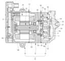
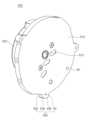
도 1은 종래의 스크롤 압축기를 도시한 단면도이다.1 is a cross-sectional view showing a conventional scroll compressor.
첨부된 도 1을 참조하면, 종래의 스크롤 압축기는, 하우징(10), 상기 하우징(10)의 내부에서 회전력을 발생시키는 모터(20), 상기 모터(20)에 의해 회전되는 회전축(30), 상기 회전축(30)에 의해 선회 운동되는 선회 스크롤(50) 및 상기 선회 스크롤(50)에 치합되어 두 개 한 쌍의 압축실(C)을 형성하는 고정 스크롤(60)을 포함한다.1, a conventional scroll compressor includes a
상기 하우징(10)은 센터 하우징(12), 상기 센터 하우징(12)에 체결되어 상기 모터(20)가 수용되는 제1 공간(S1)을 형성하는 프론트 하우징(14) 및 상기 센터 하우징 경판(12a)을 기준으로 상기 프론트 하우징(14)의 반대측에서 상기 센터 하우징(12)에 체결되어 상기 선회 스크롤(50)과 상기 고정 스크롤(60)이 수용되는 제2 공간(S2)을 형성하는 리어 하우징(16)을 포함한다.The
상기 센터 하우징(12)은 상기 선회 스크롤(50)을 지지하는 센터 하우징 경판(12a) 및 상기 센터 하우징 경판(12a)의 외주부로부터 상기 프론트 하우징(14) 측으로 돌출되는 센터 하우징 측판(12b)을 포함한다.The
상기 센터 하우징 경판(12a)의 중심 측에는 상기 회전축(30)의 일단부가 관통한다.One end of the rotating
상기 프론트 하우징(14)은 상기 센터 하우징 경판(12a)에 대향되고 상기 회전축(30)의 타단부를 지지하는 프론트 하우징 경판(14a) 및 상기 프론트 하우징 경판(14a)의 외주부로부터 돌출되고 상기 센터 하우징 측판(12b)과 체결되며 상기 모터(20)를 지지하는 프론트 하우징 측판(14b)을 포함한다.The
여기서, 상기 센터 하우징 경판(12a), 상기 센터 하우징 측판(12b), 상기 프론트 하우징 경판(14a) 및 상기 프론트 하우징 측판(14b)이 상기 제1 공간(S1)을 형성하는데, 상기 센터 하우징(12)과 상기 프론트 하우징(14)이 각각 별도로 형성된 후 서로 체결되는 것은 상기 모터(20)가 상기 제1 공간(S1)에 삽입 가능하게 하기 위함이다. 이때, 상기 센터 하우징(12)과 상기 프론트 하우징(14) 사이에서 누설이 발생될 수 있으므로, 상기 프론트 하우징 측판(14b)과 상기 센터 하우징 측판(12b) 사이에는 상기 제1 공간(S1)을 상기 하우징(10)의 외부로부터 밀봉시키는 제1 실링부재(70)가 개재된다.Here, the center
상기 리어 하우징(16)은 상기 센터 하우징 경판(12a)에 대향되는 리어 하우징 경판(16a) 및 상기 리어 하우징 경판(16a)의 외주부로부터 돌출되고 상기 센터 하우징 경판(12a)의 외주부에 체결되는 리어 하우징 측판(16b)을 포함한다.The
그리고, 상기 리어 하우징(16)은 상기 압축실(C)로부터 토출되는 냉매를 수용하는 토출실(D)을 더 포함한다.And, the
여기서, 상기 센터 하우징 경판(12a), 상기 리어 하우징 경판(16a) 및 상기 리어 하우징 측판(16b)은 상기 제2 공간(S2)을 형성하는데, 상기 센터 하우징(12)과 상기 리어 하우징(16)이 각각 별도로 형성된 후 서로 체결되는 것은 상기 선회 스크롤(50)과 상기 고정 스크롤(60)이 상기 제2 공간(S2)에 삽입 가능하게 하기 위함이다. 이때, 상기 센터 하우징(12)과 상기 리어 하우징(16) 사이에서 누설이 발생될 수 있으므로, 상기 센터 하우징 경판(12a)과 상기 리어 하우징 측판(16b) 사이에는 상기 제2 공간(S2)을 상기 하우징(10)의 외부로부터 밀봉시키는 제2 실링부재(80)가 개재된다.Here, the center
상기 모터(20)는 상기 프론트 하우징 측판(14b)에 고정되는 고정자 및 상기 고정자의 내부에서 상기 고정자와의 상호 작용으로 회전되는 회전자를 포함한다.The
상기 회전축(30)은 상기 회전자에 체결되되 상기 회전자의 중심부를 관통하여, 상기 회전축(30)의 일단부가 상기 센터 하우징 경판(12a)을 관통하고 상기 선회 스크롤(50)을 선회 운동 시키기 위한 편심부시(40)와 체결되고, 상기 회전축(30)의 타단부가 상기 프론트 하우징 경판(14a)에 지지된다.The rotating
상기 선회 스크롤(50)은 원판형의 선회 스크롤 경판(52), 상기 선회 스크롤 경판(52)의 중심부로부터 상기 고정 스크롤(60) 측으로 돌출되는 선회 스크롤 랩(54) 및 상기 선회 스크롤 경판(52)으로부터 상기 선회 스크롤 랩(54)의 반대측으로 돌출되고 상기 편심부시(40)와 체결되는 선회 스크롤 보스(530)를 포함한다.The orbiting
상기 고정 스크롤(60)은 원판형의 고정 스크롤 경판(62), 상기 고정 스크롤 경판(62)의 중심부로부터 돌출되고 상기 선회 스크롤 랩(54)과 치합되는 고정 스크롤 랩(64) 및 상기 고정 스크롤 경판(62)의 외주부로부터 돌출되고 상기 센터 하우징 경판(12a)과 체결되는 고정 스크롤 측판(66)을 포함한다.The
여기서, 상기 압축실(C)에서 발생되는 소음이 상기 하우징(10)의 외부로 방사되는 것이 방지되도록, 상기 선회 스크롤(50)과 상기 고정 스크롤(60)은 상기 하우징(10)의 내부에 수용되고, 상기 센터 하우징 경판(12a), 상기 고정 스크롤 경판(62) 및 상기 고정 스크롤 측판(66)은 상기 선회 스크롤(50)의 선회 공간을 형성하고, 상기 고정 스크롤 측판(66)은 상기 리어 하우징 측판(16b)과 상기 선회 스크롤(50) 사이에 개재된다.Here, the
그러나, 이러한 종래의 스크롤 압축기는 선회 스크롤(50)과 고정 스크롤(60)이 하우징(10)의 내부에 수용되는 상태에서 냉매 토출량을 증가시키는데 어려움이 있었다. 구체적으로, 냉매 토출량 증가를 위해서는 상기 선회 스크롤(50)의 선회 반경이 증가되거나 상기 압축실(C)의 축 방향 높이가 증가되어야 한다. 하지만, 상기 리어 하우징 측판(16b)과 상기 선회 스크롤(50) 사이에 상기 고정 스크롤 측판(66)이 형성됨에 따라 사전에 결정된 크기를 갖는 하우징(10)의 내부에서 상기 선회 스크롤(50)의 선회 반경이 증가되기 어렵다. 특히, 상기 고정 스크롤 측판(66)은 상기 고정 스크롤(60)을 상기 센터 하우징 경판(12a)에 체결 시키기 위한 체결부재(미도시)가 관통하는 체결홀(미도시)을 포함하고 상기 체결홀(미도시)에 의한 상기 고정 스크롤 측판(66)의 강성 저하를 방지하도록 상기 리어 하우징 측판(16b)보다도 더 두껍게 형성됨에 따라, 상기 선회 스크롤(50)의 선회 반경이 증가되기 더 어렵다. 그리고, 상기 선회 스크롤 경판(52)과 상기 고정 스크롤 경판(62) 사이 거리가 증가되고, 상기 선회 스크롤 랩(54)의 높이와 상기 고정 스크롤 랩(64)의 높이가 증가될 경우, 상기 선회 스크롤(50)과 상기 고정 스크롤(60)의 내구성이 현저히 저하되므로, 상기 압축실(C)의 축 방향 높이가 증가되기도 어렵다.However, in the conventional scroll compressor, it is difficult to increase the refrigerant discharge amount while the orbiting
따라서, 본 발명은, 선회 스크롤과 고정 스크롤이 케이싱의 내부에 수용되는 상태에서 냉매 토출량을 증가시킬 수 있는 스크롤 압축기를 제공하는 것을 그 목적으로 한다.Accordingly, an object of the present invention is to provide a scroll compressor capable of increasing a refrigerant discharge amount in a state where an orbiting scroll and a fixed scroll are accommodated in a casing.
본 발명은, 상기한 바와 같은 목적 달성을 위해, 케이싱; 상기 케이싱의 내부에서 회전력을 발생시키는 모터; 상기 모터에 의해 회전되는 회전축; 상기 회전축에 의해 선회 운동되는 선회 스크롤; 상기 선회 스크롤에 치합되어 두 개 한 쌍의 압축실을 형성하는 고정 스크롤; 및 상기 선회 스크롤을 지지하는 메인 프레임;을 포함하고, 상기 고정 스크롤은 고정 스크롤 경판 및 상기 고정 스크롤 경판으로부터 돌출되는 고정 스크롤 랩을 포함하고, 상기 메인 프레임은 상기 선회 스크롤을 기준으로 상기 고정 스크롤 경판의 반대측에 구비되는 메인 프레임 경판을 포함하고, 상기 고정 스크롤 경판, 상기 메인 프레임 경판 및 상기 케이싱이 상기 선회 스크롤의 선회 공간을 형성하는 스크롤 압축기를 제공한다.The present invention, to achieve the object as described above, the casing; a motor generating rotational force inside the casing; a rotation shaft rotated by the motor; an orbiting scroll that is pivotally moved by the rotation shaft; a fixed scroll meshed with the orbiting scroll to form two pairs of compression chambers; and a main frame supporting the orbiting scroll, wherein the fixed scroll includes a fixed scroll head plate and a fixed scroll wrap protruding from the fixed scroll head plate, wherein the main frame is the fixed scroll head plate based on the orbiting scroll. A main frame head plate provided on the opposite side of the scroll compressor, wherein the fixed scroll head plate, the main frame head plate, and the casing form a turning space of the orbiting scroll.
상기 고정 스크롤 랩은 상기 케이싱에 대향되게 형성될 수 있다.The fixed scroll wrap may be formed to face the casing.
상기 고정 스크롤은 상기 고정 스크롤 경판의 외주면으로부터 반경방향으로 돌출되고 상기 케이싱에 체결되는 고정 스크롤 플랜지를 더 포함할 수 있다.The fixed scroll may further include a fixed scroll flange protruding radially from an outer circumferential surface of the fixed scroll head plate and fastened to the casing.
상기 메인 프레임은 상기 메인 프레임 경판의 외주면으로부터 반경방향으로 돌출되고 상기 케이싱에 체결되는 메인 프레임 플랜지를 더 포함할 수 있다.The main frame may further include a main frame flange protruding in a radial direction from an outer circumferential surface of the main frame head plate and fastened to the casing.
상기 케이싱은, 상기 모터, 상기 회전축, 상기 선회 스크롤, 상기 고정 스크롤 및 상기 메인 프레임이 수용되는 수용공간을 갖는 제1 케이싱; 및 상기 제1 케이싱에 체결되며 상기 수용공간을 복개하는 제2 케이싱;을 포함할 수 있다.The casing may include: a first casing having an accommodating space in which the motor, the rotating shaft, the orbiting scroll, the fixed scroll, and the main frame are accommodated; and a second casing fastened to the first casing and covering the accommodation space.
상기 제1 케이싱은, 상기 회전축의 일단부를 지지하는 제1 케이싱 경판; 및 상기 제1 케이싱 경판의 외주부로부터 상기 제2 케이싱 측으로 돌출되고 상기 모터, 상기 메인 프레임 및 상기 고정 스크롤을 지지하는 제1 케이싱 측판;을 포함할 수 있다.The first casing may include a first casing end plate supporting one end of the rotating shaft; and a first casing side plate protruding toward the second casing from an outer circumference of the first casing end plate and supporting the motor, the main frame, and the fixed scroll.
상기 제1 케이싱 측판은, 상기 메인 프레임 플랜지가 삽입되는 제1 플랜지 삽입홈; 및 상기 고정 스크롤 플랜지가 삽입되는 제2 플랜지 삽입홈;을 포함할 수 있다.The first casing side plate includes a first flange insertion groove into which the main frame flange is inserted; and a second flange insertion groove into which the fixed scroll flange is inserted.
상기 제1 플랜지 삽입홈은, 상기 제1 케이싱 측판의 내주면으로부터 절곡된 제1 플랜지 삽입홈 기저면; 및 상기 제1 플랜지 삽입홈 기저면으로부터 절곡되고 상기 제1 케이싱 측판의 선단면까지 연장되는 제1 플랜지 삽입홈 내주면;을 포함할 수 있다.The first flange insertion groove, the base surface of the first flange insertion groove bent from the inner peripheral surface of the first casing side plate; and an inner circumferential surface of the first flange insertion groove that is bent from the base surface of the first flange insertion groove and extends to the front end surface of the first casing side plate.
상기 메인 프레임 플랜지는, 상기 제1 플랜지 삽입홈 기저면에 접촉되는 메인 프레임 플랜지 기저면; 상기 메인 프레임 플랜지 기저면으로부터 절곡되고 상기 제1 플랜지 삽입홈 내주면에 대향되는 메인 프레임 플랜지 외주면; 및 상기 메인 프레임 플랜지 외주면으로부터 절곡되고 상기 메인 프레임 플랜지 기저면의 배면을 이루는 메인 프레임 플랜지 상면;을 포함할 수 있다.The main frame flange may include a main frame flange base surface contacting a base surface of the first flange insertion groove; an outer circumferential surface of the main frame flange bent from the base surface of the main frame flange and opposed to an inner circumferential surface of the first flange insertion groove; and an upper surface of the main frame flange bent from an outer circumferential surface of the main frame flange and forming a rear surface of the base surface of the main frame flange.
상기 메인 프레임 플랜지는 상기 메인 프레임 플랜지 상면으로부터 상기 메인 프레임 플랜지 기저면까지 상기 메인 프레임 플랜지를 관통하는 제1 체결홀을 포함하고, 상기 제1 플랜지 삽입홈은 상기 제1 플랜지 삽입홈 기저면으로부터 음각지게 형성되는 제2 체결홀을 포함하고, 상기 메인 프레임 플랜지는 상기 제1 체결홀 및 상기 제2 체결홀에 삽입되는 제1 체결부재에 의해 상기 제1 케이싱 측판에 체결될 수 있다.The main frame flange includes a first fastening hole penetrating the main frame flange from an upper surface of the main frame flange to a bottom surface of the main frame flange, and the first flange insertion groove is formed to be intaglio from the base surface of the first flange insertion groove. and a second fastening hole, and the main frame flange may be fastened to the first casing side plate by a first fastening member inserted into the first fastening hole and the second fastening hole.
상기 제2 플랜지 삽입홈은, 상기 제1 케이싱 측판의 내주면으로부터 절곡된 제2 플랜지 삽입홈 기저면; 및 상기 제2 플랜지 삽입홈 기저면으로부터 절곡되고 상기 제1 케이싱 측판의 선단면까지 연장되는 제2 플랜지 삽입홈 내주면;을 포함할 수 있다.The second flange insertion groove, the base surface of the second flange insertion groove bent from the inner peripheral surface of the first casing side plate; and an inner circumferential surface of the second flange insertion groove that is bent from the base surface of the second flange insertion groove and extends to the front end surface of the first casing side plate.
상기 고정 스크롤 플랜지는, 상기 제2 플랜지 삽입홈 기저면에 접촉되는 고정 스크롤 플랜지 기저면; 상기 고정 스크롤 플랜지 기저면으로부터 절곡되고 상기 제2 플랜지 삽입홈 내주면에 대향되는 고정 스크롤 플랜지 외주면; 및 상기 고정 스크롤 플랜지 외주면으로부터 절곡되고 상기 고정 스크롤 플랜지 기저면의 배면을 이루는 고정 스크롤 플랜지 상면;을 포함할 수 있다.The fixed scroll flange may include a bottom surface of the fixed scroll flange in contact with the bottom surface of the second flange insertion groove; an outer circumferential surface of the fixed scroll flange bent from the base surface of the fixed scroll flange and facing the inner circumferential surface of the second flange insertion groove; and an upper surface of the fixed scroll flange bent from an outer circumferential surface of the fixed scroll flange and forming a rear surface of the base surface of the fixed scroll flange.
상기 고정 스크롤 플랜지는 상기 고정 스크롤 플랜지 상면으로부터 상기 고정 스크롤 플랜지 기저면까지 상기 고정 스크롤 플랜지를 관통하는 제3 체결홀을 포함하고, 상기 제2 플랜지 삽입홈은 상기 제2 플랜지 삽입홈 기저면으로부터 음각지게 형성되는 제4 체결홀을 포함하고, 상기 고정 스크롤 플랜지는 상기 제3 체결홀 및 상기 제4 체결홀에 삽입되는 제2 체결부재에 의해 상기 제1 케이싱 측판에 체결될 수 있다.The fixed scroll flange includes a third fastening hole penetrating the fixed scroll flange from an upper surface of the fixed scroll flange to a bottom surface of the fixed scroll flange, and the second flange insertion groove is formed to be engraved from the base surface of the second flange insertion groove. and a fourth fastening hole, and the fixed scroll flange may be fastened to the first casing side plate by a second fastening member inserted into the third fastening hole and the fourth fastening hole.
상기 모터, 상기 회전축, 상기 선회 스크롤, 상기 고정 스크롤 및 상기 메인 프레임은 상기 제2 케이싱 측으로부터 상기 제1 케이싱 측으로 삽입되어 상기 수용공간에 수용될 수 있다.The motor, the rotating shaft, the orbiting scroll, the fixed scroll, and the main frame may be inserted into the first casing from the second casing side and accommodated in the accommodating space.
상기 제1 케이싱과 상기 제2 케이싱 사이에는 상기 수용공간을 상기 케이싱의 외부로부터 밀봉시키는 실링부재가 형성되고, 상기 수용공간은 상기 실링부재에 의해서만 밀봉될 수 있다.A sealing member sealing the accommodating space from the outside of the casing is formed between the first casing and the second casing, and the accommodating space can be sealed only by the sealing member.
본 발명에 의한 스크롤 압축기는, 케이싱; 상기 케이싱의 내부에서 회전력을 발생시키는 모터; 상기 모터에 의해 회전되는 회전축; 상기 회전축에 의해 선회 운동되는 선회 스크롤; 상기 선회 스크롤에 치합되어 두 개 한 쌍의 압축실을 형성하는 고정 스크롤; 및 상기 선회 스크롤을 지지하는 메인 프레임;을 포함하고, 상기 고정 스크롤은 고정 스크롤 경판 및 상기 고정 스크롤 경판으로부터 돌출되는 고정 스크롤 랩을 포함하고, 상기 메인 프레임은 상기 선회 스크롤을 기준으로 상기 고정 스크롤 경판의 반대측에 구비되는 메인 프레임 경판을 포함하고, 상기 고정 스크롤 경판, 상기 메인 프레임 경판 및 상기 케이싱이 상기 선회 스크롤의 선회 공간을 형성함에 따라, 사전에 결정된 크기를 갖는 케이싱의 내부에서 상기 선회 스크롤의 선회 반경을 증가시켜, 선회 스크롤과 고정 스크롤이 케이싱의 내부에 수용되는 상태에서 냉매 토출량을 증가시킬 수 있다.A scroll compressor according to the present invention includes a casing; a motor generating rotational force inside the casing; a rotation shaft rotated by the motor; an orbiting scroll that is pivotally moved by the rotation shaft; a fixed scroll meshed with the orbiting scroll to form two pairs of compression chambers; and a main frame supporting the orbiting scroll, wherein the fixed scroll includes a fixed scroll head plate and a fixed scroll wrap protruding from the fixed scroll head plate, wherein the main frame is the fixed scroll head plate based on the orbiting scroll. and a main frame head plate provided on the opposite side of the orbiting scroll inside the casing having a predetermined size as the fixed scroll head plate, the main frame head plate, and the casing form a orbiting space of the orbiting scroll. By increasing the turning radius, it is possible to increase the refrigerant discharge amount in a state where the orbiting scroll and the fixed scroll are accommodated in the casing.
도 1은 종래의 스크롤 압축기를 도시한 단면도,
도 2는 본 발명의 일 실시예에 따른 스크롤 압축기를 도시한 단면도,
도 3은 도 2의 A부분 확대도,
도 4는 도 2의 스크롤 압축기를 다른 방향으로 절개하여 도시한 단면도,
도 5는 도 4의 B부분 확대도,
도 6은 도 2의 스크롤 압축기에서 제1 케이싱을 도시한 사시도,
도 7은 도 2의 스크롤 압축기에서 메인 프레임을 도시한 사시도,
도 8은 도 7의 배면을 도시한 사시도,
도 9는 도 2의 스크롤 압축기에서 고정 스크롤을 도시한 사시도,
도 10은 도 9의 배면을 도시한 사시도이다.1 is a cross-sectional view showing a conventional scroll compressor;
2 is a cross-sectional view showing a scroll compressor according to an embodiment of the present invention;
3 is an enlarged view of part A of FIG. 2;
4 is a cross-sectional view of the scroll compressor of FIG. 2 cut in another direction;
5 is an enlarged view of part B of FIG. 4;
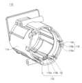
6 is a perspective view showing a first casing in the scroll compressor of FIG. 2;
7 is a perspective view showing a main frame in the scroll compressor of FIG. 2;
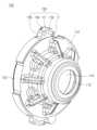
Figure 8 is a perspective view showing the rear of Figure 7;
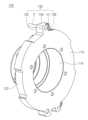
9 is a perspective view showing a fixed scroll in the scroll compressor of FIG. 2;
Figure 10 is a perspective view showing the rear of Figure 9;
이하, 본 발명에 의한 스크롤 압축기를 첨부된 도면을 참조하여 상세히 설명한다.Hereinafter, a scroll compressor according to the present invention will be described in detail with reference to the accompanying drawings.
도 2는 본 발명의 일 실시예에 따른 스크롤 압축기를 도시한 단면도이고, 도 3은 도 2의 A부분 확대도이고, 도 4는 도 2의 스크롤 압축기를 다른 방향으로 절개하여 도시한 단면도이고, 도 5는 도 4의 B부분 확대도이고, 도 6은 도 2의 스크롤 압축기에서 제1 케이싱을 도시한 사시도이고, 도 7은 도 2의 스크롤 압축기에서 메인 프레임을 도시한 사시도이고, 도 8은 도 7의 배면을 도시한 사시도이고, 도 9는 도 2의 스크롤 압축기에서 고정 스크롤을 도시한 사시도이며, 도 10은 도 9의 배면을 도시한 사시도이다.2 is a cross-sectional view showing a scroll compressor according to an embodiment of the present invention, FIG. 3 is an enlarged view of part A of FIG. 2, and FIG. 4 is a cross-sectional view of the scroll compressor of FIG. 2 cut in another direction, Figure 5 is an enlarged view of part B of Figure 4, Figure 6 is a perspective view showing a first casing in the scroll compressor of Figure 2, Figure 7 is a perspective view showing the main frame in the scroll compressor of Figure 2, Figure 8 FIG. 7 is a perspective view showing the rear side, FIG. 9 is a perspective view showing a fixed scroll in the scroll compressor of FIG. 2, and FIG. 10 is a perspective view showing the rear side of FIG.
첨부된 도 2 내지 도 10을 참조하면, 본 발명의 일 실시예에 따른 스크롤 압축기는, 케이싱(100), 상기 케이싱(100)의 내부에서 회전력을 발생시키는 모터(200), 상기 모터(200)에 의해 회전되는 회전축(300), 상기 회전축(300)에 의해 선회 운동되는 선회 스크롤(500), 상기 선회 스크롤(500)에 치합되어 두 개 한 쌍의 압축실(C)을 형성하는 고정 스크롤(600) 및 상기 선회 스크롤(500)을 지지하는 메인 프레임(700)을 포함할 수 있다.2 to 10, the scroll compressor according to an embodiment of the present invention includes a
상기 케이싱(100)은 상기 모터(200), 상기 회전축(300), 상기 선회 스크롤(500), 상기 고정 스크롤(600) 및 상기 메인 프레임(700)이 수용되는 수용공간(S)을 갖는 제1 케이싱(110) 및 상기 제1 케이싱(110)에 체결되며 상기 수용공간(S)을 복개하는 제2 케이싱(120)을 포함할 수 있다.The
상기 제1 케이싱(110)은 상기 회전축(300)의 일단부를 지지하는 제1 케이싱 경판(112) 및 상기 제1 케이싱 경판(112)의 외주부로부터 상기 제2 케이싱(120) 측으로 돌출되고 상기 모터(200), 상기 메인 프레임(700) 및 상기 고정 스크롤(600)을 지지하는 제1 케이싱 측판(114)을 포함할 수 있다.The
상기 제1 케이싱 경판(112)은 대략 원판형으로 형성되고, 상기 제1 케이싱 경판(112)의 중심측에 상기 회전축(300)의 일단부가 삽입되는 회전축 지지홈을 포함할 수 있다.The first
상기 제1 케이싱 측판(114)은 대략 환형으로 형성되고, 외부로부터 상기 수용공간(S)(더욱 정확히는, 후술할 제1 공간(S1))으로 냉매를 안내하는 냉매흡입관(미도시)과 연통되는 흡입포트(미도시)를 포함할 수 있다.The first
그리고, 상기 제1 케이싱 측판(114)은 후술할 메인 프레임 플랜지(730)가 삽입되도록 상기 제1 케이싱 측판(114)의 선단면 및 상기 제1 케이싱 측판(114)의 내주면으로부터 음각지게 형성되는 제1 플랜지 삽입홈(116) 및 후술할 고정 스크롤 플랜지(630)가 삽입되도록 상기 제1 케이싱 측판(114)의 선단면 및 상기 제1 케이싱 측판(114)의 내주면으로부터 음각지게 형성되는 제2 플랜지 삽입홈(118)을 포함할 수 있다.In addition, the first
상기 제1 플랜지 삽입홈(116)은 상기 제1 케이싱 측판(114)의 내주면으로부터 절곡된 제1 플랜지 삽입홈 기저면(116a) 및 상기 제1 플랜지 삽입홈 기저면(116a)으로부터 절곡되고 상기 제1 케이싱 측판(114)의 선단면까지 연장되는 제1 플랜지 삽입홈 내주면(116b)을 포함할 수 있다.The first
그리고, 상기 제1 플랜지 삽입홈(116)은 후술할 제1 체결부재(810)가 삽입되도록 상기 제1 플랜지 삽입홈 기저면(116a)으로부터 음각지게 형성되는 제2 체결홀(H2)을 포함할 수 있다.In addition, the first
상기 제2 플랜지 삽입홈(118)은 상기 제1 케이싱 측판(114)의 내주면으로부터 절곡된 제2 플랜지 삽입홈 기저면(118a) 및 상기 제2 플랜지 삽입홈 기저면(118a)으로부터 절곡되고 상기 제1 케이싱 측판(114)의 선단면까지 연장되는 제2 플랜지 삽입홈 내주면(118b)을 포함할 수 있다.The second flange insertion groove 118 is bent from the second flange insertion
그리고, 상기 제2 플랜지 삽입홈(118)은 후술할 제2 체결부재(820)가 삽입되도록 상기 제2 플랜지 삽입홈 기저면(118a)으로부터 음각지게 형성되는 제4 체결홀(H4)을 포함할 수 있다.Further, the second flange insertion groove 118 may include a fourth fastening hole H4 formed in an intaglio from the second flange insertion
그리고, 상기 제1 플랜지 삽입홈(116)은 후술할 위치결정핀(P)이 삽입되도록 상기 제1 플랜지 삽입홈 기저면(116a)으로부터 음각지게 형성되는 핀 삽입홈(G)을 포함할 수 있다.In addition, the first
상기 제2 케이싱(120)은 상기 고정 스크롤(600)에 대향되는 제2 케이싱 경판(122) 및 상기 제2 케이싱 경판(122)의 외주부로부터 돌출되고 상기 제1 케이싱 측판(114)에 체결되는 제2 케이싱 측판(124)을 포함할 수 있다.The
상기 제2 케이싱 경판(122)은 상기 압축실(C)로부터 토출되는 냉매를 수용하는 토출실(D)을 포함할 수 있다.The second
그리고, 상기 제2 케이싱 경판(122)은 상기 토출실(D)의 냉매를 외부로 안내하는 냉매토출관(미도시)과 연통되는 토출포트(미도시)를 포함할 수 있다.Further, the second
상기 제2 케이싱 측판(124)은 상기 제1 케이싱 측판(114)에 체결 가능하도록, 그리고 후술할 고정 스크롤 플랜지(630)가 상기 제2 플랜지 삽입홈(118)으로부터 이탈되는 것을 방지하도록, 상기 제2 케이싱 측판(124)의 선단면이 상기 제1 케이싱 측판(114)의 선단면 및 후술할 고정 스크롤 플랜지 상면(636)에 대향되게 형성될 수 있다. 즉, 상기 제2 케이싱 측판(124)의 외경이 상기 제1 케이싱 측판(114)의 외경과 동등 수준으로 형성되고, 상기 제2 케이싱 측판(124)의 내경이 상기 제2 플랜지 삽입홈(118)의 내경보다 작게 형성될 수 있다.The second
여기서, 상기 제1 케이싱(110)은 일체로 형성되는데, 상기 메인 프레임(700)이 상기 제1 케이싱(110)에 탈착 가능하게 형성됨에 따라 상기 제1 케이싱(110)이 일체로 형성되어도 상기 모터(200), 상기 회전축(300), 상기 선회 스크롤(500) 및 상기 고정 스크롤(600)이 상기 제2 케이싱(120) 측으로부터 상기 제1 케이싱(110) 측으로 삽입되어 상기 수용공간(S)에 수용될 수 있다. 즉, 상기 모터(200)와 상기 회전축(300)이 상기 수용공간(S)에 먼저 삽입될 수 있다. 그 다음, 상기 메인 프레임(700)이 상기 수용공간(S)에 삽입되면서 상기 수용공간(S)을 상기 모터(200)가 수용되는 제1 공간(S1)과 상기 선회 스크롤(500) 및 상기 고정 스크롤(600)이 수용되는 제2 공간(S2)으로 구획할 수 있다. 그 다음, 상기 선회 스크롤(500)을 선회 운동시키기 위한 편심부시(400)가 상기 수용공간(S)(더욱 정확히는, 제2 공간(S2))으로 삽입되어 상기 회전축(300)에 체결되고, 상기 선회 스크롤(500)이 상기 수용공간(S)(더욱 정확히는, 제2 공간(S2))으로 삽입되어 상기 편심부시(400)에 체결될 수 있다. 그 다음, 상기 고정 스크롤(600)이 상기 수용공간(S)(더욱 정확히는, 제2 공간(S2))으로 삽입될 수 있다. 그 다음, 상기 제2 케이싱(120)이 상기 제1 케이싱(110)에 체결되어 상기 수용공간(S)을 복개할 수 있다.Here, the
한편, 상기 제1 케이싱 측판(114)의 선단면과 상기 제2 케이싱 측판(124)의 선단면 사이에서 누설이 발생될 수 있으므로, 이를 방지하기 위해 상기 제1 케이싱 측판(114)의 선단면과 상기 제2 케이싱 측판(124)의 선단면 사이에는 상기 수용공간(S)을 상기 케이싱(100)의 외부로부터 밀봉시키는 실링부재(900)가 형성될 수 있다.On the other hand, since leakage may occur between the front end surface of the first
상기 모터(200)는 상기 제1 케이싱 측판(114)에 고정되는 고정자 및 상기 고정자의 내부에서 상기 고정자와의 상호 작용으로 회전되는 회전자를 포함할 수 있다.The
상기 회전축(300)은 상기 회전자에 체결되되 상기 회전자의 중심부를 관통하여 상기 회전축(300)의 일단부가 상기 메인 프레임(700)을 관통하고 상기 회전축(300)의 타단부가 상기 제1 케이싱 경판(112)에 지지될 수 있다.The
상기 선회 스크롤(500)은 원판형의 선회 스크롤 경판(510), 상기 선회 스크롤 경판(510)의 중심부로부터 상기 고정 스크롤(600) 측으로 돌출되는 선회 스크롤 랩(520) 및 상기 선회 스크롤 경판(510)의 중심부로부터 상기 선회 스크롤 랩(520)의 반대측으로 돌출되고 상기 편심부시(400)와 체결되는 선회 스크롤 보스(530)를 포함할 수 있다.The
상기 고정 스크롤(600)은 원판형의 고정 스크롤 경판(610), 상기 고정 스크롤 경판(610)의 중심부로부터 돌출되고 상기 선회 스크롤 랩(520)과 치합되는 고정 스크롤 랩(620) 및 상기 고정 스크롤 경판(610)의 외주면으로부터 반경방향으로 돌출되고 상기 제1 케이싱(110)의 제2 플랜지 삽입홈(118)에 삽입되는 고정 스크롤 플랜지(630)를 포함할 수 있다.The fixed
여기서, 상기 고정 스크롤 경판(610), 상기 고정 스크롤 랩(620) 및 상기 고정 스크롤 플랜지(630)는 상기 고정 스크롤(600)의 외관을 형성할 수 있다.Here, the fixed
상기 고정 스크롤 경판(610)의 중심측에는 상기 압축실(C)의 냉매를 상기 토출실(D)로 토출하는 토출공(612)이 형성될 수 있다.A
상기 고정 스크롤 플랜지(630)는 상기 고정 스크롤(600)을 상기 제1 케이싱(110)에 체결시키기 위한 것으로서, 상기 제2 플랜지 삽입홈(118)에 삽입된 상태에서 상기 제1 케이싱(110)에 체결되도록 형성될 수 있다.The fixed
구체적으로, 상기 고정 스크롤 플랜지(630)는 상기 제2 플랜지 삽입홈 기저면(118a)에 접촉되는 고정 스크롤 플랜지 기저면(632), 상기 고정 스크롤 플랜지 기저면(632)으로부터 절곡되고 상기 제2 플랜지 삽입홈 내주면(118b)에 대향되는 고정 스크롤 플랜지 외주면(634), 상기 고정 스크롤 플랜지 외주면(634)으로부터 절곡되고 상기 고정 스크롤 플랜지 기저면(632)의 배면을 이루는 고정 스크롤 플랜지 상면(636) 및 상기 고정 스크롤 플랜지 상면(636)으로부터 상기 고정 스크롤 플랜지 기저면(632)까지 상기 고정 스크롤 플랜지(630)를 관통하는 제3 체결홀(H3)을 포함할 수 있다.Specifically, the fixed
여기서, 상기 고정 스크롤 플랜지(630)는 상기 제3 체결홀(H3) 및 상기 제4 체결홀(H4)에 삽입되는 제2 체결부재(820)에 의해 상기 제1 케이싱 측판(114)에 체결될 수 있다.Here, the fixed
상기 메인 프레임(700)은 상기 선회 스크롤(500)을 기준으로 상기 고정 스크롤 경판(610)의 반대측에 구비되는 메인 프레임 경판(710) 및 상기 메인 프레임 경판(710)의 외주면으로부터 반경방향으로 돌출되고 상기 제1 케이싱(110)의 제1 플랜지 삽입홈(116)에 삽입되는 메인 프레임 플랜지(730)를 포함할 수 있다.The
여기서, 상기 메인 프레임 경판(710) 및 상기 메인 프레임 플랜지(730)는 상기 메인 프레임(700)의 외관을 형성할 수 있다.Here, the main
상기 메인 프레임 경판(710)에는 상기 회전축(300)의 일단부가 관통하는 축수공(712) 및 상기 회전축(300)의 일단부에 체결되는 상기 편심부시(400)가 회전될 수 있는 공간을 제공하며 상기 선회 스크롤(500)을 상기 고정 스크롤(600) 측으로 가압하는 배압실(714)이 형성될 수 있다.The main
그리고, 상기 메인 프레임 경판(710)의 모터 대향면에는 상기 메인 프레임 경판(710)의 강성을 향상시키기 위한 방사형의 보강리브(716)가 형성될 수 있다.In addition, a radial reinforcing rib 716 may be formed on a surface of the main
그리고, 상기 메인 프레임 경판(710)의 외주부에는 상기 냉매흡입관(미도시)을 통해 상기 제1 공간(S1)으로 유입된 냉매를 상기 압축실(C)로 안내하도록 상기 메인 프레임 경판(710)을 관통하여 상기 제1 공간(S1)과 상기 제2 공간(S2)을 연통시키는 흡입공(722)이 형성될 수 있다.In addition, the main
상기 메인 프레임 플랜지(730)는 상기 메인 프레임(700)을 상기 제1 케이싱(110)에 체결시키기 위한 것으로서, 상기 제1 플랜지 삽입홈(116)에 삽입된 상태에서 상기 제1 케이싱(110)에 체결되도록 형성될 수 있다.The
구체적으로, 상기 메인 프레임 플랜지(730)는 상기 제1 플랜지 삽입홈 기저면(116a)에 접촉되는 메인 프레임 플랜지 기저면(732), 상기 메인 프레임(700) 기저면으로부터 절곡되고 상기 제1 플랜지 삽입홈 내주면(116b)에 대향되는 메인 프레임 플랜지 외주면(734), 상기 메인 프레임 플랜지 외주면(734)으로부터 절곡되고 상기 메인 프레임 플랜지 기저면(732)의 배면을 이루는 메인 프레임 플랜지 상면(736) 및 상기 메인 프레임 플랜지 상면(736)으로부터 상기 메인 프레임 플랜지 기저면(732)까지 상기 메인 프레임 플랜지(730)를 관통하는 제1 체결홀(H1)을 포함할 수 있다.Specifically, the
여기서, 상기 메인 프레임 플랜지(730)는 상기 제1 체결홀(H1) 및 상기 제2 체결홀(H2)에 삽입되는 제1 체결부재(810)에 의해 상기 제1 케이싱 측판(114)에 체결될 수 있다.Here, the
그리고, 상기 메인 프레임 플랜지(730)는 상기 제1 플랜지 삽입홈(116)에 삽입될 때 상기 제1 체결홀(H1)과 상기 제2 체결홀(H2)이 정렬되도록, 즉 상기 메인 프레임 플랜지(730)의 위치를 사전에 결정된 위치로 포지셔닝되도록 상기 핀 삽입홈(G)에 삽입되는 위치결정핀(P)을 더 포함할 수 있다.In addition, when the
상기 위치결정핀(P)은 상기 메인 프레임 플랜지(730)와 일체로 형성될 수도 있고, 상기 메인 프레임 플랜지(730)에 탈착 가능하게 형성될 수도 있다.The positioning pin P may be integrally formed with the
이하, 본 실시예에 따른 스크롤 압축기의 작용효과에 대해 설명한다.Hereinafter, operational effects of the scroll compressor according to the present embodiment will be described.
즉, 상기 모터(200)에 전원이 인가되면 상기 회전축(300)이 상기 회전자와 함께 회전될 수 있다.That is, when power is applied to the
그리고, 상기 선회 스크롤(500)이 상기 편심부시(400)를 통해 상기 회전축(300)으로부터 회전력을 전달받아 선회 운동될 수 있다.In addition, the
이에 따라, 상기 압축실(C)은 중심측을 향해 지속적으로 이동되면서 체적이 감소될 수 있다.Accordingly, the compression chamber (C) can be reduced in volume while continuously moving toward the center side.
그리고, 냉매는 상기 냉매흡입관(미도시), 상기 제1 공간(S1), 상기 흡입공(722)을 통해 상기 제2 공간(S2)으로 유입될 수 있다.The refrigerant may be introduced into the second space S2 through the refrigerant suction pipe (not shown), the first space S1, and the
그리고, 상기 제2 공간(S2)으로 유입된 냉매는 상기 압축실(C)로 흡입될 수 있다.And, the refrigerant introduced into the second space (S2) may be sucked into the compression chamber (C).
그리고, 상기 압축실(C)로 흡입된 냉매는 상기 압축실(C)의 이동경로를 따라 중심측으로 이동되면서 압축되어 상기 토출공(612)을 통해 상기 토출실(D)로 토출될 수 있다.In addition, the refrigerant sucked into the compression chamber (C) may be compressed while moving toward the center along the moving path of the compression chamber (C) and discharged to the discharge chamber (D) through the discharge hole (612).
그리고, 상기 토출실(D)로 토출된 냉매는 상기 냉매토출관(미도시)을 통해 압축기의 외부로 배출될 수 있다.Also, the refrigerant discharged into the discharge chamber D may be discharged to the outside of the compressor through the refrigerant discharge pipe (not shown).
여기서, 본 실시예에 따른 스크롤 압축기는, 상기 선회 스크롤(500)과 상기 고정 스크롤(600)이 상기 케이싱(100)의 내부에 수용됨에 따라, 상기 압축실(C)에서 발생되는 소음이 상기 케이싱(100)에 의해 감소될 수 있다. 이에 의하여, 상기 압축실(C)에서 발생되는 소음이 상기 케이싱(100)의 외부로 방사되는 것이 방지될 수 있다.Here, in the scroll compressor according to the present embodiment, as the
그리고, 상기 고정 스크롤 경판(610), 상기 메인 프레임 경판(710) 및 상기 제1 케이싱 측판(114)이 상기 선회 스크롤(500)의 선회 공간을 형성하고, 상기 선회 스크롤(500)이 반경방향 상 상기 제1 케이싱 측판(114)에 대향됨에 따라, 즉, 상기 고정 스크롤 랩(620)이 상기 케이싱(100)에 대향됨에 따라, 상기 선회 스크롤(500)의 선회 반경이 증가될 수 있다. 즉, 상기 선회 스크롤(500)의 선회 반경은 상기 선회 스크롤(500)이 상기 제1 케이싱 측판(114)과 간섭되지 않는 범위 내에서 최대로 형성될 수 있다.In addition, the fixed
이에 의하여, 상기 압축실(C)의 축 방향 높이를 사전에 결정된 수준으로 유지하면서 냉매 토출량이 증가될 수 있다. 즉, 상기 선회 스크롤 랩(520)과 상기 고정 스크롤 랩(620)의 강성을 사전에 결정된 수준으로 유지하면서 냉매 토출량이 증가될 수 있다.As a result, the refrigerant discharge amount can be increased while maintaining the axial height of the compression chamber (C) at a predetermined level. That is, the discharge amount of the refrigerant may be increased while maintaining the rigidity of the
또는, 냉매 토출량을 사전에 결정된 수준으로 유지하면서 상기 제1 케이싱 측판(114)의 외경이 감소될 수 있다. 이에 따라, 스크롤 압축기의 중량 및 원가가 절감될 수 있고, 차량 탑재성이 개선될 수 있다.Alternatively, the outer diameter of the first
한편, 상기 고정 스크롤(600)은 상기 고정 스크롤 경판(610)이 상기 제1 케이싱 측판(114)에 직접 체결되지 않고 상기 고정 스크롤 플랜지(630)를 통해 상기 제1 케이싱 측판(114)에 체결됨에 따라, 상기 고정 스크롤 경판(610)의 두께가 얇게 형성되더라도 상기 고정 스크롤 경판(610)의 강성이 확보될 수 있다. 즉, 상기 고정 스크롤 경판(610)의 강성이 사전에 결정된 수준으로 유지되면서 상기 고정 스크롤 경판(610)의 두께가 감소될 수 있고, 이 경우 스크롤 압축기의 축방향 길이, 원가 및 중량이 감소되고, 차량 탑재성이 개선될 수 있다.Meanwhile, the fixed
이와 유사하게, 상기 메인 프레임(700)은 상기 메인 프레임 경판(710)이 상기 제1 케이싱 측판(114)에 직접 체결되지 않고 상기 메인 프레임 플랜지(730)를 통해 상기 제1 케이싱 측판(114)에 체결됨에 따라, 상기 메인 프레임 경판(710)의 두께가 얇게 형성되더라도 상기 메인 프레임 경판(710)의 강성이 확보될 수 있다. 즉, 상기 메인 프레임 경판(710)의 강성이 사전에 결정된 수준으로 유지되면서 상기 메인 프레임 경판(710)의 두께가 감소될 수 있고, 이 경우 스크롤 압축기의 축방향 길이, 원가 및 중량이 감소되고, 차량 탑재성이 개선될 수 있다.Similarly, in the
한편, 상기 메인 프레임(700)이 상기 케이싱(100)에 탈착 가능하게 형성됨에 따라, 상기 제1 케이싱(110)이 일체로 형성될 수 있다. 이에 따라, 상기 수용공간(S)은 상기 제1 케이싱(110)과 상기 제2 케이싱(120) 사이에 개재되는 상기 실링부재(900)에 의해서만 밀봉되면 충분하므로, 원가가 절감되고, 누설의 위험이 현저히 낮아질 수 있다.Meanwhile, as the
100: 케이싱110: 제1 케이싱
112: 제1 케이싱 경판114: 제1 케이싱 측판
116: 제1 플랜지 삽입홈116a: 제1 플랜지 삽입홈 기저면
116b: 제1 플랜지 삽입홈 내주면118: 제2 플랜지 삽입홈
118a: 제2 플랜지 삽입홈 기저면118b: 제2 플랜지 삽입홈 내주면
120: 제2 케이싱200: 모터
300: 회전축500: 선회 스크롤
600: 고정 스크롤610: 고정 스크롤 경판
620: 고정 스크롤 랩630: 고정 스크롤 플랜지
632: 고정 스크롤 플랜지 기저면634: 고정 스크롤 플랜지 외주면
636: 고정 스크롤 플랜지 상면700: 메인 프레임
710: 메인 프레임 경판730: 메인 프레임 플랜지
732: 메인 프레임 플랜지 기저면734: 메인 프레임 플랜지 외주면
736: 메인 프레임 플랜지 상면810: 제1 체결부재
820: 제2 체결부재900: 실링부재
H1: 제1 체결홀H2: 제2 체결홀
H3: 제3 체결홀H4: 제4 체결홀100: casing 110: first casing
112: first casing end plate 114: first casing side plate
116: first
116b: first flange insertion groove inner circumference 118: second flange insertion groove
118a: second flange insertion
120: second casing 200: motor
300: axis of rotation 500: turning scroll
600: fixed scroll 610: fixed scroll headplate
620: fixed scroll wrap 630: fixed scroll flange
632: fixed scroll flange base surface 634: fixed scroll flange outer circumferential surface
636: upper surface of fixed scroll flange 700: main frame
710: main frame head plate 730: main frame flange
732 main frame
736: upper surface of main frame flange 810: first fastening member
820: second fastening member 900: sealing member
H1: first fastening hole H2: second fastening hole
H3: 3rd fastening hole H4: 4th fastening hole
Claims (15)
Translated fromKorean상기 케이싱(100)의 내부에서 회전력을 발생시키는 모터(200);
상기 모터(200)에 의해 회전되는 회전축(300);
상기 회전축(300)에 의해 선회 운동되는 선회 스크롤(500);
상기 선회 스크롤(500)에 치합되어 두 개 한 쌍의 압축실(C)을 형성하는 고정 스크롤(600); 및
상기 선회 스크롤(500)을 지지하는 메인 프레임(700);을 포함하고,
상기 고정 스크롤(600)은 고정 스크롤 경판(610), 상기 고정 스크롤 경판(610)으로부터 돌출되는 고정 스크롤 랩(620) 및 상기 고정 스크롤 경판(610)의 외주면으로부터 반경방향으로 돌출되고 상기 케이싱(100)에 체결되는 고정 스크롤 플랜지(630)를 포함하고,
상기 메인 프레임(700)은 상기 선회 스크롤(500)을 기준으로 상기 고정 스크롤 경판(610)의 반대측에 구비되는 메인 프레임 경판(710) 및 상기 메인 프레임 경판(710)의 외주면으로부터 반경방향으로 돌출되고 상기 케이싱(100)에 체결되는 메인 프레임 플랜지(730)를 포함하고,
상기 고정 스크롤 경판(610), 상기 메인 프레임 경판(710) 및 상기 케이싱(100)이 상기 선회 스크롤(500)의 선회 공간을 형성하고,
상기 케이싱(100)은 상기 모터(200), 상기 회전축(300), 상기 선회 스크롤(500), 상기 고정 스크롤(600) 및 상기 메인 프레임(700)이 수용되는 수용공간(S)을 갖는 제1 케이싱(110)및 상기 제1 케이싱(110)에 체결되며 상기 수용공간(S)을 복개하는 제2 케이싱(120)을 포함하고,
상기 제1 케이싱(110)은, 상기 회전축(300)의 일단부를 지지하는 제1 케이싱 경판(112); 및 상기 제1 케이싱 경판(112)의 외주부로부터 상기 제2 케이싱(120) 측으로 돌출되고 상기 모터(200), 상기 메인 프레임(700) 및 상기 고정 스크롤(600)을 지지하는 제1 케이싱 측판(114);을 포함하고,
상기 제1 케이싱 측판(114)은 상기 메인 프레임 플랜지(730)가 삽입되는 제1 플랜지 삽입홈(116) 및 상기 고정 스크롤 플랜지(630)가 삽입되는 제2 플랜지 삽입홈(118)을 포함하고,
상기 제2 플랜지 삽입홈(118)은, 상기 제1 케이싱 측판(114)의 내주면으로부터 절곡된 제2 플랜지 삽입홈 기저면(118a); 및 상기 제2 플랜지 삽입홈 기저면(118a)으로부터 절곡되고 상기 제1 케이싱 측판(114)의 선단면까지 연장되는 제2 플랜지 삽입홈 내주면(118b);을 포함하는 스크롤 압축기.casing 100;
A motor 200 generating rotational force inside the casing 100;
a rotating shaft 300 rotated by the motor 200;
an orbiting scroll 500 that is pivotally moved by the rotation shaft 300;
a fixed scroll (600) engaged with the orbiting scroll (500) to form two pairs of compression chambers (C); and
Including; main frame 700 supporting the orbiting scroll 500,
The fixed scroll 600 includes a fixed scroll head plate 610, a fixed scroll wrap 620 protruding from the fixed scroll head plate 610, and a radial direction protruding from an outer circumferential surface of the fixed scroll head plate 610, and the casing 100 ) Includes a fixed scroll flange 630 fastened to,
The main frame 700 protrudes in a radial direction from the outer circumferential surface of the main frame head plate 710 and the main frame head plate 710 provided on the opposite side of the fixed scroll head plate 610 based on the orbiting scroll 500, and Including a main frame flange 730 fastened to the casing 100,
The fixed scroll head plate 610, the main frame head plate 710, and the casing 100 form a turning space of the orbiting scroll 500,
The casing 100 has a first accommodating space (S) in which the motor 200, the rotating shaft 300, the orbiting scroll 500, the fixed scroll 600 and the main frame 700 are accommodated. A casing 110 and a second casing 120 fastened to the first casing 110 and covering the accommodation space S,
The first casing 110 includes a first casing head plate 112 supporting one end of the rotating shaft 300; and a first casing side plate 114 protruding from an outer periphery of the first casing head plate 112 toward the second casing 120 and supporting the motor 200, the main frame 700, and the fixed scroll 600. ); including,
The first casing side plate 114 includes a first flange insertion groove 116 into which the main frame flange 730 is inserted and a second flange insertion groove 118 into which the fixed scroll flange 630 is inserted,
The second flange insertion groove 118 includes a second flange insertion groove bottom surface 118a bent from the inner circumferential surface of the first casing side plate 114; and a second flange insertion groove inner circumferential surface (118b) bent from the second flange insertion groove base surface (118a) and extending to the front end surface of the first casing side plate (114).
상기 고정 스크롤 랩(620)은 상기 케이싱(100)에 대향되는 것을 특징으로 하는 스크롤 압축기.According to claim 1,
The fixed scroll wrap 620 is a scroll compressor, characterized in that opposed to the casing (100).
상기 제1 플랜지 삽입홈(116)은,
상기 제1 케이싱 측판(114)의 내주면으로부터 절곡된 제1 플랜지 삽입홈 기저면(116a); 및
상기 제1 플랜지 삽입홈 기저면(116a)으로부터 절곡되고 상기 제1 케이싱 측판(114)의 선단면까지 연장되는 제1 플랜지 삽입홈 내주면(116b);을 포함하는 스크롤 압축기.According to claim 1,
The first flange insertion groove 116,
a first flange insertion groove base surface 116a bent from the inner circumferential surface of the first casing side plate 114; and
A scroll compressor including a first flange insertion groove inner circumferential surface (116b) bent from the first flange insertion groove base surface (116a) and extending to the front end surface of the first casing side plate (114).
상기 메인 프레임 플랜지(730)는,
상기 제1 플랜지 삽입홈 기저면(116a)에 접촉되는 메인 프레임 플랜지 기저면(732);
상기 메인 프레임 플랜지 기저면(732)으로부터 절곡되고 상기 제1 플랜지 삽입홈 내주면(116b)에 대향되는 메인 프레임 플랜지 외주면(734); 및
상기 메인 프레임 플랜지 외주면(734)으로부터 절곡되고 상기 메인 프레임 플랜지 기저면(732)의 배면을 이루는 메인 프레임 플랜지 상면(736);을 포함하는 스크롤 압축기.According to claim 8,
The main frame flange 730,
a main frame flange base surface 732 in contact with the first flange insertion groove base surface 116a;
a main frame flange outer circumferential surface 734 bent from the main frame flange base surface 732 and opposed to the first flange insertion groove inner circumferential surface 116b; and
and a main frame flange upper surface 736 bent from the main frame flange outer circumferential surface 734 and forming a rear surface of the main frame flange base surface 732.
상기 메인 프레임 플랜지(730)는 상기 메인 프레임 플랜지 상면(736)으로부터 상기 메인 프레임 플랜지 기저면(732)까지 상기 메인 프레임 플랜지(730)를 관통하는 제1 체결홀(H1)을 포함하고,
상기 제1 플랜지 삽입홈(116)은 상기 제1 플랜지 삽입홈 기저면(116a)으로부터 음각지게 형성되는 제2 체결홀(H2)을 포함하고,
상기 메인 프레임 플랜지(730)는 상기 제1 체결홀(H1) 및 상기 제2 체결홀(H2)에 삽입되는 제1 체결부재(810)에 의해 상기 제1 케이싱 측판(114)에 체결되는 스크롤 압축기.According to claim 9,
The main frame flange 730 includes a first fastening hole H1 penetrating the main frame flange 730 from the main frame flange top surface 736 to the main frame flange base surface 732,
The first flange insertion groove 116 includes a second fastening hole H2 formed concavely from the base surface 116a of the first flange insertion groove,
The main frame flange 730 is a scroll compressor that is fastened to the first casing side plate 114 by a first fastening member 810 inserted into the first fastening hole H1 and the second fastening hole H2. .
상기 고정 스크롤 플랜지(630)는,
상기 제2 플랜지 삽입홈 기저면(118a)에 접촉되는 고정 스크롤 플랜지 기저면(632);
상기 고정 스크롤 플랜지 기저면(632)으로부터 절곡되고 상기 제2 플랜지 삽입홈 내주면(118b)에 대향되는 고정 스크롤 플랜지 외주면(634); 및
상기 고정 스크롤 플랜지 외주면(634)으로부터 절곡되고 상기 고정 스크롤 플랜지 기저면(632)의 배면을 이루는 고정 스크롤 플랜지 상면(636);을 포함하는 스크롤 압축기.According to claim 1,
The fixed scroll flange 630,
a fixed scroll flange base surface 632 in contact with the second flange insertion groove base surface 118a;
an outer circumferential surface 634 of the fixed scroll flange bent from the base surface 632 of the fixed scroll flange and facing the inner circumferential surface 118b of the second flange insertion groove; and
A scroll compressor comprising: a fixed scroll flange upper surface 636 bent from the fixed scroll flange outer circumferential surface 634 and forming a rear surface of the fixed scroll flange base surface 632.
상기 고정 스크롤 플랜지(630)는 상기 고정 스크롤 플랜지 상면(636)으로부터 상기 고정 스크롤 플랜지 기저면(632)까지 상기 고정 스크롤 플랜지(630)를 관통하는 제3 체결홀(H3)을 포함하고,
상기 제2 플랜지 삽입홈(118)은 상기 제2 플랜지 삽입홈 기저면(118a)으로부터 음각지게 형성되는 제4 체결홀(H4)을 포함하고,
상기 고정 스크롤 플랜지(630)는 상기 제3 체결홀(H3) 및 상기 제4 체결홀(H4)에 삽입되는 제2 체결부재(820)에 의해 상기 제1 케이싱 측판(114)에 체결되는 스크롤 압축기.According to claim 12,
The fixed scroll flange 630 includes a third fastening hole H3 penetrating the fixed scroll flange 630 from the top surface 636 of the fixed scroll flange to the bottom surface 632 of the fixed scroll flange,
The second flange insertion groove 118 includes a fourth fastening hole H4 formed concavely from the second flange insertion groove base surface 118a,
The fixed scroll flange 630 is a scroll compressor fastened to the first casing side plate 114 by a second fastening member 820 inserted into the third fastening hole H3 and the fourth fastening hole H4. .
상기 모터(200), 상기 회전축(300), 상기 선회 스크롤(500), 상기 고정 스크롤(600) 및 상기 메인 프레임(700)은 상기 제2 케이싱(120) 측으로부터 상기 제1 케이싱(110) 측으로 삽입되어 상기 수용공간(S)에 수용되는 것을 특징으로 하는 스크롤 압축기.According to claim 1,
The motor 200, the rotating shaft 300, the orbiting scroll 500, the fixed scroll 600, and the main frame 700 move from the second casing 120 side to the first casing 110 side. A scroll compressor, characterized in that inserted into the accommodating space (S).
상기 제1 케이싱(110)과 상기 제2 케이싱(120) 사이에는 상기 수용공간(S)을 상기 케이싱(100)의 외부로부터 밀봉시키는 실링부재(900)가 형성되고,
상기 수용공간(S)은 상기 실링부재(900)에 의해서만 밀봉되는 것을 특징으로 하는 스크롤 압축기.According to claim 1,
A sealing member 900 is formed between the first casing 110 and the second casing 120 to seal the receiving space S from the outside of the casing 100,
The accommodation space (S) is a scroll compressor, characterized in that sealed only by the sealing member (900).
Priority Applications (6)
| Application Number | Priority Date | Filing Date | Title |
|---|---|---|---|
| KR1020190007315AKR102515120B1 (en) | 2019-01-21 | 2019-01-21 | Scroll compressor |
| DE112020000462.7TDE112020000462T5 (en) | 2019-01-21 | 2020-01-17 | Scroll compressor |
| JP2021541457AJP7189361B2 (en) | 2019-01-21 | 2020-01-17 | scroll compressor |
| PCT/KR2020/000846WO2020153665A1 (en) | 2019-01-21 | 2020-01-17 | Scroll compressor |
| US17/424,540US11761442B2 (en) | 2019-01-21 | 2020-01-17 | Scroll compressor |
| CN202080010043.1ACN113330216B (en) | 2019-01-21 | 2020-01-17 | Scroll compressor having a discharge port |
Applications Claiming Priority (1)
| Application Number | Priority Date | Filing Date | Title |
|---|---|---|---|
| KR1020190007315AKR102515120B1 (en) | 2019-01-21 | 2019-01-21 | Scroll compressor |
Publications (2)
| Publication Number | Publication Date |
|---|---|
| KR20200090373A KR20200090373A (en) | 2020-07-29 |
| KR102515120B1true KR102515120B1 (en) | 2023-03-29 |
Family
ID=71736354
Family Applications (1)
| Application Number | Title | Priority Date | Filing Date |
|---|---|---|---|
| KR1020190007315AActiveKR102515120B1 (en) | 2019-01-21 | 2019-01-21 | Scroll compressor |
Country Status (6)
| Country | Link |
|---|---|
| US (1) | US11761442B2 (en) |
| JP (1) | JP7189361B2 (en) |
| KR (1) | KR102515120B1 (en) |
| CN (1) | CN113330216B (en) |
| DE (1) | DE112020000462T5 (en) |
| WO (1) | WO2020153665A1 (en) |
Families Citing this family (1)
| Publication number | Priority date | Publication date | Assignee | Title |
|---|---|---|---|---|
| KR20230090607A (en)* | 2021-12-15 | 2023-06-22 | 엘지이노텍 주식회사 | Pump |
Citations (1)
| Publication number | Priority date | Publication date | Assignee | Title |
|---|---|---|---|---|
| KR101860355B1 (en)* | 2016-06-09 | 2018-05-23 | 엘지전자 주식회사 | Motor operated compressor |
Family Cites Families (13)
| Publication number | Priority date | Publication date | Assignee | Title |
|---|---|---|---|---|
| JP2674991B2 (en)* | 1986-11-19 | 1997-11-12 | 株式会社日立製作所 | Scroll compressor |
| JPH0723714B2 (en)* | 1989-01-25 | 1995-03-15 | ダイキン工業株式会社 | Scroll type fluid device |
| US5181219A (en)* | 1990-09-12 | 1993-01-19 | Seiko Epson Corporation | Surface emission type semiconductor laser |
| JP2817386B2 (en)* | 1990-10-17 | 1998-10-30 | 株式会社デンソー | Scroll compressor |
| JPH07151073A (en)* | 1993-11-26 | 1995-06-13 | Daikin Ind Ltd | Scroll type fluid device |
| JP4022166B2 (en)* | 2003-04-25 | 2007-12-12 | 三菱重工業株式会社 | Compressor and manufacturing method thereof |
| JP5035570B2 (en)* | 2009-11-25 | 2012-09-26 | 株式会社リッチストーン | Scroll fluid machinery |
| JP2012207655A (en)* | 2011-03-15 | 2012-10-25 | Toyota Industries Corp | Rankine cycle apparatus |
| KR101905395B1 (en) | 2013-02-08 | 2018-10-10 | 한온시스템 주식회사 | ElECTRIC COMPRESSOR |
| JP2015028304A (en)* | 2013-07-30 | 2015-02-12 | サンデン株式会社 | Scroll type fluid machine |
| KR102248628B1 (en)* | 2015-09-23 | 2021-05-06 | 한온시스템 주식회사 | Electrically driven compressor with electric connecting means |
| KR102481672B1 (en)* | 2016-04-26 | 2022-12-27 | 엘지전자 주식회사 | Scroll compressor |
| EP3933198B1 (en)* | 2019-04-02 | 2024-05-08 | Mitsubishi Heavy Industries Thermal Systems, Ltd. | Compressor |
- 2019
- 2019-01-21KRKR1020190007315Apatent/KR102515120B1/enactiveActive
- 2020
- 2020-01-17WOPCT/KR2020/000846patent/WO2020153665A1/ennot_activeCeased
- 2020-01-17DEDE112020000462.7Tpatent/DE112020000462T5/enactivePending
- 2020-01-17CNCN202080010043.1Apatent/CN113330216B/enactiveActive
- 2020-01-17JPJP2021541457Apatent/JP7189361B2/enactiveActive
- 2020-01-17USUS17/424,540patent/US11761442B2/enactiveActive
Patent Citations (1)
| Publication number | Priority date | Publication date | Assignee | Title |
|---|---|---|---|---|
| KR101860355B1 (en)* | 2016-06-09 | 2018-05-23 | 엘지전자 주식회사 | Motor operated compressor |
Also Published As
| Publication number | Publication date |
|---|---|
| JP7189361B2 (en) | 2022-12-13 |
| WO2020153665A1 (en) | 2020-07-30 |
| CN113330216A (en) | 2021-08-31 |
| KR20200090373A (en) | 2020-07-29 |
| DE112020000462T5 (en) | 2021-12-30 |
| US20220120272A1 (en) | 2022-04-21 |
| US11761442B2 (en) | 2023-09-19 |
| JP2022518714A (en) | 2022-03-16 |
| CN113330216B (en) | 2023-04-11 |
Similar Documents
| Publication | Publication Date | Title |
|---|---|---|
| KR102537146B1 (en) | Scroll compressor | |
| KR20180094483A (en) | Scroll compressor | |
| KR101368396B1 (en) | Scroll compressor | |
| KR102538446B1 (en) | Scroll compressor | |
| JP4822943B2 (en) | Fluid machinery | |
| KR102515120B1 (en) | Scroll compressor | |
| KR20130051343A (en) | Scroll compressor | |
| JP2011196244A (en) | Compressor | |
| EP3705723B1 (en) | Scroll compressor | |
| KR20190000171A (en) | Compressor having lubrication structure for thrust surface | |
| KR102321486B1 (en) | Scroll compressor and manufacturing method for the same | |
| KR102526939B1 (en) | Scroll compressor | |
| US11359629B2 (en) | Motor operated compressor | |
| KR20240052145A (en) | Scroll compressor | |
| JP2010112174A (en) | Rotary compressor | |
| US20200284256A1 (en) | Scroll compressor having noise reduction structure | |
| JP4706892B2 (en) | Scroll fluid machinery | |
| KR102773539B1 (en) | Scroll compressor | |
| KR20240126912A (en) | Scroll compressor | |
| KR20230155642A (en) | Scroll compressor | |
| JP4488149B2 (en) | Scroll compressor | |
| KR20190004200A (en) | Compressor having enhanced structure for preventing refrigerant leakage | |
| KR20240165684A (en) | Scroll compressor | |
| KR20120081490A (en) | Scroll compressor with split type orbitting scroll | |
| KR20210105539A (en) | Scroll compressor |
Legal Events
| Date | Code | Title | Description |
|---|---|---|---|
| PA0109 | Patent application | St.27 status event code:A-0-1-A10-A12-nap-PA0109 | |
| PG1501 | Laying open of application | St.27 status event code:A-1-1-Q10-Q12-nap-PG1501 | |
| A201 | Request for examination | ||
| PA0201 | Request for examination | St.27 status event code:A-1-2-D10-D11-exm-PA0201 | |
| E902 | Notification of reason for refusal | ||
| PE0902 | Notice of grounds for rejection | St.27 status event code:A-1-2-D10-D21-exm-PE0902 | |
| E13-X000 | Pre-grant limitation requested | St.27 status event code:A-2-3-E10-E13-lim-X000 | |
| P11-X000 | Amendment of application requested | St.27 status event code:A-2-2-P10-P11-nap-X000 | |
| P13-X000 | Application amended | St.27 status event code:A-2-2-P10-P13-nap-X000 | |
| E701 | Decision to grant or registration of patent right | ||
| PE0701 | Decision of registration | St.27 status event code:A-1-2-D10-D22-exm-PE0701 | |
| PR0701 | Registration of establishment | St.27 status event code:A-2-4-F10-F11-exm-PR0701 | |
| PR1002 | Payment of registration fee | St.27 status event code:A-2-2-U10-U11-oth-PR1002 Fee payment year number:1 | |
| PG1601 | Publication of registration | St.27 status event code:A-4-4-Q10-Q13-nap-PG1601 | |
| P22-X000 | Classification modified | St.27 status event code:A-4-4-P10-P22-nap-X000 |